WO2011024596A1 - 撮像装置 - Google Patents
撮像装置 Download PDFInfo
- Publication number
- WO2011024596A1 WO2011024596A1 PCT/JP2010/062801 JP2010062801W WO2011024596A1 WO 2011024596 A1 WO2011024596 A1 WO 2011024596A1 JP 2010062801 W JP2010062801 W JP 2010062801W WO 2011024596 A1 WO2011024596 A1 WO 2011024596A1
- Authority
- WO
- WIPO (PCT)
- Prior art keywords
- imaging
- unit
- photographer
- distance
- image
- Prior art date
- Legal status (The legal status is an assumption and is not a legal conclusion. Google has not performed a legal analysis and makes no representation as to the accuracy of the status listed.)
- Ceased
Links
Images





Classifications
-
- G—PHYSICS
- G03—PHOTOGRAPHY; CINEMATOGRAPHY; ANALOGOUS TECHNIQUES USING WAVES OTHER THAN OPTICAL WAVES; ELECTROGRAPHY; HOLOGRAPHY
- G03B—APPARATUS OR ARRANGEMENTS FOR TAKING PHOTOGRAPHS OR FOR PROJECTING OR VIEWING THEM; APPARATUS OR ARRANGEMENTS EMPLOYING ANALOGOUS TECHNIQUES USING WAVES OTHER THAN OPTICAL WAVES; ACCESSORIES THEREFOR
- G03B17/00—Details of cameras or camera bodies; Accessories therefor
- G03B17/38—Releasing-devices separate from shutter
-
- H—ELECTRICITY
- H04—ELECTRIC COMMUNICATION TECHNIQUE
- H04N—PICTORIAL COMMUNICATION, e.g. TELEVISION
- H04N23/00—Cameras or camera modules comprising electronic image sensors; Control thereof
- H04N23/60—Control of cameras or camera modules
- H04N23/66—Remote control of cameras or camera parts, e.g. by remote control devices
-
- H—ELECTRICITY
- H04—ELECTRIC COMMUNICATION TECHNIQUE
- H04N—PICTORIAL COMMUNICATION, e.g. TELEVISION
- H04N23/00—Cameras or camera modules comprising electronic image sensors; Control thereof
- H04N23/90—Arrangement of cameras or camera modules, e.g. multiple cameras in TV studios or sports stadiums
-
- G—PHYSICS
- G03—PHOTOGRAPHY; CINEMATOGRAPHY; ANALOGOUS TECHNIQUES USING WAVES OTHER THAN OPTICAL WAVES; ELECTROGRAPHY; HOLOGRAPHY
- G03B—APPARATUS OR ARRANGEMENTS FOR TAKING PHOTOGRAPHS OR FOR PROJECTING OR VIEWING THEM; APPARATUS OR ARRANGEMENTS EMPLOYING ANALOGOUS TECHNIQUES USING WAVES OTHER THAN OPTICAL WAVES; ACCESSORIES THEREFOR
- G03B2213/00—Viewfinders; Focusing aids for cameras; Means for focusing for cameras; Autofocus systems for cameras
- G03B2213/02—Viewfinders
- G03B2213/025—Sightline detection
Definitions
- the present invention relates to an imaging apparatus such as a digital camera.
- the shutter when shooting with a camera, it is common to operate the shutter after confirming the subject. If the camera is equipped with a viewfinder, the subject is checked on the finder, and if it is a digital camera on the monitor screen, the subject is checked for framing, and then the shutter is operated.
- Patent Document 1 includes a second camera for photographing a photographer in addition to a first camera for photographing a subject.
- the direction in which the photographer is interested is tracked by the photographed image of the second camera, and the first camera is moved to the position where the subject to be photographed is expected to exist based on the direction by the pan / tilt mechanism. ing.
- Patent Document 1 the burden on the photographer is reduced, but in order to realize this, it is indispensable to calculate the direction in which the photographer is interested (both in the vertical and horizontal directions) and the angle (paragraph 0110). ⁇ 0119). Therefore, it must be a large-scale system.
- the photographer is not forced to perform troublesome operations such as framing to identify a subject or pressing the shutter after confirming the subject through the camera. Therefore, it is possible to provide an imaging apparatus capable of capturing an object of interest to the photographer instantaneously or intuitively.
- One embodiment of the present invention provides: An imaging unit that captures an image by photoelectrically converting an image formed by the imaging optical system and outputting an image signal; A detection unit that detects a direction of interest in which the photographer is visually interested; A determination unit that determines that the direction of interest detected by the detection unit coincides with the comparison information, with the direction of an allowable range centered on the optical axis of the imaging optical system as comparison information; A control unit that controls imaging of the imaging unit at an imaging timing based on an output from the determination unit;
- the present invention relates to an imaging device having
- the direction of interest that the photographer is visually interested in coincides with the direction in which the imaging apparatus is directed (the direction of an allowable range centered on the optical axis of the imaging optical system), automatic
- an imaging operation can be performed.
- the subject is not limited to the range of the viewfinder or the monitor screen, and the subject interested in the photographer can be photographed instantaneously or intuitively from a wide space.
- the detection unit includes a detection optical system, and an optical axis of the detection optical system of the detection unit and an optical axis of the imaging optical system are in agreement or in parallel, and the determination unit is Instead of determining that the direction of interest detected by the detection unit coincides with the direction of the allowable range centered on the optical axis of the imaging optical system, the optical axis of the detection optical system is the center. It can be determined that the direction matches the allowable range.
- the permissible range can be set based on the optical axis of the detection unit that can be arranged toward the photographer without directly detecting the optical axis of the imaging unit directed to the subject.
- the imaging unit includes a first camera including the imaging optical system, and the detection unit captures an image of the photographer's face via the detection optical system. And a detection unit that detects the direction of interest based on a plurality of feature points in the image acquired from the second camera.
- a second camera that captures the photographer is added as a detection unit, thereby detecting the direction of interest of the photographer and determining the match. It can be performed.
- the comparison information may be generated based on a plurality of feature points in an image captured by the second camera in a state where the photographer faces the second camera. it can.
- the state where the photographer faces the second camera is a direction in which the direction of interest of the photographer coincides with or is parallel to the optical axis of the imaging optical system of the first camera and is the center of the allowable range. It is.
- a plurality of feature points that can specify a face-to-face image captured by the second camera, in particular, a face direction, a line-of-sight direction, a gaze direction, etc. in the face image indicate the center of the allowable range, and allowance from the center based on the feature point Comparison information including an allowable range including a width can be set.
- the information processing apparatus further includes a mode switching unit that switches between at least a shooting mode and an initial setting mode, and the comparison information can be set in the initial setting mode.
- the comparison information may be collected every time the power is turned on or the like, but it may be registered once in the initial setting mode, so that when the power is turned on, the shooting mode can be promptly shifted.
- the mode switching unit can switch between an automatic shooting mode and a manual mode as the shooting mode, and the control unit is based on an output from the determination unit in the automatic shooting mode.
- the imaging unit can be imaged at the imaging timing.
- one embodiment of the present invention can be applied to an imaging device having a shutter button, a finder, or a display monitor, and can perform shooting without using these devices in the automatic shooting mode.
- the image pickup unit further includes a distance detection unit that detects a distance from the photographer to the imaging device, and the control unit is configured to detect the distance based on the distance detected by the distance detection unit.
- the angle of view can be adjusted.
- the information on the distance from the photographer to the imaging device can be regarded as an indication of whether the photographer wants to perform wide-angle shooting or zoom-up shooting, and the angle of view can be automatically adjusted based on the distance.
- a plurality of types of the comparison information are set such that an allowable width varies depending on a distance from the photographer to the imaging device, and the determination unit determines the distance from the distance detection unit. Based on this, one of the plurality of types of comparison information can be selected as the comparison information.
- control unit adjusts the angle of view of the imaging unit to be narrowed as the distance detected by the distance detection unit is longer, and increases the angle of view of the imaging unit as the distance is shorter.
- the plurality of types of comparison information can be set such that the longer the distance, the narrower the allowable width, and the shorter the distance, the wider the allowable width.
- the angle of view is a wide angle
- the subject of interest can be positioned in the wide-angle image even if the optical axis of the imaging unit is slightly shifted in relation to the subject position.
- the angle of view is narrow
- the subject of interest cannot be positioned in the narrow-angle image if the optical axis of the imaging unit is slightly shifted in relation to the subject position.
- the information processing apparatus may further include a notification unit that notifies the photographer that shooting is performed when the determination unit determines a match.
- the photographer can feel that the image has been taken without operating the shutter button.
- the determination unit detects the degree of mismatch between the direction of interest and the comparison information, and the notification unit can vary the output according to the degree of mismatch determined by the determination unit. In this way, the photographer can realize whether the photographing timing is near or far.
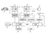
- FIG. 2 is a block diagram further embodying the functional block diagram of FIG. 1.
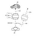
- FIG. 1 is a block diagram of this embodiment, and FIG. 2 is an operation explanatory diagram.
- an imaging apparatus such as a digital camera 10 does not include, for example, a shutter button, a finder, or a monitor screen, and includes an imaging unit 12, a detection unit 14, a determination unit 16, and a control unit 18.
- the imaging unit 12 performs imaging by subjecting the subject 22, which is an image formed by the imaging optical system, to photoelectric conversion and outputting an image signal.
- a detection unit 14, a determination unit 16, and a control unit 18 are provided.
- the photographer 20 automatically performs an automatic shutter based on the photographer's action without forcing troublesome operations such as an operation of framing to identify a subject and an operation of pressing the shutter after confirming the subject through the camera. Operation is possible.
- the automatic shutter may be either a mechanical shutter or an electronic shutter.
- the detection unit 14 functioning as a man-machine interface detects a direction of interest 20A in which the photographer 20 is visually interested.
- the direction of interest A can be a direction in which the face of the photographer 20 faces, for example.
- the direction of interest A may be the sight line direction or the gaze direction of the photographer 20.
- the optical axis 12A of the imaging optical system of the imaging unit 12 and the optical axis 14A of the detection optical system of the detection unit 14 are drawn on the same line. That is, the optical axis 12 ⁇ / b> A of the imaging unit 12 and the optical axis 14 ⁇ / b> A of the detection unit 14 match in plan view. However, the optical axis 12A of the imaging unit 12 and the optical axis 14A of the detection unit 14 may be parallel in plan view.
- the optical axis 12A of the imaging unit 12 and the optical axis 14A of the detection unit 14 may coincide with each other when viewed from the side (each optical axis is on the same line in the height direction), or parallel when viewed from the side. (Each optical axis is at a different height position). Eventually, the optical axis 12A of the imaging unit 12 and the optical axis 14A of the detection unit 14 are in agreement or in a parallel relationship.
- the direction of interest 20 ⁇ / b> A of the photographer 20 is in plan view from the direction of the optical axis 12 ⁇ / b> A in the imaging unit 12 of the imaging device 10. It is completely different. In such a case, the photographer 20 is regarded as having no intention to photograph. That is, the photographer 20 is looking at the subject 22 of interest, holding the imaging device 10 in his hand, and not holding the imaging device 10 on the line of sight of the photographer 20.
- the photographer 20 moves the imaging device 10 from the position indicated by the broken line in FIG. 2 to a solid line position that is in the middle of the direction of interest 20A of the photographer 20.
- the direction of interest 20A of the photographer 20 matches the direction of the optical axis 12A in the imaging unit 12 of the imaging device 10 in plan view.
- This operation is an operation of holding the imaging device 10 toward the subject 22, and can be said to be an operation directed to the photographing intention operation or the photographing posture of the photographer 20. In other words, it is a photo opportunity for the photographer to photograph instantaneously, intuitively or with his / her heart.
- the detection unit 14 functions as a man-machine interface, and captures the operation of the imaging device 10 being arranged at the solid line position in FIG.
- the determination unit 16 confirms that the direction of interest 20A of the photographer 20 detected by the detection unit 14 matches the direction (comparison information) of the allowable range centering on the optical axis 12A of the imaging optical system of the imaging unit 12. judge.
- the direction of interest 20 ⁇ / b> A of the photographer 20 is within the allowable range around the optical axis 12 ⁇ / b> A of the imaging optical system of the imaging unit 12.
- the direction of interest 20 ⁇ / b> A of the photographer 20 is the optical axis of the imaging optical system of the imaging unit 12. It means that the relation of 12A coincides or is parallel, and further, the relation of crossing at a small angle is included as an allowable range. That is, the determination unit 16 determines whether the photographer 20 holds the imaging device 10 toward the subject 22 based on the relationship between the direction of interest 20A and the optical axis 12A.
- the optical axis 12 ⁇ / b> A of the imaging optical system of the imaging unit 12 and the optical axis 14 ⁇ / b> A of the detection unit 14 match or have a parallel relationship. Therefore, even if the determination unit 16 determines that the direction of interest 20A of the photographer 20 detected by the detection unit 14 is an allowable range centering on the optical axis 14A of the detection optical system of the detection unit 14. Good. As a result, it can be said that the direction of interest 20 ⁇ / b> A is substantially equivalent to the determination that the direction of interest 20 ⁇ / b> A is an allowable range centering on the direction that coincides with the optical axis 12 ⁇ / b> A of the imaging optical system of the imaging unit 12. It is.
- the control unit 18 controls the imaging unit 12 at the imaging timing based on the output from the determination unit 16.
- the detection unit 14 that is a man-machine interface captures the operation of placing the imaging device 10 at the solid line position in FIG. 2, and the imaging unit 12 can automatically image the subject 22.
- the determination unit 16 determines that the detection unit 14 has detected the photographing intention motion of the photographer 20 or the operation toward the photographing posture, and the imaging unit via the control unit 18. 12 can automatically image. Therefore, without forcing the photographer 20 to perform troublesome operations such as framing and specifying the subject 22 and pressing the shutter after confirming the subject through the camera, the photographer 20 instantaneously and intuitively Or you can shoot with your heart.
- FIG. 3 is a block diagram further embodying the block diagram of FIG. 3, in addition to the control unit 100 having the functions of the imaging unit 12, the detection unit 14, the determination unit 16, and the control unit 18, the face distance detection unit 80, the posture detection unit 90, the user interface unit 110, An image storage unit 120, a power supply unit 130, and a notification unit 140 are provided.
- the imaging unit 12 that images the subject 22 includes the first imaging unit 30 and the first imaging control unit 40 shown in FIG.
- the first imaging unit 30 includes an imaging optical system 32 and an image sensor 34.
- the image sensor 34 photoelectrically converts an image formed by the imaging optical system 32 and outputs an image signal.
- the first image pickup unit 30 can be optically zoomed, and can be triple zoomed by adjusting the focal length from 28 mm to 84 mm, for example, under the control of the first image pickup control unit 40.
- the first imaging control unit 40 can adjust the angle of view (focal length adjustment) of the first imaging unit 30 based on the distance between the imaging device 10 and the photographer 20. Details of the angle of view adjustment will be described later.
- the first imaging control unit 40 can perform autofocus (AF) control of the first imaging unit 30.
- AF autofocus
- a contrast AF method is employed as the AF method of the first imaging unit 30, and a continuous AF is applied to an object closest to the imaging device 10 with respect to a point on the optical axis 12A.
- an arbitrary point may be used as an AF point by the photographer.
- the first imaging unit 30 performs AF operation continuously during the shooting mode. When the optical axis coincidence is determined by the determination unit 16 as described above, the point at the coincidence is set as an AF point. Imaging is performed.
- the second imaging control unit 60 performs the above-described AF operation and angle of view adjustment (focal length adjustment) on the basis of the control signal from the control unit 100, and applies to the image from the first imaging unit 30. Perform image processing. In addition, the second imaging control unit 60 transfers the focus distance information obtained as a result of the AF operation to the control unit 100, and is used when the optical axis coincidence detection is performed by the determination unit 16 described above.
- the detection unit 14 that detects the direction of interest 20A of the photographer 20 includes a second imaging unit 50, a second imaging control unit 60, and a face direction detection unit 70 illustrated in FIG.
- the second imaging unit 50 includes a detection optical system 52 and an image sensor 54.
- the image sensor 54 photoelectrically converts the image formed by the detection optical system 52 and outputs an image signal.
- the second imaging control unit 60 controls the imaging operation of the second imaging unit 50.
- the second imaging unit 50 has a wide-angle detection optical system 52, and can perform imaging with pan focus.
- the imaging condition of the second imaging unit 50 is set by inputting setting information from the user interface unit 110 via the control unit 100 and the second imaging control unit 60.
- the image from the second imaging unit 50 is subjected to image processing by the second imaging control unit 60 and transmitted to the face direction detection unit 70 and the face distance detection unit 80.
- the face direction detection unit 70 has a function of detecting the face of the photographer 20 and detecting the direction of the face in order to detect the interest direction 20A of the photographer 20. That is, in the present embodiment, the direction in which the photographer 20 faces is positioned as the interest direction 20A in which the photographer 20 is visually interested. Details of this face detection and face direction detection will be described later.
- the face distance detection unit 80 detects the distance between the imaging device 10 and the photographer 20 face.
- the distance detection by the face distance detection unit 80 is performed by extracting a plurality of feature points of the face detected in the same manner as the face direction detection unit 70, and based on the distance between the feature points, the imaging device 10 and the photographer 20 The distance between the face and the face is detected relatively.
- Information about the facial feature points used in the face distance detection unit 80 may be supplied from the face direction detection unit 70.
- the face distance detection unit 80 detects based on the image information from the second imaging unit 50.
- the detection is not limited to such image determination, and for example, infrared rays or the like You may use distance measuring means, such as measuring distance physically with light.
- the posture detection unit 90 detects the posture of the imaging device 10.
- the posture detection unit 90 uses the optical axis of the imaging optical system 32 of the first imaging unit 30 as a reference axis (Z axis), and two orthogonal axes on a plane orthogonal to the Z axis as an X axis and a Y axis. Rotation postures for each of the Y and Z axes are detected.
- the posture information detected by the posture detection unit 90 is sent to the control unit 100 and used as information when extracting the facial feature points of the photographer 20 detected by the face direction detection unit 70. Further, the control unit 100 can adjust the frame direction so that the vertical direction of the frame frame imaged by the first imaging unit 30 is parallel to the gravity direction detected by the posture detection unit 90. .
- the control unit 100 includes a determination unit 101 having the function of the determination unit 16 and a shutter control unit 102 having the function of the control unit 18 in addition to controlling the imaging apparatus 10.
- Information operated by the photographer 20 is input to the user interface 110, and information on the imaging device 10 side is displayed as necessary.
- the user interface 110 is not provided with a shutter button.
- the image storage unit 120 functions as a working memory for the control unit 100 in addition to recording an image captured by the first imaging unit 30.
- the notification unit 140 notifies the photographer 20 of the degree of coincidence between the direction of interest 20A of the photographer 20 and the direction of the allowable range centering on the optical axis 12A of the image pickup optical system of the image pickup unit 12 by, for example, an electronic sound. To do.
- the direction of interest 20A where the photographer 20 is visually interested is the direction in which the face of the photographer 20 is facing. It is said.
- “Face direction estimation based on face feature point tracking with robustness and precision” introduced in [0106] of Patent Document 1
- the method of “Journal 2001/8 Vol. J8 4-D-II No.8 pp.1762-1771)” can be used. This technique is also described in [0106] to [0119] of Patent Document 1.
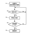
- FIG. 4 is an operation flowchart of the detection unit 14 and the determination unit 16 using the above method.
- step 1 initialization is performed.
- the user interface unit 110 in FIG. 3 can include a mode switching operation unit (mode switching unit in a broad sense) for switching between a shooting mode and an initial setting mode.
- mode switching operation unit mode switching unit in a broad sense
- the initial setting in step 1 can be performed in an initial setting mode different from the shooting modes after step 2.
- a plurality of feature points are registered from the face images stored in the storage unit in the control unit 100 or the image storage unit 120.
- the face direction detection unit 70 extracts two eyes and a nose or two eyes and a mouth.
- a method for detecting the facial feature point a known method described in the above-mentioned document or the like can be adopted, and the description thereof is omitted.
- Patent Document 1 calculates the angle and direction in which the face is rotated with respect to the horizontal axis in addition to the angle and direction in which the face is rotated with respect to the vertical axis. Although the method of patent document 1 can be used as detection of the direction of interest 20A of this embodiment, a simpler method is demonstrated here.
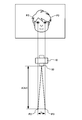
- FIG. 5 shows the mouth position P1 and the left and right eye positions P2 and P3 as a plurality of facial feature points registered as the initial settings in step 1 of FIG.
- FIG. 5 is an image when the photographer 20 faces the second imaging unit 50 of the imaging device 10. Therefore, in the image of FIG. 5, the direction of interest 20 ⁇ / b> A of the photographer 20 matches or is in parallel with the optical axis 12 ⁇ / b> A of the imaging optical system 32 of the first imaging unit 30.
- the image of the photographer 20 is acquired by the second imaging unit 50 (detection unit 14) (step 2), and the face direction detection unit 70 similarly selects a plurality of feature points for the acquired image.
- the feature point is extracted (step 3), and the determination unit 101 compares it with the registration information (comparison information) in the initial setting (step 4), and the imaging operation controlled by the shutter control unit 102 is the first based on the comparison result. This is performed by the imaging unit 30 (step 5).
- the determination unit 101 can determine whether it is coincident with 12A or in a parallel relationship.
- the direction of interest 20A detected by the face direction detection unit 70 is centered on the optical axis 12A of the imaging optical system 32 of the first imaging unit 30. It is determined that the direction matches the allowable range. Therefore, even if the three points P1, P2, and P3 in FIG. 5 do not completely match, the determination unit 101 in the control unit 100 determines that it is the photographing timing if they match within a preset allowable range. You may do it.
- the centroids of inverted triangles may be compared. Since the shape of the inverted triangle is different between the time of facing (FIG. 5) and the time of non-facing (FIG. 6), the center of gravity of the inverted triangle is also different between the time of facing and the time of non-facing. Therefore, as another comparison method in Step 4 of FIG. 4, the center of gravity of the inverted triangle and the allowable range thereof at the time of direct facing (FIG. 5) are registered, and the inverted triangle in the image acquired in the shooting mode is registered. It may be compared with the center of gravity position.
- the height and length of the inverted triangle may be compared.
- the area S of the inverted triangle at the time of facing (FIG. 5) is the maximum
- the height H and the length L of the inverted triangle are also the maximum.
- the face is deviated from the time of facing, the inverted triangle is distorted as shown in FIG. 6, so that at least one of the height H and the length L of the inverted triangle is shorter than that of the facing time.
- L ′ ⁇ L and the height H does not change.
- the height H 'of the inverted triangle at that time becomes shorter than the height H at the time of facing. If the face rotates with respect to both the vertical axis and the horizontal axis, both the height H 'and the length L' of the inverted triangle at that time are shorter than those at the front. Therefore, as a comparison method in Step 4 of FIG. 4, the height H and the length L of the inverted triangle at the time of facing in the initial setting mode are calculated, and the shorter height H1 and length L1 are registered. In addition, the height H2 and the length L2 of the inverted triangle extracted from the image acquired in the shooting mode may be compared. If H1 ⁇ H2 and L ⁇ L2, the determination in step 4 in FIG. 4 is YES, and if H2 ⁇ H1 or L2 ⁇ L1, the determination in step 4 in FIG. 4 is NO.
- the second imaging unit is used by using the tilt information of the imaging device 10 detected by the posture detection unit 90 of FIG.
- the frame of the image acquired at 50 can be corrected. In this way, even when the imaging device 10 is tilted at the time of image acquisition, it can be corrected to a state in which an image is always acquired in a fixed posture.
- the initial setting (step 1) in FIG. 4 is not limited to being performed every time the power is turned on, and may be performed by switching to the initial setting mode by the photographer 20 operation. At this time, when the photographer 20 shares one imaging device 10, it is possible to make initial settings for a plurality of photographers 20. When the power is turned on, for example, a preset priority photographer may be used, and the registered photographer 20 may be selected.
- one or a plurality of threshold values can be set in the mismatch range for the area, center of gravity, height, and length of the inverted triangle described above. .
- the direction of interest 20A detected by the detection unit 14 is an allowable range centered on the optical axis 12A of the imaging optical system 32 of the first imaging unit 30.
- the shutter operation is automatically performed at the timing coincident with the direction of the image, and the image of the subject 22 is captured by the image sensor 34 of FIG. For this reason, it is not necessary for the photographer 20 to operate the shutter button, but it is convenient in use if the photographer 20 can be notified of the photographing timing and whether the photographing timing is near or far.
- coincidence detection can be performed by comparing the area of the inverted triangle, comparing the center of gravity of the inverted triangle, comparing the height of the inverted triangle, and the like, but it is also possible to detect other degrees in the comparison process. In order to detect any other degree, it is only necessary to set a plurality of threshold levels as comparison information.
- the notification unit 140 of FIG. 3 changes the electronic sound, for example, according to the degree of coincidence / inconsistency or the like under the control of the control unit 100.
- the notifying unit 140 intermittently outputs an electronic sound with a long interval such as “beep ... ......”, and shortens the interval as the degree of disagreement becomes smaller. For example, a continuous sound is used.
- the notification unit 140 can output a shutter sound when the imaging operation is performed. As a result, the photographer 20 can feel the photographing timing and the fact that the photographing has been performed.
- the method of notifying the photographer 20 is not limited to changing the interval of electronic sounds, in addition to notifying by changes in sound such as volume, pitch, timbre, tone, etc., and various outputs such as display by lighting or flashing It can be selected from the forms.
- the angle of view is uniquely determined by the focal length.
- the angle of view and the focal length are adjusted based on the distance (face distance) from the imaging device 10 to the face of the photographer 20.
- the face distance detection unit 80 shown in FIG. 3 detects the distance (face distance) from the imaging device 10 to the face of the photographer 20 based on the image of the photographer 20 acquired by the second imaging unit 50.
- Yes. 7 and 8 show the principle of distance detection based on a plurality of images shot under the same shooting conditions.
- the face of the photographer 20 is imaged in a state of being close to the second imaging unit 50 at a distance A1
- the face occupied in the frame is large, and for example, the position P2 of the second eye in the face , P3 has a longer distance L.
- FIG. 7 shows the principle of distance detection based on a plurality of images shot under the same shooting conditions.
- the face distance detection unit 80 is not limited to using the image of the photographer 20, and may measure the distance using infrared rays or the like.
- the face distance A detected by the face distance detection unit 80 is input to the first imaging control unit 40 via the control unit 100, and the angle of view ⁇ of the first imaging unit 30 based on the face distance A. (Focal distance f: not shown) is adjusted by the first imaging control unit 40. As shown in FIG. 9, when the face distance A1 is short, the angle of view ⁇ 1 is increased and the focal length f1 (not shown) is increased. On the other hand, as shown in FIG. 10, when the face distance A2 is long, the angle of view ⁇ 2 is narrowed and the focal length f2 (not shown) is shortened.
- the focal length f can be adjusted to 28 mm to 84 mm, for example, when the distance A between the imaging device 10 and the photographer 20 is 200 mm or less, the focal length f is 28 mm (the angle of view is a wide angle).
- the focal length f is 84 mm (the angle of view is narrow), and when the distance A is between 200 mm and 500 mm, the focal length f changes linearly. (The angle of view also changes linearly.)
- the longer the distance A detected by the face distance detection unit 80 the longer the angle of view of the first imaging unit 30 is. Adjustment is made to narrow ⁇ . If the angle of view ⁇ is narrow in this manner, the subject 22 ahead of the direction of interest 20A of the photographer 20 is framed when the optical axis 12A of the imaging optical system 32 of the first imaging unit 30 is slightly displaced from the subject 22. It becomes difficult to grasp as an image inside. On the other hand, as the distance A detected by the face distance detection unit 80 is shorter, the angle of view ⁇ of the first imaging unit 30 is adjusted to be wider.
- the subject 22 ahead of the direction of interest 20A of the photographer 20 can be moved within the frame even if the optical axis 12A of the imaging optical system 32 of the first imaging unit 30 is slightly shifted from the subject 22. It is easy to catch as an image.
- comparison information for the determination unit 101 to determine match / mismatch a plurality of types of comparison information so that the allowable width varies depending on the distance from the photographer 20 to the imaging device 10. Is set.
- FIG. 11 is a block diagram of a control system that changes the allowable range of coincidence according to the angle of view (focal length) adjustment.
- the control circuit 100 is provided with a comparison information storage unit 103.
- the comparison information storage unit 103 stores a plurality of types of comparison information 103A, 103B, 103C,.
- the determination unit 101 selects one of the plurality of types of comparison information 103A, 103B, 103C,.
- the determination unit 101 compares the direction of interest 20A from the face direction detection unit 70 with the selected comparison information.
- the plurality of types of comparison information 103A, 103B, 103C,... are the above-described comparisons that are generated based on a plurality of feature points in the image when the photographer 20 faces the second imaging unit 50. Although the information is common, each is different in that the allowable width is different.
- a plurality of types of comparison information 103A, 103B, 103C,... are stored in association with face distances. In this embodiment, the plurality of types of comparison information 103A, 103B, 103C,... are set such that the longer the face distance, the narrower the allowable width, and the shorter the distance, the wider the allowable width.
- the angle of view ⁇ 1 is set to a wide angle.
- the coincidence determination in the direction 12A can be made.
- the angle of view ⁇ 2 is set to a narrow angle. The coincidence determination in the direction 12A can be made.
- FIG. 12 is a flowchart showing the overall operation in the automatic shooting mode according to the present embodiment. It is assumed that the initial setting in step 1 in FIG. 4 has been completed before the operation in FIG.
- the imaging apparatus 10 is turned on (step 1) and set to a shooting mode (step 2). If the manual shooting mode or the automatic shooting mode can be selected as the shooting mode of step 2, the automatic shooting mode is set.
- step 3 it is determined whether or not the photographer 20 is photographed by the second imaging unit 50 and the face is detected based on a plurality of feature points in the photographer 20 face image (step). 3). If the determination in step 3 is NO, the process waits until a face is detected.
- the face direction detection unit 70 detects the face direction as the interest direction 20A of the photographer 20 (step 4).
- this face direction detection is the area S of the inverted triangle formed by the three feature points P1 to P3, the center of gravity of the inverted triangle, or the height H and length L of the inverted triangle. It is to seek.
- the face distance detection unit 80 detects the face distance A from the imaging device 10 to the face based on, for example, two feature points P2 and P3 (step 5). ). Information on the face distance A is transmitted to the control unit 100.
- the control unit 100 adjusts the angle of view based on the face distance A (step 6). That is, the control unit 100 sets the angle of view ⁇ 1 to a wide angle (focal length f1 is shortened) when the distance A1 is short as shown in FIG. 9, and sets the angle of view ⁇ 2 to a narrow angle (focus point when the distance A2 is long as shown in FIG.
- the first imaging control unit 40 is controlled so that the distance f2 is increased.
- the posture detection unit 90 detects the posture of the imaging device 10 using, for example, sensors in three orthogonal axes (step 7).
- the posture information of the imaging device 10 is transmitted to the control unit 100, and can be used for image processing or the like at the time of coincidence detection performed in step 9 performed later if necessary.
- an autofocus (AF) operation is performed (step 8), and information on the in-focus distance at this time is transmitted to the control unit 100. Even if the focal length is changed in step 8, the angle of view is not changed.
- step 9 the determination unit 101 performs a match determination (step 9). This coincidence determination is performed by comparing the face direction acquired in step 5 with the initially set comparison information. At this time, when a plurality of types of comparison information are registered as shown in FIG. 11, one comparison information corresponding to the face distance A acquired in step 5 is selected. If the determination in step 9 is YES, the shutter control unit 102 controls the first imaging control unit 40, and the subject 22 is automatically captured by the first imaging unit 30 (step 10). If the determination in step 9 is NO, the process returns to step 3 and steps 3 to 9 are repeated.
- the operations indispensable for the automatic photographing based on the coincidence detection between the detected face direction and the comparison information are steps 3, 4 and 9, and the other steps can be performed as necessary.
- the execution order of the optional step 5-8 can be arbitrarily changed as long as there is no restriction on the execution of the control, or may be executed in parallel.
- the direction of interest 20A detected by the detection unit 14 is used, and in this embodiment, the face direction of the photographer 20 is detected.
- the present invention is not limited to this.
- As the direction of interest 20A attention may be paid to the photographer 20 and the gaze direction or the line-of-sight direction of the photographer 20 may be detected.
- Various methods can be adopted for detecting the gaze direction or the line-of-sight direction of the photographer 20, and for example, as described in FIG. 13 of Patent Document 1, by image processing based on the pupil position in the eye of the photographer 20 Can be sought.
- the present invention can also be applied to an imaging apparatus in which shutters, viewfinders, or monitor screens are scattered.
- a mode switching unit is provided in the user interface unit 110 in FIG. 3 so that the photographing mode can be switched between the automatic photographing mode and the manual mode.
- the manual shooting mode as in the past, an image framed on the viewfinder or the monitor screen is picked up by a shutter operation, while the shooting operation according to the present invention can be performed in the automatic shooting mode.
- the plurality of pieces of comparison information 103A, 103B, 103C,... are not different in the allowable width based on the face distance of the same photographer 20, but are registered for each of the plurality of photographers 20. It may be.
Landscapes
- Engineering & Computer Science (AREA)
- Multimedia (AREA)
- Signal Processing (AREA)
- Physics & Mathematics (AREA)
- General Physics & Mathematics (AREA)
- Studio Devices (AREA)
- Details Of Cameras Including Film Mechanisms (AREA)
- Cameras In General (AREA)
Abstract
広い空間の中から撮影者が関心のある被写体を瞬間的にまたは直感的に撮影することができる撮像装置を提供する。 撮像装置10は、撮像光学系32により結像した像を光電変換して画像信号を出力することで撮像する撮像部12と、撮影者20が視覚的に関心を持つ関心方向20Aを検出する検出部14と、撮像光学系32の光軸12Aを中心とする許容範囲の方向を比較情報とし、検出部14にて検出された関心方向20Aが比較情報と一致したことを判定する判定部16と、判定部16からの出力に基づく撮影タイミングで、撮像部12を撮像制御する制御部18とを有する。
Description
本発明は、デジタルカメラ等の撮像装置に関する。
従来、カメラ撮影に際しては、被写体を確認した後にシャッターを操作するのが一般的である。ビューファインダー付カメラであればファインダーにて、デジタルカメラであればモニター画面にて、それぞれ被写体を確認してフレーミングを行い、その後にシャッターを操作している。
一方、撮影者の負担を軽減するための提案もなされている。特許文献1に記載の発明は、被写体を撮影する第1のカメラに加えて、撮影者を撮影する第2のカメラを設けている。第2のカメラの撮影画像により撮影者が興味を示す方向を追尾し、それに基づいて撮影したい被写体が存在すると予想される位置に第1のカメラをパン・チルト機構で移動させて、撮影支援している。
ビューファインダーやモニター画面が存在すると、それらを用いてフレーミングするという操作を経て撮影することを強いることになる。また、カメラに備えられたファインダーやモニター画面に映る範囲以外にも興味を引く被写体が存在するにもかかわらず、一旦カメラを構えると、被写体の対象がファインダーやモニター画面の範囲内に制限されてしまっていた。
一方、例えばカメラが極限まで小型化される等の理由で、ビューファインダーやモニター画面がなくなる可能性もある。
特許文献1では撮影者の負担を軽減しいているが、これを実現するには撮影者が興味を示す方向(縦軸方向と横軸方向の双方)と角度の算出が不可欠である(段落0110~0119参照)。よって、大規模なシステムとならざるを得ない。
本発明の幾つかの態様によれば、撮影者に、フレーミングして被写体を特定させる操作や、カメラを通じて被写体を確認した後にシャッター押下する操作等の煩わしい作業を強いずに、しかも広い空間の中から撮影者が関心のある被写体を瞬間的にまたは直感的に撮影することができる撮像装置を提供することができる。
本発明の一態様は、
撮像光学系により結像した像を光電変換して画像信号を出力することで撮像する撮像部と、
撮影者が視覚的に関心を持つ関心方向を検出する検出部と、
前記撮像光学系の光軸を中心とする許容範囲の方向を比較情報とし、前記検出部にて検出された関心方向が前記比較情報と一致したことを判定する判定部と、
前記判定部からの出力に基づく撮影タイミングで、前記撮像部を撮像制御する制御部と、
を有する撮像装置に関わる。
撮像光学系により結像した像を光電変換して画像信号を出力することで撮像する撮像部と、
撮影者が視覚的に関心を持つ関心方向を検出する検出部と、
前記撮像光学系の光軸を中心とする許容範囲の方向を比較情報とし、前記検出部にて検出された関心方向が前記比較情報と一致したことを判定する判定部と、
前記判定部からの出力に基づく撮影タイミングで、前記撮像部を撮像制御する制御部と、
を有する撮像装置に関わる。
本発明の一態様によれば、撮影者が視覚的に関心を持つ関心方向が撮像装置の向けられた方向(撮像光学系の光軸を中心とする許容範囲の方向)と一致した時に、自動的に撮像動作を行うことができる。このため、被写体の対象がファインダーやモニター画面の範囲内に制限されずに、広い空間の中から撮影者が関心のある被写体を瞬間的にまたは直感的に撮影することができる。
本発明の一態様では、前記検出部は検出光学系を含み、前記検出部の検出光学系の光軸と前記撮像光学系の光軸とは、一致または平行な関係にあり、前記判定部は、前記検出部にて検出された関心方向が、前記撮像光学系の光軸を中心とする許容範囲の方向と一致したことを判定することに代えて、前記検出光学系の光軸を中心とする許容範囲の方向と一致したことを判定することができる。
こうすると、被写体に向けられる撮像部の光軸を直接検出することなく、撮影者に向けて配置できる検出部の光軸に基づいて許容範囲を設定することができる。
本発明の一態様では、前記撮像部は、前記撮像光学系を含む第1のカメラを有し、前記検出部は、前記検出光学系を介して前記撮影者の顔の画像を撮像する第2のカメラと、前記第2のカメラから取得される前記画像中の複数の特徴点に基づいて、前記関心方向を検出する検出部とを有することができる。
このように、被写体を撮像する第1のカメラを撮像部とした場合、検出部として、撮影者を撮像する第2のカメラを追加することで、撮影者の関心方向の検出と、一致判定とを行うことができる。ここで、第2のカメラで撮像された画像、特に顔画像中には、顔の向き、視線方向、注視方向等を特定できる複数の特徴点が存在する。よって、撮影者が視覚的に関心を示す関心方向は、画像、特に顔画像中の複数の特徴点から、顔の向き、視線方向または注視方向として検出することができる。
本発明の一態様では、前記比較情報は、前記撮影者が前記第2のカメラと正対した状態で前記第2のカメラで撮像された画像中の複数の特徴点に基づいて生成することができる。撮影者が前記第2のカメラと正対した状態とは、撮影者の関心方向が第1カメラの撮像光学系の光軸と一致し、または平行である状態となり、許容範囲の中心となる方向である。第2のカメラで撮像された正対画像、特に顔画像中の顔の向き、視線方向、注視方向等を特定できる複数の特徴点は、許容範囲の中心を示し、それに基づいて中心からの許容幅を含む許容範囲を含む比較情報を設定できる。
本発明の一態様では、少なくとも撮影モードと初期設定モードとに切り換えるモード切換部をさらに有し、前記比較情報は、前記初期設定モードで設定することができる。
比較情報は電源ON時等に毎回収集してもよいが、初期設定モードで一旦登録しておくだけでも良く、こうすると電源ON時に撮影モードに速やかに移行できるからである。
本発明の一態様では、前記モード切換部は、前記撮影モードとして自動撮影モードと手動モードとに切り換え可能であり、前記制御部は、前記自動撮影モードの時に、前記判定部からの出力に基づく撮影タイミングで前記撮像部を撮像制御することができる。
こうすると、従来通り手動によりシャッター操作するものと本発明の自動シャッター機能とを使い分けることができる。従って本発明の一態様では、シャッター釦、ファインダーまたは表示モニターが存在する撮像装置にも適用でき、自動撮影モードではそれらの装備を使用せずに撮影できる。
本発明の一態様では、前記撮影者から前記撮像装置までの距離を検出する距離検出部をさらに有し、前記制御部は、前記距離検出部にて検出された距離に基づいて、前記撮像部の画角を調整することができる。
撮影者から撮像装置までの距離の情報を、撮影者が広角撮影したいのか、あるいはズームアップ撮影したいのかの意思の表れと捉え、その距離に基づいて画角を自動調整することができる。
本発明の一態様では、前記比較情報は、前記撮影者から前記撮像装置までの距離に応じて許容幅が異なるように複数種が設定され、前記判定部は、前記距離検出部からの距離に基づいて、前記複数種の比較情報の中の一つを前記比較情報として選択することができる。
こうすると、許容幅の異なる複数種の比較情報を、撮影者から前記撮像装置までの距離に応じて使い分けることができる。撮影者から前記撮像装置までの距離に応じて画角を調整する場合には、画角によって一致検出の精度が高く求められる場合とそうでない場合があるからである。
この場合、前記制御部は、前記距離検出部にて検出された距離が長いほど前記撮像部の前記画角を狭くするように調整し、前記距離が短いほど前記撮像部の前記画角を広くなるように調整し、前記複数種の比較情報は、前記距離が長いほど許容幅を狭く、前記距離が短いほど許容幅を広く設定することができる。
画角が広角であれば、撮像部の光軸が被写体位置との関係で多少ずれても、関心のある被写体は広角画像中に位置させることができるからである。逆に、画角が狭角であると、撮像部の光軸が被写体位置との関係で多少でもずれると、関心のある被写体は狭角画像中に位置させることができないからである。
本発明の一態様では、前記判定部が一致判定した時に、前記撮影者に撮影が実施されることを告知する告知部をさらに有することができる。これにより、撮影者はシャッター釦を操作しなくても、撮影されたことを実感することができる。
この場合、前記判定部では、前記関心方向と前記比較情報との不一致の度合いが検出され、前記告知部は、前記判定部で判定された不一致の度合いに応じて出力を異ならせることができる。こうすると、撮影者は、撮影タイミングが近いか遠いかも実感することができる。
以下、本発明の好適な実施の形態について詳細に説明する。なお以下に説明する本実施形態は特許請求の範囲に記載された本発明の内容を不当に限定するものではなく、本実施形態で説明される構成の全てが本発明の解決手段として必須であるとは限らない。
1.実施形態の概要
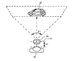
図1は本実施形態のブロック図であり、図2は動作説明図である。図1において、撮像装置例えばデジタルカメラ10は、例えばシャッター釦や、ファインダーまたはモニター画面は有せず、撮像部12、検出部14、判定部16及び制御部18を有する。撮像部12は、撮像光学系により結像した像である被写体22を光電変換して画像信号を出力することで撮像する。撮像部12に撮像動作させるために、検出部14、判定部16及び制御部18が設けられている。特に本実施形態では、撮影者20が、フレーミングして被写体を特定させる操作や、カメラを通じて被写体を確認した後にシャッター押下する操作等の煩わしい作業を強いずに、撮影者の行動に基づいて自動シャッター動作を可能としている。自動シャッターは、メカニカルシッャターまたは電子シャッターのいずれでも良い。
図1は本実施形態のブロック図であり、図2は動作説明図である。図1において、撮像装置例えばデジタルカメラ10は、例えばシャッター釦や、ファインダーまたはモニター画面は有せず、撮像部12、検出部14、判定部16及び制御部18を有する。撮像部12は、撮像光学系により結像した像である被写体22を光電変換して画像信号を出力することで撮像する。撮像部12に撮像動作させるために、検出部14、判定部16及び制御部18が設けられている。特に本実施形態では、撮影者20が、フレーミングして被写体を特定させる操作や、カメラを通じて被写体を確認した後にシャッター押下する操作等の煩わしい作業を強いずに、撮影者の行動に基づいて自動シャッター動作を可能としている。自動シャッターは、メカニカルシッャターまたは電子シャッターのいずれでも良い。
マンマシンインターフェースとして機能する検出部14は、撮影者20が視覚的に関心を示す関心方向20Aを検出する。図2に示すように、関心方向Aとは、例えば撮影者20の顔が正対する方向とすることができる。関心方向Aとは、撮影者20の視線方向または注視方向としてもよい。
ここで、本実施形態では、撮影者20と撮像装置10とを平面視で示す図2において、撮像部12の撮像光学系の光軸12Aと、検出部14の検出光学系の光軸14Aとは同一線上に描かれている。つまり、撮像部12の光軸12Aと、検出部14の光軸14Aとは、平面視では一致している。これに限らず、撮像部12の光軸12Aと、検出部14の光軸14Aとは、平面視で平行であっても良い。また、撮像部12の光軸12Aと、検出部14の光軸14Aとは、側面視で一致(各光軸が高さ方向で同一線上にある)していても良いし、側面視で平行(各光軸が異なる高さ位置にある)であってもよい。結局、撮像部12の光軸12Aと、検出部14の光軸14Aとは、一致するか、または平行の関係にある。
図2の撮影者20にとって、破線で示す位置に撮像装置10が配置されている時には、撮影者20の関心方向20Aは、撮像装置10の撮像部12における光軸12Aの方向とは平面視で全く異なっている。このような場合、撮影者20には撮影意思はないとみなされる。つまり、撮影者20は関心対象である被写体22を眺めており、撮像装置10を手に持ったままで、撮影者20の視線の線上に撮像装置10を構えていない状態である。
その後、撮影者20が、撮像装置10を図2にて破線で示す位置から、撮影者20の関心方向20Aの途中位置である実線位置に移動させる。撮影者20の関心方向20Aは、撮像装置10の撮像部12における光軸12Aの方向と平面視で一致する。この動作は、被写体22に向けて撮像装置10を構えた動作であり、撮影者20の撮影意思動作または撮影姿勢に向けた動作であると言える。換言すれば、撮影者が瞬間的に、直感的に、あるいは心のままに撮影するシャッターチャンスである。本実施形態では、検出部14がマンマシンインターフェースとして機能し、図2の実線位置に撮像装置10が配置される動作を捉えて、自動的に被写体22を撮像している。
判定部16は、検出部14にて検出された撮影者20の関心方向20Aが、撮像部12の撮像光学系の光軸12Aを中心とする許容範囲の方向(比較情報)と一致したことを判定する。撮影者20の関心方向20Aが、撮像部12の撮像光学系の光軸12Aを中心とする許容範囲の方向とは、撮影者20の関心方向20Aが、撮像部12の撮像光学系の光軸12Aと一致し、または平行の関係であることはもちろん、さらには少ない角度で交差する関係も許容範囲として含むことを意味する。つまり、判定部16は、関心方向20Aと光軸12Aとの関係から、撮影者20が被写体22に向けて撮像装置10を構えたか否かを判定するのである。
ここで、上述の通り、撮像部12の撮像光学系の光軸12Aと、検出部14の光軸14Aとは、一致するか、または平行の関係にある。よって判定部16は、検出部14にて検出された撮影者20の関心方向20Aが、検出部14の検出光学系の光軸14Aを中心とする許容範囲の方向であることを判定してもよい。このことは、結果的に、関心方向20Aが、撮像部12の撮像光学系の光軸12Aと一致する方向を中心とする許容範囲の方向であると判定したことと実質的に等価と言えるからである。
制御部18は、判定部16からの出力に基づく撮影タイミングで、撮像部12を撮像制御する。こうして、マンマシンインターフェースである検出部14が、図2の実線位置に撮像装置10が配置される動作を捉えて、撮像部12が自動的に被写体22を撮像することができる。
以上の通り、本実施形態によれば、撮影者20の撮影意思動作または撮影姿勢に向けた動作を検出部14が検出したことを判定部16が判定して、制御部18を介して撮像部12が自動撮像することができる。よって、撮影者20に、フレーミングして被写体22を特定させる操作や、カメラを通じて被写体を確認した後にシャッター押下する操作等の煩わしい作業を強いずに、撮影者20が瞬間的に、直感的に、または心のままに撮影することができる。
2.具体的な実施形態
2.1.装置の全体説明
次に、本発明をより具体化した実施形態について、図3を参照して説明する。図3は、図1のブロック図をさらに具体化したブロック図である。図3には、撮像部12と、検出部14と、判定部16及び制御部18の機能を備えた制御部100に加えて、顔距離検出部80、姿勢検出部90、ユーザーインターフェース部110、画像記憶部120、電源部130及び告知部140が設けられている。
2.1.装置の全体説明
次に、本発明をより具体化した実施形態について、図3を参照して説明する。図3は、図1のブロック図をさらに具体化したブロック図である。図3には、撮像部12と、検出部14と、判定部16及び制御部18の機能を備えた制御部100に加えて、顔距離検出部80、姿勢検出部90、ユーザーインターフェース部110、画像記憶部120、電源部130及び告知部140が設けられている。
被写体22を撮像する撮像部12は、図3に示す第1の撮像部30と第1の撮像制御部40とで構成されている。第1の撮像部30は、撮像光学系32とイメージセンサ34とを有する。イメージセンサ34は、撮像光学系32により結像した像を光電変換して画像信号を出力する。
この第1の撮像部30は、光学ズーム可能であり、第1の撮像制御部40の制御により、焦点距離を例えば28mmから84mmに調整して3倍ズームが可能である。この第1の撮像制御部40は、撮像装置10と撮影者20との距離に基づいて第1の撮像部30の画角調整(焦点距離調整)を行うことができる。画角調整の詳細については後述する。
第1の撮像制御部40は、第1の撮像部30のオートフォーカス(AF)制御を行なうことができる。第1の撮像部30のAF方式として例えばコントラストAF方式が採用され、光軸12A上のポイントに対して撮像装置10に最も近い物体にコンティニュアスAFをかける。これに代えて、撮影者によって任意のポイントをAFポイントとしても良い。なお、第1の撮像部30は、撮影モード中は連続的にAF動作を行い、上述の通り判定部16によって光軸一致の判定がなされた場合には、その一致時のポイントをAFポイントとして撮像が行なわれる。
第2の撮像制御部60は、制御部100からの制御信号に基づいて、上述したAF動作や画角調整(焦点距離調整)を実施するほか、第1の撮像部30からの画像に対して画像処理を実施する。また、第2の撮像制御部60は、AF動作の結果得られた合焦距離情報を制御部100に転送され、上述した判定部16による光軸一致検出時に利用に供される。
撮影者20の関心方向20Aを検出する検出部14は、図3に示す第2の撮像部50、第2の撮像制御部60及び顔方向検出部70を有する。第2の撮像部50は、検出光学系52とイメージセンサ54とを有する。イメージセンサ54は、検出光学系52により結像した像を光電変換して画像信号を出力する。第2の撮像制御部60は、第2の撮像部50の撮像動作を制御する。
第2の撮像部50は、広角形の検出光学系52を有し、パンフォーカスで撮像ができるようになっている。第2の撮像部50の撮像条件は、ユーザーインターフェース部110からの設定情報を制御部100及び第2の撮像制御部60を介して入力設定される。
第2の撮像部50からの画像は、第2の撮像制御部60にて画像処理されて、顔方向検出部70と顔距離検出部80とに送信される。
顔方向検出部70は、撮影者20の関心方向20Aを検出するために、撮影者20の顔を検出した上で、その顔の向きを検出する機能を有する。つまり、本実施形態では、撮影者20の顔が向いている方向を、撮影者20が視覚的に関心を示す関心方向20Aと位置づけている。この顔検出と顔方向検出の詳細については後述する。
顔距離検出部80は、撮像装置10と撮影者20の顔との間の距離を検出する。顔距離検出部80での距離検出は、顔方向検出部70と同様にして検出される顔の複数の特徴点を抽出し、その特徴点間の距離に基づいて、撮像装置10と撮影者20の顔との間の距離を相対的に検出する。なお、顔距離検出部80にて用いられる顔の特徴点についての情報は、顔方向検出部70から供給を受けても良い。
なお、本実施形態では、顔距離検出部80は、第2の撮像部50からの画像情報に基づいて検出しているが、このような画像判定から検出するものに限らず、例えば赤外線等の光等によって物理的に距離測定する等の距離測定手段を用いても良い。
姿勢検出部90は、撮像装置10の姿勢検出を行う。姿勢検出部90は、第1の撮像部30の撮像光学系32の光軸を基準軸(Z軸)とし、Z軸と直交する平面上の直交二軸をX軸及びY軸とし、X,Y,Z軸の各々に対する回転姿勢を検出する。姿勢検出部90にて検出された姿勢情報は、制御部100に送出され、顔方向検出部70にて検出された撮影者20の顔の特徴点抽出時の情報として利用される。また、制御部100では、第1の撮像部30で撮像されるフレーム枠の縦方向が、姿勢検出部90にて検出された重力方向と平行になるように、フレーム方向を調整することができる。
制御部100は、撮像装置10の制御を司ることに加えて、上述した判定部16の機能を有する判定部101と、制御部18の機能を有するシャッター制御部102とを含んでいる。ユーザーインターフェース110は、撮影者20によって操作された情報が入力され、撮像装置10側の情報が必要により表示される。本実施形態では、ユーザーインターフェース110にはシャッター釦は設けられていない。画像記憶部120は、第1の撮像部30にて撮像された画像を記録する他、制御部100のワーキングメモリとして機能する。
告知部140は、撮影者20の関心方向20Aと、撮像部12の撮像光学系の光軸12Aを中心とする許容範囲の方向との一致性の度合を、撮影者20に例えば電子音によって告知するものである。
2.2.撮影者の関心方向の検出と撮像光学系の光軸との一致性の判定
本実施形態では、撮影者20が視覚的に関心を示す関心方向20Aを、撮影者20の顔が向いている方向としている。撮影者20の顔が向いている方向を推定する手段として、特許文献1の[0106]に紹介されている「頑健性と精緻性を備えた顔特徴点追跡による顔方向推定(電子情報通信学会論文誌2001/8 Vol. J8 4-D-II No.8 pp.1762-1771)」の手法を利用することができる。この手法は、特許文献1の[0106]~[0119]にも記載されているものである。
本実施形態では、撮影者20が視覚的に関心を示す関心方向20Aを、撮影者20の顔が向いている方向としている。撮影者20の顔が向いている方向を推定する手段として、特許文献1の[0106]に紹介されている「頑健性と精緻性を備えた顔特徴点追跡による顔方向推定(電子情報通信学会論文誌2001/8 Vol. J8 4-D-II No.8 pp.1762-1771)」の手法を利用することができる。この手法は、特許文献1の[0106]~[0119]にも記載されているものである。
図4は、上記手法を利用した検出部14及び判定部16の動作フローチャートである。まず、ステップ1にて初期設定される。ここで、図3のユーザーインターフェース部110は、撮影モードと初期設定モードとに切り換えるモード切換操作部(広義にはモード切換部)を有することができる。モード切換操作部を設けた場合、ステップ1の初期設定は、ステップ2以降の撮影モードとは異なる初期設定モードにて実施することができる。
ステップ1の初期設定として、撮影者20の顔を登録する。このために、撮影者20は、図2の実線位置に撮像装置10を構え、撮像装置10の第2の撮像部50に対して撮影者20が正対する。この状態で、撮影者20の顔を第2の撮像部50により撮像する。この画像は、第2の撮像制御部60及び制御部100を介して画像記憶部120に記憶される。
次に、ステップ1の初期設定として、制御部100内の記憶部または画像記憶部120に記憶された顔画像の中から複数の特徴点を登録する。この複数の特徴点として、例えば、2つの目と鼻、あるいは2つの目と口等を顔方向検出部70が抽出する。顔の特徴点を検出する方法は上記文献等に記載された公知の手法を採用でき、説明は省略する。また、特許文献1には、顔が縦軸に対して回転した角度と方向に加え、顔が水平軸に対して回転した角度と方向とを求めている。本実施形態の関心方向20Aの検出として特許文献1の手法を用いることできるが、ここではより簡易な手法について説明する。
図5は、図4のステップ1の初期設定として登録された顔の複数の特徴点として、口の位置P1と左右の目の位置P2,P3を示している。図5は、撮像装置10の第2の撮像部50に対して撮影者20が正対した時の画像である。よって、図5の画像は、撮影者20の関心方向20Aが、第1の撮像部30の撮像光学系32の光軸12Aと一致しているか、または平行な関係にある。
撮影モードの時には、撮影者20の画像を第2の撮像部50(検出部14)にて取得し(ステップ2)、その取得画像についても同様にして顔方向検出部70が複数の特徴点を抽出し(ステップ3)、その特徴点を判定部101が初期設定での登録情報(比較情報)と比較し(ステップ4)、その比較結果によってシャッター制御部102の制御による撮像動作が第1の撮像部30にて行われる(ステップ5)。この際、取得画像の特徴点が図5の3つの位置P1,P2,P3と一致していれば、撮影者20の関心方向20Aが、第1の撮像部30の撮像光学系32の光軸12Aと一致しているか、または平行な関係にあるかを、判定部101が判定することができる。
ただし、本実施形態の制御部100に設けられる判定部101は、顔方向検出部70にて検出された関心方向20Aが、第1の撮像部30の撮像光学系32の光軸12Aを中心とする許容範囲の方向と一致したことを判定するものである。よって、図5の3つの点P1,P2,P3と完全一致しなくても、予め設定された許容範囲にて一致していれば、制御部100内の判定部101は撮影タイミングであると判定しても良い。
このために、図5の3つの点P1,P2,P3で形成される三角形を考慮する。正対時の逆三角形の高さはH、高さ方向と直交する一辺の長さはLである。図5に示す正対時の逆三角形の面積Sは最大であり、正対時から顔の向きがずれれば、図6に示すように逆三角形の面積Sは小さくなる。よって、図4のステップ4での比較手法として、初期設定モードで正対時の逆三角形の面積を算出し、それよりも面積が小さい許容範囲の面積S1を登録しておき、撮影モードで取得された画像から抽出された逆三角形の面積S2と比較してもよい。S1≦S2であれば図4のステップ4の判断はYESとなり、S2<S1であれば図4のステップ4の判断はNOとなる。
図4のステップ4での他の比較手法として、逆三角形の重心を比較してもよい。正対時(図5)と非正対時(図6)とでは逆三角形の形が異なることから、正対時と非正対時の逆三角形の重心も異なる。よって、図4のステップ4での他の比較手法として、正対時(図5)の逆三角形の重心位置とその許容範囲とを登録しておき、撮影モード時に取得された画像中の逆三角形の重心位置と比較しても良い。
図4のステップ4でのさらに他の比較手法として、逆三角形の高さと長さを比較してもよい。上述の通り正対時(図5)の逆三角形の面積Sが最大であることから、その逆三角形の高さHと長さLも最大である。一方、正対時から顔の向きがずれれば、図6に示すように逆三角形は歪むため、その逆三角形の高さH及び長さLの少なくとも一方は正対時よりも短くなる。図6は顔が縦軸に対してのみ回転しているので、L’<Lとなり、高さHは変わっていない。顔が水平軸に対して回転すれば、その時の逆三角形の高さH’は正対時の高さHよりも短くなる。顔が縦軸及び水平軸の双方に対して回転すれば、その時の逆三角形の高さH’及び長さL’の双方が正対時よりも短くなる。従って、図4のステップ4での比較手法として、初期設定モードで正対時の逆三角形の高さH及び長さLを算出し、それより短い許容範囲の高さH1及び長さL1を登録しておき、撮影モードで取得された画像から抽出された逆三角形の高さH2及び長さL2と比較してもよい。H1≦H2でかつL≦L2であれば図4のステップ4の判断はYESとなり、H2<H1またはL2<L1であれば図4のステップ4の判断はNOとなる。
なお、図4のステップ1での初期設定またはステップ3,4での画像処理時では、図3の姿勢検出部90で検出される撮像装置10の傾き情報を利用して、第2の撮像部50で取得された画像のフレームの修正を行うことができる。こうすると、画像取得時に撮像装置10が傾いていても、常に一定の姿勢で画像を取得した状態に修正できる。
また、図4の初期設定(ステップ1)は、電源ON時に毎回実施するものに限らず、撮影者20の操作によって初期設定モードに切り換えて実施しても良い。この際、一つの撮像装置10を撮影者20が共有する等の場合、複数の撮影者20について初期設定しておくことができる。そして、電源ON時は、例えば予め設定した優先撮影者を使用可能とし、かつ、登録された撮影者20を選択できるようにしておいてもよい。
さらには、後述する通り関心方向20Aの不一致の度合いを検出する場合には、上述した逆三角形の面積、重心、高さ及び長さについて、不一致範囲で一または複数の閾値を設定することもできる。
2.3.撮影者への撮影タイミングの告知
上述した通り、本実施形態では検出部14にて検出された関心方向20Aが、第1の撮像部30の撮像光学系32の光軸12Aを中心とする許容範囲の方向と一致したタイミングで、自動的にシッャター動作が実施されて、図3のイメージセンサ34にて被写体22の画像が撮像される。このため、撮影者20によるシャッター釦の操作は不要であるが、撮影者20に撮影タイミングや撮影時期が近いのか遠いのか等を告知できれば、使用上便利である。
上述した通り、本実施形態では検出部14にて検出された関心方向20Aが、第1の撮像部30の撮像光学系32の光軸12Aを中心とする許容範囲の方向と一致したタイミングで、自動的にシッャター動作が実施されて、図3のイメージセンサ34にて被写体22の画像が撮像される。このため、撮影者20によるシャッター釦の操作は不要であるが、撮影者20に撮影タイミングや撮影時期が近いのか遠いのか等を告知できれば、使用上便利である。
上述した通り、一致検出は逆三角形の面積比較、逆三角形の重心比較、逆三角形の高さと比較等により実施できるが、その比較過程で不一他の度合いも検出することができる。不一他の度合いを検出するには、比較情報として複数段階の閾値を設定しておけば良い。図3の告知部140は、制御部100の制御によって、一致・不一他の度合いに応じて例えば電子音を異ならせている。この告知部140は、不一致度が大きい場合には「ピッ………ピッ………」と間隔を長くして電子音を間欠的に出力し、不一致度が小さくなるにつれて間隔を短くし、一致した時に例えば連続音とする。さらに、告知部140は、撮像動作を実施したときにはシャッター音を出力することができる。これにより、撮影者20は撮影タイミングや撮影されたこと自体を実感できる。
なお、撮影者20に対する告知の方法は、電子音の間隔を変えるものに限らず、音量、音程、音色、音調などの音の変化によって告知する他、点灯や点滅等による表示等、種々の出力形態の中から選択して採用することができる。
2.4.画角(焦点距離)調整
第1の撮像部30では、焦点距離によって画角が一義的に定まる。本実施形態では、撮像装置10から撮影者20の顔までの距離(顔距離)に基づいて、画角及び焦点距離を調整している。
第1の撮像部30では、焦点距離によって画角が一義的に定まる。本実施形態では、撮像装置10から撮影者20の顔までの距離(顔距離)に基づいて、画角及び焦点距離を調整している。
図3に示す顔距離検出部80は、第2の撮像部50にて取得された撮影者20の画像に基づいて撮像装置10から撮影者20の顔までの距離(顔距離)を検出している。図7及び図8は、同一の撮影条件で撮影した複数の画像に基づく距離検出原理を示している。図7に示すように、第2の撮像部50に距離A1にて近接した状態で撮影者20の顔を撮像すると、フレーム内にて占める顔が大きく、顔内の例えば2つの目の位置P2,P3の距離Lは長くなる。一方、図8に示すように、第2の撮像部50より距離A2にて離隔した状態で撮影者20の顔を撮像すると、フレーム内にて占める顔が小さく、2つの目の位置P2,P3の距離Lは短くなる。撮像装置10から撮影者20の顔までの距離Aと、2つの特徴点間の距離Lと相関があり、図3に示す顔距離検出部80は、この相関に基づいて既知の距離Lか未知の顔距離Aを算出することができる。なお、顔距離検出部80は、撮影者20の画像を用いるものに限らず、赤外線等により距離測定しても良い。
顔距離検出部80にて検出された顔距離Aは、制御部100を介して第1の撮像制御部40に入力され、この顔距離Aに基づいて、第1の撮像部30の画角θ(焦点距離f:図示省略)を第1の撮像制御部40により調整している。図9に示すように、顔距離A1が短い場合には、画角θ1を広くし、焦点距離f1(図示省略)を長くする。一方、図10に示すように、顔距離A2が長い場合には、画角θ2を狭くし、焦点距離f2(図示省略)を短くする。焦点距離fが例えば28mm~84mmに調整可能な本実施形態では、撮像装置10と撮影者20の顔までの距離Aが例えば200mm以下の場合には、焦点距離fは28mmとなり(画角は広角)、その距離Aが例えば500mm以上の場合には、焦点距離fは84mmとなり(画角は狭い)、その距離Aが200mmから500mmの間である場合には、焦点距離fがリニアに変化する(画角もリニアに変化)。
2.5.画角(焦点距離)調整に応じた一致度の許容範囲の変更
上述した通り、本実施形態では顔距離検出部80にて検出された距離Aが長いほど、第1の撮像部30の画角θを狭くするように調整している。このように画角θが狭ければ、第1の撮像部30の撮像光学系32の光軸12Aが被写体22より少しでもずれると、撮影者20の関心方向20Aの先にある被写体22をフレーム内の画像として捉え難くなる。その一方で、顔距離検出部80にて検出された距離Aが短いほど、第1の撮像部30の画角θを広くするように調整している。このように画角θが広ければ、第1の撮像部30の撮像光学系32の光軸12Aが被写体22より多少ずれても、撮影者20の関心方向20Aの先にある被写体22をフレーム内の画像として捉えやすい。
上述した通り、本実施形態では顔距離検出部80にて検出された距離Aが長いほど、第1の撮像部30の画角θを狭くするように調整している。このように画角θが狭ければ、第1の撮像部30の撮像光学系32の光軸12Aが被写体22より少しでもずれると、撮影者20の関心方向20Aの先にある被写体22をフレーム内の画像として捉え難くなる。その一方で、顔距離検出部80にて検出された距離Aが短いほど、第1の撮像部30の画角θを広くするように調整している。このように画角θが広ければ、第1の撮像部30の撮像光学系32の光軸12Aが被写体22より多少ずれても、撮影者20の関心方向20Aの先にある被写体22をフレーム内の画像として捉えやすい。
以上のことから、本実施形態では、判定部101が一致・不一致を判定するための比較情報として、撮影者20から撮像装置10までの距離に応じて許容幅が異なるように複数種の比較情報が設定されている。
図11は、画角(焦点距離)調整に応じた一致度の許容範囲を変更する制御系のブロック図である。制御回路100には、判定部101及びシッャター制御部102に加え、比較情報記憶部103が設けられている。比較情報記憶部103には、複数種の比較情報103A,103B,103C,…が記憶されている。判定部101は、顔距離検出部80らの顔距離に基づいて、複数種の比較情報103A,103B,103C,…の中の一つを比較情報として選択する。判定部101は、顔方向検出部70からの関心方向20Aを選択された比較情報と比較する。
ここで、複数種の比較情報103A,103B,103C,…とは、撮影者20が第2の撮像部50と正対した時の画像中の複数の特徴点に基づいて生成される上述した比較情報であることは共通するが、各々許容幅が異なっている点が相違している。複数種の比較情報103A,103B,103C,…は、顔距離に対応付けて記憶されている。本実施形態では、複数種の比較情報103A,103B,103C,…は、顔距離が長いほど許容幅が狭く、前記距離が短いほど許容幅が広く設定されている。
この結果、図9に示すように、顔距離検出部80から取得される顔距離A1が短い場合には、画角θ1が広角に設定されるので、判定部101にて許容幅を広げて関心方向12Aの一致判定をすることができる。一方、図10に示すように、顔距離検出部80から取得される顔距離A2が短い場合には、画角θ2が狭角に設定されるので、判定部101にて許容幅を狭めて関心方向12Aの一致判定をすることができる。
2.6.自動撮影モードでの動作
図12は、本実施例に係る自動撮影モードでの全体動作を示すフローチャートである。なお、図12の動作の前に図4のステップ1の初期設定が終了しているものとする。撮像装置10の電源をオンし(ステップ1)、撮影モードに設定する(ステップ2)。ステップ2の撮影モードとして、手動撮影モードと自動撮影モードが選択可能である場合には、自動撮影モードに設定する。
図12は、本実施例に係る自動撮影モードでの全体動作を示すフローチャートである。なお、図12の動作の前に図4のステップ1の初期設定が終了しているものとする。撮像装置10の電源をオンし(ステップ1)、撮影モードに設定する(ステップ2)。ステップ2の撮影モードとして、手動撮影モードと自動撮影モードが選択可能である場合には、自動撮影モードに設定する。
自動撮影モードでは、撮影者20が第2の撮像部50にて撮影され、かつ、撮影者20の顔の画像中の複数の特徴点に基づいて顔検出されたか否かが判断される(ステップ3)。ステップ3での判断がNOであれば、顔検出されるまで待機される。
ステップ3にて顔検出がなされると、顔方向検出部70にて撮影者20の関心方向20Aとして顔方向が検出される(ステップ4)。この顔方向検出とは、図5及び図6に示す例では3つの特徴点P1~P3で形成される逆三角形の面積S、逆三角形の重心、あるいは逆三角形の高さH及び長さLを求めることである。
次に、顔距離検出部80にて、図7及び図8に示すように、例えば2つの特徴点P2,P3に基づいて、撮像装置10から顔までの顔距離Aが検出される(ステップ5)。この顔距離Aの情報は制御部100に伝達される。
顔距離Aが検出されると、制御部100は顔距離Aに基づいて、画角調整する(ステップ6)。つまり、制御部100は、図9のように距離A1が短いと画角θ1を広角(焦点距離f1は短くする)とし、図10のように距離A2が長いと画角θ2を狭角(焦点距離f2は長くする)とするように、第1の撮像制御部40を制御する。さらに、姿勢検出部90は、例えば直交三軸方向のセンサにより撮像装置10の姿勢を検出する(ステップ7)。撮像装置10の姿勢情報は制御部100に伝達され、必要により、後に実施されるステップ9にて実施される一致検出の際の画像処理等に供することができる。また、オートフォーカス(AF)動作が実施され(ステップ8)、この時点での合焦距離の情報が制御部100に伝達される。なお、ステップ8で焦点距離を変更させても、画角は変更されることはない。
次に、判定部101が一致判定を実施する(ステップ9)。この一致判定は、ステップ5にて取得された顔方向が、初期設定された比較情報と対比することで実施される。このとき、図11の通り複数種の比較情報が登録されている場合には、ステップ5で取得された顔距離Aと対応する一の比較情報が選択される。そして、ステップ9での判断がYESであれば、シャッター制御部102が第1の撮像制御部40を制御して、第1の撮像部30により被写体22が自動撮影される(ステップ10)。ステップ9での判断がNOであれば、ステップ3に戻ってステップ3~ステップ9を繰り返す。
ここで、検出された顔方向と比較情報との一致検出に基づく自動撮影に不可欠な動作はステップ3,4,9であり、他のステップは必要により実施することができる。また、任意のステップ5-8の実施順は、制御を実施する上での先後の制約がない限り任意に変更でき、あるいは同時並行で実施しても良い。
3.変形例
なお、上記のように本実施形態について詳細に説明したが、本発明の新規事項および効果から実体的に逸脱しない多くの変形が可能であることは当業者には容易に理解できるものである。従って、このような変形例はすべて本発明の範囲に含まれるものとする。例えば、明細書又は図面において、少なくとも一度、より広義または同義な異なる用語と共に記載された用語は、明細書又は図面のいかなる箇所においても、その異なる用語に置き換えることができる。
なお、上記のように本実施形態について詳細に説明したが、本発明の新規事項および効果から実体的に逸脱しない多くの変形が可能であることは当業者には容易に理解できるものである。従って、このような変形例はすべて本発明の範囲に含まれるものとする。例えば、明細書又は図面において、少なくとも一度、より広義または同義な異なる用語と共に記載された用語は、明細書又は図面のいかなる箇所においても、その異なる用語に置き換えることができる。
例えば、検出部14にて検出される関心方向20Aとし、本実施形態では撮影者20の顔の向きを検出したが、これに限定されない。関心方向20Aとして、撮影者20の目に注目して、撮影者20の注視方向または視線方向を検出しても良い。撮影者20の注視方向または視線方向の検出についても、各種の手法を採用でき、例えば特許文献1の図13に記載されている通り、撮影者20の目の中の瞳孔位置に基づく画像処理によって求めることができる。
また、本発明は、シャッター、ファインダーまたはモニター画面が散在する撮像装置に適用することもできる。この場合には、図3のユーザーインターフェース部110にモード切換部を設け、撮影モードとして自動撮影モードと手動モードとに切り換え可能とする。そして、手動撮影モードでは従来通り、ファインダーまたはモニター画面でフレーミングした画像をシャッター操作によって撮像する一方で、自動撮影モード時に本発明に係る撮影動作を行うようにすることができる。
また、図12に示すように、複数の比較情報103A,103B,103C,…は、同一撮影者20の顔距離に基づく許容幅の異なるものではなく、複数の撮影者20の個々について登録した情報であってもよい。
10 撮像装置、12 撮像部、12A 撮像光学系の光軸、14 検出部、
14A 検出光学系の光軸、16 判定部、18 制御部、20 撮影者、
20A 関心方向、
30 第1の撮像部、32 撮像光学系、34,54 イメージセンサ、
40 第1の撮像制御部、50 第2の撮像部、52 検出光学系、
60 第2の撮像制御部、70 顔方向検出部、
80 顔距離検出部(距離検出部)、90 姿勢検出部、100 制御部、
101 判定部、102 シャッター制御部、103 比較情報記憶部、
103A,130B,103C 複数種の比較情報
110 ユーザーインターフェース部、120 画像記憶部 P1~P3 特徴点、
H 逆三角形の高さ、L 逆三角形の一辺の長さ、S 逆三角形の面積、
θ1,θ2 画角
14A 検出光学系の光軸、16 判定部、18 制御部、20 撮影者、
20A 関心方向、
30 第1の撮像部、32 撮像光学系、34,54 イメージセンサ、
40 第1の撮像制御部、50 第2の撮像部、52 検出光学系、
60 第2の撮像制御部、70 顔方向検出部、
80 顔距離検出部(距離検出部)、90 姿勢検出部、100 制御部、
101 判定部、102 シャッター制御部、103 比較情報記憶部、
103A,130B,103C 複数種の比較情報
110 ユーザーインターフェース部、120 画像記憶部 P1~P3 特徴点、
H 逆三角形の高さ、L 逆三角形の一辺の長さ、S 逆三角形の面積、
θ1,θ2 画角
Claims (11)
- 撮像光学系により結像した像を光電変換して画像信号を出力することで撮像する撮像部と、
撮影者が視覚的に関心を持つ関心方向を検出する検出部と、
前記撮像光学系の光軸を中心とする許容範囲の方向を比較情報とし、前記検出部にて検出された関心方向が前記比較情報と一致したことを判定する判定部と、
前記判定部からの出力に基づく撮影タイミングで、前記撮像部を撮像制御する制御部と、
を有することを特徴とする撮像装置。 - 請求項1において、
前記検出部は検出光学系を含み、前記検出部の検出光学系の光軸と前記撮像光学系の光軸とは、一致または平行な関係にあり、
前記判定部は、前記検出部にて検出された関心方向が、前記撮像光学系の光軸を中心とする許容範囲の方向と一致したことを判定することに代えて、前記検出光学系の光軸を中心とする許容範囲の方向と一致したことを判定するものであることを特徴とする撮像装置。 - 請求項2において、
前記撮像部は、前記撮像光学系を含む第1のカメラを有し、
前記検出部は、前記検出光学系を介して前記撮影者の顔の画像を撮像する第2のカメラと、前記第2のカメラから取得される前記画像中の複数の特徴点に基づいて、前記関心方向を検出する検出部とを有することを特徴とする撮像装置。 - 請求項3において、
前記比較情報は、前記撮影者が前記第2のカメラと正対した状態で前記第2のカメラで撮像された画像中の複数の特徴点に基づいて生成されていることを特徴とする撮像装置。 - 請求項1乃至4のいずれかにおいて、
少なくとも撮影モードと初期設定モードとに切り換えるモード切換部をさらに有し、
前記比較情報は、前記初期設定モードで設定されることを特徴とする撮像装置。 - 請求項5において、
前記モード切換部は、前記撮影モードとして自動撮影モードと手動モードとに切り換え可能であり、
前記制御部は、前記自動撮影モードの時に、前記判定部からの出力に基づく撮影タイミングで前記撮像部を撮像制御することを特徴とする撮像装置。 - 請求項1乃至6のいずれかにおいて、
前記撮影者から前記撮像装置までの距離を検出する距離検出部をさらに有し、
前記制御部は、前記距離検出部にて検出された距離に基づいて、前記撮像部の画角を調整することを特徴とする撮像装置。 - 請求項7において、
前記比較情報は、前記撮影者から前記撮像装置までの距離に応じて許容幅が異なるように複数種が設定され、
前記判定部は、前記距離検出部からの距離に基づいて、前記複数種の比較情報の中の一つを前記比較情報として選択することを特徴とする撮像装置。 - 請求項8において、
前記制御部は、前記距離検出部にて検出された距離が長いほど前記撮像部の前記画角を狭くするように調整し、前記距離が短いほど前記撮像部の前記画角を広くなるように調整し、
前記複数種の比較情報は、前記距離が長いほど許容幅が狭く、前記距離が短いほど許容幅が広く設定されていることを特徴とする撮像装置。 - 請求項1乃至9のいずれかにおいて、
前記判定部が一致判定した時に、前記撮影者に撮影が実施されることを告知する告知部をさらに有することを特徴とする撮像装置。 - 請求項10において、
前記判定部では、前記関心方向と前記比較情報との不一致の度合いが検出され、
前記告知部は、前記判定部で検出された不一致の度合いに応じて出力を異ならせることを特徴とする撮像装置。
Applications Claiming Priority (2)
| Application Number | Priority Date | Filing Date | Title |
|---|---|---|---|
| JP2009193069A JP2011045000A (ja) | 2009-08-24 | 2009-08-24 | 撮像装置 |
| JP2009-193069 | 2009-08-24 |
Publications (1)
| Publication Number | Publication Date |
|---|---|
| WO2011024596A1 true WO2011024596A1 (ja) | 2011-03-03 |
Family
ID=43627706
Family Applications (1)
| Application Number | Title | Priority Date | Filing Date |
|---|---|---|---|
| PCT/JP2010/062801 Ceased WO2011024596A1 (ja) | 2009-08-24 | 2010-07-29 | 撮像装置 |
Country Status (2)
| Country | Link |
|---|---|
| JP (1) | JP2011045000A (ja) |
| WO (1) | WO2011024596A1 (ja) |
Cited By (1)
| Publication number | Priority date | Publication date | Assignee | Title |
|---|---|---|---|---|
| CN112597908A (zh) * | 2020-12-25 | 2021-04-02 | 广州辰创科技发展有限公司 | 基于骨骼点位的人脸特征识别方法、设备及存储介质 |
Citations (2)
| Publication number | Priority date | Publication date | Assignee | Title |
|---|---|---|---|---|
| JP2000019576A (ja) * | 1998-07-03 | 2000-01-21 | Sony Corp | 静止画撮像装置 |
| JP2007074033A (ja) * | 2005-09-02 | 2007-03-22 | Canon Inc | 撮像装置及びその制御方法及びプログラム及び記憶媒体 |
-
2009
- 2009-08-24 JP JP2009193069A patent/JP2011045000A/ja not_active Withdrawn
-
2010
- 2010-07-29 WO PCT/JP2010/062801 patent/WO2011024596A1/ja not_active Ceased
Patent Citations (2)
| Publication number | Priority date | Publication date | Assignee | Title |
|---|---|---|---|---|
| JP2000019576A (ja) * | 1998-07-03 | 2000-01-21 | Sony Corp | 静止画撮像装置 |
| JP2007074033A (ja) * | 2005-09-02 | 2007-03-22 | Canon Inc | 撮像装置及びその制御方法及びプログラム及び記憶媒体 |
Cited By (2)
| Publication number | Priority date | Publication date | Assignee | Title |
|---|---|---|---|---|
| CN112597908A (zh) * | 2020-12-25 | 2021-04-02 | 广州辰创科技发展有限公司 | 基于骨骼点位的人脸特征识别方法、设备及存储介质 |
| CN112597908B (zh) * | 2020-12-25 | 2025-02-18 | 广州辰创科技发展有限公司 | 基于骨骼点位的人脸特征识别方法、设备及存储介质 |
Also Published As
| Publication number | Publication date |
|---|---|
| JP2011045000A (ja) | 2011-03-03 |
Similar Documents
| Publication | Publication Date | Title |
|---|---|---|
| TWI386056B (zh) | A composition determination means, a composition determination method, and a composition determination program | |
| CN104076481B (zh) | 自动聚焦方法及其设备 | |
| TWI471630B (zh) | 主動式距離對焦系統及方法 | |
| US8184197B2 (en) | Focus detecting apparatus and image pick-up apparatus having the same | |
| JP5216137B2 (ja) | カメラおよびカメラの制御方法 | |
| JP5384172B2 (ja) | オートフォーカスシステム | |
| JP2002298142A (ja) | 人物画像検出方法、この方法を実行するためのプログラムを記録した記録媒体、人物画像検出装置及びこの装置を備えた撮影装置 | |
| US9565352B2 (en) | Optical apparatus | |
| JP2008205569A (ja) | 撮像装置及び方法 | |
| JP6659100B2 (ja) | 撮像装置 | |
| JP6602081B2 (ja) | 撮像装置およびその制御方法 | |
| US8218961B2 (en) | Autofocus system | |
| JP5344608B2 (ja) | 撮影システム | |
| JP6501536B2 (ja) | 撮像装置及びその制御方法、プログラム、記憶媒体 | |
| JP2011044970A5 (ja) | ||
| US20250355493A1 (en) | Recording device, image-capturing apparatus, control method, and recording system | |
| JP5359150B2 (ja) | 撮像装置 | |
| JP4607822B2 (ja) | デジタルカメラ | |
| JP6257260B2 (ja) | 撮像装置及びその制御方法 | |
| JP2021150760A (ja) | 撮像装置およびその制御方法 | |
| WO2011024596A1 (ja) | 撮像装置 | |
| JP6544936B2 (ja) | 撮像装置の制御装置、撮像装置及びその制御方法 | |
| JP2009278280A (ja) | 撮像装置、その制御方法及びプログラム | |
| JP2013135448A (ja) | 撮像装置 | |
| JP2014068280A (ja) | 撮像装置 |
Legal Events
| Date | Code | Title | Description |
|---|---|---|---|
| 121 | Ep: the epo has been informed by wipo that ep was designated in this application |
Ref document number: 10811647 Country of ref document: EP Kind code of ref document: A1 |
|
| NENP | Non-entry into the national phase |
Ref country code: DE |
|
| 122 | Ep: pct application non-entry in european phase |
Ref document number: 10811647 Country of ref document: EP Kind code of ref document: A1 |