WO2011024226A1 - 中継装置 - Google Patents
中継装置 Download PDFInfo
- Publication number
- WO2011024226A1 WO2011024226A1 PCT/JP2009/004186 JP2009004186W WO2011024226A1 WO 2011024226 A1 WO2011024226 A1 WO 2011024226A1 JP 2009004186 W JP2009004186 W JP 2009004186W WO 2011024226 A1 WO2011024226 A1 WO 2011024226A1
- Authority
- WO
- WIPO (PCT)
- Prior art keywords
- signal
- bits
- station
- relay
- unit
- Prior art date
- Legal status (The legal status is an assumption and is not a legal conclusion. Google has not performed a legal analysis and makes no representation as to the accuracy of the status listed.)
- Ceased
Links
Images




Classifications
-
- H—ELECTRICITY
- H04—ELECTRIC COMMUNICATION TECHNIQUE
- H04B—TRANSMISSION
- H04B7/00—Radio transmission systems, i.e. using radiation field
- H04B7/14—Relay systems
- H04B7/15—Active relay systems
- H04B7/155—Ground-based stations
Definitions
- the present invention relates to relaying of radio signals.
- a relay system in which a relay station for relaying a radio signal is disposed between a transmitting station (transmission source) and a receiving station (destination) has attracted attention.
- the relay station amplifies (demodulates) the signal from the transmitting station and transmits (relays) the signal to the receiving station as it is.
- the relay station demodulates the signal from the transmitting station, re-codes it, and transmits (relays) it to the receiving station.
- Non-Patent Document 1 in the AF and DF systems, the receiving station uses the signal transmitted directly from the transmitting station and the signal relayed from the relay station to improve communication quality by space diversity effect. (Collaborative communication and cooperative communication) are disclosed.
- Non-Patent Document 1 there is a problem that the signal relayed by the relay station increases the load on the link and also increases the load on the reception processing on the receiving station side.
- One of the problems of the present invention is to provide a relay apparatus that enables cooperative communication while reducing the load of reception processing on the receiving station side.
- a relay apparatus is a relay apparatus for relaying a radio signal transmitted from a transmitting apparatus to a receiving apparatus, and a receiving unit that receives the radio signal and extracts a first signal.
- a transmitter configured to transmit a second signal including the signal to the receiver.
- cooperative communication is enabled while reducing the load of reception processing on the receiving station side.
- FIG. 1 is a diagram showing a relay system according to a first embodiment.
- the figure which shows the receiving station which concerns on 1st Embodiment. 3 is a flowchart showing the operation of the relay system according to the first embodiment.
- FIG. 7 shows a mapping of a first signal.
- FIG. 7 shows a mapping of a first signal.
- FIG. 7 shows a mapping of a first signal.
- FIG. 1 is a diagram showing a relay system according to the first embodiment.
- the relay system comprises a transmitting station 11, a relay station 12 and a receiving station 13.
- the transmitting station 11 (directly) transmits the first signal to the receiving station 13 in a first period (first slot).
- the receiving station 13 and the relay station 12 receive the first signal in the first period.
- the destination address of the first signal is the address of the receiving station 13.
- the relay station 12 holds in advance relay destination information (for example, the address of the receiving station 13) specifying the relay destination.
- the relay station 12 relays the received signal when any of the one or more pieces of relay destination information matches the destination of the received signal.
- the relay station 12 transmits (relays) the second signal generated by reducing (decimating) the amount of information from the first signal in the second period (second slot) after the first period to the receiving station 13 .
- the receiving station 13 receives the second signal in the second period.
- the receiving station 13 combines and demodulates the first signal received from the transmitting station 11 and the second signal received from the relay station 12.
- FIG. 2 is a diagram showing the transmission station 11 according to the first embodiment.
- the transmission station 11 includes a modulation unit 21, a radio unit 22, and an antenna 23.
- the transmission signal is generated by an upper layer processing unit (not shown).
- the modulation unit 21 modulates (maps) the transmission signal according to the modulation scheme.
- the radio unit 22 performs transmission processing (processing related to RF (Radio Frequency)) to the modulated transmission signal.
- the wireless unit 22 includes a filter that extracts a predetermined frequency band from the transmission signal, a frequency converter that converts the frequency of the transmission signal, and a digital-to-analog (DA) converter that converts a digital signal to an analog signal. And a power amplifier for amplifying the transmission signal.
- the wireless unit 22 transmits a transmission signal in the first period via the antenna 23.
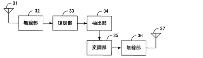
- FIG. 3 is a diagram showing the relay station 12 according to the first embodiment.
- the relay station 12 includes an antenna 31, a radio unit 32, a demodulation unit 33, an extraction unit 34, a modulation unit 35, a radio unit 36, and an antenna 37.
- the wireless unit 32 receives the first signal during the first period via the antenna 31.
- the radio unit 32 performs reception processing (processing related to RF (Radio Frequency)) to the first signal.
- the wireless unit 32 includes a power amplifier for amplifying the first signal, an analog-to-digital (AD) converter for converting an analog signal into a digital signal, a frequency converter for converting the frequency of the first signal, And a filter for extracting a predetermined frequency band from the signal.
- AD analog-to-digital
- the demodulation unit 33 demodulates the first signal that has been subjected to reception processing by the wireless unit 32.
- the extraction unit 34 is configured to extract a part of bits (m is 1 or more and less than n) from a plurality of bits (n (n is an integer of 2 or more) bits) included in the first signal demodulated by the demodulation unit 33. (Integer of) bits are extracted (decimating remaining (nm) bits).
- the extraction unit 34 generates a second signal including m bits.
- the modulation unit 35 modulates (maps) the second signal according to a modulation scheme that has a lower transmission rate than the modulation scheme of the first signal and a high error tolerance.
- the wireless unit 36 performs transmission processing (RF related processing) on the modulated second signal.
- the wireless unit 36 transmits the second signal to the receiving station 13 in the second period via the antenna 37.
- FIG. 4 is a diagram showing the receiving station 13 according to the first embodiment.
- the receiving station 13 includes an antenna 41, a wireless unit 42, a first storage unit 43, a second storage unit 44, and a demodulation unit 45.
- the wireless unit 42 receives a wireless signal via the antenna 41.
- the radio unit 42 performs reception processing (RF-related processing) on the received radio signal.
- the first storage unit 43 temporarily stores the first signal (direct wave) received from the transmitting station 11 in the first period.
- the second storage unit 44 temporarily stores the second signal received from the relay station 12 in the second period.
- the demodulation unit 45 first demodulates the second signal. Then, the demodulation unit 45 demodulates the first signal using the demodulation result of the second signal.
- the demodulation unit 45 can narrow down the search candidate points to signal point candidates in the case where the m bits included in the second signal are known. By doing this, it is possible to reduce the reception load of the receiving station 13 and to perform demodulation with high accuracy. Note that the demodulation unit 45 may determine the likelihood by using both m bits included in the second signal and m bits in n bits included in the first signal to demodulate the first signal. .
- FIG. 5 is a diagram showing the operation of the relay system.
- the transmitting station 11 transmits a first signal including n bits to the relay station 12 and the receiving station 13 in a first period.
- the relay station 12 demodulates a specific bit ((nm) bits) after demodulating the signal, remodulates the second signal including the remaining m bits, and transmits the second signal to the receiving station 13.
- the receiving station 13 combines the first signal received from the transmitting station 11 and the second signal received from the relay station 12 to demodulate a desired signal.
- FIG. 6 is a diagram showing a mapping method by gray mapping.
- the modulation scheme is 16 QAM
- the bit number n of the first signal is 4 bits
- the bit number m of the second signal is 2 bits
- the relay station 12 demodulates the signal point of the first signal, thins out 2 bits out of 4 bits, and relays (sends) the remaining 2 bits.
- the relay station 12 thins out the specific 2 bits rather than thinning out any 2 bits out of 4 bits.
- the relay station 12 determines that the minimum distance between the candidate signal points when all four bits (n bits) are unknown is a signal when the value of two bits (n-m bits) to be relayed is known. Extract 2 bits (m bits) so as to be longer than the minimum distance between candidate points. By doing this, the receiving station 13 can easily and accurately search the remaining 2 bits (nm bits) using the 2 bits (m bits) received from the relay station 12 .
- FIG. 7 is a diagram showing a search range of the first signal when the second signal is known.
- the relay station 12 thins out the first bit and the third bit from the left among the received 4-bit signals, and relays only the second bit 0 and the fourth bit 0.
- the relay station 12 may extract all odd-numbered (first and third) bits or all even-numbered (second and fourth) bits from the 4-bit signal.
- the relay station 12 relays 2 bits to be relayed using QPSK modulation that is more resistant to errors than 16 QAM. By doing this, the load on the link between the relay station 12 and the receiving station 13 is reduced. It is possible to increase the power per bit and transmit using a more error tolerant modulation scheme. Compared to the case of relaying all the bits (four bits) of the first signal, high transmission accuracy can be realized.
- the receiving station 13 determines that both the second bit and the fourth bit are 0 from the demodulation result of the 2-bit signal robustly transmitted from the relay station 12 by QPSK modulation.
- the receiving station 13 can narrow down the search candidate points of the first signal transmitted from the transmitting station 11 by using the decoding result of the second signal in which both the second bit and the fourth bit are 0. Become.
- the 16 candidates of the signal point of the first signal are narrowed to four points of the candidates 71 to 74 of four signal points.
- the demodulation unit 45 when the demodulation unit 45 combines the first signal from the 16 candidates of the signal point of the first signal, the 16 candidate minimum signal points of the signal point of the first signal The distance between them is 2/3.
- the demodulator 45 decodes the remaining (n ⁇ m) bits of the first signal from the four candidate signal points 71 to 74, the minimum distance between the signal points is 4/3.
- the extraction unit 34 thins out the specific (nm) bits from the first signal so as to increase the minimum distance between the signal points of the search candidate at the receiving station 13 as much as possible.
- the relay station 12 and the receiving station 13 share information on which m bits of the n bits the relay station 12 relays.
- the information on which m bits of n bits the relay station 12 relays may be the number of decimation bits or the decimation method (which number of bits should be decimated), and even if the decimation bit numbers match It may be a number of bits to be relayed.
- the information shared by the relay station 12 and the receiving station 13 may be notified to the receiving station 13 in advance by the relay station 12, or may be notified to the receiving station 13 together with the second signal.
- the number of bits to be decimated and the number of bits to be relayed at the relay station 12 are determined from the modulation scheme, the mapping method, and the trade-off between communication accuracy and line load. By reducing the number of decimated bits and relaying many bits, it is considered that the search candidate points of the remaining bits at the receiving station 13 are reduced and the distance between signal points is also increased, and the reception accuracy can be improved. The load on the link between the relay station 12 and the receiving station 13 is not much reduced.
- the number of bits to be skipped is increased and the number of bits to be relayed is reduced, the number of search candidates at the receiving station 13 is large, the distance between signal points is not very large, and transmission accuracy may be degraded compared to the case where the number of relay bits is large. There is. There is an advantage that the link load between the relay station 12 and the receiving station 13 is reduced.
- the optimal relay bit number m changes depending on the number of bits received at the relay station and the mapping method of the signal.
- the load on the link can be reduced by the demodulation unit 45 using the decoding result of the second signal to narrow the search candidate points of the first signal and increasing the minimum distance between the search candidate points (signal points).
- the transmission performance between the relay station and the receiving station can be improved. Even if the relay station 12 does not relay all the information (bits) included in the first signal, the receiving station 13 can robustly recover the signal. Robust transmission can be performed without performing encoding / decoding processing at the transmitting station 11 and the receiving station 13.
- the receiving station 13 can restore part of the information of the first signal by using the second signal robustly transmitted from the relay station 12, a search for restoring the first signal transmitted from the transmitting station 11 It is possible to narrow the number of points and to increase the distance between signal points to be searched.
- the relay station in accordance with the mapping method of the transmitting station 13 12 decimates specific bits and relays only the remaining bits to the receiving station 13. As a result, it is possible to solve the problems of the inefficiency of the channel and the processing burden on the receiving station 13 and to transmit the radio signal from the transmitting station 11 to the receiving station 13 with certainty.
- the relay station 12 can transmit the remaining bits to be relayed by a more robust mapping scheme because the number of bits included in the signal is reduced.
- mapping method is gray mapping
- other mapping methods may be used.
- the mapping method may be any method as long as the search candidate of the first signal can be limited using the demodulation result of the second signal.
- mapping methods other than gray mapping two examples are shown about mapping methods other than gray mapping.
- the first signal is 4 bits
- the number of decimated bits is 2 bits
- the second signal to be relayed is 2 bits.
- the extraction unit 34 thins out the upper 2 bits and extracts the lower 2 bits, whereby the minimum distance of the search candidate (signal point) of the first signal can be expanded.
- the mapping of the first signal In the first quadrant, the upper 2 bits are 00. In the second quadrant, the upper two bits are ten. In the third quadrant, the upper 2 bits are 11. In the fourth quadrant, the upper 2 bits are 01. Signal points whose lower 2 bits are 00 are indicated by gray-filled circles. Signal points whose lower 2 bits are 01 are indicated by vertical and horizontal cross-shaped circles. Signal points whose lower 2 bits are 10 are indicated by diagonal crosses. Signal points whose lower 2 bits are 11 are indicated by dotted circles.
- the demodulator 45 of the receiving station 13 sets candidate points for the search for the first signal as candidate points. It can be narrowed to 81-84. By doing this, it is possible to double the minimum distance of the search candidate (signal point) of the first signal.
- the demodulator 45 of the receiving station 13 sets candidate points for the search for the first signal as candidate points. It can be narrowed to 91-94. By doing this, it is possible to significantly increase the minimum distance of the search candidate (signal point) of the first signal.
- the receiving station 13 can narrow down the search candidate point (signal point) of the first signal as uniformly as possible using the demodulation result of the second signal. You can increase the minimum distance between them.
- Modification 2 In the first embodiment and its first modification, signals communicated by the transmitting station 11, the relay station 12, and the receiving station 13 are not encoded. However, the transmitting station 11, the relay station 12, and the receiving station 13 can encode signals to be communicated.
- the transmission station 11 may further include an encoding unit (not shown) that performs encoding of a convolutional code, a turbo code, or the like on the input transmission signal.
- the modulator 21 modulates the transmission signal encoded by the encoder.
- the receiving station 13 may further include a decoding unit (not shown) that decodes the demodulation result of the demodulation unit 45 by a method corresponding to the encoding unit of the transmission station 11.
- the decoding unit outputs the decoding result as a reception signal.
- the error resistance can be further enhanced.
- the relay station 12 can be realized, for example, as a semiconductor integrated circuit (chip). That is, the demodulation unit 33, the extraction unit 34, and the modulation unit 35 can be realized by one or more semiconductor integrated circuits.
- the one or more semiconductor integrated circuits perform signal input / output with the outside (antenna, other semiconductor integrated circuits, radio unit, firmware, etc.) via the connector pins.
- the receiving station 13 can be realized, for example, as a semiconductor integrated circuit (chip). That is, the first storage unit 43, the second storage unit 44, and the demodulation unit 45 can be realized by one or more semiconductor integrated circuits.
- the one or more semiconductor integrated circuits perform signal input / output with the outside (antenna, other semiconductor integrated circuits, radio unit, firmware, etc.) via the connector pins.
Landscapes
- Engineering & Computer Science (AREA)
- Computer Networks & Wireless Communication (AREA)
- Signal Processing (AREA)
- Radio Relay Systems (AREA)
Abstract
送信装置から受信装置へ直接送信される無線信号を中継する中継装置は、送信装置から第1信号を受信する受信部(32、33)と、第1信号に含まれるn個のビットから、m個のビットを抽出する抽出34と、m個のビットを含む第2信号を受信装置へ送信する送信部(35、36)とを備える部ことを特徴とする。
Description
本発明は、無線信号の中継に関する。
送信局(送信元)と受信局(宛先)との間に無線信号を中継する中継局を配置した中継システムが注目されている。AF(Amplitude and Forward)方式では、中継局は、送信局からの信号を復調せずに増幅だけしてそのまま受信局へ送信(中継)する。DF(Decode and Forward)方式では、中継局は、送信局からの信号を復調し再度符号化して受信局へ送信(中継)する。
非特許文献1では、AF、DF方式で、受信局が、送信局から直接送信された信号と、中継局から中継された信号との両方を用いて、空間ダイバーシチ効果により通信品質を向上させる技術(協調通信や協力通信)が開示されている。
しかしながら、非特許文献1に開示される技術では、中継局によって中継される信号が、リンクの負荷を増大させ、また受信局側の受信処理の負荷を増大させるとの問題があった。
J.N.Laneman他,"Cooperative diversity in wireless networks: efficient protocols and outage behavior," IEEE Transactions on Information Theory,Vol.50,pp.3062-3080,Dec.2004.
この発明の課題の1つは、受信局側の受信処理の負荷を低減させながら、協調通信を可能とする中継装置を提供することである。
上記鑑みて、本発明の一実施の形態に係る中継装置は、送信装置から受信装置へされる無線信号を中継する中継装置であって、前記無線信号を受信して第1信号を取り出す受信部と、前記第1信号に含まれるn(nは2以上の整数)個のビットから、m(mは1以上n未満の整数)個のビットを抽出する抽出部と、前記m個のビットを含む第2信号を、前記受信装置へ送信する送信部とを備えることを特徴とする。
本発明によれば、受信局側の受信処理の負荷を低減させながら、協調通信を可能とする。
以下、本発明の実施形態について説明する。
(第1の実施形態)
図1は、第1の実施形態に係る中継システムを示す図である。中継システムは、送信局11と中継局12と受信局13とを備える。送信局11は、第1期間(第1スロット)で第1信号を受信局13へ(直接)送信する。受信局13と中継局12は、第1期間に、第1信号を受信する。第1信号の宛先アドレスは、受信局13のアドレスである。中継局12は、中継先を特定する中継先情報(例えば、受信局13のアドレス)を予め保持する。中継局12は、1つ以上の中継先情報のいずれかと、受信した信号の宛先とが合致する場合に、受信した信号を中継する。中継局12は、第1期間のあと、第2期間(第2スロット)で、第1信号から情報量を削減して(間引いて)生成した第2信号を受信局13へ送信(中継)する。受信局13は、第2期間に、第2信号を受信する。受信局13は、送信局11から受信した第1信号と中継局12から受信した第2信号とを合成して復調する。
図1は、第1の実施形態に係る中継システムを示す図である。中継システムは、送信局11と中継局12と受信局13とを備える。送信局11は、第1期間(第1スロット)で第1信号を受信局13へ(直接)送信する。受信局13と中継局12は、第1期間に、第1信号を受信する。第1信号の宛先アドレスは、受信局13のアドレスである。中継局12は、中継先を特定する中継先情報(例えば、受信局13のアドレス)を予め保持する。中継局12は、1つ以上の中継先情報のいずれかと、受信した信号の宛先とが合致する場合に、受信した信号を中継する。中継局12は、第1期間のあと、第2期間(第2スロット)で、第1信号から情報量を削減して(間引いて)生成した第2信号を受信局13へ送信(中継)する。受信局13は、第2期間に、第2信号を受信する。受信局13は、送信局11から受信した第1信号と中継局12から受信した第2信号とを合成して復調する。
図2は、第1の実施形態に係る送信局11を示す図である。送信局11は、変調部21と、無線部22と、アンテナ23とを備える。送信信号は、図示しない上位層処理部で生成される。変調部21は、送信信号を、変調方式に従って変調(マッピング)する。無線部22は、変調された送信信号に、送信処理(RF(Radio Frequency)関連の処理)を行う。無線部22は、送信信号から所定の周波数帯域を抽出するフィルタと、送信信号の周波数を変換する周波数変換器と、デジタル信号をアナログ信号へ変換するDA(Digital-to-Analog)変換器と、送信信号を増幅する電力増幅器とを備える。無線部22は、アンテナ23を介して、第1期間に送信信号を送信する。
図3は、第1の実施形態に係る中継局12を示す図である。中継局12は、アンテナ31と、無線部32と、復調部33と、抽出部34と、変調部35と、無線部36と、アンテナ37とを備える。無線部32は、アンテナ31を介して、第1期間中に第1信号を受信する。無線部32は、第1信号に、受信処理(RF(Radio Frequency)関連の処理)を行う。無線部32は、第1信号を増幅する電力増幅器と、アナログ信号をデジタル信号へ変換するAD(Analog-to-Digital)変換器と、第1信号の周波数を変換する周波数変換器と、第1信号から所定の周波数帯域を抽出するフィルタとを備える。復調部33は、無線部32で受信処理がなされた第1信号を、復調する。抽出部34は、復調部33で復調された第1信号に含まれる複数のビット(n(nは2以上の整数)個のビット)から、一部のビット(m(mは1以上n未満の整数)個のビット)を抽出する(残りの(n-m)ビットを間引く)。抽出部34は、m個のビットを含む第2信号を生成する。変調部35は、第2信号を、第1信号の変調方式よりも伝送レートが低く誤り耐性の強い変調方式によって変調(マッピング)する。無線部36は、変調された第2信号に、送信処理(RF関連の処理)を行う。無線部36は、アンテナ37を介して、第2期間に、第2信号を受信局13へ送信する。
図4は、第1の実施形態に係る受信局13を示す図である。受信局13は、アンテナ41と、無線部42と、第1記憶部43と、第2記憶部44と、復調部45とを備える。無線部42は、アンテナ41を介して、無線信号を受信する。無線部42と、受信した無線信号に、受信処理(RF関連の処理)を行う。第1記憶部43は、第1期間に、送信局11から受信した第1信号(直接波)を一時的に記憶する。第2記憶部44は、第2期間に、中継局12から受信した第2信号を一時的に記憶する。復調部45は、まず、第2信号を復調する。そして、復調部45は、次に、第2信号の復調結果を用いて、第1信号を復調する。復調部45は、第2信号に含まれるm個のビットを既知とした場合の信号点の候補に探索候補点を絞ることができる。このようにすることで、受信局13の受信負荷を低減するとともに、精度の高い復調が可能となる。なお、復調部45は、第2信号に含まれるmビットと、第1信号に含まれるnビット中のmビットとの双方を用いて、尤度判定し、第1信号を復調してもよい。
図5は、中継システムの動作を示す図である。送信局11は、第1期間で、nビットを含む第1信号を、中継局12と、受信局13へ送信する。中継局12は、信号を復調した後に特定のビット((n-m)ビット)を間引き、残りのmビットを含む第2信号を再度変調して、受信局13へ送信する。受信局13は、送信局11から受信した第1信号と、中継局12から受信した第2信号を合成して、所望の信号を復調する。
以下では、第1信号のマッピング方法として、グレイマッピングを採用した場合を考える。このマッピング方法は、汎用的に用いられる直交振幅変調(Quadrature Amplitude Modulation、以下QAM)で適用可能である。
図6は、グレイマッピングでマッピング方法を示す図である。以下では、変調方式を16QAMとし、第1信号のビット数nを4ビットとし、第2信号のビット数mを2ビットとした例で説明する。
中継局12は、第1信号の信号点を復調して、4ビット中2ビットを間引いて残りの2ビットを中継(送信)する。中継局12は、4ビット中の任意の2ビットを間引くのではなく、特定の2ビットを間引く。中継局12は、4ビット(nビット)のすべてが未知とした場合の信号点の候補間の最小距離が、中継する2ビット(n-mビット)の値が既知であるとした場合の信号点の候補間の最小距離よりも、長くなるように、2ビット(mビット)を抽出する。このようにすることで、受信局13は、中継局12から受信する2ビット(mビット)を用いて、残りの2ビット(n-mビット)の探索を容易かつ高精度に行うことができる。
図7は、第2信号を既知とした場合の第1信号の探索範囲を示す図である。この例では、中継局12は、受信した4ビットの信号のうち、左から1ビット目と3ビット目の信号を間引き、2ビット目の0と4ビット目の0のみを中継する。中継局12は、4ビットの信号のうち、奇数番目(1番目、3番目)のビットすべてを抽出するか、偶数番目(2番目、4番目)のビットすべてを抽出してもよい。
中継局12は、中継する2ビットを、16QAMよりも誤り耐性の強いQPSK変調を用いて中継する。このようにすることで、中継局12と受信局13間のリンクへの負荷が軽減される。より誤り耐性の強い変調方式を用いて、ビットあたりの電力を高めて伝送することが可能となる。第1信号のすべてのビット(4ビット)を中継する場合と比べ、高い伝送精度を実現できる。
受信局13は、中継局12からQPSK変調でロバストに送られた2ビットの信号の復調結果から、2番目のビットと4番目のビットが共に0であることを決定する。受信局13は、2番目のビットと4番目のビットが共に0との第2信号の復号結果を用いることで、送信局11から送られた第1信号の探索候補点を絞ることが可能となる。図7の例では、第1信号の信号点の16個の候補から、4つの信号点の候補71~74の4点に絞られる。
図7に示すように、復調部45が、第1信号の信号点の16個の候補から第1信号を複合する際には、第1信号の信号点の16個の候補の最小の信号点間の距離は2/3である。一方、復調部45が、4つの信号点の候補71~74から第1信号の残りの(n-m)ビットを復号する際には、最小の信号点間の距離は4/3である。このように、抽出部34は、受信局13での探索候補の信号点間の最小距離をできるだけ大きくするように、第1信号から特定の(n-m)ビットを間引く。
中継局12と、受信局13とは、中継局12がnビット中のいずれのmビットを中継するかについての情報を共有する。中継局12がnビット中のいずれのmビットを中継するかについての情報は、間引くビット数や間引き方(何番目のビットを間引くのか)であっても良く、間引くビットの番号で合っても良く、中継するビットの番号であっても良い。この中継局12と受信局13とで共有される情報は、中継局12が予め受信局13へ通知しても良く、中継局12が第2信号とともに受信局13へ通知しても良い。
中継局12で何ビットを間引き、何ビットを中継するかは、変調方式、マッピング方法、および通信精度と回線の負荷のトレードオフから決定される。間引くビットを少なくし、多くのビットを中継すれば、受信局13での残りのビットの探索候補点は少なくなり、かつ信号点間距離も大きくなると考えられ、受信精度を向上できる。中継局12と受信局13間のリンクにかかる負荷はあまり軽減されない。
一方で、間引くビットを増やし、中継するビットを減らせば、受信局13での探索候補も多く、信号点間距離があまり大きくならず、中継ビット数が多い場合に比べて伝送精度が劣化するおそれがある。中継局12と受信局13間のリンク負荷が軽減されるという利点がある。
最適な中継ビット数mは、中継局で受信したビット数や信号のマッピング方法によって変化する。復調部45が第2信号の復号結果を用いて第1信号の探索候補点を絞り、探索候補点(信号点)間の最小距離を大きくすることで、リンクにかかる負荷を軽減することができ、中継局-受信局間の伝送性能を改善できる。中継局12が第1信号に含まれるすべての情報(ビット)を中継しなくても、受信局13は、ロバストに信号を復元できる。送信局11及び受信局13で符号化・復号化処理を行わずとも、ロバストな伝送が可能となる。受信局13は、中継局12からロバストに送られた第2信号を用いて、第1信号の情報の一部を復元できるため、送信局11から送られた第1信号を復元する際の探索点の数を絞り、かつ探索する信号点間の距離を広くとることが可能となる。
送信局11から受信局13へ直接送られた第1信号と、中継局12により中継された大2信号とのダイバーシチにより受信精度を高める協力通信において、送信局13のマッピング方法に合わせて中継局12が特定のビットを間引き、残りのビットだけを受信局13に中継する。これにより、回線の非効率性や受信局13の処理負担の問題を解消し、送信局11から受信局13へ、確実に無線信号を送信することができる。
送信局11から中継局12と受信局13、及び、中継局12から受信局13とすべてのリンクで同一の変調方式(16QAM)により第1信号すべて(4ビットの信号)を送る従来の方法に比べて、リンクにかかる負荷を軽減することができ、中継局-受信局間の伝送性能を改善することができる。中継局12は、中継する残りのビットを、信号に含まれるビット数が減少したため、よりロバストなマッピング方式によって送信できる。
(変形例1)
第1の実施形態では、第1信号のマッピング方法がグレイマッピングである例を示したが、その他のマッピング方法であってもよい。マッピング方法は、第2信号の復調結果を用いて、第1信号の探索候補を限定できればどのようなものであっても良い。以下に、グレイマッピング以外のマッピング方法について、2つの例を示す。
第1の実施形態では、第1信号のマッピング方法がグレイマッピングである例を示したが、その他のマッピング方法であってもよい。マッピング方法は、第2信号の復調結果を用いて、第1信号の探索候補を限定できればどのようなものであっても良い。以下に、グレイマッピング以外のマッピング方法について、2つの例を示す。
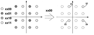
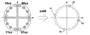
図8、図9に示すマッピングの例では、第1信号を4ビット、間引くビット数を2ビット、中継する第2信号を2ビットとする。ここで、抽出部34が上位2ビットを間引き、下位2ビットを抽出することで、第1信号の探索候補(信号点)の最小距離を拡大することができる。
図8、図9は、第1信号のマッピングを示す図である。第1象限では上位2ビットは00である。第2象限では上位2ビットは10である。第3象限では上位2ビットは11である。第4象限では上位2ビットは01である。下位2ビットが00である信号点は、灰色で塗りつぶされた丸で示す。下位2ビットが01である信号点は、縦横の十字模様の丸で示す。下位2ビットが10である信号点は、斜めの十字模様の丸で示す。下位2ビットが11である信号点は、点々模様の丸で示す。
図8の例では、第2信号の復号結果(3番目のビットが0、4番目のビットが0)を用いることで、受信局13の復調部45は、第1信号の探索候補を候補点81~84に絞ることができる。このようにすることで、第1信号の探索候補(信号点)の最小距離を2倍に長くする事ができる。
図9の例では、第2信号の復号結果(3番目のビットが0、4番目のビットが0)を用いることで、受信局13の復調部45は、第1信号の探索候補を候補点91~94に絞ることができる。このようにすることで、第1信号の探索候補(信号点)の最小距離を大幅に長くする事ができる。中継局12が特定のビットを間引くことで、受信局13が第2信号の復調結果を用いて、第1信号の探索候補点(信号点)ができるだけ均一に絞りこむことができ、探索候補点間の最小距離を長くできる。
(変形例2)
第1の実施形態及びその変形例1では、送信局11、中継局12、受信局13で通信される信号は、符号化されていない。しかし、送信局11、中継局12、受信局13は、通信する信号を、符号化することができる。
第1の実施形態及びその変形例1では、送信局11、中継局12、受信局13で通信される信号は、符号化されていない。しかし、送信局11、中継局12、受信局13は、通信する信号を、符号化することができる。
送信局11は、入力される送信信号に対して、畳み込み符号やターボ符号などの符号化を行う符号化部(図示せず)をさらに有していても良い。変調部21は、符号化部によって符号化された送信信号を変調する。
受信局13は、復調部45の復調結果を、送信局11の符号化部に対応する方式で復号する復号部(図示せず)をさらに有していても良い。復号部は、復号結果を受信信号として出力する。
このように、送信局11が送信する信号を符号化し、受信局13が受信した信号を復号することで、誤り耐性をさらに高めることができる。
なお、中継局12は、例えば、半導体集積回路(チップ)として実現することができる。即ち、復調部33と、抽出部34と、変調部35とを、1つまたは複数の半導体集積回路で実現できる。この1つまたは複数の半導体集積回路は、コネクタピンを介して、外部(アンテナや、他の半導体集積回路、無線部、ファームウェアなど)と信号の入出力を行う。
なお、受信局13は、例えば、半導体集積回路(チップ)として実現することができる。即ち、第1記憶部43と、第2記憶部44と、復調部45とを、1つまたは複数の半導体集積回路で実現できる。この1つまたは複数の半導体集積回路は、コネクタピンを介して、外部(アンテナや、他の半導体集積回路、無線部、ファームウェアなど)と信号の入出力を行う。
(その他の実施形態)
本発明の実施形態は上記の実施形態に限られず拡張、変更可能であり、拡張、変更した実施形態も本発明の技術的範囲に含まれる。
本発明の実施形態は上記の実施形態に限られず拡張、変更可能であり、拡張、変更した実施形態も本発明の技術的範囲に含まれる。
11:送信局、12:中継局、13:受信局、21:変調部、22:無線部、23:アンテナ、31:アンテナ、32:無線部、33:復調部、34:抽出部、35:変調部、36:無線部、37:アンテナ、41:アンテナ、42:無線部、43:第1記憶部、44:第2記憶部、45:復調部、71~74、81~84、91~94:候補点
Claims (5)
- 送信装置から受信装置へされる無線信号を中継する中継装置であって、
前記無線信号を受信して第1信号を取り出す受信部と、
前記第1信号に含まれるn(nは2以上の整数)個のビットから、m(mは1以上n未満の整数)個のビットを抽出する抽出部と、
前記m個のビットを含む第2信号を、前記受信装置へ送信する送信部とを備えることを特徴とする中継装置。 - 前記抽出部は、前記第1信号の変調方式での信号点配置において、前記n個のビットのすべてが未知とした場合の信号点の候補間の最小距離が、前記n個のビットのうち前記m個のビットの値が既知であるとした場合の信号点の候補間の最小距離よりも、長くなるように、前記m個のビットを抽出し、
前記送信部は、前記第1信号の変調方式よりも伝送レートの低い変調方式で、前記第2信号を送信することを特徴とする請求項1に記載の中継装置。 - 前記第1信号が送信される際の信号点配置はグレイマッピングであり、
前記抽出部は、前記n個のビットの偶数番目のみを抽出するか、前記n個のビットの奇数番目のみを抽出することを特徴とする請求項2の記載の中継装置。 - 前記送信部は、前記n個のビット中のいずれの前記m個のビットを中継するかについての情報を、前記受信装置へ送信することを特徴とする請求項3に記載の中継装置。
- 前記第1信号と前記第2信号とは、前記受信装置によって受信され、
前記第1信号は、前記受信装置によって、前記第2信号に含まれる前記m個のビットが既知とされた場合の信号点の候補に探索候補点を絞って、復調されることを特徴とする中継装置。
Priority Applications (1)
| Application Number | Priority Date | Filing Date | Title |
|---|---|---|---|
| PCT/JP2009/004186 WO2011024226A1 (ja) | 2009-08-28 | 2009-08-28 | 中継装置 |
Applications Claiming Priority (1)
| Application Number | Priority Date | Filing Date | Title |
|---|---|---|---|
| PCT/JP2009/004186 WO2011024226A1 (ja) | 2009-08-28 | 2009-08-28 | 中継装置 |
Publications (1)
| Publication Number | Publication Date |
|---|---|
| WO2011024226A1 true WO2011024226A1 (ja) | 2011-03-03 |
Family
ID=43627356
Family Applications (1)
| Application Number | Title | Priority Date | Filing Date |
|---|---|---|---|
| PCT/JP2009/004186 Ceased WO2011024226A1 (ja) | 2009-08-28 | 2009-08-28 | 中継装置 |
Country Status (1)
| Country | Link |
|---|---|
| WO (1) | WO2011024226A1 (ja) |
-
2009
- 2009-08-28 WO PCT/JP2009/004186 patent/WO2011024226A1/ja not_active Ceased
Non-Patent Citations (3)
| Title |
|---|
| "Adaptive demodulation using rateless erasure codes", IEEE TRANSACTIONS ON COMMUNICATIONS, September 2006 (2006-09-01), pages 1574 - 1585 * |
| "IEEE 69th Vehicular Technology Conference, 2009., 2009.04.26", article KANDASAMY ILLANKO ET AL.: "Cooperative Communication Using Bit-Selective Adaptive Demodulation and Raptor Codes: The Gaussian Relay Channel Case", pages: 1 - 7 * |
| J.NICHOLAS LANEMAN ET AL.: "Cooperative diversity in wireless networks: Efficient protocols and outage behavior", IEEE TRANSACTIONS ON INFORMATION THEORY, vol. 50, no. ISSUE1, December 2004 (2004-12-01), pages 062 - 3080 * |
Similar Documents
| Publication | Publication Date | Title |
|---|---|---|
| KR100963410B1 (ko) | 릴레이 시스템에서 신호점 재배열 또는 중첩 변조를 기반으로 하는 협력 수신 다이버시티 장치 및 방법 | |
| CN101843008B (zh) | 网络编码方法和网络编码装置 | |
| CN101958766B (zh) | 一种基于源端网络编码和交替传输的中继协作方法 | |
| KR100973671B1 (ko) | 광대역 무선통신시스템에서 중계 장치 및 방법 | |
| JPWO2012120743A1 (ja) | 中継装置および中継補助装置 | |
| JP2018515956A5 (ja) | ||
| CA2809886C (en) | Generation and application of a sub-codebook of an error control coding codebook | |
| Ghannam et al. | Experimental demonstration of spectrally efficient frequency division multiplexing transmissions at E-Band | |
| US7756473B2 (en) | Apparatus and method of on-channel repeater | |
| CN103138892B (zh) | 基于阶梯调制的自适应中继通信方法 | |
| JPWO2010095267A1 (ja) | 衛星通信システムおよびデータ伝送方法 | |
| CN109302266B (zh) | 基于双层网络编码的高能效协作中继网络传输方法 | |
| CN102986181B (zh) | 一种微波信号的校正方法、装置和系统 | |
| KR100940217B1 (ko) | 무선통신시스템에서 다중 안테나를 이용한 중계 장치 및방법 | |
| CN102497250B (zh) | 多址接入信道下自适应编码中继系统与方法 | |
| CN101686215B (zh) | 一种信号编码调制方法及装置 | |
| CN103716278B (zh) | 中继通信系统中的分层传输 | |
| KR100964610B1 (ko) | 오류정정 부호를 이용한 다이버시티 방법 | |
| US8331423B2 (en) | Relaying apparatus and method in wireless communication system | |
| CN102369672A (zh) | 生成软比特的系统和方法 | |
| JP6892301B2 (ja) | 無線通信システム、移動局および基地局 | |
| WO2009113763A1 (en) | Cooperative reception diversity apparatus and method based on signal point rearrangement or superposition modulation in relay system | |
| JP6250676B2 (ja) | 協調送信の方法、信号、ソースエンティティ、中継エンティティ、受信方法、宛先エンティティ、システム、及びそれらに対応するコンピュータプログラム | |
| WO2022085136A1 (ja) | 送受信システム及び送受信方法 | |
| JP6526838B2 (ja) | 中継/通信局装置 |
Legal Events
| Date | Code | Title | Description |
|---|---|---|---|
| 121 | Ep: the epo has been informed by wipo that ep was designated in this application |
Ref document number: 09848677 Country of ref document: EP Kind code of ref document: A1 |
|
| NENP | Non-entry into the national phase |
Ref country code: DE |
|
| 122 | Ep: pct application non-entry in european phase |
Ref document number: 09848677 Country of ref document: EP Kind code of ref document: A1 |
|
| NENP | Non-entry into the national phase |
Ref country code: JP |