WO2011007873A1 - ニードル移動装置 - Google Patents
ニードル移動装置 Download PDFInfo
- Publication number
- WO2011007873A1 WO2011007873A1 PCT/JP2010/062077 JP2010062077W WO2011007873A1 WO 2011007873 A1 WO2011007873 A1 WO 2011007873A1 JP 2010062077 W JP2010062077 W JP 2010062077W WO 2011007873 A1 WO2011007873 A1 WO 2011007873A1
- Authority
- WO
- WIPO (PCT)
- Prior art keywords
- needle
- motor
- moving
- signal
- drive motor
- Prior art date
- Legal status (The legal status is an assumption and is not a legal conclusion. Google has not performed a legal analysis and makes no representation as to the accuracy of the status listed.)
- Ceased
Links
Images

Classifications
-
- G—PHYSICS
- G01—MEASURING; TESTING
- G01N—INVESTIGATING OR ANALYSING MATERIALS BY DETERMINING THEIR CHEMICAL OR PHYSICAL PROPERTIES
- G01N35/00—Automatic analysis not limited to methods or materials provided for in any single one of groups G01N1/00 - G01N33/00; Handling materials therefor
- G01N35/10—Devices for transferring samples or any liquids to, in, or from, the analysis apparatus, e.g. suction devices, injection devices
- G01N35/1009—Characterised by arrangements for controlling the aspiration or dispense of liquids
- G01N35/1011—Control of the position or alignment of the transfer device
-
- G—PHYSICS
- G01—MEASURING; TESTING
- G01N—INVESTIGATING OR ANALYSING MATERIALS BY DETERMINING THEIR CHEMICAL OR PHYSICAL PROPERTIES
- G01N35/00—Automatic analysis not limited to methods or materials provided for in any single one of groups G01N1/00 - G01N33/00; Handling materials therefor
- G01N35/10—Devices for transferring samples or any liquids to, in, or from, the analysis apparatus, e.g. suction devices, injection devices
- G01N35/1081—Devices for transferring samples or any liquids to, in, or from, the analysis apparatus, e.g. suction devices, injection devices characterised by the means for relatively moving the transfer device and the containers in an horizontal plane
- G01N35/109—Devices for transferring samples or any liquids to, in, or from, the analysis apparatus, e.g. suction devices, injection devices characterised by the means for relatively moving the transfer device and the containers in an horizontal plane with two horizontal degrees of freedom
Definitions
- the present invention relates to a needle moving device that moves a needle (needle) to a designated position.
- a needle moving device is an autosampler that performs sampling by moving the needle to a specified sample container position, or moves the needle to a predetermined position and drops the eluate from the liquid chromatograph at that position. Applies to fraction collectors.
- the “needle” is not limited to a needle-like member that is inserted into a sample container and sucks a liquid, but includes a needle that just drops a liquid.
- a needle moving device for moving a needle to a designated position is generally configured to move the needle in two directions perpendicular to each other in a horizontal plane direction.
- the needle moving device includes a mechanism for moving the needle in each direction by driving a pulse motor, and the needle moves in each direction by a distance corresponding to a pulse signal applied to each pulse motor (see, for example, Patent Document 1). .
- the drive of the needle is generally controlled by a system controller.
- a system controller capable of inputting / outputting and displaying information is connected to the system controller, and the operator is configured to be able to manage the operation of the device including the needle moving device via the personal computer.
- an apparatus that performs sampling or dispensing by actually moving a needle such as an autosampler or a fraction collector, is defined as an execution apparatus.
- a device such as a system controller that is connected to the execution device and controls the operation of the execution device is defined as an arithmetic processing device.
- the needle when the needle is in contact with an obstacle and prevented from moving, the needle may not move normally to the position designated by the operator.
- an operation such as sampling is performed at a position where the needle is stopped, sampling is performed on a sample container which is not intended by the operator, or the tip of the needle protrudes from a position where there is no sample container. Problems such as bending may occur. Therefore, it is important to be able to recognize when the needle has not moved to the position designated by the operator.
- a pulse motor for moving the needle in each direction is provided with an encoder that can measure the moving distance of the needle from the number of rotations of the pulse motor.
- the signal from the encoder can be compared with the signal from the arithmetic processing device, and it can be confirmed whether or not the needle has been moved normally by checking whether or not they match.
- the signal given from the arithmetic processing unit to the execution unit may change to a signal different from that based on information input by the operator.
- the needle moves according to the changed signal from the arithmetic processing unit, the needle moves to a position different from the designated position, but it is recognized in the execution unit that the needle has moved normally. That is, in the above method, even if the signal given from the arithmetic processing unit to the execution unit changes, the abnormality cannot be detected. Conventionally, since the case where the signal given to the execution device changes is not taken into consideration, it has not been possible to recognize that the signal given to the execution device has changed.
- an object of the present invention is to provide a needle moving device that can detect an abnormality even when a signal given from an arithmetic processing unit to an execution unit changes.
- the present invention includes a needle, a needle driving unit for moving the needle at least in the horizontal plane by driving the motor, and an encoder provided in the motor for measuring the moving distance of the needle based on the number of rotations of the motor.
- An execution device that outputs a signal
- an arithmetic processing device that is connected to the execution device and that gives the execution device a signal for moving the needle to a position specified by information input from the outside, and is provided in the arithmetic processing device for execution
- a determination unit that receives a measurement signal from the encoder output by the apparatus, obtains the position of the needle after movement, compares it with a designated position, and determines whether or not they match.
- the needle drive unit includes an X-direction drive motor and a Y-direction drive motor for moving the needle in the X and Y directions orthogonal to each other in the horizontal plane as the motor, and an X-direction drive motor as the encoder And the Y direction drive motor are provided with respective encoders, and the determination unit is a position designated by obtaining the needle position in the horizontal plane based on signals from both encoders provided in the X direction drive motor and the Y direction drive motor.
- the example which is what is compared with can be given.
- the execution device includes means (signal processing unit 6 in the embodiment) for detecting whether or not the driven needle has reached a designated position based on a measurement signal from the encoder and a signal given from the arithmetic processing device. It is preferable. If the execution device cannot detect that the needle has reached the designated position, it can be determined that the execution device could not move normally due to a physical failure such as contact with an obstacle. Therefore, by providing such execution means in the execution device, the cause when the needle could not be moved to the designated position is on the execution device side or given from the arithmetic processing device to the execution device. It can be determined whether the signal is present.
- a determination unit that receives a measurement signal from the encoder output from the execution device, obtains the position of the needle after movement, and determines whether or not it matches the specified position is provided in the arithmetic processing device. Since it is provided, it can be determined on the arithmetic processing unit side whether or not the needle has been moved normally. That is, the determination unit determines whether the movement of the needle is normal or abnormal on the basis of information at a stage before being transmitted from the arithmetic processing device to the execution device, so that the signal from the arithmetic processing device to the execution device changes Can recognize it as abnormal.
- the needle moving device includes an autosampler 1a as an execution device and a system controller 1b as an arithmetic processing device.
- a personal computer 17 Connected to the system controller 1b is a personal computer 17 which is a device for inputting / outputting information and displaying information.
- the autosampler 1a has a needle 2.
- the needle 2 can be moved in the horizontal plane direction and the vertical direction by the drive unit 4.
- the tip of the needle 2 is connected to the syringe pump 9, and by operating a pump drive motor 8 that drives the plunger of the syringe pump 9, liquid can be sucked and discharged from the tip.
- the drive unit 4 includes an X-direction drive motor 4a and a Y-direction drive motor 4b for moving the needle 2 in the X and Y directions orthogonal to each other in a horizontal plane, and a Z-direction drive motor 4c for moving in the vertical direction.
- Each of the drive motors 4a, 4b and 4c is, for example, a pulse motor, and operates according to a pulse signal from the signal processing unit 6.
- the X-direction drive motor 4a and the Y-direction drive motor 4b are provided with encoders 12a and 12b.
- the encoders 12a and 12b can measure the moving distance of the needle 2 in each direction from the rotational speeds of the motors 4a and 4b.
- the signal processing unit 6 supplies a pulse signal corresponding to the signal given from the arithmetic processing device 1b to each drive motor 4a, 4b, 4c and the pump drive motor 8.
- the system controller 1b includes an arithmetic processing unit 16, a storage unit 18, and a determination unit 20.
- the arithmetic processing unit 16 inputs information related to sampling input via the personal computer 17, and controls the operation of the autosampler 1a according to the information.
- the information input by the operator via the personal computer 17 is, for example, the number of the sample container to be sampled, and includes the order when sampling is performed on a plurality of sample containers.
- a plurality of sample containers containing samples to be sampled by the autosampler are arranged in a rack provided below the needle 2.
- Information on the position where each sample container is arranged is input in advance via the personal computer 17, and the information is stored in, for example, the storage unit 18 of the system controller 1b or the storage device in the personal computer 17. In this embodiment, it is assumed that the data is stored in the storage unit 18 of the system controller 1b.
- the arithmetic processing unit 16 specifies the position where the designated sample container is arranged based on the information stored in the storage unit 18, and gives the position information to the signal processing unit 6 of the autosampler 1a. ing. When a plurality of sample containers to be sampled and the order are designated in advance, the position where the next sample container to be sampled is specified along the order, and the position information is obtained from the autosampler 1a.
- the signal processing unit 6 is provided.
- the determination unit 20 receives signals from the encoders 4a and 4b, obtains the position of the needle 2 after movement from these signals, compares the obtained position of the needle 2 with the designated position, and the two match. Whether or not.
- the arithmetic processing unit 16 receives information on the determination result from the determination unit 20 and controls the subsequent operation of the autosampler 1a based on the information.
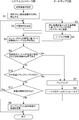
- FIG. 2 is a flowchart showing the operation of this embodiment. The operation of this embodiment will be described with reference to FIG.
- the arithmetic processing unit 16 of the system controller 1b specifies the sample container designated from the information on the arrangement position of the sample container stored in the storage unit 18. The position is specified (step S1), and the information is transmitted to the autosampler 1a side (step S2).
- the signal processing unit 6 gives a pulse signal to the X direction drive motor 4a and the Y direction drive motor 4b based on the information given from the arithmetic processing unit 16 (step S3), and moves the needle 2 (step S3).
- Step S4 the encoder 12a measures the moving distance in the X direction of the needle 2 from the rotational speed of the X direction driving motor 4a, and the encoder 12b determines the moving distance in the Y direction of the needle 2 from the rotational speed of the Y direction driving motor 4b. measure. It is assumed that the needle 2 has been returned to the home position before the signal for moving the needle 2 is given from the system controller 1b.
- the determination unit 20 specifies the position of the moved needle 2 based on the signals from the encoders 12a and 12b (step S5), and designates the position of the needle 2 after the movement. It is determined whether or not the position of the sample container thus obtained matches (step S6).
- the determination result by the determination unit 20 is input to the arithmetic processing unit 16.
- the arithmetic processing unit 16 gives a signal for performing sampling in that state to the autosampler 1a side.
- sampling is performed in accordance with the sampling start signal from the arithmetic processing unit 16 (step S7).
- a pulse signal is given from the signal processing unit 6 to the Z-direction drive motor 4c so that the needle 2 is lowered by a certain distance and the tip is inserted into the sample container.
- a pulse signal is given to the pump drive motor 8 so that a predetermined amount of sample is aspirated by 9.
- the needle 2 is returned to the home position (step S8).
- the sampled sample container information is stored in the storage unit 18 on the system controller 1b side.
- the arithmetic processing unit 16 performs an operation by, for example, displaying on the display of the personal computer 17 whether or not to perform sampling at that position. Check with the person and ask for judgment. When sampling is performed as it is, a sampling start signal is given to the autosampler 1a side, and the operations in steps S7 to S9 are continued.
- a function for requesting the operator to determine whether or not to perform sampling at that position may not be provided.
- step S11 it is determined whether or not to retry the movement of the needle 2 (step S11). Whether or not to retry the movement of the needle 2 is determined by, for example, displaying a confirmation message on the display of the personal computer 17. If the number of retries is set in advance, the retry is repeated for that number of times.
- step S2 the position information of the designated sample container is transmitted again from the arithmetic processing unit 16 to the autosampler 1a side (step S2).
- the abnormality in the movement of the needle 2 detected by the determination of the determination unit 20 is caused by the abnormality in the signal given from the system controller 1b to the autosampler 1a. This is because the problem may be solved by transmitting.
- signals from the encoders 12a and 12b are also input to the signal processing unit 6.
- the position of the needle 2 after the movement is specified based on the signals from the encoders 12a and 12b, and whether or not it matches the information on the position of the sample container given from the arithmetic processing unit 16. This is because it can be confirmed. If they do not match, it can be determined that the needle 2 could not move normally due to a physical malfunction such as contact with an obstacle.
- the determination unit when an abnormality in the movement of the needle 2 is detected by the determination at 20, it can be determined that there is an abnormality in the signal given from the system controller 1b to the autosampler 1a. In this way, if not only the determination unit 20 but also the signal processing unit 6 can detect abnormal movement of the needle 2 using the signals from the encoders 12a and 12b, the abnormal movement of the needle 2 is detected. It is possible to determine whether it is due to a change or a physical defect.
- the movement control of the needle 2 described above can be applied to a fraction collector that does not have a syringe pump or a pump drive motor and drops the eluate from the liquid chromatograph from the tip of the needle 2.
- the autosampler has been described in which the needle 2 is lowered during sampling and the tip of the needle 2 is inserted into the sample container.
- the autosampler that moves the rack for arranging the sample container up and down is described.
Landscapes
- Physics & Mathematics (AREA)
- Health & Medical Sciences (AREA)
- Life Sciences & Earth Sciences (AREA)
- Chemical & Material Sciences (AREA)
- Analytical Chemistry (AREA)
- Biochemistry (AREA)
- General Health & Medical Sciences (AREA)
- General Physics & Mathematics (AREA)
- Immunology (AREA)
- Pathology (AREA)
- Automatic Analysis And Handling Materials Therefor (AREA)
Abstract
Description
なお、以下において、「ニードル」は、試料容器に挿入されて液体の吸引を行なう針状の部材に限らず、液体を滴下するだけのニードルも含む。
以下において、オートサンプラやフラクションコレクタなど実際にニードルを移動させてサンプリングや分注を行なう装置を実行装置と規定する。これに対し、実行装置に接続されて実行装置の動作を制御するシステムコントローラなどの装置を演算処理装置と規定する。
ニードル移動装置は、実行装置としてのオートサンプラ1aと演算処理装置としてのシステムコントローラ1bで構成されている。システムコントローラ1bには情報の入出力や表示を行なうための装置であるパーソナルコンピュータ17が接続されている。
演算処理部16は、パーソナルコンピュータ17を介して入力されたサンプリングに関する情報を入力し、その情報に応じたオートサンプラ1aの動作制御を行なう。操作者がパーソナルコンピュータ17を介して入力する情報とは、例えばサンプリングすべき試料容器の番号であり、複数の試料容器に対してサンプリングを行なう場合にはその順番も含む。図示は省略されているが、このオートサンプラでサンプリングを行なう試料を収容した複数の試料容器がニードル2の下方に設けられたラックに配置されている。各試料容器が配置されている位置の情報は予めパーソナルコンピュータ17を介して入力されており、その情報が例えばシステムコントローラ1bの記憶部18やパーソナルコンピュータ17内の記憶装置に格納されている。この実施例では、システムコントローラ1bの記憶部18に格納されているものとする。
演算処理部16は判定部20から判定結果の情報を入力し、その情報に基づいてその後のオートサンプラ1aの動作を制御する。
サンプリングすべき試料容器の情報がパーソナルコンピュータ17を介して指定されると、システムコントローラ1bの演算処理部16は記憶部18に格納されている試料容器の配置位置の情報から指定された試料容器の位置を特定し(ステップS1)、オートサンプラ1a側へその情報を送信する(ステップS2)。
また、上記実施例では、サンプリング時にニードル2を下降させてニードル2の先端を試料容器内に挿入する方式のオートサンプラについて説明したが、試料容器を配置するためのラックを上下動させる方式のものについても適用することができる。その場合には、駆動部4のZ方向駆動モータ4cは不要である。
4 駆動部
4a X方向駆動モータ
4b Y方向駆動モータ
4c Z方向駆動モータ
6 信号処理部
8 ポンプ駆動モータ
9 シリンジポンプ
12a,12b エンコーダ
16 演算処理部
17 パーソナルコンピュータ
18 記憶部
20 判定部
Claims (3)
- ニードル、ニードルをモータの駆動により少なくとも水平面内方向へ移動させるためのニードル駆動部及び前記モータに設けられモータの回転数に基づいてニードルの移動距離を計測するエンコーダを備えて前記エンコーダによる計測信号を出力する実行装置と、
前記実行装置と接続され、外部からの情報入力により指定された位置へ前記ニードルを移動させるための信号を前記実行装置へ与える演算処理装置と、
前記演算処理装置に設けられ、前記実行装置が出力したエンコーダによる計測信号を受け取って移動後のニードル位置を求め、指定された位置と比較し、両者が一致するか否かを判定する判定部と、
を備えているニードル移動装置。 - 前記ニードル駆動部は前記モータとして水平面内の互いに直交するX方向とY方向へ前記ニードルを移動させるためのX方向駆動モータ及びY方向駆動モータを備え、前記エンコーダとして前記X方向駆動モータ及びY方向駆動モータにそれぞれのエンコーダが設けられており、
前記判定部は、前記X方向駆動モータ及びY方向駆動モータに設けられた両エンコーダからの信号に基づいて水平面内におけるニードル位置を求めて指定された位置と比較するものである請求項1に記載のニードル移動装置。 - 前記実行装置は、前記エンコーダによる計測信号と前記演算処理装置から与えられた信号に基づいて駆動後の前記ニードルが指定された位置に到達したか否かを検知する手段を有する請求項1又は2に記載のニードル移動装置。
Priority Applications (2)
| Application Number | Priority Date | Filing Date | Title |
|---|---|---|---|
| US13/381,194 US9128073B2 (en) | 2009-07-17 | 2010-07-16 | Needle moving device |
| JP2011522871A JP5327325B2 (ja) | 2009-07-17 | 2010-07-16 | ニードル移動装置 |
Applications Claiming Priority (2)
| Application Number | Priority Date | Filing Date | Title |
|---|---|---|---|
| JP2009-169370 | 2009-07-17 | ||
| JP2009169370 | 2009-07-17 |
Publications (1)
| Publication Number | Publication Date |
|---|---|
| WO2011007873A1 true WO2011007873A1 (ja) | 2011-01-20 |
Family
ID=43449483
Family Applications (1)
| Application Number | Title | Priority Date | Filing Date |
|---|---|---|---|
| PCT/JP2010/062077 Ceased WO2011007873A1 (ja) | 2009-07-17 | 2010-07-16 | ニードル移動装置 |
Country Status (3)
| Country | Link |
|---|---|
| US (1) | US9128073B2 (ja) |
| JP (1) | JP5327325B2 (ja) |
| WO (1) | WO2011007873A1 (ja) |
Citations (2)
| Publication number | Priority date | Publication date | Assignee | Title |
|---|---|---|---|---|
| JPH1090279A (ja) * | 1996-09-12 | 1998-04-10 | Shimadzu Corp | オートサンプラ |
| JP2004518134A (ja) * | 2001-01-24 | 2004-06-17 | ギルソン インコーポレイテッド | 精密液体ハンドラー用プローブ先端整合方法 |
Family Cites Families (6)
| Publication number | Priority date | Publication date | Assignee | Title |
|---|---|---|---|---|
| JPS58208612A (ja) * | 1982-05-31 | 1983-12-05 | Fanuc Ltd | 測定方法および測定装置 |
| JP2785827B2 (ja) | 1988-02-17 | 1998-08-13 | 株式会社島津製作所 | 自動試料導入装置 |
| US6799291B1 (en) * | 2000-11-20 | 2004-09-28 | International Business Machines Corporation | Method and system for detecting a hard failure in a memory array |
| JP4396526B2 (ja) | 2005-01-07 | 2010-01-13 | 株式会社島津製作所 | 容器搬送装置 |
| US7284453B2 (en) * | 2005-07-15 | 2007-10-23 | Beckman Coulter, Inc. | Method and apparatus for maximizing liquid aspiration from small vessels |
| JP5377866B2 (ja) * | 2008-03-04 | 2013-12-25 | シスメックス株式会社 | 検体分析装置 |
-
2010
- 2010-07-16 JP JP2011522871A patent/JP5327325B2/ja active Active
- 2010-07-16 WO PCT/JP2010/062077 patent/WO2011007873A1/ja not_active Ceased
- 2010-07-16 US US13/381,194 patent/US9128073B2/en active Active
Patent Citations (2)
| Publication number | Priority date | Publication date | Assignee | Title |
|---|---|---|---|---|
| JPH1090279A (ja) * | 1996-09-12 | 1998-04-10 | Shimadzu Corp | オートサンプラ |
| JP2004518134A (ja) * | 2001-01-24 | 2004-06-17 | ギルソン インコーポレイテッド | 精密液体ハンドラー用プローブ先端整合方法 |
Also Published As
| Publication number | Publication date |
|---|---|
| US20120109576A1 (en) | 2012-05-03 |
| US9128073B2 (en) | 2015-09-08 |
| JPWO2011007873A1 (ja) | 2012-12-27 |
| JP5327325B2 (ja) | 2013-10-30 |
Similar Documents
| Publication | Publication Date | Title |
|---|---|---|
| US20230136424A1 (en) | Sample processing apparatus management system, sample processing apparatus and management apparatus, and management method | |
| CN103679970B (zh) | 一种pos机磁头测试方法及pos机刷卡测试设备 | |
| JP5781281B2 (ja) | 検体処理装置 | |
| US8698644B2 (en) | Sample processing apparatus, sample container transporting apparatus, sample processing method and sample container transporting method | |
| JP4491477B2 (ja) | 自動分析装置 | |
| JP6484287B2 (ja) | リニアガイドの損傷検知装置及び損傷検知方法 | |
| CN215064613U (zh) | 一种高精度旋转角度传感器测试台 | |
| CN112050710B (zh) | 坐标测定机和计算机可读存储介质 | |
| US9213328B2 (en) | Computing device and method for detecting defective hardware of image measurement machine | |
| CN111361938A (zh) | 一种物品存放装置、系统及存取物品的方法 | |
| JP5327325B2 (ja) | ニードル移動装置 | |
| US10602649B2 (en) | Work head unit, mounting device, and work head unit control method | |
| CN106443526A (zh) | 电磁搅拌器的磁场测量方法 | |
| US8287807B2 (en) | Analyzer and communication method | |
| JP2018179801A (ja) | 自動分析装置 | |
| CN107941169B (zh) | Fk辅助开关通断角度检测仪 | |
| CN114761781A (zh) | 诊断分析仪和质量控制方法 | |
| US12326458B2 (en) | Method of producing sample collection apparatus | |
| JP2002148024A (ja) | 物体検出装置 | |
| JP2005343002A (ja) | 成形機の監視表示方法 | |
| CN116301946A (zh) | 模组处理方法、装置、系统、电子设备及存储介质 | |
| CN107024178A (zh) | Fc2磁吹辅助开关检测仪 | |
| CN115707929A (zh) | 距离传感器测量分析系统 | |
| CN121955422A (zh) | 样本分析仪和超声校准方法 | |
| CN102818580B (zh) | 一种非接触式传感器位置检测仪及其检测方法 |
Legal Events
| Date | Code | Title | Description |
|---|---|---|---|
| 121 | Ep: the epo has been informed by wipo that ep was designated in this application |
Ref document number: 10799931 Country of ref document: EP Kind code of ref document: A1 |
|
| WWE | Wipo information: entry into national phase |
Ref document number: 2011522871 Country of ref document: JP |
|
| WWE | Wipo information: entry into national phase |
Ref document number: 13381194 Country of ref document: US |
|
| NENP | Non-entry into the national phase |
Ref country code: DE |
|
| 122 | Ep: pct application non-entry in european phase |
Ref document number: 10799931 Country of ref document: EP Kind code of ref document: A1 |