WO2011007658A1 - Capturing device, capturing method, and capturing program - Google Patents
Capturing device, capturing method, and capturing program Download PDFInfo
- Publication number
- WO2011007658A1 WO2011007658A1 PCT/JP2010/060929 JP2010060929W WO2011007658A1 WO 2011007658 A1 WO2011007658 A1 WO 2011007658A1 JP 2010060929 W JP2010060929 W JP 2010060929W WO 2011007658 A1 WO2011007658 A1 WO 2011007658A1
- Authority
- WO
- WIPO (PCT)
- Prior art keywords
- scanning
- capture
- capturing
- optical
- transmission beam
- Prior art date
Links
Images


Classifications
-
- H—ELECTRICITY
- H04—ELECTRIC COMMUNICATION TECHNIQUE
- H04B—TRANSMISSION
- H04B10/00—Transmission systems employing electromagnetic waves other than radio-waves, e.g. infrared, visible or ultraviolet light, or employing corpuscular radiation, e.g. quantum communication
- H04B10/11—Arrangements specific to free-space transmission, i.e. transmission through air or vacuum
- H04B10/112—Line-of-sight transmission over an extended range
- H04B10/1121—One-way transmission
-
- H—ELECTRICITY
- H04—ELECTRIC COMMUNICATION TECHNIQUE
- H04B—TRANSMISSION
- H04B10/00—Transmission systems employing electromagnetic waves other than radio-waves, e.g. infrared, visible or ultraviolet light, or employing corpuscular radiation, e.g. quantum communication
- H04B10/11—Arrangements specific to free-space transmission, i.e. transmission through air or vacuum
- H04B10/118—Arrangements specific to free-space transmission, i.e. transmission through air or vacuum specially adapted for satellite communication
-
- H—ELECTRICITY
- H04—ELECTRIC COMMUNICATION TECHNIQUE
- H04B—TRANSMISSION
- H04B10/00—Transmission systems employing electromagnetic waves other than radio-waves, e.g. infrared, visible or ultraviolet light, or employing corpuscular radiation, e.g. quantum communication
- H04B10/11—Arrangements specific to free-space transmission, i.e. transmission through air or vacuum
- H04B10/112—Line-of-sight transmission over an extended range
- H04B10/1123—Bidirectional transmission
Definitions
- the present invention relates to a capturing device, a capturing method, and a capturing program, and more particularly to a communication beam capturing device, a capturing method, and a capturing program in optical communication.
- optical fiber communication using an optical fiber As communication using light, optical fiber communication using an optical fiber is known.
- Optical fiber communication is developed as a long-distance communication network using a low-loss optical fiber and a semiconductor laser.
- the communication distance is limited to about 100 km due to optical fiber loss and chromatic dispersion.
- free space particularly outer space, is a high-quality communication path with little light absorption / scattering / dispersion.
- Optical communication technology using this free space as a communication path is a communication between satellites on earth orbit, or communication between artificial satellites and ground stations. Communication at a distance can be realized.
- Communication using free space as a communication channel includes microwave communication using microwaves in addition to optical communication.
- the divergence angle of an electromagnetic wave such as light or microwave used for communication is proportional to the wavelength of the electromagnetic wave used.
- the wavelength of light is several hundred nanometers, which is very short, from one thousandth to several hundred thousandths of the microwave wavelength (1 mm to 0.1 m) used for satellite communication.
- the beam to be used can be narrowed down, the energy density of the communication beam reaching the counterpart device is increased, and an energy efficient communication system can be constructed.
- optical communication can construct an energy efficient communication system.
- the beam divergence angle is narrow, alignment of the beam direction with high accuracy is required.
- an optical communication capturing device is provided with a tracking mechanism for tracking a partner in accordance with a change in the direction of the communication partner or a displacement of the own device, and maintains communication. Also, in communications between geostationary satellites and artificial satellites moving in orbit around the earth, communications between earth-orbiting satellites, or communications between earth-orbiting satellites and ground stations, the communication partner appears or falls within the communicable range. Therefore, a capturing operation for finding a communication partner is also required.
- an optical communication capturing device using a free space includes a capturing mechanism that performs a capturing operation for finding a communication partner and a tracking mechanism that tracks a moving partner.
- a capturing mechanism that performs a capturing operation for finding a communication partner
- a tracking mechanism that tracks a moving partner.
- the capturing device obtains the direction of the communication partner by using the received light beam from the partner. Further, the capturing device sends out a transmission beam from its own device based on the direction of the other party obtained from the received light beam.
- the position of the other party changes after the other party emits the beam until this beam reaches the other party. End up. Therefore, the direction in which the transmission beam is transmitted needs to be corrected in consideration of the position change of the other party based on the other party direction obtained from the received beam.
- the angle of the difference between the directions of the reception beam and the transmission beam is called an optical difference
- an optical communication capturing device including an optical difference correction mechanism is used to correct the optical difference of the transmission beam.
- the capturing device of the communication device having such a configuration first performs a capturing operation for finding the direction of the other party.
- the general direction of the satellite in the orbit can be predicted to some extent in advance.
- the divergence angle of the beam used for normal communication is narrow, it is difficult to predict the direction of the communication partner with the accuracy of the beam divergence angle. For this reason, a capturing operation for finding the other party's direction is performed.
- FIG. 8 shows an example of a capturing device using beacon light that is generally used.
- the capturing device 8 on the side to be captured emits beacon light having a wide divergence angle from the beacon optical system 51.
- the beacon light here has a divergence angle including an angle range in which it is predicted that there is a partner to be captured.
- the beacon light needs to be irradiated with a considerably wide divergence angle compared to a beam used for normal communication, and in order to ensure a predetermined energy density when the beacon light reaches the other party.
- a high output optical system is required.
- the beacon light output from the beacon optical system 51 is irradiated to a partner device (not shown). At this time, a sufficient divergence angle is directed toward the partner device using the optical antenna 52 and the coarse capturing mechanism unit 11. Irradiated as kept beacon light.
- the capture controller 53 of the capture device 8 that performs the capture operation first uses the coarse capture control signal 34 to align the coarse capture mechanism unit 11 with the predicted direction of the other party. On the other hand, the capture controller 53 uses the fine capture control signal 35 to set the fine capture mechanism unit 12 to face the initial direction. In this state, the capture controller 53 waits for a beacon light from the counterpart device.
- the beacon light from the partner device is received by the capture sensor 32 via the coarse capture mechanism unit 11, the optical antenna 52, the fine capture mechanism unit 12, and the beam splitter 16. If the beacon light has a sufficient spread angle and intensity, such a beacon light can always be received by the capture sensor 32.
- the capture sensor 32 outputs a capture sensor signal 33 indicating the direction of the received beacon light to the capture controller 53.
- the capture controller 53 uses the fine capture control signal 35 from the capture sensor signal 33 to control the orientation of the fine capture mechanism unit 12 so that the center of the beacon light becomes the center of the capture sensor 32.
- the capture controller 53 can operate the coarse capture mechanism unit 11 using the coarse capture control signal 34 as necessary.
- the acquisition controller 31 can perform the acquisition operation by scanning the transmission beam.
- FIG. 9 shows an example of a scanning operation using a scanning beam generally used.
- one device (device X in FIG. 9) scans the entire movable range using a scanning beam, and the scanning beam is detected and captured by the other device (device Y in FIG. 9). Operation is performed.
- the capturing operation performed by the device Y does not necessarily end with a single scanning operation of the device X. Therefore, the scanning operation of the apparatus X needs to be repeated a plurality of times.
- the device Y performs a scanning operation using the scanning beam, and the device X performs the capturing operation.
- the scanning beam from the apparatus Y always reaches the apparatus X. Therefore, the capturing operation performed by the device X is completed in a shorter time than the capturing operation of the device Y.
- a capture device that employs a method in which the scanning operation and the capture operation are alternately performed by both devices as shown in FIG. 10 is used.
- the capturing method in the capturing device shown in FIG. 10 first, one device (device X in FIG. 10) performs a scanning beam scanning operation (scan 1). In response to the scanning operation, the counterpart device (device Y in FIG. 10) performs a capturing operation.
- the apparatus Y can narrow down the scanning range in the own apparatus (apparatus Y) to some extent based on this capturing operation.
- the apparatus Y performs a scanning operation (scan 2) within the narrowed range.
- the apparatus X performs the capturing operation on the scan 2 performed by the apparatus Y, and when the capturing operation ends, the apparatus X performs the scan 2 that similarly narrows the scanning range with respect to the apparatus Y.
- the device Y performs a capturing operation for the scan 2 performed by the device X.
- the apparatus Y can detect the opposite direction more accurately than the scan 1 using the scan 2, and can further narrow the scan range. In this way, the direction of the counterpart device is narrowed down while narrowing down the scanning range, so that the capture device described with reference to FIG. 10 captures in comparison with the capture operation in the capture device described with reference to FIG. The capture operation is shortened.
- the optical axis is also set as a coaxial axis in order to reduce the deviation between the transmission beam and the reception beam.
- Patent Document 5 Japanese Patent No. 2518066 (Japanese Patent Laid-Open No. 03-152490) JP 2001-203641 A Japanese Patent Application Laid-Open No. 07-307703 Japanese Patent Laid-Open No. 10-233738 Japanese Patent Laid-Open No. 02-180311
- An object of the present invention is to provide a capturing device, a capturing method, and a capturing program that can solve the above-described problems and can shorten the time of capturing operation.
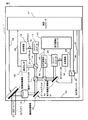
- An acquisition apparatus includes an optical receiver that receives an external beam as a reception beam, a reception beam acquisition unit that performs an acquisition operation for guiding the reception beam to the optical receiver, and a transmission beam for transmission to the outside. And a transmission beam scanning unit that causes the transmission beam to perform a scanning operation, and an optical circulator in which the reception beam is incident and the transmission beam is emitted from the same terminal.
- the acquisition method of the present invention is characterized in that an external beam is acquired as a reception beam, and scanning is performed on a transmission beam for transmission to the outside independently of the acquisition step.
- the acquisition program of the present invention causes a computer to execute an acquisition process for acquiring an external beam as a reception beam, and a scanning process for causing a transmission beam to be transmitted to the outside independently of the acquisition process. It is characterized by that.
- the capturing device, capturing method, and capturing program of the present invention can achieve the effect of completing the capturing operation in a short time without using beacon light based on the simultaneous execution of the scanning operation and the capturing operation.
- the coarse acquisition mechanism unit 11 is controlled by the coarse acquisition control signal 34 from the acquisition controller 31, performs coarse adjustment of the direction of the received beam received from the other party, and guides the received beam after the coarse adjustment to the optical antenna 15.
- the optical antenna 15 narrows the beam diameter of the incident reception beam and sends it to the fine capture mechanism unit 12.
- the fine capture mechanism unit 12 is controlled by the fine capture control signal 35 from the capture controller 31 to perform precise adjustment of the direction of the received beam received from the optical antenna 15, and the received beam after the fine adjustment is applied to the polarization beam splitter 14. Send it out.
- the polarization beam splitter 14 functions as an optical circulator.
- the optical path of the optical circulator may be assumed to have various angles, but in the description of this embodiment, the optical path is sent to the beam splitter 16 without changing the optical axis of the received beam.
- the beam splitter 16 sends a part of the received beam to the capture sensor 32 and sends the rest to the fiber collimator 17.
- the fiber collimator 17 condenses the received beam and guides it to the optical fiber 18.
- the optical fiber 18 sends the collected reception beam to the optical receiver 13.
- the optical receiver 13 extracts received data from the received beam and outputs it to a host device (not shown).
- the capture sensor 32 detects the direction of the incident reception beam by using a built-in optical sensor (not shown) and outputs a capture sensor signal 33 indicating the beam direction to the capture controller 31.
- the optical transmitter 22 receives transmission data from a host device (not shown), etc., generates transmission light based on the transmission data, and sends it to the optical fiber 25.
- the optical fiber 25 guides the received transmission light to the fiber collimator 24.
- the fiber collimator 24 converts the transmission light into a transmission beam (parallel beam) and guides it to the optical difference correction mechanism unit 21.
- the optical difference correction mechanism unit 21 changes the direction of the optical axis of the transmission beam.
- the optical difference correction mechanism unit 21 is controlled by the scanning control signal 36 from the capture controller 31 or the optical difference control signal 44 from the optical difference controller 41, and the transmission beam The direction is changed and guided to the beam splitter 23.
- the beam splitter 23 guides part of the guided transmission beam to the optical difference sensor 42 and guides the rest to the polarization beam splitter 14.
- the optical difference sensor 42 creates an optical difference sensor signal 43 indicating the direction of the transmission beam from the received transmission beam and outputs it to the optical difference controller 41.
- the polarizing beam splitter 14 changes the direction of the optical axis of the incident transmission beam and guides it in the direction of the fine capturing mechanism unit 12.
- the fine capture mechanism unit 12 guides the incident transmission beam to the optical antenna 15, and the optical antenna 15 guides the transmission beam to the coarse capture mechanism unit 11 by expanding its diameter.
- the coarse capture mechanism unit 11 irradiates the counterpart apparatus with the incident transmission beam.
- the capturing device 1 according to the present embodiment configures an optical system capable of performing a transmission beam scanning operation independently of the optical system related to the reception beam. Based on the provision of this configuration, the capturing apparatus 1 according to the present embodiment can simultaneously perform the capturing operation using the reception beam and the scanning operation using the transmission beam.
- the capturing device 1 according to the present embodiment is configured to guide the transmission beam to the fine capturing mechanism unit 12 using the polarization beam splitter 14 that receives the transmission beam from the optical difference correction mechanism unit 21.
- the capturing device 1 according to the present embodiment is configured such that the polarization beam splitter 14 functions as an optical circulator in which the terminal that receives the reception beam and the terminal that emits the transmission beam are the same. Based on such a configuration, the capturing apparatus 1 according to the present embodiment can set the reception beam and the transmission beam to substantially the same optical axis. As will be described later, the optical system related to the reception beam including the coarse acquisition mechanism unit 11 and the fine acquisition mechanism unit 12 is directed toward the counterpart device based on the reception beam during the acquisition operation or the tracking operation. .
- the capture device 1 is configured to irradiate the transmission beam in the direction of the counterpart device based on the configuration in which the coarse capture mechanism unit 11 and the fine capture mechanism unit 12 are used to irradiate the transmission beam. ing.
- the capturing device 1 performs each operation (scanning operation) with respect to the optical axis of the received beam with respect to the optical axis of the received beam in a scanning operation or an optical difference correcting operation using the optical difference correcting mechanism unit 21 described later.
- it is configured to deviate only up to the largest angle of the optical line difference correction operation.
- the acquisition device 1 transmits in parallel with the acquisition operation based on the received beam coming from the direction of the counterpart device even in communication with a device several thousand km away. A scanning operation using a beam can be performed.
- the capture controller 31 controls each part of the capture device 1 based on the capture sensor signal 33 and the like. Specifically, the capture controller 31 uses the coarse capture control signal 34 to move the coarse capture mechanism unit 11, the fine capture control signal 35 uses the fine capture mechanism unit 12, and the scanning control signal 36 uses the optical path difference.
- the correction mechanism unit 21 controls the optical difference switch 26 using the switch control signal 37, respectively.
- the optical difference controller 41 receives the optical difference sensor signal 43 and controls the optical difference correction mechanism unit 21 using the optical difference control signal 44.
- the optical line difference switch 26 is controlled using a switch control signal 37 from the capture controller 31, and either the scanning control signal 36 from the capture controller 31 or the optical line difference control signal 44 from the optical line difference controller 41. As a control signal to the optical difference correction mechanism unit 21.
- the operation of the capturing device 1 according to this embodiment will be described. First, the scanning operation using the transmission beam when the partner performs the capturing operation will be described.
- the capture controller 31 uses the scanning control signal 36 to control the optical difference correction mechanism unit 21 to scan the transmission beam from the optical transmitter 22 and perform a scanning operation.
- the capture controller 31 In order to execute this scanning operation, the capture controller 31 first switches the optical row difference switch 26 using the switch control signal 37, and the scan control signal 36 output from the capture controller 31 is changed to the optical row difference correction mechanism unit 21. Set to input. Thereafter, the capture controller 31 uses the scanning control signal 36 to control the optical line difference correcting mechanism unit 21 so that the predetermined scanning range moves at a predetermined speed and scanning path, and based on this, the optical transmitter that sends the light to the other party. The direction of the transmission beam from 22 is changed, and the scanning operation is performed. Next, the capturing operation performed by the capturing device 1 when the partner is performing a scanning operation will be described.
- the capture controller 31 When starting the capture operation, the capture controller 31 first obtains the direction in which the counterpart device (satellite or the like) is scheduled from a database or the like, and obtains the direction in which the other counterpart device is present at the start of capture. Then, the capture controller 31 uses the coarse capture control signal 34 based on the obtained direction to set the coarse capture mechanism unit 11 to face the direction in which the counterpart device is predicted to exist. (Hereinafter, this operation may be referred to as a program operation.) Next, the capture controller 31 also sets the initial direction of the fine capture mechanism unit 12 using the fine capture control signal 35. The initial direction of the fine capture mechanism unit 12 of this embodiment is set to the center of the movable range in order to ensure the movable range after detecting the other direction.
- the acquisition controller 31 waits for the arrival of a transmission beam transmitted based on the scanning operation of the counterpart apparatus. If the partner apparatus performs a scanning operation within an appropriate range, the capture sensor 32 can detect the transmission beam from the partner apparatus. When receiving the transmission beam, the capture sensor 32 outputs a capture sensor signal 33 indicating the detection direction to the capture controller 31. When the transmission beam cannot be detected even after a predetermined time has elapsed, the capture controller 31 performs a retry operation, for example, by rotating the direction of the coarse capture mechanism unit 11 by a predetermined angle and performing a detection operation again. The acquisition controller 31 determines in which direction the transmission beam is detected based on the received acquisition sensor signal 33.
- the capture controller 31 uses the fine capture control signal 35 to direct the fine capture mechanism unit 12 in the direction from which the transmission beam came.
- the capture controller 31 uses the coarse capture control signal 34 to send the coarse capture mechanism unit 11 to the transmission beam.
- a coarse capture operation directed in the direction may be performed.
- the capture operation performed using the fine capture mechanism unit 12 will be described in more detail with reference to FIG.
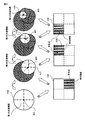
- FIG. 2 is a schematic diagram showing the scanning range of the capturing device 1 and the detection area of the capturing sensor 32 according to the first embodiment of the present invention.
- the upper series of scanning ranges 100 to 103 in FIG. 2 indicate the range in which the transmission beam is scanned.
- the scanning operation is performed substantially concentrically, and the scanning range 100 indicates the scanning range in the first scanning operation and is the entire scannable range (first scanning range).
- the capture controller 31 changes the scanning range. At this time, the scanning range gradually increases as shown in the scanning range 101 to the scanning range 103. It is narrowed (second scanning range to fourth scanning range).
- a series of detection areas 104 to 106 in the lower part of FIG. 2 shows how the capture sensor 32 receives the transmission beam.
- a quadrant sensor is used as the capture sensor 32.
- this is an example, and the present invention is not limited to this.
- the center of the scanning operation of the transmission beam in this embodiment (the center of the substantially concentric scanning) is shifted by the amount of optical row difference as will be described later. Therefore, although the center of the scanning range and the center of the direction of the fine capturing mechanism 12 are strictly shifted by the amount of the optical line difference, the optical line difference itself is small and the drawing becomes complicated. It is the figure which omitted the optical difference. (Note that if the scanning range in FIG. 2 is regarded as the scanning range when it reaches the counterpart device, there is no need to take into account the optical line difference, and the center of the scanning range and the center of the fine capturing mechanism 12 direction are The relationship shown in FIG.
- a scanning operation using the optical row difference correction mechanism unit 21 is performed on the entire scanning range (a circle in the first scanning range of the scanning range 100). Further, the fine capture mechanism unit 12 faces the initial direction, that is, the direction of the center (point A).
- the capture sensor 32 receives the transmission beam transmitted by the scanning operation of the counterpart apparatus during the scanning operation for the first scanning range (detection region 104)
- the scanning range is changed. In the case of this detection region 104, the capture sensor 32 detects the received light at the lower right light receiving unit among the four divided light receiving units, and outputs a capture sensor signal 33 indicating that fact.
- the capture controller 31 that has received the capture sensor signal 33 knows that the capture sensor 32 has received the received beam at the lower right light receiving unit, and the direction in which the counterpart device exists is in the lower right of the light receiving area of the capture sensor 32. It turns out that it is in the range of 1/4. Therefore, the capture controller 31 directs the fine capture mechanism 12 toward the center of the lower right range (point B of the scanning range 101). (Hereinafter, the operation of directing the fine capture mechanism unit 12 in a specific direction may be referred to as a pointing operation.) Further, the capture controller 31 changes the scanning range performed by the optical row difference correction mechanism unit 21 to the lower right (circle of the second scanning range of the scanning range 101), and continues scanning.
- the area of the second scanning range is approximately 1 ⁇ 4 of the area of the first scanning range.
- the capture sensor 32 detects the next light reception (detection region 105).
- the detection direction is the upper right light receiving portion of the capture sensor 32. Since the capture controller 31 detects the beam with the light receiving unit at the upper right of the capture sensor 32, it can be seen that the direction of the other party is at the upper right of the current scanning range. Therefore, the capture controller 31 directs the fine capture mechanism unit 12 in the direction of the upper right (point C of the scan range 102) of the previously narrowed range (second scan range).
- the capture controller 31 changes the scanning range performed by the optical row difference correction mechanism unit 21 so as to be the upper right range (the circle of the third scanning range of the scanning range 102).
- the area of the third scanning range is approximately 1/4 with respect to the second scanning range, and is approximately 1/16 compared to the first scanning range.
- the capture controller 31 repeats this operation until it can be determined that the capture operation has converged.
- the determination that the capturing operation has converged (finished) is made when the size of the scanning range becomes smaller than a predetermined size (for example, the spread angle of the transmission beam). Needless to say, the determination condition is not limited to this, and other determination conditions may be adopted.
- the capture controller 31 may set the termination condition that the movement amount in the pointing operation of the fine capture mechanism unit 12 is shorter than a predetermined length. If the capture controller 31 determines that the capture operation has converged, the capture controller 31 ends the capture operation and proceeds to the tracking operation. Finally, the optical difference correction operation will be described.
- the partner device shifts from the capturing operation to the tracking operation (the description is omitted because it is a well-known technique) and the scanning operation is completed, the capturing controller 31 uses the switch control signal 37 to switch the optical row difference switch 26 to the optical row difference controller 41. Is set on the optical line difference control signal 44 side.
- the optical difference controller 41 that has received the optical difference sensor signal 43 from the optical difference correction sensor 42 determines the direction of the transmission beam obtained from the optical difference sensor signal 43 and the direction for obtaining the necessary optical difference. The difference is obtained, and an optical difference control signal 44 for correcting the difference is generated and sent to the optical difference correction mechanism unit 21. Receiving the optical difference control signal 44, the optical difference correction mechanism unit 21 sets the optical axis direction of the transmission beam so as to face the direction of the optical difference necessary for the transmission beam.
- a required optical difference can be calculated
- FIG. 3 is a state transition diagram summarizing the operation state of the capturing device 1 according to the first embodiment. Details of the state transition of each operation will be described with reference to FIG.
- the coarse capturing mechanism unit 11 is set as a program operation
- the fine capturing mechanism unit 12 is set as a directing operation
- the optical line difference correcting mechanism unit 21 is configured as a scanning operation
- the optical line difference switch 26 is set as a scanning operation side. Yes.
- the capturing device 1 is in a waiting state for receiving a transmission beam corresponding to the scanning operation of the counterpart device using the capturing sensor 32 (step S1000).
- the fine capture mechanism unit 12 changes the directing direction based on the received light of the capture sensor 32 (step S1001), and the light The scanning range of the line difference correction mechanism unit 21 is also changed to a narrowed range (step S1002). Then, the capture controller 31 returns to the next light reception waiting state. Each time light reception by the capture sensor 32 is repeated, the capture controller 31 repeats the same operation, and changes the directivity direction of the fine capture mechanism unit 12 and narrows down the scanning area of the optical row difference correction mechanism unit 21.
- the capture controller 31 performs the tracking operation / optical row difference correction.
- the operation proceeds (step S1003).
- the coarse capture mechanism unit 11 and the fine capture mechanism unit 12 perform the tracking operation
- the light travel difference correction mechanism unit 21 performs the light travel difference correction operation
- the light travel difference switch 26 operates on the light travel difference side. It becomes the setting.
- the scanning operation performed by the optical difference correcting mechanism unit 21 and the capturing operation performed by the fine capturing mechanism unit 12 can be performed in parallel.
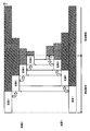
- FIG. 4 is a schematic diagram of the sequence of the scanning operation of the capturing device 1 according to the first embodiment.
- the upper stage is the sequence of the scanning operation of the one-side capture device (device X in FIG. 4), and the lower stage is the counterpart capture device (device Y in FIG. 4).
- the horizontal axis is a time axis.
- the up and down arrows indicate the time when the scanning beam based on the scanning operation of the counterpart device is detected by the capture sensor 32, and as a result, the change of the scanning range has occurred.
- the device X first receives light is described.
- the device Y first receives light the device X and the device Y in the following description may be interchanged.
- the scanning time in each scanning operation is schematically shown.
- the portion without the hatched line indicates the time when the scanning operation is actually performed, and the hatched portion indicates the scanning required when the scanning operation is continued. Shows time.
- the hatched portion indicates the scanning time that is unnecessary because the scanning beam is detected and the scanning range is changed (for example, when the scanning is shifted from scanning 1 to scanning 2).
- each device performs a capturing operation
- the capturing operation is omitted in FIG. 4 for convenience of explanation because each device is integrated with the scanning operation.
- the operation in FIG. 4 proceeds as follows. First, apparatus X receives the scanning beam from apparatus Y. The apparatus X uses the received light to change the scanning range (corresponding to the scanning range 101 from the scanning range 100 in FIG. 2). As a result, the apparatus X can omit the scanning operation corresponding to the hatched portion of the scan 1. Next, the device Y receives the scanning beam from the device X, and similarly shifts from scanning 1 to scanning 2. Subsequently, the device X receives the scanning beam from the device Y and shifts from scanning 2 to scanning 3.
- each device repeats light reception and scanning operation independently in parallel, and when the scanning range becomes narrower than the predetermined range, each device ends the capturing operation and proceeds to the tracking operation.
- the scanning range becomes 1 ⁇ 4 each time light reception is detected.
- the scanning range is narrowed by a geometric series, approximately 1/4, every time the scanning beam is detected.
- the scanning path is a path in which scanning beams overlap, so that the area of the scanning range is substantially proportional to the scanning time. Accordingly, as the scanning range becomes narrower in the geometric series, the scanning time also becomes shorter in the geometric series.
- the ratio of the range to be narrowed is proportional to the range narrowed down using the capture sensor 32. Therefore, when a sensor that is divided more than the four-divided sensor of the present embodiment is used, the capturing apparatus 1 can make the geometric series of the scanning range a geometric series that converges more quickly. As described above, the capturing device 1 according to the first embodiment of the present invention can obtain an effect that the capturing time can be shortened without using beacon light. The reason is that the capturing device 1 uses a configuration that can perform a scanning operation using the optical difference correction mechanism unit 21 while performing the capturing operation by the fine capturing mechanism unit 12, and performs the capturing operation and the scanning operation. It is because it can implement simultaneously.
- the capture device 1 narrows down the directing operation of the fine capture mechanism unit 12 and the scanning range of the optical difference correction mechanism unit 21 based on the direction of the received beam detected in the capture operation. This is because the time required for the capturing operation can be further shortened. If the movable range of the optical difference correcting mechanism unit 21 is narrower than the movable range of the fine capturing mechanism unit 12, the direction directed as a result of the pointing operation performed by the fine capturing mechanism unit 12 is the optical differential. There is a possibility of deviating from the scanning range of the correction mechanism unit 21. In such a case, since the capturing operation cannot be performed, the capturing device 1 needs to retry the capturing operation.
- the movable range of the optical difference correcting mechanism unit 21 is at least the same as or larger than the movable range of the fine capturing mechanism unit 12, an effect of reducing time wasted in the capturing operation can be obtained.
- the reason is that the scanning range of the scanning beam scanned by the optical difference correction mechanism unit 21 by the scanning operation necessarily includes the range of the directing operation performed by the fine capturing mechanism unit 12, so This is because the scanning beam is always within the range even if it faces in the direction. Further, in the present embodiment, it is possible to obtain an effect that the scanning operation and the capturing operation can be performed in parallel even in communication over a long distance such as that used in free space optical communication.
- FIG. 5 is an example of the scanning path of the transmission beam according to the first embodiment.
- the scanning path 201 is scanned outward in a spiral shape from the center with the predicted optical path difference correction direction (optical path difference correction predicted position 203) as the center of the scanning range 200. Is shown.
- the reason why the scanning path in which the transmission beam 202 overlaps in the spiral of FIG. 5 is that the fluctuation of the transmission beam 202 according to the vibration of the capturing device 1 and the like is taken into account, and is overlapped as a margin. Yes.
- the capturing apparatus 1 may employ a spiral from the outer periphery to the center, a raster system that performs linear scanning, or the like, contrary to FIG. However, if the scanning path 201 shown in FIG.
- the direction in which the opponent is most likely to be in the initial state is the predicted optical direction difference correction direction, and there is a high possibility that the opponent is in the vicinity.
- the scanning path starting from the direction of the optical line difference correction and scanning the periphery thereof is a scanning path capable of scanning a place where the partner apparatus is likely to be present.
- the capture controller 31 and the optical difference controller 41 are described as separate components for convenience of explanation, but may be configured as a single controller.
- the capturing apparatus 1 may configure each block and operation content of FIG. 1 such as the optical difference switch 26 as a computer program.
- the capturing device 1 may be configured by three or more controllers in which the coarse capturing mechanism unit 11 and the fine capturing mechanism unit 12 are separate controllers. Subsequently, a simulation result of the first embodiment will be described.
- the capture operation using the two devices X and Y shown in FIG. 4 was simulated.
- the capture range was ⁇ 0.2 °
- the light diameter of the transmission beam was 20 ⁇ rad
- the margin with respect to the light diameter of the transmission beam was 20%
- the capture sensor 32 was a quadrant sensor.
- the detection band was 2 kHz
- scanning was a spiral from the center.
- the apparatus X and the apparatus Y have the same conditions.
- the results of the simulation of the three cases in this embodiment are shown below.
- the first case is a case where the counterpart device always receives light at the end of the scanning operation, and is the worst case that takes the most time for the capturing operation.
- the first scanning operation takes about 95 seconds
- the second scanning operation takes about 48 seconds
- the third scanning operation takes about 12 seconds
- the capturing operation takes about 159 seconds.
- the second case is a case where the counterpart device is present in the capture range with an equal probability, and is a case where the direction of the counterpart device is distributed on average.
- the first scanning operation takes about 47 seconds
- the second scanning operation takes about 22 seconds
- the third scanning operation takes about 6 seconds
- the acquisition operation is completed. It was about 78 seconds.
- the third case is a case in which the counterpart device is distributed along a normal distribution (Gaussian distribution) that averages the center of the capture range, and is close to the actual operation of the device.
- the first scanning operation takes about 24 seconds
- the second scanning operation takes about 12 seconds
- the third scanning operation takes about 3 seconds
- the acquisition operation is completed. It was about 40 seconds.
- the capture time in the case of alternately performing the scanning operation and the capture operation as shown in FIG.
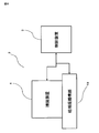
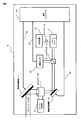
- FIG. 10 is a block diagram showing the overall configuration of the acquisition system 2 according to the second embodiment of the present invention.
- the capturing system 2 of the present embodiment includes a control device 3 that controls the whole, a capturing device 4 that performs a fine capturing operation and a scanning operation, and a coarse capturing mechanism unit 19 that is controlled by the control device 3 and performs a rough capturing operation. It is configured to include.
- the control device 3 performs the same control as each controller of the first embodiment.
- the coarse capturing mechanism unit 19 performs a program operation according to an instruction to the control device 3, and performs a coarse capturing operation and a coarse tracking operation that change the direction of the capturing device 4 mounted on the coarse capturing mechanism unit 19.
- the coarse capturing mechanism 19 can be configured by using a general-purpose biaxial rotary table device, a gimbal device, or the like, and thus detailed description thereof is omitted.
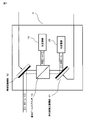
- FIG. 7 is a block diagram showing a configuration of the capturing device 4 of the present embodiment.
- the capturing device 4 in FIG. 7 includes a fine capturing mechanism unit 12, an optical receiver 13, a polarization beam splitter 14, an optical row difference correcting mechanism unit 21, and an optical transmitter 22.
- a rough capturing operation using a program operation is performed using the control device 3 and the rough capturing mechanism unit 19. Therefore, as the capturing device 4, the directing operation and fine tracking operation performed by the fine capturing mechanism unit 12 and the optical receiver 13, the scanning operation performed by the optical line difference correcting mechanism unit 21 and the optical transmitter 22, and the optical operation are performed. Perform the difference correction operation.
- the capture device 4 can also obtain substantially the same optical axis of the reception beam and the transmission beam by using the polarization beam splitter 14 as an optical circulator. Using such a configuration, the capture device 4 used for long-distance optical communication can obtain the effect of speeding up the capture operation without using beacon light. The reason is that it includes a fine capturing mechanism unit 12 and an optical receiver 13 that perform a capturing operation, an optical row difference correcting mechanism unit 21 and an optical transmitter 22 that perform a scanning operation, and the capturing operation and the scanning operation are performed simultaneously in parallel. This is because it can be executed.
- the polarization beam splitter 14 can be used to obtain substantially the same optical axis of the transmission beam and the reception beam.
- the capturing device 4 can obtain an effect of speeding up the rough capturing operation performed by the rough capturing mechanism unit 19. The reason is that since the control device 3 is configured as a separate device from the capturing device 4, the device that the coarse capturing mechanism 19 moves is the capturing device 4. (Third embodiment) In the first embodiment, the scanning operation using the optical difference correction mechanism unit 21 has been described. However, the scanning operation only needs to be able to scan the transmission beam, and the scanning operation can be realized using other configurations.
- FIG. 11 is a block diagram showing a configuration of the capturing device 6 according to the third embodiment of the present invention.
- the capturing device 6 according to the third embodiment performs a scanning operation using the coarse capturing mechanism unit 11 in addition to the optical row difference correcting mechanism unit 21. Therefore, the capturing device 6 includes a scanning controller 61 and a coarse capturing switch 62, and the capturing operation 1 according to the first embodiment is realized by using these configurations and the capturing controller 63 and the like. And different.
- the capture controller 63 performs the same operation as that of the capture controller 31 according to the first embodiment. Further, the capture controller 63 controls the scanning operation performed by the scanning controller 61 using the scanning controller control signal 64, and receives scanning operation information 65 indicating the state of the scanning operation from the scanning controller 61. The capture controller 63 also controls the coarse capture switch 62 using the coarse capture switch control signal 66.
- the capture controller 63 corresponds to the optical line corresponding to the scanning signal 36 according to the first embodiment. There is no need to output a signal for controlling the difference correction mechanism 21.
- the scanning controller 61 receives the scanning controller control signal 64 from the capture controller 63 and controls the scanning operation. Specifically, the scan controller 61 uses the coarse scan control signal 67 to scan the coarse capture mechanism 11 (hereinafter referred to as the coarse scan operation) and the fine scan control signal 68 to use the optical line difference.
- the scanning operation of the correction mechanism unit 21 (hereinafter referred to as a fine scanning operation) is controlled.
- the scanning controller 61 sends scanning operation information 65 representing the state of the scanning operation to the capture controller 63. Similar to the optical difference switch 26 of the capturing apparatus 1 according to the first embodiment, the optical difference switch 26 is controlled by the acquisition controller 63 and sends a control signal to the optical difference correction mechanism unit 21.
- the optical row difference switch 26 has the same control signal input as that of the optical row difference switch 26 according to the first embodiment, except that a fine scanning control signal 68 used for the scanning operation is received from the scanning controller 61. Different from the first embodiment.
- the optical difference correction mechanism unit 21 performs the same optical difference correction operation as the optical difference correction mechanism unit 21 according to the first embodiment on the basis of the control signal received from the optical difference switch 26, and will be described in detail later. The fine scanning operation is performed.
- the coarse capture switch 62 is controlled based on the coarse capture switch control signal 66 from the capture controller 63, and either the coarse scan control signal 67 from the scan controller 61 or the coarse capture control signal 34 from the capture controller 63 is selected. It is sent out to the coarse capturing mechanism 11.
- the coarse acquisition mechanism unit 11 receives the coarse acquisition control signal 34 from the coarse acquisition switch 62, the coarse acquisition mechanism unit 11 performs an acquisition operation similar to the coarse acquisition mechanism unit 11 according to the first embodiment, and receives the coarse scanning control signal 67. If this is the case, a coarse scanning operation, which will be described in detail later, is performed. Next, the scanning operation of the capturing device 6 according to the third embodiment will be described.
- the capture controller 63 uses the coarse capture switch control signal 66 so that the coarse capture control signal 67 output from the scan controller 61 is input to the coarse capture mechanism unit 11. 62 is set. Further, the capture controller 63 uses the switch control signal 37 to set the optical line difference switch 26 so that the fine scanning control signal 68 output from the scanning controller 61 is input to the optical line difference correcting mechanism unit 21. After setting each switch, the capture controller 63 performs control including a start instruction and an end instruction of the scanning operation performed by the scan controller 61 using the scan controller control signal 64.
- the scan controller 61 that has received an instruction using the scan controller control signal 64 uses the coarse scan control signal 67 to perform the rough capture mechanism unit 11, and uses the fine scan control signal 68 to perform the optical row difference correction mechanism unit 21. And a scanning operation using the transmission beam from the optical transmitter 22 is performed.
- the capturing device 6 according to the third embodiment uses two mechanisms, and can perform two types of scanning operations, a rough scanning operation and a fine scanning operation. Note that the capturing device 6 according to the third embodiment also performs the capturing operation while performing the scanning operation, similarly to the capturing device 1 according to the first embodiment. However, in the capturing device 6, a coarse scanning operation using the rough capturing mechanism unit 11 is performed.
- the capturing controller 63 receives the scanning operation information 65 indicating the state of the scanning operation from the scanning controller 61, and the coarse scanning operation for the directing operation of the fine capturing mechanism unit 12 using the fine capturing control signal 35. Control so as not to be affected by. As this control, for example, the capture controller 63 performs a directing operation in a direction in which the capture operation is stopped during the coarse scan operation or a direction corrected by the coarse scan operation is corrected after the coarse scan operation is completed. The capture operation is controlled as is done.
- a transmission beam scanning path according to the third embodiment will be described with reference to FIG. FIG.
- the scanning path shown in FIG. 12 is an example of a scanning path of a transmission beam according to the third embodiment.
- the scanning path shown in FIG. 12 has the optical line difference correction direction (optical line difference correction predicted position 203) predicted by the counterpart apparatus obtained from the database or the like described in the first embodiment as the center of the scanning range.
- An example of a scanning path that scans outward in a substantially spiral shape from the center is shown. However, the scanning path may start the scanning operation from a place different from the center of the scanning range.
- the scanning path of FIG. 12 divides the scanning range 210 into a plurality of regions (hereinafter referred to as clusters 214).
- the scan controller 61 uses a coarse scan operation using the coarse capture mechanism unit 11 to move the transmission beam 212 between the clusters 214, and performs a fine scan using the optical row difference correction mechanism unit 21 for the scan operation in the cluster 214.
- Use behavior However, the configuration for realizing the coarse scanning operation and the fine scanning operation is divided for convenience of explanation, and the function is divided between the coarse capturing mechanism unit 11 and the optical row difference correcting mechanism unit 21. Of course, the coarse scanning operation and the fine scanning operation may be performed in cooperation.
- the scanning controller 61 directs the transmission beam 212 toward the center of the center cluster, that is, the prediction direction of the optical row difference correction, based on the coarse scanning operation using the coarse capturing mechanism unit 11, and the coarse capturing mechanism unit 11 Fix in the direction.
- the scanning controller 61 performs a fine scanning operation (scanning path 215) in a spiral shape from the center of the cluster to the outside by using the optical row difference correction mechanism unit 21.
- the scanning controller 61 performs the scanning operation for the cluster adjacent to the outside of the central cluster. Therefore, the scanning controller 61 performs a coarse scanning operation (scanning path 216) using the coarse capturing mechanism unit 11, moves the transmission beam from the central cluster to the adjacent cluster, and the coarse capturing mechanism unit in the central direction of the cluster. 11 is fixed.
- the scanning controller 61 performs a fine scanning operation (scanning path 215) spirally from the center to the outside using the optical row difference correction mechanism unit 21 in the same manner as the central cluster.
- the scanning controller 61 When the scanning operation for the cluster is completed, the scanning controller 61 performs the scanning operation for the next cluster adjacent to the central cluster. When the scanning operation for the cluster adjacent to the central cluster is completed, the scanning controller 61 performs the scanning operation for the outer cluster. As described above, the scan controller 61 repeats the coarse scan operation for moving the cluster from the central cluster to the outer cluster in a substantially spiral shape and the fine scan operation in the cluster to perform the scan operation. Note that displacement in the scanning direction may occur due to relative movement between the own apparatus and the counterpart apparatus during the scanning operation. Therefore, in the capturing device 6 according to the third embodiment, the scanning controller 61 receives information regarding this displacement, and performs correction in the scanning operation.
- the scanning controller 61 does not necessarily need to be configured to receive information from the capture controller 63.
- the scan controller 61 may receive the capture sensor signal 33 of the capture sensor 32 directly.
- the scanning controller 61 that has received the information on the displacement performs a fine scanning operation in which the displacement of the relative position between the apparatuses using the optical row difference correcting mechanism unit 21 is corrected. Further, in the next coarse scan operation, the scan controller 61 fixes the coarse capture mechanism unit 11 in a direction that takes into account the correction performed by the optical difference correction mechanism unit 21 with respect to the center of the cluster after movement.
- the optical row difference correcting mechanism unit 21 can perform the fine scanning operation on the center whose displacement is corrected.
- the capturing device 6 according to the third embodiment can perform a scanning operation corresponding to the displacement based on the relative movement between the devices.
- the scanning path of the transmission beam does not necessarily have to be the path illustrated in FIG.
- the capturing device 6 may employ a spiral from the outer periphery to the center, a raster method for linear scanning, or the like, contrary to the path of FIG.
- the capturing device 6 may have different shapes for the coarse scanning operation path and the fine scanning operation path.
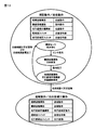
- FIG. 13 is a state transition diagram summarizing the operation states of the capturing device 6 according to the third embodiment.
- the column of the coarse capture switch 62 is added to each table, the operation of the coarse capture mechanism unit 11 during the capture operation / scan operation is a scan operation, and the change of the scan range is coarse.
- the point where the capture mechanism 11 is added is different from the state transition diagram (FIG. 3) according to the first embodiment. This is because in the capturing device 6 according to the third embodiment, the coarse capturing mechanism unit 11 performs the coarse scanning operation.
- the capture controller 63, the scan controller 61, and the optical difference controller 41 are described as separate components for convenience of explanation, but two or all of them are described. May be configured as one controller.
- the scanning controller 61 outputs the fine scanning control signal 68 for controlling the optical difference correction mechanism unit 21 to control the scanning operation centrally. Because. Therefore, as long as information can be exchanged between the controllers, the scanning controller 61 does not necessarily have to control both the fine scanning operation and the rough scanning operation.
- the capture controller 63 may send out the control signal for the fine scanning operation in the same manner as the capture device 1 according to the first embodiment.
- the capturing device 6 may be composed of four or more controllers in which the fine scanning control signal 68 is controlled by another controller. When several controllers are combined, the capturing device 6 is configured as a computer program (not shown) including the operation contents of each block and switch in FIG. 11 such as the optical difference switch 26 and the coarse capturing switch 62. May be. Further, in the capturing device 6 according to the third embodiment, the description is given of the operation that combines the fine scanning operation using the optical row difference correcting mechanism unit 21 and the coarse scanning operation using the coarse capturing mechanism unit 11. However, it is not always necessary to perform both scanning operations, and only one of the scanning operations may be performed.
- the capturing device 6 first performs a fine scanning operation around the current direction. Then, when the counterpart apparatus cannot be detected only by the fine scanning operation, the capturing device 6 may perform a scanning operation that combines the coarse scanning operation and the fine capturing operation.
- the capturing device 6 according to the third embodiment configured as described above has a movable range in a scanning operation using the optical difference correction mechanism unit 21 in addition to the effect of the capturing device 1 according to the first embodiment. The effect which can be narrowed can be acquired.
- the reason for this is that, for a large scanning operation in the scanning range, a rough scanning operation using the rough capturing mechanism unit 11 is performed, so that the optical row difference correcting mechanism unit 21 realizes a scanning operation within the range of each cluster. This is because it is good.
- the capturing device 6 according to the third embodiment can obtain an effect of realizing a scanning operation corresponding to the displacement between devices during the scanning operation. The reason is that the displacement in the scanning direction caused by the relative movement with the counterpart device during the scanning operation is corrected using the fine scanning operation using the optical row difference correction mechanism unit 21, and the correction is considered in the next coarse operation. This is because the coarse capturing mechanism 11 is fixed in the direction.
- the capturing device 6 according to the third embodiment can obtain an effect of realizing the coarse scanning operation without changing the rough capturing mechanism unit 11.
- the reason is that the optical scanning difference correction mechanism unit 21 performs the fine scanning operation, and the coarse capturing mechanism unit 11 is fixed in the center direction of each cluster in the scanning operation. This is because a new high-precision angle detector or the like is unnecessary.
Abstract
There have been problems that a capturing device requires a light source having a large power output, and a scanning operation and a capturing operation must be alternately performed by the respective devices.
A capturing device is provided with a light receiver which receives a beam from outside as a reception beam, a reception beam capturing unit which performs a capturing operation by which the reception beam is introduced to the light receiver, a light transmitter which generates a transmission beam transmitted to the outside, a transmission beam scanning unit which performs a scanning operation using the transmission beams, and an optical circulator wherein the incidence of the reception beam and the exit of the transmission beam are performed at the same terminal.
Description
本発明は、捕捉装置、捕捉方法、及び、捕捉プログラムに関し、特に、光通信における通信ビームの捕捉装置、捕捉方法、及び、捕捉プログラムに関する。
The present invention relates to a capturing device, a capturing method, and a capturing program, and more particularly to a communication beam capturing device, a capturing method, and a capturing program in optical communication.
光を使用した通信として、光ファイバを使用した光ファイバ通信が知られている。光ファイバ通信は、低損失の光ファイバと半導体レーザとを使用し、長距離通信網として発展している。しかし、光ファイバ通信では、光ファイバの損失、及び、波長分散などのため、通信距離が100km程度までに制限されている。
このような光ファイバに対し、自由空間、特に宇宙空間は、光の吸収・散乱・分散などの少ない良質な通信路となる。この自由空間を通信路として使用した光通信技術は、地球周回軌道上の人工衛星相互間での通信、或は、人工衛星と地上局との間の通信など、数千kmから数万kmの距離での通信を実現することが出来る。
自由空間を通信路として使用する通信には、光通信のほかに、マイクロ波を使用したマイクロ波通信がある。ところで、通信に使用される光やマイクロ波などの電磁波のビームの広がり角は、使用される電磁波の波長に比例する。光の波長は、数百nmであり、衛星通信に使用されるマイクロ波の波長(1mm~0.1m)の数千分の1から数十万分の1程度と非常に短い。このため、マイクロ波通信に対し、光通信では、使用するビームを狭く絞り込むことができ、相手装置に到達した通信ビームのエネルギー密度も高くなり、エネルギー効率のよい通信システムを構築することができる。
このように、光通信は、エネルギー効率のよい通信システムを構築できるが、ビームの広がり角が狭いため、高い精度のビーム方向の合わせ込みが必要となる。
さらに、光通信では、通信距離が長いため、振動などに基づく通信装置のわずかな位置や角度の変動を原因として、通信先でのビームが大きく変位し、例え地球静止軌道上の人工衛星同士であっても、ビームの方向を固定したままでは、長距離の光通信を維持することが難しい。
そのため、光通信の捕捉装置は、通信相手の方向の変化や自装置の変位に応じて相手を追尾するための追尾機構を備えて、通信を維持している。
また、静止衛星と地球周回軌道上を移動する人工衛星との通信、地球周回衛星同士の通信、あるいは地球周回衛星と地上局との通信などでは、通信相手が、通信可能範囲に現れたり外れたりするため、通信相手を見つけ出す捕捉動作も必要となる。
このため、自由空間を使用した光通信の捕捉装置は、通信相手を見つけだすための捕捉動作を行う捕捉機構と、移動していく相手に追従する追尾機構とを備えている。
特に、人工衛星と地上局との通信などでは、180°近い半天範囲の移動と、1°未満の数千km先の装置への方向合わせといった、異なる二つの要求に対応することが必要となる。このような要求を1つの機構で実現することは、難しい。そこで、一般的に用いられている光通信の捕捉装置では、可動範囲が大きいが動作速度が遅い粗捕捉機構部と可動範囲は狭いが応答速度が速い精捕捉機構部とを備えて実現している。(例えば特許文献1および2参照。)
ところで、捕捉装置は、通信相手の方向を、相手からの受光ビームを使用して求める。また、捕捉装置は、その受光ビームから求めた相手の方向を基に、自装置からの送信ビームを送り出している。しかし、光通信は通信距離が長いため、たとえ高速の光ビームを使用していても、相手がビームを出射してから、こちらのビームが相手に届くまでの間に、相手の位置が変化してしまう。そのため、送信ビームの送り出す方向は、受信ビームから求めた相手方向を基に相手の位置変化を考慮した補正が必要となる。この受信ビームと送信ビームとの方向の差の角度を光行差と呼び、送信ビームの光行差を補正するために、光行差補正機構を備えた光通信の捕捉装置が用いられている。(例えば特許文献3参照。)
このような構成を備えた通信装置の捕捉装置は、通信を行うために、最初に相手の方向を見つけ出す捕捉動作を行う。
衛星の軌道上の大まかな方向などは、ある程度前もって予測することは出来る。しかし、通常の通信に使用されるビームの広がり角は狭いため、ビームの広がり角程度の精度で通信相手の方向を予想することは難しい。そのため、相手方向を見つけ出す捕捉動作が行われている。
この捕捉動作として、例えば、通信ビームに比べ、出力パワーが大きく広がり角も大きいビーコン光を利用した捕捉動作を行うものがある。(例えば特許文献4参照。)
図8に一般的に用いられるビーコン光を用いた捕捉装置の一例を示す。
捕捉される側の捕捉装置8は、ビーコン光学系51から広がり角が広いビーコン光を照射する。ここにおけるビーコン光は、捕捉する相手側がいると予測される角度範囲を含む広がり角を備えている。また、ビーコン光は、通常の通信に使用されるビームなどに比べ、かなり広い広がり角で照射される必要があり、且つ、そのビーコン光が相手に届いたときに所定のエネルギー密度を確保するため、高出力の光学系が必要となる。ビーコン光学系51から出力されたビーコン光は、相手装置(図示せず)に照射されるが、その際、光アンテナ52および粗捕捉機構部11を用いて相手装置に向けて十分な広がり角を保ったビーコン光として照射される。
捕捉動作を行う側の捕捉装置8の捕捉コントローラ53は、まず、粗捕捉制御信号34を用いて粗捕捉機構部11を相手の予測方向に合わせる。一方、捕捉コントローラ53は、精捕捉制御信号35を用いて精捕捉機構部12を初期方向に向くように設定する。この状態で、捕捉コントローラ53は、相手装置からのビーコン光を待つ。相手装置からのビーコン光は、粗捕捉機構部11、光アンテナ52、精捕捉機構部12およびビームスプリッタ16を介して、捕捉センサ32で受光される。十分な広がり角と強度とをもつビーコン光であれば、そのようなビーコン光を常に捕捉センサ32で受光することが出来る。捕捉センサ32は、受光したビーコン光の方向を示す捕捉センサ信号33を捕捉コントローラ53に出力する。捕捉コントローラ53は、捕捉センサ信号33からの精捕捉制御信号35を使用して、ビーコン光の中心が捕捉センサ32の中心となるように、精捕捉機構部12の向きを制御する。なお、捕捉コントローラ53は、必要に応じて粗捕捉制御信号34を用いて粗捕捉機構部11を動作させることが可能である。
これに対し、捕捉コントローラ31は、送信ビームを走査させて捕捉動作を行うこともできる。
なお、送信側の装置の送信ビームは、受信側の装置においては受信ビームとなる。以下の説明では便宜上、煩雑さを避けるため、どちらも走査ビームと言う場合もある。
図9に一般的に用いられる走査ビームを使用した走査動作の一例を示す。
この例の場合、片方の装置(図9の装置X)は、可動範囲全体を、走査ビームを用いて走査し、その走査ビームを相手側の装置(図9の装置Y)で検出して捕捉動作が行われる。装置Yが行う捕捉動作は、必ずしも1回の装置Xの走査動作で終了となるわけではない。そのため、装置Xの走査動作は、複数回繰り返すことが必要となる。
装置Yの捕捉動作が終わった段階で、今度は装置Yが走査ビームを使用した走査動作を行い、装置Xが捕捉動作を行う。なお、この段階では装置Yの捕捉動作が終わっているため、装置Yからの走査ビームは、必ず装置Xに到達する。そのため、装置Xが行う捕捉動作は、装置Yの捕捉動作に比べ短い時間で終了する。
しかし、このような捕捉装置では、狭い走査ビームを用いて走査範囲全体を複数回走査することが必要となるため、走査動作に長い時間が必要となり、その結果、相手装置での捕捉時間も長くなる。
そこで、捕捉時間を短縮するため、図10に示すような、走査動作と捕捉動作とを双方の装置で交互に行う方式を採用した捕捉装置が用いられる。
図10に示す捕捉装置における捕捉方法では、まず、片方の装置(図10の装置X)が、走査ビームの走査動作(走査1)を行う。その走査動作に対して、相手側装置(図10の装置Y)が、捕捉動作を行う。装置Yは、この捕捉動作に基づいて自装置(装置Y)における走査範囲をある程度絞り込むことができる。装置Yは、その絞り込んだ範囲での走査動作(走査2)を行う。
装置Xは、装置Yが行う走査2に対して捕捉動作を行い、捕捉動作が終わると、今度は装置Xが、同様に装置Yに対して走査範囲を絞り込んだ走査2を行う。装置Yは、装置Xが行う走査2に対する捕捉動作を行う。装置Yは、走査2を用いて、走査1より正確な相手方向の検出ができ、さらに走査範囲を絞り込むことも出来る。
このように走査範囲を絞り込みながら、相互に相手装置の方向を絞り込んでいくため、図9を参照して説明した捕捉装置における捕捉動作に比べ、図10を参照して説明した捕捉装置は、捕捉時間の短縮した捕捉動作を実現している。
なお、このような捕捉装置では、送信ビームと受信ビームとのズレを少なくするため、光軸を共軸とすることも行われている。(例えば、特許文献5を参照。)
特許第2518066号公報(特開平03−152490)
特開2001−203641号公報
特開平07−307703号公報
特開平10−233738号公報
特開平02−180311号公報
As communication using light, optical fiber communication using an optical fiber is known. Optical fiber communication is developed as a long-distance communication network using a low-loss optical fiber and a semiconductor laser. However, in optical fiber communication, the communication distance is limited to about 100 km due to optical fiber loss and chromatic dispersion.
In contrast to such an optical fiber, free space, particularly outer space, is a high-quality communication path with little light absorption / scattering / dispersion. Optical communication technology using this free space as a communication path is a communication between satellites on earth orbit, or communication between artificial satellites and ground stations. Communication at a distance can be realized.
Communication using free space as a communication channel includes microwave communication using microwaves in addition to optical communication. By the way, the divergence angle of an electromagnetic wave such as light or microwave used for communication is proportional to the wavelength of the electromagnetic wave used. The wavelength of light is several hundred nanometers, which is very short, from one thousandth to several hundred thousandths of the microwave wavelength (1 mm to 0.1 m) used for satellite communication. For this reason, in optical communication, compared to microwave communication, the beam to be used can be narrowed down, the energy density of the communication beam reaching the counterpart device is increased, and an energy efficient communication system can be constructed.
As described above, optical communication can construct an energy efficient communication system. However, since the beam divergence angle is narrow, alignment of the beam direction with high accuracy is required.
Furthermore, in optical communication, the communication distance is long, so the beam at the communication destination is greatly displaced due to slight fluctuations in the position and angle of the communication device based on vibrations, etc. Even so, it is difficult to maintain long-distance optical communication if the beam direction is fixed.
For this reason, an optical communication capturing device is provided with a tracking mechanism for tracking a partner in accordance with a change in the direction of the communication partner or a displacement of the own device, and maintains communication.
Also, in communications between geostationary satellites and artificial satellites moving in orbit around the earth, communications between earth-orbiting satellites, or communications between earth-orbiting satellites and ground stations, the communication partner appears or falls within the communicable range. Therefore, a capturing operation for finding a communication partner is also required.
For this reason, an optical communication capturing device using a free space includes a capturing mechanism that performs a capturing operation for finding a communication partner and a tracking mechanism that tracks a moving partner.
In particular, in communication between an artificial satellite and a ground station, it is necessary to cope with two different demands such as movement in a half sky range of nearly 180 ° and direction adjustment to a device that is several thousand kilometers less than 1 °. . It is difficult to realize such a request with one mechanism. Therefore, a generally used optical communication capture device is provided with a coarse capture mechanism with a large movable range but a slow operation speed and a fine capture mechanism with a narrow movable range but a fast response speed. Yes. (For example, refer toPatent Documents 1 and 2.)
By the way, the capturing device obtains the direction of the communication partner by using the received light beam from the partner. Further, the capturing device sends out a transmission beam from its own device based on the direction of the other party obtained from the received light beam. However, because optical communication has a long communication distance, even if a high-speed light beam is used, the position of the other party changes after the other party emits the beam until this beam reaches the other party. End up. Therefore, the direction in which the transmission beam is transmitted needs to be corrected in consideration of the position change of the other party based on the other party direction obtained from the received beam. The angle of the difference between the directions of the reception beam and the transmission beam is called an optical difference, and an optical communication capturing device including an optical difference correction mechanism is used to correct the optical difference of the transmission beam. . (For example, refer toPatent Document 3.)
In order to perform communication, the capturing device of the communication device having such a configuration first performs a capturing operation for finding the direction of the other party.
The general direction of the satellite in the orbit can be predicted to some extent in advance. However, since the divergence angle of the beam used for normal communication is narrow, it is difficult to predict the direction of the communication partner with the accuracy of the beam divergence angle. For this reason, a capturing operation for finding the other party's direction is performed.
As this capturing operation, for example, there is one that performs a capturing operation using beacon light having a larger output power and a larger spread angle than a communication beam. (For example, refer toPatent Document 4.)
FIG. 8 shows an example of a capturing device using beacon light that is generally used.
The capturing device 8 on the side to be captured emits beacon light having a wide divergence angle from the beaconoptical system 51. The beacon light here has a divergence angle including an angle range in which it is predicted that there is a partner to be captured. Also, the beacon light needs to be irradiated with a considerably wide divergence angle compared to a beam used for normal communication, and in order to ensure a predetermined energy density when the beacon light reaches the other party. A high output optical system is required. The beacon light output from the beacon optical system 51 is irradiated to a partner device (not shown). At this time, a sufficient divergence angle is directed toward the partner device using the optical antenna 52 and the coarse capturing mechanism unit 11. Irradiated as kept beacon light.
Thecapture controller 53 of the capture device 8 that performs the capture operation first uses the coarse capture control signal 34 to align the coarse capture mechanism unit 11 with the predicted direction of the other party. On the other hand, the capture controller 53 uses the fine capture control signal 35 to set the fine capture mechanism unit 12 to face the initial direction. In this state, the capture controller 53 waits for a beacon light from the counterpart device. The beacon light from the partner device is received by the capture sensor 32 via the coarse capture mechanism unit 11, the optical antenna 52, the fine capture mechanism unit 12, and the beam splitter 16. If the beacon light has a sufficient spread angle and intensity, such a beacon light can always be received by the capture sensor 32. The capture sensor 32 outputs a capture sensor signal 33 indicating the direction of the received beacon light to the capture controller 53. The capture controller 53 uses the fine capture control signal 35 from the capture sensor signal 33 to control the orientation of the fine capture mechanism unit 12 so that the center of the beacon light becomes the center of the capture sensor 32. The capture controller 53 can operate the coarse capture mechanism unit 11 using the coarse capture control signal 34 as necessary.
On the other hand, theacquisition controller 31 can perform the acquisition operation by scanning the transmission beam.
Note that the transmission beam of the transmission-side apparatus becomes a reception beam in the reception-side apparatus. In the following description, for the sake of convenience, both may be referred to as scanning beams for the sake of convenience.
FIG. 9 shows an example of a scanning operation using a scanning beam generally used.
In this example, one device (device X in FIG. 9) scans the entire movable range using a scanning beam, and the scanning beam is detected and captured by the other device (device Y in FIG. 9). Operation is performed. The capturing operation performed by the device Y does not necessarily end with a single scanning operation of the device X. Therefore, the scanning operation of the apparatus X needs to be repeated a plurality of times.
At the stage where the capturing operation of the device Y is completed, the device Y performs a scanning operation using the scanning beam, and the device X performs the capturing operation. At this stage, since the capturing operation of the apparatus Y is finished, the scanning beam from the apparatus Y always reaches the apparatus X. Therefore, the capturing operation performed by the device X is completed in a shorter time than the capturing operation of the device Y.
However, in such a capturing device, it is necessary to scan the entire scanning range a plurality of times using a narrow scanning beam, so that a long time is required for the scanning operation, and as a result, the capturing time in the counterpart device is also long. Become.
Therefore, in order to shorten the capture time, a capture device that employs a method in which the scanning operation and the capture operation are alternately performed by both devices as shown in FIG. 10 is used.
In the capturing method in the capturing device shown in FIG. 10, first, one device (device X in FIG. 10) performs a scanning beam scanning operation (scan 1). In response to the scanning operation, the counterpart device (device Y in FIG. 10) performs a capturing operation. The apparatus Y can narrow down the scanning range in the own apparatus (apparatus Y) to some extent based on this capturing operation. The apparatus Y performs a scanning operation (scan 2) within the narrowed range.
The apparatus X performs the capturing operation on thescan 2 performed by the apparatus Y, and when the capturing operation ends, the apparatus X performs the scan 2 that similarly narrows the scanning range with respect to the apparatus Y. The device Y performs a capturing operation for the scan 2 performed by the device X. The apparatus Y can detect the opposite direction more accurately than the scan 1 using the scan 2, and can further narrow the scan range.
In this way, the direction of the counterpart device is narrowed down while narrowing down the scanning range, so that the capture device described with reference to FIG. 10 captures in comparison with the capture operation in the capture device described with reference to FIG. The capture operation is shortened.
In such a capturing device, the optical axis is also set as a coaxial axis in order to reduce the deviation between the transmission beam and the reception beam. (For example, see Patent Document 5)
Japanese Patent No. 2518066 (Japanese Patent Laid-Open No. 03-152490) JP 2001-203641 A Japanese Patent Application Laid-Open No. 07-307703 Japanese Patent Laid-Open No. 10-233738 Japanese Patent Laid-Open No. 02-180311
このような光ファイバに対し、自由空間、特に宇宙空間は、光の吸収・散乱・分散などの少ない良質な通信路となる。この自由空間を通信路として使用した光通信技術は、地球周回軌道上の人工衛星相互間での通信、或は、人工衛星と地上局との間の通信など、数千kmから数万kmの距離での通信を実現することが出来る。
自由空間を通信路として使用する通信には、光通信のほかに、マイクロ波を使用したマイクロ波通信がある。ところで、通信に使用される光やマイクロ波などの電磁波のビームの広がり角は、使用される電磁波の波長に比例する。光の波長は、数百nmであり、衛星通信に使用されるマイクロ波の波長(1mm~0.1m)の数千分の1から数十万分の1程度と非常に短い。このため、マイクロ波通信に対し、光通信では、使用するビームを狭く絞り込むことができ、相手装置に到達した通信ビームのエネルギー密度も高くなり、エネルギー効率のよい通信システムを構築することができる。
このように、光通信は、エネルギー効率のよい通信システムを構築できるが、ビームの広がり角が狭いため、高い精度のビーム方向の合わせ込みが必要となる。
さらに、光通信では、通信距離が長いため、振動などに基づく通信装置のわずかな位置や角度の変動を原因として、通信先でのビームが大きく変位し、例え地球静止軌道上の人工衛星同士であっても、ビームの方向を固定したままでは、長距離の光通信を維持することが難しい。
そのため、光通信の捕捉装置は、通信相手の方向の変化や自装置の変位に応じて相手を追尾するための追尾機構を備えて、通信を維持している。
また、静止衛星と地球周回軌道上を移動する人工衛星との通信、地球周回衛星同士の通信、あるいは地球周回衛星と地上局との通信などでは、通信相手が、通信可能範囲に現れたり外れたりするため、通信相手を見つけ出す捕捉動作も必要となる。
このため、自由空間を使用した光通信の捕捉装置は、通信相手を見つけだすための捕捉動作を行う捕捉機構と、移動していく相手に追従する追尾機構とを備えている。
特に、人工衛星と地上局との通信などでは、180°近い半天範囲の移動と、1°未満の数千km先の装置への方向合わせといった、異なる二つの要求に対応することが必要となる。このような要求を1つの機構で実現することは、難しい。そこで、一般的に用いられている光通信の捕捉装置では、可動範囲が大きいが動作速度が遅い粗捕捉機構部と可動範囲は狭いが応答速度が速い精捕捉機構部とを備えて実現している。(例えば特許文献1および2参照。)
ところで、捕捉装置は、通信相手の方向を、相手からの受光ビームを使用して求める。また、捕捉装置は、その受光ビームから求めた相手の方向を基に、自装置からの送信ビームを送り出している。しかし、光通信は通信距離が長いため、たとえ高速の光ビームを使用していても、相手がビームを出射してから、こちらのビームが相手に届くまでの間に、相手の位置が変化してしまう。そのため、送信ビームの送り出す方向は、受信ビームから求めた相手方向を基に相手の位置変化を考慮した補正が必要となる。この受信ビームと送信ビームとの方向の差の角度を光行差と呼び、送信ビームの光行差を補正するために、光行差補正機構を備えた光通信の捕捉装置が用いられている。(例えば特許文献3参照。)
このような構成を備えた通信装置の捕捉装置は、通信を行うために、最初に相手の方向を見つけ出す捕捉動作を行う。
衛星の軌道上の大まかな方向などは、ある程度前もって予測することは出来る。しかし、通常の通信に使用されるビームの広がり角は狭いため、ビームの広がり角程度の精度で通信相手の方向を予想することは難しい。そのため、相手方向を見つけ出す捕捉動作が行われている。
この捕捉動作として、例えば、通信ビームに比べ、出力パワーが大きく広がり角も大きいビーコン光を利用した捕捉動作を行うものがある。(例えば特許文献4参照。)
図8に一般的に用いられるビーコン光を用いた捕捉装置の一例を示す。
捕捉される側の捕捉装置8は、ビーコン光学系51から広がり角が広いビーコン光を照射する。ここにおけるビーコン光は、捕捉する相手側がいると予測される角度範囲を含む広がり角を備えている。また、ビーコン光は、通常の通信に使用されるビームなどに比べ、かなり広い広がり角で照射される必要があり、且つ、そのビーコン光が相手に届いたときに所定のエネルギー密度を確保するため、高出力の光学系が必要となる。ビーコン光学系51から出力されたビーコン光は、相手装置(図示せず)に照射されるが、その際、光アンテナ52および粗捕捉機構部11を用いて相手装置に向けて十分な広がり角を保ったビーコン光として照射される。
捕捉動作を行う側の捕捉装置8の捕捉コントローラ53は、まず、粗捕捉制御信号34を用いて粗捕捉機構部11を相手の予測方向に合わせる。一方、捕捉コントローラ53は、精捕捉制御信号35を用いて精捕捉機構部12を初期方向に向くように設定する。この状態で、捕捉コントローラ53は、相手装置からのビーコン光を待つ。相手装置からのビーコン光は、粗捕捉機構部11、光アンテナ52、精捕捉機構部12およびビームスプリッタ16を介して、捕捉センサ32で受光される。十分な広がり角と強度とをもつビーコン光であれば、そのようなビーコン光を常に捕捉センサ32で受光することが出来る。捕捉センサ32は、受光したビーコン光の方向を示す捕捉センサ信号33を捕捉コントローラ53に出力する。捕捉コントローラ53は、捕捉センサ信号33からの精捕捉制御信号35を使用して、ビーコン光の中心が捕捉センサ32の中心となるように、精捕捉機構部12の向きを制御する。なお、捕捉コントローラ53は、必要に応じて粗捕捉制御信号34を用いて粗捕捉機構部11を動作させることが可能である。
これに対し、捕捉コントローラ31は、送信ビームを走査させて捕捉動作を行うこともできる。
なお、送信側の装置の送信ビームは、受信側の装置においては受信ビームとなる。以下の説明では便宜上、煩雑さを避けるため、どちらも走査ビームと言う場合もある。
図9に一般的に用いられる走査ビームを使用した走査動作の一例を示す。
この例の場合、片方の装置(図9の装置X)は、可動範囲全体を、走査ビームを用いて走査し、その走査ビームを相手側の装置(図9の装置Y)で検出して捕捉動作が行われる。装置Yが行う捕捉動作は、必ずしも1回の装置Xの走査動作で終了となるわけではない。そのため、装置Xの走査動作は、複数回繰り返すことが必要となる。
装置Yの捕捉動作が終わった段階で、今度は装置Yが走査ビームを使用した走査動作を行い、装置Xが捕捉動作を行う。なお、この段階では装置Yの捕捉動作が終わっているため、装置Yからの走査ビームは、必ず装置Xに到達する。そのため、装置Xが行う捕捉動作は、装置Yの捕捉動作に比べ短い時間で終了する。
しかし、このような捕捉装置では、狭い走査ビームを用いて走査範囲全体を複数回走査することが必要となるため、走査動作に長い時間が必要となり、その結果、相手装置での捕捉時間も長くなる。
そこで、捕捉時間を短縮するため、図10に示すような、走査動作と捕捉動作とを双方の装置で交互に行う方式を採用した捕捉装置が用いられる。
図10に示す捕捉装置における捕捉方法では、まず、片方の装置(図10の装置X)が、走査ビームの走査動作(走査1)を行う。その走査動作に対して、相手側装置(図10の装置Y)が、捕捉動作を行う。装置Yは、この捕捉動作に基づいて自装置(装置Y)における走査範囲をある程度絞り込むことができる。装置Yは、その絞り込んだ範囲での走査動作(走査2)を行う。
装置Xは、装置Yが行う走査2に対して捕捉動作を行い、捕捉動作が終わると、今度は装置Xが、同様に装置Yに対して走査範囲を絞り込んだ走査2を行う。装置Yは、装置Xが行う走査2に対する捕捉動作を行う。装置Yは、走査2を用いて、走査1より正確な相手方向の検出ができ、さらに走査範囲を絞り込むことも出来る。
このように走査範囲を絞り込みながら、相互に相手装置の方向を絞り込んでいくため、図9を参照して説明した捕捉装置における捕捉動作に比べ、図10を参照して説明した捕捉装置は、捕捉時間の短縮した捕捉動作を実現している。
なお、このような捕捉装置では、送信ビームと受信ビームとのズレを少なくするため、光軸を共軸とすることも行われている。(例えば、特許文献5を参照。)
In contrast to such an optical fiber, free space, particularly outer space, is a high-quality communication path with little light absorption / scattering / dispersion. Optical communication technology using this free space as a communication path is a communication between satellites on earth orbit, or communication between artificial satellites and ground stations. Communication at a distance can be realized.
Communication using free space as a communication channel includes microwave communication using microwaves in addition to optical communication. By the way, the divergence angle of an electromagnetic wave such as light or microwave used for communication is proportional to the wavelength of the electromagnetic wave used. The wavelength of light is several hundred nanometers, which is very short, from one thousandth to several hundred thousandths of the microwave wavelength (1 mm to 0.1 m) used for satellite communication. For this reason, in optical communication, compared to microwave communication, the beam to be used can be narrowed down, the energy density of the communication beam reaching the counterpart device is increased, and an energy efficient communication system can be constructed.
As described above, optical communication can construct an energy efficient communication system. However, since the beam divergence angle is narrow, alignment of the beam direction with high accuracy is required.
Furthermore, in optical communication, the communication distance is long, so the beam at the communication destination is greatly displaced due to slight fluctuations in the position and angle of the communication device based on vibrations, etc. Even so, it is difficult to maintain long-distance optical communication if the beam direction is fixed.
For this reason, an optical communication capturing device is provided with a tracking mechanism for tracking a partner in accordance with a change in the direction of the communication partner or a displacement of the own device, and maintains communication.
Also, in communications between geostationary satellites and artificial satellites moving in orbit around the earth, communications between earth-orbiting satellites, or communications between earth-orbiting satellites and ground stations, the communication partner appears or falls within the communicable range. Therefore, a capturing operation for finding a communication partner is also required.
For this reason, an optical communication capturing device using a free space includes a capturing mechanism that performs a capturing operation for finding a communication partner and a tracking mechanism that tracks a moving partner.
In particular, in communication between an artificial satellite and a ground station, it is necessary to cope with two different demands such as movement in a half sky range of nearly 180 ° and direction adjustment to a device that is several thousand kilometers less than 1 °. . It is difficult to realize such a request with one mechanism. Therefore, a generally used optical communication capture device is provided with a coarse capture mechanism with a large movable range but a slow operation speed and a fine capture mechanism with a narrow movable range but a fast response speed. Yes. (For example, refer to
By the way, the capturing device obtains the direction of the communication partner by using the received light beam from the partner. Further, the capturing device sends out a transmission beam from its own device based on the direction of the other party obtained from the received light beam. However, because optical communication has a long communication distance, even if a high-speed light beam is used, the position of the other party changes after the other party emits the beam until this beam reaches the other party. End up. Therefore, the direction in which the transmission beam is transmitted needs to be corrected in consideration of the position change of the other party based on the other party direction obtained from the received beam. The angle of the difference between the directions of the reception beam and the transmission beam is called an optical difference, and an optical communication capturing device including an optical difference correction mechanism is used to correct the optical difference of the transmission beam. . (For example, refer to
In order to perform communication, the capturing device of the communication device having such a configuration first performs a capturing operation for finding the direction of the other party.
The general direction of the satellite in the orbit can be predicted to some extent in advance. However, since the divergence angle of the beam used for normal communication is narrow, it is difficult to predict the direction of the communication partner with the accuracy of the beam divergence angle. For this reason, a capturing operation for finding the other party's direction is performed.
As this capturing operation, for example, there is one that performs a capturing operation using beacon light having a larger output power and a larger spread angle than a communication beam. (For example, refer to
FIG. 8 shows an example of a capturing device using beacon light that is generally used.
The capturing device 8 on the side to be captured emits beacon light having a wide divergence angle from the beacon
The
On the other hand, the
Note that the transmission beam of the transmission-side apparatus becomes a reception beam in the reception-side apparatus. In the following description, for the sake of convenience, both may be referred to as scanning beams for the sake of convenience.
FIG. 9 shows an example of a scanning operation using a scanning beam generally used.
In this example, one device (device X in FIG. 9) scans the entire movable range using a scanning beam, and the scanning beam is detected and captured by the other device (device Y in FIG. 9). Operation is performed. The capturing operation performed by the device Y does not necessarily end with a single scanning operation of the device X. Therefore, the scanning operation of the apparatus X needs to be repeated a plurality of times.
At the stage where the capturing operation of the device Y is completed, the device Y performs a scanning operation using the scanning beam, and the device X performs the capturing operation. At this stage, since the capturing operation of the apparatus Y is finished, the scanning beam from the apparatus Y always reaches the apparatus X. Therefore, the capturing operation performed by the device X is completed in a shorter time than the capturing operation of the device Y.
However, in such a capturing device, it is necessary to scan the entire scanning range a plurality of times using a narrow scanning beam, so that a long time is required for the scanning operation, and as a result, the capturing time in the counterpart device is also long. Become.
Therefore, in order to shorten the capture time, a capture device that employs a method in which the scanning operation and the capture operation are alternately performed by both devices as shown in FIG. 10 is used.
In the capturing method in the capturing device shown in FIG. 10, first, one device (device X in FIG. 10) performs a scanning beam scanning operation (scan 1). In response to the scanning operation, the counterpart device (device Y in FIG. 10) performs a capturing operation. The apparatus Y can narrow down the scanning range in the own apparatus (apparatus Y) to some extent based on this capturing operation. The apparatus Y performs a scanning operation (scan 2) within the narrowed range.
The apparatus X performs the capturing operation on the
In this way, the direction of the counterpart device is narrowed down while narrowing down the scanning range, so that the capture device described with reference to FIG. 10 captures in comparison with the capture operation in the capture device described with reference to FIG. The capture operation is shortened.
In such a capturing device, the optical axis is also set as a coaxial axis in order to reduce the deviation between the transmission beam and the reception beam. (For example, see Patent Document 5)
しかし、上述した特許文献4の捕捉動作にビーコン光を用いる捕捉装置では、ビーコン光用として大出力の光源が必要となるという問題があった。
また、図10に示した捕捉装置では、それぞれの装置が、走査動作と捕捉動作とを交互に行わなければならないという問題があった。
本発明の目的は、上述の問題を解決し、捕捉動作の時間を短くすることができる捕捉装置、捕捉方式、及び、捕捉プログラムを提供することにある。 However, the above-described capturing device using beacon light for the capturing operation ofPatent Document 4 has a problem that a high-output light source is required for beacon light.
Further, the capturing device shown in FIG. 10 has a problem that each device must alternately perform a scanning operation and a capturing operation.
An object of the present invention is to provide a capturing device, a capturing method, and a capturing program that can solve the above-described problems and can shorten the time of capturing operation.
また、図10に示した捕捉装置では、それぞれの装置が、走査動作と捕捉動作とを交互に行わなければならないという問題があった。
本発明の目的は、上述の問題を解決し、捕捉動作の時間を短くすることができる捕捉装置、捕捉方式、及び、捕捉プログラムを提供することにある。 However, the above-described capturing device using beacon light for the capturing operation of
Further, the capturing device shown in FIG. 10 has a problem that each device must alternately perform a scanning operation and a capturing operation.
An object of the present invention is to provide a capturing device, a capturing method, and a capturing program that can solve the above-described problems and can shorten the time of capturing operation.
本発明の捕捉装置は、外部からのビームを受信ビームとして受信する光受信器と、前記受信ビームを前記光受信器に導く捕捉動作を行う受信ビーム捕捉部と、外部に送信するための送信ビームを生成する光送信器と、前記送信ビームに走査動作を行わせる送信ビーム走査部と、前記受信ビームの入射と前記送信ビームの出射が同一端子である光サーキュレータとを備えることを特徴とする。
本発明の捕捉方法は、外部からのビームを受信ビームとして捕捉し、前記捕捉ステップとは独立して外部に送信するための送信ビームに走査することを含むことを特徴とする。
本発明の捕捉プログラムは、外部からのビームを受信ビームとして捕捉する捕捉処理と、前記捕捉処理とは独立に外部に送信するための送信ビームに走査動作を行わせる走査処理とをコンピュータに実行させることを特徴とする。 An acquisition apparatus according to the present invention includes an optical receiver that receives an external beam as a reception beam, a reception beam acquisition unit that performs an acquisition operation for guiding the reception beam to the optical receiver, and a transmission beam for transmission to the outside. And a transmission beam scanning unit that causes the transmission beam to perform a scanning operation, and an optical circulator in which the reception beam is incident and the transmission beam is emitted from the same terminal.
The acquisition method of the present invention is characterized in that an external beam is acquired as a reception beam, and scanning is performed on a transmission beam for transmission to the outside independently of the acquisition step.
The acquisition program of the present invention causes a computer to execute an acquisition process for acquiring an external beam as a reception beam, and a scanning process for causing a transmission beam to be transmitted to the outside independently of the acquisition process. It is characterized by that.
本発明の捕捉装置、捕捉方式、及び、捕捉プログラムは、走査動作と捕捉動作とを同時に実行することに基づき、ビーコン光を使用せずに、短時間に捕捉動作を完了できる効果が得られる。
The capturing device, capturing method, and capturing program of the present invention can achieve the effect of completing the capturing operation in a short time without using beacon light based on the simultaneous execution of the scanning operation and the capturing operation.
1 捕捉装置
2 捕捉システム
3 制御装置
4 捕捉装置
6 捕捉装置
8 捕捉装置
11 粗捕捉機構部
12 精捕捉機構部
13 光受信器
14 偏光ビームスプリッタ
15 光アンテナ
16 ビームスプリッタ
17 ファイバコリメータ
18 光ファイバ
19 粗捕捉機構部
21 光行差補正機構部
22 光送信器
23 ビームスプリッタ
24 ファイバコリメータ
25 光ファイバ
26 光行差スイッチ
31 捕捉コントローラ
32 捕捉センサ
33 捕捉センサ信号
34 粗捕捉制御信号
35 精捕捉制御信号
36 走査制御信号
37 スイッチ制御信号
41 光行差コントローラ
42 光行差センサ
43 光行差センサ信号
44 光行差制御信号
51 ビーコン光学系
52 光アンテナ
53 捕捉コントローラ
61 走査コントローラ
62 粗捕捉スイッチ
63 捕捉コントローラ
64 走査コントローラ制御信号
65 走査動作情報
66 粗捕捉スイッチ制御信号
67 粗走査制御信号
68 精走査制御信号 DESCRIPTION OF SYMBOLS 1Capture apparatus 2 Capture system 3 Control apparatus 4 Capture apparatus 6 Capture apparatus 8 Capture apparatus 11 Coarse capture mechanism part 12 Fine capture mechanism part 13 Optical receiver 14 Polarization beam splitter 15 Optical antenna 16 Beam splitter 17 Fiber collimator 18 Optical fiber 19 Coarse Capture mechanism unit 21 Optical difference correction mechanism unit 22 Optical transmitter 23 Beam splitter 24 Fiber collimator 25 Optical fiber 26 Optical difference switch 31 Capture controller 32 Capture sensor 33 Capture sensor signal 34 Coarse capture control signal 35 Fine capture control signal 36 Scanning Control signal 37 Switch control signal 41 Optical difference controller 42 Optical difference sensor 43 Optical difference sensor signal 44 Optical difference control signal 51 Beacon optical system 52 Optical antenna 53 Acquisition controller 61 Scanning controller 62 Coarse acquisition switch 6 Acquisition controller 64 scan controller control signal 65 scanning operation information 66 coarse acquisition switch control signal 67 coarse scan control signal 68 fine scan control signal
2 捕捉システム
3 制御装置
4 捕捉装置
6 捕捉装置
8 捕捉装置
11 粗捕捉機構部
12 精捕捉機構部
13 光受信器
14 偏光ビームスプリッタ
15 光アンテナ
16 ビームスプリッタ
17 ファイバコリメータ
18 光ファイバ
19 粗捕捉機構部
21 光行差補正機構部
22 光送信器
23 ビームスプリッタ
24 ファイバコリメータ
25 光ファイバ
26 光行差スイッチ
31 捕捉コントローラ
32 捕捉センサ
33 捕捉センサ信号
34 粗捕捉制御信号
35 精捕捉制御信号
36 走査制御信号
37 スイッチ制御信号
41 光行差コントローラ
42 光行差センサ
43 光行差センサ信号
44 光行差制御信号
51 ビーコン光学系
52 光アンテナ
53 捕捉コントローラ
61 走査コントローラ
62 粗捕捉スイッチ
63 捕捉コントローラ
64 走査コントローラ制御信号
65 走査動作情報
66 粗捕捉スイッチ制御信号
67 粗走査制御信号
68 精走査制御信号 DESCRIPTION OF SYMBOLS 1
次に本発明の実施の形態について図面を参照して詳細に説明する。
最初に、本発明の第1の実施形態の構成および動作について図1~5を参照して説明する。
まず、図1を参照して、本発明の第1の実施形態に係る捕捉装置1の構成について説明する。
相手装置から受け取る受信ビームに関係する構成について説明する。
粗捕捉機構部11は、捕捉コントローラ31からの粗捕捉制御信号34に制御されて、相手から受け取った受信ビームの方向の粗調整を行い、粗調整後の受信ビームを光アンテナ15に導く。
光アンテナ15は、入射した受信ビームのビーム径を絞り、精捕捉機構部12に送る。精捕捉機構部12は、捕捉コントローラ31からの精捕捉制御信号35に制御されて、光アンテナ15から受けた受信ビームの方向の精密調整を行い、精密調整後の受信ビームを偏光ビームスプリッタ14に送り出す。
偏光ビームスプリッタ14は、光サーキュレータとして働く。光サーキュレータの光路としては、いろいろな角度のものが想定されうるが、本実施形態の説明では、受信ビームの光軸を変更せずにビームスプリッタ16に送る光路としている。
ビームスプリッタ16は、受信ビームの一部を捕捉センサ32に送り、残りをファイバコリメータ17に送り出す。
ファイバコリメータ17は、受信ビームを集光して光ファイバ18に導く。光ファイバ18は、集光された受信ビームを光受信器13に送る。光受信器13は、受け取った受信ビームから受信データを取り出し、図示しない上位装置などに出力する。
捕捉センサ32は、図示しない内蔵する光センサなどを用いて、入射した受信ビームの方向を検出し、ビームの方向を示す捕捉センサ信号33を捕捉コントローラ31に出力する。
次に相手装置に送り出す送信ビームに関係する構成について説明する。
光送信器22は、図示しない上位装置などから送信データを受け取り、その送信データを基に送信光を発生し、光ファイバ25に送り出す。光ファイバ25は、受け取った送信光をファイバコリメータ24に導く。ファイバコリメータ24は、送信光を送信ビーム(平行ビーム)に変換して、光行差補正機構部21に導く。
光行差補正機構部21は、送信ビームの光軸の方向を変更するものである。詳細な動作は後述するが、光行差補正機構部21は、捕捉コントローラ31からの走査制御信号36、又は、光行差コントローラ41からの光行差制御信号44に制御されて、送信ビームの方向を変更し、ビームスプリッタ23に導く。
ビームスプリッタ23は、導かれた送信ビームの一部を光行差センサ42に導き、残りを偏光ビームスプリッタ14に導く。
光行差センサ42は、受け取った送信ビームから、送信ビームの方向を示す光行差センサ信号43を作成し、光行差コントローラ41に出力する。
偏光ビームスプリッタ14は、入射した送信ビームを、その光軸の向きを変更して精捕捉機構部12の方向に導く。
精捕捉機構部12は、入射した送信ビームを光アンテナ15に導き、光アンテナ15は、送信ビームを、その径を拡大して粗捕捉機構部11に導く。粗捕捉機構部11は、入射した送信ビームを相手装置に照射する。
このような構成に基づき、本実施形態に係る捕捉装置1は、受信ビームに係る光学系とは独立に、送信ビームの走査動作を行うことができる光学系を構成している。この構成を備えることに基づき、本実施形態に係る捕捉装置1は、受信ビームを用いた捕捉動作と送信ビームを用いた走査動作とを同時並行に行うことができる。
さらに、本実施形態に係る捕捉装置1は、光行差補正機構部21からの送信ビームを受ける偏光ビームスプリッタ14を用いて、送信ビームを精捕捉機構部12に導く構成となっている。つまり、本実施形態に係る捕捉装置1は、偏光ビームスプリッタ14が、受信ビームを入射する端子と送信ビームを出射する端子とを同一とする光サーキュレータとして働くように構成されている。このような構成とすることに基づき、本実施形態に係る捕捉装置1は、受信ビームと送信ビームとを略同一光軸とすることができる。
後述するように、捕捉動作中や追尾動作中などにおいて、粗捕捉機構部11及び精捕捉機構部12を含む受信ビームに関係する光学系は、受信ビームを基に相手装置の方向を向いている。そのため、本実施形態に係る捕捉装置1は、粗捕捉機構部11及び精捕捉機構部12を使用して送信ビームを照射するとの構成に基づき、送信ビームも相手装置の方向に照射する構成となっている。つまり、捕捉装置1は、後述する光行差補正機構部21を用いた走査動作や光行差補正動作において、送信ビームの光軸が、受信ビームの光軸に対して、各動作(走査動作または光行差補正動作)の最も大きくなる角度までしかずれない構成となっている。(以下、走査動作の最大角を最大走査角と言う。)
このような構成に基づき、本実施形態に係る捕捉装置1は、数千kmも離れた装置との通信においても、相手装置の方向から来る受信ビームを基にした捕捉動作と同時並行に、送信ビームを用いた走査動作を行うことが出来る。
最後に、コントローラ関係の構成について説明する。
捕捉コントローラ31は、捕捉センサ信号33などを基に、捕捉装置1の各部を制御する。具体的には、捕捉コントローラ31は、粗捕捉制御信号34を用いて粗捕捉機構部11を、精捕捉制御信号35を用いて精捕捉機構部12を、走査制御信号36を用いて光行差補正機構部21を、スイッチ制御信号37を用いて光行差スイッチ26をそれぞれ制御している。
光行差コントローラ41は、光行差センサ信号43を受け取り、光行差制御信号44を用いて光行差補正機構部21を制御する。
光行差スイッチ26は、捕捉コントローラ31からのスイッチ制御信号37を用いて制御され、捕捉コントローラ31からの走査制御信号36と、光行差コントローラ41からの光行差制御信号44とのどちらかを、光行差補正機構部21に制御信号として送り出す。
次に、本実施形態に係る捕捉装置1の動作について説明する。
まず、相手が捕捉動作を行う場合における、送信ビームを使用した走査動作から説明する。
捕捉コントローラ31は、走査制御信号36を使用して、光行差補正機構部21を制御し、光送信器22からの送信ビームを走査させ、走査動作を行う。この走査動作を実行するため、捕捉コントローラ31は、まず、スイッチ制御信号37を用いて、光行差スイッチ26を切替えて、捕捉コントローラ31が出力する走査制御信号36が光行差補正機構部21に入力するように設定する。その後、捕捉コントローラ31は、走査制御信号36を用いて、光行差補正機構部21が所定の走査範囲を予め決まった速度及び走査経路で動くように制御し、それに基づき相手に送り出す光送信器22からの送信ビームの方向を変更して、走査動作を行う。
続いて、相手が走査動作を行っている場合の、捕捉装置1が行う捕捉動作について説明する。
捕捉コントローラ31は、捕捉動作を開始する場合、まず、相手装置(衛星等)の存在する予定の方向などをデータベースなどから得て、捕捉開始時の大体の相手装置の存在する方向を求める。そして、捕捉コントローラ31は、その求めた方向を基に粗捕捉制御信号34を使用して、粗捕捉機構部11を相手装置が存在すると予測される方向を向くように設定する。(以下、この動作をプログラム動作と言うこともある。)
次に、捕捉コントローラ31は、精捕捉制御信号35を使用して、精捕捉機構部12の初期方向も設定する。本実施形態の精捕捉機構部12の初期方向は、相手方向を検出後の可動範囲の確保などのため、可動範囲の中央を設定している。
その後、捕捉コントローラ31は、相手装置の走査動作に基づいて送信された送信ビームが到着するのを待つ。相手装置が適切な範囲で走査動作を行えば、捕捉センサ32は、相手装置からの送信ビームを検出することができる。捕捉センサ32は、送信ビームを受光すると、その検出方向を示す捕捉センサ信号33を捕捉コントローラ31に出力する。
なお、所定の時間が経過しても送信ビームを検出できない場合、捕捉コントローラ31は、粗捕捉機構部11の方向を所定の角度だけ回転させて再度検出動作を行うなど、リトライ動作を行う。
捕捉コントローラ31は、受け取った捕捉センサ信号33を基に、送信ビームがどの方向で検出されたかを判別する。その結果に基づき、捕捉コントローラ31は、精捕捉制御信号35を使用して、精捕捉機構部12を送信ビームの来た方向に向ける。
なお、捕捉センサ信号33で検出したセンサの検出位置がかなり偏っていた場合など必要に応じて、捕捉コントローラ31は、粗捕捉制御信号34を使用して粗捕捉機構部11を送信ビームの来た方向に向ける粗捕捉動作を行なってもよい。
精捕捉機構部12を用いて行われる捕捉動作について、図2を参照してより詳細に説明する。
図2は、本発明の第1の実施形態に係る捕捉装置1の走査範囲と捕捉センサ32の検出領域とを示す模式図である。図2の上段一連の走査範囲100~103は、送信ビームを走査させる範囲を示している。
後述するように走査動作は略同心円状に行われ、走査範囲100は、最初の走査動作における走査範囲を示し、走査可能範囲全体となっている(第1の走査範囲)。後ほど詳細に説明するように、相手装置の存在する方向が解ると、捕捉コントローラ31は、走査範囲を変更するが、その際、走査範囲は、走査範囲101~走査範囲103に示すように徐々に狭められていく(第2の走査範囲~第4の走査範囲)。
図2の下段の一連の検出領域104~検出領域106は、捕捉センサ32における送信ビームの受光の様子を示す。本実施形態では、捕捉センサ32として四分割センサを使用しているが、これは一例であり、勿論これに限られるものではない。
なお、本実施形態における送信ビームの走査動作の中心(略同心円状走査の中心)は、後述のように光行差の分だけずれている。そのため、走査範囲の中心と精捕捉機構部12の方向の中心とは、厳密には光行差の分だけずれるが、光行差自体が小さく、また、図も煩雑となるため、図2は光行差を省略した図となっている。(なお、図2の走査範囲を相手装置に届いたときの走査範囲と看做すと、光行差を考慮する必要が無くなり、走査範囲の中心と精捕捉機構部12の方向の中心とは、図2に示した関係となる。)
まず、光行差補正機構部21を使用した走査動作が、走査範囲全体(走査範囲100の第1の走査範囲の円)に対して行われる。また、精捕捉機構部12は、初期方向つまり中央(点A)の方向を向いている。
第1の走査範囲に対する走査動作中に捕捉センサ32が相手装置の走査動作で送信した送信ビームを受光する(検出領域104)と走査範囲の変更が発生する。この検出領域104の場合、捕捉センサ32は、4分割された受光部のうちの右下の受光部で受光を検出しているので、その旨を示す捕捉センサ信号33を出力する。
捕捉センサ信号33を受けた捕捉コントローラ31は、捕捉センサ32が右下の受光部で受信ビームを受けたことを知り、相手装置の存在する方向が捕捉センサ32の受光可能領域のうちの右下の1/4の範囲に入っていることが分る。そこで、捕捉コントローラ31は、精捕捉機構部12の方向を右下の範囲の中央(走査範囲101の点B)に向ける。(以下、精捕捉機構部12を特定方向に向ける動作を指向動作と言うこともある。)
さらに、捕捉コントローラ31は光行差補正機構部21が行う走査範囲も右下(走査範囲101の第2の走査範囲の円)となるように変更し、走査を継続する。本実施形態では、第2の走査範囲の面積は、第1の走査範囲の面積の略1/4としている。
第2の走査範囲を走査中に、捕捉センサ32が、次の受光を検出する(検出領域105)。ここでは、検出方向が、捕捉センサ32の右上の受光部である例を示している。
捕捉コントローラ31は、捕捉センサ32の右上の受光部でビームを検出したことから、相手の方向が現在の走査範囲の右上にあることが分る。そこで、捕捉コントローラ31は、先に絞り込んだ範囲(第2の走査範囲)の右上の中心(走査範囲102の点C)方向に精捕捉機構部12を向ける。また、同様に、捕捉コントローラ31は、光行差補正機構部21が行う走査範囲も右上の範囲(走査範囲102の第3の走査範囲の円)となるように変更する。
第3の走査範囲の面積は、第2の走査範囲に対して略1/4であり、第1の走査範囲に比べると略1/16となっている。
捕捉コントローラ31は、この動作を、捕捉動作が収束したと判断できるまで繰り返す。本実施形態では、捕捉動作が収束(終了)したとの判断は、走査範囲の大きさが所定の大きさ(例えば、送信ビームの広がり角)より小さくなったときになされる。
なお、判断条件は、これに限定されるものではなく、他の判断条件を採用してもよいことは言うまでもない。例えば、捕捉コントローラ31は、精捕捉機構部12の指向動作での移動量が所定の長さより短くなったことを終了の条件としてもよい。
捕捉コントローラ31は、捕捉動作が収束したと判断した場合、捕捉動作を終了し、追尾動作に移行する。
最後に、光行差補正動作について説明する。
相手装置が捕捉動作から追尾動作(周知技術のため説明は省略)に移行し走査動作が完了すると、捕捉コントローラ31は、スイッチ制御信号37を用いて、光行差スイッチ26を光行差コントローラ41からの光行差制御信号44側に設定する。光行差補正センサ42から光行差センサ信号43を受けた光行差コントローラ41は、光行差センサ信号43から求めた送信ビームの方向と、必要な光行差を得るための方向との差を求め、その差を補正する光行差制御信号44を作成し、光行差補正機構部21に送る。光行差制御信号44を受けた、光行差補正機構部21は、送信ビームに必要な光行差となる方向を向くように送信ビームの光軸方向を設定する。
なお、必要な光行差は、例えば、粗捕捉機構部11が使用している既に述べたデータベースなどを基に、相手装置との距離及び相手装置の移動速度などから、求めることが出来る。
このような構成に基づき光行差補正動作を行うことが出来る。
図3は、第1の実施形態に係る捕捉装置1の動作状態をまとめた状態遷移図である。
図3を参照して、各動作の状態遷移の詳細について説明する。
捕捉動作/走査動作では、粗捕捉機構部11がプログラム動作、精捕捉機構部12が指向動作、光行差補正機構部21が走査動作、光行差スイッチ26が走査動作側の設定となっている。
最初、捕捉装置1は、捕捉センサ32を使用した相手装置の走査動作に対応した送信ビームの受光待ち状態にある(ステップS1000)。
捕捉センサ32が相手装置からの送信ビームを受光すると、捕捉コントローラ31に指示に基づき、精捕捉機構部12は、受光した捕捉センサ32の受光を基に指向方向を変更し(ステップS1001)、光行差補正機構部21の走査範囲も絞り込んだ範囲に変更となる(ステップS1002)。そして、捕捉コントローラ31は、次の受光待ち状態に戻る。
捕捉センサ32の受光が繰り返されるたびに、捕捉コントローラ31は、同様の動作を繰り返し、精捕捉機構部12の指向方向の変更と光行差補正機構部21の走査領域の絞り込みとを行う。その結果、光行差補正機構部21が行う走査動作の走査範囲が所定の範囲より狭くなり、走査動作を行わなくてもよくなった段階で、捕捉コントローラ31は、追尾動作/光行差補正動作に移行する(ステップS1003)。
追尾動作/光行差補正動作では、粗捕捉機構部11と精捕捉機構部12とが追尾動作、光行差補正機構部21が光行差補正動作、光行差スイッチ26が光行差側の設定となる。
このように、本実施形態の捕捉装置1では、光行差補正機構部21が行う走査動作と、精捕捉機構部12が行う捕捉動作とを同時並行して行うことができる。そして、相手からの受信ビームの受光検出に基づき、精捕捉機構部12の指向方向の変更と、光行差補正機構部21が行う走査動作の走査範囲の変更とが行われる。この結果、捕捉動作の時間を短くすることが出来る。この走査動作と捕捉動作とについて、図4を参照して、さらに詳細に説明する。
図4は、第1の実施形態に係る捕捉装置1の走査動作のシーケンスの模式図である。
上段が片側の捕捉装置(図4の装置X)、下段が相手側の捕捉装置(図4の装置Y)の走査動作のシーケンスとなっている。
なお、図4において、横軸は時間軸となっている。上下の矢印は、相手装置の走査動作に基づく走査ビームを捕捉センサ32で検出した時点を示し、その結果として走査範囲の変更が起きたことを示している。本説明では、最初に装置Xが受光した場合について説明しているが、装置Yが最初に受光した場合には、以下の説明での装置Xと装置Yとを相互に読み替えればよい。
また、各走査動作における走査時間は、模式的に示されており、斜線が無い部分が実際に走査動作を行った時間を示し、斜線部はその走査動作を継続した場合に必要となった走査時間を示している。斜線部分は、走査ビームを検出し、走査範囲を変更(例えば走査1から走査2に移行する場合)したため、不必要となった走査時間を表している。
また、各装置とも捕捉動作を行っているが、それぞれ走査動作と一体となっているため、図4では、説明の便宜のため、捕捉動作を省略した。
図4での動作は、次のように進んでいく。
まず装置Xが、装置Yからの走査ビームを受光する。受光を用いて装置Xは、走査範囲を変更(図2の走査範囲100から走査範囲101に相当)する。その結果、装置Xは、走査1の斜線部分に対応する走査動作を省略できる。次に、装置Yが、装置Xからの走査ビームを受光し、同様に走査1から走査2に移行している。
続いて、装置Xが、装置Yからの走査ビームを受光し、走査2から走査3に移行する。このように、それぞれの装置が、並行独立に受光と走査動作の移行とを繰り返し、走査範囲が所定範囲より狭くなったら、それぞれの装置が捕捉動作を終了し、追尾動作に移行する。
本実施形態では、既に述べたように、走査範囲が受光の検出ごとに1/4となる。つまり、本実施形態では、走査ビームの検出ごとに走査範囲がほぼ1/4と、等比級数的に狭くなっていく。
本実施形態では、後述のように、走査経路として、走査ビームが重なった経路としているため、走査範囲の面積が走査時間とほぼ比例している。従って、走査範囲が等比級数的に狭くなることに応じて、走査時間も等比級数的に短くなっていくこととなる。
なお、絞り込む範囲の比率は、捕捉センサ32を用いて絞り込まれる範囲に比例する。従って、本実施形態の四分割センサより多く分割されたセンサを使用すると、捕捉装置1は、走査範囲の等比級数列を、より早く収束する等比級数列とすることができる。
以上のように、本発明の第1の実施形態における捕捉装置1では、ビーコン光を使用しなくても、捕捉時間を短くできるという効果を得ることが出来る。
その理由は、捕捉装置1は、精捕捉機構部12で捕捉動作を実行しながら、光行差補正機構部21を用いた走査動作を行うことが出来る構成を用いて、捕捉動作と走査動作とを同時並行に実施できるためである。さらに、捕捉装置1は、捕捉動作において検出した受信ビームの方向を基に、精捕捉機構部12の指向動作と、光行差補正機構部21の走査範囲を絞り込むので、走査動作及びそれに対応する捕捉動作に必要な時間をより短くすることできるためである。
なお、もし、光行差補正機構部21の可動範囲が、精捕捉機構部12の可動範囲より狭い場合には、精捕捉機構部12が行う指向動作の結果として向いた方向が、光行差補正機構部21の走査範囲から外れてしまう可能性がある。このような場合、捕捉動作が出来なくなるため、捕捉装置1は、捕捉動作のリトライが必要となる。
そのため、光行差補正機構部21の可動範囲は、少なくとも精捕捉機構部12の可動範囲と同じか又はより広くしておくと、捕捉動作における無駄となる時間を削減する効果を得ることができる。
その理由は、光行差補正機構部21が走査動作で走査する走査ビームの走査範囲が、精捕捉機構部12が行う指向動作の範囲を必ず含むため、精捕捉機構部12が指向動作においてどの方向を向いても、必ず走査ビームが届く範囲になるためである。
また、本実施形態では、自由空間の光通信で使用されるような長距離での通信でも走査動作と捕捉動作とを同時並行に実行できるという効果を得ることができる。
その理由は、光サーキュレータとしての偏光ビームスプリッタ14の受信ビームの入力端子と送信ビームの出射端子とが同一であるので、相手装置からの受信ビームと相手に送る送信ビームとを略同一光軸とすることができるためである。その結果、距離が離れても、受信ビームと送信ビームとの偏差を少なくすることができるためである。
次に、送信ビームの走査経路について図5を参照して説明する。
ビーコン光と異なり、送信ビームの広がり角は、走査範囲に比べてかなり狭い。そのため、送信ビームを走査する経路としては、いろいろなものを採用することができる。
図5は、第1の実施形態に係る送信ビームの走査経路の一例である。
図5に示す走査経路201は、予測されている光行差補正方向(光行差補正予測位置203)を走査範囲200の中心とし、その中心からスパイラル状に外側に走査した走査経路201の一例を示している。なお、図5のスパイラルにおいて、送信ビーム202が重なるような走査経路を採用しているのは、捕捉装置1の振動等に応じた送信ビーム202の変動を考慮したもので、マージンとして重複させている。
送信ビームの走査経路として、捕捉装置1は、図5とは逆に外周から中心に向けたスパイラルや、直線的に走査するラスター方式などを採用してもよい。
ただし、図5に示す走査経路201、つまり予想される光行差補正方向(光行差補正予測位置203)を中心とし、その中心から外周に向かうスパイラル状の走査経路201を用いると、捕捉装置1は、相手を見つけるまでの走査動作が短くなる可能性を高くすることが出来る。
その理由は、初期状態で相手がいる可能性が最も高い方向は、予想される光行差補正方向であり、その周辺に相手がいる可能性も高い。そのため、光行差補正方向からスタートしてその周辺を走査する走査経路が、相手装置のいる可能性が高いところを走査することができる走査経路となる。
なお、第1の実施形態では、説明の便宜上、捕捉コントローラ31と光行差コントローラ41とを別構成として説明しているが、1つのコントローラとして構成してもよい。その場合、捕捉装置1は、光行差スイッチ26など、図1の各ブロックや動作内容をコンピュータのプログラムとして構成してもよい。
また、捕捉装置1は、粗捕捉機構部11と精捕捉機構部12とを別のコントローラとするような3つ以上のコントローラで構成してもよい。
続いて、第1の実施形態のシミュレーション結果について説明する。
図4に示された二つの装置Xと装置Yとを用いた捕捉動作のシミュレーションを行った。シミュレーションの条件として、捕捉範囲を±0.2°、送信ビームの光径を20μrad、送信ビームの光径に対するマージンを20%、捕捉センサ32を4分割センサとした。検出帯域を2kHz、走査を中心からのスパイラルとした。この条件で、捕捉動作が完了し、追尾動作に移行するまでのシミュレーションを行い、捕捉時間を求めた。なお、装置X及び装置Yとも同一条件とした。
本実施形態における3つのケースのシミュレーションの結果を次に示す。
第1のケースは、相手装置が必ず走査動作の最後で受光するとしたケースで、捕捉動作に最も時間がかかる最悪なケースである。この第1のケースでは、最初の走査動作に約95秒、2回目の走査動作に約48秒、3回目の走査動作に約12秒かかり、捕捉動作完了までに約159秒となった。
第2のケースは、相手装置が捕捉範囲の中に均等な確率で存在しているとしたケースで、相手装置の方向が平均的に分布するとしたケースとなる。この第2のケースでは、10回の試行の平均として、最初の走査動作に約47秒、2回目の走査動作に約22秒、3回目の走査動作に約6秒かかり、捕捉動作完了までに約78秒となった。
第3のケースは、相手装置が捕捉範囲の中心を平均とする正規分布(ガウス分布)に沿って分布しているとしたケースで、実際の装置の動作に近いケースである。この第3のケースでは、10回の試行の平均として、最初の走査動作に約24秒、2回目の走査動作に約12秒、3回目の走査動作に約3秒かかり、捕捉動作完了までに約40秒となった。
一方、図10の示したような走査動作と捕捉動作とを交互に行う場合の捕捉時間をシミュレーションで求めたところ、捕捉時間は、約222秒となった。
以上のシミュレーションの結果に基づき、本実施形態に係る捕捉装置1のおける捕捉動作は、図10に示したような捕捉動作に比べ、短時間で捕捉動作を完了できることが示された。
(第2の実施形態)
第1の実施形態では、粗捕捉機構部11が、受信ビーム及び送信ビームの方向を直接変更する構成として説明してきたが、粗捕捉機構部としては、精捕捉機構部などを搭載したテーブル装置として構成することもできる。
図6は、本発明の第2の実施形態に係る捕捉システム2の全体構成を示すブロック図である。本実施形態の捕捉システム2は、全体を制御する制御装置3と、精捕捉動作及び走査動作を行う捕捉装置4と、制御装置3に制御されて粗捕捉動作を行う粗捕捉機構部19とを含んで構成されている。
制御装置3は、第1の実施形態の各コントローラと同様の制御を行う。
粗捕捉機構部19は、制御装置3に指示に従いプログラム動作を行い、粗捕捉機構部19に搭載された捕捉装置4の方向を変える粗捕捉動作や粗追尾動作を行う。粗捕捉機構部19は、汎用の二軸回転テーブル装置や、ジンバル装置などを用いて構成することができるため、詳細の説明は省略する。
図7は、本実施形態の捕捉装置4の構成を示すブロック図である。説明の便宜のため、図7は要部を図示している。図7の捕捉装置4は、精捕捉機構部12、光受信器13、偏光ビームスプリッタ14、光行差補正機構部21、及び、光送信器22で構成されている。
本実施形態の捕捉装置4では、制御装置3及び粗捕捉機構部19を用いて、プログラム動作を使用した粗捕捉動作などが行われる。そのため、捕捉装置4としては、精捕捉機構部12と光受信器13とで行う指向動作並びに精追尾動作、及び、光行差補正機構部21と光送信器22とで行う走査動作並びに光行差補正動作を行う。なお、捕捉装置4も、光サーキュレータとしての偏光ビームスプリッタ14を用いて、受信ビームと送信ビームとの略同一光軸を得ることが出来る。
このような構成を用い、長距離の光通信に使用される捕捉装置4は、ビーコン光を使用せずに、捕捉動作を高速化する効果を得ることが出来る。
その理由は、捕捉動作を行う精捕捉機構部12と光受信器13と、走査動作を行う光行差補正機構部21と光送信器22とを備え、捕捉動作と走査動作とを同時並行に実行できるようにしたためである。
また、送信ビームと受信ビームとの偏差を少なくするために、偏光ビームスプリッタ14を用いて送信ビームと受信ビームとの略同一光軸を得ることが出来るためである。
また、捕捉装置4は、粗捕捉機構部19で行う粗捕捉動作を高速化する効果も得ることが出来る。
その理由は、制御装置3を捕捉装置4とは別装置として構成したため、粗捕捉機構部19が動かす装置が捕捉装置4となっているためである。
(第3の実施形態)
第1の実施形態では、光行差補正機構部21を用いた走査動作について説明を行った。しかし、走査動作は、送信ビームを走査することができればよく、他の構成を使用して走査動作を実現することもできる。
また、第1の実施形態では、送信ビームの走査経路として、中心又は外周からのスパイラル状の経路について説明した。しかし、捕捉装置1は、走査経路としても、既に説明したように、別の経路を使用することが出来る。
図11は、本発明の第3の実施形態に係る捕捉装置6の構成を示すブロック図である。
第3の実施形態に係る捕捉装置6は、光行差補正機構部21に加え、粗捕捉機構部11を使用した走査動作を行う。そのため、捕捉装置6は、走査コントローラ61と粗捕捉スイッチ62とを含み、これらの構成と捕捉コントローラ63などを用いて走査動作を実現している点が、第1の実施形態に係る捕捉装置1と異なる。
従って、以下では、第3の実施形態に係る捕捉装置6の走査動作に関係する構成と動作について図面を参照して詳細に説明を行い、第1の実施形態との同様の構成及び動作についての詳細な説明は省略する。なお、図11において図1と同じ構成に関しては、同じ番号を付してある。
捕捉コントローラ63は、第1の実施形態に係る捕捉コントローラ31と同様の動作を行う。さらに、捕捉コントローラ63は、走査コントローラ制御信号64を用いて走査コントローラ61が行う走査動作を制御し、走査コントローラ61から走査動作の状態を示す走査動作情報65を受け取る。また、捕捉コントローラ63は、粗捕捉スイッチ制御信号66を用いた粗捕捉スイッチ62の制御も行う。ただし、後ほど説明するように、走査コントローラ61が光行差補正機構部21を用いて走査動作の制御を行うため、捕捉コントローラ63は、第1の実施形態に係る走査信号36に相当する光行差補正機構部21を制御するような信号を出力する必要はない。
走査コントローラ61は、捕捉コントローラ63から走査コントローラ制御信号64を受け取り、走査動作の制御を行う。具体的には、走査コントローラ61は、粗走査制御信号67を使用して粗捕捉機構部11の走査動作(以下、粗走査動作と言う)と、精走査制御信号68を使用して光行差補正機構部21の走査動作(以下、精走査動作と言う)とを制御する。さらに、走査コントローラ61は、走査動作の状態を表す走査動作情報65を捕捉コントローラ63に送り出す。
光行差スイッチ26は、第1の実施形態に係る捕捉装置1の光行差スイッチ26と同様に、捕捉コントローラ63に制御されて光行差補正機構部21に制御信号を送る。光行差スイッチ26は、入力する制御信号も第1の実施形態に係る光行差スイッチ26と同様であるが、走査動作に使用する精走査制御信号68を走査コントローラ61から受け取る点が、第1の実施形態とは異なる。
光行差補正機構部21は、光行差スイッチ26から受け取った制御信号を基に第1の実施形態に係る光行差補正機構部21と同様の光行差補正動作と、後ほど詳細に説明する精走査動作とを行う。
粗捕捉スイッチ62は、捕捉コントローラ63からの粗捕捉スイッチ制御信号66に基づき制御され、走査コントローラ61からの粗走査制御信号67と、捕捉コントローラ63からの粗捕捉制御信号34とのどちらかを、粗捕捉機構部11に送り出す。
粗捕捉機構部11は、粗捕捉スイッチ62から粗捕捉制御信号34を受け取った場合は、第1の実施形態に係る粗捕捉機構部11と同様の捕捉動作を行い、粗走査制御信号67を受けた場合は、後ほど詳細に説明する粗走査動作を行う。
次に、第3の実施形態に係る捕捉装置6の走査動作について説明する。
まず、走査動作の開始のため、捕捉コントローラ63は、粗捕捉スイッチ制御信号66を使用して、走査コントローラ61が出力する粗走査制御信号67が粗捕捉機構部11に入力するように粗捕捉スイッチ62を設定する。さらに、捕捉コントローラ63は、スイッチ制御信号37を使用して、走査コントローラ61の出力する精走査制御信号68が光行差補正機構部21に入力するように光行差スイッチ26を設定する。各スイッチの設定後、捕捉コントローラ63は、走査コントローラ制御信号64を用いて走査コントローラ61が行う走査動作の開始指示や終了指示などを含めた制御を行う。
走査コントローラ制御信号64に用いての指示を受けた走査コントローラ61は、粗走査制御信号67を使用して粗捕捉機構部11を、精走査制御信号68を使用して光行差補正機構部21を制御し、光送信器22からの送信ビームを用いた走査動作を行う。このよう構成することに基づき、第3の実施形態に係る捕捉装置6は、二つの機構部を使用し、粗走査動作と精走査動作の2種類の走査動作が実行できるようになっている。
なお、第3の実施形態に係る捕捉装置6も、第1の実施形態に係る捕捉装置1と同様に、走査動作を行いながら捕捉動作を行っている。ただし、捕捉装置6では、粗捕捉機構部11を用いた粗走査動作が行われる。つまり、精捕捉機構部12の捕捉動作中に粗捕捉機構部11を用いた粗走査動作が行われる可能性がある。そのため、捕捉装置6では、捕捉コントローラ63が、走査コントローラ61から走査動作の状態を示す走査動作情報65を受け取り、精捕捉制御信号35を用いた精捕捉機構部12の指向動作について、粗走査動作の影響を受けないように制御を行う。この制御としては、例えば、捕捉コントローラ63は、粗走査動作中は捕捉動作を中止するような制御や、粗走査動作完了後には粗走査動作で変更となった向きを補正した方向で指向動作を行うような捕捉動作の制御を行う。
第3の実施形態に係る送信ビームの走査経路について図12を参照して説明する。
図12は、第3の実施形態に係る送信ビームの走査経路の一例である。
図12に示す走査経路は、第1の実施形態において説明したデータベースなどから得た相手装置の予測されている光行差補正方向(光行差補正予測位置203)を走査範囲の中心とし、その中心から略スパイラル状に外側に走査していく走査経路の一例を示している。ただし、走査経路は、走査動作の開始を走査範囲の中心とは別のところから開始するようにしてもよい。
さらに、図12の走査経路は、走査範囲210を複数の領域(以下、クラスタ214と言う)に分割している。走査コントローラ61は、クラスタ214間の送信ビーム212の移動に粗捕捉機構部11を用いた粗走査動作を使用し、クラスタ214内での走査動作に光行差補正機構部21を用いた精走査動作を使用する。ただし、このように粗走査動作と精走査動作とを実現する構成を分けているのは、説明の便宜のためであり、粗捕捉機構部11と光行差補正機構部21とで機能を分けずに協調して粗走査動作と精走査動作とを行っても勿論よい。
最初に、走査コントローラ61は、粗捕捉機構部11を用いた粗走査動作に基づき、送信ビーム212を中央のクラスタの中心、すなわち光行差補正の予測方向に向け、粗捕捉機構部11をその方向のまま固定する。次に、走査コントローラ61は、光行差補正機構部21を用いて、中央のクラスタをそのクラスタの中心から外側に向かうスパイラル状に精走査動作(走査経路215)を行う。
中央のクラスタの精走査動作が完了したら、走査コントローラ61は、中心のクラスタの外側に隣接するクラスタの走査動作を行う。そのため、走査コントローラ61は、粗捕捉機構部11を用いた粗走査動作(走査経路216)を行い、送信ビームを中央のクラスタから隣接するクラスタに移動し、そのクラスタの中央方向に粗捕捉機構部11の向きを固定する。そして、走査コントローラ61は、中央のクラスタと同様に光行差補正機構部21を用いて、そのクラスタを中心から外側にスパイラル状に精走査動作(走査経路215)を行う。そのクラスタの走査動作が終了すると、走査コントローラ61は、中央のクラスタに隣接する次のクラスタの走査動作を行う。中央のクラスタに隣接するクラスタの走査動作が終了すると、走査コントローラ61は、さらに外側のクラスタの走査動作を行う。
このように、走査コントローラ61は、略スパイラル状に中央のクラスタから外側のクラスタにクラスタを移動する粗走査動作と、クラスタ内の精走査動作とを繰り返し、走査動作を行う。
なお、走査動作中の自装置と相手側装置との相対移動のために、走査方向の変位が発生する可能性がある。そのため、第3の実施形態に係る捕捉装置6では、走査コントローラ61がこの変位に関する情報を受け取り、走査動作における補正を行っている。この変位に関する情報は、捕捉コントローラ63が、捕捉センサ32からの捕捉センサ信号33を基に走査コントローラ制御信号64を用いて走査コントローラ61に通知している。ただし、この変位を知るためには、必ずしも走査コントローラ61が、捕捉コントローラ63から情報受け取る構成とする必要はない。例えば、走査コントローラ61が、直接捕捉センサ32の捕捉センサ信号33を受け取るようにしてもよい。
変位に関する情報受け取った走査コントローラ61は、光行差補正機構部21を用いた装置間の相対位置の変位を補正した精走査動作を行う。さらに、走査コントローラ61は、次の粗走査動作において、移動後のクラスタの中心に対して光行差補正機構部21で行った補正分を考慮した向きに粗捕捉機構部11を固定する。この結果、粗走査動作に続く精走査動作において、光行差補正機構部21は、変位が補正された中心に対して精走査動作を行うことができる。このように、第3の実施形態に係る捕捉装置6は、装置間の相対移動に基づく変位に対応した走査動作を行うことができる。
また、送信ビームの走査経路としては、必ずしも、図12に記載の経路とする必要はない。例えば、捕捉装置6は、図12の経路とは逆に、外周から中心に向けたスパイラルや、直線的に走査するラスター方式などを採用してもよい。さらに、捕捉装置6は、粗走査動作の経路と精走査動作の経路を別々の形状としてもよい。例えば、捕捉装置6は、粗走査動作の経路をラスター方式、精走査動作の経路をスパイラルとしてもよい。
図13は、第3の実施形態に係る捕捉装置6の動作状態をまとめた状態遷移図である。
図13において、各表に粗捕捉スイッチ62の欄が追加されたこと、捕捉動作/走査動作時の粗捕捉機構部11の動作が走査動作となっていること、及び、走査範囲の変更に粗捕捉機構部11が加わっている点が、第1の実施形態に係る状態遷移図(図3)と異なる。これは、第3の実施形態に係る捕捉装置6において、粗捕捉機構部11が粗走査動作を行うようにしたためである。
なお、第3の実施形態に係る捕捉装置6では、説明の便宜上、捕捉コントローラ63と走査コントローラ61と光行差コントローラ41とを別構成として説明しているが、このうちの2つ、あるいは全部を1つのコントローラとして構成してもよい。
また、第3の実施形態に係る捕捉装置6において、光行差補正機構部21を制御する精走査制御信号68を走査コントローラ61が出力する構成としたのは、走査動作を一元的に制御するためである。従って、コントローラ間で情報のやり取りを行うことが出来れば、必ずしも、走査コントローラ61が、精走査動作と粗走査動作の両方の制御を行わなくてもよい。例えば、精走査動作の制御信号を、第1の実施形態に係る捕捉装置1と同様に、捕捉コントローラ63が送り出してもよい。さらに、捕捉装置6は、精走査制御信号68を別のコントローラで制御するような4つ以上のコントローラで構成してもよい。
なお、いくつかのコントローラをまとめた場合、捕捉装置6は、光行差スイッチ26、粗捕捉スイッチ62など、図11の各ブロックやスイッチの動作内容をコントローラに含まれる図示しないコンピュータのプログラムとして構成してもよい。
また、第3の実施形態に係る捕捉装置6では、光行差補正機構部21を用いた精走査動作と、粗捕捉機構部11を用いた粗走査動作とを合わせて動作する説明を行ったが、必ずしも、常に両方の走査動作を行う必要はなく、どちらかの走査動作だけを行ってよい。
例えば、必ずしもいつも方向が大きく変化するとは限らない装置間の通信の場合は、捕捉装置6は、まず現在の方向を中心として精走査動作を行う。そして、その精走査動作だけでは相手装置が検出できなかった場合に、捕捉装置6は、粗走査動作と精捕捉動作とを合わせた走査動作を行うようにしてもよい。
このように構成された第3の実施形態に係る捕捉装置6は、第1の実施形態に係る捕捉装置1の効果に加え、光行差補正機構部21を用いた走査動作での可動範囲を狭くすることができる効果を得ることが出来る。
その理由は、走査範囲での大きな走査動作に関しては、粗捕捉機構部11を用いた粗走査動作を行うため、光行差補正機構部21は、各クラスタの範囲内での走査動作を実現すればよいためである。
また、第3の実施形態に係る捕捉装置6は、走査動作中の装置間の変位に対応した走査動作を実現できる効果を得ることが出来る。
その理由は、走査動作中の相手装置との相対移動に従って生じる走査方向の変位を、光行差補正機構部21を用いた精走査動作を用いて補正し、次の粗動作において補正を考慮した方向に粗捕捉機構部11を固定するようにしたためである。
また、第3の実施形態に係る捕捉装置6は、粗捕捉機構部11を変更することなく粗走査動作を実現できる効果を得ることが出来る。
その理由は、精走査動作を光行差補正機構部21が行い、粗捕捉機構部11は走査動作において各クラスタの中心方向に固定するようにしたため、粗捕捉機構部11には走査動作のために新たな高精度の角度検出器などが不要となるためである。
以上の、実施形態を参照して本願発明説明したが、本願発明は上記実施形態に限定されるものではない。本願発明の構成や詳細には、本願発明のスコープ内で当業者が理解し得る様々な変更をすることができる。
この出願は、2009年7月16日に出願された日本出願2009−167627、及び、2009年12月21日に出願された日本出願2009−289435を基礎とする優先権を主張し、その開示の全てをここに取り込む。 Next, embodiments of the present invention will be described in detail with reference to the drawings.
First, the configuration and operation of the first embodiment of the present invention will be described with reference to FIGS.
First, with reference to FIG. 1, the structure of the acquisition apparatus 1 which concerns on the 1st Embodiment of this invention is demonstrated.
A configuration related to the reception beam received from the counterpart apparatus will be described.
The coarse acquisition mechanism unit 11 is controlled by the coarseacquisition control signal 34 from the acquisition controller 31, performs coarse adjustment of the direction of the received beam received from the other party, and guides the received beam after the coarse adjustment to the optical antenna 15.
The optical antenna 15 narrows the beam diameter of the incident reception beam and sends it to the fine capture mechanism unit 12. The fine capture mechanism unit 12 is controlled by the finecapture control signal 35 from the capture controller 31 to perform precise adjustment of the direction of the received beam received from the optical antenna 15, and the received beam after the fine adjustment is applied to the polarization beam splitter 14. Send it out.
The polarization beam splitter 14 functions as an optical circulator. The optical path of the optical circulator may be assumed to have various angles, but in the description of this embodiment, the optical path is sent to thebeam splitter 16 without changing the optical axis of the received beam.
Thebeam splitter 16 sends a part of the received beam to the capture sensor 32 and sends the rest to the fiber collimator 17.
Thefiber collimator 17 condenses the received beam and guides it to the optical fiber 18. The optical fiber 18 sends the collected reception beam to the optical receiver 13. The optical receiver 13 extracts received data from the received beam and outputs it to a host device (not shown).
Thecapture sensor 32 detects the direction of the incident reception beam by using a built-in optical sensor (not shown) and outputs a capture sensor signal 33 indicating the beam direction to the capture controller 31.
Next, a configuration related to the transmission beam sent to the partner apparatus will be described.
Theoptical transmitter 22 receives transmission data from a host device (not shown), etc., generates transmission light based on the transmission data, and sends it to the optical fiber 25. The optical fiber 25 guides the received transmission light to the fiber collimator 24. The fiber collimator 24 converts the transmission light into a transmission beam (parallel beam) and guides it to the optical difference correction mechanism unit 21.
The optical difference correction mechanism unit 21 changes the direction of the optical axis of the transmission beam. Although the detailed operation will be described later, the optical difference correction mechanism unit 21 is controlled by the scanning control signal 36 from thecapture controller 31 or the optical difference control signal 44 from the optical difference controller 41, and the transmission beam The direction is changed and guided to the beam splitter 23.
Thebeam splitter 23 guides part of the guided transmission beam to the optical difference sensor 42 and guides the rest to the polarization beam splitter 14.
Theoptical difference sensor 42 creates an optical difference sensor signal 43 indicating the direction of the transmission beam from the received transmission beam and outputs it to the optical difference controller 41.
The polarizing beam splitter 14 changes the direction of the optical axis of the incident transmission beam and guides it in the direction of the fine capturing mechanism unit 12.
The fine capture mechanism unit 12 guides the incident transmission beam to the optical antenna 15, and the optical antenna 15 guides the transmission beam to the coarse capture mechanism unit 11 by expanding its diameter. The coarse capture mechanism unit 11 irradiates the counterpart apparatus with the incident transmission beam.
Based on such a configuration, the capturing device 1 according to the present embodiment configures an optical system capable of performing a transmission beam scanning operation independently of the optical system related to the reception beam. Based on the provision of this configuration, the capturing apparatus 1 according to the present embodiment can simultaneously perform the capturing operation using the reception beam and the scanning operation using the transmission beam.
Furthermore, the capturing device 1 according to the present embodiment is configured to guide the transmission beam to the fine capturing mechanism unit 12 using the polarization beam splitter 14 that receives the transmission beam from the optical difference correction mechanism unit 21. That is, the capturing device 1 according to the present embodiment is configured such that the polarization beam splitter 14 functions as an optical circulator in which the terminal that receives the reception beam and the terminal that emits the transmission beam are the same. Based on such a configuration, the capturing apparatus 1 according to the present embodiment can set the reception beam and the transmission beam to substantially the same optical axis.
As will be described later, the optical system related to the reception beam including the coarse acquisition mechanism unit 11 and the fine acquisition mechanism unit 12 is directed toward the counterpart device based on the reception beam during the acquisition operation or the tracking operation. . Therefore, the capture device 1 according to the present embodiment is configured to irradiate the transmission beam in the direction of the counterpart device based on the configuration in which the coarse capture mechanism unit 11 and the fine capture mechanism unit 12 are used to irradiate the transmission beam. ing. In other words, the capturing device 1 performs each operation (scanning operation) with respect to the optical axis of the received beam with respect to the optical axis of the received beam in a scanning operation or an optical difference correcting operation using the optical difference correcting mechanism unit 21 described later. Alternatively, it is configured to deviate only up to the largest angle of the optical line difference correction operation. (Hereinafter, the maximum angle of the scanning operation is referred to as the maximum scanning angle.)
Based on such a configuration, the acquisition device 1 according to the present embodiment transmits in parallel with the acquisition operation based on the received beam coming from the direction of the counterpart device even in communication with a device several thousand km away. A scanning operation using a beam can be performed.
Finally, the configuration related to the controller will be described.
Thecapture controller 31 controls each part of the capture device 1 based on the capture sensor signal 33 and the like. Specifically, the capture controller 31 uses the coarse capture control signal 34 to move the coarse capture mechanism unit 11, the fine capture control signal 35 uses the fine capture mechanism unit 12, and the scanning control signal 36 uses the optical path difference. The correction mechanism unit 21 controls the optical difference switch 26 using the switch control signal 37, respectively.
Theoptical difference controller 41 receives the optical difference sensor signal 43 and controls the optical difference correction mechanism unit 21 using the optical difference control signal 44.
The optical line difference switch 26 is controlled using aswitch control signal 37 from the capture controller 31, and either the scanning control signal 36 from the capture controller 31 or the optical line difference control signal 44 from the optical line difference controller 41. As a control signal to the optical difference correction mechanism unit 21.
Next, the operation of the capturing device 1 according to this embodiment will be described.
First, the scanning operation using the transmission beam when the partner performs the capturing operation will be described.
Thecapture controller 31 uses the scanning control signal 36 to control the optical difference correction mechanism unit 21 to scan the transmission beam from the optical transmitter 22 and perform a scanning operation. In order to execute this scanning operation, the capture controller 31 first switches the optical row difference switch 26 using the switch control signal 37, and the scan control signal 36 output from the capture controller 31 is changed to the optical row difference correction mechanism unit 21. Set to input. Thereafter, the capture controller 31 uses the scanning control signal 36 to control the optical line difference correcting mechanism unit 21 so that the predetermined scanning range moves at a predetermined speed and scanning path, and based on this, the optical transmitter that sends the light to the other party. The direction of the transmission beam from 22 is changed, and the scanning operation is performed.
Next, the capturing operation performed by the capturing device 1 when the partner is performing a scanning operation will be described.
When starting the capture operation, thecapture controller 31 first obtains the direction in which the counterpart device (satellite or the like) is scheduled from a database or the like, and obtains the direction in which the other counterpart device is present at the start of capture. Then, the capture controller 31 uses the coarse capture control signal 34 based on the obtained direction to set the coarse capture mechanism unit 11 to face the direction in which the counterpart device is predicted to exist. (Hereinafter, this operation may be referred to as a program operation.)
Next, thecapture controller 31 also sets the initial direction of the fine capture mechanism unit 12 using the fine capture control signal 35. The initial direction of the fine capture mechanism unit 12 of this embodiment is set to the center of the movable range in order to ensure the movable range after detecting the other direction.
Thereafter, theacquisition controller 31 waits for the arrival of a transmission beam transmitted based on the scanning operation of the counterpart apparatus. If the partner apparatus performs a scanning operation within an appropriate range, the capture sensor 32 can detect the transmission beam from the partner apparatus. When receiving the transmission beam, the capture sensor 32 outputs a capture sensor signal 33 indicating the detection direction to the capture controller 31.
When the transmission beam cannot be detected even after a predetermined time has elapsed, thecapture controller 31 performs a retry operation, for example, by rotating the direction of the coarse capture mechanism unit 11 by a predetermined angle and performing a detection operation again.
Theacquisition controller 31 determines in which direction the transmission beam is detected based on the received acquisition sensor signal 33. Based on the result, the capture controller 31 uses the fine capture control signal 35 to direct the fine capture mechanism unit 12 in the direction from which the transmission beam came.
In addition, when the detection position of the sensor detected by thecapture sensor signal 33 is considerably biased, the capture controller 31 uses the coarse capture control signal 34 to send the coarse capture mechanism unit 11 to the transmission beam. A coarse capture operation directed in the direction may be performed.
The capture operation performed using the fine capture mechanism unit 12 will be described in more detail with reference to FIG.
FIG. 2 is a schematic diagram showing the scanning range of the capturing device 1 and the detection area of the capturingsensor 32 according to the first embodiment of the present invention. The upper series of scanning ranges 100 to 103 in FIG. 2 indicate the range in which the transmission beam is scanned.
As will be described later, the scanning operation is performed substantially concentrically, and thescanning range 100 indicates the scanning range in the first scanning operation and is the entire scannable range (first scanning range). As will be described in detail later, when the direction in which the counterpart apparatus exists is known, the capture controller 31 changes the scanning range. At this time, the scanning range gradually increases as shown in the scanning range 101 to the scanning range 103. It is narrowed (second scanning range to fourth scanning range).
A series ofdetection areas 104 to 106 in the lower part of FIG. 2 shows how the capture sensor 32 receives the transmission beam. In the present embodiment, a quadrant sensor is used as the capture sensor 32. However, this is an example, and the present invention is not limited to this.
It should be noted that the center of the scanning operation of the transmission beam in this embodiment (the center of the substantially concentric scanning) is shifted by the amount of optical row difference as will be described later. Therefore, although the center of the scanning range and the center of the direction of the fine capturing mechanism 12 are strictly shifted by the amount of the optical line difference, the optical line difference itself is small and the drawing becomes complicated. It is the figure which omitted the optical difference. (Note that if the scanning range in FIG. 2 is regarded as the scanning range when it reaches the counterpart device, there is no need to take into account the optical line difference, and the center of the scanning range and the center of the fine capturing mechanism 12 direction are The relationship shown in FIG.
First, a scanning operation using the optical row difference correction mechanism unit 21 is performed on the entire scanning range (a circle in the first scanning range of the scanning range 100). Further, the fine capture mechanism unit 12 faces the initial direction, that is, the direction of the center (point A).
When thecapture sensor 32 receives the transmission beam transmitted by the scanning operation of the counterpart apparatus during the scanning operation for the first scanning range (detection region 104), the scanning range is changed. In the case of this detection region 104, the capture sensor 32 detects the received light at the lower right light receiving unit among the four divided light receiving units, and outputs a capture sensor signal 33 indicating that fact.
Thecapture controller 31 that has received the capture sensor signal 33 knows that the capture sensor 32 has received the received beam at the lower right light receiving unit, and the direction in which the counterpart device exists is in the lower right of the light receiving area of the capture sensor 32. It turns out that it is in the range of 1/4. Therefore, the capture controller 31 directs the fine capture mechanism 12 toward the center of the lower right range (point B of the scanning range 101). (Hereinafter, the operation of directing the fine capture mechanism unit 12 in a specific direction may be referred to as a pointing operation.)
Further, thecapture controller 31 changes the scanning range performed by the optical row difference correction mechanism unit 21 to the lower right (circle of the second scanning range of the scanning range 101), and continues scanning. In the present embodiment, the area of the second scanning range is approximately ¼ of the area of the first scanning range.
While scanning the second scanning range, thecapture sensor 32 detects the next light reception (detection region 105). Here, an example is shown in which the detection direction is the upper right light receiving portion of the capture sensor 32.
Since thecapture controller 31 detects the beam with the light receiving unit at the upper right of the capture sensor 32, it can be seen that the direction of the other party is at the upper right of the current scanning range. Therefore, the capture controller 31 directs the fine capture mechanism unit 12 in the direction of the upper right (point C of the scan range 102) of the previously narrowed range (second scan range). Similarly, the capture controller 31 changes the scanning range performed by the optical row difference correction mechanism unit 21 so as to be the upper right range (the circle of the third scanning range of the scanning range 102).
The area of the third scanning range is approximately 1/4 with respect to the second scanning range, and is approximately 1/16 compared to the first scanning range.
Thecapture controller 31 repeats this operation until it can be determined that the capture operation has converged. In the present embodiment, the determination that the capturing operation has converged (finished) is made when the size of the scanning range becomes smaller than a predetermined size (for example, the spread angle of the transmission beam).
Needless to say, the determination condition is not limited to this, and other determination conditions may be adopted. For example, thecapture controller 31 may set the termination condition that the movement amount in the pointing operation of the fine capture mechanism unit 12 is shorter than a predetermined length.
If thecapture controller 31 determines that the capture operation has converged, the capture controller 31 ends the capture operation and proceeds to the tracking operation.
Finally, the optical difference correction operation will be described.
When the partner device shifts from the capturing operation to the tracking operation (the description is omitted because it is a well-known technique) and the scanning operation is completed, the capturingcontroller 31 uses the switch control signal 37 to switch the optical row difference switch 26 to the optical row difference controller 41. Is set on the optical line difference control signal 44 side. The optical difference controller 41 that has received the optical difference sensor signal 43 from the optical difference correction sensor 42 determines the direction of the transmission beam obtained from the optical difference sensor signal 43 and the direction for obtaining the necessary optical difference. The difference is obtained, and an optical difference control signal 44 for correcting the difference is generated and sent to the optical difference correction mechanism unit 21. Receiving the optical difference control signal 44, the optical difference correction mechanism unit 21 sets the optical axis direction of the transmission beam so as to face the direction of the optical difference necessary for the transmission beam.
In addition, a required optical difference can be calculated | required from the distance with the other party apparatus, the moving speed of the other party apparatus, etc. based on the database etc. which the coarse capture mechanism part 11 has already mentioned, for example.
Based on such a configuration, the optical difference correction operation can be performed.
FIG. 3 is a state transition diagram summarizing the operation state of the capturing device 1 according to the first embodiment.
Details of the state transition of each operation will be described with reference to FIG.
In the capturing operation / scanning operation, the coarse capturing mechanism unit 11 is set as a program operation, the fine capturing mechanism unit 12 is set as a directing operation, the optical line difference correcting mechanism unit 21 is configured as a scanning operation, and the optical line difference switch 26 is set as a scanning operation side. Yes.
Initially, the capturing device 1 is in a waiting state for receiving a transmission beam corresponding to the scanning operation of the counterpart device using the capturing sensor 32 (step S1000).
When thecapture sensor 32 receives the transmission beam from the counterpart device, based on the instruction to the capture controller 31, the fine capture mechanism unit 12 changes the directing direction based on the received light of the capture sensor 32 (step S1001), and the light The scanning range of the line difference correction mechanism unit 21 is also changed to a narrowed range (step S1002). Then, the capture controller 31 returns to the next light reception waiting state.
Each time light reception by thecapture sensor 32 is repeated, the capture controller 31 repeats the same operation, and changes the directivity direction of the fine capture mechanism unit 12 and narrows down the scanning area of the optical row difference correction mechanism unit 21. As a result, when the scanning range of the scanning operation performed by the optical row difference correction mechanism unit 21 becomes narrower than the predetermined range and the scanning operation does not have to be performed, the capture controller 31 performs the tracking operation / optical row difference correction. The operation proceeds (step S1003).
In the tracking operation / light travel difference correction operation, the coarse capture mechanism unit 11 and the fine capture mechanism unit 12 perform the tracking operation, the light travel difference correction mechanism unit 21 performs the light travel difference correction operation, and the light travel difference switch 26 operates on the light travel difference side. It becomes the setting.
As described above, in the capturing device 1 of the present embodiment, the scanning operation performed by the optical difference correcting mechanism unit 21 and the capturing operation performed by the fine capturing mechanism unit 12 can be performed in parallel. Then, based on the detection of the received light beam from the other party, the directivity direction of the fine capturing mechanism unit 12 is changed and the scanning range of the scanning operation performed by the optical row difference correcting mechanism unit 21 is changed. As a result, the time for the capturing operation can be shortened. The scanning operation and the capturing operation will be described in more detail with reference to FIG.
FIG. 4 is a schematic diagram of the sequence of the scanning operation of the capturing device 1 according to the first embodiment.
The upper stage is the sequence of the scanning operation of the one-side capture device (device X in FIG. 4), and the lower stage is the counterpart capture device (device Y in FIG. 4).
In FIG. 4, the horizontal axis is a time axis. The up and down arrows indicate the time when the scanning beam based on the scanning operation of the counterpart device is detected by thecapture sensor 32, and as a result, the change of the scanning range has occurred. In this description, the case where the device X first receives light is described. However, when the device Y first receives light, the device X and the device Y in the following description may be interchanged.
In addition, the scanning time in each scanning operation is schematically shown. The portion without the hatched line indicates the time when the scanning operation is actually performed, and the hatched portion indicates the scanning required when the scanning operation is continued. Shows time. The hatched portion indicates the scanning time that is unnecessary because the scanning beam is detected and the scanning range is changed (for example, when the scanning is shifted from scanning 1 to scanning 2).
Further, although each device performs a capturing operation, the capturing operation is omitted in FIG. 4 for convenience of explanation because each device is integrated with the scanning operation.
The operation in FIG. 4 proceeds as follows.
First, apparatus X receives the scanning beam from apparatus Y. The apparatus X uses the received light to change the scanning range (corresponding to thescanning range 101 from the scanning range 100 in FIG. 2). As a result, the apparatus X can omit the scanning operation corresponding to the hatched portion of the scan 1. Next, the device Y receives the scanning beam from the device X, and similarly shifts from scanning 1 to scanning 2.
Subsequently, the device X receives the scanning beam from the device Y and shifts from scanning 2 toscanning 3. As described above, each device repeats light reception and scanning operation independently in parallel, and when the scanning range becomes narrower than the predetermined range, each device ends the capturing operation and proceeds to the tracking operation.
In the present embodiment, as already described, the scanning range becomes ¼ each time light reception is detected. In other words, in the present embodiment, the scanning range is narrowed by a geometric series, approximately 1/4, every time the scanning beam is detected.
In the present embodiment, as will be described later, the scanning path is a path in which scanning beams overlap, so that the area of the scanning range is substantially proportional to the scanning time. Accordingly, as the scanning range becomes narrower in the geometric series, the scanning time also becomes shorter in the geometric series.
The ratio of the range to be narrowed is proportional to the range narrowed down using thecapture sensor 32. Therefore, when a sensor that is divided more than the four-divided sensor of the present embodiment is used, the capturing apparatus 1 can make the geometric series of the scanning range a geometric series that converges more quickly.
As described above, the capturing device 1 according to the first embodiment of the present invention can obtain an effect that the capturing time can be shortened without using beacon light.
The reason is that the capturing device 1 uses a configuration that can perform a scanning operation using the optical difference correction mechanism unit 21 while performing the capturing operation by the fine capturing mechanism unit 12, and performs the capturing operation and the scanning operation. It is because it can implement simultaneously. Furthermore, the capture device 1 narrows down the directing operation of the fine capture mechanism unit 12 and the scanning range of the optical difference correction mechanism unit 21 based on the direction of the received beam detected in the capture operation. This is because the time required for the capturing operation can be further shortened.
If the movable range of the optical difference correcting mechanism unit 21 is narrower than the movable range of the fine capturing mechanism unit 12, the direction directed as a result of the pointing operation performed by the fine capturing mechanism unit 12 is the optical differential. There is a possibility of deviating from the scanning range of the correction mechanism unit 21. In such a case, since the capturing operation cannot be performed, the capturing device 1 needs to retry the capturing operation.
Therefore, if the movable range of the optical difference correcting mechanism unit 21 is at least the same as or larger than the movable range of the fine capturing mechanism unit 12, an effect of reducing time wasted in the capturing operation can be obtained. .
The reason is that the scanning range of the scanning beam scanned by the optical difference correction mechanism unit 21 by the scanning operation necessarily includes the range of the directing operation performed by the fine capturing mechanism unit 12, so This is because the scanning beam is always within the range even if it faces in the direction.
Further, in the present embodiment, it is possible to obtain an effect that the scanning operation and the capturing operation can be performed in parallel even in communication over a long distance such as that used in free space optical communication.
The reason is that the receiving beam input terminal and the transmitting beam emitting terminal of the polarization beam splitter 14 as the optical circulator are the same, so that the receiving beam from the counterpart device and the transmitting beam to be sent to the counterpart have substantially the same optical axis. This is because it can be done. As a result, even if the distance is long, the deviation between the reception beam and the transmission beam can be reduced.
Next, the scanning path of the transmission beam will be described with reference to FIG.
Unlike beacon light, the divergence angle of the transmitted beam is much narrower than the scanning range. For this reason, various paths can be employed for scanning the transmission beam.
FIG. 5 is an example of the scanning path of the transmission beam according to the first embodiment.
The scanning path 201 illustrated in FIG. 5 is an example of the scanning path 201 that is scanned outward in a spiral shape from the center with the predicted optical path difference correction direction (optical path difference correction predicted position 203) as the center of the scanning range 200. Is shown. The reason why the scanning path in which the transmission beam 202 overlaps in the spiral of FIG. 5 is that the fluctuation of the transmission beam 202 according to the vibration of the capturing device 1 and the like is taken into account, and is overlapped as a margin. Yes.
As a transmission path of the transmission beam, the capturing apparatus 1 may employ a spiral from the outer periphery to the center, a raster system that performs linear scanning, or the like, contrary to FIG.
However, if the scanning path 201 shown in FIG. 5, that is, the spiral scanning path 201 centering on the predicted optical line difference correction direction (optical line difference correction predicted position 203) and extending from the center to the outer periphery, is used. 1 can increase the possibility of shortening the scanning operation until a partner is found.
The reason is that the direction in which the opponent is most likely to be in the initial state is the predicted optical direction difference correction direction, and there is a high possibility that the opponent is in the vicinity. For this reason, the scanning path starting from the direction of the optical line difference correction and scanning the periphery thereof is a scanning path capable of scanning a place where the partner apparatus is likely to be present.
In the first embodiment, thecapture controller 31 and the optical difference controller 41 are described as separate components for convenience of explanation, but may be configured as a single controller. In that case, the capturing apparatus 1 may configure each block and operation content of FIG. 1 such as the optical difference switch 26 as a computer program.
The capturing device 1 may be configured by three or more controllers in which the coarse capturing mechanism unit 11 and the fine capturing mechanism unit 12 are separate controllers.
Subsequently, a simulation result of the first embodiment will be described.
The capture operation using the two devices X and Y shown in FIG. 4 was simulated. As simulation conditions, the capture range was ± 0.2 °, the light diameter of the transmission beam was 20 μrad, the margin with respect to the light diameter of the transmission beam was 20%, and thecapture sensor 32 was a quadrant sensor. The detection band was 2 kHz, and scanning was a spiral from the center. Under this condition, the simulation was completed until the capture operation was completed and the operation shifted to the tracking operation, and the capture time was obtained. The apparatus X and the apparatus Y have the same conditions.
The results of the simulation of the three cases in this embodiment are shown below.
The first case is a case where the counterpart device always receives light at the end of the scanning operation, and is the worst case that takes the most time for the capturing operation. In this first case, the first scanning operation takes about 95 seconds, the second scanning operation takes about 48 seconds, the third scanning operation takes about 12 seconds, and the capturing operation takes about 159 seconds.
The second case is a case where the counterpart device is present in the capture range with an equal probability, and is a case where the direction of the counterpart device is distributed on average. In this second case, as an average of 10 trials, the first scanning operation takes about 47 seconds, the second scanning operation takes about 22 seconds, the third scanning operation takes about 6 seconds, and the acquisition operation is completed. It was about 78 seconds.
The third case is a case in which the counterpart device is distributed along a normal distribution (Gaussian distribution) that averages the center of the capture range, and is close to the actual operation of the device. In this third case, as an average of 10 trials, the first scanning operation takes about 24 seconds, the second scanning operation takes about 12 seconds, the third scanning operation takes about 3 seconds, and the acquisition operation is completed. It was about 40 seconds.
On the other hand, when the capture time in the case of alternately performing the scanning operation and the capture operation as shown in FIG. 10 was obtained by simulation, the capture time was about 222 seconds.
Based on the result of the above simulation, it was shown that the capturing operation in the capturing device 1 according to the present embodiment can be completed in a shorter time than the capturing operation as shown in FIG.
(Second Embodiment)
In the first embodiment, the coarse capture mechanism unit 11 has been described as a configuration that directly changes the directions of the reception beam and the transmission beam. However, as the coarse capture mechanism unit, a table apparatus equipped with a fine capture mechanism unit or the like is used. It can also be configured.
FIG. 6 is a block diagram showing the overall configuration of theacquisition system 2 according to the second embodiment of the present invention. The capturing system 2 of the present embodiment includes a control device 3 that controls the whole, a capturing device 4 that performs a fine capturing operation and a scanning operation, and a coarse capturing mechanism unit 19 that is controlled by the control device 3 and performs a rough capturing operation. It is configured to include.
Thecontrol device 3 performs the same control as each controller of the first embodiment.
The coarsecapturing mechanism unit 19 performs a program operation according to an instruction to the control device 3, and performs a coarse capturing operation and a coarse tracking operation that change the direction of the capturing device 4 mounted on the coarse capturing mechanism unit 19. The coarse capturing mechanism 19 can be configured by using a general-purpose biaxial rotary table device, a gimbal device, or the like, and thus detailed description thereof is omitted.
FIG. 7 is a block diagram showing a configuration of thecapturing device 4 of the present embodiment. For convenience of explanation, FIG. 7 shows the main part. The capturing device 4 in FIG. 7 includes a fine capturing mechanism unit 12, an optical receiver 13, a polarization beam splitter 14, an optical row difference correcting mechanism unit 21, and an optical transmitter 22.
In thecapturing device 4 of the present embodiment, a rough capturing operation using a program operation is performed using the control device 3 and the rough capturing mechanism unit 19. Therefore, as the capturing device 4, the directing operation and fine tracking operation performed by the fine capturing mechanism unit 12 and the optical receiver 13, the scanning operation performed by the optical line difference correcting mechanism unit 21 and the optical transmitter 22, and the optical operation are performed. Perform the difference correction operation. Note that the capture device 4 can also obtain substantially the same optical axis of the reception beam and the transmission beam by using the polarization beam splitter 14 as an optical circulator.
Using such a configuration, thecapture device 4 used for long-distance optical communication can obtain the effect of speeding up the capture operation without using beacon light.
The reason is that it includes a fine capturing mechanism unit 12 and anoptical receiver 13 that perform a capturing operation, an optical row difference correcting mechanism unit 21 and an optical transmitter 22 that perform a scanning operation, and the capturing operation and the scanning operation are performed simultaneously in parallel. This is because it can be executed.
Further, in order to reduce the deviation between the transmission beam and the reception beam, the polarization beam splitter 14 can be used to obtain substantially the same optical axis of the transmission beam and the reception beam.
In addition, thecapturing device 4 can obtain an effect of speeding up the rough capturing operation performed by the rough capturing mechanism unit 19.
The reason is that since thecontrol device 3 is configured as a separate device from the capturing device 4, the device that the coarse capturing mechanism 19 moves is the capturing device 4.
(Third embodiment)
In the first embodiment, the scanning operation using the optical difference correction mechanism unit 21 has been described. However, the scanning operation only needs to be able to scan the transmission beam, and the scanning operation can be realized using other configurations.
In the first embodiment, the spiral path from the center or outer periphery has been described as the scanning path of the transmission beam. However, the capturing device 1 can use another path as the scanning path as described above.
FIG. 11 is a block diagram showing a configuration of the capturing device 6 according to the third embodiment of the present invention.
The capturing device 6 according to the third embodiment performs a scanning operation using the coarse capturing mechanism unit 11 in addition to the optical row difference correcting mechanism unit 21. Therefore, the capturing device 6 includes ascanning controller 61 and a coarse capturing switch 62, and the capturing operation 1 according to the first embodiment is realized by using these configurations and the capturing controller 63 and the like. And different.
Therefore, in the following, the configuration and operation related to the scanning operation of the capturing device 6 according to the third embodiment will be described in detail with reference to the drawings, and the same configuration and operation as in the first embodiment will be described. Detailed description is omitted. In FIG. 11, the same components as those in FIG.
Thecapture controller 63 performs the same operation as that of the capture controller 31 according to the first embodiment. Further, the capture controller 63 controls the scanning operation performed by the scanning controller 61 using the scanning controller control signal 64, and receives scanning operation information 65 indicating the state of the scanning operation from the scanning controller 61. The capture controller 63 also controls the coarse capture switch 62 using the coarse capture switch control signal 66. However, as will be described later, since the scanning controller 61 controls the scanning operation using the optical line difference correction mechanism unit 21, the capture controller 63 corresponds to the optical line corresponding to the scanning signal 36 according to the first embodiment. There is no need to output a signal for controlling the difference correction mechanism 21.
Thescanning controller 61 receives the scanning controller control signal 64 from the capture controller 63 and controls the scanning operation. Specifically, the scan controller 61 uses the coarse scan control signal 67 to scan the coarse capture mechanism 11 (hereinafter referred to as the coarse scan operation) and the fine scan control signal 68 to use the optical line difference. The scanning operation of the correction mechanism unit 21 (hereinafter referred to as a fine scanning operation) is controlled. Further, the scanning controller 61 sends scanning operation information 65 representing the state of the scanning operation to the capture controller 63.
Similar to the optical difference switch 26 of the capturing apparatus 1 according to the first embodiment, the optical difference switch 26 is controlled by theacquisition controller 63 and sends a control signal to the optical difference correction mechanism unit 21. The optical row difference switch 26 has the same control signal input as that of the optical row difference switch 26 according to the first embodiment, except that a fine scanning control signal 68 used for the scanning operation is received from the scanning controller 61. Different from the first embodiment.
The optical difference correction mechanism unit 21 performs the same optical difference correction operation as the optical difference correction mechanism unit 21 according to the first embodiment on the basis of the control signal received from the optical difference switch 26, and will be described in detail later. The fine scanning operation is performed.
The coarse capture switch 62 is controlled based on the coarse captureswitch control signal 66 from the capture controller 63, and either the coarse scan control signal 67 from the scan controller 61 or the coarse capture control signal 34 from the capture controller 63 is selected. It is sent out to the coarse capturing mechanism 11.
When the coarse acquisition mechanism unit 11 receives the coarseacquisition control signal 34 from the coarse acquisition switch 62, the coarse acquisition mechanism unit 11 performs an acquisition operation similar to the coarse acquisition mechanism unit 11 according to the first embodiment, and receives the coarse scanning control signal 67. If this is the case, a coarse scanning operation, which will be described in detail later, is performed.
Next, the scanning operation of the capturing device 6 according to the third embodiment will be described.
First, in order to start the scanning operation, thecapture controller 63 uses the coarse capture switch control signal 66 so that the coarse capture control signal 67 output from the scan controller 61 is input to the coarse capture mechanism unit 11. 62 is set. Further, the capture controller 63 uses the switch control signal 37 to set the optical line difference switch 26 so that the fine scanning control signal 68 output from the scanning controller 61 is input to the optical line difference correcting mechanism unit 21. After setting each switch, the capture controller 63 performs control including a start instruction and an end instruction of the scanning operation performed by the scan controller 61 using the scan controller control signal 64.
Thescan controller 61 that has received an instruction using the scan controller control signal 64 uses the coarse scan control signal 67 to perform the rough capture mechanism unit 11, and uses the fine scan control signal 68 to perform the optical row difference correction mechanism unit 21. And a scanning operation using the transmission beam from the optical transmitter 22 is performed. Based on this configuration, the capturing device 6 according to the third embodiment uses two mechanisms, and can perform two types of scanning operations, a rough scanning operation and a fine scanning operation.
Note that the capturing device 6 according to the third embodiment also performs the capturing operation while performing the scanning operation, similarly to the capturing device 1 according to the first embodiment. However, in the capturing device 6, a coarse scanning operation using the rough capturing mechanism unit 11 is performed. That is, there is a possibility that the coarse scanning operation using the coarse capturing mechanism unit 11 is performed during the capturing operation of the fine capturing mechanism unit 12. Therefore, in the capturing device 6, the capturingcontroller 63 receives the scanning operation information 65 indicating the state of the scanning operation from the scanning controller 61, and the coarse scanning operation for the directing operation of the fine capturing mechanism unit 12 using the fine capturing control signal 35. Control so as not to be affected by. As this control, for example, the capture controller 63 performs a directing operation in a direction in which the capture operation is stopped during the coarse scan operation or a direction corrected by the coarse scan operation is corrected after the coarse scan operation is completed. The capture operation is controlled as is done.
A transmission beam scanning path according to the third embodiment will be described with reference to FIG.
FIG. 12 is an example of a scanning path of a transmission beam according to the third embodiment.
The scanning path shown in FIG. 12 has the optical line difference correction direction (optical line difference correction predicted position 203) predicted by the counterpart apparatus obtained from the database or the like described in the first embodiment as the center of the scanning range. An example of a scanning path that scans outward in a substantially spiral shape from the center is shown. However, the scanning path may start the scanning operation from a place different from the center of the scanning range.
Furthermore, the scanning path of FIG. 12 divides the scanning range 210 into a plurality of regions (hereinafter referred to as clusters 214). Thescan controller 61 uses a coarse scan operation using the coarse capture mechanism unit 11 to move the transmission beam 212 between the clusters 214, and performs a fine scan using the optical row difference correction mechanism unit 21 for the scan operation in the cluster 214. Use behavior. However, the configuration for realizing the coarse scanning operation and the fine scanning operation is divided for convenience of explanation, and the function is divided between the coarse capturing mechanism unit 11 and the optical row difference correcting mechanism unit 21. Of course, the coarse scanning operation and the fine scanning operation may be performed in cooperation.
First, thescanning controller 61 directs the transmission beam 212 toward the center of the center cluster, that is, the prediction direction of the optical row difference correction, based on the coarse scanning operation using the coarse capturing mechanism unit 11, and the coarse capturing mechanism unit 11 Fix in the direction. Next, the scanning controller 61 performs a fine scanning operation (scanning path 215) in a spiral shape from the center of the cluster to the outside by using the optical row difference correction mechanism unit 21.
When the fine scanning operation for the central cluster is completed, thescanning controller 61 performs the scanning operation for the cluster adjacent to the outside of the central cluster. Therefore, the scanning controller 61 performs a coarse scanning operation (scanning path 216) using the coarse capturing mechanism unit 11, moves the transmission beam from the central cluster to the adjacent cluster, and the coarse capturing mechanism unit in the central direction of the cluster. 11 is fixed. Then, the scanning controller 61 performs a fine scanning operation (scanning path 215) spirally from the center to the outside using the optical row difference correction mechanism unit 21 in the same manner as the central cluster. When the scanning operation for the cluster is completed, the scanning controller 61 performs the scanning operation for the next cluster adjacent to the central cluster. When the scanning operation for the cluster adjacent to the central cluster is completed, the scanning controller 61 performs the scanning operation for the outer cluster.
As described above, thescan controller 61 repeats the coarse scan operation for moving the cluster from the central cluster to the outer cluster in a substantially spiral shape and the fine scan operation in the cluster to perform the scan operation.
Note that displacement in the scanning direction may occur due to relative movement between the own apparatus and the counterpart apparatus during the scanning operation. Therefore, in the capturing device 6 according to the third embodiment, thescanning controller 61 receives information regarding this displacement, and performs correction in the scanning operation. Information about this displacement is notified to the scanning controller 61 by the capture controller 63 using the scanning controller control signal 64 based on the captured sensor signal 33 from the capture sensor 32. However, in order to know this displacement, the scanning controller 61 does not necessarily need to be configured to receive information from the capture controller 63. For example, the scan controller 61 may receive the capture sensor signal 33 of the capture sensor 32 directly.
Thescanning controller 61 that has received the information on the displacement performs a fine scanning operation in which the displacement of the relative position between the apparatuses using the optical row difference correcting mechanism unit 21 is corrected. Further, in the next coarse scan operation, the scan controller 61 fixes the coarse capture mechanism unit 11 in a direction that takes into account the correction performed by the optical difference correction mechanism unit 21 with respect to the center of the cluster after movement. As a result, in the fine scanning operation following the rough scanning operation, the optical row difference correcting mechanism unit 21 can perform the fine scanning operation on the center whose displacement is corrected. As described above, the capturing device 6 according to the third embodiment can perform a scanning operation corresponding to the displacement based on the relative movement between the devices.
Further, the scanning path of the transmission beam does not necessarily have to be the path illustrated in FIG. For example, the capturing device 6 may employ a spiral from the outer periphery to the center, a raster method for linear scanning, or the like, contrary to the path of FIG. Furthermore, the capturing device 6 may have different shapes for the coarse scanning operation path and the fine scanning operation path. For example, the capturing device 6 may use a raster system for the path of the coarse scanning operation and a spiral for the path of the fine scanning operation.
FIG. 13 is a state transition diagram summarizing the operation states of the capturing device 6 according to the third embodiment.
In FIG. 13, the column of the coarse capture switch 62 is added to each table, the operation of the coarse capture mechanism unit 11 during the capture operation / scan operation is a scan operation, and the change of the scan range is coarse. The point where the capture mechanism 11 is added is different from the state transition diagram (FIG. 3) according to the first embodiment. This is because in the capturing device 6 according to the third embodiment, the coarse capturing mechanism unit 11 performs the coarse scanning operation.
In the capture device 6 according to the third embodiment, thecapture controller 63, the scan controller 61, and the optical difference controller 41 are described as separate components for convenience of explanation, but two or all of them are described. May be configured as one controller.
In the capturing device 6 according to the third embodiment, thescanning controller 61 outputs the fine scanning control signal 68 for controlling the optical difference correction mechanism unit 21 to control the scanning operation centrally. Because. Therefore, as long as information can be exchanged between the controllers, the scanning controller 61 does not necessarily have to control both the fine scanning operation and the rough scanning operation. For example, the capture controller 63 may send out the control signal for the fine scanning operation in the same manner as the capture device 1 according to the first embodiment. Further, the capturing device 6 may be composed of four or more controllers in which the fine scanning control signal 68 is controlled by another controller.
When several controllers are combined, the capturing device 6 is configured as a computer program (not shown) including the operation contents of each block and switch in FIG. 11 such as the optical difference switch 26 and the coarse capturing switch 62. May be.
Further, in the capturing device 6 according to the third embodiment, the description is given of the operation that combines the fine scanning operation using the optical row difference correcting mechanism unit 21 and the coarse scanning operation using the coarse capturing mechanism unit 11. However, it is not always necessary to perform both scanning operations, and only one of the scanning operations may be performed.
For example, in the case of communication between devices in which the direction does not always change greatly, the capturing device 6 first performs a fine scanning operation around the current direction. Then, when the counterpart apparatus cannot be detected only by the fine scanning operation, the capturing device 6 may perform a scanning operation that combines the coarse scanning operation and the fine capturing operation.
The capturing device 6 according to the third embodiment configured as described above has a movable range in a scanning operation using the optical difference correction mechanism unit 21 in addition to the effect of the capturing device 1 according to the first embodiment. The effect which can be narrowed can be acquired.
The reason for this is that, for a large scanning operation in the scanning range, a rough scanning operation using the rough capturing mechanism unit 11 is performed, so that the optical row difference correcting mechanism unit 21 realizes a scanning operation within the range of each cluster. This is because it is good.
In addition, the capturing device 6 according to the third embodiment can obtain an effect of realizing a scanning operation corresponding to the displacement between devices during the scanning operation.
The reason is that the displacement in the scanning direction caused by the relative movement with the counterpart device during the scanning operation is corrected using the fine scanning operation using the optical row difference correction mechanism unit 21, and the correction is considered in the next coarse operation. This is because the coarse capturing mechanism 11 is fixed in the direction.
Further, the capturing device 6 according to the third embodiment can obtain an effect of realizing the coarse scanning operation without changing the rough capturing mechanism unit 11.
The reason is that the optical scanning difference correction mechanism unit 21 performs the fine scanning operation, and the coarse capturing mechanism unit 11 is fixed in the center direction of each cluster in the scanning operation. This is because a new high-precision angle detector or the like is unnecessary.
Although the present invention has been described with reference to the above embodiment, the present invention is not limited to the above embodiment. Various changes that can be understood by those skilled in the art can be made to the configuration and details of the present invention within the scope of the present invention.
This application claims priority based on Japanese application 2009-167627 filed on July 16, 2009 and Japanese application 2009-289435 filed on December 21, 2009. Get everything here.
最初に、本発明の第1の実施形態の構成および動作について図1~5を参照して説明する。
まず、図1を参照して、本発明の第1の実施形態に係る捕捉装置1の構成について説明する。
相手装置から受け取る受信ビームに関係する構成について説明する。
粗捕捉機構部11は、捕捉コントローラ31からの粗捕捉制御信号34に制御されて、相手から受け取った受信ビームの方向の粗調整を行い、粗調整後の受信ビームを光アンテナ15に導く。
光アンテナ15は、入射した受信ビームのビーム径を絞り、精捕捉機構部12に送る。精捕捉機構部12は、捕捉コントローラ31からの精捕捉制御信号35に制御されて、光アンテナ15から受けた受信ビームの方向の精密調整を行い、精密調整後の受信ビームを偏光ビームスプリッタ14に送り出す。
偏光ビームスプリッタ14は、光サーキュレータとして働く。光サーキュレータの光路としては、いろいろな角度のものが想定されうるが、本実施形態の説明では、受信ビームの光軸を変更せずにビームスプリッタ16に送る光路としている。
ビームスプリッタ16は、受信ビームの一部を捕捉センサ32に送り、残りをファイバコリメータ17に送り出す。
ファイバコリメータ17は、受信ビームを集光して光ファイバ18に導く。光ファイバ18は、集光された受信ビームを光受信器13に送る。光受信器13は、受け取った受信ビームから受信データを取り出し、図示しない上位装置などに出力する。
捕捉センサ32は、図示しない内蔵する光センサなどを用いて、入射した受信ビームの方向を検出し、ビームの方向を示す捕捉センサ信号33を捕捉コントローラ31に出力する。
次に相手装置に送り出す送信ビームに関係する構成について説明する。
光送信器22は、図示しない上位装置などから送信データを受け取り、その送信データを基に送信光を発生し、光ファイバ25に送り出す。光ファイバ25は、受け取った送信光をファイバコリメータ24に導く。ファイバコリメータ24は、送信光を送信ビーム(平行ビーム)に変換して、光行差補正機構部21に導く。
光行差補正機構部21は、送信ビームの光軸の方向を変更するものである。詳細な動作は後述するが、光行差補正機構部21は、捕捉コントローラ31からの走査制御信号36、又は、光行差コントローラ41からの光行差制御信号44に制御されて、送信ビームの方向を変更し、ビームスプリッタ23に導く。
ビームスプリッタ23は、導かれた送信ビームの一部を光行差センサ42に導き、残りを偏光ビームスプリッタ14に導く。
光行差センサ42は、受け取った送信ビームから、送信ビームの方向を示す光行差センサ信号43を作成し、光行差コントローラ41に出力する。
偏光ビームスプリッタ14は、入射した送信ビームを、その光軸の向きを変更して精捕捉機構部12の方向に導く。
精捕捉機構部12は、入射した送信ビームを光アンテナ15に導き、光アンテナ15は、送信ビームを、その径を拡大して粗捕捉機構部11に導く。粗捕捉機構部11は、入射した送信ビームを相手装置に照射する。
このような構成に基づき、本実施形態に係る捕捉装置1は、受信ビームに係る光学系とは独立に、送信ビームの走査動作を行うことができる光学系を構成している。この構成を備えることに基づき、本実施形態に係る捕捉装置1は、受信ビームを用いた捕捉動作と送信ビームを用いた走査動作とを同時並行に行うことができる。
さらに、本実施形態に係る捕捉装置1は、光行差補正機構部21からの送信ビームを受ける偏光ビームスプリッタ14を用いて、送信ビームを精捕捉機構部12に導く構成となっている。つまり、本実施形態に係る捕捉装置1は、偏光ビームスプリッタ14が、受信ビームを入射する端子と送信ビームを出射する端子とを同一とする光サーキュレータとして働くように構成されている。このような構成とすることに基づき、本実施形態に係る捕捉装置1は、受信ビームと送信ビームとを略同一光軸とすることができる。
後述するように、捕捉動作中や追尾動作中などにおいて、粗捕捉機構部11及び精捕捉機構部12を含む受信ビームに関係する光学系は、受信ビームを基に相手装置の方向を向いている。そのため、本実施形態に係る捕捉装置1は、粗捕捉機構部11及び精捕捉機構部12を使用して送信ビームを照射するとの構成に基づき、送信ビームも相手装置の方向に照射する構成となっている。つまり、捕捉装置1は、後述する光行差補正機構部21を用いた走査動作や光行差補正動作において、送信ビームの光軸が、受信ビームの光軸に対して、各動作(走査動作または光行差補正動作)の最も大きくなる角度までしかずれない構成となっている。(以下、走査動作の最大角を最大走査角と言う。)
このような構成に基づき、本実施形態に係る捕捉装置1は、数千kmも離れた装置との通信においても、相手装置の方向から来る受信ビームを基にした捕捉動作と同時並行に、送信ビームを用いた走査動作を行うことが出来る。
最後に、コントローラ関係の構成について説明する。
捕捉コントローラ31は、捕捉センサ信号33などを基に、捕捉装置1の各部を制御する。具体的には、捕捉コントローラ31は、粗捕捉制御信号34を用いて粗捕捉機構部11を、精捕捉制御信号35を用いて精捕捉機構部12を、走査制御信号36を用いて光行差補正機構部21を、スイッチ制御信号37を用いて光行差スイッチ26をそれぞれ制御している。
光行差コントローラ41は、光行差センサ信号43を受け取り、光行差制御信号44を用いて光行差補正機構部21を制御する。
光行差スイッチ26は、捕捉コントローラ31からのスイッチ制御信号37を用いて制御され、捕捉コントローラ31からの走査制御信号36と、光行差コントローラ41からの光行差制御信号44とのどちらかを、光行差補正機構部21に制御信号として送り出す。
次に、本実施形態に係る捕捉装置1の動作について説明する。
まず、相手が捕捉動作を行う場合における、送信ビームを使用した走査動作から説明する。
捕捉コントローラ31は、走査制御信号36を使用して、光行差補正機構部21を制御し、光送信器22からの送信ビームを走査させ、走査動作を行う。この走査動作を実行するため、捕捉コントローラ31は、まず、スイッチ制御信号37を用いて、光行差スイッチ26を切替えて、捕捉コントローラ31が出力する走査制御信号36が光行差補正機構部21に入力するように設定する。その後、捕捉コントローラ31は、走査制御信号36を用いて、光行差補正機構部21が所定の走査範囲を予め決まった速度及び走査経路で動くように制御し、それに基づき相手に送り出す光送信器22からの送信ビームの方向を変更して、走査動作を行う。
続いて、相手が走査動作を行っている場合の、捕捉装置1が行う捕捉動作について説明する。
捕捉コントローラ31は、捕捉動作を開始する場合、まず、相手装置(衛星等)の存在する予定の方向などをデータベースなどから得て、捕捉開始時の大体の相手装置の存在する方向を求める。そして、捕捉コントローラ31は、その求めた方向を基に粗捕捉制御信号34を使用して、粗捕捉機構部11を相手装置が存在すると予測される方向を向くように設定する。(以下、この動作をプログラム動作と言うこともある。)
次に、捕捉コントローラ31は、精捕捉制御信号35を使用して、精捕捉機構部12の初期方向も設定する。本実施形態の精捕捉機構部12の初期方向は、相手方向を検出後の可動範囲の確保などのため、可動範囲の中央を設定している。
その後、捕捉コントローラ31は、相手装置の走査動作に基づいて送信された送信ビームが到着するのを待つ。相手装置が適切な範囲で走査動作を行えば、捕捉センサ32は、相手装置からの送信ビームを検出することができる。捕捉センサ32は、送信ビームを受光すると、その検出方向を示す捕捉センサ信号33を捕捉コントローラ31に出力する。
なお、所定の時間が経過しても送信ビームを検出できない場合、捕捉コントローラ31は、粗捕捉機構部11の方向を所定の角度だけ回転させて再度検出動作を行うなど、リトライ動作を行う。
捕捉コントローラ31は、受け取った捕捉センサ信号33を基に、送信ビームがどの方向で検出されたかを判別する。その結果に基づき、捕捉コントローラ31は、精捕捉制御信号35を使用して、精捕捉機構部12を送信ビームの来た方向に向ける。
なお、捕捉センサ信号33で検出したセンサの検出位置がかなり偏っていた場合など必要に応じて、捕捉コントローラ31は、粗捕捉制御信号34を使用して粗捕捉機構部11を送信ビームの来た方向に向ける粗捕捉動作を行なってもよい。
精捕捉機構部12を用いて行われる捕捉動作について、図2を参照してより詳細に説明する。
図2は、本発明の第1の実施形態に係る捕捉装置1の走査範囲と捕捉センサ32の検出領域とを示す模式図である。図2の上段一連の走査範囲100~103は、送信ビームを走査させる範囲を示している。
後述するように走査動作は略同心円状に行われ、走査範囲100は、最初の走査動作における走査範囲を示し、走査可能範囲全体となっている(第1の走査範囲)。後ほど詳細に説明するように、相手装置の存在する方向が解ると、捕捉コントローラ31は、走査範囲を変更するが、その際、走査範囲は、走査範囲101~走査範囲103に示すように徐々に狭められていく(第2の走査範囲~第4の走査範囲)。
図2の下段の一連の検出領域104~検出領域106は、捕捉センサ32における送信ビームの受光の様子を示す。本実施形態では、捕捉センサ32として四分割センサを使用しているが、これは一例であり、勿論これに限られるものではない。
なお、本実施形態における送信ビームの走査動作の中心(略同心円状走査の中心)は、後述のように光行差の分だけずれている。そのため、走査範囲の中心と精捕捉機構部12の方向の中心とは、厳密には光行差の分だけずれるが、光行差自体が小さく、また、図も煩雑となるため、図2は光行差を省略した図となっている。(なお、図2の走査範囲を相手装置に届いたときの走査範囲と看做すと、光行差を考慮する必要が無くなり、走査範囲の中心と精捕捉機構部12の方向の中心とは、図2に示した関係となる。)
まず、光行差補正機構部21を使用した走査動作が、走査範囲全体(走査範囲100の第1の走査範囲の円)に対して行われる。また、精捕捉機構部12は、初期方向つまり中央(点A)の方向を向いている。
第1の走査範囲に対する走査動作中に捕捉センサ32が相手装置の走査動作で送信した送信ビームを受光する(検出領域104)と走査範囲の変更が発生する。この検出領域104の場合、捕捉センサ32は、4分割された受光部のうちの右下の受光部で受光を検出しているので、その旨を示す捕捉センサ信号33を出力する。
捕捉センサ信号33を受けた捕捉コントローラ31は、捕捉センサ32が右下の受光部で受信ビームを受けたことを知り、相手装置の存在する方向が捕捉センサ32の受光可能領域のうちの右下の1/4の範囲に入っていることが分る。そこで、捕捉コントローラ31は、精捕捉機構部12の方向を右下の範囲の中央(走査範囲101の点B)に向ける。(以下、精捕捉機構部12を特定方向に向ける動作を指向動作と言うこともある。)
さらに、捕捉コントローラ31は光行差補正機構部21が行う走査範囲も右下(走査範囲101の第2の走査範囲の円)となるように変更し、走査を継続する。本実施形態では、第2の走査範囲の面積は、第1の走査範囲の面積の略1/4としている。
第2の走査範囲を走査中に、捕捉センサ32が、次の受光を検出する(検出領域105)。ここでは、検出方向が、捕捉センサ32の右上の受光部である例を示している。
捕捉コントローラ31は、捕捉センサ32の右上の受光部でビームを検出したことから、相手の方向が現在の走査範囲の右上にあることが分る。そこで、捕捉コントローラ31は、先に絞り込んだ範囲(第2の走査範囲)の右上の中心(走査範囲102の点C)方向に精捕捉機構部12を向ける。また、同様に、捕捉コントローラ31は、光行差補正機構部21が行う走査範囲も右上の範囲(走査範囲102の第3の走査範囲の円)となるように変更する。
第3の走査範囲の面積は、第2の走査範囲に対して略1/4であり、第1の走査範囲に比べると略1/16となっている。
捕捉コントローラ31は、この動作を、捕捉動作が収束したと判断できるまで繰り返す。本実施形態では、捕捉動作が収束(終了)したとの判断は、走査範囲の大きさが所定の大きさ(例えば、送信ビームの広がり角)より小さくなったときになされる。
なお、判断条件は、これに限定されるものではなく、他の判断条件を採用してもよいことは言うまでもない。例えば、捕捉コントローラ31は、精捕捉機構部12の指向動作での移動量が所定の長さより短くなったことを終了の条件としてもよい。
捕捉コントローラ31は、捕捉動作が収束したと判断した場合、捕捉動作を終了し、追尾動作に移行する。
最後に、光行差補正動作について説明する。
相手装置が捕捉動作から追尾動作(周知技術のため説明は省略)に移行し走査動作が完了すると、捕捉コントローラ31は、スイッチ制御信号37を用いて、光行差スイッチ26を光行差コントローラ41からの光行差制御信号44側に設定する。光行差補正センサ42から光行差センサ信号43を受けた光行差コントローラ41は、光行差センサ信号43から求めた送信ビームの方向と、必要な光行差を得るための方向との差を求め、その差を補正する光行差制御信号44を作成し、光行差補正機構部21に送る。光行差制御信号44を受けた、光行差補正機構部21は、送信ビームに必要な光行差となる方向を向くように送信ビームの光軸方向を設定する。
なお、必要な光行差は、例えば、粗捕捉機構部11が使用している既に述べたデータベースなどを基に、相手装置との距離及び相手装置の移動速度などから、求めることが出来る。
このような構成に基づき光行差補正動作を行うことが出来る。
図3は、第1の実施形態に係る捕捉装置1の動作状態をまとめた状態遷移図である。
図3を参照して、各動作の状態遷移の詳細について説明する。
捕捉動作/走査動作では、粗捕捉機構部11がプログラム動作、精捕捉機構部12が指向動作、光行差補正機構部21が走査動作、光行差スイッチ26が走査動作側の設定となっている。
最初、捕捉装置1は、捕捉センサ32を使用した相手装置の走査動作に対応した送信ビームの受光待ち状態にある(ステップS1000)。
捕捉センサ32が相手装置からの送信ビームを受光すると、捕捉コントローラ31に指示に基づき、精捕捉機構部12は、受光した捕捉センサ32の受光を基に指向方向を変更し(ステップS1001)、光行差補正機構部21の走査範囲も絞り込んだ範囲に変更となる(ステップS1002)。そして、捕捉コントローラ31は、次の受光待ち状態に戻る。
捕捉センサ32の受光が繰り返されるたびに、捕捉コントローラ31は、同様の動作を繰り返し、精捕捉機構部12の指向方向の変更と光行差補正機構部21の走査領域の絞り込みとを行う。その結果、光行差補正機構部21が行う走査動作の走査範囲が所定の範囲より狭くなり、走査動作を行わなくてもよくなった段階で、捕捉コントローラ31は、追尾動作/光行差補正動作に移行する(ステップS1003)。
追尾動作/光行差補正動作では、粗捕捉機構部11と精捕捉機構部12とが追尾動作、光行差補正機構部21が光行差補正動作、光行差スイッチ26が光行差側の設定となる。
このように、本実施形態の捕捉装置1では、光行差補正機構部21が行う走査動作と、精捕捉機構部12が行う捕捉動作とを同時並行して行うことができる。そして、相手からの受信ビームの受光検出に基づき、精捕捉機構部12の指向方向の変更と、光行差補正機構部21が行う走査動作の走査範囲の変更とが行われる。この結果、捕捉動作の時間を短くすることが出来る。この走査動作と捕捉動作とについて、図4を参照して、さらに詳細に説明する。
図4は、第1の実施形態に係る捕捉装置1の走査動作のシーケンスの模式図である。
上段が片側の捕捉装置(図4の装置X)、下段が相手側の捕捉装置(図4の装置Y)の走査動作のシーケンスとなっている。
なお、図4において、横軸は時間軸となっている。上下の矢印は、相手装置の走査動作に基づく走査ビームを捕捉センサ32で検出した時点を示し、その結果として走査範囲の変更が起きたことを示している。本説明では、最初に装置Xが受光した場合について説明しているが、装置Yが最初に受光した場合には、以下の説明での装置Xと装置Yとを相互に読み替えればよい。
また、各走査動作における走査時間は、模式的に示されており、斜線が無い部分が実際に走査動作を行った時間を示し、斜線部はその走査動作を継続した場合に必要となった走査時間を示している。斜線部分は、走査ビームを検出し、走査範囲を変更(例えば走査1から走査2に移行する場合)したため、不必要となった走査時間を表している。
また、各装置とも捕捉動作を行っているが、それぞれ走査動作と一体となっているため、図4では、説明の便宜のため、捕捉動作を省略した。
図4での動作は、次のように進んでいく。
まず装置Xが、装置Yからの走査ビームを受光する。受光を用いて装置Xは、走査範囲を変更(図2の走査範囲100から走査範囲101に相当)する。その結果、装置Xは、走査1の斜線部分に対応する走査動作を省略できる。次に、装置Yが、装置Xからの走査ビームを受光し、同様に走査1から走査2に移行している。
続いて、装置Xが、装置Yからの走査ビームを受光し、走査2から走査3に移行する。このように、それぞれの装置が、並行独立に受光と走査動作の移行とを繰り返し、走査範囲が所定範囲より狭くなったら、それぞれの装置が捕捉動作を終了し、追尾動作に移行する。
本実施形態では、既に述べたように、走査範囲が受光の検出ごとに1/4となる。つまり、本実施形態では、走査ビームの検出ごとに走査範囲がほぼ1/4と、等比級数的に狭くなっていく。
本実施形態では、後述のように、走査経路として、走査ビームが重なった経路としているため、走査範囲の面積が走査時間とほぼ比例している。従って、走査範囲が等比級数的に狭くなることに応じて、走査時間も等比級数的に短くなっていくこととなる。
なお、絞り込む範囲の比率は、捕捉センサ32を用いて絞り込まれる範囲に比例する。従って、本実施形態の四分割センサより多く分割されたセンサを使用すると、捕捉装置1は、走査範囲の等比級数列を、より早く収束する等比級数列とすることができる。
以上のように、本発明の第1の実施形態における捕捉装置1では、ビーコン光を使用しなくても、捕捉時間を短くできるという効果を得ることが出来る。
その理由は、捕捉装置1は、精捕捉機構部12で捕捉動作を実行しながら、光行差補正機構部21を用いた走査動作を行うことが出来る構成を用いて、捕捉動作と走査動作とを同時並行に実施できるためである。さらに、捕捉装置1は、捕捉動作において検出した受信ビームの方向を基に、精捕捉機構部12の指向動作と、光行差補正機構部21の走査範囲を絞り込むので、走査動作及びそれに対応する捕捉動作に必要な時間をより短くすることできるためである。
なお、もし、光行差補正機構部21の可動範囲が、精捕捉機構部12の可動範囲より狭い場合には、精捕捉機構部12が行う指向動作の結果として向いた方向が、光行差補正機構部21の走査範囲から外れてしまう可能性がある。このような場合、捕捉動作が出来なくなるため、捕捉装置1は、捕捉動作のリトライが必要となる。
そのため、光行差補正機構部21の可動範囲は、少なくとも精捕捉機構部12の可動範囲と同じか又はより広くしておくと、捕捉動作における無駄となる時間を削減する効果を得ることができる。
その理由は、光行差補正機構部21が走査動作で走査する走査ビームの走査範囲が、精捕捉機構部12が行う指向動作の範囲を必ず含むため、精捕捉機構部12が指向動作においてどの方向を向いても、必ず走査ビームが届く範囲になるためである。
また、本実施形態では、自由空間の光通信で使用されるような長距離での通信でも走査動作と捕捉動作とを同時並行に実行できるという効果を得ることができる。
その理由は、光サーキュレータとしての偏光ビームスプリッタ14の受信ビームの入力端子と送信ビームの出射端子とが同一であるので、相手装置からの受信ビームと相手に送る送信ビームとを略同一光軸とすることができるためである。その結果、距離が離れても、受信ビームと送信ビームとの偏差を少なくすることができるためである。
次に、送信ビームの走査経路について図5を参照して説明する。
ビーコン光と異なり、送信ビームの広がり角は、走査範囲に比べてかなり狭い。そのため、送信ビームを走査する経路としては、いろいろなものを採用することができる。
図5は、第1の実施形態に係る送信ビームの走査経路の一例である。
図5に示す走査経路201は、予測されている光行差補正方向(光行差補正予測位置203)を走査範囲200の中心とし、その中心からスパイラル状に外側に走査した走査経路201の一例を示している。なお、図5のスパイラルにおいて、送信ビーム202が重なるような走査経路を採用しているのは、捕捉装置1の振動等に応じた送信ビーム202の変動を考慮したもので、マージンとして重複させている。
送信ビームの走査経路として、捕捉装置1は、図5とは逆に外周から中心に向けたスパイラルや、直線的に走査するラスター方式などを採用してもよい。
ただし、図5に示す走査経路201、つまり予想される光行差補正方向(光行差補正予測位置203)を中心とし、その中心から外周に向かうスパイラル状の走査経路201を用いると、捕捉装置1は、相手を見つけるまでの走査動作が短くなる可能性を高くすることが出来る。
その理由は、初期状態で相手がいる可能性が最も高い方向は、予想される光行差補正方向であり、その周辺に相手がいる可能性も高い。そのため、光行差補正方向からスタートしてその周辺を走査する走査経路が、相手装置のいる可能性が高いところを走査することができる走査経路となる。
なお、第1の実施形態では、説明の便宜上、捕捉コントローラ31と光行差コントローラ41とを別構成として説明しているが、1つのコントローラとして構成してもよい。その場合、捕捉装置1は、光行差スイッチ26など、図1の各ブロックや動作内容をコンピュータのプログラムとして構成してもよい。
また、捕捉装置1は、粗捕捉機構部11と精捕捉機構部12とを別のコントローラとするような3つ以上のコントローラで構成してもよい。
続いて、第1の実施形態のシミュレーション結果について説明する。
図4に示された二つの装置Xと装置Yとを用いた捕捉動作のシミュレーションを行った。シミュレーションの条件として、捕捉範囲を±0.2°、送信ビームの光径を20μrad、送信ビームの光径に対するマージンを20%、捕捉センサ32を4分割センサとした。検出帯域を2kHz、走査を中心からのスパイラルとした。この条件で、捕捉動作が完了し、追尾動作に移行するまでのシミュレーションを行い、捕捉時間を求めた。なお、装置X及び装置Yとも同一条件とした。
本実施形態における3つのケースのシミュレーションの結果を次に示す。
第1のケースは、相手装置が必ず走査動作の最後で受光するとしたケースで、捕捉動作に最も時間がかかる最悪なケースである。この第1のケースでは、最初の走査動作に約95秒、2回目の走査動作に約48秒、3回目の走査動作に約12秒かかり、捕捉動作完了までに約159秒となった。
第2のケースは、相手装置が捕捉範囲の中に均等な確率で存在しているとしたケースで、相手装置の方向が平均的に分布するとしたケースとなる。この第2のケースでは、10回の試行の平均として、最初の走査動作に約47秒、2回目の走査動作に約22秒、3回目の走査動作に約6秒かかり、捕捉動作完了までに約78秒となった。
第3のケースは、相手装置が捕捉範囲の中心を平均とする正規分布(ガウス分布)に沿って分布しているとしたケースで、実際の装置の動作に近いケースである。この第3のケースでは、10回の試行の平均として、最初の走査動作に約24秒、2回目の走査動作に約12秒、3回目の走査動作に約3秒かかり、捕捉動作完了までに約40秒となった。
一方、図10の示したような走査動作と捕捉動作とを交互に行う場合の捕捉時間をシミュレーションで求めたところ、捕捉時間は、約222秒となった。
以上のシミュレーションの結果に基づき、本実施形態に係る捕捉装置1のおける捕捉動作は、図10に示したような捕捉動作に比べ、短時間で捕捉動作を完了できることが示された。
(第2の実施形態)
第1の実施形態では、粗捕捉機構部11が、受信ビーム及び送信ビームの方向を直接変更する構成として説明してきたが、粗捕捉機構部としては、精捕捉機構部などを搭載したテーブル装置として構成することもできる。
図6は、本発明の第2の実施形態に係る捕捉システム2の全体構成を示すブロック図である。本実施形態の捕捉システム2は、全体を制御する制御装置3と、精捕捉動作及び走査動作を行う捕捉装置4と、制御装置3に制御されて粗捕捉動作を行う粗捕捉機構部19とを含んで構成されている。
制御装置3は、第1の実施形態の各コントローラと同様の制御を行う。
粗捕捉機構部19は、制御装置3に指示に従いプログラム動作を行い、粗捕捉機構部19に搭載された捕捉装置4の方向を変える粗捕捉動作や粗追尾動作を行う。粗捕捉機構部19は、汎用の二軸回転テーブル装置や、ジンバル装置などを用いて構成することができるため、詳細の説明は省略する。
図7は、本実施形態の捕捉装置4の構成を示すブロック図である。説明の便宜のため、図7は要部を図示している。図7の捕捉装置4は、精捕捉機構部12、光受信器13、偏光ビームスプリッタ14、光行差補正機構部21、及び、光送信器22で構成されている。
本実施形態の捕捉装置4では、制御装置3及び粗捕捉機構部19を用いて、プログラム動作を使用した粗捕捉動作などが行われる。そのため、捕捉装置4としては、精捕捉機構部12と光受信器13とで行う指向動作並びに精追尾動作、及び、光行差補正機構部21と光送信器22とで行う走査動作並びに光行差補正動作を行う。なお、捕捉装置4も、光サーキュレータとしての偏光ビームスプリッタ14を用いて、受信ビームと送信ビームとの略同一光軸を得ることが出来る。
このような構成を用い、長距離の光通信に使用される捕捉装置4は、ビーコン光を使用せずに、捕捉動作を高速化する効果を得ることが出来る。
その理由は、捕捉動作を行う精捕捉機構部12と光受信器13と、走査動作を行う光行差補正機構部21と光送信器22とを備え、捕捉動作と走査動作とを同時並行に実行できるようにしたためである。
また、送信ビームと受信ビームとの偏差を少なくするために、偏光ビームスプリッタ14を用いて送信ビームと受信ビームとの略同一光軸を得ることが出来るためである。
また、捕捉装置4は、粗捕捉機構部19で行う粗捕捉動作を高速化する効果も得ることが出来る。
その理由は、制御装置3を捕捉装置4とは別装置として構成したため、粗捕捉機構部19が動かす装置が捕捉装置4となっているためである。
(第3の実施形態)
第1の実施形態では、光行差補正機構部21を用いた走査動作について説明を行った。しかし、走査動作は、送信ビームを走査することができればよく、他の構成を使用して走査動作を実現することもできる。
また、第1の実施形態では、送信ビームの走査経路として、中心又は外周からのスパイラル状の経路について説明した。しかし、捕捉装置1は、走査経路としても、既に説明したように、別の経路を使用することが出来る。
図11は、本発明の第3の実施形態に係る捕捉装置6の構成を示すブロック図である。
第3の実施形態に係る捕捉装置6は、光行差補正機構部21に加え、粗捕捉機構部11を使用した走査動作を行う。そのため、捕捉装置6は、走査コントローラ61と粗捕捉スイッチ62とを含み、これらの構成と捕捉コントローラ63などを用いて走査動作を実現している点が、第1の実施形態に係る捕捉装置1と異なる。
従って、以下では、第3の実施形態に係る捕捉装置6の走査動作に関係する構成と動作について図面を参照して詳細に説明を行い、第1の実施形態との同様の構成及び動作についての詳細な説明は省略する。なお、図11において図1と同じ構成に関しては、同じ番号を付してある。
捕捉コントローラ63は、第1の実施形態に係る捕捉コントローラ31と同様の動作を行う。さらに、捕捉コントローラ63は、走査コントローラ制御信号64を用いて走査コントローラ61が行う走査動作を制御し、走査コントローラ61から走査動作の状態を示す走査動作情報65を受け取る。また、捕捉コントローラ63は、粗捕捉スイッチ制御信号66を用いた粗捕捉スイッチ62の制御も行う。ただし、後ほど説明するように、走査コントローラ61が光行差補正機構部21を用いて走査動作の制御を行うため、捕捉コントローラ63は、第1の実施形態に係る走査信号36に相当する光行差補正機構部21を制御するような信号を出力する必要はない。
走査コントローラ61は、捕捉コントローラ63から走査コントローラ制御信号64を受け取り、走査動作の制御を行う。具体的には、走査コントローラ61は、粗走査制御信号67を使用して粗捕捉機構部11の走査動作(以下、粗走査動作と言う)と、精走査制御信号68を使用して光行差補正機構部21の走査動作(以下、精走査動作と言う)とを制御する。さらに、走査コントローラ61は、走査動作の状態を表す走査動作情報65を捕捉コントローラ63に送り出す。
光行差スイッチ26は、第1の実施形態に係る捕捉装置1の光行差スイッチ26と同様に、捕捉コントローラ63に制御されて光行差補正機構部21に制御信号を送る。光行差スイッチ26は、入力する制御信号も第1の実施形態に係る光行差スイッチ26と同様であるが、走査動作に使用する精走査制御信号68を走査コントローラ61から受け取る点が、第1の実施形態とは異なる。
光行差補正機構部21は、光行差スイッチ26から受け取った制御信号を基に第1の実施形態に係る光行差補正機構部21と同様の光行差補正動作と、後ほど詳細に説明する精走査動作とを行う。
粗捕捉スイッチ62は、捕捉コントローラ63からの粗捕捉スイッチ制御信号66に基づき制御され、走査コントローラ61からの粗走査制御信号67と、捕捉コントローラ63からの粗捕捉制御信号34とのどちらかを、粗捕捉機構部11に送り出す。
粗捕捉機構部11は、粗捕捉スイッチ62から粗捕捉制御信号34を受け取った場合は、第1の実施形態に係る粗捕捉機構部11と同様の捕捉動作を行い、粗走査制御信号67を受けた場合は、後ほど詳細に説明する粗走査動作を行う。
次に、第3の実施形態に係る捕捉装置6の走査動作について説明する。
まず、走査動作の開始のため、捕捉コントローラ63は、粗捕捉スイッチ制御信号66を使用して、走査コントローラ61が出力する粗走査制御信号67が粗捕捉機構部11に入力するように粗捕捉スイッチ62を設定する。さらに、捕捉コントローラ63は、スイッチ制御信号37を使用して、走査コントローラ61の出力する精走査制御信号68が光行差補正機構部21に入力するように光行差スイッチ26を設定する。各スイッチの設定後、捕捉コントローラ63は、走査コントローラ制御信号64を用いて走査コントローラ61が行う走査動作の開始指示や終了指示などを含めた制御を行う。
走査コントローラ制御信号64に用いての指示を受けた走査コントローラ61は、粗走査制御信号67を使用して粗捕捉機構部11を、精走査制御信号68を使用して光行差補正機構部21を制御し、光送信器22からの送信ビームを用いた走査動作を行う。このよう構成することに基づき、第3の実施形態に係る捕捉装置6は、二つの機構部を使用し、粗走査動作と精走査動作の2種類の走査動作が実行できるようになっている。
なお、第3の実施形態に係る捕捉装置6も、第1の実施形態に係る捕捉装置1と同様に、走査動作を行いながら捕捉動作を行っている。ただし、捕捉装置6では、粗捕捉機構部11を用いた粗走査動作が行われる。つまり、精捕捉機構部12の捕捉動作中に粗捕捉機構部11を用いた粗走査動作が行われる可能性がある。そのため、捕捉装置6では、捕捉コントローラ63が、走査コントローラ61から走査動作の状態を示す走査動作情報65を受け取り、精捕捉制御信号35を用いた精捕捉機構部12の指向動作について、粗走査動作の影響を受けないように制御を行う。この制御としては、例えば、捕捉コントローラ63は、粗走査動作中は捕捉動作を中止するような制御や、粗走査動作完了後には粗走査動作で変更となった向きを補正した方向で指向動作を行うような捕捉動作の制御を行う。
第3の実施形態に係る送信ビームの走査経路について図12を参照して説明する。
図12は、第3の実施形態に係る送信ビームの走査経路の一例である。
図12に示す走査経路は、第1の実施形態において説明したデータベースなどから得た相手装置の予測されている光行差補正方向(光行差補正予測位置203)を走査範囲の中心とし、その中心から略スパイラル状に外側に走査していく走査経路の一例を示している。ただし、走査経路は、走査動作の開始を走査範囲の中心とは別のところから開始するようにしてもよい。
さらに、図12の走査経路は、走査範囲210を複数の領域(以下、クラスタ214と言う)に分割している。走査コントローラ61は、クラスタ214間の送信ビーム212の移動に粗捕捉機構部11を用いた粗走査動作を使用し、クラスタ214内での走査動作に光行差補正機構部21を用いた精走査動作を使用する。ただし、このように粗走査動作と精走査動作とを実現する構成を分けているのは、説明の便宜のためであり、粗捕捉機構部11と光行差補正機構部21とで機能を分けずに協調して粗走査動作と精走査動作とを行っても勿論よい。
最初に、走査コントローラ61は、粗捕捉機構部11を用いた粗走査動作に基づき、送信ビーム212を中央のクラスタの中心、すなわち光行差補正の予測方向に向け、粗捕捉機構部11をその方向のまま固定する。次に、走査コントローラ61は、光行差補正機構部21を用いて、中央のクラスタをそのクラスタの中心から外側に向かうスパイラル状に精走査動作(走査経路215)を行う。
中央のクラスタの精走査動作が完了したら、走査コントローラ61は、中心のクラスタの外側に隣接するクラスタの走査動作を行う。そのため、走査コントローラ61は、粗捕捉機構部11を用いた粗走査動作(走査経路216)を行い、送信ビームを中央のクラスタから隣接するクラスタに移動し、そのクラスタの中央方向に粗捕捉機構部11の向きを固定する。そして、走査コントローラ61は、中央のクラスタと同様に光行差補正機構部21を用いて、そのクラスタを中心から外側にスパイラル状に精走査動作(走査経路215)を行う。そのクラスタの走査動作が終了すると、走査コントローラ61は、中央のクラスタに隣接する次のクラスタの走査動作を行う。中央のクラスタに隣接するクラスタの走査動作が終了すると、走査コントローラ61は、さらに外側のクラスタの走査動作を行う。
このように、走査コントローラ61は、略スパイラル状に中央のクラスタから外側のクラスタにクラスタを移動する粗走査動作と、クラスタ内の精走査動作とを繰り返し、走査動作を行う。
なお、走査動作中の自装置と相手側装置との相対移動のために、走査方向の変位が発生する可能性がある。そのため、第3の実施形態に係る捕捉装置6では、走査コントローラ61がこの変位に関する情報を受け取り、走査動作における補正を行っている。この変位に関する情報は、捕捉コントローラ63が、捕捉センサ32からの捕捉センサ信号33を基に走査コントローラ制御信号64を用いて走査コントローラ61に通知している。ただし、この変位を知るためには、必ずしも走査コントローラ61が、捕捉コントローラ63から情報受け取る構成とする必要はない。例えば、走査コントローラ61が、直接捕捉センサ32の捕捉センサ信号33を受け取るようにしてもよい。
変位に関する情報受け取った走査コントローラ61は、光行差補正機構部21を用いた装置間の相対位置の変位を補正した精走査動作を行う。さらに、走査コントローラ61は、次の粗走査動作において、移動後のクラスタの中心に対して光行差補正機構部21で行った補正分を考慮した向きに粗捕捉機構部11を固定する。この結果、粗走査動作に続く精走査動作において、光行差補正機構部21は、変位が補正された中心に対して精走査動作を行うことができる。このように、第3の実施形態に係る捕捉装置6は、装置間の相対移動に基づく変位に対応した走査動作を行うことができる。
また、送信ビームの走査経路としては、必ずしも、図12に記載の経路とする必要はない。例えば、捕捉装置6は、図12の経路とは逆に、外周から中心に向けたスパイラルや、直線的に走査するラスター方式などを採用してもよい。さらに、捕捉装置6は、粗走査動作の経路と精走査動作の経路を別々の形状としてもよい。例えば、捕捉装置6は、粗走査動作の経路をラスター方式、精走査動作の経路をスパイラルとしてもよい。
図13は、第3の実施形態に係る捕捉装置6の動作状態をまとめた状態遷移図である。
図13において、各表に粗捕捉スイッチ62の欄が追加されたこと、捕捉動作/走査動作時の粗捕捉機構部11の動作が走査動作となっていること、及び、走査範囲の変更に粗捕捉機構部11が加わっている点が、第1の実施形態に係る状態遷移図(図3)と異なる。これは、第3の実施形態に係る捕捉装置6において、粗捕捉機構部11が粗走査動作を行うようにしたためである。
なお、第3の実施形態に係る捕捉装置6では、説明の便宜上、捕捉コントローラ63と走査コントローラ61と光行差コントローラ41とを別構成として説明しているが、このうちの2つ、あるいは全部を1つのコントローラとして構成してもよい。
また、第3の実施形態に係る捕捉装置6において、光行差補正機構部21を制御する精走査制御信号68を走査コントローラ61が出力する構成としたのは、走査動作を一元的に制御するためである。従って、コントローラ間で情報のやり取りを行うことが出来れば、必ずしも、走査コントローラ61が、精走査動作と粗走査動作の両方の制御を行わなくてもよい。例えば、精走査動作の制御信号を、第1の実施形態に係る捕捉装置1と同様に、捕捉コントローラ63が送り出してもよい。さらに、捕捉装置6は、精走査制御信号68を別のコントローラで制御するような4つ以上のコントローラで構成してもよい。
なお、いくつかのコントローラをまとめた場合、捕捉装置6は、光行差スイッチ26、粗捕捉スイッチ62など、図11の各ブロックやスイッチの動作内容をコントローラに含まれる図示しないコンピュータのプログラムとして構成してもよい。
また、第3の実施形態に係る捕捉装置6では、光行差補正機構部21を用いた精走査動作と、粗捕捉機構部11を用いた粗走査動作とを合わせて動作する説明を行ったが、必ずしも、常に両方の走査動作を行う必要はなく、どちらかの走査動作だけを行ってよい。
例えば、必ずしもいつも方向が大きく変化するとは限らない装置間の通信の場合は、捕捉装置6は、まず現在の方向を中心として精走査動作を行う。そして、その精走査動作だけでは相手装置が検出できなかった場合に、捕捉装置6は、粗走査動作と精捕捉動作とを合わせた走査動作を行うようにしてもよい。
このように構成された第3の実施形態に係る捕捉装置6は、第1の実施形態に係る捕捉装置1の効果に加え、光行差補正機構部21を用いた走査動作での可動範囲を狭くすることができる効果を得ることが出来る。
その理由は、走査範囲での大きな走査動作に関しては、粗捕捉機構部11を用いた粗走査動作を行うため、光行差補正機構部21は、各クラスタの範囲内での走査動作を実現すればよいためである。
また、第3の実施形態に係る捕捉装置6は、走査動作中の装置間の変位に対応した走査動作を実現できる効果を得ることが出来る。
その理由は、走査動作中の相手装置との相対移動に従って生じる走査方向の変位を、光行差補正機構部21を用いた精走査動作を用いて補正し、次の粗動作において補正を考慮した方向に粗捕捉機構部11を固定するようにしたためである。
また、第3の実施形態に係る捕捉装置6は、粗捕捉機構部11を変更することなく粗走査動作を実現できる効果を得ることが出来る。
その理由は、精走査動作を光行差補正機構部21が行い、粗捕捉機構部11は走査動作において各クラスタの中心方向に固定するようにしたため、粗捕捉機構部11には走査動作のために新たな高精度の角度検出器などが不要となるためである。
以上の、実施形態を参照して本願発明説明したが、本願発明は上記実施形態に限定されるものではない。本願発明の構成や詳細には、本願発明のスコープ内で当業者が理解し得る様々な変更をすることができる。
この出願は、2009年7月16日に出願された日本出願2009−167627、及び、2009年12月21日に出願された日本出願2009−289435を基礎とする優先権を主張し、その開示の全てをここに取り込む。 Next, embodiments of the present invention will be described in detail with reference to the drawings.
First, the configuration and operation of the first embodiment of the present invention will be described with reference to FIGS.
First, with reference to FIG. 1, the structure of the acquisition apparatus 1 which concerns on the 1st Embodiment of this invention is demonstrated.
A configuration related to the reception beam received from the counterpart apparatus will be described.
The coarse acquisition mechanism unit 11 is controlled by the coarse
The optical antenna 15 narrows the beam diameter of the incident reception beam and sends it to the fine capture mechanism unit 12. The fine capture mechanism unit 12 is controlled by the fine
The polarization beam splitter 14 functions as an optical circulator. The optical path of the optical circulator may be assumed to have various angles, but in the description of this embodiment, the optical path is sent to the
The
The
The
Next, a configuration related to the transmission beam sent to the partner apparatus will be described.
The
The optical difference correction mechanism unit 21 changes the direction of the optical axis of the transmission beam. Although the detailed operation will be described later, the optical difference correction mechanism unit 21 is controlled by the scanning control signal 36 from the
The
The
The polarizing beam splitter 14 changes the direction of the optical axis of the incident transmission beam and guides it in the direction of the fine capturing mechanism unit 12.
The fine capture mechanism unit 12 guides the incident transmission beam to the optical antenna 15, and the optical antenna 15 guides the transmission beam to the coarse capture mechanism unit 11 by expanding its diameter. The coarse capture mechanism unit 11 irradiates the counterpart apparatus with the incident transmission beam.
Based on such a configuration, the capturing device 1 according to the present embodiment configures an optical system capable of performing a transmission beam scanning operation independently of the optical system related to the reception beam. Based on the provision of this configuration, the capturing apparatus 1 according to the present embodiment can simultaneously perform the capturing operation using the reception beam and the scanning operation using the transmission beam.
Furthermore, the capturing device 1 according to the present embodiment is configured to guide the transmission beam to the fine capturing mechanism unit 12 using the polarization beam splitter 14 that receives the transmission beam from the optical difference correction mechanism unit 21. That is, the capturing device 1 according to the present embodiment is configured such that the polarization beam splitter 14 functions as an optical circulator in which the terminal that receives the reception beam and the terminal that emits the transmission beam are the same. Based on such a configuration, the capturing apparatus 1 according to the present embodiment can set the reception beam and the transmission beam to substantially the same optical axis.
As will be described later, the optical system related to the reception beam including the coarse acquisition mechanism unit 11 and the fine acquisition mechanism unit 12 is directed toward the counterpart device based on the reception beam during the acquisition operation or the tracking operation. . Therefore, the capture device 1 according to the present embodiment is configured to irradiate the transmission beam in the direction of the counterpart device based on the configuration in which the coarse capture mechanism unit 11 and the fine capture mechanism unit 12 are used to irradiate the transmission beam. ing. In other words, the capturing device 1 performs each operation (scanning operation) with respect to the optical axis of the received beam with respect to the optical axis of the received beam in a scanning operation or an optical difference correcting operation using the optical difference correcting mechanism unit 21 described later. Alternatively, it is configured to deviate only up to the largest angle of the optical line difference correction operation. (Hereinafter, the maximum angle of the scanning operation is referred to as the maximum scanning angle.)
Based on such a configuration, the acquisition device 1 according to the present embodiment transmits in parallel with the acquisition operation based on the received beam coming from the direction of the counterpart device even in communication with a device several thousand km away. A scanning operation using a beam can be performed.
Finally, the configuration related to the controller will be described.
The
The
The optical line difference switch 26 is controlled using a
Next, the operation of the capturing device 1 according to this embodiment will be described.
First, the scanning operation using the transmission beam when the partner performs the capturing operation will be described.
The
Next, the capturing operation performed by the capturing device 1 when the partner is performing a scanning operation will be described.
When starting the capture operation, the
Next, the
Thereafter, the
When the transmission beam cannot be detected even after a predetermined time has elapsed, the
The
In addition, when the detection position of the sensor detected by the
The capture operation performed using the fine capture mechanism unit 12 will be described in more detail with reference to FIG.
FIG. 2 is a schematic diagram showing the scanning range of the capturing device 1 and the detection area of the capturing
As will be described later, the scanning operation is performed substantially concentrically, and the
A series of
It should be noted that the center of the scanning operation of the transmission beam in this embodiment (the center of the substantially concentric scanning) is shifted by the amount of optical row difference as will be described later. Therefore, although the center of the scanning range and the center of the direction of the fine capturing mechanism 12 are strictly shifted by the amount of the optical line difference, the optical line difference itself is small and the drawing becomes complicated. It is the figure which omitted the optical difference. (Note that if the scanning range in FIG. 2 is regarded as the scanning range when it reaches the counterpart device, there is no need to take into account the optical line difference, and the center of the scanning range and the center of the fine capturing mechanism 12 direction are The relationship shown in FIG.
First, a scanning operation using the optical row difference correction mechanism unit 21 is performed on the entire scanning range (a circle in the first scanning range of the scanning range 100). Further, the fine capture mechanism unit 12 faces the initial direction, that is, the direction of the center (point A).
When the
The
Further, the
While scanning the second scanning range, the
Since the
The area of the third scanning range is approximately 1/4 with respect to the second scanning range, and is approximately 1/16 compared to the first scanning range.
The
Needless to say, the determination condition is not limited to this, and other determination conditions may be adopted. For example, the
If the
Finally, the optical difference correction operation will be described.
When the partner device shifts from the capturing operation to the tracking operation (the description is omitted because it is a well-known technique) and the scanning operation is completed, the capturing
In addition, a required optical difference can be calculated | required from the distance with the other party apparatus, the moving speed of the other party apparatus, etc. based on the database etc. which the coarse capture mechanism part 11 has already mentioned, for example.
Based on such a configuration, the optical difference correction operation can be performed.
FIG. 3 is a state transition diagram summarizing the operation state of the capturing device 1 according to the first embodiment.
Details of the state transition of each operation will be described with reference to FIG.
In the capturing operation / scanning operation, the coarse capturing mechanism unit 11 is set as a program operation, the fine capturing mechanism unit 12 is set as a directing operation, the optical line difference correcting mechanism unit 21 is configured as a scanning operation, and the optical line difference switch 26 is set as a scanning operation side. Yes.
Initially, the capturing device 1 is in a waiting state for receiving a transmission beam corresponding to the scanning operation of the counterpart device using the capturing sensor 32 (step S1000).
When the
Each time light reception by the
In the tracking operation / light travel difference correction operation, the coarse capture mechanism unit 11 and the fine capture mechanism unit 12 perform the tracking operation, the light travel difference correction mechanism unit 21 performs the light travel difference correction operation, and the light travel difference switch 26 operates on the light travel difference side. It becomes the setting.
As described above, in the capturing device 1 of the present embodiment, the scanning operation performed by the optical difference correcting mechanism unit 21 and the capturing operation performed by the fine capturing mechanism unit 12 can be performed in parallel. Then, based on the detection of the received light beam from the other party, the directivity direction of the fine capturing mechanism unit 12 is changed and the scanning range of the scanning operation performed by the optical row difference correcting mechanism unit 21 is changed. As a result, the time for the capturing operation can be shortened. The scanning operation and the capturing operation will be described in more detail with reference to FIG.
FIG. 4 is a schematic diagram of the sequence of the scanning operation of the capturing device 1 according to the first embodiment.
The upper stage is the sequence of the scanning operation of the one-side capture device (device X in FIG. 4), and the lower stage is the counterpart capture device (device Y in FIG. 4).
In FIG. 4, the horizontal axis is a time axis. The up and down arrows indicate the time when the scanning beam based on the scanning operation of the counterpart device is detected by the
In addition, the scanning time in each scanning operation is schematically shown. The portion without the hatched line indicates the time when the scanning operation is actually performed, and the hatched portion indicates the scanning required when the scanning operation is continued. Shows time. The hatched portion indicates the scanning time that is unnecessary because the scanning beam is detected and the scanning range is changed (for example, when the scanning is shifted from scanning 1 to scanning 2).
Further, although each device performs a capturing operation, the capturing operation is omitted in FIG. 4 for convenience of explanation because each device is integrated with the scanning operation.
The operation in FIG. 4 proceeds as follows.
First, apparatus X receives the scanning beam from apparatus Y. The apparatus X uses the received light to change the scanning range (corresponding to the
Subsequently, the device X receives the scanning beam from the device Y and shifts from scanning 2 to
In the present embodiment, as already described, the scanning range becomes ¼ each time light reception is detected. In other words, in the present embodiment, the scanning range is narrowed by a geometric series, approximately 1/4, every time the scanning beam is detected.
In the present embodiment, as will be described later, the scanning path is a path in which scanning beams overlap, so that the area of the scanning range is substantially proportional to the scanning time. Accordingly, as the scanning range becomes narrower in the geometric series, the scanning time also becomes shorter in the geometric series.
The ratio of the range to be narrowed is proportional to the range narrowed down using the
As described above, the capturing device 1 according to the first embodiment of the present invention can obtain an effect that the capturing time can be shortened without using beacon light.
The reason is that the capturing device 1 uses a configuration that can perform a scanning operation using the optical difference correction mechanism unit 21 while performing the capturing operation by the fine capturing mechanism unit 12, and performs the capturing operation and the scanning operation. It is because it can implement simultaneously. Furthermore, the capture device 1 narrows down the directing operation of the fine capture mechanism unit 12 and the scanning range of the optical difference correction mechanism unit 21 based on the direction of the received beam detected in the capture operation. This is because the time required for the capturing operation can be further shortened.
If the movable range of the optical difference correcting mechanism unit 21 is narrower than the movable range of the fine capturing mechanism unit 12, the direction directed as a result of the pointing operation performed by the fine capturing mechanism unit 12 is the optical differential. There is a possibility of deviating from the scanning range of the correction mechanism unit 21. In such a case, since the capturing operation cannot be performed, the capturing device 1 needs to retry the capturing operation.
Therefore, if the movable range of the optical difference correcting mechanism unit 21 is at least the same as or larger than the movable range of the fine capturing mechanism unit 12, an effect of reducing time wasted in the capturing operation can be obtained. .
The reason is that the scanning range of the scanning beam scanned by the optical difference correction mechanism unit 21 by the scanning operation necessarily includes the range of the directing operation performed by the fine capturing mechanism unit 12, so This is because the scanning beam is always within the range even if it faces in the direction.
Further, in the present embodiment, it is possible to obtain an effect that the scanning operation and the capturing operation can be performed in parallel even in communication over a long distance such as that used in free space optical communication.
The reason is that the receiving beam input terminal and the transmitting beam emitting terminal of the polarization beam splitter 14 as the optical circulator are the same, so that the receiving beam from the counterpart device and the transmitting beam to be sent to the counterpart have substantially the same optical axis. This is because it can be done. As a result, even if the distance is long, the deviation between the reception beam and the transmission beam can be reduced.
Next, the scanning path of the transmission beam will be described with reference to FIG.
Unlike beacon light, the divergence angle of the transmitted beam is much narrower than the scanning range. For this reason, various paths can be employed for scanning the transmission beam.
FIG. 5 is an example of the scanning path of the transmission beam according to the first embodiment.
The scanning path 201 illustrated in FIG. 5 is an example of the scanning path 201 that is scanned outward in a spiral shape from the center with the predicted optical path difference correction direction (optical path difference correction predicted position 203) as the center of the scanning range 200. Is shown. The reason why the scanning path in which the transmission beam 202 overlaps in the spiral of FIG. 5 is that the fluctuation of the transmission beam 202 according to the vibration of the capturing device 1 and the like is taken into account, and is overlapped as a margin. Yes.
As a transmission path of the transmission beam, the capturing apparatus 1 may employ a spiral from the outer periphery to the center, a raster system that performs linear scanning, or the like, contrary to FIG.
However, if the scanning path 201 shown in FIG. 5, that is, the spiral scanning path 201 centering on the predicted optical line difference correction direction (optical line difference correction predicted position 203) and extending from the center to the outer periphery, is used. 1 can increase the possibility of shortening the scanning operation until a partner is found.
The reason is that the direction in which the opponent is most likely to be in the initial state is the predicted optical direction difference correction direction, and there is a high possibility that the opponent is in the vicinity. For this reason, the scanning path starting from the direction of the optical line difference correction and scanning the periphery thereof is a scanning path capable of scanning a place where the partner apparatus is likely to be present.
In the first embodiment, the
The capturing device 1 may be configured by three or more controllers in which the coarse capturing mechanism unit 11 and the fine capturing mechanism unit 12 are separate controllers.
Subsequently, a simulation result of the first embodiment will be described.
The capture operation using the two devices X and Y shown in FIG. 4 was simulated. As simulation conditions, the capture range was ± 0.2 °, the light diameter of the transmission beam was 20 μrad, the margin with respect to the light diameter of the transmission beam was 20%, and the
The results of the simulation of the three cases in this embodiment are shown below.
The first case is a case where the counterpart device always receives light at the end of the scanning operation, and is the worst case that takes the most time for the capturing operation. In this first case, the first scanning operation takes about 95 seconds, the second scanning operation takes about 48 seconds, the third scanning operation takes about 12 seconds, and the capturing operation takes about 159 seconds.
The second case is a case where the counterpart device is present in the capture range with an equal probability, and is a case where the direction of the counterpart device is distributed on average. In this second case, as an average of 10 trials, the first scanning operation takes about 47 seconds, the second scanning operation takes about 22 seconds, the third scanning operation takes about 6 seconds, and the acquisition operation is completed. It was about 78 seconds.
The third case is a case in which the counterpart device is distributed along a normal distribution (Gaussian distribution) that averages the center of the capture range, and is close to the actual operation of the device. In this third case, as an average of 10 trials, the first scanning operation takes about 24 seconds, the second scanning operation takes about 12 seconds, the third scanning operation takes about 3 seconds, and the acquisition operation is completed. It was about 40 seconds.
On the other hand, when the capture time in the case of alternately performing the scanning operation and the capture operation as shown in FIG. 10 was obtained by simulation, the capture time was about 222 seconds.
Based on the result of the above simulation, it was shown that the capturing operation in the capturing device 1 according to the present embodiment can be completed in a shorter time than the capturing operation as shown in FIG.
(Second Embodiment)
In the first embodiment, the coarse capture mechanism unit 11 has been described as a configuration that directly changes the directions of the reception beam and the transmission beam. However, as the coarse capture mechanism unit, a table apparatus equipped with a fine capture mechanism unit or the like is used. It can also be configured.
FIG. 6 is a block diagram showing the overall configuration of the
The
The coarse
FIG. 7 is a block diagram showing a configuration of the
In the
Using such a configuration, the
The reason is that it includes a fine capturing mechanism unit 12 and an
Further, in order to reduce the deviation between the transmission beam and the reception beam, the polarization beam splitter 14 can be used to obtain substantially the same optical axis of the transmission beam and the reception beam.
In addition, the
The reason is that since the
(Third embodiment)
In the first embodiment, the scanning operation using the optical difference correction mechanism unit 21 has been described. However, the scanning operation only needs to be able to scan the transmission beam, and the scanning operation can be realized using other configurations.
In the first embodiment, the spiral path from the center or outer periphery has been described as the scanning path of the transmission beam. However, the capturing device 1 can use another path as the scanning path as described above.
FIG. 11 is a block diagram showing a configuration of the capturing device 6 according to the third embodiment of the present invention.
The capturing device 6 according to the third embodiment performs a scanning operation using the coarse capturing mechanism unit 11 in addition to the optical row difference correcting mechanism unit 21. Therefore, the capturing device 6 includes a
Therefore, in the following, the configuration and operation related to the scanning operation of the capturing device 6 according to the third embodiment will be described in detail with reference to the drawings, and the same configuration and operation as in the first embodiment will be described. Detailed description is omitted. In FIG. 11, the same components as those in FIG.
The
The
Similar to the optical difference switch 26 of the capturing apparatus 1 according to the first embodiment, the optical difference switch 26 is controlled by the
The optical difference correction mechanism unit 21 performs the same optical difference correction operation as the optical difference correction mechanism unit 21 according to the first embodiment on the basis of the control signal received from the optical difference switch 26, and will be described in detail later. The fine scanning operation is performed.
The coarse capture switch 62 is controlled based on the coarse capture
When the coarse acquisition mechanism unit 11 receives the coarse
Next, the scanning operation of the capturing device 6 according to the third embodiment will be described.
First, in order to start the scanning operation, the
The
Note that the capturing device 6 according to the third embodiment also performs the capturing operation while performing the scanning operation, similarly to the capturing device 1 according to the first embodiment. However, in the capturing device 6, a coarse scanning operation using the rough capturing mechanism unit 11 is performed. That is, there is a possibility that the coarse scanning operation using the coarse capturing mechanism unit 11 is performed during the capturing operation of the fine capturing mechanism unit 12. Therefore, in the capturing device 6, the capturing
A transmission beam scanning path according to the third embodiment will be described with reference to FIG.
FIG. 12 is an example of a scanning path of a transmission beam according to the third embodiment.
The scanning path shown in FIG. 12 has the optical line difference correction direction (optical line difference correction predicted position 203) predicted by the counterpart apparatus obtained from the database or the like described in the first embodiment as the center of the scanning range. An example of a scanning path that scans outward in a substantially spiral shape from the center is shown. However, the scanning path may start the scanning operation from a place different from the center of the scanning range.
Furthermore, the scanning path of FIG. 12 divides the scanning range 210 into a plurality of regions (hereinafter referred to as clusters 214). The
First, the
When the fine scanning operation for the central cluster is completed, the
As described above, the
Note that displacement in the scanning direction may occur due to relative movement between the own apparatus and the counterpart apparatus during the scanning operation. Therefore, in the capturing device 6 according to the third embodiment, the
The
Further, the scanning path of the transmission beam does not necessarily have to be the path illustrated in FIG. For example, the capturing device 6 may employ a spiral from the outer periphery to the center, a raster method for linear scanning, or the like, contrary to the path of FIG. Furthermore, the capturing device 6 may have different shapes for the coarse scanning operation path and the fine scanning operation path. For example, the capturing device 6 may use a raster system for the path of the coarse scanning operation and a spiral for the path of the fine scanning operation.
FIG. 13 is a state transition diagram summarizing the operation states of the capturing device 6 according to the third embodiment.
In FIG. 13, the column of the coarse capture switch 62 is added to each table, the operation of the coarse capture mechanism unit 11 during the capture operation / scan operation is a scan operation, and the change of the scan range is coarse. The point where the capture mechanism 11 is added is different from the state transition diagram (FIG. 3) according to the first embodiment. This is because in the capturing device 6 according to the third embodiment, the coarse capturing mechanism unit 11 performs the coarse scanning operation.
In the capture device 6 according to the third embodiment, the
In the capturing device 6 according to the third embodiment, the
When several controllers are combined, the capturing device 6 is configured as a computer program (not shown) including the operation contents of each block and switch in FIG. 11 such as the optical difference switch 26 and the coarse capturing switch 62. May be.
Further, in the capturing device 6 according to the third embodiment, the description is given of the operation that combines the fine scanning operation using the optical row difference correcting mechanism unit 21 and the coarse scanning operation using the coarse capturing mechanism unit 11. However, it is not always necessary to perform both scanning operations, and only one of the scanning operations may be performed.
For example, in the case of communication between devices in which the direction does not always change greatly, the capturing device 6 first performs a fine scanning operation around the current direction. Then, when the counterpart apparatus cannot be detected only by the fine scanning operation, the capturing device 6 may perform a scanning operation that combines the coarse scanning operation and the fine capturing operation.
The capturing device 6 according to the third embodiment configured as described above has a movable range in a scanning operation using the optical difference correction mechanism unit 21 in addition to the effect of the capturing device 1 according to the first embodiment. The effect which can be narrowed can be acquired.
The reason for this is that, for a large scanning operation in the scanning range, a rough scanning operation using the rough capturing mechanism unit 11 is performed, so that the optical row difference correcting mechanism unit 21 realizes a scanning operation within the range of each cluster. This is because it is good.
In addition, the capturing device 6 according to the third embodiment can obtain an effect of realizing a scanning operation corresponding to the displacement between devices during the scanning operation.
The reason is that the displacement in the scanning direction caused by the relative movement with the counterpart device during the scanning operation is corrected using the fine scanning operation using the optical row difference correction mechanism unit 21, and the correction is considered in the next coarse operation. This is because the coarse capturing mechanism 11 is fixed in the direction.
Further, the capturing device 6 according to the third embodiment can obtain an effect of realizing the coarse scanning operation without changing the rough capturing mechanism unit 11.
The reason is that the optical scanning difference correction mechanism unit 21 performs the fine scanning operation, and the coarse capturing mechanism unit 11 is fixed in the center direction of each cluster in the scanning operation. This is because a new high-precision angle detector or the like is unnecessary.
Although the present invention has been described with reference to the above embodiment, the present invention is not limited to the above embodiment. Various changes that can be understood by those skilled in the art can be made to the configuration and details of the present invention within the scope of the present invention.
This application claims priority based on Japanese application 2009-167627 filed on July 16, 2009 and Japanese application 2009-289435 filed on December 21, 2009. Get everything here.
Claims (10)
- 外部からのビームを受信ビームとして受信する光受信器と、
前記受信ビームを前記光受信器に導く捕捉動作を行う受信ビーム捕捉部と、
外部に送信するための送信ビームを生成する光送信器と、
前記送信ビームに走査動作を行わせる送信ビーム走査部と、
前記受信ビームの入射と前記送信ビームの出射とが同一端子である光サーキュレータを備えることを特徴とする捕捉装置。 An optical receiver for receiving an external beam as a reception beam;
A receiving beam capturing unit that performs a capturing operation for guiding the received beam to the optical receiver;
An optical transmitter for generating a transmission beam for transmission to the outside;
A transmission beam scanning unit for causing the transmission beam to perform a scanning operation;
An acquisition device comprising an optical circulator in which the reception beam and the transmission beam are emitted from the same terminal. - 前記送信ビーム走査部は、前記受信ビームの捕捉動作の期間中の少なくとも一部で前記送信ビームに走査動作を行わせることを特徴とする請求項1に記載の捕捉装置。 The acquisition apparatus according to claim 1, wherein the transmission beam scanning unit causes the transmission beam to perform a scanning operation at least during a period of the reception beam capturing operation.
- 前記送信ビーム走査部は、前記送信ビームの光行差補正動作を行うことを特徴とする請求項1ないし請求項2のいずれかに記載の捕捉装置。 The capturing apparatus according to claim 1, wherein the transmission beam scanning unit performs an optical path difference correction operation of the transmission beam.
- 前記光行差補正動作は、前記受信ビームの光軸に対する光行差の方向と、前記送信ビームの光軸の方向との差分を基に行われることを特徴とする請求項3に記載の捕捉装置。 The acquisition according to claim 3, wherein the optical line difference correction operation is performed based on a difference between an optical line difference direction with respect to an optical axis of the reception beam and an optical axis direction of the transmission beam. apparatus.
- 前記送信ビーム走査部は、
前記送信ビームを所定の角度を移動させて走査動作を行う粗走査部と、
前記粗走査部に用いて移動する角度より狭い角度で前記送信ビームを移動させて走査動作を行う精走査部と
を備えることを特徴とする請求項1ないし請求項4のいずれかに記載の捕捉装置。 The transmission beam scanning unit includes:
A coarse scanning unit that performs a scanning operation by moving the transmission beam by a predetermined angle;
5. A capture unit according to claim 1, further comprising: a fine scanning unit that performs a scanning operation by moving the transmission beam at an angle narrower than an angle of movement using the coarse scanning unit. apparatus. - 前記光サーキュレータの前記同一端子における前記送信ビームの光軸は、前記受信ビームの光軸に対して、光行差及び最大走査角のうちのどちらか大きい角度以内となっていることを特徴とする請求項1ないし請求項5のいずれかに記載の捕捉装置。 The optical axis of the transmission beam at the same terminal of the optical circulator is within the larger of the optical row difference and the maximum scanning angle with respect to the optical axis of the reception beam. The capturing device according to any one of claims 1 to 5.
- 前記受信ビーム捕捉部は、受信ビーム粗捕捉部と、前記受信ビーム粗捕捉部より高速に動作する受信ビーム精捕捉部とを備えることを特徴とする請求項1ないし請求項6のいずれかに記載の捕捉装置。 The reception beam capture unit includes a reception beam coarse capture unit and a receive beam fine capture unit that operates at a higher speed than the reception beam coarse capture unit. Capture device.
- 前記送信ビーム走査部の可動範囲が、前記受信ビーム精捕捉部の可動範囲と同一又はより広いことを特徴とする請求項7に記載の捕捉装置。 The capturing apparatus according to claim 7, wherein a movable range of the transmission beam scanning unit is the same as or wider than a movable range of the reception beam precision capturing unit.
- 外部からのビームを受信ビームとして捕捉し、
前記捕捉ステップとは独立して、外部に送信するための送信ビームに走査する
ことを特徴とする捕捉方法。 Capture the external beam as a receive beam,
Independent of the acquisition step, scanning is performed with a transmission beam for transmission to the outside. - 外部からのビームを受信ビームとして捕捉する捕捉処理と、
前記捕捉処理とは独立して、外部に送信するための送信ビームに走査動作を行わせる走査処理と
をコンピュータに実行させることを特徴とする捕捉プログラム。 Capture processing to capture external beams as received beams;
A capture program that causes a computer to execute a scanning process for causing a transmission beam for transmission to the outside to perform a scanning operation independently of the capturing process.
Priority Applications (3)
| Application Number | Priority Date | Filing Date | Title |
|---|---|---|---|
| EP10799718.1A EP2456099B1 (en) | 2009-07-16 | 2010-06-21 | Capturing device, capturing method, and capturing program |
| US13/384,121 US9407363B2 (en) | 2009-07-16 | 2010-06-21 | Capturing device, capturing method, and capturing program |
| JP2011522774A JP5664549B2 (en) | 2009-07-16 | 2010-06-21 | Capture device, capture method, and capture program |
Applications Claiming Priority (4)
| Application Number | Priority Date | Filing Date | Title |
|---|---|---|---|
| JP2009-167627 | 2009-07-16 | ||
| JP2009167627 | 2009-07-16 | ||
| JP2009-289435 | 2009-12-21 | ||
| JP2009289435 | 2009-12-21 |
Publications (1)
| Publication Number | Publication Date |
|---|---|
| WO2011007658A1 true WO2011007658A1 (en) | 2011-01-20 |
Family
ID=43449268
Family Applications (1)
| Application Number | Title | Priority Date | Filing Date |
|---|---|---|---|
| PCT/JP2010/060929 WO2011007658A1 (en) | 2009-07-16 | 2010-06-21 | Capturing device, capturing method, and capturing program |
Country Status (4)
| Country | Link |
|---|---|
| US (1) | US9407363B2 (en) |
| EP (1) | EP2456099B1 (en) |
| JP (1) | JP5664549B2 (en) |
| WO (1) | WO2011007658A1 (en) |
Cited By (4)
| Publication number | Priority date | Publication date | Assignee | Title |
|---|---|---|---|---|
| JPWO2014122909A1 (en) * | 2013-02-06 | 2017-01-26 | 日本電気株式会社 | Light receiving device, optical space communication device, and optical space communication method |
| JP2018121281A (en) * | 2017-01-27 | 2018-08-02 | 国立研究開発法人情報通信研究機構 | Spatial optical communication device and method |
| JPWO2022003893A1 (en) * | 2020-07-02 | 2022-01-06 | ||
| WO2023047448A1 (en) * | 2021-09-21 | 2023-03-30 | 日本電気株式会社 | Communication control device, communication device, communication control method, and recording medium |
Families Citing this family (18)
| Publication number | Priority date | Publication date | Assignee | Title |
|---|---|---|---|---|
| GB2551355B (en) * | 2016-06-13 | 2021-11-10 | Bae Systems Plc | Optical communication device |
| US10601506B2 (en) | 2016-06-13 | 2020-03-24 | Bae Systems, Plc | Optical communication device |
| US11397158B2 (en) * | 2017-03-29 | 2022-07-26 | Agency For Science, Technology And Research | Reconfigurable laser stimulated lock-in thermography for micro-crack detection |
| FR3075522B1 (en) * | 2017-12-19 | 2020-04-03 | Airbus Defence And Space Sas | FURTIVE TRANSMISSION BETWEEN A SOURCE OF A SATELLITE OR AIRCRAFT AND A REMOTE RECEIVER |
| TWI678840B (en) * | 2018-12-13 | 2019-12-01 | 財團法人工業技術研究院 | Scanning-type optical antenna and control method thereof |
| US11716140B2 (en) * | 2019-01-24 | 2023-08-01 | X Development Llc | Two-mirror tracking system for free-space optical communication |
| US11042025B2 (en) * | 2019-09-20 | 2021-06-22 | Raytheon Company | Optical data communication using micro-electro-mechanical system (MEMS) micro-mirror arrays |
| US11063667B1 (en) | 2020-07-30 | 2021-07-13 | Raytheon BBN Technologies, Corp. | Systems, devices, and methods for optical communication |
| US11539131B2 (en) | 2020-08-24 | 2022-12-27 | Raytheon Company | Optical true time delay (TTD) device using microelectrical-mechanical system (MEMS) micromirror arrays (MMAS) that exhibit tip/tilt/piston (TTP) actuation |
| US11837840B2 (en) | 2020-09-01 | 2023-12-05 | Raytheon Company | MEMS micro-mirror array laser beam steerer for simultaneous illumination of multiple tracked targets |
| US11815676B2 (en) | 2020-09-17 | 2023-11-14 | Raytheon Company | Active pushbroom imaging system using a micro-electro-mechanical system (MEMS) micro-mirror array (MMA) |
| US11522331B2 (en) | 2020-09-23 | 2022-12-06 | Raytheon Company | Coherent optical beam combination using micro-electro-mechanical system (MEMS) micro-mirror arrays (MMAs) that exhibit tip/tilt/piston (TTP) actuation |
| US11477350B2 (en) | 2021-01-15 | 2022-10-18 | Raytheon Company | Active imaging using a micro-electro-mechanical system (MEMS) micro-mirror array (MMA) |
| US11550146B2 (en) | 2021-01-19 | 2023-01-10 | Raytheon Company | Small angle optical beam steering using micro-electro-mechanical system (MEMS) micro-mirror arrays (MMAS) |
| US11835709B2 (en) | 2021-02-09 | 2023-12-05 | Raytheon Company | Optical sensor with micro-electro-mechanical system (MEMS) micro-mirror array (MMA) steering of the optical transmit beam |
| US11921284B2 (en) | 2021-03-19 | 2024-03-05 | Raytheon Company | Optical zoom system using an adjustable reflective fresnel lens implemented with a micro-electro-mechanical system (MEMs) micro-mirror array (MMA) |
| US11483500B2 (en) | 2021-03-24 | 2022-10-25 | Raytheon Company | Optical non-uniformity compensation (NUC) for passive imaging sensors using micro-electro-mechanical system (MEMS) micro-mirror arrays (MMAS) |
| US11644542B2 (en) | 2021-09-20 | 2023-05-09 | Raytheon Company | Optical sensor with MEMS MMA steered transmitter and staring detector |
Citations (10)
| Publication number | Priority date | Publication date | Assignee | Title |
|---|---|---|---|---|
| JPH02180311A (en) | 1988-12-29 | 1990-07-13 | Canon Inc | Seal type dynamic pressure fluid bearing motor |
| JPH03152490A (en) | 1989-11-09 | 1991-06-28 | Nec Corp | Controlling apparatus for direction of laser beam |
| JPH07307703A (en) | 1994-05-11 | 1995-11-21 | Mitsubishi Electric Corp | Optical space communication equipment and mirror drive mechanism for optical space communication equipment |
| JPH10233738A (en) | 1996-12-17 | 1998-09-02 | Toshiba Corp | Optical communication system |
| JP2000165327A (en) * | 1998-11-30 | 2000-06-16 | Nec Corp | Pointing device and inter-satellite optical communication system using it |
| JP2000180652A (en) * | 1998-12-18 | 2000-06-30 | Toshiba Corp | Optical communication device |
| JP2001203641A (en) | 2000-01-20 | 2001-07-27 | Nec Corp | Spatial light transmission unit |
| JP2001244893A (en) * | 2000-01-13 | 2001-09-07 | Trw Inc | Device and method for communication using light beam of satellite |
| JP2009167627A (en) | 2008-01-11 | 2009-07-30 | Inax Corp | Toilet bowl equipment |
| JP2009289435A (en) | 2008-05-27 | 2009-12-10 | Ngk Spark Plug Co Ltd | Solid-oxide fuel cell system |
Family Cites Families (10)
| Publication number | Priority date | Publication date | Assignee | Title |
|---|---|---|---|---|
| US3609374A (en) * | 1967-02-24 | 1971-09-28 | Singer General Precision | Weighted scan star scanner |
| GB8710038D0 (en) * | 1987-04-28 | 1987-06-03 | British Aerospace | Optical apparatus |
| GB8727252D0 (en) * | 1987-11-20 | 1987-12-23 | British Aerospace | Beam pointing elements |
| US5142400A (en) * | 1989-12-26 | 1992-08-25 | Cubic Corporation | Method and apparatus for automatic acquisition and alignment of an optical beam communication link |
| US5347387A (en) | 1992-03-24 | 1994-09-13 | Rice Robert C | Self-aligning optical transceiver |
| JPH0820510B2 (en) * | 1993-01-19 | 1996-03-04 | 株式会社エイ・ティ・アール光電波通信研究所 | Optical communication system Optical system alignment adjustment system |
| US5592320A (en) * | 1994-08-15 | 1997-01-07 | Hughes Aircraft Company | Satellite communications system |
| US6347001B1 (en) * | 1998-11-03 | 2002-02-12 | Trex Communications Corporation | Free-space laser communication system having six axes of movement |
| US20030043435A1 (en) * | 2001-08-27 | 2003-03-06 | Oettinger Eric Gregory | Method and apparatus for re-acquisition after link disruption in an optical wireless link |
| JP2004015135A (en) * | 2002-06-04 | 2004-01-15 | Canon Inc | Optical space communication unit having direction regulating function |
-
2010
- 2010-06-21 US US13/384,121 patent/US9407363B2/en active Active
- 2010-06-21 JP JP2011522774A patent/JP5664549B2/en active Active
- 2010-06-21 WO PCT/JP2010/060929 patent/WO2011007658A1/en active Application Filing
- 2010-06-21 EP EP10799718.1A patent/EP2456099B1/en active Active
Patent Citations (11)
| Publication number | Priority date | Publication date | Assignee | Title |
|---|---|---|---|---|
| JPH02180311A (en) | 1988-12-29 | 1990-07-13 | Canon Inc | Seal type dynamic pressure fluid bearing motor |
| JPH03152490A (en) | 1989-11-09 | 1991-06-28 | Nec Corp | Controlling apparatus for direction of laser beam |
| JP2518066B2 (en) | 1989-11-09 | 1996-07-24 | 日本電気株式会社 | Laser beam direction control device |
| JPH07307703A (en) | 1994-05-11 | 1995-11-21 | Mitsubishi Electric Corp | Optical space communication equipment and mirror drive mechanism for optical space communication equipment |
| JPH10233738A (en) | 1996-12-17 | 1998-09-02 | Toshiba Corp | Optical communication system |
| JP2000165327A (en) * | 1998-11-30 | 2000-06-16 | Nec Corp | Pointing device and inter-satellite optical communication system using it |
| JP2000180652A (en) * | 1998-12-18 | 2000-06-30 | Toshiba Corp | Optical communication device |
| JP2001244893A (en) * | 2000-01-13 | 2001-09-07 | Trw Inc | Device and method for communication using light beam of satellite |
| JP2001203641A (en) | 2000-01-20 | 2001-07-27 | Nec Corp | Spatial light transmission unit |
| JP2009167627A (en) | 2008-01-11 | 2009-07-30 | Inax Corp | Toilet bowl equipment |
| JP2009289435A (en) | 2008-05-27 | 2009-12-10 | Ngk Spark Plug Co Ltd | Solid-oxide fuel cell system |
Cited By (8)
| Publication number | Priority date | Publication date | Assignee | Title |
|---|---|---|---|---|
| JPWO2014122909A1 (en) * | 2013-02-06 | 2017-01-26 | 日本電気株式会社 | Light receiving device, optical space communication device, and optical space communication method |
| JP2018121281A (en) * | 2017-01-27 | 2018-08-02 | 国立研究開発法人情報通信研究機構 | Spatial optical communication device and method |
| WO2018139357A1 (en) * | 2017-01-27 | 2018-08-02 | 国立研究開発法人情報通信研究機構 | Spatial optical communication device and method |
| US10819429B2 (en) | 2017-01-27 | 2020-10-27 | National Institute Of Information And Communications Technology | Free-space optical communication apparatus and method |
| JPWO2022003893A1 (en) * | 2020-07-02 | 2022-01-06 | ||
| WO2022003893A1 (en) * | 2020-07-02 | 2022-01-06 | 三菱電機株式会社 | Optical space communication device |
| JP7130175B2 (en) | 2020-07-02 | 2022-09-02 | 三菱電機株式会社 | optical space communication device |
| WO2023047448A1 (en) * | 2021-09-21 | 2023-03-30 | 日本電気株式会社 | Communication control device, communication device, communication control method, and recording medium |
Also Published As
| Publication number | Publication date |
|---|---|
| EP2456099B1 (en) | 2020-09-02 |
| EP2456099A1 (en) | 2012-05-23 |
| US9407363B2 (en) | 2016-08-02 |
| US20120114337A1 (en) | 2012-05-10 |
| JPWO2011007658A1 (en) | 2012-12-27 |
| EP2456099A4 (en) | 2016-06-01 |
| JP5664549B2 (en) | 2015-02-04 |
Similar Documents
| Publication | Publication Date | Title |
|---|---|---|
| JP5664549B2 (en) | Capture device, capture method, and capture program | |
| CN109450521B (en) | Inter-satellite access method and device | |
| CN110971296B (en) | Space beacon-free optical communication terminal scanning system | |
| US11909439B2 (en) | Wavefront sensor with inner detector and outer detector | |
| CN110441757B (en) | Data transmission device and laser radar system | |
| US20200403697A1 (en) | Optical antenna | |
| JP2023503843A (en) | Apparatus and method for optical communication with remote node | |
| CN109802725B (en) | Space optical communication transmitting terminal, receiving terminal, system and method | |
| US10727606B2 (en) | System and method for fine-tuning electromagnetic beams | |
| CN110441756B (en) | Data transmission device and laser radar system | |
| US20230155687A1 (en) | Optical emission apparatus, optical communication system, and optical communication method | |
| EP2916388B1 (en) | Array antenna, configuration method and communication system | |
| JP2001203641A (en) | Spatial light transmission unit | |
| WO2018128118A1 (en) | Optical communication device | |
| RU2365007C1 (en) | Onboard sending device of information transfer laser system | |
| US10228531B2 (en) | Lens device | |
| KR102041194B1 (en) | Apparatus and method for free space optical communications | |
| CN109889264B (en) | Self-locking and self-tracking space optical communication transmitting end, receiving end, system and method | |
| Ke et al. | Automatic focusing control in beaconless APT system | |
| US11515941B2 (en) | Free space optical communication terminal with dispersive optical component | |
| CN111510212B (en) | Air-ground laser communication link laser capturing and guiding device | |
| CN110178060A (en) | Two-dimentional light beam steering module | |
| CN109212687A (en) | A kind of light path control system and its optical module | |
| CN219247846U (en) | Multi-beam coaxial transmission device for free space optical communication | |
| KR102654876B1 (en) | Telecentric ftheta transmit/receive optical system through doe design |
Legal Events
| Date | Code | Title | Description |
|---|---|---|---|
| 121 | Ep: the epo has been informed by wipo that ep was designated in this application |
Ref document number: 10799718 Country of ref document: EP Kind code of ref document: A1 |
|
| WWE | Wipo information: entry into national phase |
Ref document number: 2010799718 Country of ref document: EP |
|
| WWE | Wipo information: entry into national phase |
Ref document number: 2011522774 Country of ref document: JP |
|
| WWE | Wipo information: entry into national phase |
Ref document number: 13384121 Country of ref document: US |
|
| NENP | Non-entry into the national phase |
Ref country code: DE |