WO2011007437A1 - 通信装置、情報処理装置および通信制御方法 - Google Patents
通信装置、情報処理装置および通信制御方法 Download PDFInfo
- Publication number
- WO2011007437A1 WO2011007437A1 PCT/JP2009/062906 JP2009062906W WO2011007437A1 WO 2011007437 A1 WO2011007437 A1 WO 2011007437A1 JP 2009062906 W JP2009062906 W JP 2009062906W WO 2011007437 A1 WO2011007437 A1 WO 2011007437A1
- Authority
- WO
- WIPO (PCT)
- Prior art keywords
- data
- priority
- communication
- speed
- output
- Prior art date
- Legal status (The legal status is an assumption and is not a legal conclusion. Google has not performed a legal analysis and makes no representation as to the accuracy of the status listed.)
- Ceased
Links
Images







Classifications
-
- H—ELECTRICITY
- H04—ELECTRIC COMMUNICATION TECHNIQUE
- H04L—TRANSMISSION OF DIGITAL INFORMATION, e.g. TELEGRAPHIC COMMUNICATION
- H04L12/00—Data switching networks
- H04L12/28—Data switching networks characterised by path configuration, e.g. LAN [Local Area Networks] or WAN [Wide Area Networks]
- H04L12/46—Interconnection of networks
- H04L12/4641—Virtual LANs, VLANs, e.g. virtual private networks [VPN]
-
- H—ELECTRICITY
- H04—ELECTRIC COMMUNICATION TECHNIQUE
- H04L—TRANSMISSION OF DIGITAL INFORMATION, e.g. TELEGRAPHIC COMMUNICATION
- H04L12/00—Data switching networks
- H04L12/28—Data switching networks characterised by path configuration, e.g. LAN [Local Area Networks] or WAN [Wide Area Networks]
- H04L12/40—Bus networks
- H04L12/407—Bus networks with decentralised control
- H04L12/413—Bus networks with decentralised control with random access, e.g. carrier-sense multiple-access with collision detection [CSMA-CD]
-
- H—ELECTRICITY
- H04—ELECTRIC COMMUNICATION TECHNIQUE
- H04L—TRANSMISSION OF DIGITAL INFORMATION, e.g. TELEGRAPHIC COMMUNICATION
- H04L12/00—Data switching networks
- H04L12/28—Data switching networks characterised by path configuration, e.g. LAN [Local Area Networks] or WAN [Wide Area Networks]
- H04L12/40—Bus networks
- H04L12/4013—Management of data rate on the bus
- H04L12/40136—Nodes adapting their rate to the physical link properties
Definitions
- This case relates to a communication device, an information processing device, and a communication control method.
- the power consumption of the LAN chip may be more than doubled between 1000BASE-T having a high communication speed and 100BASE-TX having a low communication speed in a wired LAN. For this reason, when continuous communication is performed using such a communication method, communication that guarantees quality (and data communication itself) is not always performed in the network. Maintaining a state in which large high-speed communication is possible is a wasteful power consumption, which is not preferable from the viewpoint of energy saving.
- An object of the present invention is to provide a communication device, an information processing device, and a communication control method for achieving the above.
- the disclosed communication apparatus includes an input unit for inputting data, a priority determination unit for determining a priority of the data input by the input unit, and an output unit for outputting the data at a set communication speed.
- a priority determination unit for determining a priority of the data input by the input unit
- an output unit for outputting the data at a set communication speed.
- the disclosed communication device information processing device, and communication control method, by changing the communication speed based on the priority of data communication, it is possible to save power by suppressing the communication speed of low priority data. It becomes possible to plan.
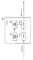
- FIG. 1 is a diagram illustrating a communication apparatus according to the first embodiment.
- the communication device 1 shown in FIG. 1 is a communication device that changes the communication speed according to the priority of data.
- the communication device 1 includes an input unit 1a, a priority determination unit 1b, a speed control unit 1c, and an output unit 1d.
- the input means 1a can be connected to another communication device or an apparatus having a communication function such as an information processing apparatus through a communication path.
- the input means 1a receives input data transmitted from these devices.
- the priority determination unit 1b determines the priority of the data input by the input unit 1a.
- the priority of data is, for example, a VLAN (Virtual LAN) tag of a LAN frame (Local Area Network frame) indicating a QoS (Quality of Service) setting indicated by a control signal included in information included in the data header,
- the priority is included in the ToS (Type of service) field of the IP (Internet Protocol address) packet, the destination address included in the LAN frame or IP packet, the destination port number included in the IP packet, etc. Can be determined based on information indicating whether or not transmission is required.
- QoS is a technology that reserves a bandwidth for a specific communication and guarantees a certain communication speed, and is a service that prevents communication delays and stops, such as real-time delivery of audio and video and videophones. Used.
- Examples of the QoS standard include IEEE 802.1p and IEEE 802.11e.
- the speed control means 1c sets the communication speed of the data output from the output means 1d faster when the priority of the data determined by the priority determination means 1b is higher than a predetermined value. On the other hand, when the priority of the data determined by the priority determination unit 1b is lower than a predetermined value, the speed control unit 1c sets the communication speed of the data output from the output unit 1d to be slow. Thereby, data can be transmitted and received at a communication speed corresponding to the determined priority.
- the output unit 1d outputs output data at the set communication speed. Data output from the output unit 1d is transferred to another communication device or the like through a communication path. As a result, by changing the communication speed based on the priority of data communication, the data communication speed of low priority data is suppressed, thereby rationally reducing high-speed communication with high power consumption and saving power. It becomes possible to plan.
- the communication apparatus is assumed to be a layer 2 switch, particularly a layer 2 switch that relays a data link layer packet based on a MAC address (Media Access Control address).
- MAC address Media Access Control address
- the present invention can also be applied to an IP router or a layer 3 switch that relays a network layer packet based on an IP address.
- the unit of layer 2 data in the OSI (Open Systems Interconnection) reference model is sometimes referred to as a packet, but in the second embodiment, for the sake of convenience of description, all of the units are expressed as a single frame.
- FIG. 2 is a diagram illustrating an overall configuration of a communication system according to the second embodiment.
- a plurality of layer 2 switches relay data link layer frames so that data can be transmitted and received between information processing apparatuses.
- the communication system shown in FIG. 2 includes switches 100, 100a, 100b, 100c, 100d and information processing devices 40, 61, 62, 63, 64, 65, 66.
- the switches 100, 100a, 100b, 100c, and 100d are layer 2 switches.
- the switches 100a, 100b, 100c, and 100d are configured in the same manner as the switch 100, and have equivalent functions.
- the switch 100 is connected to the information processing apparatus 40 and the switches 100a and 100b.
- the switch 100b is connected to the switches 100c and 100d.
- the information processing devices 61 and 62 are connected to the switch 100a.
- the information processing devices 63 and 64 are connected to the switch 100c.
- the information processing devices 65 and 66 are connected to the switch 100d.
- the information processing apparatus 40 is connected to the switch 100.
- the two switches or the switch and the information processing apparatus are connected by one or more physical links (network cables) such as a LAN.
- the switches 100, 100a, 100b, 100c, and 100d relay the frame from the source information processing apparatus to the destination information processing apparatus according to the address included in the frame. For example, when the information processing apparatus 40 transmits a frame to the information processing apparatus 63, the frame is relayed in the order of the switch 100, the switch 100b, and the switch 100c.
- FIG. 3 is a diagram illustrating a hardware configuration of the switch according to the second embodiment.
- FIG. 3 shows the internal configuration of the switch 100, but the switches 100a, 100b, 100c, and 100d can be realized with the same configuration.
- the switch 100 includes a central processing unit (CPU) 101, interface cards 102a, 102b, 102c, and 102d, a switch card 103, a table storage memory 104, a port monitoring unit 105, and a bus 106.
- CPU central processing unit
- the CPU 101 controls the entire switch 100.
- the CPU 101 executes processing by a program.
- the CPU 101 executes a program similarly held in the memory using data held in a memory (not shown).
- the CPU 101 receives a command transmitted from the information processing apparatus 40 used by the administrator via a communication interface (not shown), and returns an execution result for the command to the information processing apparatus 40.
- the table storage memory 104 stores a plurality of tables.
- the table stored in the table storage memory 104 includes a table for managing the configuration of the logical link, a table for determining a frame transfer destination within the logical link, and a table for storing information indicating the frame transfer destination. It is.
- the CPU 101, the interface cards 102a, 102b, 102c, and 102d, the switch card 103, the table storage memory 104, and the port monitoring unit 105 are connected to each other via the bus 106.
- Each of the interface cards 102a, 102b, 102c, and 102d has a plurality of (for example, eight) communication ports. One physical link can be connected to each communication port.
- the interface cards 102a, 102b, 102c, and 102d monitor the respective communication ports and acquire frames. Note that the interface cards 102a, 102b, 102c, and 102d have a buffer that temporarily holds frames in preparation for the case where frames arrive at a plurality of communication ports at the same time. Then, the interface cards 102a, 102b, 102c, and 102d send the acquired frame to the switch card 103.
- the switch card 103 has a learning table (not shown).
- the switch card 103 stores the transmission source address of the frame received in the past and the identification information of the communication port or logical link from which the frame has arrived in association with each other in the learning table. This learning table is updated by the switch card 103 as needed.
- the switch card 103 When the switch card 103 receives a frame from any one of the interface cards 102a, 102b, 102c, and 102d, the switch card 103 refers to the learning table and determines the transfer destination of the frame.
- the switch card 103 refers to the table stored in the table storage memory 104, and the specific interface cards 102a, 102b, 102c, 102d used for transfer and Determine the communication port. Thereafter, the switch card 103 sends the frame to the determined interface cards 102a, 102b, 102c, and 102d.
- the interface cards 102a, 102b, 102c, and 102d that have received the frame output the received frame from the determined communication port to the transmission destination.
- the port monitoring unit 105 monitors the communication ports of the interface cards 102a, 102b, 102c, and 102d. When the port monitoring unit 105 detects a failure or recovery of the physical link connected to the communication ports of the interface cards 102a, 102b, 102c, and 102d, the port monitoring unit 105 notifies the CPU 101 accordingly.
- FIG. 4 is a diagram illustrating an example of a data structure of a frame according to the second embodiment.
- the frame shown in FIG. 4 is connected to the switches 100a, 100b, etc. via the communication ports of the interface cards 102a, 102b, 102c, 102d described above in FIG. 3 of the switch 100 described in FIG. Sent and received.
- the frame shown in FIG. 4 includes a preamble, a destination MAC address, a transmission source MAC address, a TPID (Tag Protocol Identifier), a VLAN tag, a type, a payload, and an FCS (Frame Check Sequence). Have. Further, the VLAN tag has a priority, a CFI (Canonical Format Indicator), and a VLAN ID.
- the preamble, the destination MAC address, the source MAC address, the TPID, the VLAN tag, and the type are used as a header portion having control information.
- the payload is the payload part
- the FCS is the FCS part.
- the preamble is an 8-byte area having a bit string for notifying the start of frame transmission and giving timing for synchronization.
- the destination MAC address is a 6-byte area indicating an address that uniquely identifies a communication interface included in a destination information processing apparatus.
- the transmission source MAC address is a 6-byte area indicating an address that uniquely identifies the communication interface of the transmission source information processing apparatus.
- the TPID is a 2-byte area indicating the type of the frame (for example, whether it is a VLAN frame or a normal frame).
- the VLAN tag is a 2-byte area indicating a uniquely determined value assigned to each logical network when one network is divided into a plurality of logical networks.
- the priority of the VLAN tag is a 3-bit area indicating the priority of IEEE 802.1p.
- the priority indicates the priority level of the frame used for setting the priority of traffic in eight stages.
- the CFI is a 1-bit area that specifies a MAC address notation format (CSMA / CD (Carrier Sense Multiple Access / Collision Detection) format or FDDI (Fiber-Distributed Data Interface) format).
- the VLAN ID is a 12-bit area indicating the VLAN to which the frame belongs.
- the type is a 2-byte area that specifies the protocol to be used.
- the payload is a variable-length area having a data body to be transmitted / received. For example, an IP frame is divided into a predetermined data length.
- the FCS is a 4-byte area indicating a value used for detecting an error in a received frame.
- the data structure of the frame can be variously modified according to the network operation mode. For example, information other than that shown in FIG. 4 may be added. On the other hand, some of the information shown in FIG. 4 may be omitted.
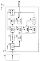
- FIG. 5 is a block diagram illustrating a configuration of the switch according to the second embodiment. 5 shows the function of the switch 100, the other switches 100a, 100b, 100c, and 100d described above with reference to FIG. 2 are also realized by the same configuration as the switch 100 and have the same function.
- the switch 100 transmits a frame according to the priority of the flow of data indicated by the frame into which the data is divided based on control information included in the data to be transmitted / received such as QoS. Change the communication speed.
- the switch 100 includes an input unit 111, a priority determination unit 112, a speed control unit 113, and an output unit 114.
- the switch 100 of this embodiment is a layer 2 switch, and transmits and receives data divided into a plurality of frames.
- the frame into which the data is divided has control information used for data transfer in the header portion.
- the control information included in the header portion includes priority information indicating priority in data communication and destination address information indicating the destination MAC address of the frame.
- the destination address included in the frame is a MAC address.
- the input unit 111 can be connected to other switches and information processing devices having communication functions such as other communication devices and information processing devices by physical links such as a LAN.
- the input unit 111 receives data transmitted from these devices as an input frame in a frame format.
- the priority determination unit 112 determines the priority of the flow of data input in the frame format by the input unit 111.
- the priority determination unit 112 transmits the data flow at a high speed, such as the priority included in the ToS field, the destination MAC address, and the like indicated by the control signal included in the information included in the frame header. It is determined based on information indicating whether or not it is necessary to do so.
- the priority determination unit 112 determines that the priority value (described above in FIG. 4) included in the control information of the header portion of the data frame input from the input unit 111 is higher than a predetermined threshold (predetermined value). Determines the priority of the data flow high. On the other hand, when the priority value included in the control information in the header portion of the data frame input from the input unit 111 is lower than a predetermined value, the priority determination unit 112 determines the data flow priority to be low. .
- a predetermined threshold predetermined value
- the priority determination unit 112 when the destination MAC address included in the control information of the header portion of the frame of the data input from the input unit 111 indicates a predetermined address such as the MAC address of the transmission destination, The priority of the data flow is determined to be high regardless of the value of. On the other hand, when the destination MAC address included in the control information of the header portion of the data frame input from the input unit 111 is not a predetermined address, the priority determination unit 112 determines the priority of the data flow to be low. Thereby, when communicating with a predetermined
- the priority determination unit 112 may indicate the priority determination result in, for example, three levels such as “low”, “medium”, and “high”, or three or more levels.
- the speed control unit 113 sets the communication speed of the data output from the output unit 114 faster.
- the speed control unit 113 sets the communication speed of the data output from the output unit 114 to be slow. Thereby, data can be transmitted and received at a communication speed corresponding to the determined priority.
- the speed control unit 113 increases the communication speed of the data output from the output unit 114 (for example, , 1000BASE-TX).
- the speed control unit 113 decreases the communication speed of the data output from the output unit 114 (for example, 100BASE ⁇ TX) Set.
- the output unit 114 outputs the data as an output frame in a frame format at the set communication speed.
- the data output from the output unit 114 is transferred to another switch or information processing apparatus through a physical link such as a LAN.
- the output unit 114 temporarily disconnects a link established between output ports 141, 142, 143,... Described later in FIG.
- the data communication speed is changed to the communication speed set by the speed control unit 113.
- the priority is determined based on the information of the header part of the frame input to the switch 100.
- the priority is not limited to this, but based on the information of the header part of the frame output from the switch 100. The priority may be determined.
- FIG. 6 is a diagram illustrating an outline of the switch according to the second embodiment. 2, the switch 100 described above distributes the input frame input from the input port 121 to any one of the output ports 141, 142, 143,... Output as a packet.
- the input port 121 is a port to which a frame is input.
- the switch unit 131 distributes the frame to the output ports 141, 142, 143,... According to the destination indicated in the header of the frame.
- the output ports 141, 142, 143,... Are ports from which a frame input from the input port 121 is output. Thereby, the frame input to the switch 100 is relayed toward the destination.
- FIG. 7 is a block diagram illustrating the configuration of the input port according to the second embodiment.
- the input port 121 is connected to the switch unit 131 and transfers the flow input to the switch 100 to the switch unit 131.
- the input port 121 includes a flow detection unit 121a, a bandwidth monitoring unit 121b, a marker unit 121c, and a priority designation unit 121d.
- the flow detector 121a detects the input flow based on control information in the header portion of the frame.
- the bandwidth monitoring unit 121b monitors the bandwidth of the flow input to the input port 121.
- the marker unit 121c rewrites the priority of the detected flow. As a result, the priority setting of the data flow can be changed.
- the priority (described above in FIG. 4) is rewritten.
- the present invention is not limited to this, and when the switch 100 is a layer 3 switch or the like and a packet is input, the priority included in the ToS field included in the packet of the input flow may be rewritten.
- DSCP DiffServ Code Point
- FIG. 8 is a block diagram illustrating a configuration of an output port according to the second embodiment. As described above with reference to FIG. 6, the output ports 141, 142, 143,... Are connected to the switch unit 131. Output to the information processing device.
- the output port 141 includes a flow detection unit 141a, a bandwidth monitoring unit 141b, a marker unit 141c, a priority designation unit 141d, a priority detection unit 141e, a link confirmation unit 141f, a link control unit 141g, a PHY unit 141h, a discard control unit 141k, It has a shaper unit 141m and an output queue unit 141p.
- the flow detection unit 141a detects the flow transferred from the switch unit 131 based on the control information in the header portion of the frame.
- the bandwidth monitoring unit 141b monitors the bandwidth of the flow output from the output port 141.
- the marker unit 141c rewrites the priority of the detected flow.
- the priority specifying unit 141d determines the output priority of the flow and the queuing priority when stored in the queue.
- the priority detection unit 141e detects the priority indicated by the frame determined by the priority specification unit 141d, and controls the link confirmation unit 141f and the link control unit 141g.
- the link confirmation unit 141f confirms the state of a link with another information processing apparatus or switch connected to the output port 141 and maintains the previous link state data.
- the link control unit 141g changes the communication speed of the link through which data is transmitted. At this time, the link control unit 141g temporarily disconnects the link established with the data transmission destination, and then establishes a new communication speed link with the data transmission destination. Change the link communication speed.
- the PHY unit 141h is located in the first layer of the OSI reference model and is a physical connection part of the network.
- the discard control unit 141k controls whether the frame is queued or discarded.
- the shaper unit 141m controls the frame output order and output band.
- the output queue unit 141p temporarily stores data waiting for output. The stored data waiting for output is read based on a certain rule, and the read data is then output.
- FIGS. 9 and 10 are flowcharts showing the procedure of the speed control process.
- the speed control process shown in FIGS. 9 and 10 is a process in which the switch 100 (described above in FIG. 2) controls the link speed according to the priority of the data flow.
- the speed control process of the present embodiment is executed in response to the start of communication of the switch 100.
- the communication speed of the link of the switch 100 is two types, “slow (eg, 100BASE-TX)” and “speed (eg, 1000BASE-TX)”.
- Step S11 The priority determination unit 112 (described above in FIG. 5) executes a priority determination process (described later in FIG. 12).
- Step S12 The priority determination unit 112 determines whether or not the priority determination result by the priority determination processing in step S11 is “high”. If the determination result is “high”, the process proceeds to step S13. On the other hand, if the determination result is not “high”, the process proceeds to step S21 (FIG. 10).
- Step S13 The speed control unit 113 (described above in FIG. 5) confirms the link speed.
- Step S14 The speed control unit 113 determines whether or not the speed of the link confirmed in step S13 is “speed”. If the speed of the link is “fast”, the process proceeds to step S11. On the other hand, if the link speed is not “fast”, the process proceeds to step S15.
- Step S15 The speed control unit 113 sets the speed of the link to “speed”. Thereafter, the process proceeds to step S11.
- the speed control unit 113 checks the speed of the link.
- Step S22 The speed control unit 113 determines whether or not the speed of the link confirmed in Step S21 is “slow”. If the link speed is “slow”, the process proceeds to step S11 (FIG. 9). On the other hand, if the link speed is not “slow”, the process proceeds to step S23.
- Step S23 The speed controller 113 sets the speed of the link to “slow”. Thereafter, the process proceeds to step S11.
- the link communication speed of the switch 100 may use speed standards other than the above two types, and may further provide three or more speed stages.
- the priority of the data flow is determined for all frames.
- the present invention is not limited to this, and it may be determined only for a frame extracted by a predetermined rule.
- the priority of the data flow may be determined using the first frame of the flow.
- FIG. 11 is a flowchart illustrating a procedure of priority determination processing according to the second embodiment.
- the priority determination process illustrated in FIG. 11 is a process of determining the priority of the data flow based on the flow frame input to the switch 100.
- the priority determination process of the present embodiment is called and executed in step S11 of the speed control process (described above in FIGS. 9 and 10).
- the priority determination unit 112 acquires the priority of the frame of the flow input to the switch 100.
- the priority determination unit 112 determines whether or not the priority value acquired in step S31 is a predetermined value (for example, 6) or more. If the priority value is greater than or equal to the predetermined value, the process proceeds to step S34. On the other hand, if the priority value is less than the predetermined value, the process proceeds to step S33.
- Step S33 The priority determination unit 112 determines whether or not the destination MAC address indicated by the control information in the header portion of the flow frame is a predetermined MAC address. If the destination MAC address is a predetermined MAC address, the process proceeds to step S34. On the other hand, if the destination MAC address is not a predetermined MAC address, the process proceeds to step S35.
- Step S34 The priority determination unit 112 sets the priority determination result to “high”. Thereafter, the process returns.
- Step S35 The priority determination unit 112 sets the priority determination result to “low”. Thereafter, the process returns.
- the link speed is changed according to the priority determined based on the priority and the destination MAC address included in the control information of the header part of the frame.
- a method for adjusting the data delay when changing the link speed a method is provided in which a transmission / reception buffer is provided to accumulate data, and data transmission / reception is resumed after the link is reestablished at the changed speed.
- Two types of methods can be used: a method using retransmission at the time of a transmission / reception error by a communication protocol. Since these are general functions in switches and information processing apparatuses that communicate with the switches, they can be realized without adding new functions. Thereby, power saving of the switch 100 can be achieved economically.
- a switch will be described by exemplifying a layer 3 switch that relays a network layer packet based on an IP address. Further, in the third embodiment, for convenience of explanation, the unit of layer 3 data in the OSI reference model is all expressed in a packet.
- TCP Transmission Control Protocol
- UDP User Datagram Protocol
- FIG. 12 is a block diagram illustrating a configuration of the switch according to the third embodiment.
- the switch 200 according to the present embodiment illustrated in FIG. 12 can be used by connecting to another switch or an information processing apparatus in a system similar to the system illustrated in FIG.
- the switch 200 transmits a packet according to the priority of the flow of data indicated by the packet into which the data is divided based on control information included in the data to be transmitted / received such as QoS. Change the communication speed.
- the switch 200 includes an input unit 211, a priority determination unit 212, a speed control unit 213, and an output unit 214.
- the switch 200 is a layer 3 switch, and transmits and receives data divided into a plurality of packets.
- the packet into which the data is divided has control information used for data transfer in the header portion.
- the control information included in the header portion includes priority information indicating the priority in data communication and a destination IP address indicating a data transmission destination address.
- the input unit 211 can be connected to another switch or information processing apparatus having a communication function by a physical link such as a LAN.
- the input unit 211 receives data transmitted from these devices as an input packet in a packet format.
- the priority determination unit 212 determines the priority of the flow of data input in the packet format by the input unit 211.
- the priority determination unit 212 indicates the priority of the data flow, the priority included in the ToS field, the destination IP address, and the port number of the packet transmission destination indicated by the control signal included in the information included in the packet header. The determination is based on information indicating whether the data needs to be transmitted at high speed, such as the port number information indicated.
- the priority determination unit 212 determines that the priority of the data flow is high when the priority of the control information in the header portion of the data packet input from the input unit 211 is higher than a predetermined value. On the other hand, when the priority included in the control information of the header portion of the data packet input from the input unit 211 is lower than a predetermined value, the priority determination unit 212 determines the priority of the data flow to be low.
- the priority determination unit 212 when the destination IP address included in the control information of the header portion of the data packet input from the input unit 211 indicates a predetermined address, regardless of the priority value, A high priority is determined. On the other hand, when the destination IP address included in the control information of the header portion of the data packet input from the input unit 211 is not a predetermined address, the priority determination unit 212 determines the priority of the data flow to be low.
- the IP address indicates the information processing apparatus of the other party that is performing communication. That is, in this embodiment, the priority can be determined according to each information processing apparatus of the communication partner.
- the priority determination unit 212 determines whether or not the destination port number information included in the control information of the header portion of the data packet input from the input unit 211 indicates a predetermined port number, regardless of the priority value. Determine the priority of the data flow. On the other hand, when the destination port number information included in the control information of the header portion of the data packet input from the input unit 211 is not a predetermined port number, the priority determination unit 212 determines the priority of the data flow. Judge low.
- the TCP and UDP port numbers indicate applications and services that operate on the information processing apparatus of the other party that is performing communication and process data to be transmitted and received.
- priority can be determined according to an application or service that processes transmitted / received data.
- FTP File Transfer Protocol
- FTP port numbers “20” and “21” are set in advance as predetermined port numbers.
- the determination result of the priority of the FTP packet becomes high.
- the communication speed of the link through which data is transmitted can be maintained.
- the communication speed of the link is lowered by lowering the priority of the packet with the port number “20”. Therefore, power saving can be achieved.
- the priority of the data flow can be determined by combining the information processing apparatus as the transmission destination with an application or service for processing data.
- the priority determination unit 212 may indicate the priority determination result in, for example, three levels such as “low”, “medium”, and “high”, or three or more levels.
- the speed control unit 213 sets the communication speed of the data output from the output unit 214 faster.
- the speed control unit 213 sets the communication speed of the data output from the output unit 214 to be slow. Thereby, data can be transmitted and received at a communication speed corresponding to the determined priority.
- the output unit 214 outputs data in the packet format as an output packet at the set communication speed.
- the data output from the output unit 214 is transferred to another switch or information processing apparatus through a physical link such as a LAN.
- the output unit 214 temporarily disconnects links established between a plurality of output ports (not shown) included in the output unit 214 and the data transmission destination, and the priority determination unit 212 sets the priority.
- the data communication speed is changed to the communication speed set by the speed control unit 213.
- the priority is determined based on the information of the header part of the packet input to the switch 200.
- the priority is not limited to this, but based on the information of the header part of the packet output from the switch 200. The priority may be determined.
- the switch 200 according to the present embodiment is a layer 3 switch, but is not limited to this, and may be a router or a device having a function equivalent to these.
- FIG. 13 illustrates an example data structure of a packet according to the third embodiment.
- the packet shown in FIG. 13 is the same as that of the second embodiment of the interface cards 102a, 102b, 102c, and 102d of the second embodiment described in FIG. 3 of the switch 100 described in FIG.
- the data is transmitted / received to / from other switches (not shown) via the same communication port.
- the packet shown in FIG. 13 has an IP header and a TCP header that both have control information.
- the IP header has a version number, header length, ToS field, packet length, identifier, flag, fragment offset, TTL (Time To Live), protocol number, header checksum, source IP address, and destination IP address.
- the ToS field has priority and others.
- the TCP header has a source port number, a destination port number, a sequence number, an acknowledgment number, a data offset, a reserved area, a code bit, a window size, a checksum, and an emergency pointer.
- the packet has a data field together with the IP header and the TCP header.
- the numbers in parentheses in FIG. 13 indicate the number of bits in each area.
- the version number is a 4-bit area indicating the version of the IP protocol. For example, in the IPv4 packet, the value of this area is 4, and in IPv6, the value of this area is 6. In this embodiment, an IPv4 packet will be described as an example.
- the header length is a 4-bit area for representing the size of the header portion of the packet.
- the ToS field is an 8-bit area indicating the priority of the packet data flow.
- the priority of the ToS field is a 3-bit area indicating the priority of the packet data flow.
- Others are 5-bit areas that can be used for other purposes. Note that, based on DSCP in DiffServ, the priority can be expanded to 6 bits together with 3 bits of the other 5 bits, and the identification information can be included in the priority.
- the packet length is a 16-bit area indicating the size of the entire packet in bytes.
- the identifier is a 16-bit area indicating a value for identifying a packet used in IP fragmentation.
- the flag is a 3-bit area indicating an instruction at the time of packet division / combination used in IP fragmentation.
- the fragment offset is a 13-bit area used in the IP fragmentation to indicate where the fragmented packet data is located in the original data.
- the TTL is an 8-bit area indicating the lifetime of the packet.
- the protocol number is an 8-bit area indicating the type of network protocol in the transport layer.
- the header checksum is a 16-bit area indicating the checksum of the IP header.
- the source IP address is a 32-bit area indicating the IP address of the source computer.
- the destination IP address is a 32-bit area indicating the IP address of the destination computer.
- the transmission source port number is a 16-bit area indicating the port number of the transmission source of the packet.
- the source application can be identified by the source port number.
- the destination port number is a 16-bit area indicating the port number of the packet transmission destination.
- the destination port number can identify the application that uses the packet data at the transmission destination.
- the sequence number is a 32-bit area indicating the order of data transmitted after being divided by a packet.
- the confirmation response number is an area indicated in the response packet, and is a 32-bit area indicating how far the transmission destination has received data.
- the data offset is a 4-bit area indicating the size of the TCP header.
- the reserved area is an unused 6-bit area.
- the code bit is a 6-bit area indicating various control flags.
- the window size is a 16-bit area indicating a receivable window size.
- the checksum is a 16-bit area indicating the checksum of the TCP header and data field.
- the urgent pointer is a 16-bit area indicating the position and size of the urgent data when the URG (urgent) flag indicating that the urgent data is included in the TCP packet is turned on.
- the data field is a variable-length area having a data body transmitted / received by an IP packet. It should be noted that various modifications of the data structure of the packet are conceivable depending on the network operation mode and the like. For example, information other than that shown in FIG. 13 may be added. On the other hand, some of the information shown in FIG. 13 may be omitted.
- FIG. 14 is a flowchart illustrating a procedure of priority determination processing according to the third embodiment.
- the priority determination process illustrated in FIG. 14 is a process of determining the priority of the data flow based on the flow packet input to the switch 200.
- the priority determination process of the present embodiment is a speed control process executed in the present embodiment as well as the priority determination process of the second embodiment shown in FIG. 11 (described above in FIGS. 9 and 10). Is called and executed in step S11.
- the priority determination unit 212 acquires the priority of the packet of the flow input to the switch 200.
- the priority determination unit 212 determines whether or not the priority value acquired in step S41 is a predetermined value (for example, 4) or more. If the priority value is greater than or equal to the predetermined value, the process proceeds to step S45. On the other hand, if the priority value is less than the predetermined value, the process proceeds to step S43.
- Step S43 The priority determination unit 212 determines whether or not the destination IP address indicated by the control information in the IP header portion of the flow packet is a predetermined IP address (eg, “192.1.1.1”). judge. If the destination IP address is a predetermined IP address, the process proceeds to step S44. On the other hand, if the destination IP address is not a predetermined IP address, the process proceeds to step S46.
- a predetermined IP address eg, “192.1.1.1”.
- Step S44 The priority determination unit 212 determines whether the destination port number indicated by the control information in the TCP header portion of the flow packet is a predetermined port number (for example, “20” or “21”). . If the destination port number is a predetermined port number, the process proceeds to step S45. On the other hand, if the destination port number is not the predetermined port number, the process proceeds to step S46.
- a predetermined port number for example, “20” or “21”.
- Step S45 The priority determination unit 212 sets the priority determination result to “high”. Thereafter, the process returns.
- Step S46 The priority determination unit 212 sets the priority determination result to “low”. Thereafter, the process returns.
- the switch 200 is a layer 3 switch or the like that transfers an IP packet
- the priority of the ToS field included in the IP packet is used, The same effects as in the embodiment can be obtained.
- the priority is determined based on the source port number or the destination port number, the priority can be determined according to the application used in the information processing apparatus on the client side. As a result, with respect to a packet of a flow for transmitting / receiving application data that requires a higher link speed, priority can be increased and data can be transmitted / received at high speed.
- an information processing apparatus that sets the link speed based on the priority indicated by the data link layer packet will be described by way of example.
- the link speed can also be set based on the priority shown.
- the unit of layer 2 data in the OSI reference model is sometimes called a packet, in the fourth embodiment, as in the second embodiment, for the sake of convenience, all the data are expressed in a unified manner. To do.
- FIG. 15 is a block diagram illustrating a configuration of the information processing apparatus according to the fourth embodiment.
- the information processing apparatus 300 according to the present embodiment illustrated in FIG. 15 can be used by being connected to a switch in a system similar to the system illustrated in FIG.
- the information processing apparatus 300 uses a frame according to the priority of the flow of data indicated by a frame into which data is divided based on control information included in data to be transmitted and received such as QoS. Change the communication speed at which is sent.
- the information processing apparatus 300 includes an input unit 311, a priority determination unit 312, a speed control unit 313, and an output unit 314.
- the information processing apparatus 300 can communicate with layer 2 frames, and transmits and receives data divided into a plurality of frames.
- the frame into which the data is divided has control information used for data transfer in the header portion.
- the control information included in the header portion includes priority information indicating priority in data communication and destination address information indicating the destination MAC address of the frame.
- the destination address included in the frame is a MAC address.
- the input unit 311 can be connected to another switch or information processing apparatus having a communication function through a physical link such as a LAN.
- the input unit 311 receives data transmitted from these devices as an input frame in a frame format.
- the priority determination unit 312 determines the priority of the flow of data input by the input unit 311 in the frame format.
- the priority determination unit 312 transmits the data flow priority at a high speed, such as the priority included in the ToS field, the destination MAC address, and the like indicated by the control signal included in the information included in the frame header. It is determined based on information indicating whether or not it is necessary to do so.
- the priority determination unit 312 performs the data flow when the priority value (described above in FIG. 4) included in the control information of the header portion of the frame of the data input from the input unit 311 is higher than a predetermined value. High priority is determined. On the other hand, when the priority value included in the control information in the header portion of the data frame input from the input unit 311 is lower than a predetermined value, the priority determination unit 312 determines the data flow priority to be low. .
- the priority determination unit 312 receives data when the destination MAC address included in the control information of the header portion of the frame of the data input from the input unit 311 indicates a predetermined address such as the MAC address of the transmission destination. The flow priority is determined to be high. On the other hand, when the destination MAC address included in the control information of the header part of the data frame input from the input unit 311 is not a predetermined address, the priority determination unit 312 determines the data flow priority to be low. Thereby, when communicating with a predetermined
- the priority determination unit 312 may indicate the priority determination result in, for example, three levels such as “low”, “medium”, and “high”, or three or more levels.
- the speed control unit 313 sets the communication speed of the data output from the output unit 314 faster.
- the speed control unit 313 sets the communication speed of the data output from the output unit 314 to be low.
- the output unit 314 outputs the data as an output frame in a frame format at the set communication speed.
- the data output from the output unit 314 is transferred to another switch or information processing apparatus through a physical link such as a LAN.
- the output unit 314 temporarily disconnects links established between a plurality of output ports (not shown) included in the output unit 314 and the data transmission destination, and the priority determination unit 312 determines the priority.
- the data communication speed is changed to the communication speed set by the speed control unit 313.
- the priority is determined based on the information of the header portion of the frame input to the information processing device 300.
- the priority is not limited to this, and the header portion of the frame output from the information processing device 300 is not limited thereto.
- the priority may be determined based on the information.
- the information processing apparatus 300 determines the priority of the data flow based on the layer 2 frame, but is not limited thereto, and may determine the priority of the data flow based on the layer 3 packet.
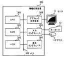
- FIG. 16 is a diagram illustrating a hardware configuration of the information processing apparatus according to the fourth embodiment.
- the information processing apparatus 300 shown in FIG. 16 is controlled by a CPU (Central Processing Unit) 301 as a whole.
- a RAM (Random Access Memory) 302 a hard disk drive (HDD: Hard Disk Drive) 303, a graphic processing device 304, an input interface 305, and a communication interface 306 are connected to the CPU 301 via a bus 307.
- the RAM 302 temporarily stores at least part of an OS (Operating System) program and application software program (application program) to be executed by the CPU 301.
- the RAM 302 stores various data necessary for processing by the CPU 301.
- the HDD 303 stores an OS and application programs.
- a monitor 11 is connected to the graphic processing device 304.
- the graphic processing device 304 displays an image on the screen of the monitor 11 in accordance with a command from the CPU 301.
- a keyboard 12 and a mouse 13 are connected to the input interface 305.
- the input interface 305 transmits a signal transmitted from the keyboard 12 or the mouse 13 to the CPU 301 via the bus 307.
- the communication interface 306 can be connected to a network (not shown).
- the communication interface 306 can transmit / receive data to / from another switch (for example, the switch 100 described above) or a computer via a network.
- FIG. 17 is a block diagram illustrating a configuration of the driver according to the fourth embodiment.
- a driver 351 functioning in the information processing apparatus 300 illustrated in FIG. 17 outputs a transmission frame transmitted from the information processing apparatus 300 to a switch or the like that transfers the frame to the destination.
- the driver 351 includes a flow detection unit 351a, a priority detection unit 351e, a link confirmation unit 351f, a link control unit 351g, and a PHY unit 351h.
- the flow detection unit 351a detects the flow transmitted from the information processing device 300 based on the control information in the header portion of the frame.
- the priority detection unit 351e detects the priority of the data flow from the control information in the header portion of the frame transmitted from the information processing device 300, and controls the link confirmation unit 351f and the link control unit 351g.
- the link confirmation unit 351f confirms the state of a link with another switch or the like connected to an output port (not shown) of the information processing apparatus 300 and maintains the previous link state data.
- the link control unit 351g changes the link communication speed.
- the PHY unit 351h is located in the first layer of the OSI reference model and is a physical connection part of the network.
- the communication flow can be set by setting the priority of the data flow. it can. That is, the information processing apparatus 300 can set the priority of the data flow according to the judgment of the user or application. Accordingly, the priority can be set more flexibly and in detail than when the switch or the like determines the priority of the data flow formally or mechanically according to the type of frame or packet, for example. .
- the information processing apparatus 300 since the information processing apparatus 300 has a function of setting the communication speed of the link based on the priority, the information processing apparatus in the communication path between the information processing apparatus 300 on the client side and the communication apparatus such as a switch.
- the link can be established at an appropriate communication speed from the time when data is transmitted from 300, and the power saving effect is further increased.
- the above processing functions can be realized by a computer.
- a program describing processing contents of functions that the switch 100, the switch 200, and the information processing apparatus 300 should have is provided.
- the above processing functions are realized on the computer.
- the program describing the processing content can be recorded on a computer-readable recording medium.
- the computer-readable recording medium include a magnetic recording device, an optical disk, a magneto-optical recording medium, and a semiconductor memory.
- Magnetic recording devices include HDDs, flexible disks (FD), magnetic tapes (MT) and the like.
- Optical discs include DVD (Digital Versatile Disc), DVD-RAM (Random Access Memory), CD-ROM (Compact Disc-Read Only Memory), CD-R (Recordable) / RW (ReWritable), and the like.
- Magneto-optical recording media include MO (Magneto-Optical Disk).
- a portable recording medium such as a DVD or CD-ROM in which the program is recorded is sold. It is also possible to store the program in a server computer and transfer the program from the server computer to another computer via a network.
- the computer that executes the program stores, for example, the program recorded on the portable recording medium or the program transferred from the server computer in its own storage device. Then, the computer reads the program from its own storage device and executes processing according to the program. The computer can also read the program directly from the portable recording medium and execute processing according to the program. Further, each time the program is transferred from the server computer, the computer can sequentially execute processing according to the received program.
- the disclosed communication device, information processing device, and communication control method have been described based on the illustrated embodiment, but the configuration of each unit can be replaced with any configuration having a similar function.
- any other component or process may be added to the disclosed technology.
- the disclosed technique may be a combination of any two or more of the above-described embodiments.
Landscapes
- Engineering & Computer Science (AREA)
- Computer Networks & Wireless Communication (AREA)
- Signal Processing (AREA)
- Computer Security & Cryptography (AREA)
- Small-Scale Networks (AREA)
- Data Exchanges In Wide-Area Networks (AREA)
Abstract
データに応じて通信速度を変更することによって省電力化を図る。 入力手段(1a)は、データが入力される。優先度判定手段(1b)は、入力手段(1a)によって入力されたデータの優先度を判定する。速度制御手段(1c)は、優先度判定手段(1b)によって判定されたデータの優先度が所定値より高い場合には、出力手段(1d)から出力されるデータの通信速度を速く設定する。一方、速度制御手段(1c)は、優先度判定手段(1b)によって判定されたデータの優先度が所定値より低い場合には、出力手段(1d)から出力されるデータの通信速度を遅く設定する。出力手段(1d)は、設定された通信速度でデータを出力する。
Description
本件は通信装置、情報処理装置および通信制御方法に関する。
近年、地球環境問題やエネルギー問題に対する意識の高まりにより、エナジースター(Energy Star)等のように、一般的に様々な装置に対して省エネルギー化が求められている。これは、通信装置についても例外ではなく、電力の低減が求められている。
なお、例えば、有線LAN(Local Area Network)のような通信方式は、一般的にリンク(link)の通信速度が1回決定されると、ネットワーク上のパケット量に通信速度が保持され続ける。そして、この通信速度は、ユーザが自らリンクスピードの変更を行わない限り、そのまま保持され続ける。
ここで、例えば、有線LANにおいて通信速度が速い1000BASE-Tと通信速度が遅い100BASE-TXとの間において、LANチップの消費電力が2倍以上の差が生じる場合もある。このため、このような通信方式で常時の通信を行っている場合、ネットワークにおいて品質を保証する通信(さらに、データ通信自体)が常に行われているとは限らないにもかかわらず、消費電力の大きい高速の通信が可能な状態を維持することは、無駄な電力消費であり、省エネルギーの観点から好ましくないという問題点がある。
本発明はこのような点に鑑みてなされたものであり、データの通信の優先度に応じて通信速度を変更することによって、電力消費量が多い高速通信を合理的に削減して省電力化を図る通信装置、情報処理装置および通信制御方法を提供することを目的とする。
開示の通信装置は、データが入力される入力手段と、前記入力手段によって入力された前記データの優先度を判定する優先度判定手段と、設定された通信速度で前記データを出力する出力手段と、前記優先度判定手段によって判定された前記データの前記優先度が所定値より高い場合には、前記出力手段から出力される前記データの前記通信速度を速く設定し、一方、前記優先度判定手段によって判定された前記データの前記優先度が前記所定値より低い場合には、前記出力手段から出力される前記データの前記通信速度を遅く設定する速度制御手段とを有する。
開示の通信装置、情報処理装置および通信制御方法によれば、データの通信の優先度に基づいて通信速度を変更することによって、優先度の低いデータの通信速度を抑制することで省電力化を図ることが可能になる。
本発明の上記および他の目的、特徴および利点は本発明の例として好ましい実施の形態を表す添付の図面と関連した以下の説明により明らかになるであろう。
以下、本発明の実施の形態について、図面を参照して説明する。
[第1の実施の形態]
図1は、第1の実施の形態の通信装置を示す図である。図1に示す通信装置1は、データの優先度に応じて通信速度を変更する通信装置である。通信装置1は、入力手段1a、優先度判定手段1b、速度制御手段1c、出力手段1dを有する。
[第1の実施の形態]
図1は、第1の実施の形態の通信装置を示す図である。図1に示す通信装置1は、データの優先度に応じて通信速度を変更する通信装置である。通信装置1は、入力手段1a、優先度判定手段1b、速度制御手段1c、出力手段1dを有する。
入力手段1aは、他の通信装置や情報処理装置等の通信機能を有する装置と通信路によって接続可能である。入力手段1aは、これらの装置から送信された入力データが入力される。
優先度判定手段1bは、入力手段1aによって入力されたデータの優先度を判定する。データの優先度は、例えば、データのヘッダが有する情報に含まれている制御信号が示す、QoS(Quality of Service)の設定を示すLANフレーム(Local Area Network frame)のVLAN(Virtual LAN)タグやIP(Internet Protocol address)パケット(packet)のToS(Type of Service)フィールドに含まれるプライオリティ、同じくLANフレームやIPパケットに含まれる宛先アドレス、IPパケットに含まれる宛先ポート番号等の、そのデータが高速で送信する必要があるか否かを示す情報に基づいて判定することができる。
ここで、QoSは、ある特定の通信のための帯域を予約し、一定の通信速度を保証する技術であり、音声や動画のリアルタイム配信やテレビ電話など、通信の遅延や停止を防ぎたいサービスで用いられる。QoSの標準規格には、IEEE802.1pや、IEEE802.11e等がある。
速度制御手段1cは、優先度判定手段1bによって判定されたデータの優先度が所定値より高い場合には、出力手段1dから出力されるデータの通信速度を速く設定する。一方、速度制御手段1cは、優先度判定手段1bによって判定されたデータの優先度が所定値より低い場合には、出力手段1dから出力されるデータの通信速度を遅く設定する。これにより、判定された優先度に応じた通信速度でデータを送受信することができる。
出力手段1dは、設定された通信速度で出力データを出力する。出力手段1dから出力されたデータは、通信路を通じて他の通信装置等に転送される。
これにより、データの通信の優先度に基づいて通信速度を変更することによって、優先度の低いデータの通信速度を抑制することで、電力消費量が多い高速通信を合理的に削減して省電力化を図ることが可能になる。
これにより、データの通信の優先度に基づいて通信速度を変更することによって、優先度の低いデータの通信速度を抑制することで、電力消費量が多い高速通信を合理的に削減して省電力化を図ることが可能になる。
[第2の実施の形態]
第2の実施の形態では通信装置をレイヤ(layer)2スイッチとして、特にMACアドレス(Media Access Control address)に基づいてデータリンク層のパケットを中継するレイヤ2スイッチを例示して説明するが、これに制限されず、例えば第3の実施の形態で後述するように、IPアドレスに基づいてネットワーク層のパケットを中継するIPルーターやレイヤ3スイッチにも適用することができる。また、OSI(Open Systems Interconnection)参照モデルにおけるレイヤ2のデータの単位を、パケットと呼ぶこともあるが、第2の実施の形態では、説明の便宜上、すべてフレームに統一して表現する。
第2の実施の形態では通信装置をレイヤ(layer)2スイッチとして、特にMACアドレス(Media Access Control address)に基づいてデータリンク層のパケットを中継するレイヤ2スイッチを例示して説明するが、これに制限されず、例えば第3の実施の形態で後述するように、IPアドレスに基づいてネットワーク層のパケットを中継するIPルーターやレイヤ3スイッチにも適用することができる。また、OSI(Open Systems Interconnection)参照モデルにおけるレイヤ2のデータの単位を、パケットと呼ぶこともあるが、第2の実施の形態では、説明の便宜上、すべてフレームに統一して表現する。
図2は、第2の実施の形態の通信システムの全体構成を示す図である。本実施の形態の通信システムは、情報処理装置間でデータの送受信を行えるように、複数のレイヤ2スイッチがデータリンク層のフレームを中継するものである。
図2に示す通信システムは、スイッチ100,100a,100b,100c,100dと情報処理装置40,61,62,63,64,65,66とで構成される。スイッチ100,100a,100b,100c,100dは、レイヤ2スイッチである。スイッチ100a,100b,100c,100dは、スイッチ100と同様に構成されており、同等の機能を有する。
スイッチ100は、情報処理装置40、スイッチ100a,100bと接続されている。スイッチ100bは、スイッチ100c,100dと接続されている。情報処理装置61,62は、スイッチ100aと接続されている。情報処理装置63,64は、スイッチ100cと接続されている。情報処理装置65,66は、スイッチ100dと接続されている。情報処理装置40は、スイッチ100と接続されている。2つのスイッチ間またはスイッチと情報処理装置の間は、例えばLAN等の1つ以上の物理リンク(ネットワークケーブル)で接続されている。
スイッチ100,100a,100b,100c,100dは、フレームに含まれるアドレスに従って、送信元の情報処理装置から宛先の情報処理装置まで、フレームを中継する。例えば、情報処理装置40が情報処理装置63へフレームを送信する場合、スイッチ100、スイッチ100b、スイッチ100cの順にフレームが中継される。
図3は、第2の実施の形態のスイッチのハードウェア構成を示す図である。図3は、スイッチ100の内部構成を示したものであるが、スイッチ100a,100b,100c,100dも同様の構成で実現できる。スイッチ100は、CPU(Central Processing Unit)101、インタフェースカード102a,102b,102c,102d、スイッチカード103、テーブル記憶メモリ104、ポート監視部105、バス106を有している。
CPU101は、スイッチ100全体を制御している。CPU101は、プログラムによる処理を実行する。CPU101は、図示しないメモリに保持されたデータを用いて、同じくメモリに保持されたプログラムを実行する。CPU101は、図示しない通信インタフェースを介して、管理者が使用する情報処理装置40から送信されるコマンドを受信すると共に、コマンドに対する実行結果を情報処理装置40に応答する。
テーブル記憶メモリ104は、複数のテーブルを記憶している。テーブル記憶メモリ104に記憶されるテーブルには、論理リンクの構成を管理するテーブル、論理リンク内でのフレームの転送先を決定するためのテーブル、フレームの転送先を示す情報を記憶するテーブルが含まれる。
バス106により、CPU101、インタフェースカード102a,102b,102c,102d、スイッチカード103、テーブル記憶メモリ104、ポート監視部105が互いに接続されている。
インタフェースカード102a,102b,102c,102dは、それぞれ複数個(例えば、8個)の通信ポートを有している。それぞれの通信ポートには、1つの物理リンクを接続できる。インタフェースカード102a,102b,102c,102dは、それぞれの通信ポートを監視してフレームを取得する。なお、インタフェースカード102a,102b,102c,102dは、複数の通信ポートに同時にフレームが到来した場合に備えて、フレームを一時的に保持するバッファを内部に有している。そして、インタフェースカード102a,102b,102c,102dは、取得したフレームをスイッチカード103に送る。
スイッチカード103は、図示しない学習テーブルを有している。スイッチカード103は、学習テーブルに、過去に受信したフレームの送信元アドレスと、そのフレームが到来した通信ポートまたは論理リンクの識別情報とを対応付けて記憶している。この学習テーブルは、スイッチカード103によって随時更新される。
そして、スイッチカード103は、インタフェースカード102a,102b,102c,102dのいずれかからフレームを受け取ると、学習テーブルを参照して、そのフレームの転送先を決定する。ここで、決定した転送先が論理リンクである場合、スイッチカード103は、テーブル記憶メモリ104に記憶されたテーブルを参照して、転送に使用する具体的なインタフェースカード102a,102b,102c,102dおよび通信ポートを決定する。その後、スイッチカード103は、フレームを、決定したインタフェースカード102a,102b,102c,102dに送る。
フレームを受け取ったインタフェースカード102a,102b,102c,102dは、受け取ったフレームを、決定された通信ポートから送信先に出力する。
ポート監視部105は、インタフェースカード102a,102b,102c,102dの通信ポートを監視する。そして、ポート監視部105は、インタフェースカード102a,102b,102c,102dの通信ポートに接続された物理リンクの故障や復旧を検出すると、CPU101にその旨を通知する。
ポート監視部105は、インタフェースカード102a,102b,102c,102dの通信ポートを監視する。そして、ポート監視部105は、インタフェースカード102a,102b,102c,102dの通信ポートに接続された物理リンクの故障や復旧を検出すると、CPU101にその旨を通知する。
図4は、第2の実施の形態のフレームのデータ構造例を示す図である。本実施の形態では、図4に示すフレームが、図2において前述したスイッチ100の図3において前述したインタフェースカード102a,102b,102c,102dの通信ポートを介して、スイッチ100a,100b等との間で送受信される。
図4に示すフレームは、プリアンブル(preamble)、宛先MACアドレス、送信元MACアドレス、TPID(Tag Protocol Identifier:タグ・プロトコル(protocol)識別子)、VLANタグ、タイプ、ペイロードおよびFCS(Frame Check Sequence)を有する。また、VLANタグは、プライオリティ(priority)、CFI(Canonical Format Indicator)、VLAN IDを有する。
ここで、プリアンブル、宛先MACアドレス、送信元MACアドレス、TPID、VLANタグ、タイプを、制御情報を有するヘッダ部とする。また、ペイロードを、ペイロード部とし、FCSを、FCS部とする。
プリアンブルは、フレームの送信の開始を知らせるとともに、同期をとるタイミングを与えるためのビット列を有する8バイトの領域である。宛先MACアドレスは、送信先の情報処理装置が有する通信インタフェースを一意に識別するアドレスを示す6バイトの領域である。送信元MACアドレスは、送信元の情報処理装置が有する通信インタフェースを一意に識別するアドレスを示す6バイトの領域である。TPIDは、当該フレームの種類(例えば、VLANのフレームであるか通常のフレームであるか)を示す2バイトの領域である。
VLANタグは、1つのネットワークを複数の論理的なネットワークに分割して運用する場合に、個々の論理的なネットワークに割り当てられる一意に定められた値を示す2バイトの領域である。
VLANタグが有するプライオリティは、IEEE802.1pの優先順位を示す3ビットの領域である。プライオリティは、トラフィックの優先順位設定に使用されるフレームの優先順位レベルを8段階で示す。CFIは、MACアドレスの表記形式(CSMA/CD(Carrier Sense Multiple Access/Collision Detection)形式か、またはFDDI(Fiber-Distributed Data Interface)形式か)を指定する1ビットの領域である。VLAN IDは、フレームが所属するVLANを示す12ビットの領域である。
タイプは、使用するプロトコルを指定する2バイトの領域である。ペイロードは、送受信するデータ本体を有する可変長の領域であり、例えば、IPフレームを所定のデータ長に分割したものである。FCSは、受信したフレームの誤りを検出するために用いられる値を示す4バイトの領域である。
なお、フレームのデータ構造は、ネットワークの運用形態等に応じて、種々の変形例が考えられる。例えば、図4に示したもの以外の情報が付加される場合もある。一方、図4に示した情報の一部が省略される場合もある。
図5は、第2の実施の形態のスイッチの構成を示すブロック図である。なお、図5ではスイッチ100の機能を示しているが、図2において前述した他のスイッチ100a,100b,100c,100dもスイッチ100と同様の構成によって実現され、同様の機能を有する。
本実施の形態のスイッチ100は、QoS等の、送受信されるデータに含まれている制御情報に基づいて、データが分割されたフレームによって示されるデータのフローの優先度に応じて、フレームが送信される通信速度を変更する。スイッチ100は、入力部111、優先度判定部112、速度制御部113、出力部114を有する。
本実施の形態のスイッチ100は、レイヤ2スイッチであり、データを複数のフレームに分割して送受信する。データが分割されたフレームは、データの転送に使用する制御情報をヘッダ部に有する。ヘッダ部が有する制御情報には、図4において前述したように、データの通信における優先順位を示す優先情報、フレームの宛先MACアドレスを示す宛先アドレス情報が含まれている。また、フレームに含まれる宛先アドレスは、MACアドレスである。
入力部111は、他の通信装置や情報処理装置等の通信機能を有する他のスイッチや情報処理装置等と、例えばLAN等の物理リンクによって接続可能である。入力部111は、これらの装置から送信されたデータが入力フレームとしてフレーム形式で入力される。
優先度判定部112は、入力部111によってフレーム形式で入力されたデータのフローの優先度を判定する。優先度判定部112は、データのフローの優先度を、フレームのヘッダが有する情報に含まれている制御信号が示す、ToSフィールドに含まれるプライオリティ、宛先MACアドレス等の、そのデータが高速で送信する必要があるか否かを示す情報に基づいて判定する。
このとき、優先度判定部112は、入力部111から入力されたデータのフレームのヘッダ部の制御情報が有するプライオリティ(図4において前述)の値が所定の閾値(所定値)よりも高い場合には、データのフローの優先度を高く判定する。一方、優先度判定部112は、入力部111から入力されたデータのフレームのヘッダ部の制御情報が有するプライオリティの値が所定値よりも低い場合には、データのフローの優先度を低く判定する。
また、優先度判定部112は、入力部111から入力されたデータのフレームのヘッダ部の制御情報が有する宛先MACアドレスが、送信先のMACアドレス等の、所定のアドレスを示す場合には、プライオリティの値に関わらずデータのフローの優先度を高く判定する。一方、優先度判定部112は、入力部111から入力されたデータのフレームのヘッダ部の制御情報が有する宛先MACアドレスが所定のアドレスでない場合には、データのフローの優先度を低く判定する。これにより、所定の装置と通信する場合には、優先度を高くして、高速な通信を確保することができる。
なお、優先度判定部112は、優先度の判定結果を、例えば、「低」、「中」、「高」等の3段階または3段階以上で示してもよい。
速度制御部113は、優先度判定部112によって判定されたデータのフローの優先度が所定値より高い場合には、出力部114から出力されるデータの通信速度を速く設定する。一方、速度制御部113は、優先度判定部112によって判定されたデータのフローの優先度が所定値より低い場合には、出力部114から出力されるデータの通信速度を遅く設定する。これにより、判定された優先度に応じた通信速度でデータを送受信することができる。
速度制御部113は、優先度判定部112によって判定されたデータのフローの優先度が所定値より高い場合には、出力部114から出力されるデータの通信速度を速く設定する。一方、速度制御部113は、優先度判定部112によって判定されたデータのフローの優先度が所定値より低い場合には、出力部114から出力されるデータの通信速度を遅く設定する。これにより、判定された優先度に応じた通信速度でデータを送受信することができる。
具体的には、速度制御部113は、優先度判定部112によって判定されたデータのフローの優先度が所定値より高い場合には、出力部114から出力されるデータの通信速度を速く(例えば、1000BASE-TX)設定する。一方、速度制御部113は、優先度判定部112によって判定されたデータのフローの優先度が所定値より低い場合には、出力部114から出力されるデータの通信速度を遅く(例えば、100BASE-TX)設定する。
出力部114は、設定された通信速度でデータを出力フレームとしてフレーム形式で出力する。出力部114から出力されたデータは、例えばLAN等の物理リンクを通じて他のスイッチや情報処理装置に転送される。このとき、出力部114は、一旦、図6において後述する出力ポート141,142,143,・・・等とデータの送信先との間で確立しているリンクを切断し、優先度判定部112による優先度の判定結果に応じた通信速度で再びリンクを確立することによって、データの通信速度を速度制御部113によって設定された通信速度に変更する。
なお、本実施の形態では、スイッチ100に入力されるフレームのヘッダ部の情報に基づいて優先度が判定されるが、これに限らず、スイッチ100から出力されるフレームのヘッダ部の情報に基づいて優先度を判定してもよい。
図6は、第2の実施の形態のスイッチの概要を示す図である。図2において前述したスイッチ100は、図6に示すように、入力ポート121から入力された入力フレームが、スイッチ部131で出力ポート141,142,143,・・・のいずれかに振り分けられて出力パケットとして出力される。
入力ポート121は、フレームが入力されるポートである。スイッチ部131は、フレームのヘッダに示された宛先に応じてフレームを出力ポート141,142,143,・・・に振り分けて転送する。出力ポート141,142,143,・・・は、入力ポート121から入力されたフレームが出力されるポートである。これにより、スイッチ100に入力されたフレームが宛先に向かって中継される。
図7は、第2の実施の形態の入力ポートの構成を示すブロック図である。図6において前述したように、入力ポート121は、スイッチ部131に接続されており、スイッチ100に入力されたフローをスイッチ部131に転送する。入力ポート121は、フロー検出部121a、帯域監視部121b、マーカー部121c、優先度指定部121dを有する。
フロー検出部121aは、本実施の形態のスイッチ100に入力されたフレームの一連の流れであるフローが入力されると、入力されたフローをフレームのヘッダ部の制御情報に基づいて検出する。
帯域監視部121bは、入力ポート121に入力されたフローの帯域を監視する。
マーカー部121cは、検出したフローの優先度を書き換える。これにより、データのフローの優先度の設定を変更することができる。本実施の形態のスイッチ100では、プライオリティ(図4において前述)を書き換える。なお、これに限らず、スイッチ100がレイヤ3スイッチ等であって、パケットが入力される場合には、入力されるフローのパケットが有するToSフィールドに含まれるプライオリティを書き換えてもよい。なお、パケットのプライオリティを示すために、DSCP(DiffServ Code Point)を用いてもよい。
マーカー部121cは、検出したフローの優先度を書き換える。これにより、データのフローの優先度の設定を変更することができる。本実施の形態のスイッチ100では、プライオリティ(図4において前述)を書き換える。なお、これに限らず、スイッチ100がレイヤ3スイッチ等であって、パケットが入力される場合には、入力されるフローのパケットが有するToSフィールドに含まれるプライオリティを書き換えてもよい。なお、パケットのプライオリティを示すために、DSCP(DiffServ Code Point)を用いてもよい。
優先度指定部121dは、フローの出力優先度およびキューに記憶されるときのキューイング(queuing)の優先度を決定する。
図8は、第2の実施の形態の出力ポートの構成を示すブロック図である。図6において前述したように、出力ポート141,142,143,・・・は、スイッチ部131に接続されており、スイッチ部131によって振り分けられたフローをスイッチ100と接続された他の通信装置や情報処理装置に出力する。出力ポート141は、フロー検出部141a、帯域監視部141b、マーカー部141c、優先度指定部141d、優先度検出部141e、リンク確認部141f、リンク制御部141g、PHY部141h、廃棄制御部141k、シェーパ部141m、出力キュー部141pを有する。
図8は、第2の実施の形態の出力ポートの構成を示すブロック図である。図6において前述したように、出力ポート141,142,143,・・・は、スイッチ部131に接続されており、スイッチ部131によって振り分けられたフローをスイッチ100と接続された他の通信装置や情報処理装置に出力する。出力ポート141は、フロー検出部141a、帯域監視部141b、マーカー部141c、優先度指定部141d、優先度検出部141e、リンク確認部141f、リンク制御部141g、PHY部141h、廃棄制御部141k、シェーパ部141m、出力キュー部141pを有する。
フロー検出部141aは、スイッチ部131から転送されたフローをフレームのヘッダ部の制御情報に基づいて検出する。
帯域監視部141bは、出力ポート141から出力されるフローの帯域を監視する。
帯域監視部141bは、出力ポート141から出力されるフローの帯域を監視する。
マーカー部141cは、検出したフローの優先度を書き換える。
優先度指定部141dは、フローの出力優先度およびキューに記憶されるときのキューイング(queuing)優先度を決定する。
優先度指定部141dは、フローの出力優先度およびキューに記憶されるときのキューイング(queuing)優先度を決定する。
優先度検出部141eは、優先度指定部141dで決定されたフレームが示す優先度を検出してリンク確認部141fおよびリンク制御部141gの制御を行う。
リンク確認部141fは、出力ポート141に接続された他の情報処理装置やスイッチ等との間のリンクの状態確認と前回のリンク状態データの維持を行う。
リンク確認部141fは、出力ポート141に接続された他の情報処理装置やスイッチ等との間のリンクの状態確認と前回のリンク状態データの維持を行う。
リンク制御部141gは、データが送信されるリンクの通信速度を変更する。このとき、リンク制御部141gは、データの送信先との間で確立しているリンクの接続を一旦切断し、その後、データの送信先との間で新たな通信速度のリンクを確立させることで、リンクの通信速度を変更する。
PHY部141hは、OSI参照モデルの第1層に位置し、ネットワークの物理的な接続部分である。
廃棄制御部141kは、フレームをキューイングするか廃棄するかを制御する。
廃棄制御部141kは、フレームをキューイングするか廃棄するかを制御する。
シェーパ部141mは、フレームの出力順序や出力帯域を制御する。
出力キュー部141pは、出力待ちのデータを一時的に保存する。保存された出力待ちのデータは、一定の規則に基づいて読み出され、読み出されたデータはその後出力する。
出力キュー部141pは、出力待ちのデータを一時的に保存する。保存された出力待ちのデータは、一定の規則に基づいて読み出され、読み出されたデータはその後出力する。
図9および図10は、速度制御処理の手順を示すフローチャートである。図9および図10に示す速度制御処理は、スイッチ100(図2において前述)が、データのフローの優先度に応じてリンクの速度を制御する処理である。本実施の形態の速度制御処理は、スイッチ100の通信の開始に応じて実行される。
なお、本実施の形態では、スイッチ100のリンクの通信速度は、「遅(例えば、100BASE-TX)」および「速(例えば、1000BASE-TX)」の2種類とする。
[ステップS11]優先度判定部112(図5において前述)は、優先度判定処理(図12において後述)を実行する。
[ステップS12]優先度判定部112は、ステップS11の優先度判定処理による優先度の判定結果が「高」であるか否かを判定する。判定結果が「高」であれば、処理はステップS13に進められる。一方、判定結果が「高」でなければ、処理はステップS21(図10)に進められる。
[ステップS12]優先度判定部112は、ステップS11の優先度判定処理による優先度の判定結果が「高」であるか否かを判定する。判定結果が「高」であれば、処理はステップS13に進められる。一方、判定結果が「高」でなければ、処理はステップS21(図10)に進められる。
[ステップS13]速度制御部113(図5において前述)は、リンクの速度を確認する。
[ステップS14]速度制御部113は、ステップS13で確認したリンクの速度が「速」であるか否かを判定する。リンクの速度が「速」であれば、処理はステップS11に進められる。一方、リンクの速度が「速」でなければ、処理はステップS15に進められる。
[ステップS14]速度制御部113は、ステップS13で確認したリンクの速度が「速」であるか否かを判定する。リンクの速度が「速」であれば、処理はステップS11に進められる。一方、リンクの速度が「速」でなければ、処理はステップS15に進められる。
[ステップS15]速度制御部113は、リンクの速度を「速」に設定する。その後、処理はステップS11に進められる。
[ステップS21]速度制御部113は、リンクの速度を確認する。
[ステップS21]速度制御部113は、リンクの速度を確認する。
[ステップS22]速度制御部113は、ステップS21で確認したリンクの速度が「遅」であるか否かを判定する。リンクの速度が「遅」であれば、処理はステップS11(図9)に進められる。一方、リンクの速度が「遅」でなければ、処理はステップS23に進められる。
[ステップS23]速度制御部113は、リンクの速度を「遅」に設定する。その後、処理はステップS11に進められる。
なお、本実施の形態では、スイッチ100のリンクの通信速度は、上記2種類以外の速度の規格を用いてもよく、さらに3種類以上の速度の段階を設けてもよい。
なお、本実施の形態では、スイッチ100のリンクの通信速度は、上記2種類以外の速度の規格を用いてもよく、さらに3種類以上の速度の段階を設けてもよい。
また、本実施の形態では、データのフローの優先度をすべてのフレームついて判定するが、これに限らず、フレームを所定のルールで抽出したフレームのみについて判定してもよい。また、フローの先頭のフレームを用いてデータのフローの優先度を判定してもよい。
図11は、第2の実施の形態の優先度判定処理の手順を示すフローチャートである。図11に示す優先度判定処理は、スイッチ100に入力されたフローのフレームに基づいて、データのフローの優先度を判定する処理である。本実施の形態の優先度判定処理は、速度制御処理(図9および図10において前述)のステップS11で呼び出されて実行される。
[ステップS31]優先度判定部112(図5において前述)は、スイッチ100に入力されたフローのフレームが有するプライオリティを取得する。
[ステップS32]優先度判定部112は、ステップS31で取得したプライオリティの値が所定値(例えば、6)以上か否かを判定する。プライオリティの値が所定値以上であれば、処理はステップS34に進められる。一方、プライオリティの値が所定値未満であれば、処理はステップS33に進められる。
[ステップS32]優先度判定部112は、ステップS31で取得したプライオリティの値が所定値(例えば、6)以上か否かを判定する。プライオリティの値が所定値以上であれば、処理はステップS34に進められる。一方、プライオリティの値が所定値未満であれば、処理はステップS33に進められる。
[ステップS33]優先度判定部112は、フローのフレームのヘッダ部の制御情報が示す宛先MACアドレスが所定のMACアドレスであるか否かを判定する。宛先MACアドレスが所定のMACアドレスであれば、処理はステップS34に進められる。一方、宛先MACアドレスが所定のMACアドレスでなければ、処理はステップS35に進められる。
[ステップS34]優先度判定部112は、優先度の判定結果を「高」とする。その後、処理は復帰する。
[ステップS35]優先度判定部112は、優先度の判定結果を「低」とする。その後、処理は復帰する。
[ステップS35]優先度判定部112は、優先度の判定結果を「低」とする。その後、処理は復帰する。
以上に示すように、第2の実施の形態によれば、フレームのヘッダ部の制御情報に含まれるプライオリティや宛先MACアドレスに基づいて判定された優先度に応じてリンクの速度が変更されるので、優先度の低いデータの通信速度を抑制することで、電力消費量が多い高速通信を合理的に削減して、スイッチ100の消費電力を低減することができる。
また、リンクの速度を変化させるときにおけるデータの遅延についての調整方法には、送受信バッファを設けてデータを蓄積し、変化後の速度でリンクが再び確立してからデータの送受信を再開する方法と、通信プロトコルによる送受信エラー時の再送信を用いる方法との2種類の方法を用いることができる。これらはいずれもスイッチやスイッチと通信を行う情報処理装置において一般的な機能であるため、新たに機能を追加することなく実現できる。これにより、経済的にスイッチ100の省電力化を図ることができる。
[第3の実施の形態]
次に、第3の実施の形態について説明する。上記の第2の実施の形態との相違点を中心に説明し、同様の事項については同一の符号を用いるとともに説明を省略する。
次に、第3の実施の形態について説明する。上記の第2の実施の形態との相違点を中心に説明し、同様の事項については同一の符号を用いるとともに説明を省略する。
第3の実施の形態では、スイッチについてIPアドレスに基づいてネットワーク層のパケットを中継するレイヤ3スイッチを例示して説明する。また、第3の実施の形態では、説明の便宜上、OSI参照モデルにおけるレイヤ3のデータの単位を、すべてパケットに統一して表現する。
なお、本実施の形態では、TCP(Transmission Control Protocol)プロトコルに基づくTCPパケットを転送する場合について説明するが、これに限らずUDP(User Datagram Protocol)プロトコルに基づくUDPパケットやその他のプロトコルに基づくパケットについても同様に転送することができる。
図12は、第3の実施の形態のスイッチの構成を示すブロック図である。図12に示す本実施の形態のスイッチ200は、図2に示すシステムと同様のシステムにおいて他のスイッチや情報処理装置と接続して使用することができる。
本実施の形態のスイッチ200は、QoS等の、送受信されるデータに含まれている制御情報に基づいて、データが分割されたパケットによって示されるデータのフローの優先度に応じて、パケットが送信される通信速度を変更する。スイッチ200は、入力部211、優先度判定部212、速度制御部213、出力部214を有する。
本実施の形態のスイッチ200は、レイヤ3スイッチであり、データを複数のパケットに分割して送受信する。データが分割されたパケットは、データの転送に使用する制御情報をヘッダ部に有する。ヘッダ部が有する制御情報には、図4において前述したように、データの通信における優先順位を示す優先情報、データの送信先のアドレスを示す宛先IPアドレスが含まれている。
入力部211は、通信機能を有する他のスイッチや情報処理装置と、例えばLAN等の物理リンクによって接続可能である。入力部211は、これらの装置から送信されたデータが入力パケットとしてパケット形式で入力される。
優先度判定部212は、入力部211によってパケット形式で入力されたデータのフローの優先度を判定する。優先度判定部212は、データのフローの優先度を、パケットのヘッダが有する情報に含まれている制御信号が示す、ToSフィールドに含まれるプライオリティ、宛先IPアドレス、パケットの送信先のポート番号を示すポート番号情報等の、そのデータが高速で送信する必要があるか否かを示す情報に基づいて判定する。
このとき、優先度判定部212は、入力部211から入力されたデータのパケットのヘッダ部の制御情報が有するプライオリティが所定値よりも高い場合には、データのフローの優先度を高く判定する。一方、優先度判定部212は、入力部211から入力されたデータのパケットのヘッダ部の制御情報が有するプライオリティが所定値よりも低い場合には、データのフローの優先度を低く判定する。
また、優先度判定部212は、入力部211から入力されたデータのパケットのヘッダ部の制御情報が有する宛先IPアドレスが所定のアドレスを示す場合には、プライオリティの値に関わらずデータのフローの優先度を高く判定する。一方、優先度判定部212は、入力部211から入力されたデータのパケットのヘッダ部の制御情報が有する宛先IPアドレスが所定のアドレスでない場合には、データのフローの優先度を低く判定する。
ここで、IPアドレスは、通信を行っている相手方の情報処理装置を示す。すなわち、本実施の形態では、通信相手の情報処理装置毎に応じて優先度を判定することができる。
また、優先度判定部212は、入力部211から入力されたデータのパケットのヘッダ部の制御情報が有する送信先のポート番号情報が所定のポート番号を示す場合には、プライオリティの値に関わらずデータのフローの優先度を高く判定する。一方、優先度判定部212は、入力部211から入力されたデータのパケットのヘッダ部の制御情報が有する送信先のポート番号情報が所定のポート番号でない場合には、データのフローの優先度を低く判定する。
また、優先度判定部212は、入力部211から入力されたデータのパケットのヘッダ部の制御情報が有する送信先のポート番号情報が所定のポート番号を示す場合には、プライオリティの値に関わらずデータのフローの優先度を高く判定する。一方、優先度判定部212は、入力部211から入力されたデータのパケットのヘッダ部の制御情報が有する送信先のポート番号情報が所定のポート番号でない場合には、データのフローの優先度を低く判定する。
ここで、TCPおよびUDPのポート番号は、通信を行っている相手方の情報処理装置で動作しており、送受信するデータを処理するアプリケーションやサービスを示す。すなわち、本実施の形態では、送受信したデータを処理するアプリケーションやサービスに応じて優先度を判定したりすることができる。
例えば、FTP(File Transfer Protocol)によって送信されるデータの通信速度を重視する場合には、FTPのポート番号である“20”および“21”を、所定のポート番号として予め設定しておく。これにより、FTPのパケットの優先度の判定結果が高くなる。これにより、データが送信されるリンクの通信速度を維持することができる。反対に、FTPによって送信されるデータの通信速度を重視せず、省電力化を優先する場合には、ポート番号が“20”のパケットのプライオリティを低くすることで、リンクの通信速度が低くなり、省電力化を図ることができる。
このように、パケットのポート番号からデータを処理するアプリケーションを特定することにより、データの用途に応じて詳細かつ適切に優先度を設定することが可能になる。
また、上記送信先の情報処理装置とデータを処理するアプリケーションやサービスとを組み合わせてデータのフローの優先度を判定することができる。
また、上記送信先の情報処理装置とデータを処理するアプリケーションやサービスとを組み合わせてデータのフローの優先度を判定することができる。
なお、優先度判定部212は、優先度の判定結果を、例えば、「低」、「中」、「高」等の3段階または3段階以上で示してもよい。
速度制御部213は、優先度判定部212によって判定されたデータのフローの優先度が所定値より高い場合には、出力部214から出力されるデータの通信速度を速く設定する。一方、速度制御部213は、優先度判定部212によって判定されたデータのフローの優先度が所定値より低い場合には、出力部214から出力されるデータの通信速度を遅く設定する。これにより、判定された優先度に応じた通信速度でデータを送受信することができる。
速度制御部213は、優先度判定部212によって判定されたデータのフローの優先度が所定値より高い場合には、出力部214から出力されるデータの通信速度を速く設定する。一方、速度制御部213は、優先度判定部212によって判定されたデータのフローの優先度が所定値より低い場合には、出力部214から出力されるデータの通信速度を遅く設定する。これにより、判定された優先度に応じた通信速度でデータを送受信することができる。
出力部214は、設定された通信速度でデータを出力パケットとしてパケット形式で出力する。出力部214から出力されたデータは、例えばLAN等の物理リンクを通じて他のスイッチや情報処理装置に転送される。このとき、出力部214は、一旦、出力部214が有する複数の出力ポート(図示省略)とデータの送信先との間で確立しているリンクを切断し、優先度判定部212による優先度の判定結果に応じた通信速度で再びリンクを確立することによって、データの通信速度を速度制御部213によって設定された通信速度に変更する。
なお、本実施の形態では、スイッチ200に入力されるパケットのヘッダ部の情報に基づいて優先度が判定されるが、これに限らず、スイッチ200から出力されるパケットのヘッダ部の情報に基づいて優先度を判定してもよい。
また、本実施の形態のスイッチ200は、レイヤ3スイッチであるが、これに限らず、ルーター(router)またはこれらと同等の機能を有する装置であってもよい。
図13は、第3の実施の形態のパケットのデータ構造例を示す図である。本実施の形態では、図13に示すパケットが、図2において前述したスイッチ100の図3において前述した第2の実施の形態のインタフェースカード102a,102b,102c,102dの第2の実施の形態と同様の通信ポートを介して、他の図示しないスイッチ等との間で送受信される。
図13は、第3の実施の形態のパケットのデータ構造例を示す図である。本実施の形態では、図13に示すパケットが、図2において前述したスイッチ100の図3において前述した第2の実施の形態のインタフェースカード102a,102b,102c,102dの第2の実施の形態と同様の通信ポートを介して、他の図示しないスイッチ等との間で送受信される。
図13に示すパケットは、共に制御情報を有する、IPヘッダおよびTCPヘッダを有する。
IPヘッダは、バージョン番号、ヘッダ長、ToSフィールド、パケット長、識別子、フラグ、フラグメントオフセット、TTL(Time To Live)、プロトコル番号、ヘッダチェックサム、送信元IPアドレス、宛先IPアドレスを有する。また、ToSフィールドは、プライオリティ、その他を有する。
IPヘッダは、バージョン番号、ヘッダ長、ToSフィールド、パケット長、識別子、フラグ、フラグメントオフセット、TTL(Time To Live)、プロトコル番号、ヘッダチェックサム、送信元IPアドレス、宛先IPアドレスを有する。また、ToSフィールドは、プライオリティ、その他を有する。
TCPヘッダは、送信元ポート番号、宛先ポート番号、シーケンス番号、確認応答番号、データオフセット、予約領域、コードビット、ウインドウサイズ、チェックサム、緊急ポインタを有する。
また、パケットは、これらのIPヘッダおよびTCPヘッダと共に、データフィールドを有する。また、図13における括弧内の数字は、各領域のビット数を示す。
バージョン番号は、IPプロトコルのバージョンを示す4ビットの領域である。例えば、IPv4のパケットでは、この領域の値は4となり、IPv6ではこの領域の値は6となる。本実施の形態では、IPv4のパケットを例に説明する。
バージョン番号は、IPプロトコルのバージョンを示す4ビットの領域である。例えば、IPv4のパケットでは、この領域の値は4となり、IPv6ではこの領域の値は6となる。本実施の形態では、IPv4のパケットを例に説明する。
ヘッダ長は、パケットのヘッダ部のサイズを表すための4ビットの領域である。
ToSフィールドは、パケットのデータのフローの優先度等を示す8ビットの領域である。ToSフィールドが有するプライオリティは、パケットのデータのフローの優先度を示す3ビットの領域である。その他は、他の目的に使用可能な5ビットの領域である。なお、DiffServにおけるDSCPに基づいて、プライオリティをその他の5ビットのうちの3ビットと合わせて6ビットに拡張して、プライオリティに識別情報を含ませることもできる。
ToSフィールドは、パケットのデータのフローの優先度等を示す8ビットの領域である。ToSフィールドが有するプライオリティは、パケットのデータのフローの優先度を示す3ビットの領域である。その他は、他の目的に使用可能な5ビットの領域である。なお、DiffServにおけるDSCPに基づいて、プライオリティをその他の5ビットのうちの3ビットと合わせて6ビットに拡張して、プライオリティに識別情報を含ませることもできる。
パケット長は、パケット全体のサイズをバイト単位で示す16ビットの領域である。
識別子は、IPフラグメンテーションにおいて利用される、パケットを識別するための値を示す16ビットの領域である。
識別子は、IPフラグメンテーションにおいて利用される、パケットを識別するための値を示す16ビットの領域である。
フラグは、IPフラグメンテーションにおいて利用される、パケットの分割・合成時の指示を示す3ビットの領域である。
フラグメントオフセットは、IPフラグメンテーションにおいて利用される、フラグメント化されたパケットのデータが、元のデータにおいてどこに位置していたかを示す13ビットの領域である。
フラグメントオフセットは、IPフラグメンテーションにおいて利用される、フラグメント化されたパケットのデータが、元のデータにおいてどこに位置していたかを示す13ビットの領域である。
TTLは、パケットの生存時間を示す8ビットの領域である。
プロトコル番号は、トランスポート層のネットワークプロトコルの種類を示す8ビットの領域である。
プロトコル番号は、トランスポート層のネットワークプロトコルの種類を示す8ビットの領域である。
ヘッダチェックサムは、IPヘッダのチェックサムを示す16ビットの領域である。
送信元IPアドレスは、送信元のコンピュータのIPアドレスを示す32ビットの領域である。
送信元IPアドレスは、送信元のコンピュータのIPアドレスを示す32ビットの領域である。
宛先IPアドレスは、送信先のコンピュータのIPアドレスを示す32ビットの領域である。
送信元ポート番号は、パケットの送信元のポート番号を示す16ビットの領域である。送信元ポート番号により、送信元のアプリケーションを識別することができる。
送信元ポート番号は、パケットの送信元のポート番号を示す16ビットの領域である。送信元ポート番号により、送信元のアプリケーションを識別することができる。
宛先ポート番号は、パケットの送信先のポート番号を示す16ビットの領域である。宛先ポート番号により、送信先でパケットのデータを使用するアプリケーションを識別することができる。
シーケンス番号は、パケットにより分割されて送信されるデータの順序を示す32ビットの領域である。
確認応答番号は、応答パケットに示される領域であって、送信先がどこまでデータを受信したかを示す32ビットの領域である。
確認応答番号は、応答パケットに示される領域であって、送信先がどこまでデータを受信したかを示す32ビットの領域である。
データオフセットは、TCPヘッダのサイズを示す4ビットの領域である。
予約領域は、未使用の6ビットの領域である。
コードビットは、制御用の各種のフラグを示す6ビットの領域である。
予約領域は、未使用の6ビットの領域である。
コードビットは、制御用の各種のフラグを示す6ビットの領域である。
ウインドウサイズは、受信可能なウインドウサイズを示す16ビットの領域である。
チェックサムは、TCPヘッダおよびデータフィールドのチェックサムを示す16ビットの領域である。
チェックサムは、TCPヘッダおよびデータフィールドのチェックサムを示す16ビットの領域である。
緊急ポインタは、TCPパケットに緊急データが含まれることを示すURG(urgent)フラグがオンになっている場合に、緊急データの位置やサイズを示す16ビットの領域である。
データフィールドは、IPパケットにより送受信されるデータ本体を有する可変長の領域である。
なお、パケットのデータ構造は、ネットワークの運用形態等に応じて、種々の変形例が考えられる。例えば、図13に示したもの以外の情報が付加される場合もある。一方、図13に示した情報の一部が省略される場合もある。
なお、パケットのデータ構造は、ネットワークの運用形態等に応じて、種々の変形例が考えられる。例えば、図13に示したもの以外の情報が付加される場合もある。一方、図13に示した情報の一部が省略される場合もある。
図14は、第3の実施の形態の優先度判定処理の手順を示すフローチャートである。図14に示す優先度判定処理は、スイッチ200に入力されたフローのパケットに基づいて、データのフローの優先度を判定する処理である。本実施の形態の優先度判定処理は、図11に示した第2の実施の形態の優先度判定処理と同様、本実施の形態でも実行される速度制御処理(図9および図10において前述)のステップS11で呼び出されて実行される。
[ステップS41]優先度判定部212(図12において前述)は、スイッチ200に入力されたフローのパケットが有するプライオリティを取得する。
[ステップS42]優先度判定部212は、ステップS41で取得したプライオリティの値が所定値(例えば、4)以上か否かを判定する。プライオリティの値が所定値以上であれば、処理はステップS45に進められる。一方、プライオリティの値が所定値未満であれば、処理はステップS43に進められる。
[ステップS42]優先度判定部212は、ステップS41で取得したプライオリティの値が所定値(例えば、4)以上か否かを判定する。プライオリティの値が所定値以上であれば、処理はステップS45に進められる。一方、プライオリティの値が所定値未満であれば、処理はステップS43に進められる。
[ステップS43]優先度判定部212は、フローのパケットのIPヘッダ部の制御情報が示す宛先IPアドレスが所定のIPアドレス(例えば、“192.1.1.1”)であるか否かを判定する。宛先IPアドレスが所定のIPアドレスであれば、処理はステップS44に進められる。一方、宛先IPアドレスが所定のIPアドレスでなければ、処理はステップS46に進められる。
[ステップS44]優先度判定部212は、フローのパケットのTCPヘッダ部の制御情報が示す宛先ポート番号が所定のポート番号(例えば、“20”または“21”)であるか否かを判定する。宛先ポート番号が所定のポート番号であれば、処理はステップS45に進められる。一方、宛先ポート番号が所定のポート番号でなければ、処理はステップS46に進められる。
[ステップS45]優先度判定部212は、優先度の判定結果を「高」とする。その後、処理は復帰する。
[ステップS46]優先度判定部212は、優先度の判定結果を「低」とする。その後、処理は復帰する。
[ステップS46]優先度判定部212は、優先度の判定結果を「低」とする。その後、処理は復帰する。
以上に示すように、第3の実施の形態によれば、スイッチ200がIPパケットの転送を行うレイヤ3スイッチ等の場合にも、IPパケットが有するToSフィールドのプライオリティを用いることで、第2の実施の形態と同様の効果を奏することができる。
また、送信元ポート番号または宛先ポート番号に基づいて優先度が判定されるので、クライアント側の情報処理装置で使用されるアプリケーションに応じて優先度を決定することができる。これにより、リンクの速度を速くする必要があるアプリケーションのデータを送受信するフローのパケットについては、優先度を高めて高速でデータが送受信されるようにすることができる。
[第4の実施の形態]
次に、第4の実施の形態について説明する。上記の第2の実施の形態との相違点を中心に説明し、同様の事項については同一の符号を用いるとともに説明を省略する。
次に、第4の実施の形態について説明する。上記の第2の実施の形態との相違点を中心に説明し、同様の事項については同一の符号を用いるとともに説明を省略する。
第4の実施の形態では、特にデータリンク層のパケットが示す優先度に基づいてリンクの速度を設定する情報処理装置を例示して説明するが、これに制限されず、例えばネットワーク層のパケットが示す優先度に基づいてリンクの速度を設定することもできる。また、OSI参照モデルにおけるレイヤ2のデータの単位を、パケットと呼ぶこともあるが、第2の実施の形態と同様、第4の実施の形態では、説明の便宜上、すべてフレームに統一して表現する。
図15は、第4の実施の形態の情報処理装置の構成を示すブロック図である。図15に示す本実施の形態の情報処理装置300は、図2に示すシステムと同様のシステムにおいてスイッチと接続して使用することができる。
本実施の形態の情報処理装置300は、QoS等の、送受信されるデータに含まれている制御情報に基づいて、データが分割されたフレームによって示されるデータのフローの優先度に応じて、フレームが送信される通信速度を変更する。情報処理装置300は、入力部311、優先度判定部312、速度制御部313、出力部314を有する。
本実施の形態の情報処理装置300は、レイヤ2フレームで通信可能であり、データを複数のフレームに分割して送受信する。データが分割されたフレームは、データの転送に使用する制御情報をヘッダ部に有する。ヘッダ部が有する制御情報には、図4において前述したように、データの通信における優先順位を示す優先情報、フレームの宛先MACアドレスを示す宛先アドレス情報が含まれている。また、フレームに含まれる宛先アドレスは、MACアドレスである。
入力部311は、通信機能を有する他のスイッチや情報処理装置と、例えばLAN等の物理リンクによって接続可能である。入力部311は、これらの装置から送信されたデータが入力フレームとしてフレーム形式で入力される。
優先度判定部312は、入力部311によってフレーム形式で入力されたデータのフローの優先度を判定する。優先度判定部312は、データのフローの優先度を、フレームのヘッダが有する情報に含まれている制御信号が示す、ToSフィールドに含まれるプライオリティ、宛先MACアドレス等の、そのデータが高速で送信する必要があるか否かを示す情報に基づいて判定する。
このとき、優先度判定部312は、入力部311から入力されたデータのフレームのヘッダ部の制御情報が有するプライオリティ(図4において前述)の値が所定値よりも高い場合には、データのフローの優先度を高く判定する。一方、優先度判定部312は、入力部311から入力されたデータのフレームのヘッダ部の制御情報が有するプライオリティの値が所定値よりも低い場合には、データのフローの優先度を低く判定する。
また、優先度判定部312は、入力部311から入力されたデータのフレームのヘッダ部の制御情報が有する宛先MACアドレスが、送信先のMACアドレス等の、所定のアドレスを示す場合には、データのフローの優先度を高く判定する。一方、優先度判定部312は、入力部311から入力されたデータのフレームのヘッダ部の制御情報が有する宛先MACアドレスが所定のアドレスでない場合には、データのフローの優先度を低く判定する。これにより、所定の装置と通信する場合には、優先度を高くして、高速な通信を確保することができる。
なお、優先度判定部312は、優先度の判定結果を、例えば、「低」、「中」、「高」等の3段階または3段階以上で示してもよい。
速度制御部313は、優先度判定部312によって判定されたデータのフローの優先度が所定値より高い場合には、出力部314から出力されるデータの通信速度を速く設定する。一方、速度制御部313は、優先度判定部312によって判定されたデータのフローの優先度が所定値より低い場合には、出力部314から出力されるデータの通信速度を遅く設定する。これにより、判定された優先度に応じた通信速度でデータを送受信することができる。
速度制御部313は、優先度判定部312によって判定されたデータのフローの優先度が所定値より高い場合には、出力部314から出力されるデータの通信速度を速く設定する。一方、速度制御部313は、優先度判定部312によって判定されたデータのフローの優先度が所定値より低い場合には、出力部314から出力されるデータの通信速度を遅く設定する。これにより、判定された優先度に応じた通信速度でデータを送受信することができる。
出力部314は、設定された通信速度でデータを出力フレームとしてフレーム形式で出力する。出力部314から出力されたデータは、例えばLAN等の物理リンクを通じて他のスイッチや情報処理装置に転送される。このとき、出力部314は、一旦、出力部314が有する複数の出力ポート(図示省略)とデータの送信先との間で確立しているリンクを切断し、優先度判定部312による優先度の判定結果に応じた通信速度で再びリンクを確立することによって、データの通信速度を速度制御部313によって設定された通信速度に変更する。
なお、本実施の形態では、情報処理装置300に入力されるフレームのヘッダ部の情報に基づいて優先度が判定されるが、これに限らず、情報処理装置300から出力されるフレームのヘッダ部の情報に基づいて優先度を判定してもよい。
また、情報処理装置300は、レイヤ2フレームに基づいてデータのフローの優先度を判定するが、これに限らず、レイヤ3パケットに基づいてデータのフローの優先度を判定してもよい。
図16は、第4の実施の形態の情報処理装置のハードウェア構成を示す図である。図16に示す情報処理装置300は、CPU(Central Processing Unit)301によって装置全体が制御されている。CPU301には、バス307を介してRAM(Random Access Memory)302、ハードディスクドライブ(HDD:Hard Disk Drive)303、グラフィック処理装置304、入力インタフェース305および通信インタフェース306が接続されている。
RAM302には、CPU301に実行させるOS(Operating System)のプログラムやアプリケーションソフトのプログラム(アプリケーションプログラム)の少なくとも一部が一時的に記憶される。また、RAM302には、CPU301による処理に必要な各種データが記憶される。HDD303には、OSやアプリケーションプログラムが記憶される。
グラフィック処理装置304には、モニタ11が接続されている。グラフィック処理装置304は、CPU301からの命令に従って、画像をモニタ11の画面に表示させる。入力インタフェース305には、キーボード12とマウス13とが接続されている。入力インタフェース305は、キーボード12やマウス13から送られてくる信号を、バス307を介してCPU301に送信する。
通信インタフェース306は、図示しないネットワークに接続可能である。通信インタフェース306は、ネットワークを介して、他のスイッチ(例えば、前述したスイッチ100等)やコンピュータとの間でデータの送受信を行うことができる。
以上のようなハードウェア構成によって、本実施の形態の処理機能を実現することができる。
図17は、第4の実施の形態のドライバの構成を示すブロック図である。図17に示す情報処理装置300で機能するドライバ351は、情報処理装置300から送信される送信フレームを、宛先まで転送するスイッチ等に出力する。ドライバ351は、フロー検出部351a、優先度検出部351e、リンク確認部351f、リンク制御部351g、PHY部351hを有する。
図17は、第4の実施の形態のドライバの構成を示すブロック図である。図17に示す情報処理装置300で機能するドライバ351は、情報処理装置300から送信される送信フレームを、宛先まで転送するスイッチ等に出力する。ドライバ351は、フロー検出部351a、優先度検出部351e、リンク確認部351f、リンク制御部351g、PHY部351hを有する。
フロー検出部351aは、情報処理装置300から送信されるフローをフレームのヘッダ部の制御情報に基づいて検出する。
優先度検出部351eは、情報処理装置300から送信されるフレームのヘッダ部の制御情報からデータのフローの優先度を検出してリンク確認部351fおよびリンク制御部351gの制御を行う。
優先度検出部351eは、情報処理装置300から送信されるフレームのヘッダ部の制御情報からデータのフローの優先度を検出してリンク確認部351fおよびリンク制御部351gの制御を行う。
リンク確認部351fは、情報処理装置300の図示しない出力ポートに接続された他のスイッチ等との間のリンクの状態確認と前回のリンク状態データの維持を行う。
リンク制御部351gは、リンクの通信速度を変更する。
リンク制御部351gは、リンクの通信速度を変更する。
PHY部351hは、OSI参照モデルの第1層に位置し、ネットワークの物理的な接続部分である。
以上に示すように、第4の実施の形態によれば、通信におけるクライアント側である、ユーザが使用する情報処理装置300において、データのフローの優先度を設定して通信速度を設定することができる。すなわち、情報処理装置300が、ユーザやアプリケーションの判断に応じてデータのフローの優先度を設定することができる。これにより、スイッチ等が、例えば、フレームやパケットの種類に応じて形式的または機械的にデータのフローの優先度を判定する場合に比較して、柔軟かつ詳細に優先度を設定することもできる。
以上に示すように、第4の実施の形態によれば、通信におけるクライアント側である、ユーザが使用する情報処理装置300において、データのフローの優先度を設定して通信速度を設定することができる。すなわち、情報処理装置300が、ユーザやアプリケーションの判断に応じてデータのフローの優先度を設定することができる。これにより、スイッチ等が、例えば、フレームやパケットの種類に応じて形式的または機械的にデータのフローの優先度を判定する場合に比較して、柔軟かつ詳細に優先度を設定することもできる。
また、情報処理装置300が優先度に基づいてリンクの通信速度を設定する機能を持つことで、クライアント側である情報処理装置300とスイッチ等の通信装置との間の通信路において、情報処理装置300からデータが送信される時点から適切な通信速度でリンクを確立することができ、省電力の効果がより大きくなる。
なお、上記の処理機能は、コンピュータによって実現することができる。その場合、スイッチ100、スイッチ200、情報処理装置300が有すべき機能の処理内容を記述したプログラムが提供される。そのプログラムをコンピュータで実行することにより、上記処理機能がコンピュータ上で実現される。
処理内容を記述したプログラムは、コンピュータで読み取り可能な記録媒体に記録しておくことができる。コンピュータで読み取り可能な記録媒体には、磁気記録装置、光ディスク、光磁気記録媒体、半導体メモリ等がある。磁気記録装置には、HDD、フレキシブルディスク(FD)、磁気テープ(MT)等がある。光ディスクには、DVD(Digital Versatile Disc)、DVD-RAM(Random Access Memory)、CD-ROM(Compact Disc - Read Only Memory)、CD-R(Recordable)/RW(ReWritable)等がある。光磁気記録媒体には、MO(Magneto - Optical disk)等がある。
上記プログラムを流通させる場合には、例えば、そのプログラムが記録されたDVD、CD-ROM等の可搬型記録媒体が販売される。また、プログラムをサーバコンピュータに格納しておき、ネットワークを通じて、サーバコンピュータから他のコンピュータにそのプログラムを転送することもできる。
上記プログラムを実行するコンピュータは、例えば、可搬型記録媒体に記録されたプログラムまたはサーバコンピュータから転送されたプログラムを、自己の記憶装置に格納する。そして、コンピュータは、自己の記憶装置からプログラムを読み取り、プログラムに従った処理を実行する。なお、コンピュータは、可搬型記録媒体から直接プログラムを読み取り、そのプログラムに従った処理を実行することもできる。また、コンピュータは、サーバコンピュータからプログラムが転送されるごとに、逐次、受け取ったプログラムに従った処理を実行することもできる。
以上、開示の通信装置、情報処理装置および通信制御方法を、図示の実施の形態に基づいて説明したが、各部の構成は同様の機能を有する任意の構成のものに置換することができる。また、開示の技術に他の任意の構成物や工程が付加されてもよい。また、開示の技術は前述した実施の形態のうちの任意の2以上の構成を組み合わせたものであってもよい。
上記については単に本発明の原理を示すものである。さらに、多数の変形、変更が当業者にとって可能であり、開示の技術は上記に示し、説明した正確な構成および応用例に限定されるものではなく、対応するすべての変形例および均等物は、添付の請求項およびその均等物による本発明の範囲とみなされる。
1 通信装置
1a 入力手段
1b 優先度判定手段
1c 速度制御手段
1d 出力手段
1a 入力手段
1b 優先度判定手段
1c 速度制御手段
1d 出力手段
Claims (10)
- データが入力される入力手段と、
前記入力手段によって入力された前記データの優先度を判定する優先度判定手段と、
設定された通信速度で前記データを出力する出力手段と、
前記優先度判定手段によって判定された前記データの前記優先度が所定値より高い場合には、前記出力手段から出力される前記データの前記通信速度を速く設定し、一方、前記優先度判定手段によって判定された前記データの前記優先度が前記所定値より低い場合には、前記出力手段から出力される前記データの前記通信速度を遅く設定する速度制御手段とを有することを特徴とする通信装置。 - 前記データは、前記データの転送に使用する制御情報を有し、
前記制御情報は、前記データの通信における優先順位を示す優先情報を有し、
前記優先度判定手段は、前記入力手段から入力された前記データの前記制御情報が有する前記優先情報に基づいて前記データの前記優先度を判定することを特徴とする請求の範囲第1項記載の通信装置。 - 前記データは、前記データの転送に使用する制御情報を有し、
前記制御情報は、前記データの送信先のアドレスを示す宛先アドレス情報を有し、
前記優先度判定手段は、前記入力手段から入力された前記データの前記制御情報が有する前記宛先アドレス情報が所定のアドレスを示す場合には、前記データの前記優先度を前記所定値より高く判定することを特徴とする請求の範囲第1項記載の通信装置。 - 前記データは、前記データの転送に使用する制御情報を有し、
前記制御情報は、前記データの送信先のポート番号を示すポート番号情報を有し、
前記優先度判定手段は、前記入力手段から入力された前記データの前記制御情報が有する前記ポート番号情報が所定の前記ポート番号を示す場合には、前記データの前記優先度を前記所定値より高く判定することを特徴とする請求の範囲第1項記載の通信装置。 - 前記出力手段は、前記データの送信先との間で確立しているリンクを切断し、前記優先度判定手段による前記優先度の判定結果に応じた前記通信速度で再び前記リンクを確立することによって、前記通信速度を前記設定された前記通信速度に変更することを特徴とする請求の範囲第1項記載の通信装置。
- 前記速度制御手段は、前記優先度判定手段によって判定された前記データの前記優先度が前記所定値より高い場合には、前記出力手段から出力される前記データの前記通信速度を第1の速度に設定し、一方、前記優先度判定手段によって判定された前記データの前記優先度が前記所定値より低い場合には、前記出力手段から出力される前記データの前記通信速度を前記第1の速度よりも遅い第2の速度に設定する前記速度制御手段とを有することを特徴とする請求の範囲第1項記載の通信装置。
- 前記宛先アドレス情報は、前記データの前記送信先のMACアドレスを示し、
前記データを、前記MACアドレスで示された前記宛先アドレス情報を制御情報に含むフレームで送受信することを特徴とする請求の範囲第3項記載の通信装置。 - 前記宛先アドレス情報は、前記データの前記送信先のIPアドレスを示されており、
前記データを、前記IPアドレスで示された前記宛先アドレス情報を制御情報に含むパケットで送受信することを特徴とする請求の範囲第3項記載の通信装置。 - データの優先度を判定する優先度判定手段と、
設定された通信速度で前記データを出力する出力手段と、
前記優先度判定手段によって判定された前記データの前記優先度が所定値より高い場合には、前記出力手段から出力される前記データの前記通信速度を速く設定し、一方、前記優先度判定手段によって判定された前記データの前記優先度が前記所定値より低い場合には、前記出力手段から出力される前記データの前記通信速度を遅く設定する速度制御手段とを有することを特徴とする情報処理装置。 - 優先度判定手段が、入力手段から入力されたデータの優先度を判定し、
速度制御手段が、前記優先度判定手段によって判定された前記データの前記優先度が所定値より高い場合には、出力手段から出力される前記データの通信速度を速く設定し、一方、前記優先度判定手段によって判定された前記データの前記優先度が前記所定値より低い場合には、前記出力手段から出力される前記データの前記通信速度を遅く設定することを特徴とする通信制御方法。
Priority Applications (3)
| Application Number | Priority Date | Filing Date | Title |
|---|---|---|---|
| PCT/JP2009/062906 WO2011007437A1 (ja) | 2009-07-16 | 2009-07-16 | 通信装置、情報処理装置および通信制御方法 |
| JP2011522661A JP5263395B2 (ja) | 2009-07-16 | 2009-07-16 | 通信装置、情報処理装置および通信制御方法 |
| US13/340,413 US8806087B2 (en) | 2009-07-16 | 2011-12-29 | Communication path speed determining method based on priority of the destination address |
Applications Claiming Priority (1)
| Application Number | Priority Date | Filing Date | Title |
|---|---|---|---|
| PCT/JP2009/062906 WO2011007437A1 (ja) | 2009-07-16 | 2009-07-16 | 通信装置、情報処理装置および通信制御方法 |
Related Child Applications (1)
| Application Number | Title | Priority Date | Filing Date |
|---|---|---|---|
| US13/340,413 Continuation US8806087B2 (en) | 2009-07-16 | 2011-12-29 | Communication path speed determining method based on priority of the destination address |
Publications (1)
| Publication Number | Publication Date |
|---|---|
| WO2011007437A1 true WO2011007437A1 (ja) | 2011-01-20 |
Family
ID=43449053
Family Applications (1)
| Application Number | Title | Priority Date | Filing Date |
|---|---|---|---|
| PCT/JP2009/062906 Ceased WO2011007437A1 (ja) | 2009-07-16 | 2009-07-16 | 通信装置、情報処理装置および通信制御方法 |
Country Status (3)
| Country | Link |
|---|---|
| US (1) | US8806087B2 (ja) |
| JP (1) | JP5263395B2 (ja) |
| WO (1) | WO2011007437A1 (ja) |
Cited By (7)
| Publication number | Priority date | Publication date | Assignee | Title |
|---|---|---|---|---|
| JP2012169823A (ja) * | 2011-02-14 | 2012-09-06 | Fujitsu Ltd | 情報処理装置、制御方法、および制御プログラム |
| KR101356905B1 (ko) | 2012-04-03 | 2014-02-05 | (주)유비쿼스 | 이더넷 l2 스위치 장치 및 그 데이터 전송 방법 |
| EP2557891A4 (en) * | 2010-04-06 | 2015-07-15 | Fujitsu Ltd | WIRELESS COMMUNICATION DEVICE, INFORMATION PROCESSING DEVICE AND CONTROL METHOD FOR WIRELESS COMMUNICATION |
| WO2017030054A1 (ja) * | 2015-08-18 | 2017-02-23 | 株式会社ポコアポコネットワークス | メモリ機器 |
| JP2017041866A (ja) * | 2015-08-18 | 2017-02-23 | 株式会社ポコアポコネットワークス | メモリ機器 |
| JP2017143410A (ja) * | 2016-02-10 | 2017-08-17 | 池上通信機株式会社 | 通信経路制御装置、通信経路制御方法及び通信経路制御プログラム |
| WO2024154586A1 (ja) * | 2023-01-20 | 2024-07-25 | Fdk株式会社 | 送信装置および受信装置 |
Families Citing this family (4)
| Publication number | Priority date | Publication date | Assignee | Title |
|---|---|---|---|---|
| US9912729B2 (en) * | 2013-07-22 | 2018-03-06 | Verizon Patent And Licensing Inc. | Encapsulation scheme for cloud computing environment |
| CN109005126B (zh) * | 2017-06-06 | 2020-06-02 | 华为技术有限公司 | 数据流的处理方法、设备和计算机可读存储介质 |
| JP7507119B2 (ja) * | 2021-04-20 | 2024-06-27 | 株式会社日立製作所 | 端末制御装置、エレベーター制御システム及び通信速度設定方法 |
| US11665097B2 (en) * | 2021-04-27 | 2023-05-30 | Verizon Patent And Licensing Inc. | Methods and systems for differentiating MEC flows using IP header signaling |
Citations (2)
| Publication number | Priority date | Publication date | Assignee | Title |
|---|---|---|---|---|
| JP2000196671A (ja) * | 1998-12-25 | 2000-07-14 | Hitachi Cable Ltd | ネットワ―ク解析装置 |
| JP2003244220A (ja) * | 2002-02-14 | 2003-08-29 | Nippon Telegr & Teleph Corp <Ntt> | 伝送レート制御装置並びに当該装置を含むネットワークシステム及び経路制御装置 |
Family Cites Families (7)
| Publication number | Priority date | Publication date | Assignee | Title |
|---|---|---|---|---|
| JPH0446727A (ja) | 1990-06-14 | 1992-02-17 | Murata Mach Ltd | 板材加工ラインにおける板材位置決め装置 |
| JPH1188547A (ja) * | 1997-09-08 | 1999-03-30 | Fujitsu Ltd | 音声/データ共有通信システム |
| JP5138847B2 (ja) * | 2001-08-31 | 2013-02-06 | 富士通株式会社 | ネットワークシステム、ネットワーク中継装置、ネットワーク中継監視装置およびネットワーク運用方法 |
| DE60227844D1 (de) | 2002-05-14 | 2008-09-04 | Fujitsu Ltd | Kommunikationsgeschwindigkeits-steuerschaltung, kommunikationsgeschwindigkeits-steuersubstrat und informationsverarbeitungsvorrichtung |
| US7702280B2 (en) * | 2002-05-27 | 2010-04-20 | Ntt Docomo, Inc. | Mobile communication system, transmission station, reception station, relay station, communication path deciding method, and communication path deciding program |
| JP2006270470A (ja) | 2005-03-24 | 2006-10-05 | Kyocera Mita Corp | ネットワーク機器 |
| JP2006304241A (ja) | 2005-04-18 | 2006-11-02 | Celan Technology Inc | データ送受信装置およびこれを用いた帯域保証型ネットワークの構築方法 |
-
2009
- 2009-07-16 WO PCT/JP2009/062906 patent/WO2011007437A1/ja not_active Ceased
- 2009-07-16 JP JP2011522661A patent/JP5263395B2/ja not_active Expired - Fee Related
-
2011
- 2011-12-29 US US13/340,413 patent/US8806087B2/en not_active Expired - Fee Related
Patent Citations (2)
| Publication number | Priority date | Publication date | Assignee | Title |
|---|---|---|---|---|
| JP2000196671A (ja) * | 1998-12-25 | 2000-07-14 | Hitachi Cable Ltd | ネットワ―ク解析装置 |
| JP2003244220A (ja) * | 2002-02-14 | 2003-08-29 | Nippon Telegr & Teleph Corp <Ntt> | 伝送レート制御装置並びに当該装置を含むネットワークシステム及び経路制御装置 |
Cited By (9)
| Publication number | Priority date | Publication date | Assignee | Title |
|---|---|---|---|---|
| EP2557891A4 (en) * | 2010-04-06 | 2015-07-15 | Fujitsu Ltd | WIRELESS COMMUNICATION DEVICE, INFORMATION PROCESSING DEVICE AND CONTROL METHOD FOR WIRELESS COMMUNICATION |
| JP2012169823A (ja) * | 2011-02-14 | 2012-09-06 | Fujitsu Ltd | 情報処理装置、制御方法、および制御プログラム |
| US8977873B2 (en) | 2011-02-14 | 2015-03-10 | Fujitsu Limited | Information processing apparatus and control method for selecting operation mode based on a processing load and significance level of received data to operate a transmitter with a proper performance margin |
| KR101356905B1 (ko) | 2012-04-03 | 2014-02-05 | (주)유비쿼스 | 이더넷 l2 스위치 장치 및 그 데이터 전송 방법 |
| WO2017030054A1 (ja) * | 2015-08-18 | 2017-02-23 | 株式会社ポコアポコネットワークス | メモリ機器 |
| JP2017041866A (ja) * | 2015-08-18 | 2017-02-23 | 株式会社ポコアポコネットワークス | メモリ機器 |
| US10523566B2 (en) | 2015-08-18 | 2019-12-31 | Poco-Apoco Networks Co., Ltd. | Memory device |
| JP2017143410A (ja) * | 2016-02-10 | 2017-08-17 | 池上通信機株式会社 | 通信経路制御装置、通信経路制御方法及び通信経路制御プログラム |
| WO2024154586A1 (ja) * | 2023-01-20 | 2024-07-25 | Fdk株式会社 | 送信装置および受信装置 |
Also Published As
| Publication number | Publication date |
|---|---|
| US8806087B2 (en) | 2014-08-12 |
| JPWO2011007437A1 (ja) | 2012-12-20 |
| JP5263395B2 (ja) | 2013-08-14 |
| US20120096193A1 (en) | 2012-04-19 |
Similar Documents
| Publication | Publication Date | Title |
|---|---|---|
| JP5263395B2 (ja) | 通信装置、情報処理装置および通信制御方法 | |
| US7599283B1 (en) | Network traffic synchronization and data compression in redundant network topologies | |
| US7366101B1 (en) | Network traffic synchronization mechanism | |
| US9025451B2 (en) | Positive feedback ethernet link flow control for promoting lossless ethernet | |
| US9178831B2 (en) | Methods and apparatus for RBridge hop-by-hop compression and frame aggregation | |
| US7526577B2 (en) | Multiple offload of network state objects with support for failover events | |
| JP4814376B2 (ja) | フォルトトレラントQoSのための方法及びシステム | |
| US10432556B1 (en) | Enhanced audio video bridging (AVB) methods and apparatus | |
| US9876612B1 (en) | Data bandwidth overhead reduction in a protocol based communication over a wide area network (WAN) | |
| US7835285B2 (en) | Quality of service, policy enhanced hierarchical disruption tolerant networking system and method | |
| US20050195821A1 (en) | Method and apparatus for dynamically controlling traffic in wireless station | |
| US20150156107A1 (en) | Method, Controller, and System for Processing Data Packet | |
| US9106444B2 (en) | Method for transmitting of a multi-channel data stream on a multi-transport tunnel, corresponding computer-readable storage means and tunnel end-points | |
| US9043477B2 (en) | Communication system, server, terminal, packet data transferring method, and program therefor | |
| CN107493238A (zh) | 一种网络拥塞控制方法、设备及系统 | |
| JP2007527170A (ja) | 並列通信のためのシステムおよび方法 | |
| CN105637819A (zh) | 用于传输广播数据的方法和系统 | |
| WO2018233376A1 (zh) | 传输报文的方法、代理服务器和计算机可读存储介质 | |
| US7984164B2 (en) | Server, and packet transferring method and program therefor | |
| EP1515511A2 (en) | Multiple offload of network state objects with support for failover events | |
| US8793361B1 (en) | Traffic synchronization across multiple devices in wide area network topologies | |
| CN115766605A (zh) | 网络拥塞控制方法、装置及系统 | |
| CN100359875C (zh) | 在地址解析协议代理上实现负载均摊的方法 | |
| US20050198007A1 (en) | Method, system and algorithm for dynamically managing a connection context database | |
| CN101127770B (zh) | 在地址解析协议代理上实现备份的方法 |
Legal Events
| Date | Code | Title | Description |
|---|---|---|---|
| 121 | Ep: the epo has been informed by wipo that ep was designated in this application |
Ref document number: 09847335 Country of ref document: EP Kind code of ref document: A1 |
|
| WWE | Wipo information: entry into national phase |
Ref document number: 2011522661 Country of ref document: JP |
|
| NENP | Non-entry into the national phase |
Ref country code: DE |
|
| 122 | Ep: pct application non-entry in european phase |
Ref document number: 09847335 Country of ref document: EP Kind code of ref document: A1 |