WO2011004494A1 - 色素増感型太陽電池の電極材料およびその製造方法並びに電極 - Google Patents
色素増感型太陽電池の電極材料およびその製造方法並びに電極 Download PDFInfo
- Publication number
- WO2011004494A1 WO2011004494A1 PCT/JP2009/062597 JP2009062597W WO2011004494A1 WO 2011004494 A1 WO2011004494 A1 WO 2011004494A1 JP 2009062597 W JP2009062597 W JP 2009062597W WO 2011004494 A1 WO2011004494 A1 WO 2011004494A1
- Authority
- WO
- WIPO (PCT)
- Prior art keywords
- less
- dye
- stainless steel
- mass
- sensitized solar
- Prior art date
- Legal status (The legal status is an assumption and is not a legal conclusion. Google has not performed a legal analysis and makes no representation as to the accuracy of the status listed.)
- Ceased
Links
Images


Classifications
-
- H—ELECTRICITY
- H01—ELECTRIC ELEMENTS
- H01G—CAPACITORS; CAPACITORS, RECTIFIERS, DETECTORS, SWITCHING DEVICES, LIGHT-SENSITIVE OR TEMPERATURE-SENSITIVE DEVICES OF THE ELECTROLYTIC TYPE
- H01G9/00—Electrolytic capacitors, rectifiers, detectors, switching devices, light-sensitive or temperature-sensitive devices; Processes of their manufacture
- H01G9/20—Light-sensitive devices
- H01G9/2022—Light-sensitive devices characterized by he counter electrode
-
- H—ELECTRICITY
- H01—ELECTRIC ELEMENTS
- H01G—CAPACITORS; CAPACITORS, RECTIFIERS, DETECTORS, SWITCHING DEVICES, LIGHT-SENSITIVE OR TEMPERATURE-SENSITIVE DEVICES OF THE ELECTROLYTIC TYPE
- H01G9/00—Electrolytic capacitors, rectifiers, detectors, switching devices, light-sensitive or temperature-sensitive devices; Processes of their manufacture
- H01G9/20—Light-sensitive devices
- H01G9/2027—Light-sensitive devices comprising an oxide semiconductor electrode
- H01G9/2031—Light-sensitive devices comprising an oxide semiconductor electrode comprising titanium oxide, e.g. TiO2
-
- H—ELECTRICITY
- H01—ELECTRIC ELEMENTS
- H01G—CAPACITORS; CAPACITORS, RECTIFIERS, DETECTORS, SWITCHING DEVICES, LIGHT-SENSITIVE OR TEMPERATURE-SENSITIVE DEVICES OF THE ELECTROLYTIC TYPE
- H01G9/00—Electrolytic capacitors, rectifiers, detectors, switching devices, light-sensitive or temperature-sensitive devices; Processes of their manufacture
- H01G9/20—Light-sensitive devices
- H01G9/2059—Light-sensitive devices comprising an organic dye as the active light absorbing material, e.g. adsorbed on an electrode or dissolved in solution
-
- H—ELECTRICITY
- H10—SEMICONDUCTOR DEVICES; ELECTRIC SOLID-STATE DEVICES NOT OTHERWISE PROVIDED FOR
- H10K—ORGANIC ELECTRIC SOLID-STATE DEVICES
- H10K85/00—Organic materials used in the body or electrodes of devices covered by this subclass
- H10K85/30—Coordination compounds
- H10K85/341—Transition metal complexes, e.g. Ru(II)polypyridine complexes
- H10K85/344—Transition metal complexes, e.g. Ru(II)polypyridine complexes comprising ruthenium
-
- Y—GENERAL TAGGING OF NEW TECHNOLOGICAL DEVELOPMENTS; GENERAL TAGGING OF CROSS-SECTIONAL TECHNOLOGIES SPANNING OVER SEVERAL SECTIONS OF THE IPC; TECHNICAL SUBJECTS COVERED BY FORMER USPC CROSS-REFERENCE ART COLLECTIONS [XRACs] AND DIGESTS
- Y02—TECHNOLOGIES OR APPLICATIONS FOR MITIGATION OR ADAPTATION AGAINST CLIMATE CHANGE
- Y02E—REDUCTION OF GREENHOUSE GAS [GHG] EMISSIONS, RELATED TO ENERGY GENERATION, TRANSMISSION OR DISTRIBUTION
- Y02E10/00—Energy generation through renewable energy sources
- Y02E10/50—Photovoltaic [PV] energy
- Y02E10/542—Dye sensitized solar cells
-
- Y—GENERAL TAGGING OF NEW TECHNOLOGICAL DEVELOPMENTS; GENERAL TAGGING OF CROSS-SECTIONAL TECHNOLOGIES SPANNING OVER SEVERAL SECTIONS OF THE IPC; TECHNICAL SUBJECTS COVERED BY FORMER USPC CROSS-REFERENCE ART COLLECTIONS [XRACs] AND DIGESTS
- Y02—TECHNOLOGIES OR APPLICATIONS FOR MITIGATION OR ADAPTATION AGAINST CLIMATE CHANGE
- Y02P—CLIMATE CHANGE MITIGATION TECHNOLOGIES IN THE PRODUCTION OR PROCESSING OF GOODS
- Y02P70/00—Climate change mitigation technologies in the production process for final industrial or consumer products
- Y02P70/50—Manufacturing or production processes characterised by the final manufactured product
Definitions
- the present invention relates to a material constituting an electrode of a dye-sensitized solar cell, an electrode material used for a “counter electrode” or “photoelectrode” that is not required to be provided on the side opposite to the light receiving surface, and a method for producing the same And an electrode of a dye-sensitized solar cell using the electrode material.
- FIG. 1 and FIG. 2 schematically show the configuration of a conventional dye-sensitized solar cell.
- FIG. 1 shows a type in which a photoelectric conversion layer is provided on the incident light side electrode
- FIG. 2 shows a type in which the incident light side electrode is a “counter electrode” for passing electrons to ions in the solution.
- the solar cell 1 is configured by the photoelectrode 3 formed on the surface of the transparent substrate 2 and the counter electrode 5 formed on the surface of the substrate 4 facing each other. Since this type of photoelectrode 3 needs to transmit light, it is usually composed of a transparent conductive film such as ITO (indium-tin oxide), FTO (fluorine-doped tin oxide), or TO (tin oxide). . Glass or the like is used for the transparent substrate 2.
- a photoelectric conversion layer 6 is formed on the surface of the photoelectrode 3.
- the photoelectric conversion layer 6 is a porous layer made of TiO 2 particles 7 having a large specific surface area, and a Ru dye 8 is supported on the surface of the TiO 2 particles 7.
- An electrolyte solution 9 containing iodide ions is filled between the photoelectric conversion layer 6 and the counter electrode 5.
- a counter electrode 5 made of a transparent conductive film is provided on the substrate 4, and a catalyst layer 10 made of a noble metal such as platinum is formed thereon.
- a load 11 is connected by a conducting wire between the photoelectrode 3 and the counter electrode 5 outside the solar cell 1 to form a circuit.
- the Ru dye 8 When the incident light 20 reaches the Ru dye 8, the Ru dye 8 absorbs light and is excited, and its electrons are injected into the TiO 2 particles 7. The excited Ru dye 8 receives electrons from the iodide ion I ⁇ in the electrolyte solution 9 and returns to the ground state. I ⁇ is oxidized to I 3 ⁇ , diffuses to the counter electrode 5, receives electrons from the counter electrode 5, and returns to I ⁇ . As a result, electrons move along the route of Ru dye 8 ⁇ TiO 2 particles 7 ⁇ photoelectrode 3 ⁇ load 11 ⁇ counter electrode 5 ⁇ catalyst layer 10 ⁇ electrolyte solution 9 ⁇ Ru dye 8. As a result, a current for operating the load 11 is generated.
- the counter electrode 5 is made of a transparent conductive film such as ITO, FTO, or TO that transmits light, and the photoelectric conversion layer 6 is formed on the surface of the photoelectrode 3 that is the other electrode.
- the photoelectrode 3 is not necessarily transparent.
- the principle of current generation is basically the same as that of the type shown in FIG.
- Patent Documents 1 to 6 describe that a conductive film made of a corrosion-resistant metal such as platinum is used as an electrode of a dye-sensitized solar cell. There is also an example in which the counter electrode is formed of a platinum plate having a thickness of 1 mm (Patent Document 6).
- the conversion efficiency of current dye-sensitized solar cells is lower than that of silicon solar cells, and increasing efficiency is one of the major issues.
- a technique aiming at high efficiency of the dye-sensitized solar cell for example, in Patent Document 1, a plurality of electrode pairs are stacked, and the counter electrode farthest from the light incident side is used as a reflective electrode layer, thereby converting Techniques for improving efficiency and increasing the amount of power supply per unit area are disclosed. That is, the incident light is absorbed by the plurality of electrode layers, and the reflected light reflected by the reflective counter electrode is absorbed by the reverse path, thereby achieving high efficiency.
- Patent Document 1 has a drawback that the material cost becomes very high because an expensive metal such as platinum, gold, silver, titanium, or an alloy thereof having excellent corrosion resistance against the electrolyte solution is used as the reflective electrode layer. is there.
- platinum is highly effective as a counter electrode material because it has high conductivity and exhibits a catalytic action, but it is extremely expensive. Therefore, it is strongly desired to reduce its use amount to the minimum necessary.
- Patent Document 3 discloses a method of forming a corrosion-resistant metal material film such as titanium or tantalum having a concavo-convex structure with a scale of 1 to 1000 nm on the surface of a resin counter electrode substrate by sputtering, and forming a platinum film on the surface. ing. According to this method, since the contact area between the counter electrode and the electrolyte solution is increased, the surface resistance is reduced, and even if the thickness of the platinum film is reduced, the reduction in the total electric resistance is alleviated. However, as long as a resin substrate is used by this method, it is necessary to supply electricity at the counter electrode only with a platinum film, and a considerable amount of platinum is still necessary to ensure sufficient conductivity. There is a need for a structure that can reduce costs.
- a corrosion-resistant metal material film such as titanium or tantalum having a concavo-convex structure with a scale of 1 to 1000 nm on the surface of a resin counter electrode substrate by sputtering, and forming
- the present invention is composed of a metal material exhibiting excellent corrosion resistance in an electrolyte solution containing iodide ions of a dye-sensitized solar cell, and is inexpensive in which good electrical conduction and high conversion efficiency are ensured.
- An electrode material and an electrode using the same are provided.
- the inventors have studied various metal materials as an electrode substrate used on the side that does not need to transmit light of the dye-sensitized solar cell, and as a result, the surface has an appropriate size. It has been found that a stainless steel plate provided with a large number of hemispherical recesses can be used. In particular, high Cr ferritic stainless steel containing an appropriate amount of Mo has good corrosion resistance to an electrolyte solution, and is useful in constructing a highly durable dye-sensitized solar cell.
- an electrode material for a dye-sensitized solar cell comprising a stainless steel plate having a pitting corrosion-like recess having an average opening diameter D of 0.5 to 5 ⁇ m at a surface area ratio of 50% or more.
- the surface having the pitting-like recesses has, for example, a surface roughness SRa of 0.1 to 1.5 ⁇ m, preferably 0.3 to 1.5 ⁇ m.
- the stainless steel plate preferably employs a steel type containing Cr in the range of 17 to 32% by mass and Mo in the range of 0.8 to 3% by mass.
- a ferritic steel grade specified in JIS G4305: 2005 can be selected that contains Cr in a range of 17 to 32% by mass and Mo in a range of 0.8 to 3% by mass.
- the stainless steel sheet is, by mass, C: 0.15% or less, Si: 1.2% or less, Mn: 1.2% or less, Cr: 17 to 32%, Mo: 0.8 to 3%, N: 0.025% or less, the balance being substantially Fe, and exhibiting a ferrite phase structure.
- Al 5% or less
- Ti 1% or less Nb: not more than 1%
- Cu not more than 3%
- Ni not more than 5%
- the balance is substantially Fe” means that mixing of elements other than the above is allowed unless the effect of the present invention is inhibited, and there is a case where “the balance consists of Fe and inevitable impurities”. included.
- Ferite phase structure refers to a metal structure in which a metal matrix excluding precipitates and inclusions is composed of a ferrite phase.
- At an area ratio of 50% or more means an area in which a pitting-corrugated recess is formed (that is, no pit is generated) that occupies the projected area of the observation area when the steel plate surface is viewed in a direction parallel to the plate thickness direction. The ratio of the projected area of the region excluding the portion is 50% or more.
- the surface roughness SRa means the average roughness on the center plane (reference plane) when the surface roughness curve is approximated by a sine curve, and was obtained using a stylus type three-dimensional surface roughness meter, a laser microscope, or the like. It is a value obtained by measuring the height of each point and performing a three-dimensional surface roughness analysis on these measured values.
- the measurement area may be, for example, a rectangular area (for example, 50 ⁇ m ⁇ 50 ⁇ m) having a side of 40 ⁇ m or more.
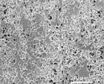
- FIG. 3 illustrates an SEM photograph of the surface having pitting corrosion-like recesses as an example of the electrode material made of the stainless steel material of the present invention.
- Each pitting corrosion-like recessed part is comprised by the pit (pitting corrosion) which has a circular shaped opening part.
- Circular shape refers to the diameter of the longest part in the outline of the opening when the surface of the steel sheet is viewed in a direction parallel to the plate thickness direction.
- the diameter is called “minor axis”, it means a shape having an aspect ratio represented by major axis / minor axis of 2 or less.
- the average opening diameter D can be determined as follows. That is, a straight line is drawn on an image obtained by viewing the surface of the steel plate in a direction parallel to the plate thickness direction, and from the pit where the outline of the pit intersects the straight line, an overall image of the shape of the opening appears in the outline Randomly select a total of 30 pits that can be estimated from the outline of the shape of the opening from the pit or its outline, measure the maximum diameter in the direction parallel to the straight line for each pit, and calculate the arithmetic average of those values The value obtained by doing this is defined as the average opening diameter D. A total of 30 pits may be selected by drawing a plurality of straight lines.
- a method for “selecting a total of 30 randomly” for example, a method of picking up all the pits in which the entire image of the opening shape appears along the straight line and the pits from which the entire image of the opening shape can be estimated You can pick up a total of 100 pits and select 30 pits randomly.
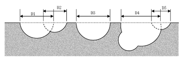
- FIG. 4 schematically shows the form of pitting pits appearing in a cross section parallel to the plate thickness direction.
- the opening distance (D1 to D5 in the figure) of each pit that appears in this cross section does not mean the above-mentioned “maximum diameter of each pit in the linear direction”.
- the present invention as a method for producing the above electrode material, in a ferric chloride aqueous solution having an Fe 3+ concentration of 1 to 50 g / L with respect to a stainless steel plate having the above composition and exhibiting a ferrite phase structure,
- the steel sheet is subjected to alternating electrolysis at 1 to 20 Hz with a current density during anode electrolysis of 1.0 to 10.0 kA / m 2 and a current density during cathode electrolysis of 0.1 to 3.0 kA / m 2.
- a method for producing an electrode material for a dye-sensitized solar cell in which a pitting corrosion-like recess having an average opening diameter D of 0.5 to 5 ⁇ m is formed on the surface at a ratio of 50% or more.
- the present invention provides an electrode of a dye-sensitized solar cell in which a catalyst layer or a photoelectric conversion layer is formed on the surface of a stainless steel plate having the pitting corrosion-like recess using the above electrode material as a base material.
- This electrode is an electrode on the side that does not need to transmit light.
- the electrode material of the dye-sensitized solar cell of the present invention When the electrode material of the dye-sensitized solar cell of the present invention is used, the following merits are obtained. (1) The conversion efficiency by the diffuse reflection effect of incident light can be improved by optimizing the concave area ratio and the aperture diameter. (2) By increasing the surface area due to the large number of recesses provided on the surface on the side on which the catalyst layer is formed, the amount of catalyst supported such as platinum can be reduced, and the cost can be reduced. (3) Since it is based on a stainless steel plate, it has higher conductivity than transparent conductive films such as ITO, FTO, and TO.
- the stainless steel of the substrate itself exhibits excellent corrosion resistance in the electrolyte solution used in the dye-sensitized solar cell, it is strong against the presence of defects and surface flaws in the catalyst layer.
- the thickness of the catalyst layer (the amount of catalyst material such as platinum) used can be minimized and the cost can be reduced.
- the stainless steel plate is the base, this electrode material itself has the function of a substrate and has higher strength than a conventional general glass substrate. Therefore, the present invention contributes to the spread of dye-sensitized solar cells.
- the figure which showed typically the structure of the conventional dye-sensitized solar cell (The type which has a photoelectric converting layer in the electrode by the side of incident light).
- the figure which showed typically the structure of the conventional dye-sensitized solar cell (The type by which the electrode of the incident light side is a counter electrode).
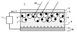
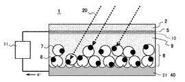
- FIG. 5 and 6 schematically show structural examples of a dye-sensitized solar cell using the electrode material of the present invention.
- FIG. 5 shows a conventional dye-sensitized solar cell of the type shown in FIG. 1, in which the substrate 4 and the counter electrode 5 are changed to a counter electrode 30 made of the electrode material of the present invention.
- the counter electrode 30 includes a stainless steel plate substrate 21 and a catalyst layer 10 provided on the surface thereof.
- FIG. 6 shows a conventional dye-sensitized solar cell of the type shown in FIG. 2, in which the substrate 4 and the photoelectrode 3 are replaced with a photoelectrode 40 made of the electrode material of the present invention.
- the photoelectrode 40 is made of a stainless steel plate substrate 21. 5 and 6, the surface of the stainless steel plate substrate 21 on the side of the electrolyte solution 9 is a roughened surface having pitting corrosion-like recesses. In the type of FIG. 5, the catalyst layer 10 is formed on this roughened surface.
- the cause is presumed as follows.
- the Ru dye used as the sensitizing dye has a property of being excited by light having a wavelength range of 350 to 800 nm which is a visible light region of sunlight.
- the amount of reflected light decreases because light is absorbed in the concave portions due to the standing wave resonance phenomenon. For this reason, the conversion efficiency decreases rather than in the case of a smooth electrode.
- a catalyst layer of platinum or the like is formed on the roughened surface of the stainless steel plate substrate as the counter electrode. Then, the catalytic substance is coated on the inner wall surface of the pitting corrosion-shaped recess formed on the surface of the stainless steel plate substrate, so that the opening diameter of the recess is smaller than that of the substrate on the electrode surface in which the catalyst is supported. Therefore, in order to reflect light having a wavelength of 350 to 800 nm, it is effective to set the average aperture diameter D to 0.5 ⁇ m or more, which is larger than 350 nm (0.35 ⁇ m), at the stage of the stainless steel plate of the substrate. . More preferably, it is 1 ⁇ m or more.
- the opening diameter of the concave portion increases, absorption due to standing wave resonance does not occur, and the above-described effect of improving the conversion efficiency can be obtained by sufficient diffuse reflected light.
- the opening diameter of the concave portion becomes excessively large, the effect of diffuse reflection itself is reduced.
- the average opening diameter D of the stainless steel plate is specified to be 5 ⁇ m or less.
- the area ratio of the recess on the steel plate surface is higher.
- the lower limit of the area ratio at which a practical effect is obtained is set to 50%.
- the substantial surface area (actual surface area) of the steel plate surface increases as the area ratio increases, the amount of platinum supported can be reduced at the same time.
- the surface having such a pitting corrosion-like recess has a surface roughness SRa in the range of 0.1 to 1.5 ⁇ m.
- SRa is more preferably 0.3 ⁇ m or more.
- the above-mentioned unique roughening form is a ferric chloride solution for a stainless steel plate having a non-roughened surface such as normal annealing / pickling finish, BA annealing finish, or skin pass rolling finish. It can obtain by performing the alternating electrolysis process in.
- the Fe 3+ concentration in the aqueous ferric chloride solution can be 1 to 50 g / L. A range of 10 to 40 g / L is more preferable.
- the current density during anodic electrolysis can be 1.0 to 10.0 kA / m 2 . If the anode current density is too low, pitting corrosion (pits) is not generated. If the anode current density is too high, the decomposition reaction of the electrolyte occurs, leading to a reduction in efficiency.
- the current density during cathode electrolysis can be set to 0.1 to 3.0 kA / m 2 . If the cathode current density is too low, hydrogen gas that promotes the formation of pitting corrosion is difficult to generate, and if it is too high, the pitting corrosion generated by excessive hydrogen generation tends to be lost.
- the cycle of alternating electrolysis affects the size of the generated pit, and in the present invention, it may be adjusted in the range of 1 to 20 Hz.
- the alternating electrolysis cycle is reduced, the energization time per cycle is increased, so that the size of pitting corrosion can be increased.
- the alternating electrolysis cycle is increased, the size of pitting corrosion can be reduced.
- the temperature of the electrolytic solution can be adjusted in the range of 30 to 70 ° C. What is necessary is just to adjust electrolysis time so that said roughening form may be obtained. Usually, optimum conditions can be found in the range of 10 to 300 seconds.
- “stainless steel” refers to steel having a Cr content of 10.5 mass% or more (number 4201 of JIS G0203). Even if a steel type having a particularly high corrosion resistance is not adopted, a catalyst layer having a sufficient film thickness can be formed by platinum coating or the like, so that it can be used as an electrode substrate of a dye-sensitized solar cell. However, when the platinum coating or the like is applied as thinly as possible, defects such as pinholes are likely to occur in the coating layer.
- the stainless steel type in order to construct a more reliable electrode, it has excellent durability with respect to the electrolyte solution of the dye-sensitized solar cell in the state of a bare stainless steel plate (the state where the catalyst layer is not formed). It is more preferable to use the stainless steel type to be used for the electrode substrate. As a result of various studies, the stainless steel type containing Cr in the range of 17 to 32% by mass and Mo in the range of 0.8 to 3% by mass has excellent durability against the electrolyte solution containing iodine ions of the dye-sensitized solar cell. It turns out that it exhibits sex.
- stainless steel chloride ion Cl - is to have a weak point in corrosion resistance to an aqueous solution containing, to improve its corrosion resistance the addition of increasing or Mo and Cr is to be effective.
- Cr 17% by mass or more
- Mo 1.75% by mass or more
- SUS316 which is a high corrosion resistance austenitic general-purpose steel grade
- Mo Content of 2 mass% or more is ensured.
- the inventors have found that when the Cr content in the stainless steel material is 17% by mass or more and the Mo content is 0.8% by mass or more, the iodine applied to the dye-sensitized solar cell. It has been found that excellent corrosion resistance that hardly dissolves in a fluoride-containing electrolyte solution is exhibited. As described above, even when the application is a daily hot water environment, in order to give the stainless steel sufficient corrosion resistance, it is necessary to add a relatively large amount of Mo, for example, 1.75% by mass or more. is there. Compared to this, it has been clarified that the corrosion resistance of the dye-sensitized solar cell in which iodide ions are present in the organic solvent to the electrolyte solution is remarkably improved from a smaller Mo addition range.
- the electrode material of the present invention it is more desirable to apply a stainless steel type containing Cr in the range of 17 to 32% by mass and Mo in the range of 0.8 to 3% by mass.
- a ferritic steel type that is less expensive than an austenitic steel type can be employed.
- it corresponds to existing steel types such as SUS434, SUS436L, SUS444, SUS445J1, SUS445J2, SUS447J1, and SUSXM27 specified in JIS G4305: 2005, in particular, Cr is 17 to 32% by mass
- Stainless steel having a composition containing Mo in the range of 0.8 to 3 mass% can be employed.
- the Cr content is less than 17% or the Mo content is less than 0.8%, it is excellent that the material hardly dissolves in the iodide-containing electrolyte solution applied to the dye-sensitized solar cell. It becomes difficult to stably obtain corrosion resistance.
- the Cr content is desirably 32% or less, and more preferably 30% or less.
- the Mo content is preferably 3% or less, and more preferably 2% or less.
- ferritic stainless steel as shown in the following (i) and (ii) can be employed.
- a more preferable content range of each selected element is Al: 0.03. -5%, Ti: 0.05-0.4%, Nb: 0.05-0.8%, Cu: 0.4-3%, Ni: 0.4-5%.
- the elements that can be mixed in the balance are P: 0.04 mass% or less, S: 0.03 mass% or less, V: 0.5 mass% or less, B: 0.1 mass% or less, Ca: 0.1 Mass% or less, Mg: 0.1 mass% or less, Y: 0.1 mass% or less, REM (rare earth element): 0.1 mass% or less.
- the balance can be limited to Fe and inevitable impurities.
- a “counter electrode” can be formed by providing a catalyst layer on the surface of the stainless steel plate on which the concave portion is formed.
- the catalyst substance include transition metals having high catalytic activity such as platinum and palladium, and organometallic complexes such as carbon black and porphyrin.
- known methods such as sputter coating and electroplating can be used. Sputter coating is suitable in terms of forming a platinum film that is as thin and uniform as possible.
- the catalyst layer can be formed by a method of applying and drying a paste mixed with a binder.
- This metal plate having a catalyst layer on the surface is used as a “counter electrode” of the dye-sensitized solar cell in such a state that the surface on the side where the catalyst layer is formed is in contact with the electrolyte solution.
- a photoelectric conversion layer is provided on the surface of the stainless steel plate on the side where the concave portion is formed.
- a battery cell of the type shown in FIG. 5 was constructed as follows and the conversion efficiency was examined.
- Stainless steel having the composition shown in Table 1 was melted, and a cold-rolled annealed steel sheet (No. 2D finish) having a thickness of 0.2 mm was manufactured by a general stainless steel sheet manufacturing process.
- the content of P which is an impurity, is suppressed to 0.04 mass% or less, and the content of S is suppressed to 0.002 mass% or less.
- the test piece cut out from the steel sheet was immersed in a ferric chloride aqueous solution with an Fe 3+ concentration of 30 g / L and 50 ° C., the anode electrolysis current density was 3 kA / m 2 , and the cathode electrolysis current density was 0.3 kA / m 2.
- roughening treatment was carried out at various alternating cycles and electrolysis times. The roughened surface was observed with a scanning electron microscope (SEM), and the average opening diameter D of the pitting pits and the area ratio of the pitting pits were measured by the method described above.
- the three-dimensional surface profile of a 50 micrometer x 50 micrometer rectangular area was measured using the scanning confocal laser microscope (Olympus Co., Ltd. product; OLS1200).
- the three-dimensional average surface roughness SRa calculated from the pull file data was determined.
- the roughened surface was coated with platinum at an output of 50 W for a predetermined time by sputter coating to form a platinum catalyst layer, and a test material for an electrode was obtained.
- Each processing condition and roughening form are shown in Table 2.
- a PEN film with an ITO film having a size of 20 mm ⁇ 20 mm (Peccell Technologies, Inc .; PECF-IP) was prepared. Titanium oxide nanopaste (manufactured by Pexel Technologies, Inc .; PECC-01-06) was applied to a 5 mm ⁇ 5 mm region on the film surface by a doctor blade method and dried. The dried film was immersed in a liquid in which N719-based ruthenium complex dye (PECD-07 manufactured by the same company) was dispersed in an acetonitrile-containing solvent to adsorb the dye, thereby producing a photoelectrode.
- PECD-07 N719-based ruthenium complex dye
- An ionomer resin film (trade name: High Milan) having a size of 20 mm ⁇ 20 mm and a thickness of 50 ⁇ m was prepared. A 5 mm ⁇ 5 mm region is cut out in the center of the film, and a hole is formed, and this is used as a spacer, and heat fusion is carried out on the surface of the catalyst layer of the above-described test material (catalyst layer formed on a roughened stainless steel plate substrate). Thus, a counter electrode with a spacer was produced.
- Each terminal of the IV characteristic measuring device (Peccell Technologies; PECK2400-N) is connected to each electrode of the battery cell, and 100 mW / cm with a solar simulator (Peccell Technologies; PEC-L11). The conversion efficiency when irradiating cm 2 pseudo sunlight was measured.
- the conversion efficiency ratio refers to the conversion efficiency when using a counter electrode in which platinum is sputter coated for 90 minutes on the Nesa glass (ITO (tin oxide) transparent conductive film deposited on a glass substrate) described in the reference column.
- the ratio value is defined as
- the conversion efficiency ratio exceeds 100 for all of the examples of the present invention, although the platinum sputtering time is as short as 10 min, which is higher than when 90 minutes sputtered nesa glass is used as the counter electrode. The value is shown and no deterioration over time is observed. Since the conversion efficiency ratio is as low as 90 for nesa glass of 10 min sputtering, the amount of platinum used can be reduced by using the electrode material made of the stainless steel plate of the present invention. Moreover, it is considered that the conversion efficiency is higher than that of Comparative Example No. 11 without electrolysis because of the diffuse reflection effect due to the surface shape.
- Comparative Example No. 6 had a small effect of improving the conversion efficiency due to the large average opening diameter D of the pitting corrosion-like recesses.
- No. 7 had a lower conversion efficiency than that without electrolysis (No. 11) because the average opening diameter D was too small and the surface roughness SRa was too small.
- the effect of improving the conversion efficiency was small because the area ratio of the pitting corrosion-like recesses was too low.
- No. 9 and No. 10 are inferior in corrosion resistance to the electrolytic solution due to the low Mo content or further Cr content of the stainless steel, and the conversion efficiency after 1000 hours is significantly reduced. This is presumed to be caused by the dissolution of steel components such as Fe and Cr into the electrolyte solution through pinholes in the platinum coating film. This problem can be eliminated by sufficiently increasing the thickness of the platinum coating.
- a battery cell of the type shown in FIG. 6 was constructed as follows, and the conversion efficiency was examined.
- the substrate of the photoelectrode the same roughened stainless steel plate as used in the counter electrode in Example 1 and the stainless steel plate that has not been subjected to the roughening treatment (both have no platinum catalyst layer formed) Prepared.
- a counter electrode material a PEN film with an ITO film coated with platinum for 1 min by sputtering was prepared.
- a small battery cell was produced in the same procedure as in Example 1, and the conversion efficiency was measured.
- a photoelectrode was produced using the stainless steel substrate instead of the PEN film with an ITO film. Light irradiation was performed from the counter electrode side.
- the conversion efficiency ratio is defined as the value of the ratio when the conversion efficiency when the PEN film with an ITO film is used for the photoelectrode described in the reference column is 100.
Landscapes
- Engineering & Computer Science (AREA)
- Power Engineering (AREA)
- Microelectronics & Electronic Packaging (AREA)
- Hybrid Cells (AREA)
- Photovoltaic Devices (AREA)
Abstract
色素増感型太陽電池において、良好な電気伝導および高い変換効率が確保される安価な電極材料ならびにそれを用いた電極を提供する。 表面に面積率50%以上の割合で平均開口径D:0.5~5μmの孔食状凹部を有するステンレス鋼板からなる色素増感型太陽電池の電極材料。そのステンレス鋼板はCrを17~32質量%、Moを0.8~3質量%の範囲で含有する鋼種を採用することが好適である。例えば、JIS G4305:2005に規定されるフェライト系鋼種において、Crを17~32質量%、Moを0.8~3質量%の範囲で含有するものを選択することができる。この電極材料を基材として、その孔食状凹部を有するステンレス鋼板表面に触媒層または光電変換層を形成することにより、色素増感型太陽電池の電極が構成される。
Description
本発明は、色素増感型太陽電池の電極を構成する材料であって、受光面と反対側に設けられる透明性が要求されない「対極」や「光電極」に使用する電極材料およびその製造方法、並びにその電極材料を用いた色素増感型太陽電池の電極に関する。
太陽電池は現在、シリコンを光電変換素子に用いたものが主流となっているが、これに替わるより経済的な次世代太陽電池として「色素増感型太陽電池」の実用化が研究されている。
図1、図2に、従来の色素増感型太陽電池の構成を模式的に示す。図1は入射光側の電極に光電変換層を有するタイプ、図2は入射光側の電極が溶液中のイオンに電子を渡すための「対極」になっているタイプである。
図1のタイプでは、透明基板2の表面に形成された光電極3と、基板4の表面に形成された対極5が向かい合って太陽電池1を構成している。このタイプの光電極3は光を透過する必要があることから、通常、ITO(インジウム-錫酸化物)、FTO(フッ素ドープ酸化錫)、TO(酸化錫)等の透明導電膜で構成される。透明基板2にはガラスなどが使用される。光電極3の表面には光電変換層6が形成されている。光電変換層6は比表面積の大きいTiO2粒子7からなる多孔質層であり、TiO2粒子7の表面にはRu色素8が担持されている。光電変換層6と対極5の間にはヨウ化物イオンを含む電解質溶液9が満たされている。対極側は、基板4上に透明導電膜からなる対極5が設けられ、その上に白金等の貴金属からなる触媒層10が形成されている。太陽電池1の外部には光電極3と対極5の間に負荷11が導線で結ばれ、回路を形成している。
入射光20がRu色素8に到達すると、Ru色素8は光を吸収して励起され、その電子がTiO2粒子7へと注入される。励起状態になったRu色素8は電解質溶液9のヨウ化物イオンI-から電子を受け取り、基底状態に戻る。I-は酸化されてI3
-となり、対極5へ拡散し、対極5から電子を受け取ってI-に戻る。これにより、電子はRu色素8→TiO2粒子7→光電極3→負荷11→対極5→触媒層10→電解質溶液9→Ru色素8の経路で移動する。その結果、負荷11を作動させる電流が発生する。
図2のタイプでは、対極5が光を透過するITO、FTO、TO等の透明導電膜で構成され、他方の電極である光電極3の表面に光電変換層6が形成されている。この場合の光電極3は必ずしも透明である必要はない。電流が発生する原理は、基本的に図1のタイプと同じである。
特許文献1~6には、色素増感型太陽電池の電極に白金などの耐食性金属からなる導電膜を使用することが記載されている。また、対極を厚さ1mmの白金板で構成する例もある(特許文献6)。
現状の色素増感型太陽電池の変換効率は、シリコン太陽電池と比較して低く、高効率化を図ることが大きな課題のひとつとなっている。色素増感型太陽電池の高効率化を狙った技術として、例えば特許文献1には電極対を複数積層し、光の入射側から最も離れた対極を反射性の電極層とすることにより、変換効率を向上させるとともに単位面積当たりの電力供給量を増大させる技術が開示されている。すなわち入射光を複数の電極層において吸収させ、さらに反射性対極で反射した反射光を逆経路において吸収させることで、高効率化を図っている。
しかし、特許文献1の技術では反射性の電極層として電解質溶液に対する耐食性に優れる白金、金、銀、チタンなどの高価な金属あるいはそれらの合金が使用されるため材料コストが非常に高くなる欠点がある。特に白金は導電性が高くかつ触媒作用を呈することから対極材料として非常に有効であるが、極めて高価であるから、その使用量を必要最小限に低減することが強く望まれている。
また、特許文献3には樹脂製対極基板表面に1~1000nmスケールの凹凸構造を有するチタン、タンタルなどの耐食金属材料膜をスパッタリング法により形成し、その表面に白金膜を形成する方法が開示されている。この方法によれば、対極と電解質溶液との接触面積が大きくなるので、表面抵抗が低減され、白金の膜厚を薄くしてもトータルでの電気抵抗の低下は緩和される。しかし、この方法によっても樹脂製基板を使用している以上、対極での通電は白金膜のみによって賄う必要があり、十分な導電性を確保するためには相当量の白金が依然として必要であり、より低コスト化が図れる構造が求められている。
このように、色素増感型太陽電池の電極には白金等の貴金属が相当量使用されているのが現状であり、高価な貴金属を使用することによるコストの増大を伴っている。白金や、カーボンブラックその他の材料で「膜」を形成するタイプの電極では、電極内での電気伝導性についても改善の余地がある。
本発明はこのような現状に鑑み、色素増感型太陽電池のヨウ化物イオンを含む電解質溶液中で優れた耐食性を示す金属材料で構成され、良好な電気伝導および高い変換効率が確保される安価な電極材料ならびにそれを用いた電極を提供しようというものである。
上記目的を達成するために、発明者らは色素増感型太陽電池の光を透過させる必要のない側に用いる電極基板として種々の金属材料について検討を重ねた結果、表面に適正な大きさの半球状凹部を多数設けたステンレス鋼板が使用できることを見出した。特に適量のMoを含有する高Crフェライト系ステンレス鋼は電解質溶液に対する耐食性が良好であり、耐久性の高い色素増感型太陽電池を構築する上で有用である。
すなわち本発明では、表面に面積率50%以上の割合で平均開口径D:0.5~5μmの孔食状凹部を有するステンレス鋼板からなる色素増感型太陽電池の電極材料が提供される。その孔食状凹部を有する表面は、例えば面粗さSRaが0.1~1.5μm、好ましくは0.3~1.5μmである。このステンレス鋼板はCrを17~32質量%、Moを0.8~3質量%の範囲で含有する鋼種を採用することが好適である。例えば、JIS G4305:2005に規定されるフェライト系鋼種において、Crを17~32質量%、Moを0.8~3質量%の範囲で含有するものを選択することができる。
より具体的なステンレス鋼板としては、質量%で、C:0.15%以下、Si:1.2%以下、Mn:1.2%以下、Cr:17~32%、Mo:0.8~3%、N:0.025%以下、残部実質的にFeの組成を有し、フェライト相組織を呈しするものが挙げられるまた、上記元素の他にAl:5%以下、Ti:1%以下、Nb:1%以下、Cu:3%以下、Ni:5%以下の1種以上を含有するものを採用しても構わない。
ここで、「残部実質的にFe」とは、本発明の効果を阻害しない限り、上記以外の元素の混入が許容されることを意味し、「残部がFeおよび不可避的不純物からなる」場合が含まれる。「フェライト相組織」は、析出物や介在物を除いた金属マトリクスがフェライト相からなる金属組織をいう。「面積率50%以上の割合で」とは、鋼板表面を板厚方向に対して平行方向に見た観察領域の投影面積に占める、孔食状凹部が形成されている領域(すなわちピット未発生部分を除いた領域)の投影面積の割合が50%以上であることをいう。面粗さSRaは、表面粗さ曲線をサインカーブで近似した際の中心面(基準面)における平均粗さを意味し、触針式三次元表面粗さ計やレーザ顕微鏡などを用いて得た各点の高さを測定し、これらの測定値を三次元表面粗さ解析することにより得られる値である。その測定領域は例えば1辺が40μm以上の矩形領域(例えば50μm×50μm)とすればよい。
図3に、本発明のステンレス鋼材からなる電極材料の一例について、孔食状凹部を有する表面のSEM写真を例示する。個々の孔食状凹部は、円形状の開口部を有するピット(孔食)によって構成されている。円形状とは、鋼板表面を板厚方向に対して平行方向に見た場合に、開口部の輪郭において最も長い部分の径を「長径」と呼び、その長径に対して直角方向の最も長い部分の径を「短径」と呼ぶとき、長径/短径で表されるアスペクト比が2以下の形状をいう。ピット開口部の輪郭によって開口部の形状の全体像が明瞭にわかるピットも見られるが、複数のピット同士がつながって凹部を形成している部分では、全体像が輪郭に現れていないピットも存在する。しかし、そのようなピットでも、輪郭から全体像(すなわち円形状の開口部の形状)を比較的精度良く推定することができるピットも数多くある。
平均開口径Dは以下のようにして定めることができる。すなわち、鋼板表面を板厚方向に対して平行方向に見た画像上に直線を引き、ピットの輪郭がその直線と交わるピットの中から、その輪郭に開口部の形状の全体像が現れているピット、またはその輪郭から開口部の形状の全体像が推定可能なピットを無作為に合計30個選び、各ピットについて前記直線に対して平行方向の最大径を測定し、それらの値を算術平均することによって求まる値を平均開口径Dとする。複数本の直線を引くことによって合計30個のピットを選択しても構わない。「無作為に合計30個選ぶ」ための方法としては、例えば前記直線に沿って開口部の形状の全体像が現れているピットおよび開口部の形状の全体像が推定可能なピットを全て拾い上げる手法で合計100個のピットを拾い上げ、その中からランダムに30個のピットを選ぶ方法が採用できる。
図4に、板厚方向に平行な断面に現れる孔食状ピットの形態を模式的に表す。この断面内に現れる各ピットの開口部距離(図中D1~D5)は、前述した「各ピットの前記直線方向における最大径」を意味するわけではない。
また本発明では、上記の電極材料の製造方法として、上記の組成を有し、フェライト相組織を呈するステンレス鋼板に対して、Fe3+濃度1~50g/Lの塩化第二鉄水溶液中で、アノード電解時の電流密度を1.0~10.0kA/m2、カソード電解時の電流密度を0.1~3.0kA/m2とした1~20Hzの交番電解を施すことにより、当該鋼板表面に面積率50%以上の割合で平均開口径D:0.5~5μmの孔食状凹部を形成する色素増感型太陽電池の電極材料の製造方法が提供される。
さらに本発明では、上記の電極材料を基材として、その孔食状凹部を有するステンレス鋼板表面に触媒層または光電変換層を形成した色素増感型太陽電池の電極が提供される。この電極は光を透過させる必要のない側の電極である。
本発明の色素増感型太陽電池の電極材料を用いると以下のようなメリットが得られる。
(1)凹部面積率および開口径の最適化により入射光の拡散反射効果による変換効率の向上が図れる。
(2)触媒層を形成する側の表面に設けられた多数の凹部による表面積の増大により、白金等の触媒担持量を低減でき、低コスト化が図れる。
(3)ステンレス鋼板をベースにしているので、ITO、FTO、TO等の透明導電膜と比べ導電性が高い。
(4)基板のステンレス鋼は、それ自体が色素増感型太陽電池に使用される電解液中で優れた耐食性を示すものであるため、触媒層の欠陥・表面疵の存在に対して強い。
(5)触媒層の欠陥・表面疵の存在に対して強いことから、触媒層の厚さ(白金等の触媒物質の使用量)を必要最小限にすることができ、コストが低減される。
(6)ステンレス鋼板がベースであるため、この電極材料自体で基板の機能を有し、かつ従来一般的なガラス基板よりも強度が高い。
したがって、本発明は色素増感型太陽電池の普及に寄与するものである。
(1)凹部面積率および開口径の最適化により入射光の拡散反射効果による変換効率の向上が図れる。
(2)触媒層を形成する側の表面に設けられた多数の凹部による表面積の増大により、白金等の触媒担持量を低減でき、低コスト化が図れる。
(3)ステンレス鋼板をベースにしているので、ITO、FTO、TO等の透明導電膜と比べ導電性が高い。
(4)基板のステンレス鋼は、それ自体が色素増感型太陽電池に使用される電解液中で優れた耐食性を示すものであるため、触媒層の欠陥・表面疵の存在に対して強い。
(5)触媒層の欠陥・表面疵の存在に対して強いことから、触媒層の厚さ(白金等の触媒物質の使用量)を必要最小限にすることができ、コストが低減される。
(6)ステンレス鋼板がベースであるため、この電極材料自体で基板の機能を有し、かつ従来一般的なガラス基板よりも強度が高い。
したがって、本発明は色素増感型太陽電池の普及に寄与するものである。
図5、図6に、本発明の電極材料を使用した色素増感型太陽電池の構成例を模式的に示す。図5は、図1に示されるタイプの従来の色素増感型太陽電池において、基板4と対極5を、本発明の電極材料からなる対極30に変えたものである。この対極30は、ステンレス鋼板基板21と、その表面に設けられた触媒層10からなる。図6は、図2に示されるタイプの従来の色素増感型太陽電池において、基板4と光電極3を、本発明の電極材からなる光電極40に変えたものである。この光電極40は、ステンレス鋼板基板21からなる。図5、図6いずれのタイプでも、ステンレス鋼板基板21の電解質溶液9側の表面は、孔食状凹部を有する粗面化表面である。図5のタイプでは、この粗面化表面の上に触媒層10が形成されている。
〔粗面化形態〕
発明者らの研究によれば、光を透過させる必要のない側の電極材料として表面に多数の孔食状凹部を形成したステンレス鋼板を使用した色素増感型太陽電池では、平滑面の電極材料の場合と比較して変換効率が高くなることを見出した。そして、変換効率に対しては、触媒担持量よりも、凹部の開口径および凹部の面積率(すなわち粗面化形態)の方がはるかに大きい影響を及ぼすことを見出した。
発明者らの研究によれば、光を透過させる必要のない側の電極材料として表面に多数の孔食状凹部を形成したステンレス鋼板を使用した色素増感型太陽電池では、平滑面の電極材料の場合と比較して変換効率が高くなることを見出した。そして、変換効率に対しては、触媒担持量よりも、凹部の開口径および凹部の面積率(すなわち粗面化形態)の方がはるかに大きい影響を及ぼすことを見出した。
詳細な検討の結果、前述の平均開口径Dが0.5~5μmである場合に変換効率の向上効果が大きいことがわかった。
そのメカニズムについては未だ未解明の部分も多いが、次のようなことが考えられる。透明電極側から入射した光はその一部が色素に吸収され、残りは反対側のステンレス鋼板基板を用いた電極へ達する。この時、ステンレス鋼板に形成された多数の凹部表面で光はあらゆる方向へ向けて拡散反射されるため、その反射光は、正反射だけの場合に比べると、より効率よく色素に吸収されると考えられる。しかしながら、実際には平均開口径Dが0.5μm未満の非常に微細な凹部が形成されている場合、その変換効率は平滑面の場合と比較して逆に低下するという現象が起きることがわかった。
その原因は次のように推察される。増感色素として使用されるRu色素は太陽光の可視光領域である350~800nmの波長範囲の光によって励起される性質がある。ところが、入射光を反射する電極の表面に、この波長より小さい開口の凹部が多数存在すると、定常波共鳴現象に起因して凹部内において光が吸収されるため反射光量が減少してしまう。このため変換効率は平滑な電極の場合よりもむしろ低下する。
図5に示したように、対極となるステンレス鋼板基板の粗面化表面上には白金などの触媒層が形成される。そうすると、ステンレス鋼板基板の表面に形成されている孔食状凹部の内部の壁面に触媒物質がコーティングされるので、触媒を担持させた状態の電極表面においては凹部の開口径が基板より小さくなる。このため、波長が350~800nmの光を反射させるためには、基板のステンレス鋼板の段階において、平均開口径Dを350nm(0.35μm)よりも大きい0.5μm以上としておくことが有効となる。1μm以上とすることがより好ましい。
一方、凹部の開口径が大きくなると、定常波共鳴による吸収は起きなくなり、十分な拡散反射光により上述した変換効率の向上効果が得られる。ところが、凹部の開口径が過剰に大きくなると、拡散反射自体の効果が減少してしまう。種々検討の結果、基板のステンレス鋼板の段階での平均開口径Dが5μmを超えて大きくなると、実質的な変換効率の向上効果を得ることが難しくなる。したがって、ステンレス鋼板の平均開口径Dは5μm以下に規定される。
また、上記適正寸法の凹部による拡散反射の効果を得るためには、鋼板表面に占める凹部の面積率が高いほど望ましい。本発明では実用的な効果が得られる面積率としてその下限を50%とした。また、この面積率が高いほど鋼板表面の実質的な表面積(実表面積)が増加することから、白金担持量の低減も同時に可能となる。
このような孔食状凹部を有する表面としては、面粗さSRaが0.1~1.5μmの範囲にあることが好ましい。SRaを0.1μm以上とすることにより、拡散反射の効果をより一層効果的に得ることができる。SRaは0.3μm以上であることがより好ましい。ただし、電解粗面化によってSRaが1.5μm以上の粗面化表面を得ることは容易ではない。
〔交番電解処理〕
以上のような特異な粗面化形態は、通常の焼鈍・酸洗仕上げ、BA焼鈍仕上げ、あるいはスキンパス圧延仕上げなど、粗面化していない表面性状のステンレス鋼板に対して、塩化第二鉄溶液中での交番電解処理を施すことによって得ることができる。
以上のような特異な粗面化形態は、通常の焼鈍・酸洗仕上げ、BA焼鈍仕上げ、あるいはスキンパス圧延仕上げなど、粗面化していない表面性状のステンレス鋼板に対して、塩化第二鉄溶液中での交番電解処理を施すことによって得ることができる。
塩化第二鉄水溶液中のFe3+濃度は1~50g/Lとすることができる。10~40g/Lの範囲とすることがより好ましい。
アノード電解時の電流密度は1.0~10.0kA/m2とすることができる。アノード電流密度が低すぎると孔食(ピット)が生成せず、高すぎると電解液の分解反応が起きるため効率低下を招く。カソード電解時の電流密度は0.1~3.0kA/m2とすることができる。カソード電流密度が低すぎると孔食形成を促進する水素ガスが発生しにくくなり、高すぎると過剰の水素発生により生成した孔食の消失を招きやすい。また、交番電解のサイクルは生成するピットの大きさに影響し、本発明では1~20Hzの範囲で調整すればよい。交番電解サイクルを小さくすると1サイクル当りの通電時間が長くなるので孔食のサイズを増大させることができ、逆に交番電解サイクルが大きくすると孔食のサイズを小さくすることができる。電解液の温度は30~70℃の範囲で調整することができる。電解時間は上記の粗面化形態が得られるように調整すればよい。通常10~300秒の範囲で最適な条件を見出すことができる。
〔基材のステンレス鋼〕
本願において「ステンレス鋼」は、Cr含有量が10.5質量%以上の鋼をいう(JIS G0203の番号4201)。特段に高耐食性を有する鋼種を採用しなくても、白金コーティング等により十分な膜厚の触媒層を形成させることにより、色素増感型太陽電池の電極基材として使用することが可能になる。ただし、白金コーティング等をできるだけ薄く施す場合には、そのコーティング層にピンホール等の欠陥が生じやすくなる。したがって、より信頼性の高い電極を構築するためには、裸のステンレス鋼板の状態(触媒層を形成していない状態)で、色素増感型太陽電池の電解質溶液に対して優れた耐久性を呈するステンレス鋼種を電極基材に使用することがより好ましい。種々検討の結果、Crを17~32質量%、Moを0.8~3質量%の範囲で含有するステンレス鋼種は、色素増感型太陽電池のヨウ素イオンを含む電解質溶液に対して優れた耐久性を呈することがわかった。
本願において「ステンレス鋼」は、Cr含有量が10.5質量%以上の鋼をいう(JIS G0203の番号4201)。特段に高耐食性を有する鋼種を採用しなくても、白金コーティング等により十分な膜厚の触媒層を形成させることにより、色素増感型太陽電池の電極基材として使用することが可能になる。ただし、白金コーティング等をできるだけ薄く施す場合には、そのコーティング層にピンホール等の欠陥が生じやすくなる。したがって、より信頼性の高い電極を構築するためには、裸のステンレス鋼板の状態(触媒層を形成していない状態)で、色素増感型太陽電池の電解質溶液に対して優れた耐久性を呈するステンレス鋼種を電極基材に使用することがより好ましい。種々検討の結果、Crを17~32質量%、Moを0.8~3質量%の範囲で含有するステンレス鋼種は、色素増感型太陽電池のヨウ素イオンを含む電解質溶液に対して優れた耐久性を呈することがわかった。
一般にステンレス鋼は塩化物イオンCl-を含む水溶液に対する耐食性において弱点を有するとされ、その耐食性を改善するにはCrの増量やMoの添加が有効であるとされる。例えば温水器に適したフェライト系のSUS444ではCr:17質量%以上、Mo:1.75質量%以上の含有量が確保されており、高耐食性オーステナイト系汎用鋼種であるSUS316でもCr:16質量%以上、Mo:2質量%以上の含有量が確保されている。しかし、ヨウ化物イオンに対するステンレス鋼の耐食性については意外にも報告が少ない。その理由として、ヨウ化物イオンに曝されるような環境は自然界や日常においてほとんど存在しないことが挙げられる。特に、溶媒が水ではなく、有機物質である場合のヨウ化物イオン含有電解質溶液に関し、ステンレス鋼の組成と耐食性の関係はほとんど把握されていない。裸の状態では汎用鋼種であるSUS430やSUS304が当該電解質溶液に対して激しく腐食することはわかっており、色素増感型太陽電池の電極用途へのステンレス鋼材料の適用は敬遠されてきた。このことが、詳細な検討を試みる動機付けをそぐ要因となっていた。
発明者らは詳細な検討の結果、ステンレス鋼材料においてCr含有量を17質量%以上とし、かつMo含有量を0.8質量%以上としたとき、色素増感型太陽電池に適用されるヨウ化物含有電解質溶液中での溶解がほとんど生じない優れた耐食性が発現することを見出した。上記のように、用途が日常の温水環境である場合でも、それに十分耐え得る耐食性をステンレス鋼に付与するには、例えば1.75質量%以上という比較的多量のMoを添加する措置が必要である。これに比べると、有機溶媒中にヨウ化物イオンが存在する色素増感型太陽電池の電解質溶液に対する耐食性は、より少ないMo添加量範囲から顕著に改善されることが明らかになった。
したがって、本発明の電極材料としては、Crを17~32質量%、Moを0.8~3質量%の範囲で含有するステンレス鋼種を適用することがより望ましい。特に本発明では、オーステナイト系鋼種に比べ安価なフェライト系鋼種を採用することができる。そのような鋼として、具体的には、例えばJIS G4305:2005に規定されるSUS434、SUS436L、SUS444、SUS445J1、SUS445J2、SUS447J1、SUSXM27等の既存鋼種に相当し、特にCrを17~32質量%、Moを0.8~3質量%の範囲で含有する組成のステンレス鋼を採用することができる。
Cr含有量が17%未満またはMo含有量が0.8%未満だと、色素増感型太陽電池に適用されるヨウ化物含有電解質溶液中において、当該材料の溶解がほとんど生じないような優れた耐食性を安定して得ることが難しくなる。より信頼性を向上させるには、Crは18%以上、Moは1%以上含有させることが好ましい。ただし、CrやMoの含有量が過剰に多くなると製造性を害する等の弊害が顕著になる。このため、Cr含有量は32%以下とすることが望ましく、30%以下が一層好ましい。またMo含有量は3%以下とすることが望ましく、2%以下が一層好ましい。
より具体的には、以下の(i)(ii)に示すようなフェライト系ステンレス鋼を採用することができる。
(i)質量%で、C:0.15%以下、Si:1.2%以下、Mn:1.2%以下、Cr:17~32%、Mo:0.8~3%、N:0.025%以下、残部実質的にFe
(ii)質量%で、C:0.15%以下、Si:1.2%以下、Mn:1.2%以下、Cr:17~32%、Mo:0.8~3%、N:0.025%以下であり、さらに、Al:5%以下、Ti:1%以下、Nb:1%以下、Cu:3%以下、Ni:5%以下の1種以上を含有し、残部実質的にFe
(i)質量%で、C:0.15%以下、Si:1.2%以下、Mn:1.2%以下、Cr:17~32%、Mo:0.8~3%、N:0.025%以下、残部実質的にFe
(ii)質量%で、C:0.15%以下、Si:1.2%以下、Mn:1.2%以下、Cr:17~32%、Mo:0.8~3%、N:0.025%以下であり、さらに、Al:5%以下、Ti:1%以下、Nb:1%以下、Cu:3%以下、Ni:5%以下の1種以上を含有し、残部実質的にFe
上記(ii)の場合において、各選択元素のより好ましい含有量範囲は、Al:0.03
~5%、Ti:0.05~0.4%、Nb:0.05~0.8%、Cu:0.4~3%、Ni:0.4~5%である。
~5%、Ti:0.05~0.4%、Nb:0.05~0.8%、Cu:0.4~3%、Ni:0.4~5%である。
残部に混入可能な元素としては、P:0.04質量%以下、S:0.03質量%以下、V:0.5質量%以下、B:0.1質量%以下、Ca:0.1質量%以下、Mg:0.1質量%以下、Y:0.1質量%以下、REM(希土類元素):0.1質量%以下などである。
残部はFeおよび不可避的不純物に制限することもできる。
残部はFeおよび不可避的不純物に制限することもできる。
〔電極〕
ステンレス鋼板の上記凹部が形成された側の表面に触媒層を設けることにより「対極」とすることができる。触媒物質としては、白金、パラジウムなどの触媒活性の高い遷移金属、カーボンブラック、ポルフィリンなどの有機金属錯体が挙げられる。白金を用いた触媒層を形成させる手法としては、スパッタコーティング、電気めっきなど、公知の手法が利用できるが、できるだけ薄く均一な白金膜を形成させるという点ではスパッタコーティングが適している。カーボンブラックの場合にはバインダーと混合したペーストを塗布、乾燥する方法などによって触媒層を形成できる。表面に触媒層を有するこの金属板は、色素増感型太陽電池の「対極」として、触媒層を形成した側の表面が電解質溶液に接触するような状態で使用される。一方、「光電極」とする場合にはステンレス鋼板の上記凹部が形成された側の表面に光電変換層を設ける。
ステンレス鋼板の上記凹部が形成された側の表面に触媒層を設けることにより「対極」とすることができる。触媒物質としては、白金、パラジウムなどの触媒活性の高い遷移金属、カーボンブラック、ポルフィリンなどの有機金属錯体が挙げられる。白金を用いた触媒層を形成させる手法としては、スパッタコーティング、電気めっきなど、公知の手法が利用できるが、できるだけ薄く均一な白金膜を形成させるという点ではスパッタコーティングが適している。カーボンブラックの場合にはバインダーと混合したペーストを塗布、乾燥する方法などによって触媒層を形成できる。表面に触媒層を有するこの金属板は、色素増感型太陽電池の「対極」として、触媒層を形成した側の表面が電解質溶液に接触するような状態で使用される。一方、「光電極」とする場合にはステンレス鋼板の上記凹部が形成された側の表面に光電変換層を設ける。
図5に示すタイプの電池セルを以下のようにして構成し、変換効率を調べた。
表1に示す組成のステンレス鋼を溶製し、一般的なステンレス鋼板製造工程により板厚0.2mmの冷延焼鈍鋼板(No.2D仕上)を製造した。各鋼とも不純物であるPの含有量は0.04質量%以下、Sの含有量は0.002質量%以下に抑えられている。
表1に示す組成のステンレス鋼を溶製し、一般的なステンレス鋼板製造工程により板厚0.2mmの冷延焼鈍鋼板(No.2D仕上)を製造した。各鋼とも不純物であるPの含有量は0.04質量%以下、Sの含有量は0.002質量%以下に抑えられている。

上記鋼板から切り出した試験片をFe3+濃度30g/L、50℃の塩化第二鉄水溶液中に浸漬し、アノード電解電流密度を3kA/m2、カソード電解電流密度を0.3kA/m2とし、種々の交番サイクルおよび電解時間で粗面化処理を施した。粗面化処理した表面を走査型電子顕微鏡(SEM)で観察し、前述の手法により、孔食状凹部の平均開口径Dおよび孔食状凹部の面積率を測定した。また、粗面化表面について、走査型共焦点レーザー顕微鏡(オリンパス株式会社製;OLS1200)を用いて、50μm×50μmの矩形領域の三次元表面プロファイルを測定した。そのプルファイルのデータから算出される三次元平均表面粗さSRaを求めた。
粗面化表面にスパッタコーティングにより出力50Wで白金を所定の時間コーティングして、白金の触媒層を形成し、電極用の供試材を得た。
各処理条件ならびに粗面化形態を表2中に示してある。
各処理条件ならびに粗面化形態を表2中に示してある。
次に、白金の触媒層を有する上記供試材を「対極」として用いて小型の電池セルを作製し、変換効率を測定した。実験は以下の手順で行った。
[1]20mm×20mmの大きさのITO膜付きPENフィルム(ペクセルテクノロジーズ社製;PECF-IP)を用意した。そのフィルム表面の5mm×5mmの領域に酸化チタンナノペースト(ペクセルテクノロジーズ社製;PECC-01-06)をドクターブレード法にて塗布し、乾燥させた。N719系ルテニウム錯体色素(同社製PECD-07)をアセトニトリル含有溶媒に分散させた液中に、前記乾燥後のフィルムを浸漬して色素を吸着させ、光電極を作製した。
[2]20mm×20mm、厚さ50μmのアイオノマー樹脂フィルム(商品名;ハイミラン)を用意した。このフィルムの中央に5mm×5mmの領域を切り抜いて穴をあけ、これをスペーサーとして、上記供試材(粗面化ステンレス鋼板基板に触媒層形成したもの)の触媒層の表面上に加熱融着し、スペーサー付き対極を作製した。
[3]光電極とスペーサー付き対極とを、それぞれの5mm×5mmの領域どうしが一致するように重ね合わせ、その5mm×5mmの領域の間の隙間に電解質溶液(ペクセルテクノロジーズ社製;PECE-K01)を注入し、その後、クリップで固定して電池セルを得た。
[4]電池セルの各電極にI-V特性計測装置(ペクセルテクノロジーズ社製;PECK2400-N)の各端子を接続し、ソーラーシミュレータ(ペクセルテクノロジーズ社製;PEC-L11)にて100mW/cm2の擬似太陽光を照射した時の変換効率を測定した。
[5]電池セル作製直後の変換効率を測定した後、セルをアルゴンガスパージしたグローブボックス内で室温にて1000h保管した。その後再度[4]の方法で変換効率を測定した。
結果を表2に示す。ここで変換効率比とは、参考欄に記載したネサガラス(ITO(酸化錫)の透明導電膜をガラス基板上に蒸着したもの)に白金を90minスパッタコーティングした対極を使用したときの変換効率を100とした場合の比の値と定義する。
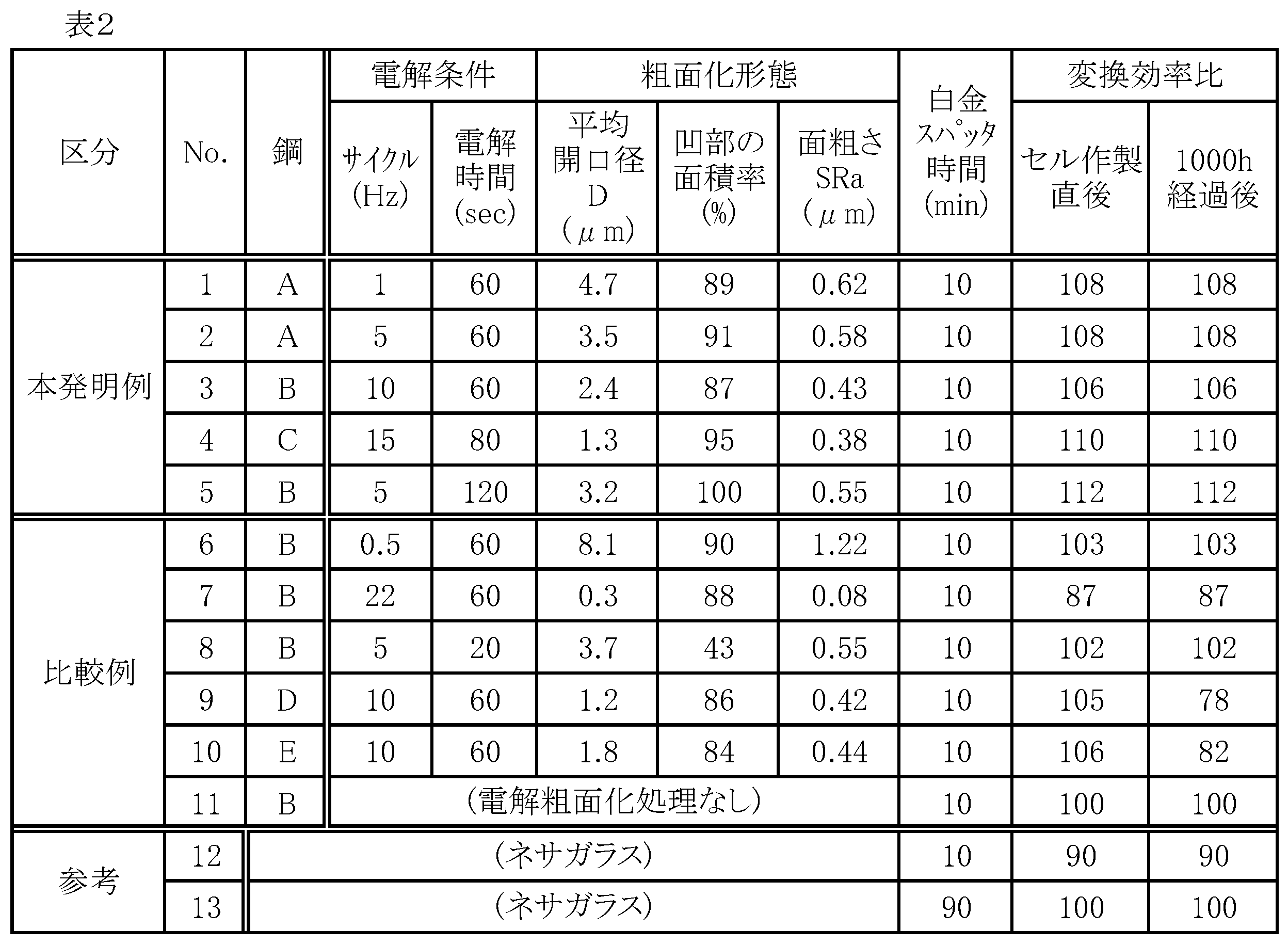
表2からわかるように、本発明例のものはいずれも白金スパッタ時間が10minと短いにもかかわらず、変換効率比は100を超えており、90minスパッタのネサガラスを対極に使用した場合よりも高い値を示し、経時劣化も認められない。10minスパッタのネサガラスでは変換効率比が90と低いことから、本発明のステンレス鋼板からなる電極材料を用いることによって白金の使用量の低減が可能となる。また、比較例No.11の電解なしの場合よりも変換効率が高いのは表面形状による拡散反射効果のためであると考えられる。
一方、比較例No.6は孔食状凹部の平均開口径Dが大きいため変換効率の向上効果が小さかった。No.7は平均開口径Dが小さすぎたことおよび面粗さSRaが小さすぎたことにより電解なし(No.11)よりも変換効率が低かった。No.8は孔食状凹部の面積率が低すぎたことにより変換効率の向上効果が小さかった。No.9およびNo.10はステンレス鋼のMo含有量あるいはさらにCr含有量が低いことにより、電解液に対する耐食性が劣っており、1000h後の変換効率は著しく低下している。これは白金コーティング膜内のピンホールを介して電解液中へFeやCrなどの鋼中成分が溶出したことが原因と推察される。白金コーティングの膜厚を十分に増大させることによりこの問題を解消することが可能である。
図6に示すタイプの電池セルを以下のようにして構成し、変換効率を調べた。
光電極の基板として、実施例1で対極に使用したものと同じ粗面化ステンレス鋼の板材および粗面化処理していないステンレス鋼の板材(いずれも白金の触媒層を形成していないもの)を用意した。対極の材料として、白金を1minスパッタコーティングしたITO膜付きPENフィルムを用意した。実施例1と同様の手順で小型の電池セルを作製し、変換効率を測定した。ただし、前記[1]の工程ではITO膜付きPENフィルムの代わりに上記ステンレス鋼基板を用い、光電極を作製した。光照射は対極側より行った。
光電極の基板として、実施例1で対極に使用したものと同じ粗面化ステンレス鋼の板材および粗面化処理していないステンレス鋼の板材(いずれも白金の触媒層を形成していないもの)を用意した。対極の材料として、白金を1minスパッタコーティングしたITO膜付きPENフィルムを用意した。実施例1と同様の手順で小型の電池セルを作製し、変換効率を測定した。ただし、前記[1]の工程ではITO膜付きPENフィルムの代わりに上記ステンレス鋼基板を用い、光電極を作製した。光照射は対極側より行った。
結果を表3に示す。ここで変換効率比とは、参考欄に記載した光電極にITO膜付きPENフィルムを使用したときの変換効率を100とした場合の比の値と定義する。
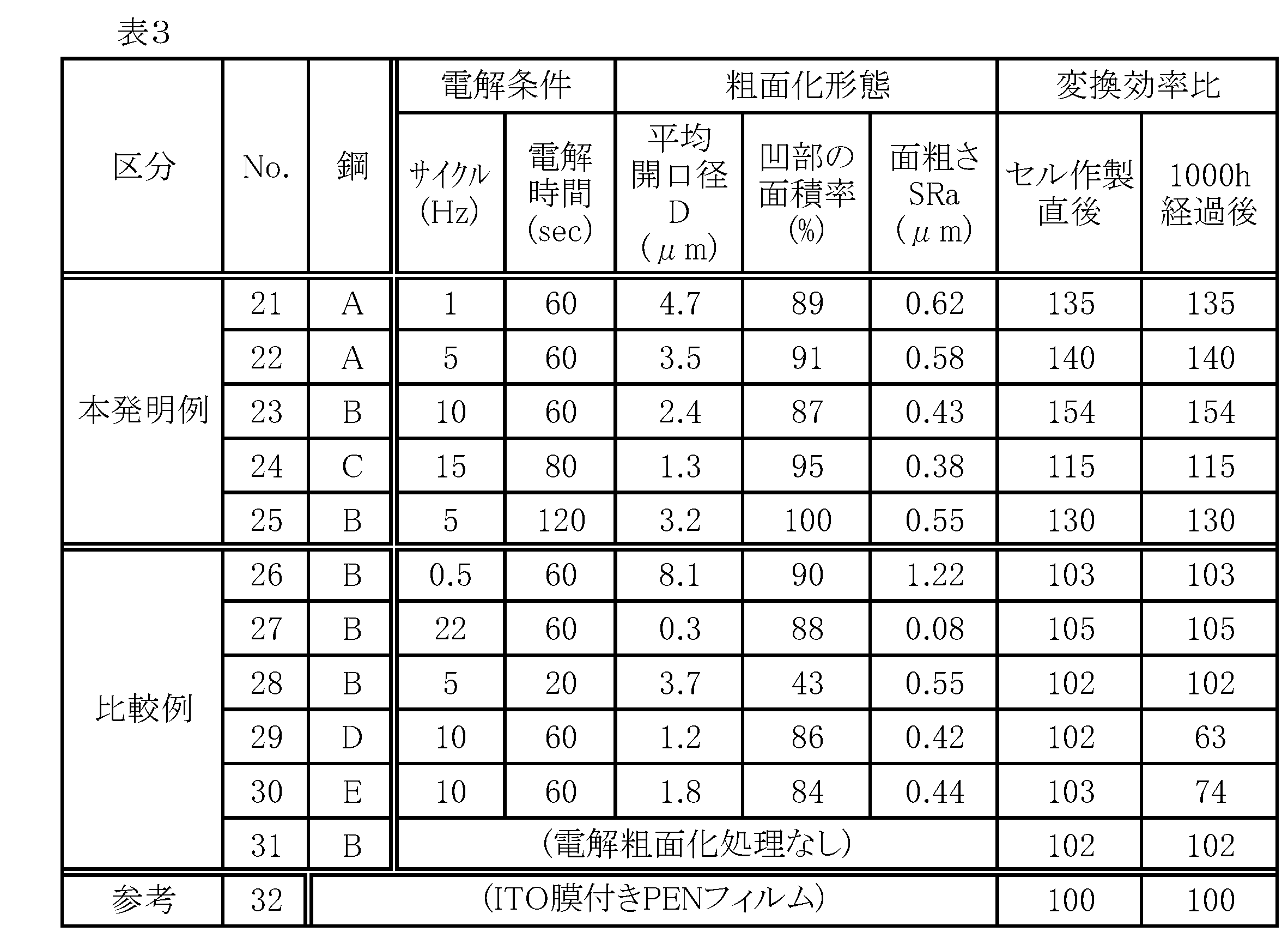
表3からわかるように、本発明例のものはいずれも変換効率比は100を超えており、ITO膜付きPENフィルムを光電極に使用した場合よりも高い値を示し、経時劣化も認められない。No.29およびNo.30はステンレス鋼のMo含有量あるいはさらにCr含有量が低いことにより、電解液に対する耐食性が劣っており、実施例1と同様に1000h後の変換効率は著しく低下している。本発明例のステンレス鋼を使用した場合(No.21~25)は比較例(No.26~31)のステンレス鋼板を使用した場合に比べて変換効率の向上効果が高い。これは、実施例1と同様に表面形状による拡散反射効果のためであると考えられる。
1 太陽電池
2 透明基板
3 光電極
4 基板
5 対極
6 光電変換層
7 TiO2粒子
8 Ru色素
9 電解質溶液
10 触媒層
11 負荷
20 入射光
21 ステンレス鋼板
30 本発明の電極材料からなる対極
40 本発明の電極材料からなる光電極
2 透明基板
3 光電極
4 基板
5 対極
6 光電変換層
7 TiO2粒子
8 Ru色素
9 電解質溶液
10 触媒層
11 負荷
20 入射光
21 ステンレス鋼板
30 本発明の電極材料からなる対極
40 本発明の電極材料からなる光電極
Claims (9)
- Crを17~32質量%、Moを0.8~3質量%の範囲で含有し、表面に面積率50%以上の割合で平均開口径D:0.5~5μmの孔食状凹部を有するステンレス鋼板からなる色素増感型太陽電池の電極材料。
- 前記ステンレス鋼板はJIS G4305に規定されるフェライト系鋼種において、Crを17~32質量%、Moを0.8~3質量%の範囲で含有するものである請求項1に記載の色素増感型太陽電池の電極材料。
- 質量%で、C:0.15%以下、Si:1.2%以下、Mn:1.2%以下、Cr:17~32%、Mo:0.8~3%、N:0.025%以下、残部実質的にFeの組成を有し、フェライト相組織を呈し、表面に面積率50%以上の割合で平均開口径D:0.5~5μmの孔食状凹部を有するステンレス鋼板からなる色素増感型太陽電池の電極材料。
- 前記ステンレス鋼板は、さらに質量%で、Al:5%以下、Ti:1%以下、Nb:1%以下、Cu:3%以下、Ni:5%以下の1種以上を含有するものである請求項3に記載の色素増感型太陽電池の電極材料。
- 前記ステンレス鋼板の孔食状凹部を有する表面は、面粗さSRaが0.1~1.5μmである請求項1~4のいずれかに記載の色素増感型太陽電池の電極材料。
- 質量%で、C:0.15%以下、Si:1.2%以下、Mn:1.2%以下、Cr:17~32%、Mo:0.8~3%、N:0.025%以下、残部実質的にFeの組成を有し、フェライト相組織を呈するステンレス鋼板に対して、Fe3+濃度1~50g/Lの塩化第二鉄水溶液中で、アノード電解時の電流密度を1.0~10.0kA/m2、カソード電解時の電流密度を0.1~3.0kA/m2とした1~20Hzの交番電解を施すことにより、当該鋼板表面に面積率50%以上の割合で平均開口径D:0.5~5μmの孔食状凹部を形成する色素増感型太陽電池の電極材料の製造方法。
- 前記ステンレス鋼板として、さらに質量%で、Al:5%以下、Ti:1%以下、Nb:1%以下、Cu:3%以下、Ni:5%以下の1種以上を含有するものを用いる請求項6に記載の色素増感型太陽電池の電極材料の製造方法。
- 請求項1~5のいずれかに記載の電極材料を基材として、その孔食状凹部を有するステンレス鋼板表面に触媒層または光電変換層を形成した色素増感型太陽電池の電極。
- 触媒層は白金めっきを施すことによって形成されたものである請求項8に記載の色素増感型太陽電池の電極。
Priority Applications (2)
| Application Number | Priority Date | Filing Date | Title |
|---|---|---|---|
| PCT/JP2009/062597 WO2011004494A1 (ja) | 2009-07-10 | 2009-07-10 | 色素増感型太陽電池の電極材料およびその製造方法並びに電極 |
| JP2011521758A JP5430658B2 (ja) | 2009-07-10 | 2009-07-10 | 色素増感型太陽電池の電極 |
Applications Claiming Priority (1)
| Application Number | Priority Date | Filing Date | Title |
|---|---|---|---|
| PCT/JP2009/062597 WO2011004494A1 (ja) | 2009-07-10 | 2009-07-10 | 色素増感型太陽電池の電極材料およびその製造方法並びに電極 |
Publications (1)
| Publication Number | Publication Date |
|---|---|
| WO2011004494A1 true WO2011004494A1 (ja) | 2011-01-13 |
Family
ID=43428932
Family Applications (1)
| Application Number | Title | Priority Date | Filing Date |
|---|---|---|---|
| PCT/JP2009/062597 Ceased WO2011004494A1 (ja) | 2009-07-10 | 2009-07-10 | 色素増感型太陽電池の電極材料およびその製造方法並びに電極 |
Country Status (2)
| Country | Link |
|---|---|
| JP (1) | JP5430658B2 (ja) |
| WO (1) | WO2011004494A1 (ja) |
Cited By (1)
| Publication number | Priority date | Publication date | Assignee | Title |
|---|---|---|---|---|
| JP2015082549A (ja) * | 2013-10-22 | 2015-04-27 | 国立大学法人東京海洋大学 | 光電極及びその製造方法、並びに該光電極を備えた海洋微生物燃料電池 |
Citations (4)
| Publication number | Priority date | Publication date | Assignee | Title |
|---|---|---|---|---|
| JPH11273753A (ja) * | 1998-03-25 | 1999-10-08 | Sekisui Chem Co Ltd | 色素増感型光電池 |
| JP2004356229A (ja) * | 2003-05-27 | 2004-12-16 | Matsushita Electric Works Ltd | 有機光電変換素子 |
| JP2005222941A (ja) * | 2004-02-03 | 2005-08-18 | Samsung Sdi Co Ltd | 染料感応太陽電池及びその製造方法 |
| JP2009026532A (ja) * | 2007-07-18 | 2009-02-05 | Nisshin Steel Co Ltd | 色素増感型太陽電池の電極材料 |
Family Cites Families (1)
| Publication number | Priority date | Publication date | Assignee | Title |
|---|---|---|---|---|
| JP2009200008A (ja) * | 2008-02-25 | 2009-09-03 | Nisshin Steel Co Ltd | 色素増感型太陽電池の電極材料およびその製造方法並びに電極 |
-
2009
- 2009-07-10 JP JP2011521758A patent/JP5430658B2/ja not_active Expired - Fee Related
- 2009-07-10 WO PCT/JP2009/062597 patent/WO2011004494A1/ja not_active Ceased
Patent Citations (4)
| Publication number | Priority date | Publication date | Assignee | Title |
|---|---|---|---|---|
| JPH11273753A (ja) * | 1998-03-25 | 1999-10-08 | Sekisui Chem Co Ltd | 色素増感型光電池 |
| JP2004356229A (ja) * | 2003-05-27 | 2004-12-16 | Matsushita Electric Works Ltd | 有機光電変換素子 |
| JP2005222941A (ja) * | 2004-02-03 | 2005-08-18 | Samsung Sdi Co Ltd | 染料感応太陽電池及びその製造方法 |
| JP2009026532A (ja) * | 2007-07-18 | 2009-02-05 | Nisshin Steel Co Ltd | 色素増感型太陽電池の電極材料 |
Cited By (1)
| Publication number | Priority date | Publication date | Assignee | Title |
|---|---|---|---|---|
| JP2015082549A (ja) * | 2013-10-22 | 2015-04-27 | 国立大学法人東京海洋大学 | 光電極及びその製造方法、並びに該光電極を備えた海洋微生物燃料電池 |
Also Published As
| Publication number | Publication date |
|---|---|
| JP5430658B2 (ja) | 2014-03-05 |
| JPWO2011004494A1 (ja) | 2012-12-13 |
Similar Documents
| Publication | Publication Date | Title |
|---|---|---|
| EP2337144B1 (en) | Dye-sensitized solar cells | |
| JP2009200008A (ja) | 色素増感型太陽電池の電極材料およびその製造方法並びに電極 | |
| Yang et al. | Ternary platinum alloy counter electrodes for high-efficiency dye-sensitized solar cells | |
| Kadakia et al. | Novel F-doped IrO2 oxygen evolution electrocatalyst for PEM based water electrolysis | |
| KR101502807B1 (ko) | 색소 증감형 태양 전지 및 그 제조 방법 | |
| JP4620794B1 (ja) | 色素増感型太陽電池 | |
| JP5171139B2 (ja) | 色素増感型太陽電池の電極材料 | |
| JP5227194B2 (ja) | 積層電極 | |
| JP5430658B2 (ja) | 色素増感型太陽電池の電極 | |
| JP2008034110A (ja) | 色素増感型太陽電池の電極材 | |
| JP5566082B2 (ja) | 色素増感型太陽電池の対向電極およびその製造方法並びに電池 | |
| JP4788838B2 (ja) | 色素増感型太陽電池 | |
| JP2014220201A (ja) | 色素増感型太陽電池用基板およびその製造方法 | |
| JP2012113839A (ja) | 色素増感型太陽電池用金属薄膜、及び色素増感型太陽電池素子 | |
| JP5593881B2 (ja) | 色素増感型太陽電池 | |
| HK1160988B (en) | Dye-sensitized solar cells | |
| JP2011108463A (ja) | 色素増感型太陽電池の光電極およびその製造方法並びに電池 | |
| JP2011249148A (ja) | 燃料電池用セパレータ材料、それを用いた燃料電池用セパレータ及び燃料電池スタック、並びに燃料電池用セパレータ材料の製造方法 | |
| JP2011044318A (ja) | 色素増感型太陽電池およびその製造方法 | |
| JP2013149424A (ja) | 色素増感太陽電池用電極材、色素増感太陽電池 | |
| HK1169518A (en) | Dye-sensitized solar cell and method for manufacturing the same | |
| JP2011108465A (ja) | 可視光透過性を有する色素増感型太陽電池およびその製造方法 | |
| JP2006164593A (ja) | 色素増感型太陽電池用金属電極 | |
| Wang | Tianlong Zheng, Juan Wang, Qunhui | |
| WO2014208610A1 (ja) | 導電部材 |
Legal Events
| Date | Code | Title | Description |
|---|---|---|---|
| 121 | Ep: the epo has been informed by wipo that ep was designated in this application |
Ref document number: 09847096 Country of ref document: EP Kind code of ref document: A1 |
|
| WWE | Wipo information: entry into national phase |
Ref document number: 2011521758 Country of ref document: JP |
|
| NENP | Non-entry into the national phase |
Ref country code: DE |
|
| 122 | Ep: pct application non-entry in european phase |
Ref document number: 09847096 Country of ref document: EP Kind code of ref document: A1 |