WO2011002054A1 - Heating cooking appliance - Google Patents
Heating cooking appliance Download PDFInfo
- Publication number
- WO2011002054A1 WO2011002054A1 PCT/JP2010/061243 JP2010061243W WO2011002054A1 WO 2011002054 A1 WO2011002054 A1 WO 2011002054A1 JP 2010061243 W JP2010061243 W JP 2010061243W WO 2011002054 A1 WO2011002054 A1 WO 2011002054A1
- Authority
- WO
- WIPO (PCT)
- Prior art keywords
- heater
- passage
- circulation duct
- heating chamber
- gas
- Prior art date
Links
Images


Classifications
-
- F—MECHANICAL ENGINEERING; LIGHTING; HEATING; WEAPONS; BLASTING
- F24—HEATING; RANGES; VENTILATING
- F24C—DOMESTIC STOVES OR RANGES ; DETAILS OF DOMESTIC STOVES OR RANGES, OF GENERAL APPLICATION
- F24C15/00—Details
- F24C15/32—Arrangements of ducts for hot gases, e.g. in or around baking ovens
- F24C15/322—Arrangements of ducts for hot gases, e.g. in or around baking ovens with forced circulation
- F24C15/325—Arrangements of ducts for hot gases, e.g. in or around baking ovens with forced circulation electrically-heated
Definitions
- the present invention relates to a cooking device that performs cooking by circulating gas in a heating chamber.
- FIG. 7 is a side sectional view showing a conventional cooking device.
- the heating cooker 1 is provided with a heating chamber 2 that opens and closes a front surface by a door 3 and stores a cooked product.
- a suction port 2a is opened on the back surface of the heating chamber 2, and an air outlet 2b is opened on the ceiling surface.
- the inlet 2a and the outlet 2b are connected by a circulation duct 20 disposed around the heating chamber 2.
- a blower 31 facing the suction port 2 a is provided in the back surface portion 21 of the circulation duct 20, and a heater 32 is disposed on the ceiling portion 22 of the circulation duct 20.
- the air in the heating chamber 2 flows into the circulation duct 20 from the suction port 2a as indicated by an arrow A1.
- the air flowing into the circulation duct 20 is led from the back side to the ceiling portion 22 as shown by the arrow A2, and is heated by the heater 32.
- the air heated by the heater 32 is blown into the heating chamber 2 from the blower outlet 2b as indicated by an arrow A3.
- the air in the heating chamber 2 circulates through the circulation duct 20, and the cooked food is cooked by the air blown into the heating chamber 2 from the outlet 2 b and the radiant heat of the heater 32.
- An object of the present invention is to provide a cooking device capable of extending the life of the heater and shortening the cooking time.
- the present invention provides a heating chamber for storing a cooked product, a circulation duct for connecting a suction port and an outlet opening in a wall surface of the heating chamber, and a blower disposed in the circulation duct. And a heater arranged in the circulation duct above the heating chamber, and the gas in the heating chamber is taken into the circulation duct from the suction port by driving the blower, and the temperature is raised by the heater.
- the circulation duct has first and second passages that branch upstream from the heater, and the first passage is gas in the upstream portion of the heater. And the second passage guides the gas to the downstream portion of the heater and joins the gas flowing through the first passage.
- a gas composed of air or steam in the heating chamber flows into the circulation duct via the suction port.
- the gas flowing into the circulation duct branches into the first and second passages, and is led to a heater arranged above the heating chamber.
- the second passage guides the gas to the downstream portion of the heater
- the first passage guides the gas to the upstream portion of the heater
- the gas flowing through the first and second passages is heated by the heater, and blown out from the outlet into the heating chamber.
- the gas in the heating chamber circulates through the circulation duct, and the cooked food is cooked by the gas heated by the heater and the radiant heat of the heater.
- the present invention is characterized in that, in the cooking device having the above-described configuration, the second passage is arranged above the first passage through the partition plate.
- circulates a circulation duct branches up and down with a partition plate, and merges in the downstream part of a heater.
- the partition plate has a small hole facing a predetermined position upstream of the first passage. According to this configuration, a part of the gas flowing through the second passage flows into the first passage through the small hole.
- the present invention is characterized in that the small hole is provided immediately above the heater in the cooking device having the above-described configuration.
- the present invention is characterized in that, in the heating cooker having the above-described configuration, a guide plate for guiding the gas to the small hole by blocking the gas flow path flowing through the second passage is provided.
- the present invention provides a heating chamber for storing a cooked product, a circulation duct connecting a suction port and an outlet opening in a wall surface of the heating chamber, a blower disposed in the circulation duct, and the heating chamber.
- a heating heater disposed in the upper circulation duct, the gas in the heating chamber is taken into the circulation duct from the suction port by driving the blower, and the temperature is raised by the heating heater from the outlet.
- the circulation duct has first and second passages that are branched upstream of the heater and separated by a partition plate, and the heater is disposed in the first passage.
- the partition plate has a small hole facing a predetermined position of the first passage.
- a gas composed of air or steam in the heating chamber flows into the circulation duct via the suction port.
- the gas flowing into the circulation duct is branched into the first and second passages by the partition plate, and the temperature of the gas flowing through the first passage is raised by the heater disposed in the first passage.
- the gas flowing through the second passage is supplied to a predetermined position of the first passage through a small hole, and is heated by a heater.
- the gas heated by the heater is blown out from the outlet into the heating chamber.
- the gas in the heating chamber circulates through the circulation duct, and the cooked food is cooked by the gas heated by the heater and the radiant heat of the heater.
- the present invention is characterized in that the small hole is provided immediately above the heater in the cooking device having the above-described configuration.
- the present invention is characterized in that, in the heating cooker having the above-described configuration, a guide plate for guiding the gas to the small hole by blocking the gas flow path flowing through the second passage is provided.
- the circulation duct branches into the first passage for guiding the gas to the upstream portion of the heater and the second passage for introducing the gas to the downstream portion of the heater and merges with the first passage. Cooling can be performed uniformly from the upstream portion to the downstream portion. Accordingly, since the surface temperature of the heater can be kept low, the life of the heater can be extended. Moreover, the electric power supplied to a heater can be enlarged and cooking time can be shortened.
- the circulation duct branches into the first passage in which the heater is arranged and the second passage having a small hole facing the first passage. Therefore, the heater is locally heated in the first passage. Gas can be supplied from the second passage through the small hole to the part. Thereby, it can cool uniformly from the upstream part of a heater to a downstream part. Accordingly, since the surface temperature of the heater can be kept low, the life of the heater can be extended. Moreover, the electric power supplied to a heater can be enlarged and cooking time can be shortened.
- FIG. 1 is a side sectional view showing a heating cooker according to the first embodiment.
- the heating cooker 1 is provided with a heating chamber 2 that opens and closes a front surface by a door 3 and stores a cooked product.
- a suction port 2a is opened at the back of the heating chamber 2, and a blowout port 2b is opened at the ceiling.
- the inlet 2a and the outlet 2b are connected by a circulation duct 20 disposed around the heating chamber 2.
- a blower 31 facing the suction port 2 a is provided in the back surface portion 21 of the circulation duct 20.
- the ceiling portion 22 of the circulation duct 20 is divided by the partition plate 25 into a lower first passage 23 and an upper second passage 24.
- a heater 32 is disposed in the first passage 23.
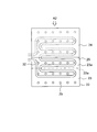
- FIG. 2 shows a plan view of the ceiling portion 22 of the circulation duct 20.
- the upper side is the back side of the heating cooker 1.
- the heater 32 is a meandering tubular sheathed heater that is supplied with power from one side.
- the partition plate 25 is made of stainless steel or the like and covers the upstream portion of the heater 32 to isolate the first and second passages 23 and 24.
- the downstream portion of the heater 32 is covered with the upper surface plate 22 a of the ceiling portion 22, and an opening 23 a is formed in the horizontal direction between the upper surface plate 22 a and the partition plate 25.
- the first passage 23 and the second passage 24 are joined by the opening 23a.
- the air in the heating chamber 2 flows into the circulation duct 20 from the suction port 2a as indicated by an arrow A1.
- the air flowing into the circulation duct 20 is guided from the back side to the ceiling portion 22 as indicated by an arrow A2, and is branched into the first and second passages 23 and 24 by the partition plate 25.
- the air passing through the first passage 23 advances from the upstream portion to the downstream portion of the heater 32.
- the air passing through the second passage 24 joins the first passage 23 through the opening 23a as indicated by an arrow A22 and is guided to the downstream portion of the heater 32.
- the air heated by the contact with the heater 32 is blown into the heating chamber 2 from the outlet 2b as indicated by an arrow A3.
- the air in the heating chamber 2 circulates through the circulation duct 20, and the cooked food is cooked by the air blown into the heating chamber 2 from the outlet 2 b and the radiant heat of the heater 32.
- the ceiling portion 22 of the circulation duct 20 guides air to the upstream portion of the heater 32, and the second passage joins the first passage 23 by introducing gas to the downstream portion of the heater 32. Since it branches into the passage 24, it is possible to cool uniformly from the upstream portion to the downstream portion of the heater 32. Therefore, since the surface temperature of the heater 32 can be kept low, the life of the heater 32 can be extended. Moreover, the electric power supplied to the heater 32 can be increased, and the cooking time can be shortened.
- the circulation duct 20 can be easily branched. Moreover, since the flow path area of the 2nd channel
- the partition plate 25 may be provided with a small hole 25 a that has a smaller opening area than the opening 23 a and faces a predetermined position in the upstream portion of the first passage 23.
- the small holes 25a are provided at both end portions on the inflow side of the second passage 24, for example. Part of the air flowing through the second passage 24 flows into the first passage 23 through the small hole 25a. Thereby, air can be supplied from the second passage 24 through the small holes 25 to the portion where the air in the first passage 23 is difficult to reach, and the upstream portion of the heater 32 can be cooled more uniformly.
- the partition plate 25 with a guide plate 25b that guides air to the small hole 25a because air can be reliably supplied to the first passage 23 from the small hole 25a.
- the small hole 25a may be provided immediately above the meandering tubular heater 32. Thereby, the air supplied from the small hole 25a can be in direct contact with the heater 32 whose surface temperature rises, and the heater 32 can be cooled.
- FIG. 4 shows a side sectional view of the cooking device of the second embodiment.
- the same reference numerals are given to the same parts as those in the first embodiment shown in FIGS.
- This embodiment is different from the first embodiment in the configuration of the partition plate 25 of the ceiling portion 22 of the circulation duct 20. Other parts are the same as those in the first embodiment.
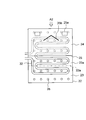
- FIG. 5 shows a plan view of the ceiling 22 of the circulation duct 20.
- the partition plate 25 covers the entire surface of the first passage 23 and is provided with a plurality of small holes 25 a facing the first passage 23.
- the small hole 25 a is provided immediately above the tubular heater 32.
- the air flowing into the circulation duct 20 from the heating chamber 2 through the suction port 2a as shown by the arrow A1 is guided to the ceiling portion 22 from the back side as shown by the arrow A2.
- the air passing through the first passage 23 proceeds from the upstream portion to the downstream portion of the heater 32.
- the air passing through the second passage 24 flows into the first passage 23 through the small hole 25a. At this time, the air supplied from the small holes 25a can be in direct contact with the heater 32 whose surface temperature rises to cool the heater 32.
- the air heated by the contact with the heater 32 is blown into the heating chamber 2 from the outlet 2b as indicated by an arrow A3.
- the air in the heating chamber 2 circulates through the circulation duct 20, and the cooked food is cooked by the air blown into the heating chamber 2 from the outlet 2 b and the radiant heat of the heater 32.
- the ceiling portion 22 of the circulation duct 20 branches into a first passage having the heater 32 and a second passage 24 having a small hole 25a facing the first passage 23.
- gas can be supplied from the second passage 24 through the small hole 25a to the portion of the first passage 23 where the temperature is locally high.
- it can cool uniformly from the upstream part of the heater 32 to a downstream part. Therefore, since the surface temperature of the heater 32 can be kept low, the life of the heater 32 can be extended.
- the electric power supplied to the heater 32 can be increased, and the cooking time can be shortened.
- the small holes 25a may be provided at other positions in the first passage 23 where the temperature is high. At this time, a guide plate 25b for guiding air to the small hole 25a may be provided as shown in FIG.
- FIG. 6 shows a front sectional view of the heating cooker of the third embodiment.
- the same reference numerals are given to the same parts as those in the first embodiment shown in FIGS.
- steam is supplied to the heating chamber 2 for cooking, and the arrangement of the circulation duct 20 is different from that in the first embodiment.
- Other parts are the same as those in the first embodiment.
- a plurality of installation sections 6 are provided on both sides of the heating chamber 2 in the vertical direction, and a mounting tray 7 on which the food is placed is installed on the installation section 6. Thereby, the mounting tray 7 can be cooked in a plurality of stages. Note that an opening (not shown) through which an airflow can pass is provided in a handle portion around the mounting tray 7.
- the suction port 2a is opened at the upper part of the right side surface of the heating chamber 2, and the outlets 2b and 2c are opened at the ceiling surface and the left side surface, respectively.
- the suction port 2a is arranged above the upper installation portion 6.
- the blower outlet 2b is formed by many small holes.
- the side outlet 2c is widely open from the upper part of the upper installation part 6 to the lower part of the lower installation part 6.
- the air outlet 2c may be divided into upper and lower parts.
- the inlet 2a and the outlet 2c are connected by a circulation duct 20.
- a blower 31 facing the suction port 2 a is provided in the right side surface portion 26 of the circulation duct 20.
- the ceiling portion 22 of the circulation duct 20 is configured in the same manner as in the first embodiment, and is divided into a lower first passage 23 and an upper second passage 24 by a partition plate 25.
- a heater 32 is disposed in the first passage 23.
- An outlet 2c is opened in the left side surface portion 27 of the circulation duct 20.
- a steam supply unit 10 is attached to the lower part of the right side surface of the heating chamber 2.
- the steam supply unit 10 embeds a steam generating heater 13 composed of a sheathed heater in a metal container having a water supply port 11 and a discharge port 12.
- the water supply port 11 is supplied with water for generating steam from a detachable water supply tank (not shown).
- the steam generating heater 13 evaporates the water supplied from the water supply port 11 to generate steam.
- the discharge port 12 opens to the right side surface portion 26 of the circulation duct 20 and discharges the steam generated in the steam supply unit 10 into the circulation duct 20.
- the heater 32 is configured in the same manner as in the first embodiment, and heats the steam flowing through the ceiling portion 22 of the circulation duct 20. Thereby, steam can be maintained at a predetermined temperature and cooking with saturated steam or superheated steam can be performed.
- the cooking device 1 configured as described above, when cooking is placed on the placing tray 7 and cooking is started, water is supplied from the water supply tank (not shown) to the steam supply unit 10 through the water supply port 11.
- the water supplied to the steam supply unit 10 is evaporated by the steam generating heater 13 to generate steam.
- Steam flowing into the circulation duct 20 from the discharge port 10 is supplied to the heating chamber 2 from the blower outlet 2b by driving the blower 31.
- the steam in the heating chamber 2 flows into the circulation duct 20 from the suction port 2a as shown by the arrow A1 by driving the blower 31.
- the steam that has flowed into the circulation duct 20 is guided from the side to the ceiling portion 22 as indicated by an arrow A 2, and is branched into first and second passages 23 and 24 by a partition plate 25.
- the steam passing through the first passage 23 advances from the upstream portion to the downstream portion of the heater 32.
- the steam passing through the second passage 24 joins the first passage 23 through the opening 23a (see FIG. 2) as indicated by an arrow A22 and is guided to the downstream portion of the heater 32.
- the steam heated by the contact with the heater 32 is blown into the heating chamber 2 from the outlet 2b as indicated by an arrow A3. Further, a part of the steam heated by the heater 32 flows from the ceiling portion 22 into the left side surface portion 27 as indicated by an arrow A4. The steam flowing into the left side surface portion 27 is blown out into the heating chamber 2 from the blowout port 2c as shown by arrows A5, A7, A8. The steam blown out from the outlet 2c flows in the horizontal direction in the heating chamber 2 as shown by an arrow A9, and flows into the circulation duct 20 through the inlet 2a as shown by an arrow A10.
- the steam in the heating chamber 2 circulates through the circulation duct 20, and the cooked food is cooked by the steam heated by the heater 32 and the radiant heat of the heater 32.
- cooking with saturated steam may be performed while maintaining the steam at a temperature in the vicinity of 100 ° C., or cooking with superheated steam may be performed while maintaining the steam at 100 ° C. or higher (for example, 300 ° C.).
- the ceiling portion 22 of the circulation duct 20 guides gas to the upstream portion of the heater 32 and the downstream portion of the heater 32 to introduce the gas. Since the first passage 23 and the second passage 24 that merges branch off, the heater 32 can be cooled uniformly from the upstream portion to the downstream portion. Therefore, since the surface temperature of the heater 32 can be kept low, the life of the heater 32 can be extended. Moreover, the electric power supplied to the heater 32 can be increased, and the cooking time can be shortened.
- air may be heated by the heater 32 and cooking with hot air may be performed, or the suction port 2 a may be provided on the back surface of the heating chamber 2.
- you may comprise the partition plate 25 similarly to above-mentioned FIG. 3, FIG.
- the present invention can be used in a cooking device that performs cooking by circulating gas in a heating chamber.
Landscapes
- Engineering & Computer Science (AREA)
- Chemical & Material Sciences (AREA)
- Combustion & Propulsion (AREA)
- Mechanical Engineering (AREA)
- General Engineering & Computer Science (AREA)
- Electric Stoves And Ranges (AREA)
- Baking, Grill, Roasting (AREA)
- Commercial Cooking Devices (AREA)
Abstract
Description
2 加熱室
2a 吸込口
2b、2c 吹出口
3 扉
6 設置部
7 載置トレイ
10 蒸気供給部
11 給水口
12 吐出口
13 蒸気発生ヒータ
20 循環ダクト
21 背面部
22 天井部
23 第1通路
24 第2通路
25 仕切板
25a 小孔
25b 案内部
26 右側面部
27 左側面部
31 送風機
32 加熱ヒータ DESCRIPTION OF
Claims (8)
- 調理物を収納する加熱室と、前記加熱室の壁面に開口する吸込口と吹出口とを連結する循環ダクトと、前記循環ダクト内に配される送風機と、前記加熱室の上方の前記循環ダクト内に配される加熱ヒータとを備え、前記送風機の駆動によって前記加熱室内の気体を前記吸込口から前記循環ダクトに取り入れ、前記加熱ヒータにより昇温して前記吹出口から前記加熱室に吹き出す加熱調理器において、前記循環ダクトは前記加熱ヒータよりも上流で分岐する第1、第2通路を有し、第1通路が前記加熱ヒータの上流部に気体を導くとともに、第2通路が前記加熱ヒータの下流部に気体を導いて第1通路を流通する気体と合流することを特徴とする加熱調理器。 A heating chamber for storing the cooked food, a circulation duct for connecting a suction port and an outlet opening in the wall surface of the heating chamber, a blower disposed in the circulation duct, and the circulation duct above the heating chamber A heating heater disposed in the interior, and by heating the blower, the gas in the heating chamber is taken into the circulation duct from the suction port, heated by the heater, and blown out from the outlet to the heating chamber In the cooker, the circulation duct has first and second passages branched upstream of the heater, the first passage guides gas to the upstream portion of the heater, and the second passage is the heater. A heating cooker characterized in that the gas is led to the downstream part of the gas and joined with the gas flowing through the first passage.
- 第2通路が仕切板を介して第1通路の上方に配されることを特徴とする請求項1に記載の加熱調理器。 The heating cooker according to claim 1, wherein the second passage is arranged above the first passage through a partition plate.
- 前記仕切板は第1通路の上流部の所定位置に臨む小孔を有することを特徴とする請求項2に記載の加熱調理器。 The cooking plate according to claim 2, wherein the partition plate has a small hole facing a predetermined position in the upstream portion of the first passage.
- 前記小孔が前記加熱ヒータの直上に設けられることを特徴とする請求項3に記載の加熱調理器。 The heating cooker according to claim 3, wherein the small hole is provided immediately above the heater.
- 第2通路を流通する気体の流路を遮って前記小孔に気体を案内する案内板を設けたことを特徴とする請求項4に記載の加熱調理器。 The cooking device according to claim 4, wherein a guide plate for guiding the gas to the small hole is provided by blocking a flow path of the gas flowing through the second passage.
- 調理物を収納する加熱室と、前記加熱室の壁面に開口する吸込口と吹出口とを連結する循環ダクトと、前記循環ダクト内に配される送風機と、前記加熱室の上方の前記循環ダクト内に配される加熱ヒータとを備え、前記送風機の駆動によって前記加熱室内の気体を前記吸込口から前記循環ダクトに取り入れ、前記加熱ヒータにより昇温して前記吹出口から前記加熱室に吹き出す加熱調理器において、前記循環ダクトは前記加熱ヒータよりも上流で分岐して仕切板で隔離される第1、第2通路を有し、前記加熱ヒータを第1通路に配するとともに、前記仕切板が第1通路の所定位置に臨む小孔を有することを特徴とする加熱調理器。 A heating chamber for storing the cooked food, a circulation duct for connecting a suction port and an outlet opening in the wall surface of the heating chamber, a blower disposed in the circulation duct, and the circulation duct above the heating chamber A heating heater disposed in the interior, and by heating the blower, the gas in the heating chamber is taken into the circulation duct from the suction port, heated by the heater, and blown out from the outlet to the heating chamber In the cooker, the circulation duct has first and second passages branched upstream from the heater and separated by a partition plate, the heater is arranged in the first passage, and the partition plate is A heating cooker having a small hole facing a predetermined position of the first passage.
- 前記小孔が前記加熱ヒータの直上に設けられることを特徴とする請求項6に記載の加熱調理器。 The heating cooker according to claim 6, wherein the small hole is provided immediately above the heater.
- 第2通路を流通する気体の流路を遮って前記小孔に気体を案内する案内板を設けたことを特徴とする請求項7に記載の加熱調理器。 The cooking device according to claim 7, wherein a guide plate for guiding the gas to the small hole is provided by blocking a flow path of the gas flowing through the second passage.
Priority Applications (4)
| Application Number | Priority Date | Filing Date | Title |
|---|---|---|---|
| JP2011520976A JP5307893B2 (en) | 2009-07-03 | 2010-07-01 | Cooker |
| CN201080028255.9A CN102472497B (en) | 2009-07-03 | 2010-07-01 | Heating cooking appliance |
| US13/375,133 US8614408B2 (en) | 2009-07-03 | 2010-07-01 | Heating cooking appliance |
| EP10794222.9A EP2450631A4 (en) | 2009-07-03 | 2010-07-01 | Heating cooking appliance |
Applications Claiming Priority (2)
| Application Number | Priority Date | Filing Date | Title |
|---|---|---|---|
| JP2009-158533 | 2009-07-03 | ||
| JP2009158533 | 2009-07-03 |
Publications (1)
| Publication Number | Publication Date |
|---|---|
| WO2011002054A1 true WO2011002054A1 (en) | 2011-01-06 |
Family
ID=43411122
Family Applications (1)
| Application Number | Title | Priority Date | Filing Date |
|---|---|---|---|
| PCT/JP2010/061243 WO2011002054A1 (en) | 2009-07-03 | 2010-07-01 | Heating cooking appliance |
Country Status (5)
| Country | Link |
|---|---|
| US (1) | US8614408B2 (en) |
| EP (1) | EP2450631A4 (en) |
| JP (1) | JP5307893B2 (en) |
| CN (1) | CN102472497B (en) |
| WO (1) | WO2011002054A1 (en) |
Cited By (3)
| Publication number | Priority date | Publication date | Assignee | Title |
|---|---|---|---|---|
| JP2013053768A (en) * | 2011-09-01 | 2013-03-21 | Sharp Corp | Heating cooker |
| US20140054245A1 (en) * | 2012-08-27 | 2014-02-27 | Jeffrey A. Loesche | Downspout filter device |
| JP2016114287A (en) * | 2014-12-15 | 2016-06-23 | シャープ株式会社 | Heating cooker |
Families Citing this family (10)
| Publication number | Priority date | Publication date | Assignee | Title |
|---|---|---|---|---|
| WO2014056327A1 (en) * | 2012-10-11 | 2014-04-17 | Yu Shigao | Fryer using air circulation to fry food more quickly |
| KR101586532B1 (en) * | 2013-04-30 | 2016-01-18 | 동부대우전자 주식회사 | Cooking apparatus |
| KR101577497B1 (en) * | 2013-04-30 | 2015-12-14 | 동부대우전자 주식회사 | Cooking apparatus |
| JP2015162207A (en) * | 2014-02-28 | 2015-09-07 | 株式会社リコー | Destination management system, communication system, program, and destination management method |
| JP5896579B1 (en) * | 2015-03-11 | 2016-03-30 | シャープ株式会社 | Cooker |
| AU2016325845A1 (en) * | 2015-09-24 | 2018-04-26 | Yukio Hirose | Cooker |
| KR102018469B1 (en) * | 2015-11-02 | 2019-09-04 | 미쓰비시덴키 가부시키가이샤 | Heating cooker |
| WO2022052316A1 (en) * | 2020-09-10 | 2022-03-17 | 广东美的白色家电技术创新中心有限公司 | Steam apparatus |
| DE102020212058A1 (en) | 2020-09-24 | 2022-03-24 | BSH Hausgeräte GmbH | Household steamer with superheater |
| DE102020216520A1 (en) | 2020-12-22 | 2022-06-23 | BSH Hausgeräte GmbH | Household steamer with superheater module |
Citations (3)
| Publication number | Priority date | Publication date | Assignee | Title |
|---|---|---|---|---|
| JP2002162039A (en) * | 2000-11-10 | 2002-06-07 | Lg Electronics Inc | Heating system of microwave-oven heater |
| JP2004361069A (en) * | 2003-05-15 | 2004-12-24 | Sharp Corp | Heating cooking device |
| JP2009002627A (en) | 2007-06-25 | 2009-01-08 | Toshiba Corp | Cooker |
Family Cites Families (8)
| Publication number | Priority date | Publication date | Assignee | Title |
|---|---|---|---|---|
| JPH0552352A (en) * | 1991-08-23 | 1993-03-02 | Sanyo Electric Co Ltd | Microwave oven |
| KR100301904B1 (en) * | 1997-11-15 | 2001-11-22 | 구자홍 | Apparatus for cooling microwave oven with halogen lamp |
| ATE384415T1 (en) * | 2000-11-30 | 2008-02-15 | Lg Electronics Inc | HEATING DEVICE FOR A MICROWAVE OVEN |
| DE202004015290U1 (en) * | 2004-10-01 | 2006-02-09 | Klouda, Jaroslav | Apparatus for equalizing energy input into foodstuffs fermenting on baking trays, having inlet and/or outlet sections of air circulating blower divided into at least two heatable guide channels |
| CN100487318C (en) * | 2004-10-27 | 2009-05-13 | 乐金电子(天津)电器有限公司 | Household electronic cooking stove |
| JP2007064530A (en) * | 2005-08-30 | 2007-03-15 | Toshiba Corp | Heating cooker |
| JP2007198654A (en) * | 2006-01-25 | 2007-08-09 | Toshiba Corp | Heating cooker |
| JP4791983B2 (en) * | 2007-02-20 | 2011-10-12 | 株式会社東芝 | Cooker |
-
2010
- 2010-07-01 US US13/375,133 patent/US8614408B2/en not_active Expired - Fee Related
- 2010-07-01 JP JP2011520976A patent/JP5307893B2/en not_active Expired - Fee Related
- 2010-07-01 CN CN201080028255.9A patent/CN102472497B/en not_active Expired - Fee Related
- 2010-07-01 WO PCT/JP2010/061243 patent/WO2011002054A1/en active Application Filing
- 2010-07-01 EP EP10794222.9A patent/EP2450631A4/en not_active Withdrawn
Patent Citations (3)
| Publication number | Priority date | Publication date | Assignee | Title |
|---|---|---|---|---|
| JP2002162039A (en) * | 2000-11-10 | 2002-06-07 | Lg Electronics Inc | Heating system of microwave-oven heater |
| JP2004361069A (en) * | 2003-05-15 | 2004-12-24 | Sharp Corp | Heating cooking device |
| JP2009002627A (en) | 2007-06-25 | 2009-01-08 | Toshiba Corp | Cooker |
Non-Patent Citations (1)
| Title |
|---|
| See also references of EP2450631A4 |
Cited By (3)
| Publication number | Priority date | Publication date | Assignee | Title |
|---|---|---|---|---|
| JP2013053768A (en) * | 2011-09-01 | 2013-03-21 | Sharp Corp | Heating cooker |
| US20140054245A1 (en) * | 2012-08-27 | 2014-02-27 | Jeffrey A. Loesche | Downspout filter device |
| JP2016114287A (en) * | 2014-12-15 | 2016-06-23 | シャープ株式会社 | Heating cooker |
Also Published As
| Publication number | Publication date |
|---|---|
| CN102472497B (en) | 2015-06-24 |
| EP2450631A1 (en) | 2012-05-09 |
| US8614408B2 (en) | 2013-12-24 |
| JP5307893B2 (en) | 2013-10-02 |
| JPWO2011002054A1 (en) | 2012-12-13 |
| CN102472497A (en) | 2012-05-23 |
| US20120074124A1 (en) | 2012-03-29 |
| EP2450631A4 (en) | 2017-12-13 |
Similar Documents
| Publication | Publication Date | Title |
|---|---|---|
| JP5307893B2 (en) | Cooker | |
| JP4106382B2 (en) | Cooker | |
| JP4457166B2 (en) | Cooker | |
| JP6128341B2 (en) | Cooker | |
| US9388992B2 (en) | Gas oven range | |
| KR101307659B1 (en) | Water drainage system and steam cooker comprising the same | |
| JP5453010B2 (en) | Cooker | |
| KR20080024029A (en) | Cooking apparatus | |
| JP2010007984A (en) | Heating cooker | |
| KR101580683B1 (en) | Component room air flow system for steam oven | |
| JP2010266106A (en) | Cooker | |
| JP4957201B2 (en) | Cooker | |
| JP5732231B2 (en) | Cooker | |
| KR101014436B1 (en) | Steam generator and steam oven comprising the same | |
| KR20060125295A (en) | Oven | |
| JP6209733B2 (en) | Cooker | |
| JP4689535B2 (en) | Cooker | |
| KR100780335B1 (en) | Heating cooker | |
| JP6156725B2 (en) | Cooker | |
| JP5452692B2 (en) | IH cooking heater | |
| JP4287796B2 (en) | Steam cooker | |
| JP2013165820A (en) | Rack for cooking and cooker | |
| JP2011043260A (en) | Heating cooker | |
| JP2007017076A (en) | Heating cooker |
Legal Events
| Date | Code | Title | Description |
|---|---|---|---|
| WWE | Wipo information: entry into national phase |
Ref document number: 201080028255.9 Country of ref document: CN |
|
| 121 | Ep: the epo has been informed by wipo that ep was designated in this application |
Ref document number: 10794222 Country of ref document: EP Kind code of ref document: A1 |
|
| WWE | Wipo information: entry into national phase |
Ref document number: 2011520976 Country of ref document: JP |
|
| WWE | Wipo information: entry into national phase |
Ref document number: 13375133 Country of ref document: US |
|
| WWE | Wipo information: entry into national phase |
Ref document number: 2010794222 Country of ref document: EP |
|
| NENP | Non-entry into the national phase |
Ref country code: DE |