WO2011001654A1 - 導光シートとそれを用いた可動接点体、スイッチ - Google Patents
導光シートとそれを用いた可動接点体、スイッチ Download PDFInfo
- Publication number
- WO2011001654A1 WO2011001654A1 PCT/JP2010/004260 JP2010004260W WO2011001654A1 WO 2011001654 A1 WO2011001654 A1 WO 2011001654A1 JP 2010004260 W JP2010004260 W JP 2010004260W WO 2011001654 A1 WO2011001654 A1 WO 2011001654A1
- Authority
- WO
- WIPO (PCT)
- Prior art keywords
- light
- base material
- light emitting
- guide sheet
- movable contact
- Prior art date
- Legal status (The legal status is an assumption and is not a legal conclusion. Google has not performed a legal analysis and makes no representation as to the accuracy of the status listed.)
- Ceased
Links
Images


Classifications
-
- H—ELECTRICITY
- H01—ELECTRIC ELEMENTS
- H01H—ELECTRIC SWITCHES; RELAYS; SELECTORS; EMERGENCY PROTECTIVE DEVICES
- H01H13/00—Switches having rectilinearly-movable operating part or parts adapted for pushing or pulling in one direction only, e.g. push-button switch
- H01H13/02—Details
-
- H—ELECTRICITY
- H01—ELECTRIC ELEMENTS
- H01H—ELECTRIC SWITCHES; RELAYS; SELECTORS; EMERGENCY PROTECTIVE DEVICES
- H01H13/00—Switches having rectilinearly-movable operating part or parts adapted for pushing or pulling in one direction only, e.g. push-button switch
- H01H13/70—Switches having rectilinearly-movable operating part or parts adapted for pushing or pulling in one direction only, e.g. push-button switch having a plurality of operating members associated with different sets of contacts, e.g. keyboard
- H01H13/83—Switches having rectilinearly-movable operating part or parts adapted for pushing or pulling in one direction only, e.g. push-button switch having a plurality of operating members associated with different sets of contacts, e.g. keyboard characterised by legends, e.g. Braille, liquid crystal displays, light emitting or optical elements
-
- H—ELECTRICITY
- H01—ELECTRIC ELEMENTS
- H01H—ELECTRIC SWITCHES; RELAYS; SELECTORS; EMERGENCY PROTECTIVE DEVICES
- H01H13/00—Switches having rectilinearly-movable operating part or parts adapted for pushing or pulling in one direction only, e.g. push-button switch
- H01H13/70—Switches having rectilinearly-movable operating part or parts adapted for pushing or pulling in one direction only, e.g. push-button switch having a plurality of operating members associated with different sets of contacts, e.g. keyboard
- H01H13/702—Switches having rectilinearly-movable operating part or parts adapted for pushing or pulling in one direction only, e.g. push-button switch having a plurality of operating members associated with different sets of contacts, e.g. keyboard with contacts carried by or formed from layers in a multilayer structure, e.g. membrane switches
-
- H—ELECTRICITY
- H01—ELECTRIC ELEMENTS
- H01H—ELECTRIC SWITCHES; RELAYS; SELECTORS; EMERGENCY PROTECTIVE DEVICES
- H01H9/00—Details of switching devices, not covered by groups H01H1/00 - H01H7/00
- H01H9/18—Distinguishing marks on switches, e.g. for indicating switch location in the dark; Adaptation of switches to receive distinguishing marks
-
- H—ELECTRICITY
- H01—ELECTRIC ELEMENTS
- H01H—ELECTRIC SWITCHES; RELAYS; SELECTORS; EMERGENCY PROTECTIVE DEVICES
- H01H2219/00—Legends
- H01H2219/054—Optical elements
- H01H2219/056—Diffuser; Uneven surface
-
- H—ELECTRICITY
- H01—ELECTRIC ELEMENTS
- H01H—ELECTRIC SWITCHES; RELAYS; SELECTORS; EMERGENCY PROTECTIVE DEVICES
- H01H2219/00—Legends
- H01H2219/054—Optical elements
- H01H2219/062—Light conductor
-
- H—ELECTRICITY
- H01—ELECTRIC ELEMENTS
- H01H—ELECTRIC SWITCHES; RELAYS; SELECTORS; EMERGENCY PROTECTIVE DEVICES
- H01H2219/00—Legends
- H01H2219/054—Optical elements
- H01H2219/064—Optical isolation of switch sites
Definitions
- the present invention relates to a light guide sheet mainly used for operation of various electronic devices, a movable contact body using the same, and a switch.
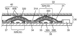
- This switch includes a movable contact body 36, a wiring board 37, and a fixed contact 38.
- the movable contact body 36 includes a light guide sheet 33, a light-transmitting film-like base sheet 34, and a dome-shaped movable contact 35 made of a conductive metal thin plate.
- the light guide sheet 33 has a light-transmissive and film-like base material 31 and a light emitting part 32 composed of a plurality of convex portions 320 provided at predetermined positions on the lower surface of the base material 31.
- a notch is provided between the light emitting units 32.
- a plurality of cutout portions 31A are provided in a C shape around the light emitting portion 32A, and a T-shaped cutout portion 31B is provided between the light emitting portion 32B and the light emitting portion 32C. ing.
- the base sheet 34 is affixed to the lower surface of the light guide sheet 33 at a predetermined position on the outer periphery of the upper surface by an adhesive (not shown).
- a plurality of movable contacts 35 are attached to the lower surface of the base sheet 34 below each light emitting portion 32.
- a plurality of wiring patterns (not shown) are formed on the upper and lower surfaces of the wiring board 37.
- a plurality of fixed contacts 38 are provided on the upper surface of the wiring board 37.
- the fixed contact 38 includes a substantially circular center fixed contact 38A and a substantially horseshoe-shaped or substantially ring-shaped outer fixed contact 38B surrounding the fixed contact 38A.
- each movable contact 35 is placed on the outer fixed contact 38B, and the movable contact 35 is placed on the upper surface of the wiring board 37 so that the center of the lower surface of the movable contact 35 faces the central fixed contact 38A with a predetermined gap.
- a body 36 is affixed.
- the light emitting element 39 such as a light emitting diode is mounted on the upper surface of the wiring substrate 37 on the side of the light guide sheet 33 so as to project light to the end of the light guide sheet 33.
- the light emitting element 39A is disposed on the right side of the light emitting section 32A
- the light emitting element 39B is disposed on the lower side of the light emitting section 32B with the light emitting surface facing the end surface of the base 31.
- the switch configured in this way is mounted on the operation surface of an electronic device such as a mobile phone.
- a light-transmissive and film-like display sheet 40 is disposed below the operation surface.
- On the lower surface of the display sheet 40 a plurality of display portions 40 ⁇ / b> B are formed by cutting out predetermined portions of the coating portion 40 ⁇ / b> A formed by printing or the like into shapes such as characters and symbols.
- the display unit 40 ⁇ / b> B is disposed above the light emitting unit 32 of the light guide sheet 33.
- the plurality of fixed contacts 38 and the plurality of light emitting elements 39 are connected to an electronic circuit (not shown) of the device via a wiring pattern or the like.
- the movable contact 35 is elastically reversed upward by the elastic restoring force, and the center of the lower surface of the movable contact 35 is separated from the central fixed contact 38A. Thereby, the central fixed contact 38A and the outer fixed contact 38B are electrically disconnected.
- the various functions of the device are switched according to the electrical contact / separation of the fixed contact 38.
- the light emitting element 39A and the light emitting element 39B emit light.
- the orange light enters the light guide sheet 33 from the right end surface and the green light from the lower end surface, and the base material 31 Go inward while reflecting inside.
- this light is diffused and reflected by the convex portions 320 such as the light emitting portion 32A and the light emitting portion 32B on the lower surface of the base material 31, and illuminates the display portion 40B of the upper display sheet 40 from below. Therefore, for example, the display unit 40B above the light emitting unit 32A is illuminated in orange, and the display unit 40B above the light emitting unit 32B is illuminated in green. Therefore, even when the surrounding is dark, the user can identify the display of characters and symbols on the display unit 40B and can easily operate the device.
- the display sheet 40 when the user presses the display sheet 40, the upper surface of the light guide sheet 33 is pressed, whereby the movable contact 35 is elastically reversed and the fixed contact 38 is electrically connected. Moreover, the light of the light emitting element 39 is introduced into the light guide sheet 33 from the end face, and the plurality of light emitting units 32 emit light, whereby the plurality of display units 40B of the display sheet 40 are illuminated.
- the light emission colors of the light emitting element 39A and the light emitting element 39B are different.
- a notch 31A and a notch 31B are formed between the plurality of light emitting portions 32.
- the cutout portions 31A and 31B are formed at predetermined positions in order to prevent light of different colors emitted from the light emitting elements 39A and 39B from being mixed in the light guide sheet 33 and illuminating the light emitting portion 32 with mixed light emission colors. The light is blocked.
- the light emitting unit 32A may be turned off and the light emitting unit 32B may be turned on. Also in this case, the notches 31A and 31B prevent the portion that should have been extinguished from being lightly illuminated by the light illuminating other portions.
- a switch is disclosed in Patent Document 1, for example.
- the crosspieces 31 ⁇ / b> C and 31 ⁇ / b> D to which the base material 31 is connected are not formed around the light emitting part 32 ⁇ / b> A and the light emitting part 32 ⁇ / b> B. Therefore, it is difficult to completely shield light between the light emitting units 32. Therefore, as the number of light emitting elements 39 is increased and the brightness is increased, light mixing and leakage are more likely to occur.
- the present invention is a light guide sheet capable of preventing various mixing and leakage of light emitted from a plurality of light emitting elements and capable of various illuminations, and a movable contact body and a switch using the light guide sheet.
- the light guide sheet of the present invention guides light emitted from the light projecting unit.
- This light guide sheet has a film-like base material, a light emitting portion formed on the base material, and a strip-shaped light shielding portion.
- the light emitting part reflects or scatters light transmitted through the substrate.
- the light shielding portion is formed in the base material by coloring the base material in a color that can absorb the light emitted from the light projecting portion at a place other than the light emitting portion.
- the light emitting part of another light guide sheet of the present invention is composed of at least one of a plurality of convex parts and a plurality of concave parts.
- the light-shielding part is formed in the base material at a place other than at least one of the plurality of convex parts and the plurality of concave parts.
- the light shielding part in the base material, when a plurality of light emitting parts are provided, mixing and leakage of light between them can be prevented. Alternatively, leakage of light to the outside can be prevented. Alternatively, light can be emitted in different colors in two regions of one light emitting unit. In this way, it is possible to produce a light guide sheet that is easy to see and capable of various illuminations.
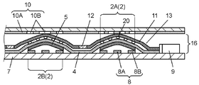
- FIG. 1 is a cross-sectional view of a movable contact body according to Embodiment 1 of the present invention.
- FIG. 2 is a plan view of the movable contact body shown in FIG.
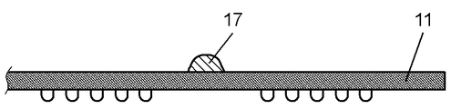
- FIG. 3 is a sectional view of a switch using the movable contact body shown in FIG. 4A is a partial cross-sectional view showing a process of forming a light shielding portion on a base material in the movable contact body shown in FIG.
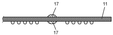
- FIG. 4B is a partial cross-sectional view showing another process of forming the light shielding portion on the base material in the movable contact body shown in FIG. 1.
- FIG. 1 is a cross-sectional view of a movable contact body according to Embodiment 1 of the present invention.
- FIG. 2 is a plan view of the movable contact body shown in FIG.
- FIG. 3 is a sectional view of a switch using the movable contact body shown in FIG. 4A is a partial cross-sectional view showing a
- FIG. 4C is a partial cross-sectional view showing still another process of forming the light shielding portion on the base material in the movable contact body shown in FIG.
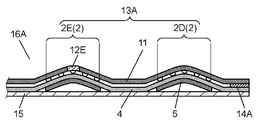
- FIG. 5 is a sectional view of a movable contact body according to Embodiment 2 of the present invention.
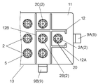
- FIG. 6 is a plan view of the movable contact body shown in FIG.
- FIG. 7A is a plan view of another movable contact body according to Embodiment 2 of the present invention.
- FIG. 7B is an enlarged view of a display unit provided on the movable contact body shown in FIG. 7A.
- FIG. 8 is a cross-sectional view showing another configuration of the movable contact body shown in FIG. 7A.
- FIG. 9 is a sectional view showing another configuration of the movable contact body shown in FIG.
- FIG. 10 is a cross-sectional view of a conventional switch.
- FIG. 11 is a plan view of the movable contact body shown in FIG.
- the movable contact body 16 includes a light guide sheet 13, a film-like base sheet 4, and a movable contact 5.
- the light guide sheet 13 includes a film-like base material 11, a plurality of convex portions 20, and includes a light emitting part 2 formed on the base material 11 and a strip-shaped light shielding part 12.
- the light-transmitting substrate 11 is made of a flexible sheet such as polyurethane, silicone, styrene, or polycarbonate.
- the convex portion 20 is formed in a dot shape by printing or the like at a predetermined position on the lower surface of the base material 11 using polyester, epoxy, or the like such as white or milky white.
- the light emitting unit 2 formed on the base material 11 reflects or scatters light transmitted through the base material 11 to the outside.
- the light shielding portion 12 is formed in the base material 11 between the plurality of light emitting portions 2.
- the light shielding part 12 is formed around the light emitting part 2A or between the light emitting part 2B and the light emitting part 2C. That is, the light-shielding part 12 of the connected strip shape and dark colors, such as black and dark blue, is provided so that the light emission parts 2A, 2B, 2C, etc. may be enclosed.
- the light-shielding part 12 compares the ink prepared by dissolving a dark dye in a solvent in which the base material 11 can swell, sprayed onto the surface of the base material 11 with an ink jet or the like, and heated at a predetermined temperature for a predetermined time. Can be formed easily.
- an ink is prepared by dissolving an azo dye in a solvent such as acetone or cyclohexanone.
- silicone is used for the substrate 11
- an ink is prepared by dissolving an oil-soluble metal-containing dye in gasoline or benzene.
- polycarbonate is used for the substrate 11, an ink is prepared by dispersing an azo dye in toluene, xylene or the like.
- an ink obtained by adding a resin such as acrylic or phenoxy to these solvents may be printed on the surface of the base material 11 by screen printing or the like, and heated to infiltrate the dark dye into the base material 11.
- the light shielding portion 12 colored in a dark color such as black or dark blue can be formed. That is, the light shielding part 12 is formed in the base material 11 by coloring the base material 11 at a place other than the light emitting part 2.
- the base sheet 4 is made of a flexible film such as polyethylene terephthalate or polycarbonate. A predetermined portion on the outer periphery of the base sheet 4 is attached to the lower surface of the light guide sheet 13 with an adhesive 14 such as acrylic or silicone.
- the dome-shaped movable contact 5 is formed of a thin metal plate such as a copper alloy or steel. The movable contact 5 is attached to the lower surface of the base sheet 4 at a position below the light emitting unit 2. In this way, the movable contact body 16 is configured.
- a film-like separator 15 such as polyethylene terephthalate is attached to the base sheet 4 so as to cover the entire lower surface of the base sheet 4.
- the separator 15 prevents dust and the like from adhering to the lower surface of the movable contact 5 during storage and transport.
- FIG. 3 is a sectional view of a switch using the movable contact body 16.
- This switch includes a movable contact body 16, a wiring board 7, and a plurality of light emitting elements 9 that are light projecting portions.
- the plate-like wiring substrate 7 is made of a film such as polyethylene terephthalate or polycarbonate, or a plate such as paper phenol or glass-filled epoxy.
- a plurality of wiring patterns (not shown) are formed on the upper and lower surfaces of the wiring substrate 7 using copper or the like.
- a plurality of fixed contacts 8 are provided on the upper surface of the wiring board 7 using copper, carbon, or the like.
- Each of the fixed contacts 8 includes a circular central fixed contact 8A and a horseshoe-shaped or ring-shaped outer fixed contact 8B surrounding the fixed fixed contact 8A.
- the movable contact body 16 from which the separator 15 has been peeled off is attached to the upper surface of the wiring board 7.
- the movable contact body 16 is attached so that the outer periphery of each movable contact 5 is placed on the outer fixed contact 8B, and the center of the lower surface of the movable contact 5 is opposed to the central fixed contact 8A with a predetermined gap. Is done.
- the light emitting element 9 such as a light emitting diode is mounted on the upper surface of the wiring substrate 7 on the side of the light guide sheet 13, and is provided at a position where light can be projected on the end portion of the base material 11 of the light guide sheet 13.
- the light emitting element 9A is arranged on the right side of the light emitting unit 2A
- the light emitting element 9B is arranged on the lower side of the light emitting unit 2B, with the light emitting surface facing the end surface of the base material 11. In this way, the switch is configured.
- a light-transmissive and film-like display sheet 10 is disposed above the light guide sheet 13.
- a painted portion 10A is formed on the lower surface of the display sheet 10 by printing or the like, and a plurality of display portions 10B are formed by cutting out predetermined portions of the painted portion 10A into shapes such as letters and symbols.
- the display unit 10 ⁇ / b> B is disposed above the light emitting unit 2 of the light guide sheet 13.
- the switch configured in this way is mounted on the operation surface of an electronic device such as a mobile phone.
- a plurality of central fixed contacts 8A, outer fixed contacts 8B, and a plurality of light emitting elements 9 are connected to an electronic circuit (not shown) of the device via a wiring pattern or the like.
- the movable contact 5 When the user releases the pressing force on the display sheet 10, the movable contact 5 is elastically reversed upward by the elastic restoring force, and the center of the lower surface of the movable contact 5 is separated from the central fixed contact 8A. Thereby, the center fixed contact 8A and the outer fixed contact 8B are electrically disconnected.
- the various functions of the device can be switched according to the electrical contact / separation of the fixed contact 8.
- the light emitting element 9A and the light emitting element 9B emit light.
- the emission color of the light emitting element 9A is orange and the light emitting element 9B is green
- orange light enters the light guide sheet 13 from the right end surface and green light from the lower end surface, and the inside of the base material 11 Go inward while reflecting.
- this light is diffused or reflected by the convex portions 20 such as the light emitting portion 2A and the light emitting portion 2B, and illuminates the display portion 10B of the upper display sheet 10 from below.
- the display unit 10B located above the light emitting unit 2A is illuminated in orange, and the display unit 10B is illuminated in green above the light emitting unit 2B. Therefore, even when the surroundings are dark, the user can identify the display of characters and symbols on the display unit 10B, and can easily operate the device.
- a light-shielding part 12 which is a belt and colored in a dark color such as black or dark blue is formed so as to surround them.
- the light shielding part 12 is formed in the base material 11 by coloring the base material 11 in a color that can absorb the light emitted from the light emitting element 9 at a place other than the light emitting part 2.
- the plurality of convex portions 20 form a plurality of light emitting portions 2, and the light shielding portion 12 is formed between the plurality of light emitting portions 2.
- the light emitting unit 2A emits orange light and the light emitting unit 2B emits green light, and the upper display unit 10B is illuminated with different colors, the orange light and the green light are in the light guide sheet 13. Will not be mixed in.
- the light emitting unit 2A is completely surrounded by a C-shaped light shielding unit 12A, and the light emitting unit 2B is completely surrounded by a light shielding unit 12B in a C shape. Yes. Therefore, the orange light of the light emitting unit 2A and the green light of the light emitting unit 2B are shielded by the light shielding units 12A and 12B. As a result, the light from the light emitting element 9A does not leak to the light emitting part 2B, and the light from the light emitting element 9B does not leak to the light emitting part 2A. Therefore, the display unit 10B is not illuminated with an emission color in which orange or green light is mixed.
- the light emitting unit 2A emits light by the light emitting element 9A. Since this light is almost completely blocked by the light shielding part 12A, the light emitting part 2B and the light emitting part 2C are prevented from emitting light lightly by the light from the light emitting element 9A.
- the light-shielding portion 12 colored in a dark color is formed in the base 11 between the light emitting portions 2A and 2B so as to surround the light emitting portion 2A and the light emitting portion 2B, respectively. Then, light is shielded between the light emitting units 2A, 2B, 2C and the like. Therefore, mixing and leakage of light to other light emitting portions can be prevented, and various illuminations can be easily made.
- the light-shielding portion 12 is formed relatively easily by applying an ink obtained by dissolving a dark dye that can penetrate the base material 11 to the surface of the base material 11 by ink jet or screen printing. can do.
- coating an ink to the surface of the base material 11 heating is normally performed at predetermined temperature, and a dye osmose
- a preferred method for forming the light shielding portion 12 when the substrate 11 is thick will be described with reference to FIGS. 4A to 4C.
- 4A to 4C are partial cross-sectional views showing a process of forming the light shielding portion 12 on the base material 11.
- the base material 11 is as thick as about 0.2 mm, for example, as shown in FIG. 4A, when the ink 17 is applied only on one side, the speed at which the dye penetrates the base material 11 and is colored darkly is shallow on the top surface. It becomes slower as it goes deeper below the part. Therefore, it takes about 10 to 40 minutes at a temperature of about 100 to 160 ° C. to form the light shielding portion 12.
- the ink 17 it is preferable to apply the ink 17 to both surfaces of the substrate 11.
- the light-shielding part 12 can be formed by heating in a short time.
- the width of the light shielding portion 12 is 0.5 mm or more.
- the width of the light shielding portion 12 can be formed to a narrow width of about 0.3 mm. Therefore, the light shielding part 12 can be formed even in a position where the space between the light emitting parts 2 is narrow.
- the groove 11A may be formed on one or both sides of the base material 11 by laser processing or the like, and the thickness of the base material 11 into which the ink 17 penetrates may be reduced. Even in this case, the narrow light-shielding portion 12 can be formed in a short time.
- (Embodiment 2) 5 and 6 are a sectional view and a plan view of the movable contact body according to the second embodiment of the present invention.
- the same reference numerals are given to the same components as those in the first embodiment, and detailed description may be omitted.
- the light emitting part 2 composed of a plurality of convex parts 20 such as white or milky white is formed on the lower surface of the base material 11.
- a belt-like dark shade portion 12 ⁇ / b> C is provided on the outer periphery of the base material 11 so as to surround the plurality of light emitting portions 2.
- the hole part 11B is formed in the base material 11, and the light-shielding part 12D is provided also in the outer periphery of the hole part 11B so that the hole part 11B may be enclosed.
- a strip-shaped light shielding portion 12E is formed in the intermediate portion of the base material 11 so as to pass through the center of the light emitting portion 2E.
- the plurality of convex portions 20 form the light emitting portion 2E, and the light shielding portion 12E is formed so as to pass through the light emitting portion 2E.
- the light guide sheet 13A is configured.
- the light shielding portions 12C, 12D, and 12E are formed in the same manner as the light shielding portion 12 of the first embodiment. That is, the light shielding parts 12C and 12D are also colored with a color that can absorb light emitted from the light emitting element 9 that is a light projecting part at a place other than the light emitting part 2 provided. Is formed inside.
- the light-shielding part 12E is colored in a color that can absorb light emitted from the light-emitting element 9 that is a light projecting part at a place other than the plurality of convex parts 20 provided. Is formed.
- a plurality of movable contacts 5 are affixed to the lower surface of the base sheet 4 below the light emitting section 2 and a predetermined portion on the outer periphery of the base sheet 4 is adhered to the light guide sheet by the adhesive 14A. It is affixed to the lower surface of 13A.
- the adhesive 14A is formed in a dark color such as black or dark blue that absorbs light from the light emitting elements 9A and 9B.
- the movable contact body 16A formed in this way is attached to the upper surface of the wiring board 7 on which a plurality of fixed contacts 8 are formed as described in the first embodiment with reference to FIG. Is done.
- the display unit 10B of the display sheet 10 is disposed above the light emitting unit 2 of the light guide sheet 13A.
- the light emitting element 9A is on the upper side of the light emitting unit 2D, and the light emitting element 9B is It arrange
- a light shielding part 12 ⁇ / b> E is formed in the intermediate part of the base material 11. Therefore, the orange light that the light emitting element 9A casts into the light guide sheet 13A from the upper end surface and the green light that the light emitting element 9B casts into the light guide sheet 13A from the lower end surface are shielded by the light shielding unit 12E. Mixing of light is prevented.
- the light shielding part 12E is formed through the center of the light emitting part 2E. Therefore, unlike the light emitting unit 2D and the light emitting unit 2F, the light emitting unit 2E emits light in different colors in the upper half and the lower half.
- the entire light emitting portion 2D and the like above the substrate 11 emits light in orange
- the lower light emitting portion 2F and the like emit green light respectively.
- the upper half of the light emitting unit 2E having the light shielding unit 12E formed at the center emits light in a different color in orange and the lower half in green.
- a light shielding part 12C surrounding the plurality of light emitting parts 2 is provided on the outer periphery of the base material 11, and a light shielding part 12D surrounding the hole part 11B is provided on the outer periphery of the hole part 11B. Therefore, the light incident on the base material 11 is prevented from leaking out of the base material 11 and into the hole 11B. That is, the light shielding part 12C and the light shielding part 12D shield the light incident on the base material 11, and this light does not leak outside and illuminate unnecessary portions in the device.
- the light shielding portions 12C and 12D are formed in a bluish black to absorb the yellowness of the base material 11. Thereby, it is possible to prevent the light emitting unit 2 arranged particularly away from the light emitting element 9 from emitting yellowish light, and it is also possible to cause the plurality of light emitting units 2 to emit light with uniform brightness without variation. It becomes possible.
- the light of the light emitting element 9 is prevented from leaking out from the position of the adhesive 14A by forming the adhesive 14A for attaching a predetermined position on the outer periphery of the base sheet 4 to the lower surface of the light guide sheet 13A in a dark color. You can also.
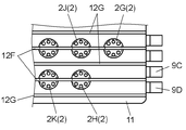
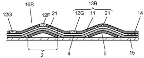
- a strip-shaped dark light-shielding part 12 ⁇ / b> F that passes through the center of each light-emitting part 2, and a plurality of light-shielding parts 12 ⁇ / b> G are provided between the outer periphery of the substrate 11 and the light-emitting part 2. Also good. With such a configuration, the display unit 10B of the display sheet 10 can be illuminated more variously.
- a light shielding part 12F is formed at the center of the light emitting part 2H and the light emitting part 2K.
- the light emitting elements 9C and 9D arranged on the right side of the substrate 11 are caused to emit light.
- the emission color of the light emitting element 9C is orange and the light emitting element 9D is green
- the upper half of the light emitting part 2H and the light emitting part 2K emits light in orange and the lower half emits light in different colors.
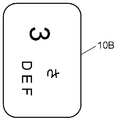
- the display unit 10B above the light emitting unit 2H displays numbers in the upper half and characters in the lower half as shown in FIG. 7B, the upper half numbers are orange and the lower half characters. Is illuminated in green.
- the light emitting element 9C and the light emitting element 9D have the same color, for example, white, and only the light emitting element 9C emits light, only the upper half of the light emitting unit 2H emits light. In this case, only the upper half of the display unit 10B is illuminated.
- the light emitting element 9D is caused to emit light, only the lower half of the light emitting portion 2H emits light and only the lower half characters of the display portion 10B are illuminated.
- the light shielding part 12F is provided so as to pass through the center of the light emitting part 2H, etc., and the upper half and the lower half of the light emitting part 2H emit light in different colors, or only one of the upper half and the lower half emits light. can do. In this way, more diverse illumination of the display unit 10B is possible.
- the elastic reversal of the movable contact 5 may be impaired because many portions are fixed with an adhesive as described above. is there.
- the light shielding portion 12F that passes through the center of each light emitting portion 2 is formed by infiltrating the dye into the base material 11, so that the light shielding portion 12 is integral with the base material 11. For this reason, the elastic reversal of the movable contact 5 is not impaired, and the user can obtain a good operation feeling.
- the light shielding portions 12F and 12G or the light shielding portions 12C, 12D, and 12E as described above can be simultaneously formed by ink jetting, screen printing, or the like when the light guide sheet is manufactured. Therefore, even if the number of light-shielding portions increases, it takes less time to manufacture, and a movable contact body and a switch can be manufactured at a low cost.
- the emission color of the light emitting element 9 is blue light having a wavelength of about 420 to 480 nm, yellow light having a wavelength of about 520 to 600 nm, red light having a wavelength of about 650 to 800 nm, or white light in which blue light and yellow light are mixed. Etc. Regardless of which light the light emitting element 9 emits, the light shielding portion 12 and the like are formed in a dark color, and a material that absorbs the light is selected as a dye to prevent light leakage and mixing more reliably. it can.
- a dye according to the light emission color of the light emitting element 9 by selecting a dye according to the light emission color of the light emitting element 9 and infiltrating it into the base material 11 to form a dark color light shielding portion, it is possible to more reliably shield each light emission color.
- a carotenoid or azo dye that absorbs blue light is used.
- a phthalocyanine dye that absorbs yellow light is used.
- an anthraquinone dye that absorbs red light is used.
- a mixture of these dyes can be used for a plurality of light emitting elements 9 having different colors.
- the dye used for forming the light shielding portion is not limited to the above materials.
- a suitable dye may be selected and used according to the emission color of the light emitting element 9 and may be used in combination.
- the convex portion 20 can be formed by various methods such as sticking, inkjet, laser processing, press processing, and molding processing.
- the light emitting unit 2 is formed by the plurality of convex portions 20, but the configuration of the light emitting unit 2 is not limited to this.
- the other light emission part 2 is demonstrated using FIG. 8, FIG. 8 is a cross-sectional view showing another configuration of the movable contact body shown in FIG. 7A, and FIG. 9 is a cross-sectional view showing another configuration of the movable contact body shown in FIG.
- the light emitting unit 2 is formed by a plurality of concave portions 21 formed in the base material 11.
- the light-shielding part can be formed so as to pass through the light-emitting part 2.
- a light shielding part can also be formed in a place where the light emitting part 2 is not provided, such as the light shielding part 12G.
- the light emitting part 2 is formed by the transparent resin 22 attached on the base material 11 and the scattering agent 23 dispersed in the transparent resin 22. .
- the light emitting section 2 that is formed on the base material 11 and reflects or scatters light transmitted through the base material 11 to the outside.
- minute bubbles may be formed in the transparent resin 22.
- the light shielding unit 12 can be formed only at a location where the light emitting unit 2 is not provided. In any of the configurations described above, the light emitting unit 2 formed on the base material 11 reflects or scatters the light transmitted through the base material 11 to the outside.
- the base sheet 4 with the plurality of movable contacts 5 attached to the lower surface is attached to the lower surface of the light guide sheet 13 or 13A
- the base sheet 4 may be omitted. That is, the plurality of movable contacts 5 may be directly attached to the lower surface of the light guide sheet 13 or the light guide sheet 13A.
- the total number of components can be reduced, and the movable contact body 16, the movable contact body 16A, and the switch can be formed more simply and inexpensively.
- the fixed contact 8 is composed of a circular center fixed contact 8A and a horseshoe-shaped or ring-shaped outer fixed contact 8B surrounding the center fixed contact 8A.
- the configuration of the fixed contact 8 is not limited to this. It is only necessary that two fixed contacts are provided on the wiring board 7 at a position where the movable contact 5 is electrically connected via the movable contact 5 when the movable contact 5 is reversed. That is, it is sufficient that two fixed contacts are provided on the wiring board 7 at the position where the movable contact 5 is disposed on the surface on which the movable contact body 16 is disposed, and the shape is not particularly limited.
- two fixed contacts may be arranged near a position facing the center of the movable contact 5, and these fixed contacts may be electrically connected at the center of the movable contact 5 when the movable contact 5 is reversed. .
- the light guide sheet according to the present invention and the movable contact body using the same, light mixing and leakage are prevented, and various illuminations are possible. Therefore, it is useful mainly for operation of various electronic devices.
Landscapes
- Push-Button Switches (AREA)
Priority Applications (3)
| Application Number | Priority Date | Filing Date | Title |
|---|---|---|---|
| KR1020117019370A KR101243538B1 (ko) | 2009-06-29 | 2010-06-28 | 도광 시트와 이것을 이용한 가동 접점체, 스위치 |
| CN201080029337.5A CN102473542B (zh) | 2009-06-29 | 2010-06-28 | 导光片和使用了该导光片的可动触点体、开关 |
| US13/254,506 US20110315534A1 (en) | 2009-06-29 | 2010-06-28 | Light guide sheet, movable contact body using same, and switch |
Applications Claiming Priority (4)
| Application Number | Priority Date | Filing Date | Title |
|---|---|---|---|
| JP2009153390 | 2009-06-29 | ||
| JP2009-153390 | 2009-06-29 | ||
| JP2010-108870 | 2010-05-11 | ||
| JP2010108870A JP4894941B2 (ja) | 2009-06-29 | 2010-05-11 | 導光シート及びこれを用いた可動接点体 |
Publications (1)
| Publication Number | Publication Date |
|---|---|
| WO2011001654A1 true WO2011001654A1 (ja) | 2011-01-06 |
Family
ID=43410742
Family Applications (1)
| Application Number | Title | Priority Date | Filing Date |
|---|---|---|---|
| PCT/JP2010/004260 Ceased WO2011001654A1 (ja) | 2009-06-29 | 2010-06-28 | 導光シートとそれを用いた可動接点体、スイッチ |
Country Status (5)
| Country | Link |
|---|---|
| US (1) | US20110315534A1 (enExample) |
| JP (1) | JP4894941B2 (enExample) |
| KR (1) | KR101243538B1 (enExample) |
| CN (1) | CN102473542B (enExample) |
| WO (1) | WO2011001654A1 (enExample) |
Families Citing this family (3)
| Publication number | Priority date | Publication date | Assignee | Title |
|---|---|---|---|---|
| TW201245784A (en) * | 2011-05-11 | 2012-11-16 | Ichia Tech Inc | Light guide plate structure and method of fabricating the same |
| US9190998B2 (en) * | 2012-04-10 | 2015-11-17 | Xerox Corporation | Optical switch |
| KR200475523Y1 (ko) * | 2013-10-17 | 2014-12-05 | 현대다이모스(주) | 유아용 시트 고정장치를 위한 발광장치. |
Citations (4)
| Publication number | Priority date | Publication date | Assignee | Title |
|---|---|---|---|---|
| JP2008041431A (ja) * | 2006-08-07 | 2008-02-21 | Sunarrow Ltd | キーシート及びそれを備えたキーユニット並びにキーシートの製造方法 |
| JP2008269889A (ja) * | 2007-04-18 | 2008-11-06 | Alps Electric Co Ltd | スイッチ用照光部材およびそれを用いたスイッチ装置 |
| JP2009245909A (ja) * | 2008-04-01 | 2009-10-22 | Omron Corp | キー照明スイッチモジュール及び導光シート |
| WO2010024137A1 (ja) * | 2008-08-28 | 2010-03-04 | アルプス電気株式会社 | 入力装置 |
Family Cites Families (4)
| Publication number | Priority date | Publication date | Assignee | Title |
|---|---|---|---|---|
| US5150257A (en) * | 1991-07-29 | 1992-09-22 | Eaton Corporation | High reliability, low intensity back lit SR and NVGC indicator assembly |
| MY123008A (en) * | 1998-07-31 | 2006-05-31 | Shinetsu Polymer Co | Key top element, push button switch element and method for manufacturing same |
| JP2001281697A (ja) * | 2000-03-30 | 2001-10-10 | Toshiba Corp | 液晶表示装置 |
| JP2009156952A (ja) * | 2007-12-25 | 2009-07-16 | Nitto Denko Corp | 発光装置用光導波路およびその製造方法 |
-
2010
- 2010-05-11 JP JP2010108870A patent/JP4894941B2/ja not_active Expired - Fee Related
- 2010-06-28 US US13/254,506 patent/US20110315534A1/en not_active Abandoned
- 2010-06-28 WO PCT/JP2010/004260 patent/WO2011001654A1/ja not_active Ceased
- 2010-06-28 CN CN201080029337.5A patent/CN102473542B/zh not_active Expired - Fee Related
- 2010-06-28 KR KR1020117019370A patent/KR101243538B1/ko not_active Expired - Fee Related
Patent Citations (4)
| Publication number | Priority date | Publication date | Assignee | Title |
|---|---|---|---|---|
| JP2008041431A (ja) * | 2006-08-07 | 2008-02-21 | Sunarrow Ltd | キーシート及びそれを備えたキーユニット並びにキーシートの製造方法 |
| JP2008269889A (ja) * | 2007-04-18 | 2008-11-06 | Alps Electric Co Ltd | スイッチ用照光部材およびそれを用いたスイッチ装置 |
| JP2009245909A (ja) * | 2008-04-01 | 2009-10-22 | Omron Corp | キー照明スイッチモジュール及び導光シート |
| WO2010024137A1 (ja) * | 2008-08-28 | 2010-03-04 | アルプス電気株式会社 | 入力装置 |
Also Published As
| Publication number | Publication date |
|---|---|
| JP4894941B2 (ja) | 2012-03-14 |
| JP2011029156A (ja) | 2011-02-10 |
| US20110315534A1 (en) | 2011-12-29 |
| CN102473542B (zh) | 2014-09-03 |
| KR101243538B1 (ko) | 2013-03-20 |
| KR20110110813A (ko) | 2011-10-07 |
| CN102473542A (zh) | 2012-05-23 |
Similar Documents
| Publication | Publication Date | Title |
|---|---|---|
| US7851717B2 (en) | Light-guide sheet, movable contact unit and switch using the same | |
| EP1830375B1 (en) | Keypad assembly for electronic device | |
| JP2009146652A (ja) | 操作キー照明装置及び電子機器 | |
| US20100020567A1 (en) | Light guide sheet and movable contact assembly including the same | |
| JP2008305655A (ja) | 可動接点体及びこれを用いたスイッチ | |
| US8025435B2 (en) | Light guide sheet and movable contact element using the same | |
| WO2011001654A1 (ja) | 導光シートとそれを用いた可動接点体、スイッチ | |
| US7946720B2 (en) | Light guide sheet, movable contact structure using the light guide sheet, method of manufacturing the movable contact structure, and switch using the light guide sheet and the movable contact structure | |
| JP5239355B2 (ja) | 可動接点体の製造方法 | |
| WO2012011259A1 (ja) | 導光シート及びこれを用いた可動接点体 | |
| JP2010192280A (ja) | 導光シート及びこれを用いた可動接点体 | |
| JP2011238498A (ja) | 導光シート及びこれを用いた可動接点体 | |
| JP5267000B2 (ja) | 導光シート及びこれを用いた可動接点体 | |
| JPWO2012053187A1 (ja) | キーシート及びこれを用いた可動接点体 | |
| JP5292981B2 (ja) | 可動接点体 | |
| JP2011003371A (ja) | 導光シート及びこれを用いた可動接点体 | |
| JP2012119168A (ja) | 導光シート及びこれを用いた可動接点体 | |
| JP2010027325A (ja) | 可動接点体及びこれを用いたスイッチ | |
| JP2010027534A (ja) | 導光シート及びこれを用いた可動接点体 | |
| US20110198204A1 (en) | Light guide sheet, and movable contact unit and switch using light guide sheet | |
| JP2010212123A (ja) | 導光シート及びこれを用いた可動接点体 | |
| JP2010153361A (ja) | 導光シート及びこれを用いた可動接点体 | |
| JP2010073317A (ja) | 導光シート及びこれを用いた可動接点体 | |
| JP2010165575A (ja) | 可動接点体 | |
| JP2011165417A (ja) | 導光シート及びこれを用いた可動接点体 |
Legal Events
| Date | Code | Title | Description |
|---|---|---|---|
| WWE | Wipo information: entry into national phase |
Ref document number: 201080029337.5 Country of ref document: CN |
|
| 121 | Ep: the epo has been informed by wipo that ep was designated in this application |
Ref document number: 10793828 Country of ref document: EP Kind code of ref document: A1 |
|
| ENP | Entry into the national phase |
Ref document number: 20117019370 Country of ref document: KR Kind code of ref document: A |
|
| WWE | Wipo information: entry into national phase |
Ref document number: 13254506 Country of ref document: US |
|
| NENP | Non-entry into the national phase |
Ref country code: DE |
|
| 122 | Ep: pct application non-entry in european phase |
Ref document number: 10793828 Country of ref document: EP Kind code of ref document: A1 |