WO2011001568A1 - Induction heating device - Google Patents
Induction heating device Download PDFInfo
- Publication number
- WO2011001568A1 WO2011001568A1 PCT/JP2010/001852 JP2010001852W WO2011001568A1 WO 2011001568 A1 WO2011001568 A1 WO 2011001568A1 JP 2010001852 W JP2010001852 W JP 2010001852W WO 2011001568 A1 WO2011001568 A1 WO 2011001568A1
- Authority
- WO
- WIPO (PCT)
- Prior art keywords
- cooling
- inverter circuit
- induction heating
- fin
- inverter
- Prior art date
Links
Images


Classifications
-
- H—ELECTRICITY
- H05—ELECTRIC TECHNIQUES NOT OTHERWISE PROVIDED FOR
- H05B—ELECTRIC HEATING; ELECTRIC LIGHT SOURCES NOT OTHERWISE PROVIDED FOR; CIRCUIT ARRANGEMENTS FOR ELECTRIC LIGHT SOURCES, IN GENERAL
- H05B6/00—Heating by electric, magnetic or electromagnetic fields
- H05B6/02—Induction heating
- H05B6/10—Induction heating apparatus, other than furnaces, for specific applications
- H05B6/12—Cooking devices
- H05B6/1209—Cooking devices induction cooking plates or the like and devices to be used in combination with them
- H05B6/1245—Cooking devices induction cooking plates or the like and devices to be used in combination with them with special coil arrangements
- H05B6/1263—Cooking devices induction cooking plates or the like and devices to be used in combination with them with special coil arrangements using coil cooling arrangements
Definitions
- the present invention relates to an induction heating apparatus having a plurality of heating units using electromagnetic induction, and more particularly to an induction heating cooker for induction heating a cooking vessel.
- a conventional induction heating cooker for example, in the case of an induction heating cooker having heating coils as two heating units, two inverter circuits for supplying high-frequency currents to the respective heating coils are provided on one substrate. ing.
- the cooling configuration when operating the inverter circuit in the induction heating cooker disclosed in Japanese Unexamined Patent Publication No. 2007-80841 is formed on one substrate.
- the heat dissipation member was attached to each switching element in the two inverter circuits provided, and each switching element was air-cooled by the wind from the cooling fan.
- the heat dissipating members attached to the switching elements are arranged to face each other, and the air from the cooling fan is caused to flow between the heat dissipating members arranged to face each other.
- each inverter circuit for supplying high-frequency current to each of the two heating coils, and each inverter circuit has two positive and negative ones.
- Switching elements In this induction heating cooker, one switching element is selected from two positive and negative switching elements constituting each inverter circuit, and each selected switching element is attached to a common heat radiating member. That is, the switching element which comprises a different inverter circuit is attached to one heat radiating member.
- two heat dissipating members mounted with two switching elements to which a high-frequency current is supplied from different inverter circuits are arranged in parallel so that the wind from the cooling fan is blown between the opposing heat dissipating members. It is sent and the heat radiating member is cooled.
- the conventional induction heating cooker configured as described above has the following problems.
- the first problem is the problem of imbalance in air volume. Since the heat dissipating members are arranged to face each other and the air flows between them, it is necessary to balance the cooling performance of the two heat dissipating members arranged opposite to each other. That is, it is necessary to cool the opposing heat dissipation member equally. For this reason, although it is necessary to adjust the air volume balance of the cooling air from a cooling fan with respect to the opposing heat radiating member, this adjustment is very complicated and is not easy. In general, there is an unbalance in the air volume at the air outlet of the cooling fan, and the flow of air blown out also in the axial fan is a swirling flow. Even if it is installed in the center, the flow of wind against the heat dissipating members on both sides is not the same.
- the second problem is that the cooling performance of the heat radiating member is hindered because a plurality of switching elements constituting different inverter circuits are provided in one heat radiating member.
- a plurality of inverter circuits are provided corresponding to each of the plurality of heating coils, and switching elements constituting different inverter circuits are attached to one heat radiating member.
- heat generation loss of heat
- the present invention solves the problems in the conventional induction heating apparatus as described above, and facilitates the cooling design of the inverter circuit having a plurality of heating sections and improves the cooling performance of the inverter circuit.
- An object is to provide an apparatus.
- the induction heating device includes a top plate on which an object to be heated can be placed, A plurality of induction heating coils arranged immediately below the top plate for inductively heating an object to be heated; A plurality of inverter circuits for supplying a high-frequency current to each of the plurality of induction heating coils; A cooling section that sends cooling air to the plurality of inverter circuits, and the plurality of inverter circuits are arranged in cascade along the flow of the cooling air between the cooling air blowing passages from the cooling section.
- the induction heating device configured as described above eliminates the need to balance the cooling air with respect to the opposed heat dissipating member, which has been a problem in the conventional configuration, and facilitates the cooling design. In addition, the cooling performance itself can be improved.
- the plurality of inverter circuits according to the first aspect include a first inverter circuit that supplies a high-frequency current to an induction heating coil having a large maximum output, and a maximum output.
- a second inverter circuit for supplying a high frequency current to a small induction heating coil The first inverter circuit is provided closer to the outlet of the cooling unit than the second inverter circuit, the first inverter circuit is disposed on the windward side of the second inverter circuit, and the cooling unit The cooling air from is passed through the second inverter circuit after passing through the first inverter circuit.
- the induction heating device of the second aspect configured in this way can use the cooling air that has cooled the first inverter circuit as it is for cooling the second inverter circuit, and there is no waste of cooling air. In particular, it is very effective in reducing the size and noise of the cooling fan.
- each of the switching elements provided in the plurality of inverter circuits according to the second aspect is mounted on a separate cooling fin, and is cooled from the cooling unit.
- the wind passes through the cooling fin on which the switching element of the first inverter circuit is mounted, and then passes through the cooling fin on which the switching element of the second inverter circuit is mounted.
- the cooling fins of the first inverter circuit and the cooling fins of the second inverter circuit are separated from each other. (Heat loss) and heat generation (loss heat) of the switching element of the second inverter circuit do not directly affect the same cooling fin, and the cooling of the switching element is not deteriorated.
- each of the plurality of inverter circuits arranged in tandem in the first aspect includes a fin region having at least a cooling fin mounted with a switching element, and cooling air.
- the mounting component area provided with the heat generating mounting component that is directly cooled by is divided and formed,
- the cooling air that has passed through the fin area is configured to flow to the fin area of the inverter circuit that is disposed next, and the cooling air that has passed through the mounting component area is configured to flow to the mounting component area of the inverter circuit that is disposed next.
- the induction heating device of the fourth aspect configured in this way can divide the cooling air into two systems by dividing it into a fin region and a mounting component region in each inverter circuit.
- the cooling design in each inverter circuit can be easily performed.
- the air that has cooled the fin area of the inverter circuit in the previous stage can be used as it is for cooling the fin area of the inverter circuit in the next stage, and the air that has cooled the mounting parts area of the inverter circuit in the previous stage can be used as it is in the next stage. Since it can be used for cooling the mounted component area of the inverter circuit, there is no waste of cooling air, and as a result, the cooling fan can be greatly reduced in size and noise.
- each of the plurality of inverter circuits according to the first aspect has a cooling fin on which at least a switching element is mounted, A rectifier that supplies power to a plurality of inverter circuits is mounted on a cooling fin of the inverter circuit provided closest to the outlet of the cooling unit.
- the induction heating apparatus of the fifth aspect configured in this manner is arranged in the inverter circuit closest to the outlet of the cooling unit with the cooling fins with a large amount of heat generated, and is cooled by cooling air having a high cooling capacity. It becomes a highly functional device. Further, in the induction heating device of the fifth aspect, since a plurality of inverters use a common rectifier, circuit components and wiring patterns can be reduced, and the circuit area can be reduced.
- the plurality of inverter circuits according to the first aspect includes a first inverter circuit and a second inverter circuit, and the cooling air from the cooling unit
- the first inverter circuit is arranged in tandem so as to be upstream of the second inverter circuit along the flow,
- a power supply circuit that supplies power to each of the first inverter circuit and the second inverter circuit;
- a control circuit that controls power supplied to each of the first inverter circuit and the second inverter circuit;
- Have In the control circuit a total output value of the output of the first inverter circuit and the output of the second inverter circuit is preset, and the output of the first inverter circuit is within the range of the total output value.
- the distribution control of the output of the second inverter circuit has high cooling efficiency and can perform output control with high safety and reliability.
- the power supply circuit that supplies power to each of the plurality of inverter circuits according to the first aspect is provided in parallel with the cooling unit, and from the cooling unit It is arranged in a place where it is not directly exposed to the cooling air.
- the induction heating apparatus according to the seventh aspect configured as described above can efficiently use the space inside the apparatus.
- An induction heating apparatus is the first to seventh aspects, wherein at least a part of the plurality of inverter circuits arranged in tandem is covered with a duct, and a cooling unit is provided in the duct. You may comprise so that cooling air may be flowed.
- the induction heating device configured as described above can effectively send the cooling air from the cooling fan to each inverter circuit, and can greatly improve the cooling performance.
- the induction heating apparatus is the fin region according to any one of the first to eighth aspects, wherein the plurality of inverter circuits arranged in tandem each include a cooling fin in which at least a switching element is mounted. And a mounting component region provided with a heat generating mounting component that is directly cooled by cooling air, Distribution ribs may be provided for separating the cooling air passing through the fin region and the cooling air passing through the mounting component region.
- the induction heating device of the ninth aspect configured as described above can be easily distributed so that a large amount of cooling air flows through the fin region having a large calorific value, and the cooling performance can be improved.
- each of the plurality of inverter circuits arranged in cascade is provided with a cooling fin having at least a switching element mounted thereon.
- the cooling fins provided in each of the plurality of inverter circuits may have substantially the same cross-sectional shape orthogonal to the flow of cooling air from the cooling unit.
- the induction heating device according to the tenth aspect configured as described above can make the flow of air in each cooling fin constant, reduce the pressure loss when the cooling air passes through the cooling fin, and improve the cooling performance. Can be improved.
- the plurality of inverter circuits according to the first to tenth aspects are composed of a first inverter circuit and a second inverter circuit, Each inverter circuit is configured to form a high-frequency current using two switching elements on the high-voltage side and the low-voltage side, Each switching fin is separately mounted on each switching element, and each cooling fin is arranged in a straight line along the flow of cooling air from the cooling section, A cooling fin mounted with the switching element on the high-voltage side in the first inverter circuit is disposed at a position closest to the outlet of the cooling unit, and the first inverter is sequentially arranged along the flow of the cooling air.
- a cooling fin fitted with a switching element on the low voltage side in the circuit, a cooling fin fitted with a switching element on the high voltage side in the second inverter circuit, and a switching element on the low voltage side in the second inverter circuit Cooling fins are arranged.
- the induction heating apparatus according to the eleventh aspect configured as described above is designed such that the size of the cooling fins according to the amount of heat generated by each switching element is obtained by using a single cooling fin to which each switching element is mounted. Becomes easy.
- the cooling fins of each switching element are provided independently, so there is no need to insulate between the switching elements and the cooling fins. It is possible to improve the cooling performance without interposing an insulator such as an insulating sheet between them to reduce the thermal conductivity.
- the plurality of inverter circuits according to the first to eleventh aspects are composed of a first inverter circuit and a second inverter circuit, and each inverter circuit is The high-frequency current and the low-voltage side are used to form a high-frequency current using two switching elements, The high voltage side switching element in the first inverter circuit and the high voltage side switching element in the second inverter circuit are mounted on the same cooling fin.
- the induction heating apparatus of the twelfth aspect configured as described above since the switching element having the same potential on the fin mounting surface can share the cooling fin, the cooling performance can be improved and the miniaturization can be achieved. It becomes.
- the induction cooking device of the present invention can facilitate the cooling design of the inverter circuit and can improve the cooling performance of the inverter circuit having a plurality of heating.
- Fig. 1 is a cross-sectional view of the main part taken along line III-III of the induction heating cooker shown in Fig. 1.
- Fig. 1 is a cross-sectional view of the main part taken along line IV-IV of the induction heating cooker shown in Fig. 1.
- the circuit diagram which shows the principal part structure of the inverter circuit for supplying a high frequency current to the induction heating coil in the induction heating cooking appliance of Embodiment 1 which concerns on this invention Sectional drawing of the principal part cut
- disconnected in the position which does not contain a cooling blower The top view in the state which removed components, such as a top plate and a heating coil, of the induction heating cooking appliance of Embodiment 2 concerning the present invention.
- the circuit diagram which shows the principal part structure of the inverter circuit for supplying a high frequency current to the induction heating coil in the induction heating cooking appliance of Embodiment 2 which concerns on this invention
- the induction heating device of the present invention is an induction heating cooker described in the following embodiment.
- the present invention is not limited to this configuration, and includes an induction heating device configured based on the technical idea equivalent to the technical idea described in the following embodiments and the common general technical knowledge in this technical field.
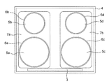
- FIG. 1 is a plan view showing the appearance of the induction heating cooker according to the first embodiment of the present invention, and shows a top plate 1 provided on the upper part of the main body.
- the lower position is a position where the user is present, and the operation display unit 3 is provided on the front side of the top plate 1 which is the user side.
- the top plate 1 shown in FIG. 1 is formed of heat resistant glass, for example, crystallized glass.
- four circle patterns 2a, 2b, 2c, and 2d that indicate the heating positions on which an object to be heated (a cooking container such as a pan) is placed are drawn.
- 2c indicates a position corresponding to an induction heating coil having a maximum output of 3 kW
- circle patterns 2b and 2d having a small diameter indicate positions corresponding to an induction heating coil having a maximum output of 2 kW, for example.
- FIG. 2 is a plan view showing the main body of the induction heating cooker according to the first embodiment in a state where the top plate 1 shown in FIG. 1 is removed.
- an outer case 4 is provided on the main body, and the top plate 1 is supported by the outer case 4.
- Inductive heating coils 5a, 5b, 5c, and 5d are provided immediately below the circle patterns 2a, 2b, 2c, and 2d drawn on the top plate 1, respectively.
- Each induction heating coil 5a, 5b, 5c, 5d is fixed to a heating coil base 6a, 6b, 6c, 6d made of an insulating material such as a resin.
- the heating coil bases 6a, 6b, 6c, 6d are provided with ferrite (not shown) for passing magnetic flux generated from the induction heating coils 5a, 5b, 5c, 5d.
- heating coil bases 6a and 6b to which induction heating coils 5a and 5b arranged on the left side as viewed from the user are fixed are supported by a first support plate 7a formed of aluminum metal. Yes.
- the heating coil bases 6c and 6d to which the induction heating coils 5c and 5d arranged on the right side as viewed from the user are fixed are similarly supported by a second support plate 7b made of aluminum metal.
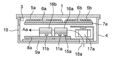
- FIG. 3 is a cross-sectional view of the main part cut along line III-III of the induction heating cooker shown in FIG. 1
- FIG. 4 is a cross-sectional view of the main part cut along line IV-IV of the induction heating cooker shown in FIG. FIG.
- an induction heating coil 5a having a high output for example, a maximum output of 3 kW
- an induction heating coil 5b having a low output for example, a maximum output of 2 kW
- the inner side of the main body of the induction heating cooker is shown.
- FIG. 4 shows that high-power induction heating coils 5a and 5c are arranged side by side.
- the first inverter circuit board 8a for supplying high-frequency current to the induction heating coils 5a and 5b arranged on the left side when viewed from the user is a first support plate 7a that supports the heating coil bases 6a and 6b. And is fixed to a first substrate base 9a made of resin.
- the second inverter circuit board 8b for supplying high-frequency current to the induction heating coils 5c and 5d arranged on the right side when viewed from the user is a second support for supporting the heating coil bases 6c and 6d. It is disposed under the plate 7b and is fixed to a second substrate base 9b made of resin.
- the first substrate base 9 a and the second substrate base 9 b are fixed to the outer case 4.
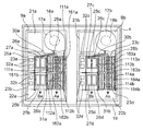
- FIG. 5 shows parts related to the cooling mechanism in the outer case 4 by removing the top plate 1 and parts such as the induction heating coils 5a, 5b, 5c, and 5d in the induction heating cooker of the first embodiment.
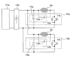
- FIG. FIG. 6 is a circuit diagram showing a main configuration of an inverter circuit for supplying a high-frequency current to induction heating coils 5a and 5b in the induction heating cooker according to the first embodiment.
- the switching element, the rectifier, and the air inlet are in hidden positions, and the positions are indicated by broken lines.
- the first inverter circuit board 8a that supplies a high-frequency current to the induction heating coils 5a and 5b arranged on the left side as viewed from the user will be described.
- the first inverter circuit board 8a arranged in the left region of the outer case 4 has a high output inverter circuit 10a as a first inverter circuit and a low output inverter circuit 10b as a second inverter circuit.
- the high-power inverter circuit 10a which is a first inverter circuit, includes a switching element 11a, and a first passive unit 14a that includes a resonance capacitor 12a and a smoothing capacitor 13a.
- the low-power inverter circuit 10b which is the second inverter circuit, includes a switching element 11b, and a second passive portion 14b composed of a resonant capacitor 12b and a smoothing capacitor 13b.
- the power from the first power circuit board 21a is rectified by the rectifier 15a and supplied to each of the high output inverter circuit 10a and the low output inverter circuit 10b.
- the same first cooling fin 16a is attached to the switching element 11a and the rectifier 15a indicated by a broken line in FIG. 5, and is configured to cool heat generated during operation.
- the switching element 11b shown with a broken line in FIG. 5 is attached to the 2nd cooling fin 16b which is a different body from the 1st cooling fin 16a.
- a first cooling blower 17a which is a first cooling unit, is provided in the vicinity of the first cooling fins 16a.
- the cooling fin 16a is disposed immediately before the outlet 33a of the first cooling blower 17a.
- the 1st cooling fin 16a has the structure which receives the cooling air from the blower outlet 33a of the 1st cooling blower 17a directly, and is cooled.
- the first cooling blower 17a sucks outside air from a first intake port 18a (see FIGS. 3 and 5) formed on the lower surface of the main body, and enters the high-output inverter circuit 10a in the first inverter circuit board 8a. It is arranged to send cooling air directly.
- the first cooling blower 17a is configured to blow cooling air to the high output inverter circuit 10a and to blow the cooling air after blowing to the high output inverter circuit 10a to the low output inverter circuit 10b.
- the wind after being blown to the low output inverter circuit 10b is exhausted to the outside of the main body through an exhaust port 19 (see FIGS. 3 and 5) having a large opening and low ventilation resistance.
- the high-power inverter circuit 10a is disposed at a position close to the first intake port 18a through which cooler outside air is sucked than the low-power inverter circuit 10b, and the high-power inverter circuit 10a is cooled.
- the cooled wind cools the low-power inverter circuit 10b.
- the cooling air blown from the outlet 33a of the first cooling blower 17a in the induction heating cooker of the first embodiment is changed from the rear side (upper side in FIG. 5) to the front side (lower side in FIG. 5).
- the ink is discharged so as to have a flow substantially parallel to the direction, and is formed so as to have a substantially linear flow in the main body.
- the first inverter in which the high-output inverter circuit 10a that is the first inverter circuit and the low-output inverter circuit 10b that is the second inverter circuit are mounted.
- the circuit board 8a is cooled by the first cooling blower 17a.
- the first cooling fin 16a to which the rectifier 15a and the switching element 11a of the high output inverter circuit 10a are attached, and the switching element 11b of the low output inverter circuit 10b are attached.
- the second cooling fins 16b are arranged in a column along the flow of cooling air from the first cooling blower 17a (in the direction of arrow Aa in FIG. 5).
- the second cooling fin 16b to which the switching element 11b of the low-power inverter circuit 10b is attached is disposed at a position for receiving the cooling air that has passed through the first cooling fin 16a to which the rectifier 15a and the switching element 11a are attached. ing.
- the 1st cooling fin 16a and the 2nd cooling fin 16b which were used in the induction heating cooking appliance of Embodiment 1 have the same shape and the same dimension, and the cross section orthogonal to the direction of the flow of cooling air
- the shape is the same. That is, the first cooling fin 16a and the second cooling fin 16b have a plurality of fins parallel to the direction of the cooling air flow, and the cross-sectional shape orthogonal to the direction of the cooling air flow is a so-called comb. It is in the shape.
- the first cooling fins 16a and the second cooling fins 16b are formed by extrusion molding of an aluminum material. Further, in the induction heating cooker of the first embodiment, the fins in the first cooling fins 16a are arranged at positions corresponding to the fins in the second cooling fins 16b, and the ventilation resistance is greatly suppressed.
- the first passive portion 14a composed of the resonance capacitor 12a and the smoothing capacitor 13a in the high-output inverter circuit 10a, and the resonance capacitor 12b and the smoothing capacitor 13b in the low-output inverter circuit 10b.
- the second passive portion 14b of the low output inverter circuit 10b is arranged at a position for receiving the cooling air that has passed through the first passive portion 14a of the high output inverter circuit 10a.
- the high-power inverter circuit 10a is provided with two heating coil terminals 20a, and the heating coil terminal 20a and the induction heating coil 5a (maximum output 3 kW) provide lead wires (not shown). Is electrically connected.
- the low output inverter circuit 10b is also provided with two heating coil terminals 20b, and the heating coil terminal 20b and the induction heating coil 5b (maximum output 2 kW) are electrically connected via a lead wire (not shown). It is connected to the.
- the heating coil terminal 20a and the induction heating coil 5a, and the heating coil terminal 20b and the induction heating coil 5b are connected, and the high-frequency current formed in each inverter circuit 10a, 10b is applied to each induction heating coil 5a, 5b. Have been supplied.
- a first power supply circuit board 21a configured with a power supply circuit for supplying power to the first inverter circuit board 8a is disposed in the vicinity of the position where the first cooling blower 17a is provided.
- the cooling air is provided at a position where the cooling air from the outlet 33a of the cooling blower 17a is not directly applied. That is, the first power circuit board 21a is disposed at the back side (upper side in FIG. 5) of the outer case 4 and is arranged in parallel with the first cooling blower 17a disposed at the back side of the outer case 4.
- the blower outlet 33a of the 1st cooling blower 17a is arrange
- the second inverter circuit board 8b disposed on the right side of the outer case 4 is provided with a high output inverter circuit 10c as a first inverter circuit and a low output inverter circuit 10d as a second inverter circuit.
- a high-power inverter circuit 10c which is a first inverter circuit, includes a switching element 11c, and a third passive portion 14c configured by a resonant capacitor 12c and a smoothing capacitor 13c.
- the low-power inverter circuit 10d which is the second inverter circuit, includes a switching element 11d, and a fourth passive portion 14d configured by a resonance capacitor 12d and a smoothing capacitor 13d.
- the power from the second power circuit board 21b is rectified in the rectifier 15b as in the first inverter circuit board 8a shown in FIG. It is supplied to each of the circuit 10c and the low output inverter circuit 10b.
- the switching element 11c and the rectifier 15b indicated by a broken line in FIG. 5 are attached to the same third cooling fin 16c and configured to cool heat generated during operation. Further, the switching element 11d indicated by a broken line in FIG. 5 is attached to a fourth cooling fin 16d that is a separate body from the third cooling fin 16c.
- a second cooling blower 17b which is a second cooling unit as a cooling means, is provided in the vicinity of the third cooling fin 16c.
- the third cooling fin 16c is disposed immediately before the outlet 33b of the second cooling blower 17b. For this reason, the 3rd cooling fin 16c has the structure which receives the cooling air from the blower outlet 33b of the 2nd cooling blower 17b directly.
- the second cooling blower 17b sucks outside air from a second intake port 18b (see FIG. 5) formed on the lower surface of the main body, and directly enters the high-power inverter circuit 10c in the second inverter circuit board 8b. Arranged to send cooling air.
- the second cooling blower 17b is configured to blow cooling air to the high output inverter circuit 10c and to blow the cooling air blown to the high output inverter circuit 10c to the low output inverter circuit 10d. After being blown to the low output inverter circuit 10d, the wind is exhausted out of the main body through an exhaust port 19 (see FIG. 5) having a large opening and a small ventilation resistance.
- the high-power inverter circuit 10c is disposed at a position close to the second intake port 18b through which cooler outside air is sucked than the low-power inverter circuit 10d, thereby cooling the high-power inverter circuit 10c.
- the cooled wind cools the low-power inverter circuit 10d.
- the cooling air blown from the outlet 33b of the second cooling blower 17b in the induction heating cooker of the first embodiment is changed from the rear side (upper side in FIG. 5) to the front side (lower side in FIG. 5).
- the ink is discharged so as to have a flow substantially parallel to the direction, and is formed so as to have a substantially linear flow in the main body.
- the second inverter in which the high output inverter circuit 10c that is the first inverter circuit and the low output inverter circuit 10d that is the second inverter circuit are mounted.
- the circuit board 8b is cooled by the second cooling blower 17b. Therefore, in the second inverter circuit board 8b, the third cooling fin 16c to which the rectifier 15b and the switching element 11c of the high output inverter circuit 10c are attached, and the switching element 11d of the low output inverter circuit 10d are attached.
- the fourth cooling fins 16d are arranged in a column along the flow of cooling air from the second cooling blower 17b (in the direction of arrow Ab in FIG. 5).
- the fourth cooling fin 16d to which the switching element 11d of the low-power inverter circuit 10d is attached is disposed at a position for receiving the cooling air that has passed through the third cooling fin 16c to which the rectifier 15b and the switching element 11c are attached. ing.
- the 3rd cooling fin 16c and the 4th cooling fin 16d used in the induction heating cooking appliance of Embodiment 1 are the same shape similarly to the above-mentioned 1st cooling fin 16a and the 2nd cooling fin 16b. Have the same dimensions and the same cross-sectional shape perpendicular to the flow direction of the cooling air. That is, like the first cooling fin 16a and the second cooling fin 16b, the third cooling fin 16c and the fourth cooling fin 16d have a plurality of fins parallel to the flow direction of the cooling air.
- the cross-sectional shape orthogonal to the flow direction of the cooling air is a so-called comb shape.
- the third cooling fin 16c and the fourth cooling fin 16d are formed by extrusion molding of an aluminum material. Further, in the induction heating cooker of the first embodiment, the fins in the third cooling fins 16c are arranged at positions corresponding to the fins in the fourth cooling fins 16d, and the ventilation resistance is greatly suppressed.
- the third passive portion 14c constituted by the resonance capacitor 12c and the smoothing capacitor 13c in the high output inverter circuit 10c, and the resonance capacitor 12d and the smoothing capacitor 13d in the low output inverter circuit 10d.
- the fourth passive portion 14d of the low-power inverter circuit 10d is arranged at a position for receiving the cooling air that has passed through the third passive portion 14c of the high-power inverter circuit 10c.
- the high-power inverter circuit 10c is provided with two heating coil terminals 20c, and the heating coil terminal 20c and the induction heating coil 5c (maximum output 3 kW) provide lead wires (not shown). Is electrically connected.
- the low-power inverter circuit 10d is also provided with two heating coil terminals 20d, and the heating coil terminal 20d and the induction heating coil 5d (maximum output 2 kW) are electrically connected via a lead wire (not shown). It is connected to the.
- the heating coil terminal 20c and the induction heating coil 5c, and the heating coil terminal 20d and the induction heating coil 5d are connected, and the high-frequency current formed in each of the inverter circuits 10c and 10d is supplied to the induction heating coils 5c and 5d. Have been supplied.
- the second power supply circuit board 21b in which the power supply circuit for supplying power to the second inverter circuit board 8b is configured is disposed in the vicinity of the position where the second cooling blower 17b is provided.
- the cooling air is provided at a position where the cooling air from the outlet 33b of the cooling blower 17b does not directly hit. That is, the second power circuit board 21b is disposed at a position on the back side (upper side in FIG. 5) of the outer case 4 and is arranged in parallel with the second cooling blower 17b disposed on the rear side of the outer case 4.
- the blower outlet 33b of the 2nd cooling blower 17b is arrange
- the user places an object to be heated, which is a cooking container such as a pan, on the circle patterns 2a and 2b indicating the heating unit on the top plate 1 of the induction heating cooker according to the first embodiment.
- Set the heating conditions in step 3. For example, in the operation display unit 3, the user turns on the heating switches of the induction heating coils 5a and 5b corresponding to the circle patterns 2a and 2b.
- the high output inverter circuit 10a and the low output inverter circuit 10b in the first inverter circuit board 8a are activated, and a desired high-frequency current is formed.
- the high frequency currents formed in the high output inverter circuit 10a and the low output inverter circuit 10b are supplied to the induction heating coils 5a and 5b corresponding to the respective circle patterns 2a and 2b via the heating coil terminals 20a and 20b. Is done. As a result, a high frequency magnetic field is generated from the induction heating coils 5a and 5b, and an object to be heated such as a pot placed on the circle patterns 2a and 2b is induction heated.
- the high-frequency current output from the heating coil terminal 20a of the high-power inverter circuit 10a in the first inverter circuit board 8a is composed of the switching element 11a, the resonance capacitor 12a, and the smoothing capacitor 13a. It is formed in the first passive portion 14a and the like.
- the high-frequency current output from the heating coil terminal 20b of the low-power inverter circuit 10b in the first inverter circuit board 8a is a switching element 11b, and a second passive portion 14b composed of a resonant capacitor 12b and a smoothing capacitor 13b. Etc. are formed.
- high-frequency current forming components such as the switching elements 11a and 11b, the resonance capacitors 12a and 12b, and the smoothing capacitors 13a and 13b generate heat.
- the cooling fins 16a and 16b are attached to the switching elements 11a and 11b that generate a particularly large amount of heat, thereby improving the heat dissipation performance.
- the first cooling blower 17a is driven during the induction heating operation, and the high-power inverter circuit is configured such that the outside air sucked from the first intake port 18a serves as cooling air.
- the low power inverter circuit 10b is sprayed in order from 10a.
- the cooling air flowing in this way is exhausted to the outside of the main body from the exhaust port 19 having a large opening and a shape with a small ventilation resistance.
- the cooling air from the first cooling blower 17a is efficiently applied to the heat generating components in the inverter circuits 10a and 10b, and the heat generating components are efficiently cooled. It is operating.
- the cooling air closer to the outlet 33a of the first cooling blower 17a is the cooling air farther from the outlet 33a (the cooling on the arrow Ba side).
- the air volume is larger than (wind). That is, the cooling air (cooling air on the arrow Aa side) that flows through the air passage space facing the air outlet 33a of the first cooling blower 17a is cooled by the cooling air (the arrow Ba side) that flows in the air passage space that is separated from the air outlet 33a.
- Air volume is larger than cooling air).
- the air passage space that faces the air outlet is a space that opposes the opening surface of the air outlet of the cooling blower, and the air passage that has the same cross section as the air outlet opening surface in the direction that the cooling air flows. It is space.
- a second cooling fin 16b for cooling the switching element 11b in 10b is provided. Further, the first cooling fins 16a are arranged on the windward side of the second cooling fins 16b, and the first cooling fins 16a and the second cooling fins 16b are arranged in tandem.
- a first passive portion 14a in the high-power inverter circuit 10a and a second passive portion 14b in the low-power inverter circuit 10b are provided in the air passage space that is removed from the outlet 33a of the first cooling blower 17a. Furthermore, the 1st passive part 14a is arrange
- the first cooling fins 16a and the second cooling fins 16b having a large heat radiation amount are arranged in the air passage space facing the blowout port 33a of the first cooling blower 17a, and the first cooling fins 16a are disposed.
- the 2nd cooling fin 16b is comprised so that it may be cooled with the cooling air (cooling air shown by arrow Aa of FIG. 5) with many airflows.
- the first passive portion 14a and the second passive portion 14b having a relatively small amount of heat radiation are arranged in the air passage space that is out of the blowout port 33a of the first cooling blower 17a, and the cooling air ( The cooling is performed by cooling air indicated by an arrow Ba in FIG.
- the induction heating cooker according to the first embodiment configured as described above efficiently cools the first inverter circuit board 8a arranged in consideration of the amount of heat generated by one cooling blower 17a. Can do.
- the cooling capacity is adjusted with respect to the outlet 33a of the first cooling blower 17a (for example, the first cooling fin 16a, the first cooling fin 16a, and the like).
- the adjustment can be easily made.
- the first cooling blower 17a cools the cooling fins 16a and 16b and the passive portions 14a and 14b provided on the first inverter circuit board 8a.
- the second cooling blower 17b disposed on the right side of the outer case 4 is also applied to the cooling fins 16c and 16d and the passive portions 14c and 14d provided on the second inverter circuit board 8b.
- the high-power inverter circuits 10a and 10c are cooled, and the low-power inverter circuits 10b and 10d are used by using the cooling air that has cooled the high-power inverter circuits 10a and 10c. It can be used for cooling. Therefore, the induction heating cooker according to the first embodiment can efficiently use the cooling air from the cooling blowers 17a and 17b without waste. As a result, the cooling blowers 17a and 17b can be reduced in size and noise. It is the structure which demonstrates a big effect on.
- the cooling fins 16a and 16c of the high output inverter circuits 10a and 10c and the cooling fins 16b and 16d of the low output inverter circuits 10b and 10d are separated and separated. It is configured. For this reason, the heat generation (loss heat) of the switching elements 11a and 11c of the high output inverter circuits 10a and 10c and the heat generation (loss heat) of the switching elements 11b and 11d of the low output inverter circuits 10b and 10d directly form the cooling fins.
- the switching elements 11a, 11b, 11c, and 11d are reliably cooled by the cooling fins 16a, 16b, 16c, and 16d without being affected by heat conduction.
- the switching mounted on the cooling fins 16a, 16b, 16c, and 16d is performed. It is not necessary to consider the insulation state for the elements 11a, 11b, 11c, and 11d. That is, in the induction heating cooker of the first embodiment, an insulator is inserted between each of the switching elements 11a, 11b, 11c, and 11d and the cooling fins 16a, 16b, 16c, and 16d to electrically connect each other. There is no need to insulate.
- the insulator which worsens thermal conductivity between each of switching element 11a, 11b, 11c, 11d and cooling fin 16a, 16b, 16c, 16d, For example, an insulating sheet or the like is unnecessary, and as a result, the cooling performance is greatly improved.
- the surface on which the cooling fin is attached has the same potential as the collector.
- the cooling fin When the cooling fin is directly attached to such a switching element, the cooling fin has the same potential as the collector of the switching element.
- some switching elements include a type in which an insulator is provided inside the cooling fin mounting surface (heat radiation surface), and the cooling fin mounting surface (heat radiation surface) is previously insulated from the collector.
- the heat conduction performance is reduced due to the influence of the insulator provided in the heat radiation surface of the switching element, and cooling Has the problem of poor performance.
- the induction heating cooker according to the first embodiment not the insulating type switching element but the switching element whose cooling fin mounting surface (heat radiation surface) is the collector potential is used, and the cooling performance of the switching element itself is improved. It is the structure which prevents the fall.
- the first cooling fins 16a and the second cooling fins 16b are adapted to the substantially linear cooling air flow from the first cooling blower 17a.
- the orthogonal cross-sectional shapes are the same, and a plurality of fins protruding from the first cooling fins 16a and the second cooling fins 16b are arranged in parallel to the flow of the cooling air.
- the second cooling fins 16b are arranged in a tandem state at the leeward position of the first cooling fins 16a along a substantially linear cooling air flow from the first cooling blower 17a. .
- the pressure loss of the cooling air that has passed through the first cooling fin 16a and the second cooling fin 16b is small, and the cooling performance is improved.
- This point is similarly formed and arranged in the third cooling fin 16c and the fourth cooling fin 16d with respect to the second cooling blower 17b, and has the same effect.
- the cooling fins 16a, 16b, 16c, and 16d have the same cross-sectional shape and can be drawn, so that a mold or the like can be shared.
- productivity can be improved and manufacturing costs can be reduced.
- the high output inverter circuits 10a and 10c are arranged in the vicinity of the cooling blowers 17a and 17b, and are arranged on the windward side of the low output inverter circuits 10b and 10d.
- the inverter circuits 10a and 10c are configured such that cooling air having a low temperature and a high wind speed is blown from the intake ports 18a and 18b.
- the cooling performance for the high output inverter circuits 10a and 10c is set higher than the cooling performance for the low output inverter circuits 10b and 10d.
- the induction heating coils 5a and 5c having a maximum output of 3 kW have a high frequency current.
- the high-power inverter circuits 10a and 10c that supply high-frequency current and the low-power inverter circuits 10b and 10d that supply high-frequency current to the induction heating coils 5b and 5d having a maximum output of 2 kW can be efficiently air-cooled with appropriate cooling performance. .
- the near side is more convenient for the user, as shown in FIG. 2, in the near side area, that is, in the area close to the operation display unit 3, for example, By arranging the induction heating coils 5a and 5c having a maximum output of 3 kW and arranging the induction heating coils 5b and 5d having a maximum output of 2 kW, for example, in the back region, the convenience of the user is improved. Can do.
- the inverter circuit boards 8a and 8b in the outer case 4 the low output inverter circuits 10b and 10d are disposed in the front area, and the high output inverter circuit is disposed in the rear area. 10a and 10c are arranged.
- the arrangement of the high output inverter circuits 10a, 10c and the low output inverter circuits 10b, 10d is opposite to the arrangement of the induction heating coils 5a, 5b, 5c, 5d.
- the output arrangement of the inverter circuit boards 8a and 8b and the output arrangement of the induction heating coils 5a, 5b, 5c and 5d can be easily changed. Electrical connection between them can be easily performed.
- the rectifiers 15a and 15b that supply DC power to the high-output inverter circuits 10a and 10c and the low-output inverter circuits 10b and 10d are shared, and the rectifiers 15a and 15b are shared.
- the switching elements 11a and 11c of the high output inverter circuits 10a and 10c are mounted on the cooling fins 16a and 16c, respectively.
- one rectifier 15a (or 15b) has a shared configuration for supplying power to the high-power inverter circuit 10a (or 10c) and the low-power inverter circuit 10b (or 10d), the components in the inverter circuit boards 8a and 8b And the wiring pattern can be reduced, and the circuit area can be greatly reduced.
- the rectifier 15a provided on the first inverter circuit board 8a is mounted on the first cooling fin 16a together with the switching element 11a to be cooled.
- the first cooling fin 16a is provided immediately before the outlet 33a of the first cooling blower 17a, and is located closer to the first cooling blower 17a than the second cooling fin 16b, so that the cooling performance is high. It has become. For this reason, even if the switching element 11a and the rectifier 15a are both attached to the first cooling fin 16a, it is possible to cope with the same size of the first cooling fin 16a and the second cooling fin 16b.
- the cooling performance of the first cooling fins 16a is enhanced, it is not necessary to form them extremely larger than the second cooling fins 16b. As a result, the occupied area in the inner space of the outer case 4 of the first inverter circuit board 8a can be reduced. Further, since the rectifier 15a is attached to the first cooling fin 16a, the rectifier 15a is reliably cooled and can exhibit a highly reliable rectification function. The same can be said for the rectifier 15b provided on the second inverter circuit board 8b.
- the rectifier 15a is supplied to the rectifier 15a from the first power supply circuit board 21a.
- the rectifier 15a and the first power supply circuit board 21a are arranged at close positions. Yes.
- the rectifier 15a is arranged at a position closest to the outlet 33a of the first cooling blower 17a in the first inverter circuit board 8a in the vicinity of the first cooling blower 17a arranged on the back side in the outer case 4.
- the first power circuit board 21 a is arranged in parallel with the first cooling blower 17 a on the back side of the outer case 4.
- the wiring of the alternating current power supply which connects the 1st power supply circuit board 21a and the rectifier 15a on the 1st inverter circuit board 8a can be shortened.
- the AC power supply wiring connecting the second power circuit board 21b and the rectifier 15b on the second inverter circuit board 8b is shortened. be able to.
- the first power circuit board 21a is arranged next to the first cooling blower 17a, and the cooling air from the first cooling blower 17a is used as the first power supply. It is arranged at a position where it does not directly hit the circuit board 21a.
- the first power supply circuit board 21a that has few heat generating parts and does not need to be actively cooled is cooled next to the first cooling blower 17a. They can be placed in areas that are not exposed to wind.
- the second power circuit board 21b can be arranged next to the second cooling blower 17b in a region where the cooling air does not hit, the space in the outer case 4 can be used effectively.
- the main body can be reduced in size and thickness, and wiring from the power supply circuit boards 21a and 21b to the inverter circuit boards 8a and 8b can be achieved. Can be configured efficiently and in order.
- a lead-out portion for a power cord (not shown) for taking in an external power source is provided on the back side (back side as viewed from the user) of the main body, and the power cord is electrically connected to the power circuit boards 21a and 21b. It becomes a structure easy to connect to. Further, it is easy to supply power from the power supply circuit board 21a, 21b to the inverter circuit boards 8a, 8b and the cooling blowers 17a, 17b, etc., and the heating coil terminals 20a, 20b, 20c of the inverter circuit boards 8a, 8b.
- common power supply circuit boards 21a and 21b are provided as power supply circuits for the high output inverter circuits 10a and 10c and the low output inverter circuits 10b and 10d. Therefore, the maximum value (for example, 3 kW) of the total output of the outputs of the high output inverter circuits 10a and 10c (maximum output is 3 kW) and the outputs of the low output inverter circuits 10b and 10d (maximum output is 2 kW) is set in advance.
- the respective outputs of the high output inverter circuits 10a and 10c and the low output inverter circuits 10b and 10d can be distributed in a desired ratio. For example, when the user wants to increase the output of the high output inverter circuit 10a, the output of the low output inverter circuit 10b is set small. Such setting and control are performed in a control circuit which is a control unit provided on the power circuit board.
- the performance of the first cooling blower 17a can be reduced to reduce the size, and the first The size of the cooling fin in the inverter circuit board 8a can be reduced.
- the first cooling blower 17a and the second cooling blower 17b used in the induction heating cooker according to the first embodiment have a plurality of blades arranged substantially radially along the circumferential surface of the cylinder.
- the cylindrical shape has intake ports 18a and 18b on one end surface portion on the rotation center axis thereof.
- the first cooling blower 17a and the second cooling blower 17b configured as described above are configured so that the inner periphery of the cylindrical case that covers the blades by rotating the cylinder and moving the blades along the circumferential surface. In this structure, air flows along the surface and air is discharged from the outlets 33a and 33b.
- the cooling air from the first cooling blower 17a and the second cooling blower 17b is blown out from the outlets 33a and 33b with a substantially uniform air volume.
- the air volume on the outer peripheral side may be slightly increased. In that case, you may mount so that the centerline of the heat-emitting component which should be cooled may be arrange
- the induction heating apparatus balances the amount of cooling air with respect to the heat radiation members arranged in parallel, which has been a problem in the configuration of the above-described conventional induction heating cooker. There is no need to take it, and it has an excellent effect that the cooling design becomes easy and the cooling performance itself is improved. That is, the cooling fin with the switching element mounted generally has a larger amount of heat generation than a heat-generating mounting component (passive part) that is directly mounted on a substrate such as a resonance capacitor or a smoothing capacitor.
- the fin region and the mounting component region are roughly divided and arranged in two systems to be cooled by the cooling blower (17a, 17b).
- the cooling blower (17a, 17b) When the air is blown to the high-output and low-output inverter circuits (10a, 10b, 10c, 10d), it is easy to adjust the air volume balance so that a large air volume flows in the fin area and a small air volume flows in the mounted component area.
- the structure which cools a high output inverter circuit (10a, 10c) and a low output inverter circuit (10b, 10d) with sufficient balance can be designed easily. Moreover, since the cooling air that has cooled the high-power inverter circuits (10a, 10c) can be used as it is for cooling the low-power inverter circuits (10b, 10d), there is no waste of cooling air, and consequently the cooling blower Great effect for miniaturization and noise reduction.
- the fins in the switching elements of the high output inverter circuits (10a, 10c) and the switching elements (11b, 11d) of the low output inverter circuits (10b, 10d) Since the potentials of the mounting surfaces are different, it is necessary to take measures such as insulation for the switching element when the metallic cooling fin is used in common.
- the switching element and the cooling fin It is not necessary to consider the insulation between them, and for example, measures such as inserting an insulator, for example, an insulating sheet, between the switching element and the cooling fin become unnecessary. Providing an insulator such as an insulating sheet between the switching element and the cooling fin deteriorates the heat conduction between them and lowers the cooling performance.
- the independent cooling fin is provided for each switching element, it is not necessary to provide an insulator between the switching element and the cooling fin, resulting in improved cooling performance. It is the composition which makes it.
- the induction heating cooker of Embodiment 2 is demonstrated using FIGS. 7-10 as an example of the induction heating apparatus of this invention.
- the induction heating cooker according to the second embodiment is different from the induction heating cooker according to the first embodiment in the number of switching elements in the inverter circuit that supplies a high-frequency current to the induction heating coil.
- the switching element of the inverter circuit is composed of two switching elements on the positive electrode side and the switching element on the negative electrode side for one induction heating coil. Therefore, in the description of the induction heating cooker of the second embodiment, the components having substantially the same function and configuration as those of the induction heating cooker of the first embodiment are given the same reference numerals, The description is omitted.
- the induction heating cooker according to the second embodiment has substantially the same appearance as the induction heating cooker according to the first embodiment described with reference to FIGS. 1 and 2 described above. Heating coils 5a and 5b are arranged, and induction heating coils 5c and 5d are arranged on the right side when viewed from the user.
- FIG. 7 shows the main parts on the near side (left side in FIG. 7) and the back side (right side in FIG. 7) as seen from the user in the induction heating cooker according to the second embodiment, as in FIG. It is sectional drawing cut
- FIG. 7 shows an induction heating coil 5a having a high output (for example, a maximum output of 3 kW) and an induction heating coil 5b having a low output (for example, a maximum output of 2 kW).
- An arrangement of cooling blowers as cooling means is shown on the back side of the main body.
- FIG. 8 is a cross-sectional view taken along the left and right main parts of the user in the induction cooking device of the second embodiment, similarly to FIG. In the induction heating cooker of Embodiment 2 shown in FIG. 8, it is shown that the high output induction heating coils 5a and 5c are arranged side by side.
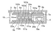
- FIG. 9 shows parts related to the cooling mechanism in the outer case 4 by removing parts such as the top plate 1 and the induction heating coils 5a, 5b, 5c, and 5d in the induction heating cooker of the second embodiment.
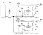
- FIG. 10 is a circuit diagram showing a main configuration of an inverter circuit for supplying high-frequency current to induction heating coils 5a and 5b in the induction heating cooker according to the second embodiment. In the components and configurations related to the cooling mechanism shown in FIG.
- the induction heating cooker of the second embodiment is for supplying a high-frequency current to the induction heating coils 5a and 5b arranged on the left side when viewed from the user.
- the first inverter circuit board 22a is disposed under the first support plate 7a that supports the heating coil bases 6a and 6b, and is fixed to the first board base 9a formed of resin ( (See FIG. 8).
- the second inverter circuit board 22b for supplying high-frequency current to the induction heating coils 5c and 5d arranged on the right side when viewed from the user is a second support for supporting the heating coil bases 6c and 6d. It is disposed under the plate 7b and is fixed to a second substrate base 9b made of resin (see FIG. 8).
- the first substrate base 9 a and the second substrate base 9 b are fixed to the outer case 4.
- the first inverter circuit board 22a that supplies a high-frequency current to the induction heating coils 5a and 5b arranged on the left side when viewed from the user, and the first inverter circuit board 22a are cooled. This relates to the configuration and operation of the first cooling blower 17a for sending the wind.
- the first inverter circuit board 22a disposed in the left region of the outer case 4 has a high output inverter circuit 23a as a first inverter circuit and a low output inverter circuit 23b as a second inverter circuit.
- the high-power inverter circuit 23a includes two switching elements 111a and 111b, and a first passive unit 27a including a resonance capacitor 25a and a smoothing capacitor 26a.
- the low-power inverter circuit 23b includes two switching elements 112a and 112b, and a second passive unit 27b including a resonance capacitor 25b and a smoothing capacitor 26b.
- the power from the first power circuit board 21a is rectified by a rectifier 28a, and a high output inverter circuit 23a as a first inverter circuit and a low output inverter circuit as a second inverter circuit. 23b is supplied to each.
- the same first cooling fin 161a is attached to the switching element 111a and the rectifier 28a indicated by broken lines in FIG. 9, and is configured to cool heat generated during operation.
- each of the switching elements 111b, 112a, and 112b indicated by broken lines in FIG. 9 includes a second cooling fin 161b, a third cooling fin 162a, and a fourth cooling fin that are separate from the first cooling fin 161a.
- the fins 162b are respectively attached.
- a duct 30a is provided at the outlet 33a of the first cooling blower 17a disposed on the back side of the outer case 4.
- the duct 30a is provided so as to surround the first inverter circuit board 22a, and includes a first cooling fin 161a, a second cooling fin 161b, a third cooling fin 162a, a fourth cooling fin 162b, Mounting components such as the first passive portion 27a and the second passive portion 27b are covered.
- One opening serving as the suction port of the duct 30a is attached to the blowout port 33a of the first cooling blower 17a, and the other opening serving as the exhaust port of the duct 30a generates heat in the first inverter circuit board 22a. It is provided immediately after covering the position where the mounting component is lost, for example, the fourth cooling fin 162b.
- the duct 30a is provided as described above, and the distribution rib 31a is provided inside the duct 30a.
- the distribution rib 31a includes a fin region in which the first cooling fin 161a, the second cooling fin 161b, the third cooling fin 162a, and the fourth cooling fin 162b are disposed, The portion between the passive part 27a and the mounting component area where the second passive part 27b is arranged is divided.
- the duct 30a and the distribution rib 31a are provided, the cooling air from the outlet 33a of the first cooling blower 17a is reliably distributed to the fin region and the mounted component region.
- the fin region and the mounted component region follow the flow of the cooling air, that is, the back of the outer case 4 It is divided along the direction from the side to the near side, and each area is divided into left and right.
- the cooling fin 161a, 161b, 162a, 162b, 163a, 163b in each inverter circuit 23a, 23b, 23c, 23d of high output and low output A region where 164a and 164b are arranged is called a fin region, and a region where a resonance capacitor which is a heat-generating mounting component mounted on a substrate and generates heat during operation and a passive part having a smoothing capacitor are arranged is called a mounting component region.
- a first cooling blower 17a is provided in the vicinity of the first cooling fin 161a, and the first cooling fin 161a is the first cooling fin 161a. It is disposed immediately before the outlet 33a of the cooling blower 17a. For this reason, the first cooling fin 161a has a structure for directly receiving the cooling air distributed by the duct 30a and the distribution rib 31a from the outlet 33a of the first cooling blower 17a.
- the first cooling blower 17a sucks outside air from a first air inlet 18a (see FIGS. 7 and 9) formed on the lower surface of the main body, discharges cooling air from the air outlet 33a, and distributes the air to the duct 30a.
- the cooling air distributed by the ribs 31a is disposed so as to directly blow the high-power inverter circuit 23a in the first inverter circuit board 22a.
- the cooling air distributed from the first cooling blower 17a is blown to the high output inverter circuit 23a, and the cooling air blown to the high output inverter circuit 23a is blown to the low output inverter circuit 23b. ing.
- the wind after being blown to the low output inverter circuit 23b is exhausted to the outside of the main body through the exhaust port 19 (see FIGS. 7 and 9) having a large opening and a small ventilation resistance.
- the cooling air blown out from the outlet 33a of the first cooling blower 17a in the induction heating cooker of the second embodiment and distributed by the duct 30a and the distribution rib 31a is substantially in the direction from the back side to the front side in the main body. It is discharged so as to have a parallel flow, and is formed so as to have a substantially linear flow.
- the cooling air from the first cooling blower 17a is divided into the fin region and the mounting component region by the distribution rib 31a in the duct 30a, and most of the discharge air amount, for example, 80% of the cooling air flows into the fin region (the direction indicated by the arrow Aa in FIG. 9), and the first cooling fin 161a, the second cooling fin 161b, the third cooling fin 162a, and the fourth cooling fin 162b Cooling. Further, the cooling air of the remaining air volume flows into the mounting component region (the direction indicated by the arrow Ba in FIG. 9), and the first passive portion 27a and the second passive portion 27b are cooled.
- the first cooling fin 161a and the second cooling fin 161b of the high output inverter circuit 23a, and the third cooling fin 162a and the fourth cooling fin 162b of the low output inverter circuit 23b are the first It arrange
- the second cooling fin 161b with the switching element 111b attached is arranged at a position for receiving the cooling air that has passed through the first cooling fin 161a with the rectifier 28a and the switching element 111a attached thereto.
- a position where the third cooling fin 162a with the switching element 112a mounted is arranged at a position for receiving the cooling air that has passed through the second cooling fin 161b, and a position for receiving the cooling air that has passed through the third cooling fin 162a.
- a fourth cooling fin 162b on which the switching element 112b is mounted is disposed.
- the first passive unit 27a composed of the resonance capacitor 25a and the smoothing capacitor 26a of the high-output inverter circuit 23a, and the resonance capacitor 25b and the smoothing capacitor 26b of the low-output inverter circuit 23b.
- the second passive portion 27b of the low output inverter circuit 23b is arranged at a position for receiving the cooling air that has passed through the first passive portion 27a of the high output inverter circuit 23a.
- the high-power inverter circuit 23a is provided with two heating coil terminals 32a, and the heating coil terminal 32a and the induction heating coil 5a (maximum output 3 kW) provide lead wires (not shown). Is electrically connected.
- the low power inverter circuit 23b is also provided with two heating coil terminals 32b, and the heating coil terminal 32b and the induction heating coil 5b (maximum output 2 kW) are electrically connected via a lead wire (not shown). It is connected to the.
- the heating coil terminal 32a and the induction heating coil 5a, and the heating coil terminal 32b and the induction heating coil 5b are connected, and the high-frequency current formed in each inverter circuit 23a, 23b is applied to each induction heating coil 5a, 5b. Have been supplied.
- the first power supply circuit board 21a on which the power supply circuit for supplying power to the first inverter circuit board 22a is configured is disposed in the vicinity of the position where the first cooling blower 17a is provided.
- the cooling blower 17a is provided at a position where it is not directly exposed to the cooling air. That is, the first power circuit board 21a is disposed at a position on the back side (upper side in FIG. 9) of the outer case 4 and is juxtaposed with the first cooling blower 17a disposed on the rear side of the outer case 4.
- the air outlet 33a of the first cooling blower 17a is disposed in the direction of the first inverter circuit board 22a disposed on the front side (lower side in FIG. 9) of the outer case 4, and the duct 30a and Distribution ribs 31a are provided.
- the second inverter circuit board 22b that supplies a high-frequency current to the induction heating coils 5c and 5d arranged on the right side when viewed from the user will be described.
- the second inverter circuit board 22b disposed on the right side of the outer case 4 is provided with a high output inverter circuit 23c as a first inverter circuit and a low output inverter circuit 23d as a second inverter circuit.
- the high output inverter circuit 23c includes two switching elements 113a and 113b, and a third passive unit 27c including a resonance capacitor 25c and a smoothing capacitor 26c.
- the low-power inverter circuit 10d includes a second passive unit 27d configured by two switching elements 114a and 114b, a resonant capacitor 25d, a smoothing capacitor 26d, and the like.
- the power from the second power circuit board 21b is rectified in the rectifier 28b as in the first inverter circuit board 22a shown in FIG. It is supplied to each of the circuit 23c and the low output inverter circuit 23b.
- the switching element 113a and the rectifier 28b indicated by broken lines in FIG. 9 are mounted on the same fifth cooling fin 163a and configured to cool heat generated during operation.
- each of the switching elements 113b, 114a, and 114b indicated by a broken line in FIG. 9 is a sixth cooling fin 163b, a seventh cooling fin 164a, and an eighth cooling fin that are separate from the fifth cooling fin 163a.
- the fins 164b are respectively attached.
- a duct 30b is provided at the outlet 33b of the second cooling blower 17b disposed on the back side of the outer case 4.
- the duct 30b is provided so as to surround the first inverter circuit board 22b, and includes a fifth cooling fin 163a, a sixth cooling fin 163b, a seventh cooling fin 164a, an eighth cooling fin 164b, Mounting components such as the third passive portion 27c and the fourth passive portion 27d are covered.
- One opening serving as the suction port of the duct 30b is attached to the blowing port 33b of the second cooling blower 17b, and the other opening serving as the exhaust port of the duct 30b generates heat in the second inverter circuit board 22b. It is provided immediately after covering the position where the mounted component is lost, for example, the eighth cooling fin 164b.
- the duct 30b is provided as described above, and the distribution rib 31b is provided inside the duct 30b.
- the distribution rib 31b includes a fin region in which the fifth cooling fin 163a, the sixth cooling fin 163b, the seventh cooling fin 164a, and the eighth cooling fin 164b are disposed, The portion between the passive part 27c and the mounting component region in which the fourth passive part 27d is arranged is divided.
- the cooling air from the outlet 33b of the second cooling blower 17b is distributed to the fin region and the mounting component region.
- the fifth cooling fins 163a are provided in the vicinity of the second cooling blower 17b, and the outlet 33b of the second cooling blower 17b. It is arranged immediately before. For this reason, the fifth cooling fin 163a has a structure for directly receiving the cooling air distributed by the duct 30b and the distribution rib 31b from the outlet 33b of the second cooling blower 17b.
- the second cooling blower 17b draws outside air from a second intake port 18b (see FIG. 9) formed on the lower surface of the main body, and discharges cooling air from the blowout port 33b.
- the duct 30b and the distribution rib 31b The distributed cooling air is arranged to blow directly to the high-power inverter circuit 23c in the second inverter circuit board 22b. Further, the distributed cooling air from the second cooling blower 17b is blown to the high output inverter circuit 23c, and the cooling air after being blown to the high output inverter circuit 23c is blown to the low output inverter circuit 23d. It is configured.
- the wind blown to the low output inverter circuit 23d is exhausted to the outside of the main body through the exhaust port 19 (see FIG. 9) having a large opening and a small ventilation resistance.
- the cooling air blown out from the outlet 33b of the second cooling blower 17b in the induction heating cooker according to the second embodiment and distributed by the duct 30b and the distribution rib 31b is substantially in the direction from the back side to the front side in the main body. It is discharged so as to have a parallel flow, and is formed so as to have a substantially linear flow.
- the cooling air from the second cooling blower 17b is divided into the fin region and the mounting component region by the distribution rib 31b in the duct 30b, and most of the discharge air amount, for example, 80% of the cooling air flows into the fin region (the direction indicated by the arrow Ab in FIG. 9), and passes through the fifth cooling fin 163a, the sixth cooling fin 163b, the seventh cooling fin 164a, and the eighth cooling fin 164b. Cooling. Further, the cooling air of the remaining air volume flows into the mounting component region (in the direction indicated by the arrow Bb in FIG. 9), and the third passive portion 27c and the fourth passive portion 27d are cooled.
- the fifth cooling fin 163a and the sixth cooling fin 163b in the high output inverter circuit 23c, and the seventh cooling fin 164a and the eighth cooling fin 164b in the low output inverter circuit 23d are the second It arrange
- a position where the seventh cooling fin 164a with the switching element 114a attached is arranged at a position for receiving the cooling air that has passed through the sixth cooling fin 163b, and a position for receiving the cooling air that has passed through the seventh cooling fin 164a.
- an eighth cooling fin 164b on which the switching element 114b is mounted is disposed.
- the third passive portion 27c constituted by the resonance capacitor 25c and the smoothing capacitor 26c of the high output inverter circuit 23c, and the resonance capacitor 25c and the smoothing capacitor 26c of the low output inverter circuit 23c.
- the 4th passive part 27d comprised by these is arrange
- the high-power inverter circuit 23c is provided with two heating coil terminals 32c, and the heating coil terminal 32c and the induction heating coil 5c (maximum output 3 kW) provide lead wires (not shown). Is electrically connected.
- the low-power inverter circuit 23d is also provided with two heating coil terminals 32d, and the heating coil terminal 32d and the induction heating coil 5d (maximum output 2 kW) are electrically connected via a lead wire (not shown). It is connected to the.
- the heating coil terminal 32c and the induction heating coil 5c, and the heating coil terminal 32d and the induction heating coil 5d are connected, and the high-frequency current formed in each inverter circuit 23c, 23d is applied to each induction heating coil 5c, 5d. Have been supplied.
- a second power supply circuit board 21b configured with a power supply circuit for supplying power to the second inverter circuit board 22b is disposed in the vicinity of the position where the second cooling blower 17b is provided.
- the cooling blower 17b is provided at a position where the cooling air does not directly hit. That is, the second power circuit board 21b is disposed at a position on the back side (upper side in FIG. 9) of the outer case 4 and is arranged in parallel with the second cooling blower 17b disposed on the rear side of the outer case 4.
- the blowout port 33b of the second cooling blower 17b is arranged in the direction of the first inverter circuit board 22a arranged on the front side (lower side in FIG. 9) of the outer case 4, and the duct 30b and the distribution are arranged. Ribs 31b are provided.
- the cooling fins 161a to 164b used in the induction heating cooker according to the second embodiment have the same shape and the same dimensions, and the same cross-sectional shape perpendicular to the direction of the cooling air flow. That is, each of the cooling fins 161a to 164b has a plurality of fins parallel to the direction of the cooling air flow, and the cross-sectional shape orthogonal to the direction of the cooling air flow is a so-called comb shape.
- Each of the cooling fins 161a to 164b is formed by extrusion molding of an aluminum material.
- the fins in the first to fourth cooling fins 161a to 162b are arranged at corresponding positions, and similarly, the fifth to eighth cooling fins are used.
- Each fin in 163a to 164b is arranged at a corresponding position. For this reason, in the induction heating cooker according to the second embodiment, the cooling resistance of the cooling fins 161a to 164b in the fin region is greatly suppressed.
- the user places an object to be heated, which is a cooking container such as a pan, on the circle patterns 2a and 2b (see FIG. 1) indicating the heating unit on the top plate 1 of the induction heating cooker according to the second embodiment. Then, the heating condition and the like are set on the operation display unit 3 (see FIG. 1). For example, the user turns on the heating switches of the induction heating coils 5a and 5b (see FIG. 2) corresponding to the circle patterns 2a and 2b.
- the high-output inverter circuit 23a which is the first inverter circuit
- the low-output inverter circuit 23b which is the second inverter circuit
- the high frequency currents formed in the high output inverter circuit 23a and the low output inverter circuit 23b are supplied to the induction heating coils 5a and 5b corresponding to the respective circle patterns 2a and 2b via the heating coil terminals 32a and 32b. Is done.
- a high frequency magnetic field is generated from the induction heating coils 5a and 5b, and an object to be heated such as a pot placed on the circle patterns 2a and 2b is induction heated.
- the high-frequency current output from the heating coil terminal 32a of the high-power inverter circuit 23a in the first inverter circuit board 22a is composed of the switching elements 111a and 111b, the resonance capacitor 25a, and the smoothing capacitor 26a.
- the first passive portion 27a is formed.
- the high-frequency current output from the heating coil terminal 32a of the low-power inverter circuit 23b in the first inverter circuit board 22a is a second passive circuit composed of the switching elements 112a and 112b, the resonance capacitor 25b, and the smoothing capacitor 26b. It is formed in the portion 27b and the like.
- high-frequency current forming components such as the switching elements 111a, 111b, 112a, 112b, the resonance capacitors 25a, 25b, and the smoothing capacitors 26a, 26b generate heat.
- the cooling fins 161a, 161b, 162, 162b are respectively attached to the switching elements 111a, 111b, 112a, 112b that have a particularly large amount of heat radiation, thereby improving the heat radiation performance. Yes.
- the first cooling blower 17a is driven during the induction heating operation, and the high-power inverter circuit is configured such that the outside air sucked from the first intake port 18a serves as cooling air.
- the low power inverter circuit 23b is blown in the order from 23a.
- the cooling air flowing in this way is exhausted to the outside of the main body through the exhaust port 19 having a large opening and a small ventilation resistance.
- the cooling air from the first cooling blower 17a hits the heat generating components in the inverter circuits 23a and 23b with high efficiency, and the efficiency of the heat generating components is high. Cooling operation is performed.
- 112b, the first passive portion 27a, the second passive portion 27b, and the like are covered with the duct 30a, and the cooling air from the first cooling blower 17a is efficiently and reliably sent to the heat generating component. be able to.
- a distribution rib 31a is provided inside the duct 30a for distributing the first inverter circuit board 22a to the fin region and the mounting component region. Therefore, a large amount of cooling air (arrows in FIG.
- the first cooling blower 17a performs the cooling operation on the cooling fins 161a, 161b, 162a, 162b and the passive portions 27a, 27b provided on the first inverter circuit board 22a.
- the second cooling blower 17b disposed on the right side of the outer case 4 is provided on the cooling fins 163a, 163b, 164a, 164b and the passive portions 27c, 27d provided on the second inverter circuit board 22b. It is also done for.
- the cooling design according to the heat generation amount of the mounted components becomes easy.
- the capacity of the cooling blowers 17a and 17b can be effectively utilized.
- the induction heating cooker according to the second embodiment has a simple configuration and improved cooling performance. Therefore, it is possible to manufacture a high-quality cooker at a low cost with high reliability.
- the high output inverter circuits 23a and 23c can be cooled, and the cooling air can be used as it is for cooling the low output inverter circuits 23b and 23d. . Therefore, the induction heating cooker according to the second embodiment can efficiently use the cooling air from the cooling blowers 17a and 17b without waste. As a result, the cooling blowers 17a and 17b can be downsized and low noise can be obtained. This is a configuration that exerts a great effect on conversion.
- the high output inverter circuit 23a is configured to include the two switching elements 111a and 111b, and the low output inverter circuit 23b includes the two switching elements. 112a and 112b.
- Each switching element 111a, 111b, 112a, 112b is equipped with cooling fins 161a, 161b, 162a, 162b, respectively, and the cooling fins 161a, 161b, 162a, 162b are electrically independent.
- the cooling fins 163a, 163b, 164a, 164b are attached to the switching elements 113a, 113b, 114a, 114b, and the cooling fins 163a, 163b, 164a, 164b are attached. Electrically independent. Therefore, there is no need to electrically insulate the switching elements 111a, 111b, 112a, 112b, 113a, 113b, 114a, 114b and the cooling fins 161a, 161b, 162a, 162b, 163a, 163b, 164a, 164b. .
- an insulator that deteriorates thermal conductivity such as an insulating sheet, is not required between the switching element and the cooling fin, and as a result, the cooling performance is greatly improved. Can be made.
- the cooling fins 161a, 161b, 162a, 162b have a cross-sectional shape orthogonal to the substantially linear cooling air flow from the first cooling blower 17a.
- a plurality of fins projecting from each of the cooling fins 161a, 161b, 162a, 162b are arranged in parallel to the flow of the cooling air.
- the second cooling fins 161b are arranged in a tandem state at the leeward position of the first cooling fins 161a along the substantially linear flow of the cooling air from the first cooling blower 17a. .
- the 2nd cooling fin 161b, the 3rd cooling fin 162a, and the 4th cooling fin 162b are arranged in the column state in order toward the leeward.
- the pressure loss is small and the cooling performance is improved.
- the cooling fins 163a, 163b, 164a, 164b are similarly configured with respect to the second cooling blower 17b, so that the pressure loss is small and the cooling performance is improved.
- each cooling fin since the cross-sectional shape of each cooling fin is the same and it is a shape which can be drawn, a metal mold etc. can be shared and productivity improves. The manufacturing cost can be reduced. Further, the heat dissipation amount of each cooling fin can be easily changed by adjusting the length of each cooling fin in the depth direction corresponding to the heat generation amount of the switching element. Thus, in the induction heating cooker of Embodiment 2, the cooling fin which has the optimal cooling capability with respect to a switching element can be designed easily.
- the high output inverter circuits 23a and 23c are arranged in the vicinity of the cooling blowers 17a and 17b, and are arranged on the wind of the low output inverter circuits 23b and 23d.
- the inverter circuits 23a and 23c are configured such that cooling air having a low temperature and a high wind speed is blown from the first intake port 18a.
- the cooling performance for the high output inverter circuits 23a and 23c is set higher than the cooling performance for the low output inverter circuits 23b and 23d.
- the induction heating coils 5a and 5c having a maximum output of 3 kW have high frequency currents.
- the high-power inverter circuits 23a and 23c that supply high-frequency current and the low-power inverter circuits 23b and 23d that supply high-frequency current to the induction heating coils 5b and 5d having a maximum output of 2 kW can be efficiently air-cooled with appropriate cooling performance. .
- the induction heating cooker according to the second embodiment since the near side is more convenient for the user, the induction heating with a maximum output of, for example, 3 kW is provided in the near side region, that is, the region near the operation display unit 3.
- the convenience for the user can be improved (see FIG. 2).
- FIG. 9 in each inverter circuit board 22a, 22b in the outer case 4, low output inverter circuits 23b, 23d are disposed in the front area, and a high output inverter circuit is disposed in the rear area. 23a and 23c are arranged.
- the arrangement of the high output inverter circuits 23a, 23c and the low output inverter circuits 23b, 23d is opposite to the arrangement of the induction heating coils 5a, 5b, 5c, 5d.
- the output arrangement of the inverter circuit boards 22a and 22a and the output arrangement of the induction heating coils 5a, 5b, 5c and 5d can be easily changed. Electrical connection between them can be easily performed.
- the rectifiers 28a and 28a that supply DC power to the high-output inverter circuits 23a and 23c and the low-output inverter circuits 23b and 23d are shared, and the rectifiers 28a and 28a are shared.
- the switching elements 111a and 113a of the high output inverter circuits 23a and 23c are mounted on the cooling fins 161a and 163a, respectively.
- one rectifier 28a (or 28b) has a shared configuration for supplying power to the high-power inverter circuit 23a (or 23c) and the low-power inverter circuit 23b (or 23d), the components in each inverter circuit board 22a and 22b And the wiring pattern can be reduced, and the circuit area can be greatly reduced.
- the rectifier 28a provided on the first inverter circuit board 22a is mounted on the first cooling fin 161a together with the switching element 111a to be cooled.
- the first cooling fin 161a is provided immediately before the blowout port 33a of the first cooling blower 17a, and is located closer to the first cooling blower 17a than the second cooling fin 161b, so that the cooling performance is high. It has become. Therefore, even if the switching element 111a and the rectifier 28a are both attached to the first cooling fin 161a, the first cooling fin 161a and the second cooling fin 161b can cope with the same size.
- the cooling performance of the first cooling fin 161a is enhanced, it is not necessary to form it extremely larger than the second cooling fin 161b. As a result, the occupied area in the inner space of the outer case 4 of the first inverter circuit board 22a can be reduced. Further, since the rectifier 28a is attached to the first cooling fin 161a, the rectifier 28a is reliably cooled and can exhibit a highly reliable rectification function. The same can be said for the rectifier 28b provided on the second inverter circuit board 22b.
- duct 30a, 30b and distribution rib 31a, 31b are attached, and the ventilation path of cooling air is ensured.
- the support plates 7a and 7b are disposed above the cooling fins, the support plates 7a and 7b prevent the cooling air from diffusing upward, and a space for the cooling air to flow is secured. . Therefore, even if it is an induction heating cooking appliance of such a structure, there is little spreading
- the distribution ribs 31a and 31b are provided in the ducts 30a and 30b, the fin area where the cooling fins are provided, and the mounting part area where the passive parts are provided. It is the structure which divided
- the length of the distribution ribs 31a, 31b in the flow direction of the cooling air is set short, and the distribution ribs 31a, 31b are provided in the vicinity of the outlets 33a, 33b of the cooling blowers 17a, 17b to Even if it is configured to blow most of the cooling air from the mounted component region, the same effect as that of the induction heating cooker of the second embodiment can be obtained.
- each inverter circuit board 22a, 22b is configured using four cooling fins.
- the switching element 111a of the high output inverter circuit 23a since the cooling fin mounting surface of the switching element 111a of the high output inverter circuit 23a and the cooling fin mounting surface of the switching element 112a of the low output inverter circuit 23b have the same potential, the switching element 111a of the high output inverter circuit 23a
- the arrangement order of the switching elements 111b is changed, that is, the arrangement order of the switching elements viewed from the first cooling blower 17a is arranged in the switching elements 111b, 111a, 112a, and 112b.
- the switching element 111a and the switching element 112a having the same potential on the cooling fin mounting surface are arranged at adjacent positions, and the two switching elements 111a and the switching element 112a are mounted on the same cooling fin, and the respective inverter circuits. It is also possible to configure the substrates 22a and 22b using three cooling fins. Of course, since two switching elements are attached to the same cooling fin, the cooling performance is low, and measures such as forming a large cooling fin are required for the countermeasure. However, since the cooling fin mounting surfaces of the respective switching elements have the same potential, it is not necessary to attach an insulator such as an insulating sheet that deteriorates the thermal conductivity between the switching element and the cooling fin.
- the cooling air of the high-power inverter circuits 23a and 23c in the induction heating cooker according to the second embodiment is also used as the low-power inverter in the configuration in which the arrangement order of the switching elements is changed and the cooling fin is shared. Since the basic configuration of flowing through the circuits 23b and 23d is used, the cooling air is used with high efficiency and has excellent cooling performance of reliably cooling the heat-generating components with the cooling air.
- the exhaust port 19 was formed with one big opening part, you may divide
- the cooling blowers 17a and 17b draw outside air from the intake ports 18a and 18b, and the inverter circuit boards 8a, 8b, 22a, Although it is the structure which ventilates to 22b and discharges the cooling air out of the main body from the exhaust port 19, you may comprise reversely the ventilation direction of the cooling blowers 17a and 17b.
- the cooling blowers 17a and 17b may be configured to intake air from the opening of the exhaust port 19 and exhaust air to the openings of the intake ports 18a and 18b.
- the positions of the high output inverter circuits 10a, 10c, 23a, 23c and the positions of the low output inverter circuits 10b, 10d, 23b, 23d may be reversed. Therefore, in the induction heating cooker of the present invention, if the high-power inverter circuit is disposed near the intake port for taking in outside air, and the low-power inverter circuit is disposed at a position for receiving the wind after cooling the high-power inverter circuit. good.
- the high output inverter circuits 10a and 23a and the low output inverter circuits 10b and 23b are connected to the same inverter circuit.
- the high output inverter circuit and the low output inverter circuit may be arranged separately on separate inverter circuit boards.
- the induction cooking device of the present invention two inverter circuits are arranged in the cooling air blowing passage, and the high-power inverter circuit having a large amount of generated heat is arranged near the intake port for taking in the outside air by the cooling blower, and is released.
- the low output inverter circuit with a small amount of heat may be provided at a position for receiving the cooling air after the high output inverter circuit is blown.
- Embodiment 1 and Embodiment 2 it demonstrated by the high output inverter circuit as a 1st inverter circuit, and demonstrated by the low output inverter circuit as a 2nd inverter circuit.
- the present invention is not limited to such a configuration.
- the first inverter circuit and the second inverter circuit can be applied even if the maximum output is of the same specification, or the second inverter circuit has a larger maximum output. In this case, the same effect can be achieved by adjusting the length and shape of the cooling fins along the cooling air.
- the induction heating cooker of the present invention is configured using four induction heating coils 5a, 5b, 5c, and 5d as described in the first and second embodiments, and is viewed from the user. Although arranged symmetrically, the induction heating cooker of the present invention is not limited to such a configuration.
- the induction heating cooker of the present invention has at least two heating coils, and two inverter circuits are arranged in tandem between cooling air blowing passages, and one inverter circuit is arranged near an intake port for taking in outside air by a cooling blower. The other inverter circuit is arranged at a position to receive the cooling air after cooling the one inverter circuit.
- the induction heating cooker of the present invention is arranged such that the cooling fin of the other inverter circuit is disposed at a position for receiving the cooling air after passing through the cooling fin of the one inverter circuit, and the passive part of the one inverter circuit.
- the passive part of the other inverter circuit is arranged at a position to receive the cooling air after passing through.
- the cooling efficiency can be improved by arranging them in tandem along the flow of the cooling air.
- the second inverter circuit is arranged at a position for receiving the cooling air blown through the first inverter circuit, and the second inverter circuit is blown through cooling.
- a third inverter circuit is arranged at a position for receiving wind, and each inverter can be efficiently cooled by cooling air from the cooling blower.
- the induction heating cooker has been described as the induction heating device of the present invention
- a plurality of inverter circuits are connected to cooling air from a cooling blower as a cooling means. It is possible to increase the cooling efficiency by arranging them in tandem along the flow.
- the technical idea of the present invention can be used for various devices that perform induction heating in a plurality of heating units, and facilitates the cooling design of the inverter circuit and can improve the cooling performance of the inverter circuit. There is an effect.
- the induction heating device of the present invention has a top plate on which the cooking container can be placed on the upper surface of the main body, and a plurality of heating coils for induction heating the object to be heated, for example, the cooking container, under the top plate. is doing.
- a plurality of inverter circuits are provided under the heating coil, and the plurality of inverter circuits are composed of at least a first inverter circuit and a second inverter circuit.
- Each inverter circuit is provided with a passive element having a switching element and a heat-generating mounting component such as a resonance capacitor or a smoothing capacitor.
- the switching element and the passive part form a high-frequency current that is supplied to the induction heating coil.
- a cooling fin is attached to the switching element.
- An intake port and an exhaust port are formed in the body, and a cooling fan is provided.
- the cooling fan blows cooling air from the intake port to the exhaust port, and a plurality of inverter circuits are arranged between the cooling air blows.
- the first inverter circuit is located on the side close to the intake port, and the second inverter circuit is provided at a position for receiving the cooling air after blowing the first inverter circuit.
- the cooling fin of the second inverter circuit is arranged at a position to receive the cooling air after blowing the cooling fin of the first inverter circuit, and receives the cooling air after blowing the passive part of the first inverter circuit.
- the passive part of the second inverter circuit is arranged at the position.
- the induction heating apparatus of the present invention configured as described above does not need to balance the cooling air with respect to the parallel heat dissipating members, which is a problem in the configuration of the conventional induction heating cooker, and the cooling design is easy.
- the cooling performance itself is improved. That is, generally, the fin region where the cooling fin with the switching element mounted is disposed generates a large amount of heat, and the mounted component region including a heat generating mounted component such as a resonance capacitor or a smoothing capacitor generates a small amount of heat.
- the fin area and the mounting part area are roughly divided into two systems, so that the cooling air is supplied by the cooling blower to the first inverter circuit and the second inverter circuit. If the air flow balance is adjusted so that a large air flow flows in the fin area and a small air flow flows in the mounting component area when the air flows to the inverter circuit of 2, the cooling of the first inverter circuit and the second inverter circuit is facilitated. It can be designed with good balance.
- the induction heating device of the present invention since the cooling air that has cooled the first inverter circuit can be used as it is for the cooling of the second inverter circuit, the induction heating device of the present invention has no waste of cooling air, and as a result, the cooling fan Great effect for miniaturization and low noise.
- the cooling fins of the first inverter circuit and the cooling fins of the second inverter circuit are separated. Therefore, the heat generation (loss heat) of the switching element of the first inverter circuit and the heat generation (loss heat) of the switching element of the second inverter circuit do not directly affect each other through the same cooling fin. There is no factor that hinders cooling of the switching element in the cooling fin.
- the switching element of the first inverter circuit and the switching element of the second inverter circuit are different in potential
- the switching element and the cooling fin are insulated. Measures such as are necessary.
- the cooling fins of the first inverter circuit and the cooling fins of the second inverter circuit are separated, so it is necessary to consider the insulation between the switching element and the cooling fin. Absent. For example, insulation measures such as inserting an insulating sheet between the switching element and the cooling fin are not required in the induction heating apparatus of the present invention. If the insulating sheet is provided between the switching element and the cooling fin, the heat conduction between them is deteriorated and the cooling performance is lowered.
- the induction heating device of the present invention since each switching element is separately mounted on an independent cooling fin, there is no need to provide an insulator such as an insulating sheet, and as a result, the cooling performance is improved. It has become.
- the induction heating apparatus of the present invention is provided with a rectifier common to the first inverter circuit and the second inverter circuit, and the rectifier is attached to the same cooling fin as the cooling fin of the switching element of the first inverter circuit.
- the induction heating device of the present invention uses a common rectifier in both the first and second inverter circuits, thereby reducing circuit components and wiring patterns and reducing the circuit area.
- the first inverter circuit is closer to the intake port than the second inverter circuit, the temperature of the cooling air flowing through the first inverter circuit is low, and it is easy to increase the cooling performance of the cooling air. . Therefore, even if the rectifier is mounted on the cooling fin of the first inverter circuit together with the switching element, it is possible to sufficiently secure the cooling performance necessary for dissipating heat from the switching element and the rectifier from the cooling fin.
- the induction heating apparatus of the present invention includes a power supply circuit that supplies power to the first inverter circuit and the second inverter circuit in common, and the total output of the output of the first inverter circuit and the output of the second inverter circuit. For example, when the output of the first inverter circuit is increased by distributing the output of the first inverter circuit and the output of the second inverter circuit in the total output, for example, The output of the second inverter circuit is reduced.
- the induction heating device of the present invention can set the total heat generation amount of the first and second inverter circuits to a certain value or less. As a result, in the induction heating device of the present invention, the cooling performance can be reduced, and for example, the size of the cooling blower and the inverter circuit can be reduced.
- the power supply circuit is provided in the vicinity of the cooling blower in a place where the cooling air for the plurality of inverter circuits is not directly applied. Since the power supply circuit is composed of parts that generate relatively little heat, it is not necessary to cool, and a space that is difficult to cool can be used effectively, and can be arranged in a space that is not directly exposed to cooling air. Arranging the power circuit board near the cooling blower where there is enough space makes it possible to arrange each element efficiently within the size of the main body whose dimensions are determined. Will be improved. In particular, when the main body is designed to be thin, it is very important to efficiently configure the circuit location, and the present invention is particularly effective in the case of such thinning.
- the induction heating apparatus of the present invention at least a part of the first inverter circuit and the second inverter circuit is covered with a duct, and the cooling air from the cooling blower is passed through the duct, so that the cooling air from the cooling blower is effective. Therefore, the cooling performance can be improved.
- the induction heating device of the present invention can distribute a large amount of cooling air to cooling fins with a large amount of heat generation by providing a distribution rib in the duct that separates the cooling fins in the inverter circuit and the cooling air blown to the passive part. It becomes easy and cooling performance can be improved.
- each cooling fin has a substantially the same cross-sectional shape orthogonal to the flow of the cooling air, so that the air flow in each cooling fin can be made constant.
- the pressure loss when the cooling air passes through can be reduced, and the cooling performance can be improved.
- the first inverter circuit and the second inverter circuit are configured to have two switching elements on the high voltage side and the low voltage side, and each switching element has a different one.
- the cooling fins are mounted, and the cooling fins are arranged in a substantially straight line along the flow of the cooling air.
- the cooling fins of the high-voltage side switching elements of the first inverter circuit are arranged on the side closest to the intake port in order along the flow of the cooling air, and then the cooling fins of the low-voltage side switching elements of the first inverter circuit are arranged.
- cooling fins for the high-voltage switching elements of the second inverter circuit are arranged, and then cooling fins for the low-voltage switching elements of the second inverter circuit are arranged. Since the cooling fins are arranged in this way and each switching element is mounted on a separate cooling fin, the shape such as the size of the cooling fin should be designed according to the amount of heat generated by each switching element. Can do. Moreover, since each switching element is provided in a separate independent cooling fin, it is not necessary to consider the insulation between the switching element and the cooling fin.
- the cooling performance can be improved.
- the present invention facilitates the cooling design of the inverter circuit, and can improve the cooling performance in the induction heating cooker having a plurality of heating units, so that it can be used for various apparatuses that perform induction heating and is highly versatile.
Abstract
Description
一つ目の課題は、風量においてアンバランスが生じるという問題である。放熱部材が対向して配置され、その間に風を流す構成であるため、対向して配置された2つの放熱部材における冷却性能をバランスさせる必要がある。すなわち、対向する放熱部材を同等に冷却する必要がある。このため、対向する放熱部材に対して、冷却ファンからの冷却風の風量バランスを調整する必要があるが、この調整は非常に複雑であり、容易なものではない。一般的に、冷却ファンの吹出し口においては、風量のアンバランスが存在しており、軸流ファンにおいても吹き出される空気の流れは旋回流であるため、吹き出し口を対向する放熱部材の間の中央に設置しても両側の放熱部材に対して当たる風の流れは同一ではない。 The conventional induction heating cooker configured as described above has the following problems.
The first problem is the problem of imbalance in air volume. Since the heat dissipating members are arranged to face each other and the air flows between them, it is necessary to balance the cooling performance of the two heat dissipating members arranged opposite to each other. That is, it is necessary to cool the opposing heat dissipation member equally. For this reason, although it is necessary to adjust the air volume balance of the cooling air from a cooling fan with respect to the opposing heat radiating member, this adjustment is very complicated and is not easy. In general, there is an unbalance in the air volume at the air outlet of the cooling fan, and the flow of air blown out also in the axial fan is a swirling flow. Even if it is installed in the center, the flow of wind against the heat dissipating members on both sides is not the same.
前記トッププレートの直下に配置され、被加熱物を誘導加熱するための複数の誘導加熱コイルと、
前記複数の誘導加熱コイルのそれぞれに高周波電流を供給する複数のインバータ回路と、
前記複数のインバータ回路に冷却風を送る冷却部と、を具備し、前記冷却部からの冷却風の送風通路間において、冷却風の流れに沿って前記複数のインバータ回路を縦列配置している。このように構成された第1の観点の誘導加熱装置は、従来の構成においては問題となっていた対向配置された放熱部材に対して冷却風のバランスを取る必要がなくなり、冷却設計が容易になるとともに冷却性能自体を向上させることができる。 In order to solve the problems in the conventional induction heating device and achieve the above object, the induction heating device according to the first aspect of the present invention includes a top plate on which an object to be heated can be placed,
A plurality of induction heating coils arranged immediately below the top plate for inductively heating an object to be heated;
A plurality of inverter circuits for supplying a high-frequency current to each of the plurality of induction heating coils;
A cooling section that sends cooling air to the plurality of inverter circuits, and the plurality of inverter circuits are arranged in cascade along the flow of the cooling air between the cooling air blowing passages from the cooling section. The induction heating device according to the first aspect configured as described above eliminates the need to balance the cooling air with respect to the opposed heat dissipating member, which has been a problem in the conventional configuration, and facilitates the cooling design. In addition, the cooling performance itself can be improved.
前記第1のインバータ回路が前記第2のインバータ回路より前記冷却部の吹き出し口の近くに設けられ、前記第1のインバータ回路が前記第2のインバータ回路の風上に配置されて、前記冷却部からの冷却風が前記第1のインバータ回路を通過した後に前記第2のインバータ回路を通過するよう構成されている。このように構成された第2の観点の誘導加熱装置は、第1のインバータ回路を冷却した冷却風をそのまま第2のインバータ回路の冷却に活用することができ、冷却風の無駄がなく、結果的に冷却ファンの小型化、低騒音化に大きな効果を発揮する。 In the induction heating apparatus according to the second aspect of the present invention, the plurality of inverter circuits according to the first aspect include a first inverter circuit that supplies a high-frequency current to an induction heating coil having a large maximum output, and a maximum output. A second inverter circuit for supplying a high frequency current to a small induction heating coil,
The first inverter circuit is provided closer to the outlet of the cooling unit than the second inverter circuit, the first inverter circuit is disposed on the windward side of the second inverter circuit, and the cooling unit The cooling air from is passed through the second inverter circuit after passing through the first inverter circuit. The induction heating device of the second aspect configured in this way can use the cooling air that has cooled the first inverter circuit as it is for cooling the second inverter circuit, and there is no waste of cooling air. In particular, it is very effective in reducing the size and noise of the cooling fan.
フィン領域を通った冷却風が次に配置されたインバータ回路のフィン領域に流れるよう構成され、実装部品領域を通った冷却風が次に配置されたインバータ回路の実装部品領域に流れるよう構成されている。このように構成された第4の観点の誘導加熱装置は、各インバータ回路においてフィン領域と実装部品領域に区分して、冷却風を2系統に分けて流すことが可能となり、冷却風の風量バランスをフィン領域に多く、実装部品領域に少なくなるように調整することが可能となる。このため、各インバータ回路における冷却設計を容易に行うことができる。また、前段のインバータ回路のフィン領域を冷却した風をそのまま次段のインバータ回路のフィン領域の冷却に活用することができ、また前段のインバータ回路の実装部品領域を冷却した風をそのまま次段のインバータ回路の実装部品領域の冷却に活用することができるため、冷却風の無駄がなく、結果的に冷却ファンの小型化や低騒音化に大きな効果を発揮する。 In the induction heating apparatus according to the fourth aspect of the present invention, each of the plurality of inverter circuits arranged in tandem in the first aspect includes a fin region having at least a cooling fin mounted with a switching element, and cooling air. The mounting component area provided with the heat generating mounting component that is directly cooled by is divided and formed,
The cooling air that has passed through the fin area is configured to flow to the fin area of the inverter circuit that is disposed next, and the cooling air that has passed through the mounting component area is configured to flow to the mounting component area of the inverter circuit that is disposed next. Yes. The induction heating device of the fourth aspect configured in this way can divide the cooling air into two systems by dividing it into a fin region and a mounting component region in each inverter circuit. It is possible to adjust so that there is a large amount in the fin region and a small amount in the mounted component region. For this reason, the cooling design in each inverter circuit can be easily performed. In addition, the air that has cooled the fin area of the inverter circuit in the previous stage can be used as it is for cooling the fin area of the inverter circuit in the next stage, and the air that has cooled the mounting parts area of the inverter circuit in the previous stage can be used as it is in the next stage. Since it can be used for cooling the mounted component area of the inverter circuit, there is no waste of cooling air, and as a result, the cooling fan can be greatly reduced in size and noise.
複数のインバータ回路に電源を供給する整流器が前記冷却部の吹き出し口の最も近くに設けられたインバータ回路の冷却フィンに装着されている。このように構成された第5の観点の誘導加熱装置は、発熱量の多い冷却フィンが冷却部の吹き出し口に最も近いインバータ回路に配置されて、高い冷却能力を持つ冷却風により冷却され、信頼性の高い装置となる。また、第5の観点の誘導加熱装置は、複数のインバータが共通の整流器を用いているため、回路の部品や配線パターンを削減することができ、回路面積を縮小することができる。 In the induction heating apparatus according to the fifth aspect of the present invention, each of the plurality of inverter circuits according to the first aspect has a cooling fin on which at least a switching element is mounted,
A rectifier that supplies power to a plurality of inverter circuits is mounted on a cooling fin of the inverter circuit provided closest to the outlet of the cooling unit. The induction heating apparatus of the fifth aspect configured in this manner is arranged in the inverter circuit closest to the outlet of the cooling unit with the cooling fins with a large amount of heat generated, and is cooled by cooling air having a high cooling capacity. It becomes a highly functional device. Further, in the induction heating device of the fifth aspect, since a plurality of inverters use a common rectifier, circuit components and wiring patterns can be reduced, and the circuit area can be reduced.
前記第1のインバータ回路と前記第2のインバータ回路のそれぞれに電力を供給する電源回路と、前記第1のインバータ回路と前記第2のインバータ回路のそれぞれに供給する電力を制御する制御回路と、を有し、
前記制御回路においては、前記第1のインバータ回路の出力と前記第2のインバータ回路の出力の合計出力値が予め設定されており、前記合計出力値の範囲内において前記第1のインバータ回路の出力と前記第2のインバータ回路の出力を配分制御するよう構成されている。このように構成された第6の観点の誘導加熱装置は、高い冷却効率を有するとともに、安全性及び信頼性の高い出力制御が可能となる。 In the induction heating apparatus according to the sixth aspect of the present invention, the plurality of inverter circuits according to the first aspect includes a first inverter circuit and a second inverter circuit, and the cooling air from the cooling unit The first inverter circuit is arranged in tandem so as to be upstream of the second inverter circuit along the flow,
A power supply circuit that supplies power to each of the first inverter circuit and the second inverter circuit; a control circuit that controls power supplied to each of the first inverter circuit and the second inverter circuit; Have
In the control circuit, a total output value of the output of the first inverter circuit and the output of the second inverter circuit is preset, and the output of the first inverter circuit is within the range of the total output value. And the distribution control of the output of the second inverter circuit. The induction heating apparatus according to the sixth aspect configured as described above has high cooling efficiency and can perform output control with high safety and reliability.
前記フィン領域を通る冷却風と、前記実装部品領域を通る冷却風を分離する分配リブ設けてもよい。このように構成された第9の観点の誘導加熱装置は、発熱量の大きいフィン領域に大量の冷却風を流すように分配することが容易となり、冷却性能を向上させることができる。 The induction heating apparatus according to a ninth aspect of the present invention is the fin region according to any one of the first to eighth aspects, wherein the plurality of inverter circuits arranged in tandem each include a cooling fin in which at least a switching element is mounted. And a mounting component region provided with a heat generating mounting component that is directly cooled by cooling air,
Distribution ribs may be provided for separating the cooling air passing through the fin region and the cooling air passing through the mounting component region. The induction heating device of the ninth aspect configured as described above can be easily distributed so that a large amount of cooling air flows through the fin region having a large calorific value, and the cooling performance can be improved.
前記複数のインバータ回路のそれぞれに設けられた前記冷却フィンの形状は、冷却部からの冷却風の流れに対して直交する断面形状が略同形状であってもよい。このように構成された第10の観点の誘導加熱装置は、各冷却フィンにおける風の流れを一定にすることができ、冷却風が冷却フィンを通過する際の圧力損失を低減して、冷却性能を向上させることができる。 According to a tenth aspect of the induction heating device of the present invention, in the first to ninth aspects, each of the plurality of inverter circuits arranged in cascade is provided with a cooling fin having at least a switching element mounted thereon. And
The cooling fins provided in each of the plurality of inverter circuits may have substantially the same cross-sectional shape orthogonal to the flow of cooling air from the cooling unit. The induction heating device according to the tenth aspect configured as described above can make the flow of air in each cooling fin constant, reduce the pressure loss when the cooling air passes through the cooling fin, and improve the cooling performance. Can be improved.
それぞれのインバータ回路は、高圧側と低圧側の2個のスイッチング素子を用いて高周波電流を形成するよう構成されており、
それぞれのスイッチング素子にそれぞれの冷却フィンが別々に装着され、それぞれの冷却フィンが冷却部からの冷却風の流れに沿って直線上に縦列配置されており、
前記冷却部の吹き出し口に最も近い位置に前記第1のインバータ回路における前記高圧側のスイッチング素子が装着された冷却フィンを配置し、前記冷却風の流れに沿って順次に、前記第1のインバータ回路における低圧側のスイッチング素子が装着された冷却フィン、前記第2のインバータ回路における高圧側のスイッチング素子が装着された冷却フィン、そして前記第2のインバータ回路における低圧側のスイッチング素子が装着された冷却フィン、を配置している。このように構成された第11の観点の誘導加熱装置は、各スイッチング素子が装着される冷却フィンを単独とすることにより、それぞれのスイッチング素子の発熱量に合わせた冷却フィンの大きさなどの設計が容易となる。さらに、第11の観点の誘導加熱装置においては、各スイッチング素子の冷却フィンが独立して設けられているため、スイッチング素子と冷却フィンとの間を絶縁する必要がなく、冷却フィンとスイッチング素子の間に絶縁シートなどの絶縁物を挿入して熱伝導性を低下させることがなく、冷却性能を向上させることができる。 In the induction heating apparatus according to the eleventh aspect of the present invention, the plurality of inverter circuits according to the first to tenth aspects are composed of a first inverter circuit and a second inverter circuit,
Each inverter circuit is configured to form a high-frequency current using two switching elements on the high-voltage side and the low-voltage side,
Each switching fin is separately mounted on each switching element, and each cooling fin is arranged in a straight line along the flow of cooling air from the cooling section,
A cooling fin mounted with the switching element on the high-voltage side in the first inverter circuit is disposed at a position closest to the outlet of the cooling unit, and the first inverter is sequentially arranged along the flow of the cooling air. A cooling fin fitted with a switching element on the low voltage side in the circuit, a cooling fin fitted with a switching element on the high voltage side in the second inverter circuit, and a switching element on the low voltage side in the second inverter circuit Cooling fins are arranged. The induction heating apparatus according to the eleventh aspect configured as described above is designed such that the size of the cooling fins according to the amount of heat generated by each switching element is obtained by using a single cooling fin to which each switching element is mounted. Becomes easy. Furthermore, in the induction heating apparatus according to the eleventh aspect, the cooling fins of each switching element are provided independently, so there is no need to insulate between the switching elements and the cooling fins. It is possible to improve the cooling performance without interposing an insulator such as an insulating sheet between them to reduce the thermal conductivity.
前記第1のインバータ回路における高圧側スイッチング素子と、前記第2のインバータ回路における高圧側スイッチング素子を同一の冷却フィンに装着した構成されている。このように構成された第12の観点の誘導加熱装置においては、フィン取り付け面が同電位のスイッチング素子が冷却フィンを共有できるため、冷却性能の向上を図るとともに、小型化を達成することが可能となる。 In the induction heating apparatus according to a twelfth aspect of the present invention, the plurality of inverter circuits according to the first to eleventh aspects are composed of a first inverter circuit and a second inverter circuit, and each inverter circuit is The high-frequency current and the low-voltage side are used to form a high-frequency current using two switching elements,
The high voltage side switching element in the first inverter circuit and the high voltage side switching element in the second inverter circuit are mounted on the same cooling fin. In the induction heating apparatus of the twelfth aspect configured as described above, since the switching element having the same potential on the fin mounting surface can share the cooling fin, the cooling performance can be improved and the miniaturization can be achieved. It becomes.
図1は、本発明に係る実施の形態1の誘導加熱調理器の外観を示す平面図であり、本体上部に設けられたトッププレート1を示している。図1において、下側の位置が使用者の存在する位置であり、トッププレート1における使用者側となる手前側に操作表示部3が備えられている。 (Embodiment 1)
FIG. 1 is a plan view showing the appearance of the induction heating cooker according to the first embodiment of the present invention, and shows a
図2に示すように、本体には、外郭ケース4が設けられており、外郭ケース4によりトッププレート1が支持されている。トッププレート1に描かれているサークルパターン2a,2b,2c,2dの直下にはそれぞれ誘導加熱コイル5a,5b,5c,5dが設けられている。それぞれの誘導加熱コイル5a,5b,5c,5dは、絶縁性を有する材料、例えば、樹脂などで構成された加熱コイルベース6a,6b,6c,6dに固定されている。また、加熱コイルベース6a,6b,6c,6dには誘導加熱コイル5a,5b,5c,5dから発生する磁束を通すためのフェライト(図示せず)が設けられている。 FIG. 2 is a plan view showing the main body of the induction heating cooker according to the first embodiment in a state where the
As shown in FIG. 2, an
図5において、外郭ケース4の左側の領域に配置された第1のインバータ回路基板8aには第1のインバータ回路としての高出力インバータ回路10aと第2のインバータ回路としての低出力インバータ回路10bが設けられている。第1のインバータ回路である高出力インバータ回路10aは、スイッチング素子11a、および共振コンデンサ12aと平滑コンデンサ13aなどで構成された第1の受動部14aを具備している。一方、第2のインバータ回路である低出力インバータ回路10bは、スイッチング素子11b、および共振コンデンサ12bと平滑コンデンサ13bなどで構成された第2の受動部14bを具備している。 Next, the configuration of the first
In FIG. 5, the first
図5において、外郭ケース4の右側に配置された第2のインバータ回路基板8bには第1のインバータ回路である高出力インバータ回路10cと第2のインバータ回路である低出力インバータ回路10dが設けられている。第1のインバータ回路である高出力インバータ回路10cは、スイッチング素子11c、および共振コンデンサ12cと平滑コンデンサ13cなどで構成された第3の受動部14cを具備している。一方、第2のインバータ回路である低出力インバータ回路10dは、スイッチング素子11d、および共振コンデンサ12dと平滑コンデンサ13dなどで構成された第4の受動部14dを具備している。 Next, the configuration of the second
In FIG. 5, the second
次に、上記のように構成された実施の形態1の誘導加熱調理器の動作について説明する。実施の形態1の誘導加熱調理器において、外郭ケース4における左側に配置された第1のインバータ回路基板8aと誘導加熱コイル5a,5b、および右側に配置された第2のインバータ回路基板8bと誘導加熱コイル5c,5dは、実質的に同じ動作を行う。このため、以下の動作説明においては、実施の形態1の誘導加熱調理器における左側に配置された第1のインバータ回路基板8aなどの動作について説明し、右側に配置された第2のインバータ回路基板8bなどの動作についての説明は省略する。 [Operation of induction heating cooker]
Next, operation | movement of the induction heating cooking appliance of
なお、実施の形態1の誘導加熱調理器においては、冷却手段として上記のような冷却ブロアを用いた構成について説明したが、冷却風を発生させる冷却手段であれば用いることが可能であり、例えば軸流ファンなどを用いて構成することも可能である。 The
In addition, in the induction heating cooker of
一方、本発明に係る実施の形態1の誘導加熱装置においては、高出力インバータ回路(10a,10c)の冷却フィン(16a,16c)と低出力インバータ回路(10b,10d)の冷却フィン(16b,16d)が分離されているため、高出力インバータ回路(10a,10c)のスイッチング素子(11a,11c)の発熱(損失熱)と低出力インバータ回路(10b,10d)のスイッチング素子(11b,11d)の発熱(損失熱)が、同一の冷却フィンにおいて直接影響し合うことがなく、スイッチング素子の冷却を阻害する要素がない構成である。 In the above-described conventional induction heating cooker, since a plurality of switching elements constituting different inverter circuits are provided on one heat radiating member, when different inverter circuits are driven together, the switching elements of the respective inverter circuits The heat generated (lost heat) was dissipated in the same cooling fin, and the heat from each switching element affected each other in the cooling fin, and the cooling performance was significantly reduced.
On the other hand, in the induction heating apparatus according to the first embodiment of the present invention, the cooling fins (16a, 16c) of the high output inverter circuits (10a, 10c) and the cooling fins (16b, 10d) of the low output inverter circuits (10b, 10d). 16d) is separated, the heat generation (loss heat) of the switching elements (11a, 11c) of the high output inverter circuit (10a, 10c) and the switching elements (11b, 11d) of the low output inverter circuit (10b, 10d) The heat generation (loss heat) of the above does not directly affect the same cooling fin, and there is no element that hinders cooling of the switching element.
以下、本発明の誘導加熱装置の例として実施の形態2の誘導加熱調理器について図7から図10を用いて説明する。実施の形態2の誘導加熱調理器において、前述の実施の形態1の誘導加熱調理器と異なる点は、誘導加熱コイルに高周波電流を供給するインバータ回路におけるスイッチング素子の個数である。実施の形態2の誘導加熱調理器においては、1つの誘導加熱コイルに対してインバータ回路のスイッチング素子が正極側のスイッチング素子と負極側のスイッチング素子の2つで構成されている。したがって、実施の形態2の誘導加熱調理器の説明においては、前述の実施の形態1の誘導加熱調理器における構成要素と実質的に同じ機能、構成を有するものには同じ符号を付して、その説明は省略する。 (Embodiment 2)
Hereinafter, the induction heating cooker of Embodiment 2 is demonstrated using FIGS. 7-10 as an example of the induction heating apparatus of this invention. The induction heating cooker according to the second embodiment is different from the induction heating cooker according to the first embodiment in the number of switching elements in the inverter circuit that supplies a high-frequency current to the induction heating coil. In the induction heating cooker of the second embodiment, the switching element of the inverter circuit is composed of two switching elements on the positive electrode side and the switching element on the negative electrode side for one induction heating coil. Therefore, in the description of the induction heating cooker of the second embodiment, the components having substantially the same function and configuration as those of the induction heating cooker of the first embodiment are given the same reference numerals, The description is omitted.
図9において、外郭ケース4の右側に配置された第2のインバータ回路基板22bには第1のインバータ回路である高出力インバータ回路23cと第2のインバータ回路である低出力インバータ回路23dが設けられている。高出力インバータ回路23cは、2個のスイッチング素子113a,113b、および共振コンデンサ25cと平滑コンデンサ26cなどで構成された第3の受動部27cを具備している。一方、低出力インバータ回路10dは、2個のスイッチング素子114a,114b、および共振コンデンサ25dと平滑コンデンサ26dなどで構成された第4の受動部27dを具備している。 Next, the configuration of the second
In FIG. 9, the second
次に、上記のように構成された実施の形態2の誘導加熱調理器の動作について説明する。実施の形態2の誘導加熱調理器において、外郭ケース4における左側に配置された第1のインバータ回路基板22aと誘導加熱コイル5a,5b、および右側に配置された第2のインバータ回路基板22bと誘導加熱コイル5c,5dは、実質的に同じ動作を行う。このため、以下の動作説明においては、実施の形態2の誘導加熱調理器における左側に配置された第1のインバータ回路基板22aなどの動作について説明し、右側に配置された第2のインバータ回路基板22bなどの動作についての説明は省略する。なお、実施の形態2の誘導加熱調理器の外観、および誘導加熱コイル5a,5b,5c,5dなどは、前述の実施の形態1と実質的に同じであるため、図1及び図2を参照して説明する。 [Operation of induction heating cooker]
Next, operation | movement of the induction heating cooking appliance of Embodiment 2 comprised as mentioned above is demonstrated. In the induction heating cooker of the second embodiment, the first
さらに、実施の形態2の誘導加熱調理器において、ダクト30aの内部には、第1のインバータ回路基板22a上をフィン領域と実装部品領域に分配するための分配リブ31aが設けられている。このため、放熱量が多いフィン領域の第1の冷却フィン111a,第2の冷却フィン111b,第3の冷却フィン112a,第4の冷却フィン112bに対して、多くの冷却風(図9の矢印Aa方向の流れ)を送ることができる構成となる。当然、残りの冷却風(図9の矢印Ba方向の流れ)は、放熱量が比較的少ない実装部品領域にある第1の受動部27a,第2の受動部27bに送られる。 In the induction cooking device of the second embodiment, the
Furthermore, in the induction heating cooker according to the second embodiment, a
また、ダクトを設けずに分配リブ31a,31bのみを設けて、冷却ブロアから冷却風をガイドするよう構成することも可能である。上記のように冷却風の通風路の上方は支持板7a,7bが配置されているため、分配リブ31a,31bによりフィン領域と実装部品領域とを分配する送風通路を確保することが可能である。 In addition, in the induction heating cooking appliance of Embodiment 2,
Further, it is possible to provide only the
なお、実施の形態1および実施の形態2の誘導加熱調理器において、排気口19を一つの大きな開口部で形成したが、複数の孔(開口)に分割して形成しても良い。 Further, as described above, the cooling air of the high-
In addition, in the induction heating cooking appliance of
5a,5b,5c,5d 誘導加熱コイル
8a 第1のインバータ回路基板
8b 第2のインバータ回路基板
9a 第1の基板ベース
9b 第2の基板ベース
10a,10c 高出力インバータ回路(第1のインバータ回路)
10b,10d 低出力インバータ回路(第2のインバータ回路)
11a,11b,11c,11d スイッチング素子
12a,12b,12c,12d 共振コンデンサ
13a,13b,13c,13d 平滑コンデンサ
14a 第1の受動部
14b 第2の受動部
14c 第3の受動部
14d 第3の受動部
15a,15b 整流器
16a 第1の冷却フィン
16b 第2の冷却フィン
16c 第3の冷却フィン
16d 第4の冷却フィン
17a 第1の冷却ブロア
17b 第2の冷却ブロア
18a 第1の吸気口
18b 第2の吸気口
19 排気口
20a,20b,20c,20d 加熱コイル端子
21a 第1の電源回路基板
21b 第2の電源回路基板 1
10b, 10d Low output inverter circuit (second inverter circuit)
11a, 11b, 11c,
Claims (12)
- 被加熱物を載置可能なトッププレートと、
前記トッププレートの直下に配置され、被加熱物を誘導加熱するための複数の誘導加熱コイルと、
前記複数の誘導加熱コイルのそれぞれに高周波電流を供給する複数のインバータ回路と、
前記複数のインバータ回路に冷却風を送る冷却部と、を具備し、
前記冷却部からの冷却風の送風通路間において、冷却風の流れに沿って前記複数のインバータ回路を縦列配置した誘導加熱装置。 A top plate on which an object to be heated can be placed;
A plurality of induction heating coils arranged immediately below the top plate for inductively heating an object to be heated;
A plurality of inverter circuits for supplying a high-frequency current to each of the plurality of induction heating coils;
A cooling section for sending cooling air to the plurality of inverter circuits,
An induction heating apparatus in which the plurality of inverter circuits are arranged in series along the flow of cooling air between the cooling air blowing passages from the cooling unit. - 複数のインバータ回路は、最大出力が大きい誘導加熱コイルに高周波電流を供給する第1のインバータ回路と、最大出力が小さい誘導加熱コイルに高周波電流を供給する第2のインバータ回路とを有し、
前記第1のインバータ回路が前記第2のインバータ回路より前記冷却部の吹き出し口の近くに設けられ、前記第1のインバータ回路が前記第2のインバータ回路の風上に配置されて、前記冷却部からの冷却風が前記第1のインバータ回路を通過した後に前記第2のインバータ回路を通過するよう構成された請求項1に記載の誘導加熱装置。 The plurality of inverter circuits includes a first inverter circuit that supplies a high-frequency current to an induction heating coil having a large maximum output, and a second inverter circuit that supplies a high-frequency current to an induction heating coil having a small maximum output,
The first inverter circuit is provided closer to the outlet of the cooling unit than the second inverter circuit, the first inverter circuit is disposed on the windward side of the second inverter circuit, and the cooling unit The induction heating apparatus according to claim 1, wherein the cooling air from the first inverter circuit is configured to pass through the second inverter circuit after passing through the first inverter circuit. - 複数のインバータ回路に設けられたスイッチング素子のそれぞれは、別々の冷却フィンに装着されており、冷却部からの冷却風が第1のインバータ回路のスイッチング素子が装着された冷却フィンを通過した後に第2のインバータ回路のスイッチング素子が装着された冷却フィンを通過するよう構成された請求項2に記載の誘導加熱装置。 Each of the switching elements provided in the plurality of inverter circuits is mounted on a separate cooling fin, and after the cooling air from the cooling section passes through the cooling fin on which the switching elements of the first inverter circuit are mounted, The induction heating apparatus according to claim 2, wherein the induction heating apparatus is configured to pass through a cooling fin on which a switching element of the inverter circuit of 2 is mounted.
- 縦列配置された複数のインバータ回路のそれぞれに、少なくともスイッチング素子が装着された冷却フィンを有するフィン領域と、冷却風により直接冷却される発熱実装部品が設けられた実装部品領域が分割して形成されており、
フィン領域を通った冷却風が次に配置されたインバータ回路のフィン領域に流れるよう構成され、実装部品領域を通った冷却風が次に配置されたインバータ回路の実装部品領域に流れるよう構成された請求項1に記載の誘導加熱装置。 Each of the plurality of inverter circuits arranged in tandem is formed by dividing a fin region having a cooling fin on which at least a switching element is mounted and a mounting component region provided with a heat generating mounting component that is directly cooled by cooling air. And
The cooling air passing through the fin area is configured to flow to the fin area of the next inverter circuit, and the cooling air passing through the mounting part area is configured to flow to the mounting part area of the next inverter circuit. The induction heating apparatus according to claim 1. - 複数のインバータ回路のそれぞれに、少なくともスイッチング素子が装着された冷却フィンを有し、
複数のインバータ回路に電源を供給する整流器が前記冷却部の吹き出し口の最も近くに設けられたインバータ回路の冷却フィンに装着された請求項1に記載の誘導加熱装置。 Each of the plurality of inverter circuits has a cooling fin on which at least a switching element is mounted,
The induction heating device according to claim 1, wherein a rectifier that supplies power to a plurality of inverter circuits is attached to a cooling fin of an inverter circuit that is provided closest to a blowout port of the cooling unit. - 複数のインバータ回路は、第1のインバータ回路と第2のインバータ回路で構成され、前記冷却部からの冷却風の流れに沿って前記第1のインバータ回路が前記第2のインバータ回路より風上となるよう縦列配置されており、
前記第1のインバータ回路と前記第2のインバータ回路のそれぞれに電力を供給する電源回路と、前記第1のインバータ回路と前記第2のインバータ回路のそれぞれに供給する電力を制御する制御回路と、を有し、
前記制御回路においては、前記第1のインバータ回路の出力と前記第2のインバータ回路の出力の合計出力値が予め設定されており、前記合計出力値の範囲内において前記第1のインバータ回路の出力と前記第2のインバータ回路の出力を配分制御するよう構成された請求項1に記載の誘導加熱装置。 The plurality of inverter circuits includes a first inverter circuit and a second inverter circuit, and the first inverter circuit is further upwinded from the second inverter circuit along the flow of cooling air from the cooling unit. Are arranged in tandem so that
A power supply circuit that supplies power to each of the first inverter circuit and the second inverter circuit; a control circuit that controls power supplied to each of the first inverter circuit and the second inverter circuit; Have
In the control circuit, a total output value of the output of the first inverter circuit and the output of the second inverter circuit is preset, and the output of the first inverter circuit is within the range of the total output value. The induction heating device according to claim 1, wherein the induction heating device is configured to distribute and control an output of the second inverter circuit. - 複数のインバータ回路のそれぞれに電力を供給する電源回路は、冷却部に並設されており、且つ前記冷却部からの冷却風が直接当たらない場所に配設された請求項1に記載の誘導加熱装置。 2. The induction heating according to claim 1, wherein the power supply circuit that supplies power to each of the plurality of inverter circuits is arranged in parallel with the cooling unit, and is disposed in a place where the cooling air from the cooling unit does not directly hit. apparatus.
- 縦列配置された複数のインバータ回路の少なくとも一部をダクトで覆い、前記ダクト内に冷却部からの冷却風を流すよう構成された請求項1乃至7のいずれか一項に記載の誘導加熱装置。 The induction heating device according to any one of claims 1 to 7, wherein at least a part of the plurality of inverter circuits arranged in a column is covered with a duct, and cooling air from a cooling unit is caused to flow in the duct.
- 縦列配置された複数のインバータ回路のそれぞれに、少なくともスイッチング素子が装着された冷却フィンを有するフィン領域と、冷却風により直接冷却される発熱実装部品が設けられた実装部品領域とが形成されており、
前記フィン領域を通る冷却風と、前記実装部品領域を通る冷却風を分離する分配リブ設けた請求項1乃至8のいずれか一項に記載の誘導加熱装置。 Each of the plurality of inverter circuits arranged in tandem is formed with a fin region having a cooling fin on which at least a switching element is mounted and a mounting component region provided with a heat generating mounting component that is directly cooled by cooling air. ,
The induction heating device according to any one of claims 1 to 8, further comprising a distribution rib that separates the cooling air passing through the fin region and the cooling air passing through the mounting component region. - 縦列配置された複数のインバータ回路のそれぞれに、少なくともスイッチング素子が装着された冷却フィンが設けられており、
前記複数のインバータ回路のそれぞれに設けられた前記冷却フィンの形状は、冷却部からの冷却風の流れに対して直交する断面形状が略同形状である請求項1乃至9のいずれか一項に記載の誘導加熱装置。 Each of the plurality of inverter circuits arranged in tandem is provided with a cooling fin on which at least a switching element is mounted,
10. The shape of the cooling fin provided in each of the plurality of inverter circuits is substantially the same in cross-sectional shape orthogonal to the flow of cooling air from the cooling unit. The induction heating apparatus described. - 複数のインバータ回路は、第1のインバータ回路と第2のインバータ回路で構成されており、
それぞれのインバータ回路は、高圧側と低圧側の2個のスイッチング素子を用いて高周波電流を形成するよう構成されており、
それぞれのスイッチング素子にそれぞれの冷却フィンが別々に装着され、それぞれの冷却フィンが冷却部からの冷却風の流れに沿って直線上に縦列配置されており、
前記冷却部の吹き出し口に最も近い位置に前記第1のインバータ回路における前記高圧側のスイッチング素子が装着された冷却フィンを配置し、前記冷却風の流れに沿って順次に、前記第1のインバータ回路における低圧側のスイッチング素子が装着された冷却フィン、前記第2のインバータ回路における高圧側のスイッチング素子が装着された冷却フィン、そして前記第2のインバータ回路における低圧側のスイッチング素子が装着された冷却フィン、を配置した請求項1乃至10のいずれか一項に記載の誘導加熱装置。 The plurality of inverter circuits are composed of a first inverter circuit and a second inverter circuit,
Each inverter circuit is configured to form a high-frequency current using two switching elements on the high-voltage side and the low-voltage side,
Each switching fin is mounted separately on each switching element, and each cooling fin is arranged in a straight line along the flow of cooling air from the cooling section,
Cooling fins mounted with the switching elements on the high-voltage side in the first inverter circuit are arranged at positions closest to the outlet of the cooling unit, and the first inverter is sequentially arranged along the flow of the cooling air. A cooling fin fitted with a low-voltage side switching element in the circuit, a cooling fin fitted with a high-voltage side switching element in the second inverter circuit, and a low-voltage side switching element in the second inverter circuit The induction heating device according to any one of claims 1 to 10, wherein cooling fins are arranged. - 複数のインバータ回路は、第1のインバータ回路と第2のインバータ回路で構成され、それぞれのインバータ回路は、高圧側と低圧側の2個のスイッチング素子を用いて高周波電流を形成するよう構成されており、
前記第1のインバータ回路における高圧側スイッチング素子と、前記第2のインバータ回路における高圧側スイッチング素子を同一の冷却フィンに装着して構成された請求項1乃至11のいずれか一項に記載の誘導加熱装置。 The plurality of inverter circuits are composed of a first inverter circuit and a second inverter circuit, and each inverter circuit is configured to form a high-frequency current using two switching elements on the high-voltage side and the low-voltage side. And
The induction according to any one of claims 1 to 11, wherein the high voltage side switching element in the first inverter circuit and the high voltage side switching element in the second inverter circuit are mounted on the same cooling fin. Heating device.
Priority Applications (5)
| Application Number | Priority Date | Filing Date | Title |
|---|---|---|---|
| US13/381,492 US8993941B2 (en) | 2009-07-03 | 2010-03-16 | Induction heating device |
| EP10793746.8A EP2451245B1 (en) | 2009-07-03 | 2010-03-16 | Induction heating device |
| ES10793746.8T ES2447294T3 (en) | 2009-07-03 | 2010-03-16 | Induction heating device |
| CN2010800299672A CN102474917B (en) | 2009-07-03 | 2010-03-16 | Induction heating device |
| JP2011520737A JP5395903B2 (en) | 2009-07-03 | 2010-03-16 | Induction heating device |
Applications Claiming Priority (2)
| Application Number | Priority Date | Filing Date | Title |
|---|---|---|---|
| JP2009-158742 | 2009-07-03 | ||
| JP2009158742 | 2009-07-03 |
Publications (1)
| Publication Number | Publication Date |
|---|---|
| WO2011001568A1 true WO2011001568A1 (en) | 2011-01-06 |
Family
ID=43410662
Family Applications (1)
| Application Number | Title | Priority Date | Filing Date |
|---|---|---|---|
| PCT/JP2010/001852 WO2011001568A1 (en) | 2009-07-03 | 2010-03-16 | Induction heating device |
Country Status (6)
| Country | Link |
|---|---|
| US (1) | US8993941B2 (en) |
| EP (1) | EP2451245B1 (en) |
| JP (1) | JP5395903B2 (en) |
| CN (1) | CN102474917B (en) |
| ES (1) | ES2447294T3 (en) |
| WO (1) | WO2011001568A1 (en) |
Cited By (4)
| Publication number | Priority date | Publication date | Assignee | Title |
|---|---|---|---|---|
| EP2498575A3 (en) * | 2011-03-10 | 2013-02-27 | BSH Bosch und Siemens Hausgeräte GmbH | Hob with a cooling device |
| WO2020245959A1 (en) * | 2019-06-05 | 2020-12-10 | オリンパス株式会社 | Drive device |
| JP7380395B2 (en) | 2020-04-06 | 2023-11-15 | 三菱電機株式会社 | Induction heating cooker, built-in complex heating cooker, and kitchen furniture |
| JP7400606B2 (en) | 2020-04-06 | 2023-12-19 | 三菱電機株式会社 | Inverter circuit board cooling structure and induction heating cooker |
Families Citing this family (15)
| Publication number | Priority date | Publication date | Assignee | Title |
|---|---|---|---|---|
| EP3158831A4 (en) * | 2014-06-23 | 2018-02-28 | Breville Pty Limited | Multi cooker |
| EP3082380B1 (en) * | 2015-04-16 | 2020-04-08 | LG Electronics Inc. | Cooking apparatus |
| KR102334617B1 (en) * | 2015-04-16 | 2021-12-03 | 엘지전자 주식회사 | Cooking Apparatus |
| KR102306811B1 (en) * | 2015-06-23 | 2021-09-30 | 엘지전자 주식회사 | Induction heat cooking apparatus and method for driving the same |
| ES2619114B1 (en) * | 2015-12-22 | 2018-04-10 | Bsh Electrodomésticos España, S.A. | INDUCTION COOKING FIELD |
| KR101927742B1 (en) * | 2016-05-27 | 2019-02-26 | 엘지전자 주식회사 | Induction heat cooking apparatus |
| EP3334248A1 (en) * | 2016-12-12 | 2018-06-13 | Electrolux Appliances Aktiebolag | Induction cooking hob with cooling system |
| TR201707673A2 (en) * | 2017-05-26 | 2018-12-21 | Mamur Teknoloji Sistemleri Sanayi Anonim Sirketi | Cooling Mechanism for Induction Cookers |
| EP3448119B1 (en) * | 2017-08-21 | 2020-04-01 | Vestel Elektronik Sanayi ve Ticaret A.S. | Induction cooker |
| RU2680715C1 (en) * | 2017-11-01 | 2019-02-26 | Виктор Николаевич Тимофеев | Power supply for inductor |
| ES2719259A1 (en) * | 2018-01-08 | 2019-07-09 | Bsh Electrodomesticos Espana Sa | Cooking field assembly for the production of cooking fields (Machine-translation by Google Translate, not legally binding) |
| WO2020122599A1 (en) * | 2018-12-13 | 2020-06-18 | Samsung Electronics Co., Ltd. | Induction heating apparatus |
| KR102165579B1 (en) * | 2019-05-08 | 2020-10-14 | (주)쿠첸 | Induction heating device including different types of inverter circuits |
| KR20210115328A (en) * | 2020-03-12 | 2021-09-27 | 엘지전자 주식회사 | Electric range |
| EP4350219A1 (en) * | 2021-05-28 | 2024-04-10 | LG Electronics Inc. | Electric range |
Citations (4)
| Publication number | Priority date | Publication date | Assignee | Title |
|---|---|---|---|---|
| JPH1187040A (en) * | 1997-09-11 | 1999-03-30 | Toshiba Corp | Induction heating cooker |
| JP2004087305A (en) * | 2002-08-27 | 2004-03-18 | Mitsubishi Electric Corp | Induction heating cooker |
| JP2004171879A (en) * | 2002-11-19 | 2004-06-17 | Mitsubishi Electric Corp | Electromagnetic cooker |
| JP2005078823A (en) * | 2003-08-28 | 2005-03-24 | Toshiba Corp | Induction heating cooker |
Family Cites Families (11)
| Publication number | Priority date | Publication date | Assignee | Title |
|---|---|---|---|---|
| JP3240993B2 (en) * | 1998-04-14 | 2001-12-25 | 松下電器産業株式会社 | Induction heating cooker |
| EP2106196B1 (en) * | 1999-12-02 | 2017-04-26 | Panasonic Corporation | Induction-heating cooking device |
| JP4171685B2 (en) * | 2003-03-25 | 2008-10-22 | 三菱電機株式会社 | Electromagnetic cooker |
| JP4162577B2 (en) * | 2003-11-25 | 2008-10-08 | 株式会社東芝 | Cooker and cooking utensil used for the cooker |
| KR100644062B1 (en) * | 2004-08-16 | 2006-11-10 | 엘지전자 주식회사 | Inducion heat cooking apparatus |
| DE102005005527A1 (en) * | 2005-01-31 | 2006-08-03 | E.G.O. Elektro-Gerätebau GmbH | Induction heating device for cooking area of hob tray, has supply part converting applied voltage into power control for induction coil, where device is formed as installation-finished and/or connection-finished component |
| US8884197B2 (en) * | 2007-02-03 | 2014-11-11 | Western Industries, Inc. | Induction cook top with heat management system |
| JP4215095B2 (en) * | 2006-11-27 | 2009-01-28 | 三菱電機株式会社 | Electromagnetic cooker |
| JP4215096B2 (en) | 2006-11-27 | 2009-01-28 | 三菱電機株式会社 | Electromagnetic cooker |
| KR101291428B1 (en) * | 2006-12-14 | 2013-07-30 | 엘지전자 주식회사 | Cooking apparatus |
| ES2321467B1 (en) * | 2007-08-24 | 2010-03-04 | Bsh Electrodomesticos España, S.A. | COOKING DEVICE PROVISION. |
-
2010
- 2010-03-16 WO PCT/JP2010/001852 patent/WO2011001568A1/en active Application Filing
- 2010-03-16 CN CN2010800299672A patent/CN102474917B/en active Active
- 2010-03-16 JP JP2011520737A patent/JP5395903B2/en active Active
- 2010-03-16 US US13/381,492 patent/US8993941B2/en not_active Expired - Fee Related
- 2010-03-16 ES ES10793746.8T patent/ES2447294T3/en active Active
- 2010-03-16 EP EP10793746.8A patent/EP2451245B1/en active Active
Patent Citations (4)
| Publication number | Priority date | Publication date | Assignee | Title |
|---|---|---|---|---|
| JPH1187040A (en) * | 1997-09-11 | 1999-03-30 | Toshiba Corp | Induction heating cooker |
| JP2004087305A (en) * | 2002-08-27 | 2004-03-18 | Mitsubishi Electric Corp | Induction heating cooker |
| JP2004171879A (en) * | 2002-11-19 | 2004-06-17 | Mitsubishi Electric Corp | Electromagnetic cooker |
| JP2005078823A (en) * | 2003-08-28 | 2005-03-24 | Toshiba Corp | Induction heating cooker |
Non-Patent Citations (1)
| Title |
|---|
| See also references of EP2451245A4 * |
Cited By (5)
| Publication number | Priority date | Publication date | Assignee | Title |
|---|---|---|---|---|
| EP2498575A3 (en) * | 2011-03-10 | 2013-02-27 | BSH Bosch und Siemens Hausgeräte GmbH | Hob with a cooling device |
| ES2400431R1 (en) * | 2011-03-10 | 2013-05-13 | Bsh Electrodomesticos Espana | Cooking plate apparatus with a cooling device. |
| WO2020245959A1 (en) * | 2019-06-05 | 2020-12-10 | オリンパス株式会社 | Drive device |
| JP7380395B2 (en) | 2020-04-06 | 2023-11-15 | 三菱電機株式会社 | Induction heating cooker, built-in complex heating cooker, and kitchen furniture |
| JP7400606B2 (en) | 2020-04-06 | 2023-12-19 | 三菱電機株式会社 | Inverter circuit board cooling structure and induction heating cooker |
Also Published As
| Publication number | Publication date |
|---|---|
| US8993941B2 (en) | 2015-03-31 |
| EP2451245A1 (en) | 2012-05-09 |
| CN102474917A (en) | 2012-05-23 |
| JPWO2011001568A1 (en) | 2012-12-10 |
| EP2451245A4 (en) | 2012-10-03 |
| JP5395903B2 (en) | 2014-01-22 |
| EP2451245B1 (en) | 2013-12-04 |
| US20120097664A1 (en) | 2012-04-26 |
| ES2447294T3 (en) | 2014-03-11 |
| CN102474917B (en) | 2013-12-04 |
Similar Documents
| Publication | Publication Date | Title |
|---|---|---|
| JP5395903B2 (en) | Induction heating device | |
| EP1936283B1 (en) | Cooking appliance | |
| EP2090146B1 (en) | Electronic device and frequency converter of motor | |
| CN101202528A (en) | Electronic device and electric motor frequency converter | |
| CN109287018B (en) | Electromagnetic induction heating module and heat radiation structure | |
| US11683900B2 (en) | Power conversion system | |
| JP5704760B2 (en) | Quick charger | |
| JP2003077637A (en) | Induction heat-cooking device | |
| CN112152475B (en) | Inverter device | |
| CN112152474B (en) | Inverter and power control method thereof | |
| CN106060991B (en) | Induction cooker air duct structure and induction cooker | |
| CN205864782U (en) | Electromagnetic oven air channel structure and electromagnetic oven | |
| CN212752148U (en) | Inverter device | |
| CN210629901U (en) | Electromagnetic heating device | |
| JP4474762B2 (en) | Cooling device for electric elements | |
| JP2003272817A (en) | Induction heating cooker | |
| CN208317223U (en) | Radiator, power supply unit and microwave cooking electric appliance | |
| CN112152476A (en) | Inverter device | |
| CN217785226U (en) | Circuit board mounting rack | |
| CN208871688U (en) | A kind of radiator structure | |
| JP2013085399A (en) | Quick charger | |
| CN213119198U (en) | Novel electromagnetic oven | |
| CN210878051U (en) | Movement structure for obtaining heat dispersion optimization | |
| CN219550604U (en) | Electromagnetic oven mounting bracket | |
| CN220023457U (en) | Inverter heat radiation structure |
Legal Events
| Date | Code | Title | Description |
|---|---|---|---|
| WWE | Wipo information: entry into national phase |
Ref document number: 201080029967.2 Country of ref document: CN |
|
| 121 | Ep: the epo has been informed by wipo that ep was designated in this application |
Ref document number: 10793746 Country of ref document: EP Kind code of ref document: A1 |
|
| DPE1 | Request for preliminary examination filed after expiration of 19th month from priority date (pct application filed from 20040101) | ||
| WWE | Wipo information: entry into national phase |
Ref document number: 2011520737 Country of ref document: JP |
|
| WWE | Wipo information: entry into national phase |
Ref document number: 13381492 Country of ref document: US |
|
| WWE | Wipo information: entry into national phase |
Ref document number: 2010793746 Country of ref document: EP |
|
| NENP | Non-entry into the national phase |
Ref country code: DE |