WO2010150652A1 - 通信装置及び遅延量検出方法 - Google Patents
通信装置及び遅延量検出方法 Download PDFInfo
- Publication number
- WO2010150652A1 WO2010150652A1 PCT/JP2010/059735 JP2010059735W WO2010150652A1 WO 2010150652 A1 WO2010150652 A1 WO 2010150652A1 JP 2010059735 W JP2010059735 W JP 2010059735W WO 2010150652 A1 WO2010150652 A1 WO 2010150652A1
- Authority
- WO
- WIPO (PCT)
- Prior art keywords
- unit
- signal
- tcch
- communication
- symbol period
- Prior art date
- Legal status (The legal status is an assumption and is not a legal conclusion. Google has not performed a legal analysis and makes no representation as to the accuracy of the status listed.)
- Ceased
Links
Images





Classifications
-
- H—ELECTRICITY
- H04—ELECTRIC COMMUNICATION TECHNIQUE
- H04L—TRANSMISSION OF DIGITAL INFORMATION, e.g. TELEGRAPHIC COMMUNICATION
- H04L27/00—Modulated-carrier systems
- H04L27/26—Systems using multi-frequency codes
- H04L27/2601—Multicarrier modulation systems
- H04L27/2647—Arrangements specific to the receiver only
- H04L27/2655—Synchronisation arrangements
- H04L27/2662—Symbol synchronisation
- H04L27/2663—Coarse synchronisation, e.g. by correlation
-
- H—ELECTRICITY
- H04—ELECTRIC COMMUNICATION TECHNIQUE
- H04L—TRANSMISSION OF DIGITAL INFORMATION, e.g. TELEGRAPHIC COMMUNICATION
- H04L27/00—Modulated-carrier systems
- H04L27/26—Systems using multi-frequency codes
- H04L27/2601—Multicarrier modulation systems
- H04L27/2626—Arrangements specific to the transmitter only
- H04L27/2646—Arrangements specific to the transmitter only using feedback from receiver for adjusting OFDM transmission parameters, e.g. transmission timing or guard interval length
-
- H—ELECTRICITY
- H04—ELECTRIC COMMUNICATION TECHNIQUE
- H04L—TRANSMISSION OF DIGITAL INFORMATION, e.g. TELEGRAPHIC COMMUNICATION
- H04L27/00—Modulated-carrier systems
- H04L27/26—Systems using multi-frequency codes
- H04L27/2601—Multicarrier modulation systems
- H04L27/2647—Arrangements specific to the receiver only
- H04L27/2655—Synchronisation arrangements
- H04L27/2662—Symbol synchronisation
-
- H—ELECTRICITY
- H04—ELECTRIC COMMUNICATION TECHNIQUE
- H04L—TRANSMISSION OF DIGITAL INFORMATION, e.g. TELEGRAPHIC COMMUNICATION
- H04L27/00—Modulated-carrier systems
- H04L27/26—Systems using multi-frequency codes
- H04L27/2601—Multicarrier modulation systems
- H04L27/2647—Arrangements specific to the receiver only
- H04L27/2655—Synchronisation arrangements
- H04L27/2668—Details of algorithms
- H04L27/2669—Details of algorithms characterised by the domain of operation
- H04L27/2672—Frequency domain
-
- H—ELECTRICITY
- H04—ELECTRIC COMMUNICATION TECHNIQUE
- H04L—TRANSMISSION OF DIGITAL INFORMATION, e.g. TELEGRAPHIC COMMUNICATION
- H04L27/00—Modulated-carrier systems
- H04L27/26—Systems using multi-frequency codes
- H04L27/2601—Multicarrier modulation systems
- H04L27/2647—Arrangements specific to the receiver only
- H04L27/2655—Synchronisation arrangements
- H04L27/2668—Details of algorithms
- H04L27/2673—Details of algorithms characterised by synchronisation parameters
- H04L27/2675—Pilot or known symbols
-
- H—ELECTRICITY
- H04—ELECTRIC COMMUNICATION TECHNIQUE
- H04W—WIRELESS COMMUNICATION NETWORKS
- H04W56/00—Synchronisation arrangements
- H04W56/0005—Synchronisation arrangements synchronizing of arrival of multiple uplinks
-
- H—ELECTRICITY
- H04—ELECTRIC COMMUNICATION TECHNIQUE
- H04L—TRANSMISSION OF DIGITAL INFORMATION, e.g. TELEGRAPHIC COMMUNICATION
- H04L5/00—Arrangements affording multiple use of the transmission path
- H04L5/0001—Arrangements for dividing the transmission path
- H04L5/0003—Two-dimensional division
- H04L5/0005—Time-frequency
- H04L5/0007—Time-frequency the frequencies being orthogonal, e.g. OFDM(A) or DMT
Definitions
- the present invention relates to a communication device for detecting a delay amount of a reception timing of a signal from a communication partner device and a method for detecting the delay amount.
- Patent Document 1 discloses a technique in which a base station controls transmission timing of a communication terminal based on a known signal transmitted from the communication terminal.
- Non-Patent Document 1 describes a standard for the next generation PHS (Personal Handyphone System).
- the base station can communicate simultaneously with a plurality of communication terminals by an OFDMA (Orthogonal Frequency Division Multiple Access) method using an OFDM (Orthogonal Frequency Division Multiplexing) signal.
- the base station communicates with each communication terminal using the timing at its own device as a reference timing. Therefore, if the base station and the communication terminal are not synchronized, and the communication terminal transmits a signal at a unique timing, the base station transmits an FFT (Fast Fourier Transform) at an appropriate timing. May not be processed. As a result, the base station may not properly demodulate the signal from the communication terminal and may not be able to accurately acquire information included in the signal.
- OFDMA Orthogonal Frequency Division Multiple Access
- OFDM Orthogonal Frequency Division Multiplexing
- the base station obtains a delay amount from the reference timing defined by the own device regarding the reception timing of the signal from the communication terminal. Then, the base station controls the transmission timing of the communication terminal based on the obtained delay amount. Thereby, the base station can receive all signals from the plurality of communication terminals at the reference timing. As a result, the base station can perform FFT processing on signals from each communication terminal at an appropriate timing, and can ensure orthogonality between signals from a plurality of communication terminals. Therefore, the base station can accurately acquire information included in the signal from each communication terminal.
- the communication device may detect the delay amount of the reception timing of the signal from the communication partner device.
- the present invention has been made in view of the above points, and provides a technique capable of improving the detection accuracy of the delay amount of the reception timing of the signal from the communication partner apparatus in the communication apparatus. With the goal.
- a communication device is a communication device that communicates with a communication partner device, and is defined by the timing of the communication partner device, for a plurality of consecutive partner unit periods, from the communication partner device, A receiving unit that receives a known signal transmitted continuously and repeatedly; a plurality of unit-side unit periods corresponding to the plurality of partner-side unit periods, and the plurality of self-units defined by the timing of the communication device; In one subsequent own apparatus side unit period following the apparatus side unit period, one of the first unit period and the last unit period, and the plurality of own apparatus side unit periods excluding the first unit period In each of at least two unit periods including one, a correlation calculation unit that performs a correlation calculation between the signal received by the reception unit and the known signal, and a calculation result in the correlation calculation unit, And a delay amount acquisition unit for obtaining the delay amount of the reception timing of a signal from the serial communication partner device.
- the delay amount detection method is a delay amount detection method for detecting a delay amount of a reception timing of a signal from a communication partner device in a communication device, and is defined by the timing at the communication partner device.
- a plurality of counterparts defined by a reception step of receiving a known signal continuously and repeatedly transmitted from the communication counterpart device during a plurality of consecutive counterpart unit periods, and a timing at the communication device In the plurality of own device side unit periods corresponding to the side unit period and one subsequent own device side unit period following the plurality of own device side unit periods, either the first unit period or the last unit period, and In each of at least two unit periods including one of the plurality of self-unit-side unit periods excluding the first unit period, the signal received by the reception unit, and the known signal And a calculation step of performing correlation calculation, based on the calculation result in the calculation step with, and a delay amount acquisition step of obtaining the delay amount of the reception timing of the signal from the communication partner device.
- FIG. 1 is a diagram showing a configuration of a communication apparatus 1 according to an embodiment of the present invention.
- the communication device 1 is, for example, a base station that conforms to the next-generation PHS defined in Non-Patent Document 1 described above.
- the communication device 1 performs bidirectional wireless communication with a plurality of communication terminals (not shown) by the OFDMA method.
- the communication device 1 can simultaneously communicate with a plurality of communication terminals by individually allocating radio resources specified in two dimensions including a time axis and a frequency axis to each of the plurality of communication terminals. Yes.
- the communication device 1 includes a wireless communication unit 2 having a reception unit 20 and a transmission unit 21, an A / D converter 12, filters 3 and 11, an FFT processing unit 4, and a rearrangement.
- a processing unit 5, a channel estimation unit 6, an equalizer 7, a detection unit 8, a data processing unit 9, an IFFT processing unit 10, and a D / A converter 13 are provided.
- the receiving unit 20 and the transmitting unit 21 share the transmitting / receiving antenna 23.
- the receiving unit 20 performs amplification processing and down-conversion on the OFDM signal received by the transmission / reception antenna 23, converts the OFDM signal into a baseband signal, and outputs the baseband signal.
- the A / D converter 12 converts the analog baseband signal output from the receiving unit 20 into a digital baseband signal.
- Filter 3 is a bandpass filter that filters the baseband signal output from the A / D converter 12 and outputs the filtered signal.
- the FFT processing unit 4 performs an FFT process on the baseband signal filtered by the filter 3 and separates and outputs a plurality of subcarriers included in the baseband signal. Specifically, for each of a plurality of subcarriers included in the baseband signal, the FFT processing unit 4 outputs a complex symbol that modulates the subcarrier.
- the rearrangement processing unit 5 rearranges the complex symbols of the subcarriers output from the FFT processing unit 4 in the order of the subcarrier frequencies and outputs them.
- the channel estimation unit 6 estimates the characteristics of the transmission path between the communication device 1 (base station) and the communication terminal based on the complex symbols output from the rearrangement processing unit 5.
- the equalizer 7 corrects the complex symbol output from the rearrangement processing unit 5 based on the estimation result in the channel estimation unit 6. As a result, distortion due to the characteristics of the transmission path included in the complex symbol is removed.
- the data processing unit 9 performs descrambling processing, Viterbi decoding processing, and the like on the corrected complex symbol to reproduce the bit data transmitted from the communication terminal.
- the data processing unit 9 generates transmission data for the communication terminal, and generates a plurality of complex symbols corresponding to the generated transmission data.
- the data processing unit 9 performs a convolutional coding process, a scramble process, etc. on the generated complex symbols and inputs them to the IFFT processing unit 10.
- the IFFT processing unit 10 performs IFFT (Inverse FFT) processing on a plurality of input complex symbols, and outputs a baseband signal in which a plurality of subcarriers modulated with the plurality of complex symbols are combined.
- IFFT Inverse FFT
- the filter 11 filters and outputs the baseband signal output from the IFFT processing unit 10.
- the D / A converter 13 converts the digital baseband signal output from the filter 11 into an analog baseband signal.
- the transmission unit 21 performs up-conversion and amplification processing on the baseband signal output from the D / A converter 13 and then inputs the baseband signal to the transmission / reception antenna 23. Thereby, a radio signal is transmitted from the transmission / reception antenna 23 toward the communication terminal.
- the detection unit 8 detects a delay amount from the reference timing with respect to the reception timing of the signal from the communication terminal that is not synchronized with the communication device 1 and detects the reception level of the signal from the communication terminal.
- the data processing unit 9 uses the delay amount detected by the detection unit 8 as the correction amount of the transmission timing of the communication terminal. Further, the data processing unit 9 determines an appropriate transmission level of the communication terminal based on the reception level detected by the detection unit 8.
- the data processing unit 9 generates transmission data including information for notifying the communication terminal of the correction amount and information for notifying the communication terminal of the determined transmission level. This transmission data is transmitted as a radio signal from the transmission / reception antenna 23 to the communication terminal.
- the communication terminal corrects the transmission timing based on the correction amount.
- the communication apparatus 1 can receive signals from the respective communication terminals at an appropriate timing.
- the FFT processing unit 4 can perform FFT processing on signals from each communication terminal at an appropriate timing, and can ensure orthogonality between signals from a plurality of communication terminals. . Therefore, the communication device 1 can accurately acquire information included in the signal from each communication partner device.
- each communication terminal when notified of the transmission level from the communication device 1, transmits a signal according to the transmission level.
- the reception level of the signal from each communication terminal becomes appropriate, and the signal from each communication terminal can be appropriately processed in the receiving unit 20.
- the reception levels of signals from a plurality of communication terminals are uniform, and the frequency characteristics of the OFDM signal composed of the signals are flat. Therefore, the communication device 1 can accurately acquire information included in the signal from each communication partner device.
- next-generation PHS communication between the base station and the communication terminal is performed in units of PRU (Physical Resource Unit).
- PRU Physical Resource Unit
- radio resources are allocated to communication terminals in units of PRUs, and a modulation scheme used when transmitting transmission data to the communication terminals is determined for each PRU.
- One PRU is represented by one subchannel having a bandwidth of 900 kHz and one slot having a time width of 625 ⁇ s.
- One subchannel is composed of 24 subcarriers.
- FIG. 2 is a diagram illustrating a configuration example of the PRU 100 for TCCH.
- the horizontal direction and the vertical direction indicate time and frequency, respectively.
- S1 to S19 in FIG. 2 indicate symbol period numbers, and F1 to F24 in FIG. 2 indicate subcarrier frequency numbers.
- the PRU100 is expressed in two dimensions consisting of a time axis and a frequency axis. As shown in FIG. 2, the PRU 100 includes a plurality of TCCH symbols 101 and a plurality of null symbols 102. The PRU 100 is provided with a first guard time GT1 at the beginning and a second guard time GT2 at the end in the time axis direction. In the PRU 100, three consecutive symbol periods S3 to S5 constitute the first sub-slot SS1, and three consecutive symbol periods S7 to S9 constitute the second sub-slot SS2, and three consecutive symbol periods S11 to S13. Constitutes the third sub-slot SS3, and three consecutive symbol periods S15 to S17 constitute the fourth sub-slot SS4.
- Each of the subcarriers of frequencies F2 to F12 and F13 to F24 in the first subslot SS1 to the fourth subslot SS4 is a TCCH symbol 101.
- the subcarrier of frequency F1 is a guard carrier
- the subcarrier of frequency F13 is a DC carrier.
- Each of the guard carrier and the DC carrier in the symbol periods S1 to S19 is the null symbol 102.
- FIG. 3 is a diagram illustrating a time waveform of the TCCH signal 200.
- the TCCH signal 200 is shown as a sine wave.
- the actual time waveform is a sine wave. Must not.
- each symbol period of the next-generation PHS is composed of a guard interval GI and an effective symbol period ES.
- the signal of the last 8 period in the effective symbol period ES is included in the head guard interval GI.
- the time waveform of the signal continues in each symbol period.
- the time waveforms of the subcarriers having the frequencies F2 to F12 and F14 to 24 are sine waves that are continuous over the entire period.
- a combined signal of subcarriers of frequencies F2 to F12 and F14 to 24, a guard carrier, and a DC subcarrier That is, the time waveform of the TCCH signal 200 becomes continuous.
- subcarriers (22 subcarriers) having frequencies F2 to F12 and F14 to 24 in the effective symbol period ES of the last symbol period are modulated with a TCCH symbol pattern including a plurality of known complex symbols. Yes. Specifically, 22 subcarriers in the effective symbol period ES of the last symbol period are modulated with 22 known complex symbols constituting the TCCH symbol pattern, respectively.
- the partial signal 200a (the part modulated by the TCCH symbol pattern in the effective symbol period ES of the last symbol period, 3 and 3/8 are present continuously as pattern signals 200a ". That is, in one subslot SSn in which the TCCH signal 200 is transmitted, the TCCH pattern signal 200a is repeatedly transmitted so as to have a continuous time waveform.
- the orthogonality between the sampled subcarriers is maintained and the TCCH symbol pattern is acquired regardless of the portion where the FFT processing unit 4 samples a signal having an effective symbol length. Can do. However, depending on the part to be sampled, the TCCH symbol pattern obtained by the FFT processing unit 4 may cause phase rotation compared to the original TCCH symbol pattern.
- TCCH symbol patterns In the next generation PHS, six types of TCCH symbol patterns are defined. Therefore, there are six types of TCCH signal 200 and TCCH pattern signal 200a, respectively. Each communication terminal transmits one of six types of TCCH signals 200 in one subslot SSn.
- TCCH complex symbol each of a plurality of complex symbols constituting the TCCH symbol pattern is referred to as a “TCCH complex symbol”.
- the operation timing in the base station becomes the reference timing, and the base station and the communication terminal communicate with each other. Therefore, when the communication apparatus 1 and the communication terminal are not synchronized, a signal from the communication terminal may not be input to the FFT processing unit 4 of the communication apparatus 1 at an appropriate timing. As a result, the communication device 1 may not properly demodulate the signal from the communication terminal and may not be able to accurately acquire information included in the signal.
- detection unit 8 detects the delay amount of the reception timing of TCCH signal 200 transmitted from the communication terminal, and data processing unit 9 uses this delay amount of the communication terminal.
- the transmission timing correction amount is the delay amount of the reception timing of TCCH signal 200 transmitted from the communication terminal.
- detection unit 8 detects the reception level at communication apparatus 1 of TCCH signal 200 transmitted from the communication terminal, and data processing unit 9 is based on the detected reception level. The appropriate transmission level of the communication terminal is determined.
- FIG. 4 is a diagram showing a configuration of the detection unit 8.
- the detection unit 8 includes a TCCH extraction unit 80 and six TCCH processing units 81 provided respectively corresponding to six types of TCCH symbol patterns.
- the TCCH extraction unit 80 extracts complex symbols of subcarriers in the symbol periods S1 to S19 in the TCCH PRU 100 from the output signal of the FFT processing unit 4.
- the complex symbols extracted by the TCCH extraction unit 80 are referred to as “demodulated complex symbols”.
- Each TCCH processing unit 81 includes a correlation calculation unit 812 that performs a correlation calculation between a TCCH symbol pattern corresponding to the TCCH processing unit 81 and a demodulated complex symbol, and a calculation result from the correlation calculation unit 812.
- a reception state acquisition unit 815 that obtains a delay amount of the signal reception timing and a reception level of the signal;
- the correlation calculation unit 812 includes a correlation value calculation unit 810 and an IFFT processing unit 811, and the reception state acquisition unit 815 includes an operation result processing unit 813 and a state acquisition unit 814.
- Correlation value calculation section 810 demodulates complex symbols for subcarriers of frequencies F1 to F12 and F14 to F24 in the last symbol period of one subslot SSn from a plurality of demodulated complex symbols extracted by TCCH extraction section 80. To get. Correlation value calculation section 810 then correlates the acquired demodulated complex symbol pattern made up of a plurality of demodulated complex symbols and one type of TCCH symbol pattern corresponding to TCCH processing section 81 to which correlation value calculation section 810 belongs. Ask for.
- correlation value calculation section 810 obtains a correlation value between the demodulated complex symbol and a TCCH complex symbol that modulates a subcarrier having the same frequency as that demodulated complex symbol.
- FIG. 5 is a diagram for explaining a method for obtaining a correlation value.
- correlation value calculation section 810 A complex number (am + jbm) ⁇ (cm ⁇ jbm) obtained by multiplying (am + jbm) and (cm ⁇ jbm) is set as a correlation value.
- 22 correlation values between the demodulated complex symbol and the TCCH complex symbol are obtained for the last symbol period.
- the correlation value calculation unit 810 performs a plurality of demodulations in the symbol period S6 if the symbol period S (k + 3) is continuous after the end symbol period S (k + 2), for example, the end symbol period S5 of the first sub-slot SS1. For each of the complex symbols, a correlation value between the demodulated complex symbol and a TCCH complex symbol that modulates a subcarrier having the same frequency is obtained in the same manner. Thus, 22 correlation values between the demodulated complex symbol and the TCCH complex symbol are obtained for the symbol period S (k + 3) that follows the end symbol period S (k + 2).
- Each correlation value calculation unit 810 calculates the correlation value as described above for each of the first sub-slot SS1 to the fourth sub-slot SS4. Accordingly, each correlation value calculation unit 810 obtains a correlation value in the last symbol period S5 of the first sub slot SS1 and the subsequent symbol period S6. Further, each correlation value calculation unit 810 has a correlation value in the end symbol period S9 of the second sub slot SS2 and the subsequent symbol period S10, and an end symbol period S13 of the third sub slot SS3 and the subsequent symbol period S14. A correlation value is obtained. Then, each correlation value calculation unit 810 obtains the correlation value in the last symbol period S17 of the fourth sub slot SS4 and the subsequent symbol period S18.
- the communication apparatus 1 can obtain a correlation value between a TCCH symbol pattern received from a communication terminal and an ideal TCCH symbol pattern stored in advance.
- the IFFT processing unit 811 performs IFF processing on the correlation value obtained by the correlation value calculation unit 810. Specifically, the IFFT processing unit 811 performs IFFT processing on the 22 correlation values in the end symbol period for each of the first sub-slot SS1 to the fourth sub-slot SS4, and at the same time the end symbol period The IFFT process is performed on the 22 correlation values in the subsequent symbol period.
- the number of IFFT samples (number of points) is 128, for example, the number of inputs to the IFFT processing unit 811 needs to be 128. Therefore, 22 correlation values and 106 zero values are input to the IFFT processing unit 811. As a result, the IFFT processing unit 811 outputs 128 sample values arranged in time series. In the present embodiment, sample numbers 0 to 127 are assigned to 128 sample values that are output from the IFFT processing unit 811 and arranged in time series.
- the sample value output from the IFFT processing unit 811 indicates the correlation value between the delayed TCCH symbol pattern obtained by phase rotation of the TCCH symbol pattern and the demodulated complex symbol pattern.
- the sample value of sample number l (0 ⁇ l ⁇ 127) is obtained by rotating the phase of the TCCH symbol pattern by an amount corresponding to (T ⁇ l / 128), where T is the effective symbol length.
- T is the effective symbol length.
- a correlation value between the delayed TCCH symbol pattern and the demodulated complex symbol pattern is shown. That is, the sample value of the sample number l includes a plurality of delayed TCCH complex symbols obtained by phase-rotating a plurality of TCCH complex symbols constituting the TCCH symbol pattern by an amount corresponding to (T ⁇ l / 128).
- the sample value SMPl of the sample number 1 is expressed by the following equation (1), where the delayed TCCH complex symbol for the subcarrier of the frequency number Fm is (ccm + jddm).
- sample value SMP0 of sample number 0 is the sum of the correlation values of a plurality of original TCCH complex symbols and a plurality of demodulated complex symbols.
- each IFFT processing unit 811 for each of the first sub-slot SS1 to the fourth sub-slot SS4, 128 sample values in the end symbol period S (k + 2) and the symbol period following the end symbol period S (k + 2) 128 sample values at S (k + 3) are obtained. That is, each IFFT processing unit 811 obtains eight sets of 128 sample values according to the corresponding TCCH symbol pattern.
- the calculation result processing unit 813 obtains the size of each of the 128 sample values for each set of sample values obtained by the IFFT processing unit 811. Specifically, when the sample value SMPl is (el + jfl), the calculation result processing unit 813 obtains (el 2 + fl 2 ) as the magnitude of the sample value SMPl.
- FIG. 6 is a diagram illustrating an example of the size of a set of 128 sample values. In FIG. 6, the horizontal axis indicates the sample number, and the vertical axis indicates the size of the sample value.
- a graph showing 128 sample values in one symbol period as shown in FIG. 6 is referred to as a “correlation value graph”.
- the calculation result processing unit 813 obtains 128 samples in the end symbol period S (k + 2) for each of the first sub-slot SS1 to the fourth sub-slot SS4.
- a peak value (maximum value) of the magnitude of the sample value is obtained, and a sample number (hereinafter referred to as “peak position”) of the sample value having the magnitude of the peak value is specified.
- the peak position is “50”.
- the operation result processing unit 813 for each of the first sub-slot SS1 to the fourth sub-slot SS4, has a size of 128 sample values in the symbol period S (k + 3) following the end symbol period S (k + 2). Find the peak value of.
- calculation result processing unit 813 for each of the first sub-slot SS1 to the fourth sub-slot SS4, calculates the average value of 128 sample values in the last symbol period S (k + 2) (hereinafter simply referred to as “average value”). Call).
- the state acquisition unit 814 obtains the delay amount of the reception timing of the signal from the communication terminal and the reception level of the signal based on the peak value, the peak position, and the average value obtained by the calculation result processing unit 813.
- the operation of the state acquisition unit 814 will be described in detail with reference to FIGS.
- FIG. 7 is a flowchart showing processing using the peak value, peak position, and average value in one sub-slot SSn in the state acquisition unit 814.
- FIG. 8 is a diagram showing various reception timings for the TCCH signal.
- the symbol periods Sk to S (k + 4) defined by the timing in the communication apparatus 1 are shown at the top.
- the reception timing (A) in FIG. 8 shows a state in which there is almost no delay in the reception timing of the TCCH signal from the communication terminal in the communication device 1.
- reception timings (B) to (F) in FIG. 8 show a state in which the reception timing of the TCCH signal from the communication terminal in the communication apparatus 1 is delayed.
- the delay amount of the reception timing of the TCCH signal increases in the order of reception timings (B) to (F).
- the reception timing of the TCCH signal is delayed by one symbol period or more.
- a correlation value graph in each of the symbol periods Sk to S (k + 3) when the TCCH signal is received at the reception timing shown in FIG. 8 is shown below each TCCH signal.
- step ST1 the state acquisition unit 814 obtains a peak value in the last symbol period S (k + 2) in one sub-slot SSn to be processed (peak value (S (k + 2) in FIG. 7)). ) Is sufficiently larger than the average value in the last symbol period S (k + 2) (shown as the average value (S (k + 2)) in FIG. 7). Specifically, the state acquisition unit 814 determines whether the peak value in the end symbol period S (k + 2) is larger than ⁇ ( ⁇ > 1) times the average value in the end symbol period S (k + 2). .
- the state acquisition unit 814 indicates that the TCCH signal from the communication terminal is not received in one sub-slot SSn to be processed, or the TCCH symbol pattern included in the received TCCH signal is in the state It is determined that the symbol pattern does not correspond to the TCCH processing unit 81 to which the acquisition unit 814 belongs, and the processing for the one sub-slot SSn ends.
- state acquisition section 814 determines that a TCCH signal from the communication terminal has been received in one sub-slot SSn to be processed, and executes the next step ST2.
- step ST2 the state acquisition unit 814 uses the peak value in the last symbol period S (k + 2) as the reception level of the TCCH signal from the communication terminal.
- the state acquisition unit 814 has a peak position (shown as a peak position (S (k + 2)) in FIG. 7) in the last symbol period S (k + 2) larger than 16 and 111 in step ST3. It is judged whether it is smaller than.
- the state acquisition unit 814 determines that the peak position in the tail symbol period S (k + 2) is 16 or less or 111 or more, the state acquisition unit 814 determines that the reception state of the TCCH signal is (A) or (D) in FIG. Step ST4 is executed.
- step ST5 is executed.
- step ST4 the state acquisition unit 814 determines whether the peak value (shown as the peak value (S (k + 3)) in FIG. 7) in the symbol period S (k + 3) following the end symbol period S (k + 2) is small. To do. Specifically, the state acquisition unit 814 determines whether ⁇ ( ⁇ > 1) times the peak value in the symbol period S (k + 3) is smaller than the peak value in the tail symbol period S (k + 2). If the state acquisition unit 814 determines that the peak value in the symbol period S (k + 3) is small, the reception timing of the TCCH signal is (A) in FIG. 8, that is, the TCCH signal does not enter the symbol period S (k + 3). And step ST6 is executed.
- the state acquisition unit 814 determines that the peak value in the symbol period S (k + 3) is not small, the reception timing of the TCCH signal is (D) in FIG. 8, that is, the TCCH signal is in the symbol period S (k + 3). It determines with having entered, and performs step ST7.
- step ST6 the state acquisition unit 814 determines whether the peak position in the last symbol period S (k + 2) is greater than 16.
- the peak position in the last symbol period S (k + 2) is an ideal value close to the minimum value of zero. Or a value close to the maximum value of 127.
- step ST6 it is determined to which value the peak position in the tail symbol period S (k + 2) is. If state acquisition section 814 determines that the peak position in tail symbol period S (k + 2) is greater than 16, in step ST8, state acquisition section 814 sets the delay amount of the reception timing of the TCCH signal to zero.
- step ST9 the state acquisition unit 814 receives the peak position in the tail symbol period S (k + 2) from the reception of the TCCH signal.
- the amount of timing delay As described above, the sample value of the sample number 1 output from the IFFT processing unit 811 is obtained by rotating the phase of the TCCH symbol pattern by an amount corresponding to (T ⁇ l / 128), where T is the effective symbol length. The correlation value between the delayed TCCH symbol pattern and the demodulated complex symbol pattern is shown.
- the peak position in the end symbol period S (k + 2) is L
- the demodulated complex symbol pattern in the end symbol period S (k + 2) has a phase corresponding to (T ⁇ L / 128) of the TCCH symbol pattern. It is correlated with the delayed TCCH symbol pattern obtained by rotation. Therefore, in the time domain, the reception timing of the TCCH signal is delayed by (T ⁇ L / 128). Therefore, the peak position indicates the delay amount of the reception timing of the TCCH signal.
- the peak position in the last symbol period S (k + 2) is determined from 111 in step ST7. Is also determined to be small. As shown in FIG. 8D, when the delay amount of the TCCH signal is delayed by the effective symbol length T, the peak position in the end symbol period S (k + 2) is ideal close to the maximum value “127”. Or a value close to the minimum value of zero. In step ST7, it is determined which value the peak position in the last symbol period S (k + 2) is.
- the state acquisition unit 814 determines that the peak position in the tail symbol period S (k + 2) is smaller than 111, the state acquisition unit 814 sets the delay amount of the reception timing of the TCCH signal to “127” in step ST10. On the other hand, when the state acquisition unit 814 determines that the peak position in the tail symbol period S (k + 2) is 111 or more, the state acquisition unit 814 executes the above-described step ST9 to obtain the peak position in the tail symbol period S (k + 2). The delay amount of the reception timing of the TCCH signal.
- step ST5 It is determined whether the peak value in the symbol period S (k + 3) following the end symbol period S (k + 2) is large. Specifically, the state acquisition unit 814 determines whether or not ⁇ times the peak value in the symbol period S (k + 3) is smaller than the peak value in the end symbol period S (k + 2), as in step ST4. When the peak value in the symbol period S (k + 3) is not large, that is, ⁇ times the peak value in the symbol period S (k + 3) is smaller than the peak value in the tail symbol period S (k + 2).
- the reception timing of the TCCH signal is one of (B) and (C) of FIG. 8, that is, the TCCH signal does not enter the symbol period S (k + 3) so much, and the delay of the TCCH signal is within one symbol period. It is determined that there is, and step ST9 described above is executed, and the peak position in the last symbol period S (k + 2) is set as the delay amount of the reception timing of the TCCH signal.
- the state acquisition unit 814 has a large peak value in the symbol period S (k + 3), that is, ⁇ times the peak value in the symbol period S (k + 3) is greater than or equal to the peak value in the end symbol period S (k + 2). If it is determined that the reception timing of the TCCH signal is one of (E) and (F) in FIG. 8, that is, the TCCH signal is delayed by one symbol period or more, step ST11 is executed.
- step ST11 the state acquisition unit 814 adds a value obtained by adding “128” corresponding to the effective symbol length to the peak position in the tail symbol period S (k + 2), and delays the reception timing of the TCCH signal. Amount.
- the waveform in the last symbol period S (k + 2) in the TCCH signal (the effective symbol period ES in the intermediate symbol period in FIG. 3).
- the waveform) is ahead of the TCCH pattern signal 200a by the same time as the guard interval GI. Therefore, when the TCCH signal is delayed by one symbol period, the peak position in the tail symbol period S (k + 2) is the peak position in the tail symbol period S (k + 2) when there is no delay in the reception timing of the TCCH signal. Is larger by an amount corresponding to the guard interval GI.
- the state acquisition unit 814 determines that the TCCH signal is delayed by one symbol period or more, it is not a value corresponding to one symbol period with respect to the peak position in the end symbol period S (k + 2). “128” corresponding to the effective symbol length is added.
- the state acquisition unit 814 determines in step ST1 that the peak value in the tail symbol period S (k + 2) is not sufficiently larger than the average value, the state acquisition unit 814 changes the same sub-slot SSn to be processed, and the same Perform the process.
- the data processing unit 9 uses the delay amount obtained by the state acquisition unit 814 as the correction amount of the transmission timing of the communication terminal. Further, the data processing unit 9 determines the transmission level of the communication terminal based on the reception level obtained by the state acquisition unit 814. That is, the data processing unit 9 functions as a determining unit that determines the transmission level of the communication terminal. Then, the data processing unit 9 generates transmission data including information for notifying the communication terminal of the correction amount and information for notifying the communication terminal of the determined transmission level. The transmission data is transmitted as a radio signal from the transmission / reception antenna 23 of the transmission unit 21 to the communication terminal.
- correlation calculation section 812 has each of end symbol period S (k + 2) that is one unit period and symbol period S (k + 3) that is a subsequent unit period. , The correlation calculation between the demodulated complex symbol pattern (frequency component of the signal received by the receiving unit 20) and the TCCH symbol pattern (frequency component of the known TCCH pattern signal 200a) is performed. Then, the reception state acquisition unit 815 obtains the delay amount of the reception timing of the signal from the communication terminal based on the calculation result in the correlation calculation unit 812.
- step ST5 when the peak value, which is the correlation calculation result between the demodulated complex symbol pattern and the TCCH symbol pattern, is large for the symbol period S (k + 3), the TCCH signal 200 is delayed by one symbol period or more. It is determined that
- the communication device 1 since the TCCH signal 200 transmitted from the communication terminal has a continuous waveform in which the TCCH pattern signal 200a is repeated during one subslot SSn, the communication device 1 has a reception timing of the TCCH signal 200 of 1 symbol. Even if the delay is more than the period, the TCCH signal 200 is continuously received in the last symbol period S (k + 2). Therefore, the correlation calculation between the demodulated complex symbol pattern in the tail symbol period S (k + 2) and the TCCH symbol pattern can be appropriately performed. Therefore, based on the calculation result of the correlation calculation and the determination result of whether or not the TCCH signal 200 is delayed for one symbol period or more, a delay of one symbol period or more for the reception timing of the signal from the communication terminal is obtained. (Steps ST9 and ST11). Therefore, the detection accuracy of the delay amount with respect to the reception timing of the signal from the communication terminal is improved.
- the correlation calculation unit 812 obtains a peak value for the first symbol period Sk and determines that the TCCH signal 200 is delayed by one symbol period or more when the peak value is small.
- the correlation between the demodulated complex symbol pattern and the TCCH symbol pattern in the tail symbol period S (k + 2) may be used instead of using the correlation calculation result between the demodulated complex symbol pattern and the TCCH symbol pattern in the tail symbol period S (k + 2).
- the calculation result may be used.
- the communication apparatus 1 when the reception timing of the TCCH signal 200 is delayed by one symbol period, the TCCH signal 200 can be continuously received in the intermediate symbol period S (k + 1). Further, the communication apparatus 1 can continuously receive the TCCH signal in most of the intermediate symbol period S (k + 1) even when the reception timing of the TCCH signal 200 is delayed a little more than one symbol period. .
- the correlation operation between the demodulated complex symbol pattern in the intermediate symbol period S (k + 1) and the TCCH symbol pattern can be appropriately performed.
- the correlation calculation unit 812 obtains the peak position in the intermediate symbol period S (k + 1), and calculates TCCH.
- the delay amount can be obtained by adding “128” to the peak position.
- the signal waveform in the effective symbol period ES of the intermediate symbol period S (k + 1) in the TCCH signal 200 is It is ahead of the TCCH pattern signal 200a by the same time as the guard interval GI. Therefore, the delay amount obtained in this way is larger than the actual delay amount by the guard interval GI. Therefore, when the peak position in the intermediate symbol period S (k + 1) is used, correction for subtracting the guard interval GI from the obtained delay amount is necessary.
- a correlation operation between the demodulated complex symbol pattern and the TCCH symbol pattern is performed.
- the delay amount of the reception timing of the signal from the communication terminal based on these correlation calculations, it is possible to detect a delay of two symbol periods or more with respect to the reception timing. That is, it is desirable that at least two symbol periods for which correlation calculation is performed include a head symbol period Sk and a plurality of subsequent symbol periods.
- the delay amount of the reception timing of the TCCH signal 200 is less than one symbol period, one symbol period or more and less than two symbol periods, or two symbol periods or more.
- a value obtained by adding “128” to the peak value in the end symbol period S (k + 2) is the delay amount.
- a value obtained by adding “256” to the peak value in the end symbol period S (k + 2) is set as the delay amount.
- FIG. 9 is a diagram showing the configuration of the detection unit 8a in this case.
- the detection unit 8a in FIG. 9 is the same as the detection unit 8 in FIG. 4 except that a correlation calculation unit 812a is provided instead of the correlation calculation unit 812.
- Each correlation calculation unit 812a calculates (T ⁇ r) a demodulated complex symbol pattern and a TCCH symbol pattern corresponding to the TCCH processing unit 81 to which the correlation calculation unit 812a belongs, for the last symbol period S (k + 2) of one sub-slot SSn. / 128)
- the correlation value (hereinafter referred to as “delay correlation value”) with the delayed TCCH symbol pattern obtained by phase rotation by an amount corresponding to (128) for each value that r can take, Asking.
- r is an integer of 0 or more and 127 or less.
- the correlation calculation unit 812a For the symbol period S (k + 3) following the one subslot SSn, the correlation calculation unit 812a generates a demodulated complex symbol pattern and a TCCH symbol pattern corresponding to the TCCH processing unit 81 to which the correlation calculation unit 812a belongs.
- the correlation value (delay correlation value) with the delayed TCCH symbol pattern obtained by rotating the phase by an amount corresponding to (T ⁇ r / 128) is expressed by the above-described equation (1) for each value that r can take. Ask.
- the correlation calculation unit 812a obtains these delay correlation values for each of the first sub-slot SS1 to the fourth sub-slot SS4. Thus, each correlation calculation unit 812a obtains 8 sets of 128 delayed correlation values according to the corresponding TCCH symbol pattern.
- the detection unit 8a can detect a delay amount of one symbol period or more with respect to the reception timing of the signal from the communication terminal.
- the present invention may be applied to communication systems other than the next-generation PHS, such as LTE (Long Term Evolution) and WiMAX (Worldwide Naturally, it can also be applied to Interoperability (for Microwave Access).
- LTE Long Term Evolution
- WiMAX Worldwide Interoperability
Landscapes
- Engineering & Computer Science (AREA)
- Computer Networks & Wireless Communication (AREA)
- Signal Processing (AREA)
- Mobile Radio Communication Systems (AREA)
Abstract
通信装置(1)の検出部(8)は、1つのサブスロットの末尾のシンボル期間とそれに続く1つのシンボル期間のそれぞれにおいて受信部(20)が受信した復調複素シンボルパターンと既知のTCCHシンボルパターンとの相関演算を行う相関演算部と、当該相関演算部での演算結果に基づいて通信相手装置からの信号の受信タイミングの遅延量を求める受信状態取得部とを備えている。
Description
本発明は、通信相手装置からの信号の受信タイミングの遅延量を検出する通信装置及び当該遅延量を検出する方法に関する。
従来から無線通信に関して様々な技術が提案されている。例えば特許文献1には、基地局が、通信端末から送信される既知信号に基づいて、当該通信端末の送信タイミングを制御する技術が開示されている。また非特許文献1には、次世代PHS(Personal Handyphone System)についての規格が記載されている。
"OFDMA/TDMA TDD Broadband Wireless Access System(Next Generation PHS) ARIB STANDARD"、ARIB STD-T95 Version1.1、平成20年6月6日、社団法人電波産業会
さて、次世代PHSでは、OFDM(Orthogonal Frequency Division Multiplexing)信号を用いたOFDMA(Orthogonal Frequency Division Multiple Access)方式によって、基地局は複数の通信端末と同時に通信することが可能である。基地局は、自装置でのタイミングを基準タイミングとして各通信端末と通信を行う。したがって、基地局と通信端末との間で同期が取れておらず、通信端末が独自のタイミングで信号を送信すると、基地局では、通信端末からの信号が適切なタイミングでFFT(Fast Fourier Transform)処理されないことがある。その結果、基地局は、通信端末からの信号を適切に復調できず、当該信号に含まれる情報を正確に取得できないことがある。特にOFDMA方式では、複数の通信端末からの信号で1つのOFDM信号が構成されることから、複数の通信端末の間において送信タイミングが一致していない場合には、複数の通信端末からの信号の間の直交性が崩れてしまう。その結果、基地局では複数の通信端末からの信号に含まれる情報を正確に取得できなくなる。
このような問題を解決するために、基地局は、通信端末からの信号の受信タイミングについての、自装置で規定されている基準タイミングからの遅延量を求める。そして、基地局は、求めた遅延量に基づいて、通信端末の送信タイミングを制御する。これにより、基地局は、複数の通信端末からの信号をすべて基準タイミングで受信することができる。その結果、基地局では、各通信端末からの信号を適切なタイミングでFFT処理することができるとともに、複数の通信端末からの信号の間の直交性を確保することができる。よって、基地局は、各通信端末からの信号に含まれる情報を正確に取得することができる。
このように、通信装置においては、通信相手装置からの信号の受信タイミングの遅延量を検出することがある。
そこで、本発明は上述の点に鑑みて成されたものであり、通信装置において、通信相手装置からの信号の受信タイミングの遅延量についての検出精度を向上することが可能な技術を提供することを目的とする。
本発明に係る通信装置は、通信相手装置と通信を行う通信装置であって、前記通信相手装置でのタイミングで規定された、連続する複数の相手側単位期間の間、前記通信相手装置から、連続的に繰り返して送信される既知信号を受信する受信部と、前記通信装置でのタイミングで規定された、前記複数の相手側単位期間に相当する複数の自装置側単位期間及び当該複数の自装置側単位期間に続く1つの後続自装置側単位期間において、先頭の単位期間及び末尾の単位期間のどちらか一方と、当該先頭の単位期間を除いた前記複数の自装置側単位期間のうちの1つとを含む少なくとも2つの単位期間のそれぞれにおいて、前記受信部が受信する信号と前記既知信号との相関演算を行う相関演算部と、前記相関演算部での演算結果に基づいて、前記通信相手装置からの信号の受信タイミングの遅延量を求める遅延量取得部とを備える。
また、本発明に係る遅延量検出方法は、通信装置において、通信相手装置からの信号の受信タイミングの遅延量を検出する遅延量検出方法であって、前記通信相手装置でのタイミングで規定された、連続する複数の相手側単位期間の間、前記通信相手装置から、連続的に繰り返して送信される既知信号を受信する受信工程と、前記通信装置でのタイミングで規定された、前記複数の相手側単位期間に相当する複数の自装置側単位期間及び当該複数の自装置側単位期間に続く1つの後続自装置側単位期間において、先頭の単位期間及び末尾の単位期間のどちらか一方と、当該先頭の単位期間を除いた前記複数の自装置側単位期間のうちの1つとを含む少なくとも2つの単位期間のそれぞれにおいて、前記受信部が受信する信号と、前記既知信号との相関演算を行う演算工程と、前記演算工程での演算結果に基づいて、前記通信相手装置からの信号の受信タイミングの遅延量を求める遅延量取得工程とを備える。
通信相手装置からの信号の受信タイミングについて、1つの単位期間以上の遅延を検出することができる。
この発明の目的、特徴、局面、及び利点は、以下の詳細な説明と添付図面とによって、より明白となる。
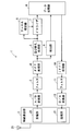
図1は本発明の実施の形態に係る通信装置1の構成を示す図である。通信装置1は、例えば、上述の非特許文献1に規定されている次世代PHSに準拠した基地局である。通信装置1は、OFDMA方式で複数の通信端末(図示せず)と双方向の無線通信を行う。通信装置1は、時間軸と周波数軸とからなる2次元で特定される無線リソースを複数の通信端末のそれぞれに個別に割り当てることによって、当該複数の通信端末と同時に通信することが可能となっている。
図1に示されるように、通信装置1は、受信部20及び送信部21を有する無線通信部2と、A/D変換器12と、フィルタ3,11と、FFT処理部4と、並び替え処理部5と、チャネル推定部6と、イコライザ7と、検出部8と、データ処理部9と、IFFT処理部10と、D/A変換器13とを備えている。受信部20及び送信部21は送受信アンテナ23を共有している。
受信部20は、送受信アンテナ23で受信されたOFDM信号に対して増幅処理やダウンコンバートを行って、当該OFDM信号をベースバンド信号に変換して出力する。A/D変換器12は、受信部20から出力されるアナログ形式のベースバンド信号をデジタル形式のベースバンド信号に変換する。
フィルタ3は、バンドパスフィルタであって、A/D変換器12から出力されるベースバンド信号をフィルタリングして出力する。FFT処理部4は、フィルタ3でフィルタリングされたベースバンド信号に対してFFT処理を行って、当該ベースバンド信号に含まれる複数のサブキャリアを分離して出力する。具体的には、FFT処理部4からは、ベースバンド信号に含まれる複数のサブキャリアのそれぞれについて、当該サブキャリアを変調する複素シンボルが出力される。
並び替え処理部5は、FFT処理部4から出力される各サブキャリアの複素シンボルを、サブキャリアの周波数の順番に並び替えて出力する。チャネル推定部6は、並び替え処理部5から出力される複素シンボルに基づいて、通信装置1(基地局)と通信端末との間の伝送路の特性を推定する。イコライザ7は、チャネル推定部6での推定結果に基づいて、並び替え処理部5から出力される複素シンボルを補正する。これにより、複素シンボルに含まれる、伝送路の特性による歪みが除去される。データ処理部9は、補正後の複素シンボルに対してデスクランブル処理やビタビ復号処理等を行って、通信端末から送信されたビットデータを再生する。
また、データ処理部9は、通信端末に向けての送信データを生成し、生成した送信データに対応する複数の複素シンボルを生成する。データ処理部9は、生成した複数の複素シンボルに対して畳み込み符号化処理やスクランブル処理等を行ってIFFT処理部10に入力する。IFFT処理部10は、入力された複数の複素シンボルに対してIFFT(Inverse FFT)処理を行って、当該複数の複素シンボルで変調された複数のサブキャリアが合成されたベースバンド信号を出力する。
フィルタ11は、IFFT処理部10から出力されるベースバンド信号をフィルタリングして出力する。D/A変換器13は、フィルタ11から出力されるデジタル形式のベースバンド信号をアナログ形式のベースバンド信号に変換する。送信部21は、D/A変換器13から出力されるベースバンド信号を、アップコンバート及び増幅処理を行った後、送受信アンテナ23に入力する。これにより、送受信アンテナ23からは、通信端末に向かって無線信号が送信される。
検出部8は、通信装置1と同期が取れていない通信端末からの信号の受信タイミングについての基準タイミングからの遅延量を検出するとともに、当該通信端末からの信号の受信レベルを検出する。データ処理部9は、検出部8で検出された遅延量を、通信端末の送信タイミングの補正量とする。また、データ処理部9は、検出部8で検出された受信レベルに基づいて、通信端末の適切な送信レベルを決定する。そして、データ処理部9は、上記補正量を通信端末に通知するための情報と、決定した送信レベルを通信端末に通知するための情報とを含む送信データを生成する。この送信データは、無線信号となって送受信アンテナ23から通信端末に送信される。
各通信端末は、通信装置1から送信タイミングの補正量が通知されると、当該補正量に基づいて送信タイミングを補正する。これにより、通信装置1では、各通信端末からの信号を適切なタイミングで受信できるようになる。その結果、通信装置1では、FFT処理部4において各通信端末からの信号を適切なタイミングでFFT処理することができるとともに、複数の通信端末からの信号の間の直交性を確保することができる。よって、通信装置1では、各通信相手装置からの信号に含まれる情報を正確に取得することができる。
また、各通信端末は、通信装置1から送信レベルが通知されると、当該送信レベルに従って信号を送信する。これにより、通信装置1においては、各通信端末からの信号の受信レベルが適切となり、受信部20において各通信端末からの信号を適切に処理することができる。さらに、通信装置1では、複数の通信端末からの信号の受信レベルが均一となり、当該信号で構成されるOFDM信号の周波数特性が平坦となる。よって、通信装置1では、各通信相手装置からの信号に含まれる情報を正確に取得することができる。
ここで、次世代PHSでは、基地局と通信端末との通信はPRU(Physical Resourse Unit)単位で行われる。例えば、基地局では、通信端末に対する無線リソースの割り当てはPRU単位で行われ、通信端末に送信データを送信する際に使用する変調方式はPRUごとに決定される。1つのPRUは、帯域幅が900kHzの1つのサブチャネルと、時間幅が625μsの1つのスロットとで表現される。1つのサブチャネルは24個のサブキャリアで構成されている。
検出部8は、通信装置1と通信端末との通信が開始したときに、当該通信端末がTCCH(Timing Correct Channel)を利用して送信する既知信号に基づいて、上記の遅延量と受信レベルを求める。図2はTCCH用のPRU100の構成例を示す図である。図2では横方向及び縦方向が時間及び周波数をそれぞれ示している。図2のS1~S19はシンボル期間の番号を示しており、図2のF1~F24はサブキャリアの周波数番号を示している。
PRU100は、時間軸と周波数軸とからなる2次元で表現される。PRU100は、図2に示されるように、複数のTCCHシンボル101と、複数のヌルシンボル102とを含んでいる。PRU100には、時間軸方向において、先頭に第1ガードタイムGT1が、末尾に第2ガードタイムGT2がそれぞれ設けられている。PRU100では、連続する3つのシンボル期間S3~S5が第1サブスロットSS1を構成し、連続する3つのシンボル期間S7~S9が第2サブスロットSS2を構成し、連続する3つのシンボル期間S11~S13が第3サブスロットSS3を構成し、連続する3つのシンボル期間S15~S17が第4サブスロットSS4を構成している。第1サブスロットSS1~第4サブスロットSS4における、周波数F2~F12,F13~F24のサブキャリアのそれぞれがTCCHシンボル101となっている。また、周波数F1のサブキャリアがガードキャリアとなっており、周波数F13のサブキャリアがDCキャリアとなっている。そして、シンボル期間S1~S19のそれぞれのガードキャリア及びDCキャリアのそれぞれがヌルシンボル102となっている。
通信端末は、自装置でのタイミングで規定された第1サブスロットSS1~第4サブスロットSS4のいずれか1つのサブスロットSSn(1≦n≦4)における複数のTCCHシンボル101を使用して、通信装置1に対して既知のTCCH信号を送信する。以後、1つのサブスロットSSnを構成する3つのシンボル期間のうち、先頭のシンボル期間Sk(k=3,7,11,15)を「先頭シンボル期間」、その次のシンボル期間S(k+1)を「中間シンボル期間」、最後のシンボル期間S(k+2)を「末尾シンボル期間」と呼ぶことがある。
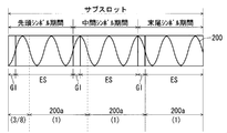
図3は、TCCH信号200の時間波形を示す図である。図3では、説明の便宜上、TCCH信号200が正弦波で示されているが、TCCH信号200は周波数の異なる複数のサブキャリアが合成されたOFDM信号であるため、実際の時間波形は正弦波とはならない。
図3に示されるように、次世代PHSの各シンボル期間は、ガードインターバルGIと有効シンボル期間ESとで構成されている。各シンボル期間では、有効シンボル期間ESにおける末尾の1/8の期間の信号が先頭のガードインターバルGIに含められる。これにより、各シンボル期間では信号の時間波形が連続する。
また、次世代PHSでは、TCCH信号200が送信される1つのサブスロットSSnでは、周波数F2~F12,F14~24のサブキャリアのそれぞれの時間波形が全期間で連続した正弦波となっている。その結果、図3に示されるように、TCCH信号200が送信される1つのサブスロットSSnでは、周波数F2~F12,F14~24のサブキャリアと、ガードキャリアと、DCサブキャリアとの合成信号、つまりTCCH信号200の時間波形が連続するようになる。
TCCH信号200では、末尾シンボル期間の有効シンボル期間ESでの周波数F2~F12,F14~24のサブキャリア(22本のサブキャリア)が、既知の複数の複素シンボルから成るTCCHシンボルパターンで変調されている。具体的には、末尾シンボル期間の有効シンボル期間ESでの22本のサブキャリアが、TCCHシンボルパターンを構成する既知の22個の複素シンボルでそれぞれで変調されている。そして、TCCH信号200では、末尾シンボル期間の最後から先頭シンボル期間の最初にかけて、末尾シンボル期間の有効シンボル期間ESでの部分信号200a(TCCHシンボルパターンで変調されている部分であって、以後「TCCHパターン信号200a」と呼ぶ)が3つと3/8だけ連続して存在している。つまり、TCCH信号200が送信される1つのサブスロットSSnでは、連続的な時間波形となるようにTCCHパターン信号200aが繰り返して送信される。
このようなTCCH信号200においては、FFT処理部4が、どの部分における有効シンボル長の信号を標本化したとしても、標本化したサブキャリア間の直交性は維持され、TCCHシンボルパターンを取得することができる。ただし、標本化する部分によっては、FFT処理部4で得られるTCCHシンボルパターンは、本来のTCCHシンボルパターンと比較して位相回転を生じることがある。
次世代PHSでは、6種類のTCCHシンボルパターンが規定されている。したがって、TCCH信号200及びTCCHパターン信号200aもそれぞれ6種類存在することになる。各通信端末は、6種類のTCCH信号200のうちの1つの種類を、1つのサブスロットSSnにおいて送信する。以後、TCCHシンボルパターンを構成する複数の複素シンボルのそれぞれを「TCCH複素シンボル」と呼ぶ。
ここで、次世代PHSでは、基地局での動作タイミングが基準タイミングとなって、基地局と通信端末とが通信を行う。そのため、通信装置1と通信端末との間で同期が取れていない場合には、通信端末からの信号が、通信装置1のFFT処理部4に適切なタイミングで入力されないことがある。その結果、通信装置1では、通信端末からの信号を適切に復調できず、当該信号に含まれる情報を正確に取得できないことがある。
そこで、本実施の形態に係る通信装置1では、検出部8が、通信端末から送信されるTCCH信号200の受信タイミングの遅延量を検出し、データ処理部9がこの遅延量を当該通信端末の送信タイミングの補正量とする。
また、通信装置1において、通信端末からの信号の受信レベルが適切な値となっていない場合にも、当該通信端末の信号に含まれる情報を正確に取得することができない。本実施の形態に通信装置1では、検出部8が、通信端末から送信されるTCCH信号200の通信装置1での受信レベルを検出し、データ処理部9が、検出された受信レベルに基づいて、当該通信端末の適切な送信レベルを決定する。
以下に検出部8の構成及び動作について詳細に説明する。
図4は検出部8の構成を示す図である。図4に示されるように、検出部8は、TCCH抜き出し部80と、6種類のTCCHシンボルパターンにそれぞれ対応して設けられた6つのTCCH処理部81とを備えている。TCCH抜き出し部80は、FFT処理部4の出力信号から、TCCH用のPRU100におけるシンボル期間S1~S19での各サブキャリアの複素シンボルを抜き出す。以後、TCCH抜き出し部80で抜き出された複素シンボルを「復調複素シンボル」と呼ぶ。
各TCCH処理部81は、当該TCCH処理部81に対応するTCCHシンボルパターンと復調複素シンボルとの相関演算を行う相関演算部812と、相関演算部812での演算結果に基づいて、通信端末からの信号の受信タイミングの遅延量と当該信号の受信レベルを求める受信状態取得部815とを備えている。相関演算部812は、相関値算出部810とIFFT処理部811を有し、受信状態取得部815は、演算結果処理部813と状態取得部814と備えている。
相関値算出部810は、TCCH抜き出し部80で抜き出された複数の復調複素シンボルから、1つのサブスロットSSnの末尾シンボル期間における、周波数F1~F12,F14~F24のサブキャリアについての復調複素シンボルを取得する。そして、相関値算出部810は、取得した複数の復調複素シンボルから成る復調複素シンボルパターンと、当該相関値算出部810が属するTCCH処理部81に対応する1つの種類のTCCHシンボルパターンとの相関値を求める。具体的には、相関値算出部810は、末尾シンボル期間における複数の復調複素シンボルのそれぞれについて、当該復調複素シンボルと、それと同じ周波数のサブキャリアを変調するTCCH複素シンボルとの相関値を求める。
図5は相関値を求める方法を説明するための図である。周波数番号Fm(m=1~12,14~24)のサブキャリアについての復調複素シンボルを(am+jbm)、当該サブキャリアについてのTCCH複素シンボルを(cm+jdm)とすると、相関値算出部810は、(am+jbm)と(cm-jbm)とを掛け合わせて得られる複素数(am+jbm)・(cm-jbm)を相関値とする。これにより、末尾シンボル期間について、復調複素シンボルとTCCH複素シンボルとの相関値が22個得られる。
さらに、相関値算出部810は、末尾シンボル期間S(k+2)の後に連続するシンボル期間S(k+3)、例えば、第1サブスロットSS1の末尾シンボル期間S5であれば、シンボル期間S6における複数の復調複素シンボルのそれぞれについて、当該復調複素シンボルと、それと同じ周波数のサブキャリアを変調するTCCH複素シンボルとの相関値を同様にして求める。これにより、末尾シンボル期間S(k+2)の後に連続するシンボル期間S(k+3)について、復調複素シンボルとTCCH複素シンボルとの相関値が22個得られる。
各相関値算出部810は、以上のような相関値の算出を、第1サブスロットSS1~第4サブスロットSS4のそれぞれについて行う。したがって、各相関値算出部810では、第1サブスロットSS1の末尾シンボル期間S5とそれに続くシンボル期間S6での相関値が求められる。また、各相関値算出部810では、第2サブスロットSS2の末尾シンボル期間S9とそれに続くシンボル期間S10での相関値と、第3サブスロットSS3の末尾シンボル期間S13とそれに続くシンボル期間S14での相関値とが求められる。そして、各相関値算出部810では、第4サブスロットSS4の末尾シンボル期間S17とそれに続くシンボル期間S18での相関値とが求められる。
通信端末からは、第1サブスロットSS1~第4サブスロットSS4のいずれかのサブスロットSSnにおいてTCCHシンボルパターンが送信されることから、第1サブスロットSS1~第4サブスロットSS4のそれぞれについて上記のような相関値を求めることにより、通信装置1では、通信端末から受信したTCCHシンボルパターンと、予め記憶する理想的なTCCHシンボルパターンとの相関値を求めることができる。
IFFT処理部811は、相関値算出部810で求められた相関値に対してIFF処理を行う。具体的には、IFFT処理部811は、第1サブスロットSS1~第4サブスロットSS4のそれぞれについて、末尾シンボル期間での22個の相関値に対してIFFT処理を行うとともに、当該末尾シンボル期間の後に続くシンボル期間での22個の相関値に対してIFFT処理を行う。
ここで、本実施の形態では、IFFTのサンプル数(ポイント数)は例えば128であるため、IFFT処理部811への入力数は128必要である。そのため、IFFT処理部811には、22個の相関値と、106個の零の値を入力する。これにより、IFFT処理部811からは、時系列順に並ぶ128個のサンプル値が出力される。本実施の形態では、IFFT処理部811から出力される、時系列順に並ぶ128個のサンプル値に対してサンプル番号0~127をそれぞれ付与する。
IFFT処理部811から出力されるサンプル値は、TCCHシンボルパターンを位相回転して得られる遅延TCCHシンボルパターンと、復調複素シンボルパターンとの相関値を示している。具体的には、サンプル番号l(0≦l≦127)のサンプル値は、有効シンボル長をTとすると、TCCHシンボルパターンを(T×l/128)に相当する量だけ位相回転して得られる遅延TCCHシンボルパターンと、復調複素シンボルパターンとの相関値を示している。つまり、サンプル番号lのサンプル値は、TCCHシンボルパターンを構成する複数のTCCH複素シンボルをそれぞれ(T×l/128)に相当する量だけ位相回転して得られる複数の遅延TCCH複素シンボルと、複数の復調複素シンボルとのそれぞれの相関値の総和となる。サンプル番号lのサンプル値SMPlは、周波数番号Fmのサブキャリアについての遅延TCCH複素シンボルを(ccm+jddm)とすると、以下の式(1)で表現される。
SMPl=(a1+jb1)・(cc1-jdd1)+(a2+jb2)・(cc2-jdd2)+・・・+(a12+jb12)・(cc12-jdd12)+(a14+jb14)・(cc14-jdd14)+(a15+jb15)・(cc15-jdd15)+・・・+(a24+jb24)・(cc24-jdd24) ・・・(1)
なお、サンプル番号0のサンプル値SMP0は、複数の本来のTCCH複素シンボルと複数の復調複素シンボルとのそれぞれの相関値の総和となる。
IFFT処理部811では、第1サブスロットSS1~第4サブスロットSS4のそれぞれについて、末尾シンボル期間S(k+2)での128個のサンプル値と、当該末尾シンボル期間S(k+2)の後に続くシンボル期間S(k+3)での128個のサンプル値が得られる。つまり、各IFFT処理部811では、それに対応するTCCHシンボルパターンに応じて、128個のサンプル値が8組得られる。
演算結果処理部813は、IFFT処理部811で得られたサンプル値の各組について、128個のサンプル値のそれぞれの大きさを求める。具体的には、演算結果処理部813は、サンプル値SMPlを(el+jfl)とすると、当該サンプル値SMPlの大きさとして(el2+fl2)を求める。図6は、一組の128個のサンプル値の大きさの一例を示す図である。図6では横軸がサンプル番号を示し、縦軸がサンプル値の大きさを示している。以後、1つのシンボル期間における128個のサンプル値を図6のように示したグラフを「相関値グラフ」と呼ぶ。
演算結果処理部813は、サンプル値の各組について全サンプル値の大きさを求めると、第1サブスロットSS1~第4サブスロットSS4のそれぞれについて、末尾シンボル期間S(k+2)での128個のサンプル値の大きさのピーク値(最大値)を求めるとともに、当該ピーク値の大きさを有するサンプル値のサンプル番号(以後、「ピーク位置」と呼ぶ)を特定する。図6の例では、サンプル番号50のサンプル値の大きさがピークを示しているため、ピーク位置は“50”となる。
また、演算結果処理部813は、第1サブスロットSS1~第4サブスロットSS4のそれぞれについて、末尾シンボル期間S(k+2)の後に続くシンボル期間S(k+3)での128個のサンプル値の大きさのピーク値を求める。
さらに、演算結果処理部813は、第1サブスロットSS1~第4サブスロットSS4のそれぞれについて、末尾シンボル期間S(k+2)での128個のサンプル値の平均値(以後、単に「平均値」と呼ぶ)を求める。
状態取得部814は、演算結果処理部813で求められたピーク値、ピーク位置及び平均値に基づいて、通信端末からの信号の受信タイミングの遅延量と当該信号の受信レベルを求める。以下に、状態取得部814の動作について図7,8を参照して詳細に説明する。
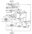
図7は、状態取得部814における、1つのサブスロットSSnでのピーク値、ピーク位置及び平均値を使用した処理を示すフローチャートである。
図8はTCCH信号についての様々な受信タイミングを示す図である。図8では、通信装置1でのタイミングで規定されたシンボル期間Sk~S(k+4)が一番上に示されている。また図8での受信タイミング(A)は、通信装置1において通信端末からのTCCH信号の受信タイミングに遅延がほぼ無い状態を示している。また図8での受信タイミング(B)~(F)は、通信装置1での通信端末からのTCCH信号の受信タイミングが遅延している状態を示している。TCCH信号の受信タイミングの遅延量は、受信タイミング(B)~(F)の順で大きくなっている。受信タイミング(E),(F)では1シンボル期間以上TCCH信号の受信タイミングが遅れている。なお、図8では、各TCCH信号の下に、当該TCCH信号が図8に示される受信タイミングで受信された際のシンボル期間Sk~S(k+3)でのそれぞれの相関値グラフを示している。
図7に示されるように、ステップST1において、状態取得部814は、処理対象の1つのサブスロットSSnにおける末尾シンボル期間S(k+2)でのピーク値(図7ではピーク値(S(k+2))と示す)が、当該末尾シンボル期間S(k+2)での平均値(図7では平均値(S(k+2))と示す)に対して十分大きいかどうかを判定する。具体的には、状態取得部814は、末尾シンボル期間S(k+2)でのピーク値が、末尾シンボル期間S(k+2)での平均値のα(α>1)倍よりも大きいかを判定する。末尾シンボル期間S(k+2)において、ピーク値が平均値よりも十分に大きくない場合には、末尾シンボル期間S(k+2)での復調複素シンボルパターンと相関のある遅延TCCH複素シンボルパターンが存在しないと判定できる。したがって、この場合には、状態取得部814は、処理対象の1つのサブスロットSSnにおいて通信端末からのTCCH信号が受信されていないか、受信されたTCCH信号に含まれるTCCHシンボルパターンが、当該状態取得部814が属するTCCH処理部81に対応するシンボルパターンではないかのどちらかであると判断し、当該1つのサブスロットSSnについての処理を終了する。一方で、末尾シンボル期間S(k+2)において、ピーク値が平均値よりも十分に大きい場合には、末尾シンボル期間S(k+2)での復調複素シンボルパターンと相関のある遅延TCCH複素シンボルパターンが存在することになる。したがって、状態取得部814は、処理対象の1つのサブスロットSSnにおいて通信端末からのTCCH信号が受信されたと判定して、次のステップST2を実行する。
ステップST2では、状態取得部814は、末尾シンボル期間S(k+2)でのピーク値を、通信端末からのTCCH信号の受信レベルとする。状態取得部814は、ステップST2を実行すると、ステップST3において、末尾シンボル期間S(k+2)でのピーク位置(図7ではピーク位置(S(k+2))と示す)が、16よりも大きくかつ111よりも小さいかを判定する。状態取得部814は、末尾シンボル期間S(k+2)でのピーク位置が、16以下あるいは111以上と判定すると、TCCH信号の受信状態が図8の(A)あるいは(D)であると判定し、ステップST4を実行する。一方で、状態取得部814は、末尾シンボル期間S(k+2)でのピーク位置が、16よりも大きくかつ111よりも小さいと判定すると、TCCH信号の受信タイミングが、図8の(B)、(C)、(E)、(F)のいずれかであると判定し、ステップST5を実行する。
ステップST4では、状態取得部814は、末尾シンボル期間S(k+2)の後に続くシンボル期間S(k+3)でのピーク値(図7ではピーク値(S(k+3))と示す)が小さいかを判定する。具体的には、状態取得部814は、シンボル期間S(k+3)でのピーク値のβ(β>1)倍が末尾シンボル期間S(k+2)でのピーク値よりも小さいかを判定する。状態取得部814は、シンボル期間S(k+3)でのピーク値が小さいと判定すると、TCCH信号の受信タイミングが図8の(A)、つまり、TCCH信号がシンボル期間S(k+3)に入り込んでいないと判定し、ステップST6を実行する。
一方で、状態取得部814は、シンボル期間S(k+3)でのピーク値が小さくないと判定すると、TCCH信号の受信タイミングが図8の(D)、つまり、TCCH信号がシンボル期間S(k+3)に入り込んでいると判定し、ステップST7を実行する。
ステップST6では、状態取得部814は、末尾シンボル期間S(k+2)でのピーク位置が16よりも大きいかを判定する。ここで、図8の(A)のように、TCCH信号の受信タイミングにほぼ遅れがない場合には、末尾シンボル期間S(k+2)でのピーク位置は、最小値の零に近い理想的な値となるか、最大値の127に近い値となる。ステップST6では、末尾シンボル期間S(k+2)でのピーク位置が、どちらの値にあるかを判断している。状態取得部814は、末尾シンボル期間S(k+2)でのピーク位置が16よりも大きいと判定すると、ステップST8において、TCCH信号の受信タイミングの遅延量を零とする。
一方で、状態取得部814は、末尾シンボル期間S(k+2)でのピーク位置が16以下であると判定すると、ステップST9において、末尾シンボル期間S(k+2)でのピーク位置を、TCCH信号の受信タイミングの遅延量とする。上述のように、IFFT処理部811から出力されるサンプル番号lのサンプル値は、有効シンボル長をTとすると、TCCHシンボルパターンを(T×l/128)に相当する量だけ位相回転して得られる遅延TCCHシンボルパターンと、復調複素シンボルパターンとの相関値を示している。したがって、末尾シンボル期間S(k+2)でのピーク位置をLとすると、末尾シンボル期間S(k+2)での復調複素シンボルパターンは、TCCHシンボルパターンを(T×L/128)に相当する量だけ位相回転して得られる遅延TCCHシンボルパターンと相関がとれていることになる。したがって、時間領域で考えると、TCCH信号の受信タイミングは、(T×L/128)だけ遅延していることになる。よって、ピーク位置は、TCCH信号の受信タイミングの遅延量を示していることになる。
状態取得部814は、上述のステップST4において、TCCH信号の受信タイミングが図8の(D)の状態であると判定すると、ステップST7において、末尾シンボル期間S(k+2)でのピーク位置が111よりも小さいかを判定する。図8の(D)のように、TCCH信号の遅延量がほぼ有効シンボル長Tだけ遅延した場合には、末尾シンボル期間S(k+2)でのピーク位置は、最大値“127”に近い理想的な値となるか、最小値の零に近い値となる。ステップST7では、末尾シンボル期間S(k+2)でのピーク位置が、どちらの値にあるかを判断している。状態取得部814は、末尾シンボル期間S(k+2)でのピーク位置が111よりも小さいと判定すると、ステップST10において、TCCH信号の受信タイミングの遅延量を“127”とする。一方で、状態取得部814は、末尾シンボル期間S(k+2)でのピーク位置が111以上であると判定すると、上述のステップST9を実行して、末尾シンボル期間S(k+2)でのピーク位置をTCCH信号の受信タイミングの遅延量とする。
状態取得部814は、上述のステップST3において、TCCH信号の受信タイミングが、図8の(B)、(C)、(E)、(F)のいずれかであると判定すると、ステップST5において、末尾シンボル期間S(k+2)の後に続くシンボル期間S(k+3)でのピーク値が大きいかを判定する。具体的には、状態取得部814は、ステップST4と同様に、シンボル期間S(k+3)でのピーク値のβ倍が末尾シンボル期間S(k+2)でのピーク値よりも小さいかを判定する。状態取得部814は、シンボル期間S(k+3)でのピーク値が大きくない、つまりシンボル期間S(k+3)でのピーク値のβ倍が末尾シンボル期間S(k+2)でのピーク値よりも小さいと判定すると、TCCH信号の受信タイミングが図8の(B),(C)のいずれか、つまりTCCH信号がシンボル期間S(k+3)にあまり入り込んでおらず、TCCH信号の遅延が1シンボル期間以内であると判定し、上述のステップST9を実行して、末尾シンボル期間S(k+2)でのピーク位置をTCCH信号の受信タイミングの遅延量とする。
一方で、状態取得部814は、シンボル期間S(k+3)でのピーク値が大きい、つまり、シンボル期間S(k+3)でのピーク値のβ倍が末尾シンボル期間S(k+2)でのピーク値以上であると判定すると、TCCH信号の受信タイミングが図8の(E),(F)のいずれか、つまり、TCCH信号が1シンボル期間以上遅延していると判定し、ステップST11を実行する。
ステップST11では、状態取得部814は、末尾シンボル期間S(k+2)でのピーク位置に対して、有効シンボル長に相当する“128”を足し合わせて得られる値を、TCCH信号の受信タイミングの遅延量とする。
ここで、TCCH信号が1シンボル期間だけ遅延した際には、時間領域で考えると、TCCH信号における末尾シンボル期間S(k+2)での波形(図3での中間シンボル期間の有効シンボル期間ESでの波形)は、TCCHパターン信号200aよりも、ガードインターバルGIと同じ時間だけ進んでいる。したがって、TCCH信号が1シンボル期間だけ遅延した際には、末尾シンボル期間S(k+2)でのピーク位置は、TCCH信号の受信タイミングに遅延が無いときの末尾シンボル期間S(k+2)でのピーク位置よりもガードインターバルGIに相当する分だけ大きくなっている。したがって、状態取得部814では、TCCH信号が1シンボル期間以上遅延していると判定した際には、末尾シンボル期間S(k+2)でのピーク位置に対して、1シンボル期間に相当する値ではなく、有効シンボル長に相当する“128”を足し合わせる。
状態取得部814は、ステップST1において、末尾シンボル期間S(k+2)でのピーク値が平均値よりも十分に大きくないと判定した際には、処理対象の1つのサブスロットSSnを変更して同様の処理を行う。
データ処理部9は、状態取得部814で求められた遅延量を、通信端末の送信タイミングの補正量とする。また、データ処理部9は、状態取得部814で求められた受信レベルに基づいて、通信端末の送信レベルを決定する。つまり、データ処理部9は、通信端末の送信レベルを決定する決定部として機能する。そして、データ処理部9は、上記の補正量を通信端末に通知するための情報と、決定した送信レベルを通信端末に通知するための情報とを含む送信データを生成する。この送信データは、無線信号となって送信部21の送受信アンテナ23から通信端末に送信される。
以上のように、本実施の形態に係る通信装置1では、相関演算部812が、一の単位期間である末尾シンボル期間S(k+2)及びそれに続く単位期間であるシンボル期間S(k+3)のそれぞれにおいて、復調複素シンボルパターン(受信部20で受信された信号の周波数成分)と、TCCHシンボルパターン(既知のTCCHパターン信号200aの周波数成分)との相関演算を行っている。そして、受信状態取得部815が、相関演算部812での演算結果に基づいて、通信端末からの信号の受信タイミングの遅延量を求めている。
図8に示されるように、TCCH信号200の受信タイミングの遅延量が大きくなると、TCCH信号200においてシンボル期間S(k+3)で受信される部分が増加する。したがって、シンボル期間S(k+3)についての、復調複素シンボルパターンと、TCCHシンボルパターンとの相関演算結果から、上述のステップST5のように、TCCH信号200が1シンボル期間以上遅延しているか否かを検出することができる。上述のステップST5においては、シンボル期間S(k+3)についての、復調複素シンボルパターンと、TCCHシンボルパターンとの相関演算結果であるピーク値が大きい場合には、TCCH信号200が1シンボル期間以上遅延していると判定している。
また、通信端末から送信されるTCCH信号200は、1つのサブスロットSSnの間、TCCHパターン信号200aが繰り返された連続波形であることから、通信装置1では、TCCH信号200の受信タイミングが1シンボル期間以上遅延したとしても、末尾シンボル期間S(k+2)においてTCCH信号200が連続して受信されることになる。よって、末尾シンボル期間S(k+2)での復調複素シンボルパターンと、TCCHシンボルパターンとの相関演算を適切に行うことができる。したがって、当該相関演算の演算結果と、TCCH信号200が1シンボル期間以上遅延しているか否かの判定結果とに基づいて、通信端末からの信号の受信タイミングについての1シンボル期間以上の遅延を求めることができる(ステップST9,ST11)。よって、通信端末からの信号の受信タイミングについての遅延量の検出精度が向上する。
<処理対象となるシンボル期間の組み合わせの変形例>
上述の例では、通信端末からの信号の受信タイミングが1シンボル期間以上遅れているか否かの判定を行う際に、1つのサブスロットSSnに続くシンボル期間S(k+3)での復調複素シンボルパターンとTCCHシンボルパターンとの相関演算結果を使用したが、その代わりに、1つのサブスロットSSnの先頭シンボル期間Skでの復調複素シンボルパターンとTCCHシンボルパターンとの相関演算結果を使用しても良い。図8に示されるように、TCCH信号200の受信タイミングの遅延量が大きくなると、TCCH信号200において先頭シンボル期間Skで受信される部分が減少する。したがって、先頭シンボル期間Skについての、復調複素シンボルパターンと、TCCHシンボルパターンとの相関演算結果から、TCCH信号200が1シンボル期間以上遅延しているか否かを検出することができる。例えば、相関演算部812において、先頭シンボル期間Skについてのピーク値を求めて、当該ピーク値が小さい場合には、TCCH信号200が1シンボル期間以上遅延していると判定する。
上述の例では、通信端末からの信号の受信タイミングが1シンボル期間以上遅れているか否かの判定を行う際に、1つのサブスロットSSnに続くシンボル期間S(k+3)での復調複素シンボルパターンとTCCHシンボルパターンとの相関演算結果を使用したが、その代わりに、1つのサブスロットSSnの先頭シンボル期間Skでの復調複素シンボルパターンとTCCHシンボルパターンとの相関演算結果を使用しても良い。図8に示されるように、TCCH信号200の受信タイミングの遅延量が大きくなると、TCCH信号200において先頭シンボル期間Skで受信される部分が減少する。したがって、先頭シンボル期間Skについての、復調複素シンボルパターンと、TCCHシンボルパターンとの相関演算結果から、TCCH信号200が1シンボル期間以上遅延しているか否かを検出することができる。例えば、相関演算部812において、先頭シンボル期間Skについてのピーク値を求めて、当該ピーク値が小さい場合には、TCCH信号200が1シンボル期間以上遅延していると判定する。
また、末尾シンボル期間S(k+2)での復調複素シンボルパターンとTCCHシンボルパターンとの相関演算結果を使用する代りに、中間シンボル期間S(k+1)での復調複素シンボルパターンとTCCHシンボルパターンとの相関演算結果を使用しても良い。通信装置1では、TCCH信号200の受信タイミングが1シンボル期間遅延した場合には、中間シンボル期間S(k+1)においてTCCH信号200を連続して受信することができる。また通信装置1では、TCCH信号200の受信タイミングが1シンボル期間よりも多少多く遅延した場合であっても、中間シンボル期間S(k+1)の大部分においてTCCH信号を連続して受信することができる。したがって、中間シンボル期間S(k+1)での復調複素シンボルパターンと、TCCHシンボルパターンとの相関演算を適切に行うことができる。中間シンボル期間S(k+1)での復調複素シンボルパターンとTCCHシンボルパターンとの相関演算結果を使用する際には、相関演算部812において中間シンボル期間S(k+1)でのピーク位置を求めて、TCCH信号200が1シンボル期間以上遅延していると判定した際には、当該ピーク位置に“128”を足し合わせることによって、遅延量を求めることができる。ただし、TCCH信号200の受信タイミングに遅延が無い場合であっても、図3に示されるように、TCCH信号200のうち、中間シンボル期間S(k+1)の有効シンボル期間ESでの信号波形は、TCCHパターン信号200aよりも、ガードインターバルGIと同じ時間だけ進んでいる。したがって、このようにして求めた遅延量は、ガードインターバルGIの分だけ、実際の遅延量よりも大きくなっている。よって、中間シンボル期間S(k+1)でのピーク位置を使用する場合には、求めた遅延量からガードインターバルGIの分だけ減算する補正が必要である。
また、1つのサブスロットSSnを構成する、先頭シンボル期間Sk、中間シンボル期間S(k+1)及び末尾シンボル期間S(k+2)のそれぞれについて、復調複素シンボルパターンと、TCCHシンボルパターンとの相関演算を行い、これらの相関演算に基づいて通信端末からの信号の受信タイミングの遅延量を求めることによって、当該受信タイミングについての2シンボル期間以上の遅延を検出することができる。つまり、相関演算を行う対象の少なくとも2つのシンボル期間は、先頭シンボル期間Skとそれに続く複数のシンボル期間とから成ることが望ましい。TCCH信号200の受信タイミングの遅延量が大きくなると、まず、TCCH信号200において先頭シンボル期間Skで受信される部分が減少する。そして、当該遅延量がさらに大きくなると、今度は、TCCH信号200において中間シンボル期間S(k+1)で受信される部分が減少する。したがって、先頭シンボル期間Skについての復調複素シンボルパターンとTCCHシンボルパターンとの相関演算結果と、中間シンボル期間S(k+1)での復調複素シンボルパターンとTCCHシンボルパターンとの相関演算結果とを使用することによって、TCCH信号200の受信タイミングの遅延量が、1シンボル期間未満であるか、1シンボル期間以上2シンボル期間未満であるか、2シンボル期間以上であるかを識別することができる。TCCH信号200の受信タイミングの遅延量が、1シンボル期間以上2シンボル期間未満である場合には、末尾シンボル期間S(k+2)でのピーク値に“128”を足し合わせて得られる値を遅延量とする。また、TCCH信号200の受信タイミングの遅延量が2シンボル期間以上である場合には、末尾シンボル期間S(k+2)でのピーク値に“256”を足し合わせて得られる値を遅延量とする。これにより、通信端末からの信号の受信タイミングについて、2シンボル期間以上の遅延を検出することができる。
<検出部の変形例>
上記の例では、相関値算出部810で算出された、TCCHシンボルパターンと復調複素シンボルパターンとの相関値に対してIFFT処理部811でIFFT処理を行うことによって、遅延TCCHシンボルパターンと復調複素シンボルパターンとの相関値を求めていたが、IFFT処理を行わずに当該相関値を求めても良い。図9はこの場合の検出部8aの構成を示す図である。図9の検出部8aは、図4の検出部8において、相関演算部812の代わりに相関演算部812aを設けたものである。
上記の例では、相関値算出部810で算出された、TCCHシンボルパターンと復調複素シンボルパターンとの相関値に対してIFFT処理部811でIFFT処理を行うことによって、遅延TCCHシンボルパターンと復調複素シンボルパターンとの相関値を求めていたが、IFFT処理を行わずに当該相関値を求めても良い。図9はこの場合の検出部8aの構成を示す図である。図9の検出部8aは、図4の検出部8において、相関演算部812の代わりに相関演算部812aを設けたものである。
各相関演算部812aは、1つのサブスロットSSnの末尾シンボル期間S(k+2)について、復調複素シンボルパターンと、当該相関演算部812aが属するTCCH処理部81に対応したTCCHシンボルパターンを(T×r/128)に相当する量だけ位相回転して得られる遅延TCCHシンボルパターンとの相関値(以後、「遅延相関値」と呼ぶ)を、rが取り得る各値について、上述の式(1)のように求める。ここで、rは0以上127以下の整数である。これにより、上述の図6の相関値グラフと同様のグラフを得ることができる。
同様にして、相関演算部812aは、当該1つのサブスロットSSnに続くシンボル期間S(k+3)について、復調複素シンボルパターンと、当該相関演算部812aが属するTCCH処理部81に対応したTCCHシンボルパターンを(T×r/128)に相当する量だけ位相回転して得られる遅延TCCHシンボルパターンとの相関値(遅延相関値)を、rが取り得る各値について、上述の式(1)のように求める。
相関演算部812aは、これらの遅延相関値を、第1サブスロットSS1~第4サブスロットSS4のそれぞれについて求める。これにより、各相関演算部812aでは、それに対応するTCCHシンボルパターンに応じて、128個の遅延相関値が8組得られる。
本変形例に係る受信状態取得部815では、上述のサンプル値が遅延相関値に置き換えられて同様の処理が行われる。これにより、上記例と同様に、検出部8aでは、通信端末からの信号の受信タイミングについて、1シンボル期間以上の遅延量を検出することができる。
以上の実施の形態及びその変形例では、本願発明を次世代PHSに適用する場合について説明したが、本願発明は次世代PHS以外の他の通信システム、例えばLTE(Long Term Evolution)やWiMAX(Worldwide Interoperability for Microwave Access)にも当然に適用することができる。
この発明は詳細に説明されたが、上記した説明は、すべての局面において、例示であって、この発明がそれに限定されるものではない。例示されていない無数の変形例が、この発明の範囲から外れることなく想定され得るものと解される。
1 通信装置
9 データ処理部
20 受信部
21 送信部
812,812a 相関演算部
815 受信状態取得部
9 データ処理部
20 受信部
21 送信部
812,812a 相関演算部
815 受信状態取得部
Claims (6)
- 通信相手装置と通信を行う通信装置であって、
前記通信相手装置でのタイミングで規定された、連続する複数の相手側単位期間の間、前記通信相手装置から、連続的に繰り返して送信される既知信号を受信する受信部と、
前記通信装置でのタイミングで規定された、前記複数の相手側単位期間に相当する複数の自装置側単位期間及び当該複数の自装置側単位期間に続く1つの後続自装置側単位期間において、先頭の単位期間及び末尾の単位期間のどちらか一方と、当該先頭の単位期間を除いた前記複数の自装置側単位期間のうちの一つとを含む少なくとも2つの単位期間のそれぞれにおいて、前記受信部が受信する信号と前記既知信号との相関演算を行う相関演算部と、
前記相関演算部での演算結果に基づいて、前記通信相手装置からの信号の受信タイミングの遅延量を求める遅延量取得部と
を備える、通信装置。 - 請求項1に記載の通信装置であって、
前記少なくとも2つの単位期間は、前記複数の相手側単位期間に相当する複数の自装置側単位期間及び当該複数の自装置側単位期間に続く1つの後続自装置側単位期間において、先頭の単位期間と、当該先頭の単位期間に連続して続く複数の単位期間とから成る、通信装置。 - 請求項2に記載の通信装置であって、
前記遅延量取得部で求められた前記遅延量を通知する信号を前記通信相手装置に送信する送信部をさらに備える、通信装置。 - 請求項3に記載の通信装置であって、
前記相関演算部での演算結果に基づいて、前記通信相手装置からの信号の受信レベルを求める受信レベル取得部をさらに備える、通信装置。 - 請求項4に記載の通信装置であって、
前記受信レベル取得部で求められた前記受信レベルに基づいて、前記通信相手装置での送信レベルを決定する決定部と、
前記決定部で決定された前記送信レベルを通知する信号を前記通信相手装置に送信する送信部と
をさらに備える、通信装置。 - 通信装置において、通信相手装置からの信号の受信タイミングの遅延量を検出する遅延量検出方法であって、
前記通信相手装置でのタイミングで規定された、連続する複数の相手側単位期間の間、前記通信相手装置から、連続的に繰り返して送信される既知信号を受信する受信工程と、
前記通信装置でのタイミングで規定された、前記複数の相手側単位期間に相当する複数の自装置側単位期間及び当該複数の自装置側単位期間に続く1つの後続自装置側単位期間において、先頭の単位期間及び末尾の単位期間のどちらか一方と、当該先頭の単位期間を除いた前記複数の自装置側単位期間のうちの一つとを含む少なくとも2つの単位期間のそれぞれにおいて、前記受信部が受信する信号と、前記既知信号との相関演算を行う演算工程と、
前記演算工程での演算結果に基づいて、前記通信相手装置からの信号の受信タイミングの遅延量を求める遅延量取得工程と
を備える、遅延量検出方法。
Priority Applications (1)
| Application Number | Priority Date | Filing Date | Title |
|---|---|---|---|
| US13/318,239 US8780942B2 (en) | 2009-06-26 | 2010-06-09 | Communication device and a delay amount detection method |
Applications Claiming Priority (2)
| Application Number | Priority Date | Filing Date | Title |
|---|---|---|---|
| JP2009-153011 | 2009-06-26 | ||
| JP2009153011A JP5284891B2 (ja) | 2009-06-26 | 2009-06-26 | 通信装置及び遅延量検出方法 |
Publications (1)
| Publication Number | Publication Date |
|---|---|
| WO2010150652A1 true WO2010150652A1 (ja) | 2010-12-29 |
Family
ID=43386424
Family Applications (1)
| Application Number | Title | Priority Date | Filing Date |
|---|---|---|---|
| PCT/JP2010/059735 Ceased WO2010150652A1 (ja) | 2009-06-26 | 2010-06-09 | 通信装置及び遅延量検出方法 |
Country Status (3)
| Country | Link |
|---|---|
| US (1) | US8780942B2 (ja) |
| JP (1) | JP5284891B2 (ja) |
| WO (1) | WO2010150652A1 (ja) |
Families Citing this family (2)
| Publication number | Priority date | Publication date | Assignee | Title |
|---|---|---|---|---|
| JP2012222652A (ja) * | 2011-04-11 | 2012-11-12 | Kyocera Corp | 通信装置、通信システム及び通信方法 |
| CN114553655A (zh) * | 2020-11-25 | 2022-05-27 | 华为技术有限公司 | 一种数据传输方法和装置以及系统 |
Citations (1)
| Publication number | Priority date | Publication date | Assignee | Title |
|---|---|---|---|---|
| JP2009010662A (ja) * | 2007-06-27 | 2009-01-15 | Kyocera Corp | 無線通信システム、送信装置、受信装置、シンボル同期方法 |
Family Cites Families (2)
| Publication number | Priority date | Publication date | Assignee | Title |
|---|---|---|---|---|
| JP4763785B2 (ja) * | 2006-06-26 | 2011-08-31 | 京セラ株式会社 | Ofdm通信装置及びガードインターバル長決定方法 |
| JP4655241B2 (ja) * | 2008-09-30 | 2011-03-23 | ソニー株式会社 | 受信装置、受信方法、およびプログラム |
-
2009
- 2009-06-26 JP JP2009153011A patent/JP5284891B2/ja not_active Expired - Fee Related
-
2010
- 2010-06-09 WO PCT/JP2010/059735 patent/WO2010150652A1/ja not_active Ceased
- 2010-06-09 US US13/318,239 patent/US8780942B2/en not_active Expired - Fee Related
Patent Citations (1)
| Publication number | Priority date | Publication date | Assignee | Title |
|---|---|---|---|---|
| JP2009010662A (ja) * | 2007-06-27 | 2009-01-15 | Kyocera Corp | 無線通信システム、送信装置、受信装置、シンボル同期方法 |
Also Published As
| Publication number | Publication date |
|---|---|
| JP2011010146A (ja) | 2011-01-13 |
| US8780942B2 (en) | 2014-07-15 |
| US20120044832A1 (en) | 2012-02-23 |
| JP5284891B2 (ja) | 2013-09-11 |
Similar Documents
| Publication | Publication Date | Title |
|---|---|---|
| US8306012B2 (en) | Channel estimation for synchronized cells in a cellular communication system | |
| EP1908239B1 (en) | Co-channel interference mitigation for OFDM | |
| US10944496B2 (en) | Time-domain and frequency-domain approach to frequency offset correction method for LTE SC-FDMA uplink | |
| CN102812679B (zh) | 用于无线通讯系统中准确时间同步的方法及装置 | |
| US8654914B2 (en) | System and method for adaptive time synchronization | |
| KR20070056480A (ko) | 직교주파수다중 방식의 무선통신 시스템에서 반송파 주파수동기 장치 및 방법 | |
| KR100542115B1 (ko) | Ofdma기반 셀룰러 시스템 기지국의 위상 왜곡 보상장치 및 방법 | |
| US8045538B2 (en) | Wireless communication method, receiving method, and wireless communication device | |
| US7724804B2 (en) | Receiving apparatus and channel estimating apparatus | |
| CN107317779B (zh) | 一种频偏估计方法和装置 | |
| EP2499797B1 (en) | Channel estimation in a multi-user mimo-ofdm system in the presence of user terminal symbol-specific phase offsets | |
| JP2005045628A (ja) | Ofdm通信方式の受信装置 | |
| US20140140449A1 (en) | Communication method and reception apparatus | |
| CN110115010A (zh) | 用于在多载波脉冲整形传输系统中传送非脉冲整形信号的接收机、发送机、无线通信网络和方法 | |
| JP5284891B2 (ja) | 通信装置及び遅延量検出方法 | |
| EP2770685B1 (en) | Ofdm packets time synchronisation | |
| JP5045127B2 (ja) | 無線通信システム | |
| JP7584491B2 (ja) | 協調ビームフォーミングのためのガードインターバル適応 | |
| JP4812567B2 (ja) | パイロット信号の割り当て方法およびそれを利用した無線装置 | |
| US9154358B2 (en) | Wireless communication device and method of determining reference signal | |
| EP1908243B1 (en) | Co-channel interference mitigation for OFDM | |
| JP4714635B2 (ja) | マルチキャリア受信装置及びマルチキャリア受信装置の制御方法 | |
| JP2009088993A (ja) | 無線通信装置及び受信品質推定方法 | |
| JP2009089041A (ja) | 無線通信装置及び受信品質推定方法 |
Legal Events
| Date | Code | Title | Description |
|---|---|---|---|
| 121 | Ep: the epo has been informed by wipo that ep was designated in this application |
Ref document number: 10791970 Country of ref document: EP Kind code of ref document: A1 |
|
| WWE | Wipo information: entry into national phase |
Ref document number: 13318239 Country of ref document: US |
|
| NENP | Non-entry into the national phase |
Ref country code: DE |
|
| 122 | Ep: pct application non-entry in european phase |
Ref document number: 10791970 Country of ref document: EP Kind code of ref document: A1 |