WO2010146823A1 - 液面検出器およびこれを備えたリザーバタンク - Google Patents
液面検出器およびこれを備えたリザーバタンク Download PDFInfo
- Publication number
- WO2010146823A1 WO2010146823A1 PCT/JP2010/003927 JP2010003927W WO2010146823A1 WO 2010146823 A1 WO2010146823 A1 WO 2010146823A1 JP 2010003927 W JP2010003927 W JP 2010003927W WO 2010146823 A1 WO2010146823 A1 WO 2010146823A1
- Authority
- WO
- WIPO (PCT)
- Prior art keywords
- liquid level
- reed switch
- level detector
- lead
- positioning
- Prior art date
- Legal status (The legal status is an assumption and is not a legal conclusion. Google has not performed a legal analysis and makes no representation as to the accuracy of the status listed.)
- Ceased
Links
Images

Classifications
-
- G—PHYSICS
- G01—MEASURING; TESTING
- G01F—MEASURING VOLUME, VOLUME FLOW, MASS FLOW OR LIQUID LEVEL; METERING BY VOLUME
- G01F23/00—Indicating or measuring liquid level or level of fluent solid material, e.g. indicating in terms of volume or indicating by means of an alarm
- G01F23/30—Indicating or measuring liquid level or level of fluent solid material, e.g. indicating in terms of volume or indicating by means of an alarm by floats
- G01F23/64—Indicating or measuring liquid level or level of fluent solid material, e.g. indicating in terms of volume or indicating by means of an alarm by floats of the free float type without mechanical transmission elements
- G01F23/72—Indicating or measuring liquid level or level of fluent solid material, e.g. indicating in terms of volume or indicating by means of an alarm by floats of the free float type without mechanical transmission elements using magnetically actuated indicating means
- G01F23/74—Indicating or measuring liquid level or level of fluent solid material, e.g. indicating in terms of volume or indicating by means of an alarm by floats of the free float type without mechanical transmission elements using magnetically actuated indicating means for sensing changes in level only at discrete points
Definitions
- the present invention relates to a liquid level detector used for a reservoir tank or the like for storing hydraulic fluid in a hydraulic actuator such as a hydraulic brake device that utilizes hydraulic pressure, and for detecting the liquid level of the hydraulic fluid with a reed switch.
- the present invention relates to the technical field of the reservoir tank provided.
- a predetermined amount of hydraulic fluid needs to be stored in the reservoir tank.
- a liquid level detector is generally provided in the reservoir tank.
- the liquid level detector detects the level of the hydraulic fluid in the reservoir tank below the level (MIN) of the warning display required. The drop is detected and displayed (alarmed) on the liquid amount display device (or the liquid amount alarm device). It is recognized from the display (alarm) of this liquid amount display (alarm) device that the working fluid is low in the reservoir tank. Then, the hydraulic fluid is replenished in the reservoir tank, and the amount of liquid in the reservoir tank is ensured to be equal to or greater than a predetermined amount.
- a liquid level detector using a reed switch is known in Japanese Patent Application Laid-Open No. 7-220817 and Japanese Patent No. 4088399.
- the periphery of the reed switch is surrounded by a rib formed on a resin lead fitting covering portion integral with the connector body. Is positioned.
- this type of reed switch is generally configured by enclosing a switch contact in a glass tube.
- the reed switch is positioned by the rib, so that the glass tube of the reed switch is in contact with the rib.
- the glass tube When such a reed switch is mounted on a vehicle, as described in Japanese Patent No. 4088399, the glass tube repeatedly receives a load from the rib due to thermal influences such as vibration from the vehicle and temperature change of the hydraulic fluid.
- stress is repeatedly generated in the glass tube.
- the reed switch is attached to the lead fitting covering part integral with the connector main body with reference to the glass tube.
- the glass tube itself has variations in size, there is a problem that it is difficult to position the switch contact of the reed switch with high accuracy when mounting the reed switch based on the glass tube.
- the lead portion of the reed switch is placed on the placement portion of the terminal provided in the unit body, and the lead portion is cut into a predetermined length in advance.
- the tip of this lead part is brought into contact with the stopper wall provided on the unit body, the reed switch is positioned in the axial direction, the lead part is bent by heat caulking, and the lead part is The glass tube of the reed switch is sandwiched between the bent piece and the placing portion so as not to contact the unit main body.
- the lead switch moves slightly by touching the reed switch placed at a predetermined position, and the reed switch is displaced from the predetermined position and fixed.
- the liquid level detection performance of the reed switch may vary.
- the two lead parts of the reed switch are each fixed by a bent piece. In this case, each lead part bends each bent piece in the same direction without the reed switch contacting the unit body. Therefore, the reed switch may be further displaced from the predetermined position.
- each bent piece is disposed in the vicinity of the glass tube of the reed switch, when the bent pieces are caulked, the reed switch is not only affected by the heat of the caulking but also touches the glass tube. There is a risk that.
- the object of the present invention is to simplify the shape of the mold for molding the unit body, reduce the cost, position the reed switch with higher accuracy, and also influence the heat at the time of mounting the reed switch and the glass tube. It is an object of the present invention to provide a liquid level detector capable of suppressing contact with the liquid tank and a reservoir tank equipped with the liquid level detector.
- a liquid level detector includes a float that moves in response to a change in the liquid level of the working fluid, a magnet provided in the float, and an on / off state by the magnet.
- a reed switch unit having at least a reed switch, wherein the reed switch unit includes a unit main body, a terminal extending from the unit main body, and a reed portion that electrically connects the reed switch and the terminal.
- the terminal has a first positioning part for positioning the lead part in the axial direction.
- the liquid level detector according to the present invention is characterized in that the terminal integrally has a second positioning portion for positioning the lead portion in a direction orthogonal or substantially orthogonal to the axial direction.
- the reservoir tank according to the present invention is a reservoir tank comprising at least a container for storing the working fluid and a liquid level detector for detecting the liquid level of the working fluid in the container. It is any one of the liquid level detectors of the present invention described above.
- the first positioning portion for positioning the lead portion in the axial direction is provided integrally with the terminal, and is not provided in the unit body.
- the unit main body is formed of, for example, resin
- the first positioning portion does not have to be formed simultaneously with the unit main body. Therefore, it is possible to make the mold for molding the unit main body into a simpler shape, thereby reducing the cost.
- a second positioning portion for positioning in a direction orthogonal or almost orthogonal to the axial direction is provided integrally with the terminal. Accordingly, the lead portion can be positioned in the axial direction by the first positioning portion and placed on the terminal, and can be positioned by the second positioning portion in a direction orthogonal or substantially orthogonal to the axial direction. Therefore, unlike the liquid level detector described in the above-mentioned Japanese Patent No. 4088399, the bent switch is not caulked and the reed switch is not attached, so that the reed switch is displaced from a predetermined position when the reed switch is attached. Therefore, the reed switch can be fixed at a predetermined position with higher accuracy. As a result, variation in the liquid level detection performance of the reed switch can be suppressed.
- the lead portion is positioned in the axial direction by the first positioning portion provided in the terminal and the lead portion is fixed to the second positioning portion, the length of the lead portion in the axial direction can be increased. Become. Therefore, when soldering is used for fixing the lead portion, the position of soldering to the first and second positioning portions of the lead portion can be moved away from the glass tube of the reed switch as compared with the conventional case. Thereby, when soldering a lead part, the influence of the heat by soldering to a reed switch can be controlled, and the possibility of touching a glass tube can be reduced.
- the first positioning portion is provided in the terminal and not in the unit body, the length of the lead portion can be arbitrarily set. This eliminates the need to previously cut the lead portion to a predetermined length as described in Japanese Patent No. 4088399. Accordingly, it is possible to suppress the deterioration of the switch performance of the reed switch due to the cutting of the lead part, and the cutting work is eliminated and the number of work steps is reduced.
- both the first and second positioning portions are provided integrally with the terminal, it is not necessary to further cut the lead portion, and the positioning of the lead portion in the axial direction and orthogonal or substantially perpendicular to the axial direction. Positioning in the orthogonal direction can be performed with higher accuracy.
- the liquid level detector according to the present invention since the liquid level detector according to the present invention is provided, variation in the liquid level detection performance of the reed switch can be suppressed, so that a predetermined amount of hydraulic fluid can be reliably supplied into the reservoir tank. Can be stored. Therefore, it is possible to reliably and stably operate a hydraulic pressure operating device such as a hydraulic brake device that uses the hydraulic fluid in the reservoir tank.
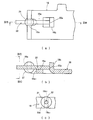
- FIG. 2 shows a part of the reed switch unit shown in FIG. 2, (a) is a plan view, (b) is a sectional view taken along line IIIB-IIIB in (a), and (c) is taken along line IIIC-IIIC in (b). It is sectional drawing which follows.
- FIG. 1 is a sectional view schematically showing a reservoir tank provided with an example of an embodiment of a liquid level detector according to the present invention. As shown in FIG. 1, a reservoir tank 1 of this example is attached to a known tandem master cylinder 2 of a hydraulic brake device.
- the reservoir tank 1 has a resin container 3.
- a primary hydraulic fluid storage chamber 4 that stores hydraulic fluid
- a secondary hydraulic fluid storage chamber 5 that similarly stores hydraulic fluid
- a liquid level detector 6 that detects the level of hydraulic fluid in the reservoir tank 1.
- the hydraulic fluid is supplied to the primary hydraulic fluid storage chamber 4 and the secondary hydraulic fluid storage chamber 5, and the hydraulic fluid supply port 7 closed by the cap 7 a and the primary hydraulic fluid storage chamber 4 are connected to the tandem master cylinder 2.
- the primary communication port 8 that supplies hydraulic fluid to the primary fluid chamber (not shown) and the secondary hydraulic fluid storage chamber 5 that supplies hydraulic fluid to the secondary fluid chamber (not shown) of the tandem master cylinder 2 are supplied.
- a secondary communication port 9 is provided.
- the liquid level detector 6 includes a float 11 that can be moved up and down in FIG. 1, a magnet 12 that is provided at the lower end of the float 11, a float guide portion 13 that includes a cylindrical partition that guides the float 11,
- the container 3 is provided with a switch accommodating portion 14 provided in a region in the float guide portion 13 at the lower end of the container 3 and a normally open type reed switch unit 15 accommodated in the switch accommodating portion 14.
- the primary hydraulic fluid storage chamber 4 and the secondary hydraulic fluid storage chamber 5 are partially partitioned by a partition wall, but communicate with each other through an opening formed in the partition wall. Further, the primary hydraulic fluid storage chamber 4 and the secondary hydraulic fluid storage chamber 5 are always in communication with the interior 13 a of the float guide portion 13 by a slit or the like formed in the float guide portion 13. Therefore, the liquid level of the hydraulic fluid in the primary hydraulic fluid storage chamber 4 and the secondary hydraulic fluid storage chamber 5 and the hydraulic fluid level in the interior 13a of the float guide part 13 move up and down in conjunction with each other, and are always at the same level. Become.
- the communication structure of the primary hydraulic fluid storage chamber 4, the secondary hydraulic fluid storage chamber 5, and the float guide portion 13 of the liquid level detector 6 is not limited to this, and any communication mechanism of a conventionally known reservoir tank can be used. It may be a structure.
- the reed switch unit 15 of this example is molded with a resin and the liquid level detector 6 is electrically connected to a liquid level display device or a liquid level alarm device (not shown).
- a unit body 18 having conductive first and second terminals 16 and 17 for connection, and a first body made of a conductive material such as aluminum extending from the unit body 18 and electrically conducting to the first terminal 16.
- 1 terminal 19 extending from the unit body 18 and electrically connected to the second terminal 17 is connected to the second terminal 20 and the first terminal 19 made of the same conductive material as the first terminal 19 by soldering 21.
- the extending directions of the first and second terminals 19 and 20 are set to be parallel or substantially parallel to each other and in the same direction.
- the first and second lead portions 22 and 24 are made of the same material and the same diameter conductive wire. These first and second lead portions 22 and 24 extend on the same axis.
- the reed switch 25 includes a first switch contact 26 that is electrically connected to the first lead portion 22, a second switch contact 27 that is electrically connected to the second lead portion 24, the first and first switches.
- the glass tube 28 which accommodates the two switch contacts 26 and 27 is provided. In that case, the first lead portion 22 extends from the glass tube 28 toward the unit body 18, and the second lead portion 24 extends from the glass tube 28 to the opposite side of the first lead portion 22. Therefore, the second terminal 20 is also extended to the opposite side of the first lead portion 22 with respect to the glass tube 28.
- the first terminal 19 has a lead placement portion 19a on which the first lead portion 22 is placed, and a first lead placed on the lead placement portion 19a.
- the first positioning portion 19b made of a stopper wall for positioning the tip 22a of the portion 22 in the axial direction of the first lead portion 22, and the first lead portion 22 placed on the lead placement portion 19a.
- Second positioning portions 19c that are positioned in a direction orthogonal to or substantially orthogonal to the extending direction (axial direction) of the first terminal 19 are integrally provided. In that case, both the first and second positioning portions 19b, 19c are bent and projected at a right angle or a substantially right angle with respect to the lead placement portion 19a.
- the second positioning portion 19c has a width (the length in the left-right direction in FIG. 3C) that allows the first lead portion 22 to be positioned in a direction perpendicular or substantially perpendicular to the axial direction of the first lead portion 22. having a first open groove 19c 1 that is configured to.
- the first open groove 19c 1 is extended to the lead mounting portion 19a.
- the first lead portion 22 is positioned in the same direction by passing through the first opening groove 19c 1 and is fixed to the second positioning portion 19c by soldering.
- the second lead portion 24 is perpendicular to or substantially perpendicular to the extending direction (axial direction) of the second lead portion 24 at the distal end portion of the second terminal 20.
- the 3rd positioning part 20a positioned in the direction to perform is provided.
- the third positioning portion 20 a is projected and bent at a right angle or a substantially right angle with respect to the axial direction of the second terminal 20.
- the third positioning portion 20a has a width (length in the left-right direction in FIG. 2C) set to a size that positions the second lead portion 24 in a direction perpendicular or substantially perpendicular to the axial direction of the second lead portion 24.
- the placement position of the bottom portion of the second opening groove 20a 1 and the placement position of the lead placement portion 19a are set on the same plane, and the width direction of the first and second opening grooves 19c 1 and 20a 1 is set. Each center is set on the same axis.
- the second lead portion 24 is fixed with the positioning of the same direction it is by penetrating the second open groove 20a 1, the third positioning portion 20a by soldering.
- the portion 20b of the second terminal 20 facing the glass tube 28 is formed as an elongated strip-shaped flat plate, and a pair of protective walls 20c and 20d for protecting the glass tube 28 are provided on both side edges of the portion 20b with respect to the portion 20b. It stands upright or almost at right angles.
- the first lead portion 22 is positioned on the second positioning portion 19c and placed on the lead placement portion 19a and is positioned on the first positioning portion 19b in the axial direction, and the second lead portion 24 is placed on the third positioning portion.
- the glass tube 28 of the reed switch 25 is separated from both the portion 20b of the second terminal 20 and the protective walls 20c and 20d.
- the glass tube 28 is part of the second terminal 20 and the protective walls 20c, 20d. It is set to a size that does not contact any of the above. Therefore, it is possible to prevent the glass tube 28 from being loaded from the second terminal 20.
- the liquid level detector 6 is attached to the reservoir tank 1 so that the reed switch 25 is positioned in the switch accommodating portion 14 of the reservoir tank 1.
- the float 11 and the magnet 12 guide the float guide part 13 in accordance with the change due to the rise of the liquid level. Then, it moves upward and moves away from the reed switch 25. Thereby, the magnetic force of the magnet 12 exerted on the reed switch 25 is reduced, and the first and second switch contacts 26 and 27 are separated from each other as shown in FIG. 2B, and the reed switch 25 is turned off. Therefore, a liquid level display device or a liquid level alarm device (not shown) does not operate.
- the first positioning portion 19b formed of a stopper wall for positioning the first lead portion in the axial direction is provided in the first terminal 19 and is not provided in the resin molded unit main body 18. .
- the first lead portion 22 is positioned in the axial direction on the first positioning portion 19b and positioned on the second positioning portion 19c and placed on the lead placement portion 19a, and the second lead portion 24 is placed on the third positioning portion 19a.
- the reed switch 25 is attached by positioning and mounting on 20a.
- the bent switch is not caulked and the reed switch is not attached. Therefore, when the reed switch 25 is attached, the reed switch 25 is moved from a predetermined position. The shift can be suppressed, and the reed switch 25 can be fixed at a predetermined position with higher accuracy. As a result, variation in the liquid level detection performance of the reed switch 25 can be suppressed.
- the length of the first and second lead portions 22, 24 in the axial direction can be arbitrarily set. It becomes possible to set, and the length of the first lead portion 22 in the axial direction can be increased. Therefore, the positions of the soldering 21 and 23 to the second and third positioning portions 19c and 20a of the first and second lead portions 22 and 24 can be moved away from the glass tube 28 of the reed switch 25 as compared with the conventional case. It becomes.
- lead-free solder that does not use lead in solder has been demanded in recent years, but such lead-less solder has a higher solder temperature than lead solder. Therefore, according to the liquid level detector 6 of this example, since the influence of heat due to soldering on the reed switch 25 can be suppressed, such lead-free solder is more effectively employed without affecting the reed switch 25. It becomes possible to do.
- the length of the first lead portion 22 can be arbitrarily set. This eliminates the need to previously cut the lead portion into a predetermined length as described in Japanese Patent No. 4088399. Accordingly, the switch performance of the reed switch 25 due to the cutting of the first lead portion 22 can be suppressed, and the cutting work is eliminated and the number of work steps is reduced, so that the cost can be reduced accordingly.
- first and second positioning portions 19b and 19c are provided integrally with the first terminal 19, there is no need to further cut the first lead portion 22, and the axis of the first lead portion 22 Positioning in a direction and positioning in a direction orthogonal or substantially orthogonal to the axial direction can be performed with higher accuracy.
- the reservoir tank 1 of this example since the liquid level detector 6 of this example is provided, a predetermined amount of hydraulic fluid can be reliably stored in the reservoir tank 1, and the reservoir tank 1 Thus, it is possible to reliably and stably operate a hydraulic actuator such as a hydraulic brake device.
- liquid level detector 6 and the reservoir tank 1 in this example are the same as those of a conventionally known liquid level detector and reservoir tank.
- the liquid level detector according to the present invention can be suitably used for a liquid level detector that detects a liquid level of a working fluid such as a reservoir tank with a reed switch.
- the reservoir tank according to the present invention can be suitably used for a reservoir tank that needs to always store a predetermined amount of hydraulic fluid that operates a hydraulic actuator such as a hydraulic brake device.
Landscapes
- Physics & Mathematics (AREA)
- Fluid Mechanics (AREA)
- General Physics & Mathematics (AREA)
- Level Indicators Using A Float (AREA)
Abstract
本発明の液面検出器(6)はリードスイッチユニット(15)を有する。このリードスイッチユニット(15)は、ユニット本体(18)と、ユニット本体(18)から延設された第1ターミナル(19)と、リードスイッチ(25)と第1ターミナル(19)とを導電可能に接続する第1リード部(22)とを少なくとも備える。第1ターミナル(19)は、第1リード部(22)の先端(22a)が当接することで第1リード部(22)を軸線方向に位置決めする第1位置決め部(19b)と、第1リード部(22)を軸線方向と直交またはほぼ直交する方向に位置決めする第2位置決め部(19c)と一体に有する。
Description
本発明は、液圧を利用した液圧ブレーキ装置等の液圧作動装置におい作動液を貯留するリザーバタンク等に用いられてリードスイッチにより作動液の液面を検出する液面検出器およびこれを備えたリザーバタンクの技術分野に関するものである。
従来、自動車等の車両においては、液圧を利用した液圧作動装置として液圧ブレーキ装置を採用した車両がある。この液圧ブレーキ装置には、液圧を発生させるマスタシリンダに供給する作動液を貯留するリザーバタンクが用いられている。
マスタシリンダが液圧必要時に液圧を発生するためには、リザーバタンク内に所定液量の作動液が貯留されている必要がある。作動液の液量を確認するため、一般にリザーバタンクには液面検出器が設けられている。この液面検出器は、リザーバタンク内の液量が所定液量より少なくなると、リザーバタンク内の作動液の液面が警告表示要の液面のレベル(MIN)より下回るため、この液面レベル低下を検出して液量表示装置(あるいは、液量警報装置)に表示(警報)させるようになっている。この液量表示(警報)装置の表示(警報)により、リザーバタンク内に作動液が少なくなっていることが認知される。そして、リザーバタンク内に作動液が補給されてリザーバタンク内の液量が所定液量以上に確保される。
従来のリザーバタンクの液面検出器として、リードスイッチを用いた液面検出器が、特開平7-220817号公報および特許第4088399号公報において知られている。特開平7-220817号公報に記載の液面検出器では、リードスイッチの周囲が、コネクタ本体と一体の樹脂製のリード金具被覆部に形成されたリブによって囲まれており、このリブによってリードスイッチが位置決めされている。
ところで、この種のリードスイッチは、一般にスイッチ接点がガラス管内に封入されて構成されている。しかし、特開平7-220817号公報に記載の液面検出器では、リードスイッチがリブによって位置決めされることから、リードスイッチのガラス管がリブに当接している。このようなリードスイッチが車両に搭載された場合、特許第4088399号公報に記載されているように、車両からの振動や作動液の温度変化等に基づく熱影響によりガラス管がリブから繰り返し負荷を受け、ガラス管に繰り返し応力が生じるという問題が考えられる。また、この液面検出器では、リードスイッチがコネクタ本体と一体のリード金具被覆部にガラス管を基準として取り付けられる。しかし、ガラス管はそれ自体寸法にばらつきがあるため、ガラス管を基準とするリードスイッチの取付では、リードスイッチのスイッチ接点が高精度に位置決めすることが難しいという問題が考えられる。
そこで、特許第4088399号公報に記載の液面検出器では、リードスイッチのリード部をユニット本体に設けられたターミナルの載置部に載置するとともに、このリード部を予め所定長さに切断した状態で、このリード部の先端をユニット本体に設けたストッパ壁に当接させてリードスイッチを軸方向に位置決めし、リード部を、ターミナルに設けた折曲片を熱かしめにより折り曲げ、リード部をこの折曲片と載置部との間にリードスイッチのガラス管がユニット本体に当接しないようにして挟持している。これにより、前述の特開平7-220817号公報に記載の液面検出器における振動や熱影響によりリブがガラス管に繰り返し負荷を加えることを抑制することができるとともに、リードスイッチのスイッチ接点をより高精度に位置決めすることが可能となる。
しかしながら、特許第4088399号公報に記載の液面検出器では、ストッパ壁が設置部とともに樹脂製のユニット本体に一体に形成されるので、設置部を成形する際にストッパ壁も同時に成形する必要がある。また、ユニット本体の樹脂成形の際、ばりが生じないようにする必要がある。このため、ユニット本体の成形のための金型が複雑な形状になり、コストが高くなってしまうという問題が考えられる。この問題は、特開平7-220817号公報に記載の液面検出器にも存在する。
また、折曲片の熱かしめ時、所定位置に置かれたリードスイッチに触れることでリード部が微小に移動して、リードスイッチが所定位置からずれて固定されてしまうことが考えられる。このように、リードスイッチが所定位置からずれて固定されると、リードスイッチの液面検知性能にばらつきが生じてしまうおそれがある。特に、リードスイッチの2本のリード部がそれぞれ折曲片により固定されるが、その場合、各リード部は、リードスイッチがユニット本体に当接しない状態で各折曲片をともに同一方向に折り曲げて固定されるため、リードスイッチがより一層所定位置からずれるおそれがある。
更に、各折曲片はリードスイッチのガラス管の近傍位置に配設されるため、各折曲片の熱かしめ時に、リードスイッチが熱かしめによる熱の影響を受けるばかりでなく、ガラス管に触れてしまうおそれがある。
本発明の目的は、ユニット本体の成形のための金型の形状をより簡単にしてコストを低減するとともにリードスイッチをより高精度に位置決めし、しかもリードスイッチの取付時における熱の影響およびガラス管への接触を抑制することのできる液面検出器およびこれを備えたリザーバタンクを提供することである。
本発明の目的を達成するために、本発明に係る液面検出器は、作動液の液面の変化に応じて移動するフロートと、前記フロートに設けられたマグネットと、前記マグネットによりオン・オフされるリードスイッチを有するリードスイッチユニットとを少なくとも備え、前記リードスイッチユニットが、ユニット本体と、前記ユニット本体から延設されたターミナルと、前記リードスイッチと前記ターミナルとを導電可能に接続するリード部とを少なくとも有する液面検出器において、前記ターミナルが前記リード部を軸線方向に位置決めする第1位置決め部を一体に有することを特徴としている。
また、本発明に係る液面検出器は、前記ターミナルが前記リード部を軸線方向と直交またはほぼ直交する方向に位置決めする第2位置決め部を一体に有することを特徴としている。
一方、本発明に係るリザーバタンクは、作動液を貯留する容器と、前記容器内の作動液の液面を検出する液面検出器とを少なくとも備えたリザーバタンクにおいて、前記液面検出器が、前述の本発明の液面検出器のいずれか1つであることを特徴としている。
このように構成された本発明に係る液面検出器によれば、リード部を軸線方向に位置決めする第1位置決め部をターミナルに一体に設けており、ユニット本体には設けていない。これにより、ユニット本体を例えば樹脂等で成形する際に第1位置決め部もユニット本体と同時に成形しなくて済むようになる。したがって、ユニット本体の成形のための金型をより簡単な形状にすることが可能となり、コストを低減することができる。
また、軸線方向と直交またはほぼ直交する方向に位置決めする第2位置決め部をターミナルに一体に設けている。これにより、リード部を第1位置決め部で軸線方向に位置決めしてターミナルに載置しかつ第2位置決め部で軸線方向と直交またはほぼ直交する方向に位置決めすることができる。したがって、前述の特許第4088399号公報に記載の液面検出器のように折曲片を熱かしめしてリードスイッチを取り付けることがないので、リードスイッチの取付時にリードスイッチが所定位置からずれることを抑制でき、リードスイッチを所定位置に、より高精度に固定することが可能となる。その結果、リードスイッチの液面検知性能のばらつきを抑制できる。
更に、ターミナルに設けられた第1位置決め部でリード部を軸線方向に位置決めしかつリード部を第2位置決め部に固定しているので、リード部の軸線方向の長さを長くすることが可能となる。したがって、リード部の固定に半田付けを用いた場合、リード部の第1および第2位置決め部への半田付けの位置を、リードスイッチのガラス管から従来に比べて遠ざけることが可能となる。これにより、リード部の半田付けの際に、リードスイッチに対する半田付けによる熱の影響を抑制できるとともに、ガラス管に触れる可能性を低減できる。特に、近年半田に鉛を用いない鉛レス半田が求められているが、このような鉛レス半田では、半田温度が鉛半田に比べて高くなる。したがって、本発明の液面検出器によれば、リードスイッチに対する半田付けによる熱の影響を抑制できることから、このような鉛レス半田をリードスイッチに影響させることなく、より効果的に採用することが可能となる。
更に、第1位置決め部をターミナルに設けていてユニット本体には設けていないことから、リード部の長さを任意に設定可能となる。これにより、前述の特許第4088399号公報に記載のようにリード部を予め所定長さに切断する必要がなくなる。したがって、リード部の切断によるリードスイッチのスイッチ性能の低下を抑制できるとともに、切断作業がなくなり作業工数が削減されるので、その分、コストを低減できる。特に、第1および第2位置決め部の両方をターミナルにこれと一体に設けているので、リード部の切断をより一層行う必要がないとともに、リード部の軸線方向の位置決めおよび軸線方向と直交またはほぼ直交する方向の位置決めをより一層高精度に行うことが可能となる。
一方、本発明に係るリザーバタンクによれば、本発明の液面検出器を備えているので、リードスイッチの液面検知性能のばらつきを抑制できることからリザーバタンク内に所定液量の作動液を確実に貯留することができる。したがって、リザーバタンク内の作動液を利用する、例えば液圧ブレーキ装置等の液圧作動装置を確実にかつ安定して作動させることが可能となる。
以下、図面を用いて、本発明を実施するための最良の形態について説明する。
図1は本発明に係る液面検出器の実施の形態の一例を備えるリザーバタンクを模式的に示す断面図である。図1に示すように、この例のリザーバタンク1は、液圧ブレーキ装置の公知のタンデムマスタシリンダ2に取り付けられている。
リザーバタンク1は樹脂製の容器3を有する。この容器3内には、作動液を貯留するプライマリ作動液貯留室4、同じく作動液を貯留するセカンダリ作動液貯留室5、リザーバタンク1内の作動液の液面を検出する液面検出器6が設けられている。また、容器3には、プライマリ作動液貯留室4およびセカンダリ作動液貯留室5に作動液を供給するとともにキャップ7aにより閉塞される作動液供給口7、プライマリ作動液貯留室4をタンデムマスタシリンダ2のプライマリ液室(不図示)へ連通して作動液を供給するプライマリ連通口8、およびセカンダリ作動液貯留室5をタンデムマスタシリンダ2のセカンダリ液室(不図示)へ連通する作動液を供給するセカンダリ連通口9が設けられている。
液面検出器6は、図1において上下動可能に配設されたフロート11、このフロート11の下端部に設けられたマグネット12、フロート11をガイドする筒状の隔壁からなるフロートガイド部13、容器3の下端にフロートガイド部13内の領域に位置して設けられたスイッチ収容部14、およびこのスイッチ収容部14に収容されるノーマルオープン型のリードスイッチユニット15を備えている。
プライマリ作動液貯留室4、セカンダリ作動液貯留室5は互いに隔壁で部分的に区画されているが、隔壁に形成された開口等により互いに連通している。また、プライマリ作動液貯留室4およびセカンダリ作動液貯留室5がフロートガイド部13に形成されたスリット等によりフロートガイド部13の内部13aに常時連通している。したがって、プライマリ作動液貯留室4およびセカンダリ作動液貯留室5の各作動液の液面とフロートガイド部13の内部13aの作動液の液面とが連動して上下動し、常時互いに同じレベルとなる。なお、プライマリ作動液貯留室4、セカンダリ作動液貯留室5、および液面検出器6のフロートガイド部13の連通構造は、これに限定されることはなく、従来公知のリザーバタンクのいずれの連通構造でもよい。
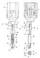
図2(a)ないし(c)に示すように、この例のリードスイッチユニット15は、樹脂モールド成形されるとともに液面検出器6を図示しない液面表示装置あるいは液面警報装置に電気的に接続するための導電性の第1および第2端子16,17を有するユニット本体18、このユニット本体18から延設されるとともに第1端子16に電気的に導通するアルミニウム等の導電材からなる第1ターミナル19、ユニット本体18から延設されるとともに第2端子17に電気的に導通する、第1ターミナル19と同じ導電材からなる第2ターミナル20、第1ターミナル19に半田付け21で接続された導電性の第1リード部22、第2ターミナル20に半田付け23で接続された導電性の第2リード部24、第1および第2リード部22,24に導電可能に接続されたリードスイッチ25を備えている。各半田付け21,23には、鉛を用いない鉛レス半田が採用されている。
第1および第2ターミナル19,20の延設方向は互いに平行またはほぼ平行にかつ同じ向きに設定されている。また、第1および第2リード部22,24は同じ材質で同径の導電線から形成されている。これらの第1および第2リード部22,24は同一軸線上に延設されている。更に、リードスイッチ25は、第1リード部22に電気的に導通可能に接続された第1スイッチ接点26、第2リード部24に電気的に接続された第2スイッチ接点27、第1および第2スイッチ接点26,27を収容するガラス管28を備えている。その場合、第1リード部22はガラス管28からユニット本体18側に向かって延出し、また、第2リード部24はガラス管28から第1リード部22と反対側に延出している。したがって、第2ターミナル20もガラス管28に関し第1リード部22と反対側まで延出されている。
図3(a)ないし(c)に示すように、第1ターミナル19には、第1リード部22が載置されるリード載置部19a、リード載置部19aに載置された第1リード部22の先端22aをこの第1リード部22の軸線方向に位置決めするストッパー壁からなる第1位置決め部19b、およびリード載置部19aに載置された第1リード部22を第1リード部22の延設方向(軸線方向)と直交またはほぼ直交する方向に位置決めする第2位置決め部19cがそれぞれ第1ターミナル19に一体に設けられている。その場合、第1および第2位置決め部19b,19cは、ともにリード載置部19aに対して直角またはほぼ直角に折り曲げられて突設されている。また、第2位置決め部19cは、幅(図3(c)において左右方向の長さ)が第1リード部22を第1リード部22の軸方向と直交またはほぼ直交する方向に位置決め可能な大きさに設定された第1開口溝19c1を有する。この第1開口溝19c1はリード載置部19aまで延設されている。 第1リード部22は第1開口溝19c1を貫通することで同方向の位置決めがされるとともに、半田付けで第2位置決め部19cに固定される。
一方、図2(b)および(c)に示すように、第2ターミナル20の先端部には、第2リード部24を第2リード部24の延設方向(軸線方向)と直交またはほぼ直交する方向に位置決めする第3位置決め部20aが設けられている。その場合、第3位置決め部20aは、第2ターミナル20の軸線方向に対して直角またはほぼ直角に折り曲げられて突設されている。第3位置決め部20aは、幅(図2(c)において左右方向の長さ)が第2リード部24を第2リード部24の軸方向と直交またはほぼ直交する方向に位置決めする大きさに設定されるとともに底部で第2リード部24を載置する第2開口溝20a1を有する。第2開口溝20a1の底部の載置位置とリード載置部19aの載置位置とは同一平面上に設定されているとともに、第1および第2開口溝19c1,20a1の幅方向の各中心は同一軸線上に設定されている。第2リード部24は第2開口溝20a1を貫通することで同方向の位置決めがされるとともに、半田付けで第3位置決め部20aに固定される。
ガラス管28に対向する第2ターミナル20の部分20bは細長い帯状平板で形成されており、この部分20bの両側縁には、ガラス管28を保護する一対の保護壁20c,20dが部分20bに対して直角またはほぼ直角に立設されている。そして、第1リード部22が第2位置決め部19cに位置決めされてリード載置部19aに載置されかつ第1位置決め部19bに軸線方向に位置決めされるとともに、第2リード部24が第3位置決め部20aに位置決めされて載置された状態では、リードスイッチ25のガラス管28は、第2ターミナル20の部分20bおよび保護壁20c,20dのいずれからも離間している。その場合これらの離間量は、リードスイッチユニット15が車両からの振動や作動液の温度変化等に基づく熱影響を受けても、ガラス管28が第2ターミナル20の部分20bおよび保護壁20c,20dのいずれにも接触しない程度の大きさに設定されている。したがって、ガラス管28が第2ターミナル20から負荷を加えられることが抑制される。
この液面検出器6は、リードスイッチ25がリザーバタンク1のスイッチ収容部14内に位置するようにしてリザーバタンク1に取り付けられる。そして、液面検出器6のフロートガイド部13の内部13aの作動液の液面が上昇して変化すると、フロート11およびマグネット12がこの液面の上昇による変化に応じてフロートガイド部13にガイドされて上昇移動しリードスイッチ25から遠ざかる。これにより、リードスイッチ25に及ぼすマグネット12の磁力が小さくなり、図2(b)に示すように第1および第2スイッチ接点26,27が互いに離間し、リードスイッチ25がオフとなる。したがって、図示しない液量表示装置あるいは液量警報装置は作動しない。
また、フロートガイド部13の内部13aの作動液の液面が下降して変化すると、フロート11およびマグネット12がこの液面の下降による変化に応じてフロートガイド部13にガイドされて下降移動しリードスイッチ25に接近する。プライマリ作動液貯留室4およびセカンダリ作動液貯留室5の作動液の液面が下降して警告表示要の液面のレベル(MIN)になると、マグネット12の磁力により第1および第2スイッチ接点26,27が互いに接触し、リードスイッチ25がオンとなる。したがって、液量表示装置あるいは液量警報装置は、リザーバ1内の作動液量が必要最少限の作動液量に近くなったことを表示あるいは警報する。
この例の液面検出器6によれば、第1リード部を軸線方向に位置決めするストッパ壁からなる第1位置決め部19bを第1ターミナル19に設けて、樹脂成形のユニット本体18に設けていない。これにより、ユニット本体18を樹脂成形する際に第1位置決め部19bも同時に成形しなくて済むようになる。したがって、ユニット本体18の成形のための金型をより簡単な形状にすることが可能となり、コストを低減することができる。
また、第1リード部22を第1位置決め部19bに軸線方向に位置決めしかつ第2位置決め部19cに位置決めしてリード載置部19aに載置するとともに、第2リード部24を第3位置決め部20aに位置決めして載置することで、リードスイッチ25を取り付けている。これにより、前述の特許第4088399号公報に記載の液面検出器のように折曲片を熱かしめしてリードスイッチを取り付けることがないので、リードスイッチ25の取付時にリードスイッチ25が所定位置からずれることを抑制でき、リードスイッチ25を所定位置に、より高精度に固定することが可能となる。その結果、リードスイッチ25の液面検知性能のばらつきを抑制できる。
更に、第1ターミナル19に設けられた第1位置決め部19bで第1リード部22を軸線方向に位置決めしているので、第1および第2リード部22,24の軸線方向の長さを任意に設定することが可能となり、第1リード部22の軸線方向の長さを長くすることができる。したがって、第1および第2リード部22,24の第2および第3位置決め部19c,20aへの半田付け21,23の位置を、リードスイッチ25のガラス管28から従来に比べて遠ざけることが可能となる。これにより、第1および第2リード部22,24の半田付け21,23の際に、リードスイッチ25に対する半田付けによる熱の影響を抑制できるとともに、ガラス管28に触れる可能性を低減できる。特に、近年半田に鉛を用いない鉛レス半田が求められているが、このような鉛レス半田では、半田温度が鉛半田に比べて高くなる。したがって、この例の液面検出器6によれば、リードスイッチ25に対する半田付けによる熱の影響を抑制できることから、このような鉛レス半田をリードスイッチ25に影響させることなく、より効果的に採用することが可能となる。
更に、第1位置決め部19bを第1ターミナル19に設けていてユニット本体18には設けていないことから、第1リード部22の長さを任意に設定可能となる。これにより、特許第4088399号公報に記載のようにリード部を予め所定長さに切断する必要がなくなる。したがって、第1リード部22の切断によるリードスイッチ25のスイッチ性能の低下を抑制できるとともに、切断作業がなくなり作業工数が削減されるので、その分、コストを低減できる。特に、第1および第2位置決め部19b,19cを第1ターミナル19にこれと一体に設けているので、第1リード部22の切断をより一層行う必要がないとともに、第1リード部22の軸線方向の位置決めおよび軸線方向と直交またはほぼ直交する方向の位置決めをより一層高精度に行うことが可能となる。
更に、この例のリザーバタンク1によれば、この例の液面検出器6を備えているので、リザーバタンク1内に所定液量の作動液を確実に貯留することができ、リザーバタンク1内の作動液を利用する、例えば液圧ブレーキ装置等の液圧作動装置を確実にかつ安定して作動させることが可能となる。
この例の液面検出器6およびリザーバタンク1の他の構成および他の作用効果は、いずれも従来公知の液面検出器およびリザーバタンクと同様である。
なお、本発明は、前述の例に限定されることはなく、特許請求の範囲に記載された事項の範囲内で、種々の設計変更が可能である。
本発明に係る液面検出器は、リザーバタンク等の作動液の液面をリードスイッチにより検出する液面検出器に好適に利用することができる。
また、本発明に係るリザーバタンクは、液圧ブレーキ装置等の液圧作動装置を作動させる作動液を常時所定液量貯留する必要のあるリザーバタンクに好適に利用することができる。
また、本発明に係るリザーバタンクは、液圧ブレーキ装置等の液圧作動装置を作動させる作動液を常時所定液量貯留する必要のあるリザーバタンクに好適に利用することができる。
Claims (3)
- 作動液の液面の変化に応じて移動するフロートと、前記フロートに設けられたマグネットと、前記マグネットによりオン・オフされるリードスイッチを有するリードスイッチユニットとを少なくとも備え、
前記リードスイッチユニットは、ユニット本体と、前記ユニット本体から延設されたターミナルと、前記リードスイッチと前記ターミナルとを導電可能に接続するリード部とを少なくとも有する液面検出器において、
前記ターミナルは前記リード部を軸線方向に位置決めする第1位置決め部を一体に有することを特徴とする液面検出器。 - 前記ターミナルは前記リード部を軸線方向と直交またはほぼ直交する方向に位置決めする第2位置決め部を一体に有し、前記リード部は前記第2位置決め部に固定されることを特徴とする請求項1に記載の液面検出器。
- 作動液を貯留する容器と、前記容器内の作動液の液面を検出する液面検出器とを少なくとも備えたリザーバタンクにおいて、
前記液面検出器は、請求項1または2に記載の液面検出器であることを特徴とするリザーバタンク。
Applications Claiming Priority (2)
| Application Number | Priority Date | Filing Date | Title |
|---|---|---|---|
| JP2009141969 | 2009-06-15 | ||
| JP2009-141969 | 2009-06-15 |
Publications (1)
| Publication Number | Publication Date |
|---|---|
| WO2010146823A1 true WO2010146823A1 (ja) | 2010-12-23 |
Family
ID=43356156
Family Applications (1)
| Application Number | Title | Priority Date | Filing Date |
|---|---|---|---|
| PCT/JP2010/003927 Ceased WO2010146823A1 (ja) | 2009-06-15 | 2010-06-14 | 液面検出器およびこれを備えたリザーバタンク |
Country Status (1)
| Country | Link |
|---|---|
| WO (1) | WO2010146823A1 (ja) |
Cited By (2)
| Publication number | Priority date | Publication date | Assignee | Title |
|---|---|---|---|---|
| WO2017081957A1 (ja) * | 2015-11-09 | 2017-05-18 | 株式会社デンソー | 液面検出装置 |
| CN109437082A (zh) * | 2018-10-31 | 2019-03-08 | 黄石市华顺机电股份有限公司 | 一种定液位自切断流体加注枪 |
Citations (1)
| Publication number | Priority date | Publication date | Assignee | Title |
|---|---|---|---|---|
| JP2003317877A (ja) * | 2002-04-19 | 2003-11-07 | Asahi Matsushita Electric Works Ltd | リードスイッチ保持金具付きコネクタ |
-
2010
- 2010-06-14 WO PCT/JP2010/003927 patent/WO2010146823A1/ja not_active Ceased
Patent Citations (1)
| Publication number | Priority date | Publication date | Assignee | Title |
|---|---|---|---|---|
| JP2003317877A (ja) * | 2002-04-19 | 2003-11-07 | Asahi Matsushita Electric Works Ltd | リードスイッチ保持金具付きコネクタ |
Cited By (4)
| Publication number | Priority date | Publication date | Assignee | Title |
|---|---|---|---|---|
| WO2017081957A1 (ja) * | 2015-11-09 | 2017-05-18 | 株式会社デンソー | 液面検出装置 |
| JP2017090206A (ja) * | 2015-11-09 | 2017-05-25 | 株式会社デンソー | 液面検出装置 |
| CN109437082A (zh) * | 2018-10-31 | 2019-03-08 | 黄石市华顺机电股份有限公司 | 一种定液位自切断流体加注枪 |
| CN109437082B (zh) * | 2018-10-31 | 2024-04-12 | 黄石市华顺机电股份有限公司 | 一种定液位自切断流体加注枪 |
Similar Documents
| Publication | Publication Date | Title |
|---|---|---|
| US8813560B2 (en) | Fluid reservoir for a motor vehicle hydraulic brake system | |
| EP2023112B1 (en) | Pressure sensor | |
| US9362072B2 (en) | Magnetic float switch | |
| US8739526B2 (en) | Compensating reservoir for a hydraulic motor vehicle brake system | |
| KR101973835B1 (ko) | 액면검출장치 | |
| JPWO2017204065A1 (ja) | コンデンサ | |
| KR101945587B1 (ko) | 압력 센서 | |
| US9444196B2 (en) | Electrical connector | |
| WO2010146823A1 (ja) | 液面検出器およびこれを備えたリザーバタンク | |
| WO2014156531A1 (ja) | 電気接触子及び電気部品用ソケット | |
| US9435678B2 (en) | Liquid level detection device | |
| JP2017165120A (ja) | 電子制御装置 | |
| JP7533280B2 (ja) | ネジ保持構造、端子台、及び電気機器 | |
| JP2014139517A (ja) | 液面検出装置 | |
| JP6656819B2 (ja) | 端子台 | |
| CN115206720A (zh) | 杆操作装置 | |
| JP5995118B2 (ja) | 液面検出装置 | |
| JP2014016280A (ja) | 液温検出装置 | |
| JP2022149560A (ja) | 検出装置および検出システム | |
| JP7112642B2 (ja) | 液面検出装置 | |
| JP7533281B2 (ja) | ネジ保持構造、端子台、及び電気機器 | |
| JP6124050B2 (ja) | 液面検出装置 | |
| JP2005280444A (ja) | 車両用ブレーキ液圧制御装置 | |
| JP6400795B1 (ja) | 印刷回路基板 | |
| CN120035524A (zh) | 换挡装置 |
Legal Events
| Date | Code | Title | Description |
|---|---|---|---|
| 121 | Ep: the epo has been informed by wipo that ep was designated in this application |
Ref document number: 10789205 Country of ref document: EP Kind code of ref document: A1 |
|
| NENP | Non-entry into the national phase |
Ref country code: DE |
|
| 122 | Ep: pct application non-entry in european phase |
Ref document number: 10789205 Country of ref document: EP Kind code of ref document: A1 |
|
| NENP | Non-entry into the national phase |
Ref country code: JP |