WO2010143625A1 - 移動通信方法及びリレーノード - Google Patents
移動通信方法及びリレーノード Download PDFInfo
- Publication number
- WO2010143625A1 WO2010143625A1 PCT/JP2010/059689 JP2010059689W WO2010143625A1 WO 2010143625 A1 WO2010143625 A1 WO 2010143625A1 JP 2010059689 W JP2010059689 W JP 2010059689W WO 2010143625 A1 WO2010143625 A1 WO 2010143625A1
- Authority
- WO
- WIPO (PCT)
- Prior art keywords
- radio bearer
- bearer
- mobile station
- relay node
- radio
- Prior art date
- Legal status (The legal status is an assumption and is not a legal conclusion. Google has not performed a legal analysis and makes no representation as to the accuracy of the status listed.)
- Ceased
Links
Images


Classifications
-
- H—ELECTRICITY
- H04—ELECTRIC COMMUNICATION TECHNIQUE
- H04B—TRANSMISSION
- H04B7/00—Radio transmission systems, i.e. using radiation field
- H04B7/14—Relay systems
- H04B7/15—Active relay systems
- H04B7/155—Ground-based stations
-
- H—ELECTRICITY
- H04—ELECTRIC COMMUNICATION TECHNIQUE
- H04W—WIRELESS COMMUNICATION NETWORKS
- H04W72/00—Local resource management
- H04W72/50—Allocation or scheduling criteria for wireless resources
- H04W72/54—Allocation or scheduling criteria for wireless resources based on quality criteria
- H04W72/543—Allocation or scheduling criteria for wireless resources based on quality criteria based on requested quality, e.g. QoS
-
- H—ELECTRICITY
- H04—ELECTRIC COMMUNICATION TECHNIQUE
- H04W—WIRELESS COMMUNICATION NETWORKS
- H04W84/00—Network topologies
- H04W84/02—Hierarchically pre-organised networks, e.g. paging networks, cellular networks, WLAN [Wireless Local Area Network] or WLL [Wireless Local Loop]
- H04W84/04—Large scale networks; Deep hierarchical networks
- H04W84/042—Public Land Mobile systems, e.g. cellular systems
- H04W84/047—Public Land Mobile systems, e.g. cellular systems using dedicated repeater stations
Definitions
- the present invention relates to a mobile communication method and a relay node.
- an E-RAB (E-UTRAN) is used as a U-plane bearer between a mobile station UE and a gateway device S-GW (Serving-Gateway).
- Radio Access Bearer, bearer for mobile station UE is set
- Uu radio bearer (first radio bearer) is set between mobile station UE and relay node RN
- An Un radio bearer (second radio bearer) is set in between
- an S1 bearer is configured between the radio base station DeNB and the gateway device S-GW.
- the present invention has been made in view of the above-described problems, and provides a mobile communication method and a relay node capable of appropriately mapping an E-RAB, a Uu radio bearer, an Un radio bearer, and an S1 bearer. For the purpose.
- a first feature of the present invention is a mobile communication method, in which a mobile station transmits a bearer setting request signal for requesting to set a bearer for a predetermined QoS between the mobile station and a gateway device. And whether or not the second radio bearer for the predetermined QoS is set between the relay node and the radio base station according to the received bearer setup request signal. And when determining that the second radio bearer for the predetermined QoS is set, the first radio bearer for the predetermined QoS is set between the mobile station and the relay node. And the relay node generates and stores first context information associating the set first radio bearer for the predetermined QoS and the second radio bearer for the predetermined QoS. And the radio base station generates and stores second context information associating the second radio bearer for the predetermined QoS with the bearer for the predetermined QoS between the radio base station and the gateway device. And a step of performing.
- a second feature of the present invention is a relay node, which receives a bearer setting request signal for requesting to set a bearer for a predetermined QoS between the mobile station and the gateway device from the mobile station.
- a determination unit configured to determine whether or not the second radio bearer for the predetermined QoS is set with the radio base station, and the second radio bearer for the predetermined QoS is set.
- the mobile station side interface configured to set the first radio bearer for the predetermined QoS with the mobile station, and the set first radio bearer for the predetermined QoS
- a storage unit configured to generate and store context information for associating with the second radio bearer for the predetermined QoS.
- the present invention it is possible to provide a mobile communication method and a relay node capable of appropriately mapping an E-RAB, a Uu radio bearer, an Un radio bearer, and an S1 bearer.
- FIG. 1 is an overall configuration diagram of a mobile communication system according to a first embodiment of the present invention.
- FIG. 2 is a functional block diagram of the relay node according to the first embodiment of the present invention.
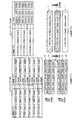
- FIG. 3 is a diagram for explaining a Uu radio bearer and an Un radio bearer set in the mobile communication system according to the first embodiment of the present invention.
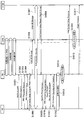
- FIG. 4 is a sequence diagram showing operations of the mobile communication system according to the first embodiment of the present invention.
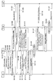
- FIG. 5 is a sequence diagram showing operations of the mobile communication system according to the first embodiment of the present invention.
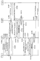
- FIG. 6 is a sequence diagram showing an operation of the mobile communication system according to the first modification of the first embodiment of the present invention.
- Mobile communication system according to the first embodiment of the present invention A mobile communication system according to a first embodiment of the present invention will be described with reference to FIGS.
- the mobile communication system is an LTE-Advanced mobile communication system, and as shown in FIG. 1, as a U-plane bearer, a mobile station UE, a gateway device S-GW, Between the mobile station UE and the relay node RN, a Uu radio bearer is set up in the first radio section between the mobile station UE and the relay node RN, and a second radio between the relay node RN and the radio base station DeNB. In the section, the Un radio bearer is set, and the S1 bearer is set between the radio base station DeNB and the gateway device S-GW.
- the mobile communication system is configured such that an E-RAB, a Uu radio bearer, an Un radio bearer, and an S1 bearer are mapped.
- the relay node RN includes a UE-side interface 11, a DeNB-side interface 12, a storage unit 13, and a determination unit 14.
- the UE side interface 11 functions as an interface with the mobile station UE
- the DeNB side interface 12 functions as an interface with the radio base station DeNB.
- the determination unit 14 receives, from the mobile station UE, “Attach Request” or “Service Request” requesting to set an E-RAB for the predetermined QoS between the mobile station UE and the gateway device S-GW In addition, it is configured to determine whether or not an Un radio bearer for predetermined QoS is set with the radio base station DeNB.
- the storage unit 13 is configured to store a UE context (RN), that is, first context information.
- RN UE context
- the storage unit 13 is configured to store information for mapping the Uu radio bearer for the predetermined QoS and the Un radio bearer for the predetermined QoS as the UE context (RN).
- the storage unit 13 of the relay node RN stores the UE context (RN), whereby a plurality of mobile stations UE # 0 to UE # n and relays Among a plurality of Uu radio bearers set with the node RN, each Uu radio bearer for a predetermined QoS set for a different mobile station UE is set between the relay node RN and the radio base station DeNB. To be mapped to Un radio bearers X to Z for predetermined QoS.
- the Uu radio bearer A0 for QoS # 0 that is set for the mobile station UE # 0 includes the identification information (CRNTI (UE # 0)) of the mobile station UE # 0 and the mobile station UE in the first radio section.
- the Uu radio bearer B0 for QoS # 0 includes the identification information (CRNTI (UE # n)) of the mobile station UE # n and the identification information (E-RAB) of the E-RAB of the mobile station UE # n in the first radio section. # 0) and Uu radio bearer identification information (DRB # 0).
- the Un radio bearer X for QoS # 0 includes identification information (CRNTI (RN)) of the relay node RN, identification information of E-RAB (E-RAB # 0) in the second radio section, and identification of the Un radio bearer. It is configured to be specified by information (DRB # 0).
- the Uu radio bearer A1 for QoS # 1 set for the mobile station UE # 0 and the Uu radio bearer B1 for QoS # 1 set for the mobile station UE # n. Are mapped to the Un radio bearer Y for QoS # 1.
- the Uu radio bearer A1 for QoS # 1 that is set for the mobile station UE # 0 includes the identification information (CRNTI (UE # 0)) of the mobile station UE # 0 and the mobile station UE in the first radio section.
- # 0 E-RAB identification information (E-RAB # 1) and Uu radio bearer identification information (DRB # 1) are configured to be specified and configured for mobile station UE # n
- the Uu radio bearer B1 for QoS # 1 includes the identification information (CRNTI (UE # n)) of the mobile station UE # n and the identification information (E-RAB) of the E-RAB of the mobile station UE # n in the first radio section. # 1) and Uu radio bearer identification information (DRB # 1).
- the Un radio bearer Y for QoS # 1 includes the identification information (CRNTI (RN)) of the relay node RN, the identification information (E-RAB # 1) of the E-RAB in the second radio section, and the identification of the Un radio bearer. It is configured to be specified by the information (DRB # 1).
- the Uu radio bearer A2 for QoS # 2 set for the mobile station UE # 0 includes the identification information (CRNTI (UE # 0)) of the mobile station UE # 0 and the mobile station UE in the first radio section. It is configured to be specified by the identification information (E-RAB # 2) of the E-RAB of # 0 and the identification information (DRB # 2) of the Uu radio bearer, and is set for the mobile station UE # n
- the Uu radio bearer B2 for QoS # 2 includes identification information (CRNTI (UE # n)) of the mobile station UE # n and identification information (E-RAB) of the E-RAB of the mobile station UE # n in the first radio section. # 2) and identification information (DRB # 2) of the Uu radio bearer.
- the Un radio bearer Z for QoS # 1 includes identification information (CRNTI (RN)) of the relay node RN, identification information of E-RAB (E-RAB # 2) in the second radio section, and identification of the Un radio bearer. It is configured to be specified by the information (DRB # 2).
- the radio base station DeNB stores the UE context (DeNB), so that the radio base station DeNB and the gateway device S-GW are connected.
- DeNB UE context
- each of the S1 bearers for the predetermined QoS set for different mobile stations UE # 0 to UE # n is mapped to the Un radio bearers X to Z for the predetermined QoS. It may be configured.
- the S1 bearer for QoS # 0 set for the mobile station UE # 0 and the S1 bearer for QoS # 0 set for the mobile station UE # n are the Un radio bearer X To be mapped to.
- the S1 bearer for QoS # 0 set for the mobile station UE # 0 is configured to be specified by the TEID # 0, and is for QoS # 0 set for the mobile station UE # n.
- the S1 bearer is configured to be identified by TEID # 3.
- the S1 bearer for QoS # 1 set for the mobile station UE # 0 and the S1 bearer for QoS # 1 set for the mobile station UE # n are mapped to the Un radio bearer Y. It is configured.
- the S1 bearer for QoS # 1 set for the mobile station UE # 0 is configured to be specified by TEID # 1, and is for QoS # 1 set for the mobile station UE # n.
- the S1 bearer is configured to be specified by TEID # 4.
- the S1 bearer for QoS # 2 set for the mobile station UE # 0 and the S1 bearer for QoS # 2 set for the mobile station UE # n are configured to be mapped to the Un radio bearer Z. Has been.
- the S1 bearer for QoS # 2 set for the mobile station UE # 0 is configured to be specified by the TEID # 2, and is for QoS # 2 set for the mobile station UE # n.
- the S1 bearer is configured to be specified by TEID # 5.
- step S1001 the mobile station UE transmits “RACH preamble” to the relay node RN, and in step S1002, the relay node RN moves according to the received “RACH preamble”. “RACH response” is transmitted to the station UE.
- step S1003 the mobile station UE transmits “RRC Connection Request” to the relay node RN.
- step S1004 the relay node RN responds to the received “RRC Connection Request” with respect to the mobile station UE. Send “RRC Connection Setup”.
- step S1005 the mobile station UE transmits “RRC Connection Setup Complete” including “Attach Request (E-RAB setting request signal for the mobile station UE)” to the relay node RN.
- SRB1 signaling radio bearer 1
- Attach Request is a NAS signal for requesting the gateway device S-GW to set an E-RAB for a predetermined QoS for the mobile station UE.
- step S1006 the relay node RN determines whether or not an Un radio bearer for a predetermined QoS is set with the radio base station DeNB.
- the relay node RN transmits the predetermined QoS Un radio bearer to the radio base station DeNB via the predetermined QoS. “Initial UE Message” including “Attach Request” is transmitted.
- the Un radio bearer for the predetermined QoS is an RN SRB1 (signaling radio bearer 1) or an RN SRB1 (signaling radio bearer 1) for transmitting a control signal set for the relay node RN.
- it may be an RN DRB (data radio bearer) for transmitting user data set for the relay node RN, or a UE common DRB set in common for a plurality of mobile stations UE. It may be.
- step S1007 the radio base station DeNB transmits the “Initial UE Message” to the gateway device S-GW, and authentication processing and security processing are performed between the mobile station UE and the gateway device S-GW.
- step S1008 the gateway device S-GW transmits “Initial Context Setup Request” including “Attach Accept” to the relay node RN in accordance with the received “Initial UE Message”.
- the relay node RN transmits “Security Mode Command” to the mobile station UE in step S1009, and transmits “RRC Connection Reconfiguration” in step S1010.
- the “RRC Connection Reconfiguration” is a Uu radio bearer setting request signal for the mobile station UE including an information element that requests to set the Uu radio bearer for the mobile station UE (DRB for UE).
- the mobile station UE transmits “Security Mode Complete” to the relay node RN in Step S1011.
- Step S1012 the “RRC Connection Reconfiguration Complete (Uu radio bearer setting completion signal for the mobile station UE)” is transmitted. Send.
- a Uu radio bearer for the mobile station UE is established.
- the relay node RN includes a predetermined QoS Uu radio bearer and a predetermined QoS Un radio bearer configured for the mobile station UE.
- a UE context (RN) to associate with is generated and stored.
- step S1015 the relay node RN transmits “RRC Connection Reconfiguration Complete (Un radio bearer setting completion signal for the mobile station UE)” to the gateway device S-GW via the radio base station DeNB.
- the radio base station DeNB generates and stores a UE context (DeNB) for associating a predetermined QoS Un radio bearer with a predetermined QoS S1 bearer set for the mobile station UE.
- DeNB UE context
- step S1017 the mobile station UE transmits “Attach Complete” to the exchange MME.
- step S1101 the mobile station UE transmits “RACH preamble” to the relay node RN, and in step S1102, the relay node RN moves according to the received “RACH preamble”. “RACH response” is transmitted to the station UE.
- step S1103 the mobile station UE transmits “RRC Connection Request” to the relay node RN.
- step S1104 the relay node RN responds to the received “RRC Connection Request” to the mobile station UE. Send “RRC Connection Setup”.
- step S1105 the mobile station UE transmits “RRC Connection Setup Complete” including “Attach Request (E-RAB setting request signal for the mobile station UE)” to the relay node RN.
- SRB1 signaling radio bearer 1
- Attach Request is a NAS signal for requesting the gateway device S-GW to set an E-RAB for a predetermined QoS for the mobile station UE.
- step S1106 the relay node RN determines whether or not an Un radio bearer for a predetermined QoS is set with the radio base station DeNB.
- the relay node RN DRB for transmitting user data set for the relay node RN ( “Initial UE Message” including “Attach Request” is transmitted to the radio base station DeNB via the data radio bearer.
- step S1107 the radio base station DeNB transmits the “Initial UE Message” to the gateway device S-GW, and in step S1108, authentication processing and security are performed between the mobile station UE and the gateway device S-GW.
- step S1109 the gateway device S-GW sends “Initial Context Setup Request” including “Attach Accept” to the radio base station DeNB according to the received “Initial UE Message”. Send.
- step S1110 the radio base station DeNB transmits “RRC Connection Reconfiguration” to the relay node RN.
- the “RRC Connection Reconfiguration” includes “Initial Context Setup Request (Attach Accept)” transmitted by the gateway device S-GW, and requests to set an unradio bearer (UE DRB) for a predetermined QoS. It is a setting request signal of the Un radio bearer including the element “drb-ToAddModList”.
- the relay node RN transmits “Security Mode Command” to the mobile station UE in step S1111 and transmits “RRC Connection Reconfiguration” in step S1112.
- the “RRC Connection Reconfiguration” is a Uu radio bearer setting request signal including an information element for requesting to set a predetermined QoS Uu radio bearer (UE DRB) for the mobile station UE.
- UE DRB QoS Uu radio bearer
- step S1113 the mobile station UE transmits “Security Mode Complete” to the relay node RN, and in step S1114, transmits “RRC Connection Reconfiguration Complete (Uu radio bearer setting completion signal for the mobile station UE)”. Send.
- step S1115 a Uu radio bearer (for predetermined QoS) for the mobile station UE is established.
- the relay node RN determines that the Uu radio bearer for mobile station UE (for predetermined QoS) and Un for predetermined QoS.
- a UE context (RN) associated with the radio bearer is generated and stored.
- step S1117 the relay node RN transmits “RRC Connection Reconfiguration Complete (Unradio bearer setting completion signal for predetermined QoS)” to the radio base station DeNB.
- step S1118 the radio base station DeNB “Initial Context Setup Response” included in the received “RRC Connection Reconfiguration Complete” is transmitted to the device S-GW.
- step S1119 an Un radio bearer for predetermined QoS is established, and in step S1120, the radio base station DeNB associates the Un radio bearer for predetermined QoS with the S1 bearer (for predetermined QoS) for the mobile station UE.
- a context (DeNB) is generated and stored.
- step S1121 the mobile station UE transmits “Attach Complete” to the gateway device S-GW.
- the relay node RN multiplexes the uplink user data for each mobile station UE received via the same QoS Uu radio bearer on the same Un radio bearer. Since it is comprised, the radio
- the radio base station DeNB multiplexes the downlink user data for each mobile station UE received via the same QoS S1 bearer to the same Un radio bearer. Therefore, the radio resources for the Un radio bearer can be efficiently used.
- Mobile communication system according to Modification 1 of the first embodiment of the present invention Mobile communication system according to Modification 1 of the first embodiment of the present invention
- FIG. 6 the mobile communication system according to the first modification of the first embodiment of the present invention will be described by focusing on the differences from the mobile communication system according to the first embodiment described above. .
- steps S1201 to S1209 are the same as the operations in steps S1101 to S1109 shown in FIG.
- step S1210 the radio base station DeNB transmits “RRC Connection Reconfiguration” to the relay node RN.
- the “RRC Connection Reconfiguration” is an Un radio bearer setting request signal including an information element “drb-ToAddModList” that requests to set a Un radio bearer for predetermined QoS (DRB for predetermined QoS).
- the radio base station DeNB starts buffering of “Initial Context Setup Request” including “Attach Request” received from the gateway device S-GW.
- Step S1211 the relay node RN transmits “RRC Connection Reconfiguration Complete (Unradio bearer setting completion signal for predetermined QoS)” to the radio base station DeNB.
- RRC Connection Reconfiguration Complete Unradio bearer setting completion signal for predetermined QoS
- step S1212 a predetermined QoS Un radio bearer is established, and in step S1213, the radio base station DeNB associates the predetermined QoS Un radio bearer with the S1 bearer (for predetermined QoS) for the mobile station UE.
- a UE context (DeNB) is generated and stored.
- step S1214 the radio base station DeNB transmits “Initial Context Setup Request” including the buffered “Attach Accept” to the relay node RN.
- the relay node RN transmits “Security Mode Command” to the mobile station UE in step S1215 and transmits “RRC Connection Reconfiguration” in step S1216.
- the “RRC Connection Reconfiguration” is a Uu radio bearer setting request signal including an information element for requesting to set a predetermined QoS Uu radio bearer (UE DRB) for the mobile station UE.
- UE DRB QoS Uu radio bearer
- the mobile station UE transmits “Security Mode Complete” to the relay node RN in Step S1217, and transmits “RRC Connection Reconfiguration Complete (Uu radio bearer setting completion signal)” in Step S1218.
- step S1219 a Uu radio bearer (for predetermined QoS) for the mobile station UE is established.
- the relay node RN determines that the Uu radio bearer for mobile station UE (for predetermined QoS) and Un for predetermined QoS.
- a UE context (RN) associated with the radio bearer is generated and stored.
- step S1221 the relay node RN transmits “Initial Context Setup Response” to the gateway device S-GW.
- step S1222 the mobile station UE transmits “Attach Complete” to the gateway device S-GW.
- Mobile communication system according to Modification 2 of the first embodiment of the present invention Mobile communication system according to Modification 2 of the first embodiment of the present invention
- the mobile communication system according to the second modification of the first embodiment of the present invention will be described by focusing on differences from the above-described mobile communication system according to the first embodiment.
- the relay node RN is configured to set all the Un radio bearers for QoS at the time of activation.
- the configuration is such that all QoS Un radio bearers are set when the relay node RN is activated, the setting of the U plane bearer for the mobile station UE is performed. It is possible to reduce the time required for
- a first feature of the present embodiment is a mobile communication method, in which the mobile station UE sets an E-RAB (bearer) for a predetermined QoS between the mobile station UE and the gateway device S-GW.
- E-RAB bearer
- the UE that generates and stores the radio base station DeNB associates a predetermined QoS Un radio bearer with a predetermined QoS S1 bearer (bearer) between the radio base station DeNB and the gateway device S-GW. And a step of generating and storing a context (DeNB) (second context information).
- DeNB context information
- a step of setting a predetermined QoS Un radio bearer together with the predetermined QoS Uu radio bearer is further provided. You may have.
- the second feature of the present embodiment is a relay node RN that requests from the mobile station UE to set an E-RAB for a predetermined QoS between the mobile station UE and the gateway device S-GW.
- a determination unit 14 configured to determine whether a predetermined QoS Un radio bearer is set with the radio base station DeNB when receiving an “Attach Request” or “Service Request”; When it is determined that a predetermined radio unradio bearer is set, the UE-side interface 11 configured to set the first radio bearer for the predetermined QoS with the mobile station UE is set.
- UE context (RN) context information for associating a predetermined QoS Uu radio bearer with a predetermined QoS Un radio bearer
- RN context information
- a predetermined QoS Un radio bearer when it is determined that a predetermined QoS Un radio bearer is not set, a predetermined QoS Un radio bearer is set together with the predetermined QoS Uu radio bearer.
- the DeNB side interface 12 may be further provided.
- the operations of the mobile station UE, the relay node RN, the radio base station DeNB, and the gateway device S-GW described above may be performed by hardware or may be performed by a software module executed by a processor. , Or a combination of both.
- Software modules include RAM (Random Access Memory), flash memory, ROM (Read Only Memory), EPROM (Erasable Programmable ROM), EEPROM (Electronically Erasable and Programmable, Removable ROM, and Hard Disk). Alternatively, it may be provided in an arbitrary format storage medium such as a CD-ROM.
- the storage medium is connected to the processor so that the processor can read and write information from and to the storage medium. Further, such a storage medium may be integrated in the processor. Further, such a storage medium and a processor may be provided in the ASIC. Such an ASIC may be provided in the mobile station UE, the relay node RN, the radio base station DeNB, or the gateway device S-GW. In addition, the storage medium and the processor may be provided in the mobile station UE, the relay node RN, the radio base station DeNB, and the gateway device S-GW as discrete components.
Landscapes
- Engineering & Computer Science (AREA)
- Quality & Reliability (AREA)
- Computer Networks & Wireless Communication (AREA)
- Signal Processing (AREA)
- Mobile Radio Communication Systems (AREA)
Abstract
本発明に係る移動通信方法は、移動局UEが、所定Qos用のE-RABを設定するように要求するベアラ設定要求信号をリレーノードRNに対して送信する工程と、リレーノードRNが、受信したベアラ設定要求信号に応じて、所定QoS用のUn無線ベアラが設定されているか否かについて判定する工程と、所定QoS用のUn無線ベアラが設定されていると判定された場合、所定QoS用のUu無線ベアラを設定する工程とを有する。
Description
本発明は、移動通信方法及びリレーノードに関する。
LTE方式の後継の通信方式であるLTE-Advanced方式の移動通信システムでは、移動局UEと無線基地局DeNBとの間に、無線基地局DeNBと同様な機能を具備する「リレーノード(Relay Node)RN」を接続することができる。
図1に示すように、かかるLTE-Advanced方式の移動通信システムでは、Uプレーン用ベアラとして、移動局UEとゲートウェイ装置S-GW(Serving-Gateway)との間で、E-RAB(E-UTRAN Radio Access Bearer、移動局UE用のベアラ)が設定され、移動局UEとリレーノードRNとの間で、Uu無線ベアラ(第1無線ベアラ)が設定され、リレーノードRNと無線基地局DeNBとの間で、Un無線ベアラ(第2無線ベアラ)が設定され、無線基地局DeNBとゲートウェイ装置S-GWとの間で、S1ベアラが設定されるように構成されている。
しかしながら、現時点では、LTE-Advanced方式の移動通信システムにおいて、E-RABとUu無線ベアラとUn無線ベアラとS1ベアラとを、どのようにマッピングすべきかについて規定されていないという問題点があった。
そこで、本発明は、上述の課題に鑑みてなされたものであり、E-RABとUu無線ベアラとUn無線ベアラとS1ベアラとを適切にマッピングすることができる移動通信方法及びリレーノードを提供することを目的とする。
本発明の第1の特徴は、移動通信方法であって、移動局が、該移動局とゲートウェイ装置との間で所定Qos用のベアラを設定するように要求するベアラ設定要求信号を、リレーノードに対して送信する工程と、前記リレーノードが、受信した前記ベアラ設定要求信号に応じて、該リレーノードと無線基地局との間で前記所定QoS用の第2無線ベアラが設定されているか否かについて判定する工程と、前記所定QoS用の第2無線ベアラが設定されていると判定された場合、前記移動局と前記リレーノードとの間で、前記所定QoS用の第1無線ベアラを設定する工程と、前記リレーノードが、設定された前記所定QoS用の第1無線ベアラと、前記所定QoS用の第2無線ベアラとを関連付ける第1コンテキスト情報を生成して記憶する工程と、前記無線基地局が、前記所定QoS用の第2無線ベアラと、該無線基地局と前記ゲートウェイ装置との間の前記所定QoS用のベアラとを関連付ける第2コンテキスト情報を生成して記憶する工程とを有することを要旨とする。
本発明の第2の特徴は、リレーノードであって、移動局から、該移動局とゲートウェイ装置との間で所定Qos用のベアラを設定するように要求するベアラ設定要求信号を受信した場合に、無線基地局との間で該所定QoS用の第2無線ベアラが設定されているか否かについて判定するように構成されている判定部と、前記所定QoS用の第2無線ベアラが設定されていると判定された場合、前記移動局との間で該所定QoS用の第1無線ベアラを設定するように構成されている移動局側インターフェイスと、設定された前記所定QoS用の第1無線ベアラと、前記所定QoS用の第2無線ベアラとを関連付けるコンテキスト情報を生成して記憶するように構成されている記憶部とを具備することを要旨とする。
以上説明したように、本発明によれば、E-RABとUu無線ベアラとUn無線ベアラとS1ベアラとを適切にマッピングすることができる移動通信方法及びリレーノードを提供することができる。
(本発明の第1の実施形態に係る移動通信システム)
図1乃至5を参照して、本発明の第1の実施形態に係る移動通信システムについて説明する。
図1乃至5を参照して、本発明の第1の実施形態に係る移動通信システムについて説明する。
本発明の第1の実施形態に係る移動通信システムは、LTE-Advanced方式の移動通信システムであって、図1に示すように、Uプレーン用ベアラとして、移動局UEとゲートウェイ装置S-GWとの間で、E-RABが設定され、移動局UEとリレーノードRNとの間の第1無線区間で、Uu無線ベアラが設定され、リレーノードRNと無線基地局DeNBとの間の第2無線区間で、Un無線ベアラが設定され、無線基地局DeNBとゲートウェイ装置S-GWとの間で、S1ベアラが設定されるように構成されている。
具体的には、図1に示すように、本実施形態に係る移動通信システムでは、E-RABとUu無線ベアラとUn無線ベアラとS1ベアラとがマッピングされるように構成されている。
図2に示すように、本実施形態に係るリレーノードRNは、UE側インターフェイス11と、DeNB側インターフェイス12と、記憶部13と、判定部14とを具備している。
UE側インターフェイス11は、移動局UEとの間のインターフェイスとして機能し、DeNB側インターフェイス12は、無線基地局DeNBとの間のインターフェイスとして機能する。
判定部14は、移動局UEから、移動局UEとゲートウェイ装置S-GWとの間で所定Qos用のE-RABを設定するように要求する「Attach Request」又は「Service Request」を受信した場合に、無線基地局DeNBとの間で所定QoS用のUn無線ベアラが設定されているか否かについて判定するように構成されている。
記憶部13は、UEコンテキスト(RN)、すなわち、第1コンテキスト情報を記憶するように構成されている。
具体的には、記憶部13は、UEコンテキスト(RN)として、所定QoS用のUu無線ベアラと所定QoS用のUn無線ベアラとをマッピングするための情報を記憶するように構成されている。
本実施形態に係る移動通信システムでは、図3に示すように、リレーノードRNの記憶部13が、UEコンテキスト(RN)を記憶することによって、複数の移動局UE#0~UE#nとリレーノードRNとの間で設定される複数のUu無線ベアラのうち、異なる移動局UE用として設定される所定QoS用のUu無線ベアラの各々を、リレーノードRNと無線基地局DeNBとの間で設定される所定QoS用のUn無線ベアラX~Zにマッピングするように構成されている。
例えば、図3に示すように、移動局UE#0用として設定されているQoS#0用のUu無線ベアラA0及び移動局UE#n用として設定されているQoS#0用のUu無線ベアラB0が、QoS#0用のUn無線ベアラXにマッピングされるように構成されている。
ここで、移動局UE#0用として設定されているQoS#0用のUu無線ベアラA0は、移動局UE#0の識別情報(CRNTI(UE#0))と第1無線区間における移動局UE#0のE-RABの識別情報(E-RAB#0)とUu無線ベアラの識別情報(DRB#0)とによって特定されるように構成されており、移動局UE#n用として設定されているQoS#0用のUu無線ベアラB0は、移動局UE#nの識別情報(CRNTI(UE#n))と第1無線区間における移動局UE#nのE-RABの識別情報(E-RAB#0)とUu無線ベアラの識別情報(DRB#0)とによって特定されるように構成されている。
また、QoS#0用のUn無線ベアラXは、リレーノードRNの識別情報(CRNTI(RN))と第2無線区間におけるE-RABの識別情報(E-RAB#0)とUn無線ベアラの識別情報(DRB#0)とによって特定されるように構成されている。
同様に、図3の例では、移動局UE#0用として設定されているQoS#1用のUu無線ベアラA1及び移動局UE#n用として設定されているQoS#1用のUu無線ベアラB1が、QoS#1用のUn無線ベアラYにマッピングされるように構成されている。
ここで、移動局UE#0用として設定されているQoS#1用のUu無線ベアラA1は、移動局UE#0の識別情報(CRNTI(UE#0))と第1無線区間における移動局UE#0のE-RABの識別情報(E-RAB#1)とUu無線ベアラの識別情報(DRB#1)とによって特定されるように構成されており、移動局UE#n用として設定されているQoS#1用のUu無線ベアラB1は、移動局UE#nの識別情報(CRNTI(UE#n))と第1無線区間における移動局UE#nのE-RABの識別情報(E-RAB#1)とUu無線ベアラの識別情報(DRB#1)とによって特定されるように構成されている。
また、QoS#1用のUn無線ベアラYは、リレーノードRNの識別情報(CRNTI(RN))と第2無線区間におけるE-RABの識別情報(E-RAB#1)とUn無線ベアラの識別情報(DRB#1)とによって特定されるように構成されている。
さらに、図3の例では、移動局UE#0用として設定されているQoS#2用のUu無線ベアラA2及び移動局UE#n用として設定されているQoS#2用のUu無線ベアラB2が、QoS#2用のUn無線ベアラZにマッピングされるように構成されている。
ここで、移動局UE#0用として設定されているQoS#2用のUu無線ベアラA2は、移動局UE#0の識別情報(CRNTI(UE#0))と第1無線区間における移動局UE#0のE-RABの識別情報(E-RAB#2)とUu無線ベアラの識別情報(DRB#2)とによって特定されるように構成されており、移動局UE#n用として設定されているQoS#2用のUu無線ベアラB2は、移動局UE#nの識別情報(CRNTI(UE#n))と第1無線区間における移動局UE#nのE-RABの識別情報(E-RAB#2)とUu無線ベアラの識別情報(DRB#2)とによって特定されるように構成されている。
また、QoS#1用のUn無線ベアラZは、リレーノードRNの識別情報(CRNTI(RN))と第2無線区間におけるE-RABの識別情報(E-RAB#2)とUn無線ベアラの識別情報(DRB#2)とによって特定されるように構成されている。
また、図3に示すように、本実施形態に係る移動通信システムでは、無線基地局DeNBが、UEコンテキスト(DeNB)を記憶することによって、無線基地局DeNBとゲートウェイ装置S-GWとの間で設定される複数のS1ベアラのうち、異なる移動局UE#0~UE#n用として設定される所定QoS用のS1ベアラの各々を、所定QoS用のUn無線ベアラX~Zにマッピングするように構成されていてもよい。
例えば、図3に示すように、移動局UE#0用として設定されるQoS#0用のS1ベアラ及び移動局UE#n用として設定されるQoS#0用のS1ベアラは、Un無線ベアラXにマッピングされるように構成されている。
ここで、移動局UE#0用として設定されるQoS#0用のS1ベアラは、TEID#0によって特定されるように構成されており、移動局UE#n用として設定されるQoS#0用のS1ベアラは、TEID#3によって特定されるように構成されている。
同様に、移動局UE#0用として設定されるQoS#1用のS1ベアラ及び移動局UE#n用として設定されるQoS#1用のS1ベアラは、Un無線ベアラYにマッピングされるように構成されている。
ここで、移動局UE#0用として設定されるQoS#1用のS1ベアラは、TEID#1によって特定されるように構成されており、移動局UE#n用として設定されるQoS#1用のS1ベアラは、TEID#4によって特定されるように構成されている。
さらに、移動局UE#0用として設定されるQoS#2用のS1ベアラ及び移動局UE#n用として設定されるQoS#2用のS1ベアラは、Un無線ベアラZにマッピングされるように構成されている。
ここで、移動局UE#0用として設定されるQoS#2用のS1ベアラは、TEID#2によって特定されるように構成されており、移動局UE#n用として設定されるQoS#2用のS1ベアラは、TEID#5によって特定されるように構成されている。
以下、図4及び図5を参照して、本実施形態に係る移動通信システムの動作について説明する。
第1に、図4を参照して、本実施形態に係る移動通信システムにおいて、移動局UEのUプレーン用ベアラを設定する動作(1)について説明する。
図4に示すように、ステップS1001において、移動局UEは、リレーノードRNに対して「RACH preamble」を送信し、ステップS1002において、リレーノードRNは、受信した「RACH preamble」に応じて、移動局UEに対して「RACH response」を送信する。
ステップS1003において、移動局UEは、リレーノードRNに対して「RRC Connection Request」を送信し、ステップS1004において、リレーノードRNは、受信した「RRC Connection Request」に応じて、移動局UEに対して「RRC Connection Setup」を送信する。
ステップS1005において、移動局UEは、リレーノードRNに対して、「Attach Request(移動局UE用のE-RABの設定要求信号)」を含む「RRC Connection Setup Complete」を送信する。この結果、移動局UEとリレーノードRNとの間の第1無線区間でSRB1(シグナリング無線ベアラ1)が確立される。
ここで、「Attach Request」は、ゲートウェイ装置S-GWに対して、移動局UE用として所定QoS用のE-RABの設定を要求するためのNAS信号である。
ステップS1006において、リレーノードRNは、無線基地局DeNBとの間で所定QoS用のUn無線ベアラが設定されているか否かについて判定する。ここで、リレーノードRNは、かかる所定QoS用のUn無線ベアラが設定されていると判定した場合、ステップS1006において、かかる所定QoS用のUn無線ベアラを介して、無線基地局DeNBに対して、「Attach Request」を含む「Initial UE Message」を送信する。
例えば、かかる所定QoS用のUn無線ベアラは、リレーノードRN用として設定されている制御信号を伝送するためのRN用SRB1(シグナリング無線ベアラ1)又はRN用SRB1(シグナリング無線ベアラ1)であってもよいし、リレーノードRN用として設定されているユーザデータを伝送するためのRN用DRB(データ無線ベアラ)であってもよいし、複数の移動局UEに共通に設定されているUE共通DRBであってもよい。
ステップS1007において、無線基地局DeNBは、ゲートウェイ装置S-GWに対して、かかる「Initial UE Message」を送信し、移動局UEとゲートウェイ装置S-GWとの間で認証処理及びセキュリティ処理が行われた後、ステップS1008において、ゲートウェイ装置S-GWは、受信した「Initial UE Message」に応じて、リレーノードRNに対して、「Attach Accept」を含む「Initial Context Setup Request」を送信する。
リレーノードRNは、移動局UEに対して、ステップS1009において、「Security Mode Command」を送信し、ステップS1010において、「RRC Conncetion Reconfiguration」を送信する。
かかる「RRC Conncetion Reconfiguration」は、移動局UE用のUu無線ベアラ(UE用DRB)を設定するように要求する情報要素を含む移動局UE用のUu無線ベアラの設定要求信号である。
移動局UEは、リレーノードRNに対して、ステップS1011において、「Security Mode Complete」を送信し、ステップS1012において、「RRC Conncetion Reconfiguration Complete(移動局UE用のUu無線ベアラの設定完了信号)」を送信する。
ステップS1013において、移動局UE用のUu無線ベアラが確立され、ステップS1014において、リレーノードRNは、移動局UE用として設定された所定QoS用のUu無線ベアラと、所定QoS用のUn無線ベアラとを関連付けるUEコンテキスト(RN)を生成して記憶する。
ステップS1015において、リレーノードRNは、無線基地局DeNBを介して、ゲートウェイ装置S-GWに対して、「RRC Conncetion Reconfiguration Complete(移動局UE用のUn無線ベアラの設定完了信号)」を送信し、ステップS1016において、無線基地局DeNBは、所定QoS用のUn無線ベアラと、移動局UE用として設定されている所定QoS用のS1ベアラとを関連付けるUEコンテキスト(DeNB)を生成して記憶する。
ステップS1017において、移動局UEは、交換局MMEに対して「Attach Complete」を送信する。
第2に、図5を参照して、本実施形態に係る移動通信システムにおいて、移動局UEのUプレーン用ベアラを設定する動作(2)について説明する。
図5に示すように、ステップS1101において、移動局UEは、リレーノードRNに対して「RACH preamble」を送信し、ステップS1102において、リレーノードRNは、受信した「RACH preamble」に応じて、移動局UEに対して「RACH response」を送信する。
ステップS1103において、移動局UEは、リレーノードRNに対して「RRC Connection Request」を送信し、ステップS1104において、リレーノードRNは、受信した「RRC Connection Request」に応じて、移動局UEに対して「RRC Connection Setup」を送信する。
ステップS1105において、移動局UEは、リレーノードRNに対して、「Attach Request(移動局UE用のE-RABの設定要求信号)」を含む「RRC Connection Setup Complete」を送信する。この結果、移動局UEとリレーノードRNとの間の第1無線区間でSRB1(シグナリング無線ベアラ1)が確立される。
ここで、「Attach Request」は、ゲートウェイ装置S-GWに対して、移動局UE用として所定QoS用のE-RABの設定を要求するためのNAS信号である。
ステップS1106において、リレーノードRNは、無線基地局DeNBとの間で所定QoS用のUn無線ベアラが設定されているか否かについて判定する。ここで、リレーノードRNは、かかる所定QoS用のUn無線ベアラが設定されていないと判定した場合、ステップS1106において、リレーノードRN用として設定されているユーザデータを伝送するためのRN用DRB(データ無線ベアラ)を介して、無線基地局DeNBに対して、「Attach Request」を含む「Initial UE Message」を送信する。
ステップS1107において、無線基地局DeNBは、ゲートウェイ装置S-GWに対して、かかる「Initial UE Message」を送信し、ステップS1108において、移動局UEとゲートウェイ装置S-GWとの間で認証処理及びセキュリティ処理が行われた後、ステップS1109において、ゲートウェイ装置S-GWは、受信した「Initial UE Message」に応じて、無線基地局DeNBに対して、「Attach Accept」を含む「Initial Context Setup Request」を送信する。
ステップS1110において、無線基地局DeNBは、リレーノードRNに対して「RRC Conncetion Reconfiguration」を送信する。
かかる「RRC Conncetion Reconfiguration」は、ゲートウェイ装置S-GWによって送信された「Initial Context Setup Request(Attach Accept)」を含み、所定QoS用のUn無線ベアラ(UE用DRB)を設定するように要求する情報要素「drb-ToAddModList」を含むUn無線ベアラの設定要求信号である。
リレーノードRNは、移動局UEに対して、ステップS1111において、「Security Mode Command」を送信し、ステップS1112において、「RRC Conncetion Reconfiguration」を送信する。
かかる「RRC Conncetion Reconfiguration」は、移動局UE用として所定QoS用のUu無線ベアラ(UE用DRB)を設定するように要求する情報要素を含むUu無線ベアラの設定要求信号である。
移動局UEは、リレーノードRNに対して、ステップS1113において、「Security Mode Complete」を送信し、ステップS1114において、「RRC Conncetion Reconfiguration Complete(移動局UE用のUu無線ベアラの設定完了信号)」を送信する。
ステップS1115において、移動局UE用のUu無線ベアラ(所定QoS用)が確立され、ステップS1116において、リレーノードRNは、移動局UE用のUu無線ベアラ(所定QoS用)と、所定QoS用のUn無線ベアラとを関連付けるUEコンテキスト(RN)を生成して記憶する。
ステップS1117において、リレーノードRNは、無線基地局DeNBに対して「RRC Conncetion Reconfiguration Complete(所定QoS用のUn無線ベアラの設定完了信号)」を送信し、ステップS1118において、無線基地局DeNBは、ゲートウェイ装置S-GWに対して、受信した「RRC Conncetion Reconfiguration Complete」に含まれる「Initial Context Setup Response」を送信する。
ステップS1119において、所定QoS用のUn無線ベアラが確立され、ステップS1120において、無線基地局DeNBは、所定QoS用のUn無線ベアラと、移動局UE用のS1ベアラ(所定QoS用)とを関連付けるUEコンテキスト(DeNB)を生成して記憶する。
ステップS1121において、移動局UEは、ゲートウェイ装置S-GWに対して「Attach Complete」を送信する。
本実施形態に係る移動通信システムによれば、リレーノードRNが、同一のQoSのUu無線ベアラを介して受信した各移動局UE用の上りユーザデータを、同一のUn無線ベアラに多重するように構成されているため、Un無線ベアラ用の無線リソースを効率的に使用することができる。
同様に、本実施形態に係る移動通信システムによれば、無線基地局DeNBが、同一のQoSのS1ベアラを介して受信した各移動局UE用の下りユーザデータを、同一のUn無線ベアラに多重するように構成されているため、Un無線ベアラ用の無線リソースを効率的に使用することができる。
(本発明の第1の実施形態の変更例1に係る移動通信システム)
以下、図6を参照して、本発明の第1の実施形態の変更例1に係る移動通信システムについて、上述の第1の実施形態に係る移動通信システムとの相違点に着目して説明する。
以下、図6を参照して、本発明の第1の実施形態の変更例1に係る移動通信システムについて、上述の第1の実施形態に係る移動通信システムとの相違点に着目して説明する。
ここで、本変更例1に係る移動通信システムにおいて、移動局UEのUプレーン用ベアラを設定する動作について説明する。
図6に示すように、ステップS1201乃至S1209の動作は、図5に示すステップS1101乃至S1109の動作と同一である。
ステップS1210において、無線基地局DeNBは、リレーノードRNに対して「RRC Conncetion Reconfiguration」を送信する。
かかる「RRC Conncetion Reconfiguration」は、所定QoS用のUn無線ベアラ(所定QoS用DRB)を設定するように要求する情報要素「drb-ToAddModList」を含むUn無線ベアラの設定要求信号である。
ここで、無線基地局DeNBは、ゲートウェイ装置S-GWから受信した「Attach Request」を含む「Initial Context Setup Request」のバッファリングを開始する。
ステップS1211において、リレーノードRNは、無線基地局DeNBに対して、「RRC Conncetion Reconfiguration Complete(所定QoS用のUn無線ベアラの設定完了信号)」を送信する。
ステップS1212において、所定QoS用のUn無線ベアラが確立され、ステップS1213において、無線基地局DeNBは、かかる所定QoS用のUn無線ベアラと、移動局UE用のS1ベアラ(所定QoS用)とを関連付けるUEコンテキスト(DeNB)を生成して記憶する。
ステップS1214において、無線基地局DeNBは、バッファリングしている「Attach Accept」を含む「Initial Context Setup Request」を、リレーノードRNに対して送信する。
リレーノードRNは、移動局UEに対して、ステップS1215において、「Security Mode Command」を送信し、ステップS1216において、「RRC Conncetion Reconfiguration」を送信する。
かかる「RRC Conncetion Reconfiguration」は、移動局UE用として所定QoS用のUu無線ベアラ(UE用DRB)を設定するように要求する情報要素を含むUu無線ベアラの設定要求信号である。
移動局UEは、リレーノードRNに対して、ステップS1217において、「Security Mode Complete」を送信し、ステップS1218において、「RRC Conncetion Reconfiguration Complete(Uu無線ベアラの設定完了信号)」を送信する。
ステップS1219において、移動局UE用のUu無線ベアラ(所定QoS用)が確立され、ステップS1220において、リレーノードRNは、移動局UE用のUu無線ベアラ(所定QoS用)と、所定QoS用のUn無線ベアラとを関連付けるUEコンテキスト(RN)を生成して記憶する。
ステップS1221において、リレーノードRNは、ゲートウェイ装置S-GWに対して、「Initial Context Setup Response」を送信する。
ステップS1222において、移動局UEは、ゲートウェイ装置S-GWに対して「Attach Complete」を送信する。
(本発明の第1の実施形態の変更例2に係る移動通信システム)
以下、本発明の第1の実施形態の変更例2に係る移動通信システムについて、上述の第1の実施形態に係る移動通信システムとの相違点に着目して説明する。
以下、本発明の第1の実施形態の変更例2に係る移動通信システムについて、上述の第1の実施形態に係る移動通信システムとの相違点に着目して説明する。
本変更例2に係る移動通信システムでは、リレーノードRNは、起動時に、全てのQoS用のUn無線ベアラを設定するように構成されている。
本変更例2に係る移動通信システムによれば、リレーノードRNの起動時に、全てのQoS用のUn無線ベアラが設定されるように構成されているため、移動局UE用のUプレーンベアラの設定に必要な時間を短縮することができる。
以上に述べた本実施形態の特徴は、以下のように表現されていてもよい。
本実施形態の第1の特徴は、移動通信方法であって、移動局UEが、移動局UEとゲートウェイ装置S-GWとの間で所定Qos用のE-RAB(ベアラ)を設定するように要求する「Attach Request」又は「Service Request」(ベアラ設定要求信号)をリレーノードRNに対して送信する工程と、リレーノードRNが、受信した「Attach Request」又は「Service Request」に応じて、リレーノードRNと無線基地局DeNBとの間で所定QoS用のUn無線ベアラ(第2無線ベアラ)が設定されているか否かについて判定する工程と、所定QoS用のUn無線ベアラが設定されていると判定された場合、移動局UEとリレーノードRNとの間で所定QoS用のUu無線ベアラ(第1無線ベアラ)を設定する工程と、リレーノードRNが、設定された所定QoS用のUu無線ベアラと所定QoS用のUn無線ベアラとを関連付けるUEコンテキスト(RN)(第1コンテキスト情報)を生成して記憶する工程と、無線基地局DeNBが、所定QoS用のUn無線ベアラと、無線基地局DeNBとゲートウェイ装置S-GWとの間の所定QoS用のS1ベアラ(ベアラ)とを関連付けるUEコンテキスト(DeNB)(第2コンテキスト情報)を生成して記憶する工程とを有することを要旨とする。
本実施形態の第1の特徴において、所定QoS用のUn無線ベアラが設定されていないと判定された場合、所定QoS用のUu無線ベアラと共に、所定QoS用のUn無線ベアラを設定する工程を更に有してもよい。
本実施形態の第2の特徴は、リレーノードRNであって、移動局UEから、移動局UEとゲートウェイ装置S-GWとの間で所定Qos用のE-RABを設定するように要求する「Attach Request」又は「Service Request」を受信した場合に、無線基地局DeNBとの間で所定QoS用のUn無線ベアラが設定されているか否かについて判定するように構成されている判定部14と、所定QoS用のUn無線ベアラが設定されていると判定された場合、移動局UEとの間で所定QoS用の第1無線ベアラを設定するように構成されているUE側インターフェイス11と、設定された所定QoS用のUu無線ベアラと所定QoS用のUn無線ベアラとを関連付けるUEコンテキスト(RN)(コンテキスト情報)を生成して記憶するように構成されている記憶部13とを具備することを要旨とする。
本実施形態の第2の特徴において、所定QoS用のUn無線ベアラが設定されていないと判定された場合、所定QoS用のUu無線ベアラと共に、所定QoS用のUn無線ベアラを設定するように構成されているDeNB側インターフェイス12を更に具備してもよい。
なお、上述の移動局UEやリレーノードRNや無線基地局DeNBやゲートウェイ装置S-GWの動作は、ハードウェアによって実施されてもよいし、プロセッサによって実行されるソフトウェアモジュールによって実施されてもよいし、両者の組み合わせによって実施されてもよい。
ソフトウェアモジュールは、RAM(Random Access Memory)や、フラッシュメモリや、ROM(Read Only Memory)や、EPROM(Erasable Programmable ROM)や、EEPROM(Electronically Erasable and Programmable ROM)や、レジスタや、ハードディスクや、リムーバブルディスクや、CD-ROMといった任意形式の記憶媒体内に設けられていてもよい。
かかる記憶媒体は、プロセッサが当該記憶媒体に情報を読み書きできるように、当該プロセッサに接続されている。また、かかる記憶媒体は、プロセッサに集積されていてもよい。また、かかる記憶媒体及びプロセッサは、ASIC内に設けられていてもよい。かかるASICは、移動局UEやリレーノードRNや無線基地局DeNBやゲートウェイ装置S-GW内に設けられていてもよい。また、かかる記憶媒体及びプロセッサは、ディスクリートコンポーネントとして移動局UEやリレーノードRNや無線基地局DeNBやゲートウェイ装置S-GW内に設けられていてもよい。
以上、上述の実施形態を用いて本発明について詳細に説明したが、当業者にとっては、本発明が本明細書中に説明した実施形態に限定されるものではないということは明らかである。本発明は、特許請求の範囲の記載により定まる本発明の趣旨及び範囲を逸脱することなく修正及び変更態様として実施することができる。従って、本明細書の記載は、例示説明を目的とするものであり、本発明に対して何ら制限的な意味を有するものではない。
Claims (4)
- 移動局が、該移動局とゲートウェイ装置との間で所定Qos用のベアラを設定するように要求するベアラ設定要求信号を、リレーノードに対して送信する工程と、
前記ベアラ設定要求信号が送信された場合で、かつ、前記リレーノードと無線基地局との間で前記所定QoS用の第2無線ベアラが設定されている場合、前記移動局と該リレーノードとの間で前記所定QoS用の第1無線ベアラを設定する工程と、
前記リレーノードが、設定された前記所定QoS用の第1無線ベアラと、前記所定QoS用の第2無線ベアラとを関連付ける第1コンテキスト情報を記憶する工程と、
前記無線基地局が、前記所定QoS用の第2無線ベアラと、該無線基地局と前記ゲートウェイ装置との間の前記所定QoS用のベアラとを関連付ける第2コンテキスト情報を記憶する工程とを有することを特徴とする移動通信方法。 - 前記所定QoS用の第2無線ベアラが設定されていない場合、該所定QoS用の第1無線ベアラと共に、該所定QoS用の第2無線ベアラを設定する工程を更に有することを特徴とする請求項1に記載の移動通信方法。
- リレーノードであって、
移動局から、該移動局とゲートウェイ装置との間で所定Qos用のベアラを設定するように要求するベアラ設定要求信号を受信した場合で、かつ、無線基地局との間で該所定QoS用の第2無線ベアラが設定されている場合、前記移動局との間で該所定QoS用の第1無線ベアラを設定するように構成されている移動局側インターフェイスと、
設定された前記所定QoS用の第1無線ベアラと、前記所定QoS用の第2無線ベアラとを関連付けるコンテキスト情報を記憶するように構成されている記憶部とを具備することを特徴とするリレーノード。 - 前記所定QoS用の第2無線ベアラが設定されていない場合、前記所定QoS用の第1無線ベアラと共に、該所定QoS用の第2無線ベアラを設定するように構成されている無線基地局側インターフェイスを更に具備することを特徴とする請求項3に記載のリレーノード。
Applications Claiming Priority (2)
| Application Number | Priority Date | Filing Date | Title |
|---|---|---|---|
| JP2009-137757 | 2009-06-08 | ||
| JP2009137757A JP2010283793A (ja) | 2009-06-08 | 2009-06-08 | 移動通信方法及びリレーノード |
Publications (1)
| Publication Number | Publication Date |
|---|---|
| WO2010143625A1 true WO2010143625A1 (ja) | 2010-12-16 |
Family
ID=43308880
Family Applications (1)
| Application Number | Title | Priority Date | Filing Date |
|---|---|---|---|
| PCT/JP2010/059689 Ceased WO2010143625A1 (ja) | 2009-06-08 | 2010-06-08 | 移動通信方法及びリレーノード |
Country Status (2)
| Country | Link |
|---|---|
| JP (1) | JP2010283793A (ja) |
| WO (1) | WO2010143625A1 (ja) |
Cited By (3)
| Publication number | Priority date | Publication date | Assignee | Title |
|---|---|---|---|---|
| CN107437985A (zh) * | 2011-02-18 | 2017-12-05 | 华为技术有限公司 | 一种建立演进分组系统承载的方法及基站 |
| JP2018509115A (ja) * | 2015-02-17 | 2018-03-29 | 華為技術有限公司Huawei Technologies Co.,Ltd. | バックホールリンク確立方法、基地局、および装置 |
| CN108377566A (zh) * | 2016-11-25 | 2018-08-07 | 上海诺基亚贝尔股份有限公司 | 一种转发数据的方法和设备 |
Families Citing this family (1)
| Publication number | Priority date | Publication date | Assignee | Title |
|---|---|---|---|---|
| CN114208251A (zh) * | 2019-08-01 | 2022-03-18 | 株式会社Ntt都科摩 | 基站、网络节点以及通信方法 |
-
2009
- 2009-06-08 JP JP2009137757A patent/JP2010283793A/ja active Pending
-
2010
- 2010-06-08 WO PCT/JP2010/059689 patent/WO2010143625A1/ja not_active Ceased
Non-Patent Citations (2)
| Title |
|---|
| LG ELECTRONICS INC.: "Bearer Mapping in Relay Node", 3GPP TSG-RAN2 MEETING #66, R2-092845, 8 May 2009 (2009-05-08), pages 1 - 4, Retrieved from the Internet <URL:URL:http://www.3gpp.org/ftp/tsg_ran/WG2_RL2/TSGR2_66/Docs/R2-092845.zip> [retrieved on 20100813] * |
| PANASONIC: "Clarification on Relay Nodes interconnection to the network", 3GPP TSG-RAN WG2 MEETING #66, R2-022867, 8 May 2009 (2009-05-08), pages 1 - 4, Retrieved from the Internet <URL:http://www.3gpp.org/ftp/tsg_ran/WG2_RL2/TSGR2_66/Docs/R2-092867.zip>> * |
Cited By (5)
| Publication number | Priority date | Publication date | Assignee | Title |
|---|---|---|---|---|
| CN107437985A (zh) * | 2011-02-18 | 2017-12-05 | 华为技术有限公司 | 一种建立演进分组系统承载的方法及基站 |
| CN107437985B (zh) * | 2011-02-18 | 2023-10-13 | 华为技术有限公司 | 一种建立演进分组系统承载的方法及基站 |
| JP2018509115A (ja) * | 2015-02-17 | 2018-03-29 | 華為技術有限公司Huawei Technologies Co.,Ltd. | バックホールリンク確立方法、基地局、および装置 |
| US10292082B2 (en) | 2015-02-17 | 2019-05-14 | Huawei Technologies Co., Ltd. | Backhaul link establishment method, base station, and device |
| CN108377566A (zh) * | 2016-11-25 | 2018-08-07 | 上海诺基亚贝尔股份有限公司 | 一种转发数据的方法和设备 |
Also Published As
| Publication number | Publication date |
|---|---|
| JP2010283793A (ja) | 2010-12-16 |
Similar Documents
| Publication | Publication Date | Title |
|---|---|---|
| CN111800856B (zh) | 数据传输方法、寻呼方法、终端、基站及核心网设备 | |
| CN103069916B (zh) | 移动通信方法、移动通信系统以及无线基站 | |
| WO2014059825A1 (zh) | 发送、接收数据的方法、装置及数据的收发系统 | |
| EP1848190A1 (en) | Method, system and device for speech codec negotiation in communication system | |
| WO2010143625A1 (ja) | 移動通信方法及びリレーノード | |
| JP2015115945A (ja) | 多重チャネル通信端末 | |
| CN112637819A (zh) | 一种融合网络中的业务开通方法及装置 | |
| KR101502351B1 (ko) | 이동통신방법, 릴레이 노드 및 무선기지국 | |
| EP1096816B1 (en) | Method and apparatus for interfacing synchronous core network with asynchronous radio network | |
| CN105359573B (zh) | 用于在无线通信系统中卸载数据业务的方法和装置 | |
| EP2554012A2 (en) | Apparatus and method for optimization of access stratum bearer signaling in radio resource control connection establishment | |
| EP2571302A1 (en) | Method, apparatus and system for processing local address in shunt connection | |
| JP6363937B2 (ja) | 通信装置、その制御方法、通信システム、及びプログラム | |
| WO2011162212A1 (ja) | 移動通信方法及びリレーノード | |
| JP2010283672A (ja) | 移動通信方法、リレーノード及び無線基地局 | |
| CN119921925A (zh) | 一种无线通信方法及装置、终端设备 | |
| JP3296230B2 (ja) | 加入者/移動機識別装置 | |
| EP4622308A1 (en) | Charging method and apparatus | |
| JP5106328B2 (ja) | 通信開始方法及び内線サーバ | |
| CN117676925A (zh) | 一种通信方法、装置及设备 | |
| JP2023519076A (ja) | リソース設定方法、装置、端末、不揮発性記憶媒体 | |
| WO2016113849A1 (ja) | 無線通信システム、制御局および端末 | |
| WO2014050805A1 (ja) | 移動通信方法 | |
| JP2020171011A (ja) | 無線通信システム、制御局および端末 | |
| JP5296246B2 (ja) | 移動通信方法、移動通信システム及び無線基地局 |
Legal Events
| Date | Code | Title | Description |
|---|---|---|---|
| 121 | Ep: the epo has been informed by wipo that ep was designated in this application |
Ref document number: 10786156 Country of ref document: EP Kind code of ref document: A1 |
|
| NENP | Non-entry into the national phase |
Ref country code: DE |
|
| 122 | Ep: pct application non-entry in european phase |
Ref document number: 10786156 Country of ref document: EP Kind code of ref document: A1 |