WO2010134741A2 - 산화세륨 제조방법 및 이를 포함하는 슬러리 조성물 - Google Patents
산화세륨 제조방법 및 이를 포함하는 슬러리 조성물 Download PDFInfo
- Publication number
- WO2010134741A2 WO2010134741A2 PCT/KR2010/003131 KR2010003131W WO2010134741A2 WO 2010134741 A2 WO2010134741 A2 WO 2010134741A2 KR 2010003131 W KR2010003131 W KR 2010003131W WO 2010134741 A2 WO2010134741 A2 WO 2010134741A2
- Authority
- WO
- WIPO (PCT)
- Prior art keywords
- cerium oxide
- cerium
- slurry composition
- compound
- calcined
- Prior art date
- Legal status (The legal status is an assumption and is not a legal conclusion. Google has not performed a legal analysis and makes no representation as to the accuracy of the status listed.)
- Ceased
Links
Images


Classifications
-
- C—CHEMISTRY; METALLURGY
- C01—INORGANIC CHEMISTRY
- C01F—COMPOUNDS OF THE METALS BERYLLIUM, MAGNESIUM, ALUMINIUM, CALCIUM, STRONTIUM, BARIUM, RADIUM, THORIUM, OR OF THE RARE-EARTH METALS
- C01F17/00—Compounds of rare earth metals
- C01F17/10—Preparation or treatment, e.g. separation or purification
-
- C—CHEMISTRY; METALLURGY
- C09—DYES; PAINTS; POLISHES; NATURAL RESINS; ADHESIVES; COMPOSITIONS NOT OTHERWISE PROVIDED FOR; APPLICATIONS OF MATERIALS NOT OTHERWISE PROVIDED FOR
- C09K—MATERIALS FOR MISCELLANEOUS APPLICATIONS, NOT PROVIDED FOR ELSEWHERE
- C09K3/00—Materials not provided for elsewhere
- C09K3/14—Anti-slip materials; Abrasives
- C09K3/1454—Abrasive powders, suspensions and pastes for polishing
- C09K3/1463—Aqueous liquid suspensions
-
- C—CHEMISTRY; METALLURGY
- C01—INORGANIC CHEMISTRY
- C01F—COMPOUNDS OF THE METALS BERYLLIUM, MAGNESIUM, ALUMINIUM, CALCIUM, STRONTIUM, BARIUM, RADIUM, THORIUM, OR OF THE RARE-EARTH METALS
- C01F17/00—Compounds of rare earth metals
- C01F17/20—Compounds containing only rare earth metals as the metal element
- C01F17/206—Compounds containing only rare earth metals as the metal element oxide or hydroxide being the only anion
- C01F17/224—Oxides or hydroxides of lanthanides
- C01F17/235—Cerium oxides or hydroxides
-
- C—CHEMISTRY; METALLURGY
- C09—DYES; PAINTS; POLISHES; NATURAL RESINS; ADHESIVES; COMPOSITIONS NOT OTHERWISE PROVIDED FOR; APPLICATIONS OF MATERIALS NOT OTHERWISE PROVIDED FOR
- C09K—MATERIALS FOR MISCELLANEOUS APPLICATIONS, NOT PROVIDED FOR ELSEWHERE
- C09K3/00—Materials not provided for elsewhere
- C09K3/14—Anti-slip materials; Abrasives
- C09K3/1409—Abrasive particles per se
-
- C—CHEMISTRY; METALLURGY
- C01—INORGANIC CHEMISTRY
- C01P—INDEXING SCHEME RELATING TO STRUCTURAL AND PHYSICAL ASPECTS OF SOLID INORGANIC COMPOUNDS
- C01P2004/00—Particle morphology
- C01P2004/01—Particle morphology depicted by an image
- C01P2004/04—Particle morphology depicted by an image obtained by TEM, STEM, STM or AFM
-
- C—CHEMISTRY; METALLURGY
- C01—INORGANIC CHEMISTRY
- C01P—INDEXING SCHEME RELATING TO STRUCTURAL AND PHYSICAL ASPECTS OF SOLID INORGANIC COMPOUNDS
- C01P2004/00—Particle morphology
- C01P2004/30—Particle morphology extending in three dimensions
Definitions
- the present invention relates to a method for producing cerium oxide (cerium oxide, ceria) powder and a slurry composition comprising the same.
- the slurry composition of the present invention in the chemical mechanical polishing process, has a high polishing rate and a high polishing selectivity, and can reduce micro scratches.
- CMP Chemical Mechanical Polishing
- Polishing slurry compositions used in chemical mechanical polishing processes generally comprise abrasive particles, deionized water and various additives.
- Representative examples of the abrasive particles include colloidal silica particles, fumed silica particles, and the like.
- abrasive particles are not sufficiently satisfactory in that the polishing rate of the oxide film is low, the polishing selectivity of the oxide film and the nitride film is low, and various steps must be further performed in order to obtain a desired polishing result.
- cerium oxide particles are generally used for the processing of glass articles. It is also known that slurry compositions containing cerium oxide particles increase the polishing rate of the oxide film and the polishing selectivity of the oxide film and the nitride film. However, the specific gravity of cerium oxide particles is 6-8 times higher than silica particles, which hinders the dispersion stability of the slurry composition. Moreover, cerium oxide particles tend to agglomerate during the CMP process, causing undesirable fine scratches on the abrasive substrate.
- the shallow trench isolation (STI) CMP process since the shallow trench isolation (STI) CMP process has a small depth of trench, fine scratches generated in the STI CMP process may seriously degrade the quality and productivity of the semiconductor device.
- the generation of fine scratches is known to be due to the shape and size of the abrasive particles.
- Korean Patent Publication No. 10-2007-0087037 (National Step of International Publication No. WO 2000/39843) discloses a method for preparing cerium oxide particles and a CMP slurry composition comprising the same.
- the patent discloses desirable properties and preferred additives of abrasive particles for STI CMP slurry compositions.
- Korean Patent Laid-Open No. 10-2007-0087840 decreases the fine scratch by aging the slurry composition.
- Korean Patent Publication No. 10-2002-0009619 (National Publication No. WO 2000/73211) discloses a method for producing cerium oxide particles according to a heating rate.
- the methods for producing cerium oxide particles are not satisfactory in reducing fine scratches caused by cerium oxide particles.
- an object of the present invention to provide a method for producing cerium oxide powder and a slurry composition comprising the same, which has a high polishing rate and polishing selectivity in a CMP process, and which can reduce fine scratches.
- Another object of the present invention is to provide a method for preparing a cerium oxide powder suitable for a shallow trench isolation (STI) CMP process and a slurry composition comprising the same.
- STI shallow trench isolation
- the step of calcining the cerium compound is performed for 10 minutes to 2 hours, in the rapid heating step, the cerium compound is heated at a heating rate of 20 to 900 °C / min, in the quenching step,
- the calcined cerium oxide is preferably cooled at a cooling rate of 20 to 400 ° C./min.
- the present invention is 0.1 to 10% by weight of the cerium oxide particles relative to the total weight of the slurry composition; 2 to 20 parts by weight of a dispersant based on 100 parts by weight of the cerium oxide particles; And it provides a slurry composition comprising cerium oxide, including the remaining water (water).
- Cerium oxide (cerium oxide, ceria) powder manufacturing method in the process of calcining the cerium compound, by forming a fine crack on the surface of the cerium oxide particles (polishing particles) through a rapid heating and quenching step,
- the polished particles have a property that the surface is uneven and the density of the particles is low, so that they can be easily broken by external impact. Therefore, the abrasive particles of the present invention can significantly reduce fine scratches on the surface to be polished by being easily broken by external pressure during the wafer polishing process, and because the broken abrasive particles advance the polishing of the wafer again, high polishing Its speed and polishing selectivity make it useful for sensitive shallow trench isolation (STI) chemical mechanical polishing (CMP) processes.
- STI shallow trench isolation
- CMP chemical mechanical polishing
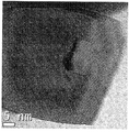
- FIG. 15 is a TEM photograph of cerium oxide particles prepared by the method of Comparative Example 1.
- Cerium oxide production method of the present invention the step of rapidly heating the cerium compound to 700 to 1,000 °C, preferably 750 to 950 °C; Calcining the cerium compound at 700 to 1,000 ° C., preferably 750 to 950 ° C., to produce calcined cerium oxide; And quenching the calcined cerium oxide to 15 to 30 ° C, preferably 18 to 28 ° C, more preferably to room temperature (25 ° C).
- the calcining means a heat treatment process for heating a substance to a high temperature to remove some or all of the volatile fraction of the substance, in the present invention, the cerium
- the compound is formed into cerium oxide (polishing particles) by calcination. For example, calcination removes carbon dioxide (CO 2 ), moisture (H 2 O), and the like from cerium carbonate (Ce 2 (CO 3 ) 3 ⁇ 6H 2 O) to form cerium oxide (2CeO 2 ). .
- the calcination temperature which may vary depending on the type of cerium compound, is about 700 to 1,000 °C, preferably about 750 to 950 °C. Calcining the cerium compound is preferably carried out for 10 minutes to 2 hours, preferably 15 to 90 minutes. If the calcination time is less than 10 minutes, the calcination of the cerium compound may be incomplete, the cerium oxide formation may be incomplete, if more than 2 hours, the strength of the cerium oxide produced is excessively increased, the solid cerium oxide is There is a risk of causing scratches on a polishing substrate such as a wafer, which is uneconomical.
- the calcination temperature is out of the range, the calcination of the cerium compound is incomplete or excessively performed, there is a fear that the produced cerium oxide may not have desirable properties, if the temperature of the quenching step is out of the range, There is a fear that minute cracks may not be completely formed on the surface of cerium oxide particles.
- the cerium compound is 15 to 30 °C, preferably 18 to 28 °C, more preferably at room temperature (25 °C), 20 to 900 °C / min, preferably, 50 to 500 °C It is heated at a heating rate of / min, and in the quenching step, the calcined cerium oxide is preferably cooled at a cooling rate of 20 to 400 °C / minute, preferably 20 to 100 °C / minute. If the heating rate of the rapid heating step is out of the range, cerium oxide may be difficult to form or may not be able to sufficiently form fine cracks on the surface of the cerium oxide particles, and the cooling rate of the quenching step may be out of the range. In this case, there is a fear that minute cracks cannot be sufficiently formed on the surface of the cerium oxide particles.
- the rapid heating, calcining and quenching step is performed at least once, preferably one or more times, more preferably may be repeated 2 to 3 times.
- the surface of the cerium oxide particles becomes more uneven, the density of the cerium oxide particles is further reduced, and the cerium oxide particles can be more easily broken by external impact.
- a conventional cerium compound used for producing cerium oxide can be used, and preferably cerium carbonate, cerium hydroxide, cerium sulfate, and cerium oxalate cerium oxalate and cerium compounds selected from the group consisting of mixtures thereof, more preferably cerium carbonate.
- the cerium oxide produced by the production method of the present invention has a main peak having a 2 ⁇ value of 27 to 30 ° and a minor peak of 30 to 35 ° in an X-ray diffraction graph, and has an area intensity ratio between the main peak and the sub peak ( intensity ratio (area ratio): Main peak / minor peak) is 3.0 or more.
- the average particle (crystal) size of the cerium oxide powder (particle) is 20 to 50 nm, preferably 25 to 45 nm.
- the particle (crystal) size of the cerium oxide powder is determined by the Scherrer Equation using the full width at half maximum (FWHM) of the cerium oxide powder by X-ray diffraction analysis. Can be obtained by substitution.
- the particle size of the cerium oxide powder is less than 20nm, there is a fear that the polishing rate and polishing selectivity in the CMP process is inferior, and if the particle size of the cerium oxide powder exceeds 50nm, fine scratches on the polishing substrate in the CMP process It may occur.
- the slurry composition which concerns on this invention contains the said cerium oxide particle
- the slurry composition of the present invention has a cerium oxide of 0.1 to 10% by weight, preferably 0.5 to 5% by weight based on the total weight of the slurry composition, and 2 to 20 parts by weight of a dispersant, preferably 100% by weight of the cerium oxide particles. 3 to 15 parts by weight and the remaining water (water), preferably deionized water or pure water.
- the cerium oxide particles may not be able to sufficiently function the abrasive particles, and the polishing rate and the polishing selectivity may deteriorate, and the content of the cerium oxide particles may be 10% by weight. If exceeded, there is a fear that delamination of the slurry composition due to entanglement, agglomeration, or precipitation of cerium oxide particles may occur, and fine scratches may be further generated in the CMP process.
- the dispersant used in the present invention is added to uniformly disperse the abrasive particles in the slurry composition, and a conventional dispersant used in a conventional CMP slurry composition can be used, for example, a carboxylic acid or a salt thereof. Dispersant may be used.
- a conventional dispersant used in a conventional CMP slurry composition can be used, for example, a carboxylic acid or a salt thereof.
- Dispersant may be used.
- polycarboxylic acid or its salt More preferably, polyacrylic acid or its salt (ammonium polyacrylate salt etc.) can be used.
- carboxylic acid examples include glutaric acid, glutamic acid, glycolic acid, glycolic acid, lauric acid, lactic acid, malic acid, Malonic acid, valeric acid, citric acid, stearic acid, succinic acid, acetic acid, oxalic acid, adipic acid acid, capric acid, caproic acid, caproic acid, caprylic acid, formic acid, fumaric acid, phthalic acid, propionic acid, Pyruvic acid (tarruric acid), tartaric acid (tartaric acid), polyacrylic acid (polyacrylic acid) and salts thereof, mixtures thereof and the like can be exemplified.
- the salt of the carboxylic acid conventional carboxylic acid salts such as sodium salt, ammonium salt, and potassium salt may be used.
- the dispersant one or more of the above carboxylic acids or salts thereof may be used.
- the weight average molecular weight of the dispersant is 5000 to 20000, preferably 10000 to 15000, and when the weight average molecular weight of the dispersant is less than 5000 or more than 20000, the dispersibility of the slurry composition is sufficient. There is a risk of not doing it.
- the cerium oxide in the slurry composition may not be sufficiently dispersed and may be entangled, aggregated, or precipitated. There is no fear that the dispersant may act as an impurity, and there is no particular advantage.
- the cerium oxide slurry composition can be produced by adding the cerium oxide particles and the dispersant to water (deionized water).
- a dispersing device may be used to prevent agglomeration of the cerium oxide particles in the slurry composition.
- the dispersing apparatus may use a conventional stirrer and a dispersion device, and specific examples thereof include a shaker, a homogenizer, a paint shaker, an ultrasonic homogenizer, A bead mill, a roll mill, an apex mill, a vibration ball mill, the dispersion apparatus which mixed them, etc. can be illustrated.
- a bead mill conventional beads such as zirconia beads, alumina beads and glass beads can be used as the dispersion medium.
- cerium carbonate powder at room temperature (25 ° C.) was placed in a platinum bowl and slowly pushed into a tube-shaped furnace heated to 700 ° C. (calcination temperature). At this time, by adjusting the pushing rate of the platinum container, the heating rate of the cerium carbonate powder was adjusted to 100 °C / min. The cerium carbonate powder was heated to a calcination temperature (700 ° C.), and then calcined for 1 hour. Next, the said platinum container was taken out, it put into the previously prepared desiccator, and it cooled to room temperature (cooling rate 50 degreeC / min), and obtained the yellow powder. The cooling rate was adjusted by adjusting the temperature of the cooling water flowing around the desiccator.
- a yellow powder was prepared in the same manner as in Example 1, except that the calcination temperature was changed to 800 ° C. (Example 2), 900 ° C. (Example 3), and 1000 ° C. (Example 4) instead of 700 ° C. It was.
- X-ray diffraction analysis confirmed that the yellow powder was cerium oxide, and the average particle size of each cerium oxide particle was measured in the same manner as in Example 1, and is shown in Table 1 below.
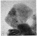
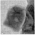
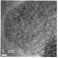
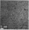
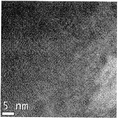
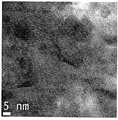
- TEM images of the cerium oxide powders prepared in Examples 2 to 4 are shown in FIGS. 2 to 4.
- Example 8 Change the calcining temperature to 900 ° C. instead of 700 ° C., and change the heating rate to 20 ° C./min instead of 100 ° C./min (Example 5), 50 ° C./min (Example 6) 450 ° C./min (Example 7) and 900
- a yellow powder was prepared in the same manner as in Example 1, except that it was changed to ° C / min (Example 8).
- X-ray diffraction analysis confirmed that the yellow powder was cerium oxide, and the average particle size of each cerium oxide particle was measured in the same manner as in Example 1, and is shown in Table 1 below.
- TEM photographs of the cerium oxide powders prepared in Examples 5 to 8 are shown in FIGS. 5 to 8.
- Example 9 Change the calcination temperature to 900 ° C. instead of 700 ° C., heating rate to 450 ° C./min instead of 100 ° C./min, and cooling rate 20 ° C./min instead of 50 ° C./min (Example 9), 100 ° C./min (implementation A yellow powder was prepared in the same manner as in Example 1, except that Example 10) and 200 ° C / min (Example 11) were changed. X-ray diffraction analysis confirmed that the yellow powder was cerium oxide, and the average particle size of each cerium oxide particle was measured in the same manner as in Example 1, and is shown in Table 1 below. TEM images of the cerium oxide powders prepared in Examples 9 to 11 are shown in FIGS. 9 to 11.
- Example 12 Change the calcination temperature to 900 ° C instead of 700 ° C, the heating rate to 450 ° C / minute instead of 100 ° C / minute, change the calcination time to 30 minutes instead of 1 hour, and repeat the heating, calcination and cooling steps one more time. Except that, a yellow powder was prepared in the same manner as in Example 1. X-ray diffraction analysis confirmed that the yellow powder was cerium oxide, and the average particle size of the cerium oxide particles was measured in the same manner as in Example 1, and is shown in Table 1 below. A TEM image of the cerium oxide powder prepared in Example 12 is shown in FIG. 12.
- a yellow powder was prepared in the same manner as in Example 12, except that the calcination time was changed to 20 minutes instead of 30 minutes, and the heating, calcination and cooling steps were further repeated twice.
- X-ray diffraction analysis confirmed that the yellow powder was cerium oxide, and the average particle size of the cerium oxide particles was measured in the same manner as in Example 1, and is shown in Table 1 below.
- a TEM photograph of the cerium oxide powder prepared in Example 13 is shown in FIG. 13.
- a yellow powder was prepared in the same manner as in Example 12, except that the calcination time was changed to 15 minutes instead of 30 minutes, and the heating, calcination and cooling steps were further repeated three times.
- X-ray diffraction analysis confirmed that the yellow powder was cerium oxide, and the average particle size of the cerium oxide particles was measured in the same manner as in Example 1, and is shown in Table 1 below.
- a TEM photograph of the cerium oxide powder prepared in Example 14 is shown in FIG. 14.
- Example 1 100 700 60 50 28
- Example 2 800 30
- Example 3 900 36
- Example 4 1000
- Example 5 20
- Example 6 50
- Example 7 450
- Example 8 900 29
- Example 9 450
- Example 10 100 38
- Example 11 200
- Example 12 30
- Example 13 20 2 repetitions 34
- Example 14 15 3 repetitions 33 Comparative Example 1 10 60 10 44
- Blanket silicon having a silicon oxide layer (thickness: 1.0 ⁇ m), using the respective slurry compositions prepared in Examples 15 to 28 and Comparative Example 2 and the IPEC AVANTI 472 polishing apparatus from Entrepix, Inc. (United States).
- a blanket silicon wafer (8 inches in diameter) having a wafer (8 inches in diameter) and a silicon nitride layer was polished.
- the silicon oxide film was manufactured by TEOS (Tetra Ethyl Ortho Silicate) -plasma (CVD) chemical vapor deposition (CVD) method, and the silicon nitride film was produced by low pressure CVD method.
- the polishing was performed for 1 minute at a slurry flow rate of 150 cc / min at a downward head pressure of 4 psi, a table speed of 60 rpm, and a head speed of 50 rpm.
- the wafer was washed with deionized water (pure water) and dried, and then the thickness of the silicon oxide film and silicon nitride film remaining on the wafer was measured by an optical interferometer to measure the polishing rate of the oxide and nitride films of Table 2 below. It was. In addition, it is shown in Table 2 by measuring the number of fine scratches of 0.3 ⁇ 2.5 ⁇ m size.
- the slurry composition containing the cerium oxide particles (Examples 1 to 14) of the present invention is relatively fast compared to the slurry composition containing the cerium oxide particles (Comparative Example 1) and has a relatively high oxide film removal rate. Since it has a slow removal rate of nitride film, it turns out that the polishing selectivity of a computed film and a nitride film is excellent.
- the cerium oxide particles of the present invention are not uniformly arranged in various directions in the lattice pattern and appear faintly.
- This non-uniform lattice pattern is formed by minute cracks on the surface of the cerium oxide particles produced by the control of the heating rate and cooling rate.
- the cerium oxide abrasive particles of the present invention can be easily broken by external pressure during the polishing process, thereby reducing the fine scratch formation on the surface to be polished, and the broken abrasive particles are further polished. Therefore, the cerium oxide abrasive particles of the present invention have high polishing rate and polishing selectivity, and are particularly suitable for the Shallow Trench Isolation (STI) CMP process.
- STI Shallow Trench Isolation
- Example 21 Example 7
- Examples 26 to 28 Examples 12 to 14
- the polishing rate of the slurry composition with respect to the oxide film was increased, and It can be seen that the polishing rate and the number of fine scratches are reduced.
- 7 and 12 to 14 it can be seen that the lattice pattern of the abrasive grains of FIGS. 12 to 14 is more non-uniform than the lattice pattern of the abrasive grains of FIG. 7. This difference is due to the increase in fine cracks formed in the abrasive particles through repeated heating and quenching during the production of cerium oxide abrasive particles.
Landscapes
- Chemical & Material Sciences (AREA)
- Organic Chemistry (AREA)
- Engineering & Computer Science (AREA)
- Materials Engineering (AREA)
- Life Sciences & Earth Sciences (AREA)
- Geology (AREA)
- Inorganic Chemistry (AREA)
- Analytical Chemistry (AREA)
- Compounds Of Alkaline-Earth Elements, Aluminum Or Rare-Earth Metals (AREA)
- Finish Polishing, Edge Sharpening, And Grinding By Specific Grinding Devices (AREA)
- Mechanical Treatment Of Semiconductor (AREA)
Abstract
산화세륨(cerium oxide, ceria) 파우더의 제조방법 및 이를 포함하는 슬러리 조성물이 개시된다. 상기 슬러리 조성물은, 화학기계적 연마 공정에서, 높은 연마 속도 및 높은 연마 선택성을 가지며, 미세 스크래치(micro scratches)를 감소시킬 수 있다. 상기 산화세륨 파우더의 제조방법은, 세륨 화합물을 700 내지 1,000℃까지 급가열시키는 단계; 하소된 산화세륨(calcined cerium oxide)을 생성시키기 위하여, 상기 세륨 화합물을 700 내지 1,000℃에서 하소(calcining)하는 단계; 및 하소된 산화세륨을 15 내지 30℃까지 급냉각시키는 단계를 포함한다. 여기서, 상기 세륨 화합물을 하소하는 단계는 10분 내지 2시간 동안 수행되는 것이고, 상기 급가열 단계에서, 상기 세륨 화합물은 20 내지 900℃/분의 가열 속도로 가열되는 것이며, 상기 급냉각 단계에서, 상기 하소된 산화세륨은 20 내지 400℃/분의 냉각 속도로 냉각되는 것이 바람직하다.
Description
본 발명은 산화세륨(cerium oxide, ceria) 파우더의 제조방법 및 이를 포함하는 슬러리 조성물에 관한 것이다. 본 발명의 슬러리 조성물은, 화학기계적 연마 공정에서, 높은 연마 속도 및 높은 연마 선택성을 가지며, 미세 스크래치(micro scratches)를 감소시킬 수 있다.
반도체 소자의 집적도가 증가함에 따라, 반도체 소자 제조를 위한 고정밀도의 노광 공정에서 마진을 확보하기 위하여 광역평탄화 공정이 도입되었다. 화학기계적 연마(Chemical Mechanical Polishing: CMP) 공정은 이러한 반도체 소자의 광역평탄화에 일반적으로 이용되고 있으며, 다른 평탄화 방법과 비교하여, CMP 공정의 평탄화 능력이 우수하고, 공정이 상대적으로 간단한 장점이 있다.
화학기계적 연마 공정에 사용되는 연마 슬러리 조성물은 일반적으로 연마 입자, 탈이온수 및 다양한 첨가제를 포함하고 있다. 상기 연마 입자의 대표적인 예로는 콜로이달 실리카 입자, 퓸드 실리카 입자 등이 있다. 그러나, 이러한 통상의 연마 입자는 산화막의 연마 속도가 낮고, 산화막과 질화막의 연마 선택성이 낮아, 원하는 연마 결과를 얻기 위해서는, 여러 단계의 공정이 추가로 진행되어야 하는 점에서, 충분히 만족스럽지 못하다.
상기 문제점을 보완하기 위하여, 산화세륨 입자를 사용하는 슬러리 조성물이 연구되고 있다. 상기 산화세륨 입자는 유리 제품의 가공에 일반적으로 사용되고 있다. 또한, 산화세륨 입자를 포함하는 슬러리 조성물은 산화막의 연마 속도 및 산화막과 질화막의 연마 선택성을 증가시키는 것으로 알려져 있다. 그러나, 산화세륨 입자의 비중은 실리카 입자에 비하여 6 내지 8배 높으며, 이는 슬러리 조성물의 분산 안정성을 저해한다. 더욱이, 산화세륨 입자들은 CMP 공정 중 응집되기 쉬우므로, 연마 기판에 바람직하지 못한 미세 스크래치를 발생시킵니다. 특히, STI(Shallow Trench Isolation) CMP 공정은 트렌치의 깊이가 얇기 때문에, STI CMP 공정에서 생성된 미세 스크래치는 반도체 소자의 품질이나 생산성에 심각한 저하를 가져올 수 있다. 미세 스크래치의 생성은 연마 입자의 모양과 크기에 기인하는 것으로 알려져 있다.
한국특허공개 10-2007-0087037호(국제공개 No. WO 2000/39843의 국내단계)에는 산화세륨 입자의 제조방법 및 이를 포함하는 CMP 슬러리 조성물에 대하여 개시되어 있다. 상기 특허에는 STI CMP 슬러리 조성물용 연마 입자의 바람직한 특성과 바람직한 첨가제들이 개시되어 있다. 한편, 한국특허공개 10-2007-0087840호는 슬러리 조성물을 숙성시켜 미세 스크래치를 감소시킨다. 한국특허공개 10-2002-0009619호(국제공개 No. WO 2000/73211의 국내단계)에는 가열 속도에 따른 산화세륨 입자의 제조방법에 대하여 개시되어 있다. 그러나, 상기 산화세륨 입자 제조방법들은 산화세륨 입자에 의한 미세 스크래치 감소에 있어서, 충분히 만족스럽지 못하다.
따라서, 본 발명의 목적은, CMP 공정에서, 높은 연마 속도 및 연마 선택성을 가지며, 미세 스크래치를 감소시킬 수 있는, 산화세륨 파우더의 제조방법 및 이를 포함하는 슬러리 조성물을 제공하는 것이다. 본 발명의 다른 목적은, STI(Shallow Trench Isolation) CMP 공정에 적합한 산화세륨 파우더의 제조방법 및 이를 포함하는 슬러리 조성물을 제공하는 것이다.
상기 목적을 달성하기 위하여, 본 발명은, 세륨 화합물을 700 내지 1,000℃까지 급가열시키는 단계; 하소된 산화세륨(calcined cerium oxide)을 생성시키기 위하여, 상기 세륨 화합물을 700 내지 1,000℃에서 하소(calcining)하는 단계; 및 하소된 산화세륨을 15 내지 30℃까지 급냉각시키는 단계를 포함하는 산화세륨 파우더의 제조방법을 제공한다. 여기서, 상기 세륨 화합물을 하소하는 단계는 10분 내지 2시간 동안 수행되는 것이고, 상기 급가열 단계에서, 상기 세륨 화합물은 20 내지 900℃/분의 가열 속도로 가열되는 것이며, 상기 급냉각 단계에서, 상기 하소된 산화세륨은 20 내지 400℃/분의 냉각 속도로 냉각되는 것이 바람직하다.
또한, 본 발명은 슬러리 조성물 전체 중량에 대하여, 상기 산화세륨 입자 0.1 내지 10중량%; 상기 산화세륨 입자 100중량부에 대하여, 분산제 2 내지 20중량부; 및 나머지 물(water)를 포함하는, 산화세륨을 포함하는 슬러리 조성물을 제공한다.
본 발명에 따른 산화세륨(cerium oxide, ceria) 파우더 제조방법은, 세륨 화합물을 하소하는 과정에서, 급가열 및 급냉각 단계를 통해 산화세륨 입자(연마 입자) 표면에 미세한 균열을 형성하는 것으로서, 제조된 연마 입자는 표면이 불균일하고 입자의 치밀도가 낮아, 외부 충격에 쉽게 부서질 수 있는 성질을 가지게 된다. 따라서, 본 발명의 연마 입자는, 웨이퍼 연마 공정 중에, 외부 압력에 의하여 쉽게 부서짐으로써 피연마면의 미세 스크래치를 현저히 감소시킬 수 있고, 부서진 연마 입자들이 또다시 웨이퍼의 연마를 진행하기 때문에, 높은 연마 속도 및 연마 선택성을 가지게 되므로, 민감한 STI(Shallow Trench Isolation) 화학기계적 연마(CMP) 공정에 유용하다.
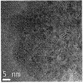
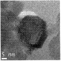
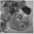
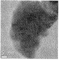
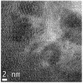
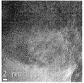
도 1 내지 14는, 각각 본 발명의 실시예 1 내지 14의 방법으로 제조된 산화세륨 입자의 TEM 사진.
도 15는, 비교예 1의 방법으로 제조된 산화세륨 입자의 TEM 사진.
이하, 본 발명을 상세히 설명하면 다음과 같다.
본 발명의 산화세륨 제조 방법은, 세륨 화합물을 700 내지 1,000℃, 바람직하게는 750 내지 950℃까지 급가열시키는 단계; 상기 세륨 화합물을 700 내지 1,000℃, 바람직하게는 750 내지 950℃에서 하소(calcining)하여, 하소된 산화세륨(calcined cerium oxide)을 생성시키는 단계; 및 하소된 산화세륨을 15 내지 30℃, 바람직하게는 18 내지 28℃, 더욱 바람직하게는 상온(25℃)까지 급냉각시키는 단계를 포함한다. 상기 하소(calcine or calcination)는, 어떤 물질을 고온으로 가열하여, 그 물질의 휘발성분(volatile fraction) 일부 또는 전부를 제거하는 열처리 공정(thermal treatment process)을 의미하는 것으로서, 본 발명에서, 상기 세륨 화합물은 하소에 의해 산화세륨(연마 입자)으로 형성된다. 예를 들어, 하소에 의하여, 탄산세륨(Ce2(CO3)3·6H2O)에서 이산화탄소(CO2), 수분(H2O) 등이 제거되어 산화세륨(2CeO2)이 형성되는 것이다.
본 발명에 있어서, 상기 하소 온도는, 세륨 화합물 종류에 따라 달라질 수 있으며, 약 700 내지 1,000℃, 바람직하게는 약 750 내지 950℃이다. 상기 세륨 화합물을 하소하는 단계는 10분 내지 2시간, 바람직하게는 15 내지 90분 동안 수행되는 것이 바람직하다. 상기 하소 시간이 10분 미만이면, 세륨 화합물의 하소가 불완전하여 산화세륨 형성이 완전하지 못할 우려가 있고, 2시간을 초과하면, 생성되는 산화세륨의 강도를 과도하게 증가시키고, 상기 단단한 산화세륨이 웨이퍼 등의 연마 기판에 스크래치를 유발할 우려가 있으며, 비경제적이다. 상기 하소 온도가 상기 범위를 벗어날 경우, 세륨 화합물의 하소가 불완전하거나 과도하게 수행되고, 생성된 산화세륨이 바람직한 성질을 갖지 못할 우려가 있고, 상기 급냉각 단계의 온도가 상기 범위를 벗어날 경우, 생성되는 산화세륨 입자의 표면에 미세한 균열을 완전히 형성시키지 못할 우려가 있다.
상기 급가열 단계에서, 상기 세륨 화합물은, 15 내지 30℃, 바람직하게는 18 내지 28℃, 더욱 바람직하게는 상온(25℃)에서, 20 내지 900℃/분, 바람직하게는, 50 내지 500℃/분의 가열 속도로 가열되는 것이며, 상기 급냉각 단계에서, 상기 하소된 산화세륨은 20 내지 400℃/분, 바람직하게는, 20 내지 100℃/분의 냉각 속도로 냉각되는 것이 바람직하다. 상기 급가열 단계의 가열 속도가 상기 범위를 벗어날 경우, 산화세륨 형성이 어려워지거나, 산화세륨 입자의 표면에 미세한 균열을 충분히 형성시키지 못할 우려가 있고, 상기 급냉각 단계의 냉각 속도가 상기 범위를 벗어날 경우, 산화세륨 입자의 표면에 미세한 균열을 충분히 형성시키지 못할 우려가 있다.
본 발명에 있어서, 상기 급가열, 하소 및 급냉각 단계는 적어도 1회 수행되는 것으로서, 바람직하게는 1회 이상, 더욱 바람직하게는 2 내지 3회 반복할 수 있다. 상기 급가열, 하소 및 급냉각 단계를 반복 수행함으로써, 산화세륨 입자의 표면은 더욱 불균일해지고, 산화세륨 입자의 치밀도는 더욱 감소되며, 산화세륨 입자는 외부 충격에 의해 더욱 쉽게 부서질 수 있게 된다. 본 발명에 사용되는 세륨 화합물로는, 산화세륨 제조에 쓰이는 통상적인 세륨 화합물을 사용할 수 있으며, 바람직하게는 탄산세륨(cerium carbonate), 수산화세륨(cerium hydroxide), 황산세륨(cerium sulfate), 옥살산세륨(cerium oxalate) 및 이들의 혼합물로 이루어진 군으로부터 선택되는 세륨 화합물, 더욱 바람직하게는 탄산세륨을 사용할 수 있다.
본 발명의 제조방법에 의해 제조된 산화세륨은, X선 회절그래프에서, 2θ 값이 27 내지 30°인 주 피크와 30 내지 35°인 부 피크를 가지며, 주 피크와 부 피크의 면적강도비(intensity ratio(area ratio): 주 피크/부 피크)가 3.0 이상인 것이다. 상기 산화세륨 분말(입자)의 평균 입자(결정) 크기는 20 내지 50nm, 바람직하게는 25 내지 45nm이다. 상기 산화세륨 분말의 입자(결정) 크기는 산화세륨 분말의 X선 회절법(X-ray diffraction analysis)에 의한 주 피크의 반값 폭(full width at half maximum, FWHM)을 셰러 방정식(Scherrer Equation)에 대입하여 얻을 수 있다. 상기 산화세륨 분말의 입자 크기가 20nm 미만인 경우, CMP 공정에서의 연마 속도 및 연마 선택성이 떨어질 우려가 있고, 상기 산화세륨 분말의 입자 크기가 50nm를 초과할 경우, CMP 공정에서 연마 기판에 미세 스크래치가 발생할 우려가 있다.
본 발명에 따른 슬러리 조성물은, 상기 산화세륨 입자를 포함하는 것으로서, 미세 스크래치에 의해 반도체 소자의 성능이나 생산성이 크게 떨어지는 STI CMP 공정에 특히 적합한 것이다. 본 발명의 슬러리 조성물은, 슬러리 조성물 전체 중량에 대하여, 산화세륨 0.1 내지 10중량%, 바람직하게는 0.5 내지 5중량%, 상기 산화세륨 입자 100중량부에 대하여, 분산제 2 내지 20중량부, 바람직하게는 3 내지 15중량부 및 나머지 물(water), 바람직하게는 탈이온수 또는 순수를 포함한다. 상기 산화세륨 입자의 함량이 0.1중량% 미만이면, 산화세륨 입자가 연마 입자의 기능을 충분히 할 수 없어, 연마 속도 및 연마 선택성 등이 떨어질 우려가 있으며, 상기 산화세륨 입자의 함량이 10중량%를 초과하면, 산화세륨 입자의 엉김, 응집 또는 침전으로 인한 슬러리 조성물의 층분리가 발생할 우려가 있고, CMP 공정에서 미세 스크래치가 더욱 발생될 우려가 있다.
본 발명에 사용되는 분산제는, 슬러리 조성물에서 연마 입자를 균일하게 분산시키기 위하여 첨가하는 것으로서, 통상의 CMP 슬러리 조성물에 사용되는 통상의 분산제를 사용할 수 있으며, 예를 들어, 카르복실산 또는 그 염 등의 분산제를 사용할 수 있다. 바람직하게는 폴리카르복실산 또는 그 염, 더욱 바람직하게는 폴리아크릴산(polyacrylic acid) 또는 그 염(폴리아크릴산 암모늄염 등)을 사용할 수 있다. 상기 카르복실산의 구체적인 예로는 글루타르산(glutaric acid), 글루콘산(gluconic acid), 글리콜산(glycolic acid), 라우르산(lauric acid), 락트산(lactic acid), 말산(malic acid), 말론산(malonic acid), 발레르산(valeric acid), 시트르산(citric acid), 스테아르산(stearic acid), 숙신산(succinic acid), 아세트산(acetic acid), 옥살산(oxalic acid), 아디프산(adipic acid), 카프르산(capric acid), 카프로산(caproic acid), 카프릴산(caprylic acid), 포름산(formic acid), 푸마르산(fumaric acid), 프탈산(phthalic acid), 프로피온산(propionic acid), 피루브산(pyruvic acid), 타르타르산(tartaric acid), 폴리아크릴산(polyacrylic acid) 및 이들의 염, 이들의 혼합물 등을 예시할 수 있다. 그리고 상기 카르복실산의 염으로는 나트륨염, 암모늄염, 포타시움염 등 통상적인 카르복실산 염들을 사용할 수 있다. 분산제로서, 상기 카르복실산 또는 그 염이 하나 이상 사용될 수 있다. 상기 분산제가 폴리카르복실산일 경우, 상기 분산제의 중량 평균 분자량은 5000 내지 20000, 바람직하게는 10000 내지 15000이며, 상기 분산제의 중량 평균 분자량이 5000 미만이거나 20000을 초과하면, 슬러리 조성물의 분산성이 충분하지 못할 우려가 있다. 상기 분산제의 함량이 상기 산화세륨 입자 100중량부에 대하여, 2중량부 미만이면, 슬러리 조성물 내의 산화세륨이 충분히 분산이 안 되어, 엉김, 응집 또는 침전될 우려가 있고, 20중량부를 초과하면, 과량의 분산제가 불순물로서 작용할 우려가 있을 뿐, 특별한 장점은 없다.
상기 산화세륨 슬러리 조성물은, 상기 산화세륨 입자 및 분산제를 물(탈이온수)에 첨가함으로써 제조할 수 있다. 산화세륨 입자를 물에 분산시킬 때, 슬러리 조성물에서 산화세륨 입자가 응집되는 것을 방지하기 위하여, 분산 장치를 사용할 수 있다. 상기 분산 장치는 통상의 교반기(stirrer) 및 분산기(dispersion device)를 사용할 수 있으며, 구체적인 예로는 쉐이커(shaker), 호모지나이저(homogenizer), 페인트 쉐이커(paint shaker), 초음파 분산기(ultrasonic homogenizer), 비드밀(bead mill), 롤밀(roll mill), 아펙스밀(apex mill), 진동볼밀(vibration ball mill) 및 이들을 혼용한 분산장치 등을 예시할 수 있다. 비드밀을 사용하는 경우, 분산 매체로서, 지르코니아 비드, 알루미나 비드 및 유리 비드 등 통상의 비드를 사용할 수 있다.
이하, 구체적인 실시예를 통하여 본 발명을 더욱 상세히 설명한다. 하기 실시예는 본 발명을 예시하기 위한 것으로서, 본 발명이 하기 실시예에 의해 한정되는 것은 아니다.
[실시예 1] 산화세륨의 제조
실온(25℃)의 탄산세륨 분말 30g을 백금용기(platinum bowl)에 담아, 서서히 700℃(하소 온도)로 가열된 튜브로(tube-shaped furnace)에 밀어 넣었다. 이때 상기 백금용기를 밀어 넣는 속도를 조절하여, 탄산세륨 분말의 가열 속도를 100℃/분으로 조절하였다. 상기 탄산세륨 분말을 하소 온도(700℃)까지 승온시킨 후, 1시간 동안 하소시켰다. 다음으로, 상기 백금용기를 꺼내어 미리 준비한 데시케이터에 넣고, 실온으로 냉각(냉각 속도 50℃/분)시켜 노란색의 분말을 얻었다. 상기 냉각 속도는 데시케이터 주변에 흐르는 냉각수의 온도를 조절함으로써 조정하였다. X선 회절법으로 분석하여, 상기 노란색 분말이 산화세륨인 것을 확인하였고, 상기 산화세륨 분말을 X선 회절법에 의한 주 피크의 반값 폭(full width at half maximum, FWHM)을 셰러 방정식(Scherrer Equation)에 대입한 결과, 평균 입자 크기가 약 28nm인 것을 확인할 수 있었다(표 1). 실시예 1에서 제조된 산화세륨 분말의 TEM(transmission electron microscopy) 사진을 도 1에 나타내었다.
[실시예 2 내지 4] 산화세륨의 제조
하소 온도를 700℃ 대신 800℃(실시예 2), 900℃(실시예 3) 및 1000℃(실시예 4)로 변경한 것을 제외하고는, 상기 실시예 1과 동일한 방법으로 노란색의 분말을 제조하였다. X선 회절법으로 분석하여, 상기 노란색 분말이 산화세륨인 것을 확인하였고, 상기 실시예 1과 동일한 방법으로 각각의 산화세륨 입자의 평균 입자 크기를 측정하여 하기 표 1에 나타내었다. 실시예 2 내지 4에서 제조된 산화세륨 분말의 TEM 사진을 도 2 내지 4에 나타내었다.
[실시예 5 내지 8] 산화세륨의 제조
하소 온도를 700℃ 대신 900℃로 변경하고, 가열 속도를 100℃/분 대신 20℃/분(실시예 5), 50℃/분(실시예 6) 450℃/분(실시예 7) 및 900℃/분(실시예 8)으로 변경한 것을 제외하고는, 상기 실시예 1과 동일한 방법으로 노란색의 분말을 제조하였다. X선 회절법으로 분석하여, 상기 노란색 분말이 산화세륨인 것을 확인하였고, 상기 실시예 1과 동일한 방법으로 각각의 산화세륨 입자의 평균 입자 크기를 측정하여 하기 표 1에 나타내었다. 실시예 5 내지 8에서 제조된 산화세륨 분말의 TEM 사진을 도 5 내지 8에 나타내었다.
[실시예 9 내지 11] 산화세륨의 제조
하소 온도를 700℃ 대신 900℃로, 가열 속도를 100℃/분 대신 450℃/분으로 변경하고, 냉각 속도를 50℃/분 대신 20℃/분(실시예 9), 100℃/분(실시예 10) 및 200℃/분(실시예 11)으로 변경한 것을 제외하고는, 상기 실시예 1과 동일한 방법으로 노란색의 분말을 제조하였다. X선 회절법으로 분석하여, 상기 노란색 분말이 산화세륨인 것을 확인하였고, 상기 실시예 1과 동일한 방법으로 각각의 산화세륨 입자의 평균 입자 크기를 측정하여 하기 표 1에 나타내었다. 실시예 9 내지 11에서 제조된 산화세륨 분말의 TEM 사진을 도 9 내지 11에 나타내었다.
[실시예 12] 산화세륨의 제조
하소 온도를 700℃ 대신 900℃로, 가열 속도를 100℃/분 대신 450℃/분으로 변경하고, 하소 시간을 1시간 대신 30분으로 변경하고 가열, 하소 및 냉각 단계를 1회 더욱 반복한 것을 제외하고는, 상기 실시예 1과 동일한 방법으로 노란색의 분말을 제조하였다. X선 회절법으로 분석하여, 상기 노란색 분말이 산화세륨인 것을 확인하였고, 상기 실시예 1과 동일한 방법으로 산화세륨 입자의 평균 입자 크기를 측정하여 하기 표 1에 나타내었다. 실시예 12에서 제조된 산화세륨 분말의 TEM 사진을 도 12에 나타내었다.
[실시예 13] 산화세륨의 제조
하소 시간을 30분 대신 20분으로 변경하고 가열, 하소 및 냉각 단계를 2회 더욱 반복한 것을 제외하고는, 상기 실시예 12와 동일한 방법으로 노란색의 분말을 제조하였다. X선 회절법으로 분석하여, 상기 노란색 분말이 산화세륨인 것을 확인하였고, 상기 실시예 1과 동일한 방법으로 산화세륨 입자의 평균 입자 크기를 측정하여 하기 표 1에 나타내었다. 실시예 13에서 제조된 산화세륨 분말의 TEM 사진을 도 13에 나타내었다.
[실시예 14] 산화세륨의 제조
하소 시간을 30분 대신 15분으로 변경하고 가열, 하소 및 냉각 단계를 3회 더욱 반복한 것을 제외하고는, 상기 실시예 12와 동일한 방법으로 노란색의 분말을 제조하였다. X선 회절법으로 분석하여, 상기 노란색 분말이 산화세륨인 것을 확인하였고, 상기 실시예 1과 동일한 방법으로 산화세륨 입자의 평균 입자 크기를 측정하여 하기 표 1에 나타내었다. 실시예 14에서 제조된 산화세륨 분말의 TEM 사진을 도 14에 나타내었다.
[비교예 1] 산화세륨의 제조
실온(25℃)의 탄산세륨 분말 30g을 백금용기(platinum bowl)에 담아, 서서히 900℃(하소 온도)로 가열된 튜브로(tube-shaped furnace)에 밀어 넣었다. 이때 상기 백금용기를 밀어 넣는 속도를 조절하여, 탄산세륨 분말의 가열 속도를 10℃/분으로 조절하였다. 상기 탄산세륨 분말을 하소 온도(900℃)까지 승온시킨 후, 900℃에서 1시간 동안 하소시켰다. 다음으로, 하소된 산화세륨을 튜브로 내에서 실온으로 냉각(냉각 속도 10℃/분)시켜 노란색의 분말을 얻었다. X선 회절법으로 분석하여, 상기 노란색 분말이 산화세륨인 것을 확인하였고, 상기 실시예 1과 동일한 방법으로 산화세륨 입자의 평균 입자 크기를 측정하여 하기 표 1에 나타내었다. 비교예 1에서 제조된 산화세륨 분말의 TEM 사진을 도 15에 나타내었다.
표 1
| 산화세륨 제조 조건 | ||||||
| 가열 속도(℃/분) | 하소 온도(℃) | 하소 시간(분) | 냉각 속도(℃/분) | 추가적인가열/냉각 | 평균 입자 크기 (nm) | |
| 실시예 1 | 100 | 700 | 60 | 50 | 28 | |
| 실시예 2 | 800 | 30 | ||||
| 실시예 3 | 900 | 36 | ||||
| 실시예 4 | 1000 | 42 | ||||
| 실시예 5 | 20 | 900 | 36 | |||
| 실시예 6 | 50 | 35 | ||||
| 실시예 7 | 450 | 31 | ||||
| 실시예 8 | 900 | 29 | ||||
| 실시예 9 | 450 | 20 | 31 | |||
| 실시예 10 | 100 | 38 | ||||
| 실시예 11 | 200 | 39 | ||||
| 실시예 12 | 30 | 50 | 1회 반복 | 35 | ||
| 실시예 13 | 20 | 2회 반복 | 34 | |||
| 실시예 14 | 15 | 3회 반복 | 33 | |||
| 비교예 1 | 10 | 60 | 10 | 44 | ||
[실시예 15 내지 28 및 비교예 2] 산화세륨 슬러리 조성물의 제조 및 평가
탈이온수(순수) 1.5kg과 폴리아크릴산 암모늄염용액 1.05g을 프리믹싱 용기에 서서히 투입하여 혼합시킨 후, 각각 상기 실시예 1 내지 14 및 비교예 1에서 제조한 산화세륨 분말 15g을 첨가하고, 상기 혼합물을 지르코니아 비드를 사용하여 비드 밀로 30분 동안 분산시켜, 산화세륨 슬러리 조성물(실시예 15 내지 28 및 비교예 2)을 얻었다.
슬러리 조성물의 평가
실시예 15 내지 28 및 비교예 2에서 제조된 각각의 슬러리 조성물 및 Entrepix, Inc.(미국)의 IPEC AVANTI 472 연마 장치를 사용하여, 실리콘 산화막(silicon oxide layer, 두께: 1.0μm)을 갖는 블랭킷 실리콘 웨이퍼(직경: 8인치(inch)) 및 질화규소막(silicon nitride layer)을 갖는 블랭킷 실리콘 웨이퍼(직경: 8인치(inch))를 연마하였다. 상기 실리콘 산화막은 TEOS(Tetra Ethyl Ortho Silicate)-플라즈마(plasma) CVD(chemical vapor deposition)법으로 제작하였고, 상기 질화규소막은 저압 CVD법으로 제작하였다. 상기 연마는 4psi의 하강압력(downward head pressure), 테이블 속도 60rpm, 헤드(Head) 속도 50rpm에서, 150cc/min의 슬러리 유속으로 1분간 수행되었다. 연마 후, 웨이퍼를 탈이온수(순수)로 세척하고 건조한 다음, 하기 표 2의 산화막 및 질화막의 연마 속도를 측정하기 위하여, 웨이퍼에 잔존하는 실리콘 산화막 및 질화규소막의 두께를 광학 간섭계(optical interferometer)로 측정하였다. 또한, 0.3~2.5μm 크기의 미세 스크래치의 개수를 측정하여 표 2에 나타내었다.
표 2
| 평가 결과 | |||
| 산화막 연마 속도(Å/분) | 질화막 연마 속도(Å/분) | 미세 스크래치 개수 | |
| 실시예 15 | 2845 | 57 | 54 |
| 실시예 16 | 3194 | 72 | 61 |
| 실시예 17 | 3318 | 81 | 63 |
| 실시예 18 | 3452 | 102 | 72 |
| 실시예 19 | 3128 | 74 | 65 |
| 실시예 20 | 3217 | 65 | 67 |
| 실시예 21 | 3026 | 57 | 48 |
| 실시예 22 | 2766 | 51 | 71 |
| 실시예 23 | 3157 | 81 | 66 |
| 실시예 24 | 3311 | 48 | 52 |
| 실시예 25 | 2631 | 50 | 75 |
| 실시예 26 | 3411 | 55 | 45 |
| 실시예 27 | 3215 | 53 | 37 |
| 실시예28 | 3029 | 49 | 36 |
| 비교예 2 | 2455 | 107 | 176 |
상기 표 2로부터, 본 발명의 산화세륨 입자(실시예 1 내지 14)를 포함하는 슬러리 조성물은, 통상의 산화세륨 입자(비교예 1)를 포함하는 슬러리 조성물에 비하여, 빠른 산화막 제거 속도와 상대적으로 느린 질화막 제거 속도를 가지므로, 연산화막과 질화막의 연마 선택성이 우수함을 알 수 있다. 또한, 하기 도 1 내지 14로부터, 본 발명의 산화세륨 입자는 격자무늬(lattice pattern)가 여러 방향으로 일정하지 않게 배열되고, 희미하게 나타나는 것을 알 수 있다. 이러한 불균일한 격자무늬는, 가열 속도와 냉각 속도의 조절에 의하여 생성되는 산화세륨 입자 표면의 미세한 균열에 의해 형성되는 것이다. 본 발명의 산화세륨 연마 입자는 연마 공정 중에 외부 압력에 의하여 쉽게 부서짐으로써, 피연마면의 미세 스크래치 형성을 감소시킬 수 있고, 부서진 연마 입자들은 또다시 연마를 진행한다. 따라서, 본 발명의 산화세륨 연마 입자는 높은 연마 속도 및 연마 선택성을 가지게 되고, STI(Shallow Trench Isolation) CMP 공정에 특히 적합하다.
실시예 21(실시예 7) 및 실시예 26 내지 28(실시예 12 내지 14)로부터, 가열 및 냉각 과정을 1회 이상 더욱 수행하면, 산화막에 대한 슬러리 조성물의 연마 속도가 상승하고, 질화막에 대한 연마 속도 및 미세 스크래치 개수는 감소함을 알 수 있다. 도 7 및 도 12 내지 14를 비교하면, 도 12 내지 14의 연마 입자의 격자무늬가 도 7의 연마 입자의 격자무늬 보다 더욱 불균일하게 형성되었음을 알 수 있다. 이러한 차이는 산화세륨 연마입자 제조 시, 급가열 및 급냉각 단계의 반복을 통하여 연마 입자에 형성되는 미세한 균열이 증가하였기 때문이다.
Claims (5)
- 세륨 화합물을 700 내지 1,000℃까지 급가열시키는 단계;하소된 산화세륨(calcined cerium oxide)을 생성시키기 위하여, 상기 세륨 화합물을 700 내지 1,000℃에서 하소(calcining)하는 단계; 및하소된 산화세륨을 15 내지 30℃까지 급냉각시키는 단계를 포함하는 산화세륨 파우더의 제조방법.
- 제1항에 있어서, 상기 세륨 화합물을 하소하는 단계는 10분 내지 2시간 동안 수행되는 것이고, 상기 급가열 단계에서, 상기 세륨 화합물은 20 내지 900℃/분의 가열 속도로 가열되는 것이며, 상기 급냉각 단계에서, 상기 하소된 산화세륨은 20 내지 400℃/분의 냉각 속도로 냉각되는 것인 산화세륨 파우더의 제조방법.
- 제1항에 있어서, 상기 산화세륨 제조 방법은, 상기 급가열, 하소 및 급냉각 단계가 1회 이상 반복되는 것인 산화세륨 파우더의 제조방법.
- 제1항에 있어서, 상기 세륨 화합물은 탄산세륨, 수산화세륨, 황산세륨, 옥살산세륨 및 이들의 혼합물로 이루어진 군으로부터 선택되는 것인 산화세륨 파우더의 제조방법.
- 슬러리 조성물 전체 중량에 대하여, 산화세륨 입자 0.1 내지 10중량%;상기 산화세륨 입자 100중량부에 대하여, 분산제 2 내지 20중량부; 및나머지 물(water)을 포함하며,상기 산화세륨은, 세륨 화합물을 700 내지 1,000℃까지 급가열시키는 단계; 하소된 산화세륨(calcined cerium oxide)을 생성시키기 위하여, 상기 세륨 화합물을 700 내지 1,000℃에서 하소(calcining)하는 단계; 및 하소된 산화세륨을 15 내지 30℃까지 급냉각시키는 단계를 포함하는 산화세륨 파우더의 제조방법으로 제조된 것인 산화세륨을 포함하는 슬러리 조성물.
Applications Claiming Priority (2)
| Application Number | Priority Date | Filing Date | Title |
|---|---|---|---|
| KR1020090043970A KR20100124988A (ko) | 2009-05-20 | 2009-05-20 | 산화세륨 제조 방법 및 이를 이용한 슬러리 조성물 |
| KR10-2009-0043970 | 2009-05-20 |
Publications (2)
| Publication Number | Publication Date |
|---|---|
| WO2010134741A2 true WO2010134741A2 (ko) | 2010-11-25 |
| WO2010134741A3 WO2010134741A3 (ko) | 2011-03-24 |
Family
ID=43126642
Family Applications (1)
| Application Number | Title | Priority Date | Filing Date |
|---|---|---|---|
| PCT/KR2010/003131 Ceased WO2010134741A2 (ko) | 2009-05-20 | 2010-05-18 | 산화세륨 제조방법 및 이를 포함하는 슬러리 조성물 |
Country Status (3)
| Country | Link |
|---|---|
| KR (1) | KR20100124988A (ko) |
| TW (1) | TW201041805A (ko) |
| WO (1) | WO2010134741A2 (ko) |
Cited By (1)
| Publication number | Priority date | Publication date | Assignee | Title |
|---|---|---|---|---|
| CN119736068A (zh) * | 2025-02-05 | 2025-04-01 | 珠海基石科技有限公司 | 一种粒子及其分散液、平整化组合物及其应用、半导体器件及其用基底的平整化方法 |
Families Citing this family (1)
| Publication number | Priority date | Publication date | Assignee | Title |
|---|---|---|---|---|
| KR102509260B1 (ko) | 2015-11-20 | 2023-03-14 | 삼성디스플레이 주식회사 | 실리콘 연마 슬러리, 다결정 실리콘의 연마방법 및 박막 트랜지스터 기판의 제조방법 |
Family Cites Families (4)
| Publication number | Priority date | Publication date | Assignee | Title |
|---|---|---|---|---|
| JPH10106987A (ja) * | 1996-09-30 | 1998-04-24 | Hitachi Chem Co Ltd | 酸化セリウム研磨剤及び基板の研磨法 |
| EP2394961A3 (en) * | 1999-05-28 | 2012-10-24 | Hitachi Chemical Co., Ltd. | Method for producing cerium oxide |
| KR100630691B1 (ko) * | 2004-07-15 | 2006-10-02 | 삼성전자주식회사 | 산화세륨 연마 입자 및 그 제조 방법과 cmp용 슬러리조성물 및 그 제조 방법과 이들을 이용한 기판 연마 방법 |
| JP4983603B2 (ja) * | 2005-10-19 | 2012-07-25 | 日立化成工業株式会社 | 酸化セリウムスラリー、酸化セリウム研磨液及びこれらを用いた基板の研磨方法 |
-
2009
- 2009-05-20 KR KR1020090043970A patent/KR20100124988A/ko not_active Withdrawn
-
2010
- 2010-05-18 WO PCT/KR2010/003131 patent/WO2010134741A2/ko not_active Ceased
- 2010-05-20 TW TW099116137A patent/TW201041805A/zh unknown
Cited By (1)
| Publication number | Priority date | Publication date | Assignee | Title |
|---|---|---|---|---|
| CN119736068A (zh) * | 2025-02-05 | 2025-04-01 | 珠海基石科技有限公司 | 一种粒子及其分散液、平整化组合物及其应用、半导体器件及其用基底的平整化方法 |
Also Published As
| Publication number | Publication date |
|---|---|
| TW201041805A (en) | 2010-12-01 |
| WO2010134741A3 (ko) | 2011-03-24 |
| KR20100124988A (ko) | 2010-11-30 |
Similar Documents
| Publication | Publication Date | Title |
|---|---|---|
| KR100812052B1 (ko) | 탄산세륨 분말, 산화세륨 분말, 그 제조방법, 및 이를포함하는 cmp 슬러리 | |
| JP5475642B2 (ja) | 研磨材用酸化セリウム粉末及びこれを含むcmpスラリー | |
| KR100725699B1 (ko) | 일액형 cmp 슬러리용 산화 세륨 분말, 그 제조방법,이를 포함하는 일액형 cmp 슬러리 조성물, 및 상기슬러리를 사용하는 얕은 트랜치 소자 분리방법 | |
| KR100630691B1 (ko) | 산화세륨 연마 입자 및 그 제조 방법과 cmp용 슬러리조성물 및 그 제조 방법과 이들을 이용한 기판 연마 방법 | |
| KR100682231B1 (ko) | 산화세륨 연마재 및 연마용 슬러리 | |
| TWI551566B (zh) | A glass-ceramic body, a substrate for mounting a light-emitting element, and a light-emitting device | |
| WO2018048068A1 (ko) | 표면개질된 콜로이달 세리아 연마입자, 그의 제조방법 및 그를 포함하는 연마 슬러리 조성물 | |
| JP5218736B2 (ja) | 研磨用組成物の製造方法 | |
| KR100640583B1 (ko) | 산화세륨 연마 입자 및 그 제조 방법과 cmp용 슬러리조성물 및 그 제조 방법과 이들을 이용한 기판 연마 방법 | |
| EP1818312A1 (en) | METHOD FOR PRODUCING CeO2 FINE PARTICLES AND POLISHING SLURRY CONTAINING SUCH FINE PARTICLES | |
| KR100574984B1 (ko) | 산화세륨 연마 입자 및 그 제조 방법과 cmp용 슬러리조성물 및 그 제조 방법과 이들을 이용한 기판 연마 방법 | |
| WO2010134741A2 (ko) | 산화세륨 제조방법 및 이를 포함하는 슬러리 조성물 | |
| WO2020101134A1 (ko) | 연마 슬러리 조성물 및 그의 제조방법 | |
| KR20100067489A (ko) | 산화세륨 제조 방법 및 이를 이용한 슬러리 조성물 | |
| JP2007153692A (ja) | 異方形状シリカゾルの製造方法 | |
| KR20150042321A (ko) | 슬러리 조성물 및 그 제조방법 | |
| JP2010030041A (ja) | 酸化セリウム研磨剤および基板の研磨法 | |
| WO2022075625A1 (ko) | α-알루미나 입자를 포함하는 연마재 및 그 제조 방법 | |
| KR101117525B1 (ko) | 산화세륨 연마입자 및 그 제조방법 | |
| KR101196757B1 (ko) | 고정도 연마용 산화세륨의 제조방법 | |
| US20260103391A1 (en) | Method for manufacturing ceria nanoparticle for semiconductor cmp process using solid-state method | |
| JP4776387B2 (ja) | 酸化セリウム研磨剤および基板の研磨法 | |
| KR20190064182A (ko) | 연마용 슬러리 조성물, 이의 제조방법 및 이를 이용한 반도체 박막의 연마 방법 | |
| JP2026071132A (ja) | 固相法を用いた半導体cmp工程用セリアナノ粒子の製造方法 | |
| KR20260054817A (ko) | 고상법을 이용한 반도체 cmp 공정용 세리아 나노입자의 제조방법 |
Legal Events
| Date | Code | Title | Description |
|---|---|---|---|
| 121 | Ep: the epo has been informed by wipo that ep was designated in this application |
Ref document number: 10777928 Country of ref document: EP Kind code of ref document: A2 |
|
| NENP | Non-entry into the national phase |
Ref country code: DE |
|
| 122 | Ep: pct application non-entry in european phase |
Ref document number: 10777928 Country of ref document: EP Kind code of ref document: A2 |