WO2010134366A1 - Dispositif de surveillance - Google Patents
Dispositif de surveillance Download PDFInfo
- Publication number
- WO2010134366A1 WO2010134366A1 PCT/JP2010/052526 JP2010052526W WO2010134366A1 WO 2010134366 A1 WO2010134366 A1 WO 2010134366A1 JP 2010052526 W JP2010052526 W JP 2010052526W WO 2010134366 A1 WO2010134366 A1 WO 2010134366A1
- Authority
- WO
- WIPO (PCT)
- Prior art keywords
- image
- inversion
- negative
- unit
- positive
- Prior art date
Links
- 238000012544 monitoring process Methods 0.000 title claims abstract description 36
- 238000003384 imaging method Methods 0.000 claims description 55
- 238000012806 monitoring device Methods 0.000 claims description 19
- 238000006243 chemical reaction Methods 0.000 claims description 17
- 238000005516 engineering process Methods 0.000 abstract description 3
- 238000000034 method Methods 0.000 description 29
- 230000008569 process Effects 0.000 description 17
- 230000004044 response Effects 0.000 description 7
- 238000010586 diagram Methods 0.000 description 5
- 230000000694 effects Effects 0.000 description 4
- 238000004364 calculation method Methods 0.000 description 2
- 239000011521 glass Substances 0.000 description 2
- 230000035945 sensitivity Effects 0.000 description 2
- 238000009825 accumulation Methods 0.000 description 1
- 239000006121 base glass Substances 0.000 description 1
- 230000008859 change Effects 0.000 description 1
- 230000000295 complement effect Effects 0.000 description 1
- 230000004300 dark adaptation Effects 0.000 description 1
- 239000006185 dispersion Substances 0.000 description 1
- 238000005286 illumination Methods 0.000 description 1
- 230000006872 improvement Effects 0.000 description 1
- 238000009434 installation Methods 0.000 description 1
- 230000004301 light adaptation Effects 0.000 description 1
- 239000004973 liquid crystal related substance Substances 0.000 description 1
- 238000004519 manufacturing process Methods 0.000 description 1
- 230000007246 mechanism Effects 0.000 description 1
- 229910044991 metal oxide Inorganic materials 0.000 description 1
- 150000004706 metal oxides Chemical class 0.000 description 1
- 238000005375 photometry Methods 0.000 description 1
- 239000004065 semiconductor Substances 0.000 description 1
Images


Classifications
-
- H—ELECTRICITY
- H04—ELECTRIC COMMUNICATION TECHNIQUE
- H04N—PICTORIAL COMMUNICATION, e.g. TELEVISION
- H04N7/00—Television systems
- H04N7/18—Closed-circuit television [CCTV] systems, i.e. systems in which the video signal is not broadcast
-
- H—ELECTRICITY
- H04—ELECTRIC COMMUNICATION TECHNIQUE
- H04N—PICTORIAL COMMUNICATION, e.g. TELEVISION
- H04N23/00—Cameras or camera modules comprising electronic image sensors; Control thereof
- H04N23/60—Control of cameras or camera modules
- H04N23/63—Control of cameras or camera modules by using electronic viewfinders
-
- B—PERFORMING OPERATIONS; TRANSPORTING
- B60—VEHICLES IN GENERAL
- B60R—VEHICLES, VEHICLE FITTINGS, OR VEHICLE PARTS, NOT OTHERWISE PROVIDED FOR
- B60R1/00—Optical viewing arrangements; Real-time viewing arrangements for drivers or passengers using optical image capturing systems, e.g. cameras or video systems specially adapted for use in or on vehicles
- B60R1/20—Real-time viewing arrangements for drivers or passengers using optical image capturing systems, e.g. cameras or video systems specially adapted for use in or on vehicles
- B60R1/22—Real-time viewing arrangements for drivers or passengers using optical image capturing systems, e.g. cameras or video systems specially adapted for use in or on vehicles for viewing an area outside the vehicle, e.g. the exterior of the vehicle
- B60R1/23—Real-time viewing arrangements for drivers or passengers using optical image capturing systems, e.g. cameras or video systems specially adapted for use in or on vehicles for viewing an area outside the vehicle, e.g. the exterior of the vehicle with a predetermined field of view
-
- H—ELECTRICITY
- H04—ELECTRIC COMMUNICATION TECHNIQUE
- H04N—PICTORIAL COMMUNICATION, e.g. TELEVISION
- H04N23/00—Cameras or camera modules comprising electronic image sensors; Control thereof
- H04N23/70—Circuitry for compensating brightness variation in the scene
- H04N23/75—Circuitry for compensating brightness variation in the scene by influencing optical camera components
-
- B—PERFORMING OPERATIONS; TRANSPORTING
- B60—VEHICLES IN GENERAL
- B60R—VEHICLES, VEHICLE FITTINGS, OR VEHICLE PARTS, NOT OTHERWISE PROVIDED FOR
- B60R2300/00—Details of viewing arrangements using cameras and displays, specially adapted for use in a vehicle
- B60R2300/30—Details of viewing arrangements using cameras and displays, specially adapted for use in a vehicle characterised by the type of image processing
-
- B—PERFORMING OPERATIONS; TRANSPORTING
- B60—VEHICLES IN GENERAL
- B60R—VEHICLES, VEHICLE FITTINGS, OR VEHICLE PARTS, NOT OTHERWISE PROVIDED FOR
- B60R2300/00—Details of viewing arrangements using cameras and displays, specially adapted for use in a vehicle
- B60R2300/80—Details of viewing arrangements using cameras and displays, specially adapted for use in a vehicle characterised by the intended use of the viewing arrangement
- B60R2300/8053—Details of viewing arrangements using cameras and displays, specially adapted for use in a vehicle characterised by the intended use of the viewing arrangement for bad weather conditions or night vision
Definitions
- the present invention relates to a monitoring technique, and more particularly to a monitoring technique by displaying an image obtained by photographing a dark part.
- an imaging lens an imaging device having sensitivity from near infrared light to visible light
- an infrared cut filter for removing wavelength components in the near infrared region
- a black and white signal according to the video signal from the imaging device
- a television camera having video signal processing means for generating a color signal (see Patent Document 1).
- the infrared cut filter is replaced with a dummy glass (base glass), and a monochrome video signal is output.
- the dummy glass is replaced with the infrared cut filter, and filter replacement means for outputting a color video signal is provided. Further, the television camera outputs a still image before switching to a monitor or the like while determining switching of the filter.
- Patent Document 1 when the subject is dark, the image is taken without using the infrared cut filter, and a black and white image is output. On the other hand, when the subject is bright, an image is taken using an infrared cut filter and a color image is output. Thereby, even when the subject is dark, it is possible to obtain an image with the highest possible brightness.
- This in-vehicle camera automatic exposure device includes an in-vehicle camera that captures a predetermined area around the host vehicle, and a photometric area used for automatic exposure of the in-vehicle camera.
- a photometric area setting means for setting a photometric area to be an image picked up under appropriate exposure; information relating to the steering angle of the steering wheel; and an irradiation direction of light of the headlamp corresponding to the steering angle of the steering wheel Steering angle / irradiation direction information acquisition means for acquiring at least one of the information, and the headlamp light in the imaging range of the in-vehicle camera is irradiated based on the acquisition information of the steering angle / irradiation direction information acquisition means.
- the occupation range within the imaging range of the in-vehicle camera with respect to the irradiation area imaging range which is a range used for imaging the area
- the photometric area is formed to be changeable in accordance with fluctuations.
- an imaging unit that images at least the side of the front of the vehicle, a lamp that is attached to the vehicle and that can irradiate at least the side of the front of the vehicle, and an imaging state of the imaging unit
- a vehicle side monitoring camera system provided with a control means for controlling the lighting state of the lamp (see Patent Document 3).
- Patent Document 3 a bright image can be taken by illuminating the imaging range with a lamp.
- JP 2003-324748 A JP 2008-230464 A (paragraph numbers 0023, 0024) JP 2008-201202 A (paragraph numbers 0005, 0006)
- Patent Documents 1 and 3 are not preferable because a mechanism for moving the infrared cut filter and an additional lamp are necessary, which complicates the apparatus and leads to an increase in cost.
- the photometric range can be set appropriately. However, when the entire captured image is dark, it is not possible to obtain a sufficient effect only by exposure adjustment.
- an object of the present invention is to provide a monitoring technique for easily displaying a low-brightness image obtained by photographing a dark part or the like.
- the monitoring apparatus of the present invention determines whether or not an imaging unit that captures a monitoring target and an inversion condition based on the visibility of the captured image captured by the imaging unit are satisfied.
- the reversal condition determination unit determines a reversal condition based on the visibility of the captured image, and when the reversal condition is satisfied, the display image generation unit generates a negative / positive reversal image from the captured image.
- This inversion condition is for determining poor visibility such as the whole captured image is dark like a captured image obtained by capturing a dark portion or the like. Therefore, a negative / positive inverted image is generated from the photographed image even if the photographed image has low brightness and poor visibility as a whole, and thus an image with high brightness as a whole can be obtained.
- the sensitivity adjustment of the human eye is more rapid in the light adaptation than in the dark adaptation, and a better response can be obtained when the focus of the lens is brighter.
- the negative-positive inversion image is a grayscale image in order to reduce discomfort.
- AGC Automatic Gain Control
- This AGC function acquires an image with appropriate luminance by increasing the gain when the subject to be photographed is dark. Therefore, the gain value calculated by the AGC function appropriately represents the luminance value of the captured image. For this reason, in a preferred embodiment of the monitoring apparatus of the present invention, an exposure control unit that performs exposure control of the imaging unit by controlling a gain value is provided, and the inversion condition determination unit is based on the gain value. The inversion condition is determined. In this configuration, by using the gain value as a measure of the visibility of the photographed image, it is possible to appropriately determine whether or not the photographed image is negative-positive-inverted.
- the determination condition determination unit satisfies the inversion condition when the gain value exceeds a predetermined gain value smaller than the maximum value of the gain value.
- a threshold value that is a negative / positive reversal determination condition is set to a value smaller than the maximum gain value. This threshold value is desirably set to a gain value that does not significantly affect the noise. In this case, since the photographed image is less affected by noise, the negative-positive-inverted image is easy to see.
- the monitoring apparatus includes an exposure control unit that performs exposure control of the imaging unit by controlling a shutter speed of the imaging unit, and the inversion condition determination unit includes: The inversion condition is determined based on the shutter speed. In this configuration, by using the shutter speed as a measure of the visibility of the captured image, it is possible to appropriately determine whether or not the captured image is to be negative-positive-inverted.
- the inversion condition determination unit determines the inversion condition based on a pixel value of the captured image. In this configuration, since the pixel value of the captured image is used as a measure of visibility, the inversion condition can be determined more accurately.
- the monitoring device of the present invention performs monitoring by visually observing the display image displayed on the display.
- a display for displaying a display image has each display characteristic. For this reason, when a negative / positive-inverted image is displayed, blackout or whiteout may occur. Therefore, in one preferred embodiment of the monitoring apparatus of the present invention, the display image generating unit offsets the pixel value when performing negative / positive inversion. In this configuration, when negative / positive inversion is performed, an easy-to-see negative / positive inversion image can be generated by offsetting the pixel value according to the display characteristics of the display.
- the shot image When shooting at night or the like, when the shooting range is illuminated by illumination or the like, the shot image may have both a high luminance area and a low brightness area. If the negative / positive reversal is uniformly performed on such a captured image based on the determination result of the reversal condition, the luminance value of the originally high-brightness region becomes low, and the image becomes difficult to see. Therefore, in one of the preferred embodiments of the monitoring device of the present invention, the display image generation unit reverses a part of the photographed image in a negative / positive manner.
- the monitoring device of the present invention can be mounted on a vehicle.
- the imaging unit is arranged so as to photograph the periphery of the vehicle.
- there is no light to illuminate the side of the vehicle and the brightness value of the captured image obtained by capturing the periphery of the vehicle at night or the like is low, so the periphery of the vehicle is monitored by the captured image. It is difficult. Therefore, it is preferable to arrange the image pickup unit so as to take a picture around the side of the vehicle. As a result, even an image with a low luminance value obtained by photographing the periphery of the side of the vehicle is displayed with a negative / positive reversal and is thus easily monitored.
- monitoring devices often employ an imaging unit that can capture color images. If negative / positive reversal is performed on a color image captured by such an image pickup unit, an image having a color very different from the actual color is generated, which may cause a sense of discomfort. Therefore, in one preferred embodiment of the monitoring apparatus of the present invention, the imaging unit captures the captured image as a color image, and the display image generation unit performs negative / positive inversion and monochrome conversion on the captured image. The shaded image is generated as the negative / positive inversion image. With this configuration, a negative / positive conversion and a monochrome conversion are performed on a captured image, which is a color image, to generate a negative / positive conversion image. That is, in this configuration, since the negative / positive inverted image is a monochrome image, the sense of incongruity can be reduced.
- the dark portion can be monitored accurately by displaying an image having appropriate brightness.
- Example 1 of the monitoring device of the present invention It is a functional block diagram in the form of Example 1 of the monitoring device of the present invention. It is a flowchart showing the flow of a process in the form of Example 1 of the monitoring apparatus of this invention. It is a flowchart showing the flow of the process of inversion condition determination in the form of Example 1 of the monitoring apparatus of this invention. It is a flowchart showing the flow of a display image production
- the monitoring device A is mounted on a vehicle V and includes a camera C and an ECU (electronic control unit).
- the camera C is installed at a position where the front, rear, and left and right sides of the vehicle V can be photographed.
- the installation position of the camera C is not limited to this, and it may be installed at another position.
- the number of cameras C is not limited to one, and can be changed as appropriate.
- the camera C is described as a color digital video camera, but a digital still camera can also be used.
- the vehicle V is provided with a display D for displaying a display image or the like generated by the monitoring device A.
- the display D is also used as a display device of the navigation system.
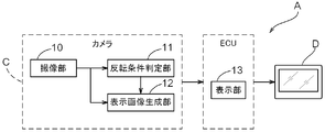
- FIG. 2 is a functional block diagram of the monitoring device A in the embodiment.
- the monitoring apparatus A captures the periphery of the vehicle V and generates a captured image, and a condition for determining whether the captured image captured by the imaging unit 10 is negative-positive-inverted (hereinafter, “inverted”).
- a reversal condition determination unit 11 that determines a condition
- a display image generation unit 12 that generates a negative / positive reversal image from the captured image when the reversal condition determination unit 11 determines that the reversal condition is satisfied
- a display A display unit 13 for displaying the display image generated by the image generation unit 12 on the display D is provided.
- the image pickup unit 10 is configured with an image sensor such as a CCD (Charge Coupled Device) sensor or a CMOS (Complementary Metal Oxide Semiconductor) sensor of the camera C, an image sensor driver, and an A / D converter as a core.
- an image sensor such as a CCD (Charge Coupled Device) sensor or a CMOS (Complementary Metal Oxide Semiconductor) sensor of the camera C
- an image sensor driver an A / D converter
- a / D converter As a core.
- Light incident from the lens of the camera C is photoelectrically converted by an image sensor and then A / D converted by an A / D converter or the like to generate a captured image.
- the captured image generated in this way is stored in a RAM in a DSP (Digital Signal Processor), and the fact that the captured image has been generated is sent to the inversion condition determination unit 11 and the display image generation unit 12.
- DSP Digital Signal Processor
- the reversal condition determination unit 11 is configured by the DSP of the camera C, and determines whether or not the captured image is negative / positive reversal based on a predetermined reversal condition. In the present embodiment, the inversion condition determination unit 11 performs determination based on the luminance value of the captured image (details will be described later).
- the display image generation unit 12 is configured by a DSP of the camera C, and generates a display image from the captured image based on the determination result of the inversion condition determination unit 11.
- the display image generation unit 12 When the inversion condition determination unit 11 determines that the inversion condition is satisfied, the display image generation unit 12 generates a negative / positive inversion image from the captured image as a display image.
- a negative / positive inversion image is an image obtained by performing at least a negative / positive inversion process on a photographed image, but in the present embodiment, a monochrome conversion process is also performed in consideration of ease of viewing. This monochrome conversion process may be performed before or after the negative / positive inversion process.
- the captured image is handled as a display image.
- the display image generation unit 12 can also have functions such as resolution conversion.
- the display image generated by the display image generation unit 12 is sent to the display unit 13.
- the display unit 13 includes an ECU and software mounted on the vehicle V, and has a function of displaying the display image generated by the display image generation unit 12 on the display D.
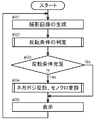
- FIG. 3 is a flowchart showing the flow of processing in this embodiment of the monitoring device.
- the imaging unit 10 is driven at a predetermined frame rate (for example, 30 fps), and a captured image is generated (# 01).
- the generated captured image is stored in the RAM of the camera C, and a notification to that effect is sent to the inversion condition determination unit 11.
- the captured image is sent to the display image generation unit 12.
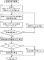
- the inversion condition determination unit 11 that has acquired the fact that the captured image has been generated from the imaging unit 10 determines whether or not a predetermined inversion condition is satisfied (# 02). Specifically, in the present embodiment, the processing shown in the flowchart of FIG. 4 is performed.
- the luminance histogram H is realized as an array having the same number of elements as the number of gradations of luminance values (in the following example, 256 gradations of 0 to 255).
- H [k] represents the frequency of the luminance value k.
- the captured image is a color image.
- a pixel of a color image has a pixel value composed of three values of a red (R) element, a green (G) element, and a blue (B) element. Therefore, the pixel value of the pixel p i is ⁇ R i , G i , B i ⁇ .
- the luminance value I i may be calculated using another calculation formula.
- the presence or absence of unprocessed pixels is checked (# 14). Specifically, it is determined whether or not the reference address q has reached the final address of the captured image in the RAM. If there is an unprocessed pixel (Yes branch of # 14), in order to shift the process to the next unprocessed pixel, the reference address q is incremented (# 15), and then the process proceeds to # 12. The above process is repeated.
- the luminance histogram H is created using all the pixels of the photographed image. However, only a part of the pixels of the photographed image may be used. In other words, this is a configuration using pixels in a specific range of the captured image.
- the feature amount of the captured image is calculated using the luminance histogram H generated by the above-described processing (# 16).
- Examples of the feature amount of the captured image that can be calculated from the luminance histogram H include average luminance, luminance dispersion, luminance histogram shape (unimodality, bimodality, etc.), and the like. In the present embodiment, description will be made using the average luminance. Therefore, the inversion condition determination unit 11 calculates the average luminance E [I] as the feature amount of the captured image by the following equation (1). In the present embodiment, it is assumed that the captured image is expressed by 8 bits for each color (RGB).
- the inversion condition determination unit 11 compares the average luminance E [I] calculated in this way with a predetermined threshold TH (# 17), and if the average luminance E [I] is smaller than the threshold TH (# 17 Yes branch), it is determined that the inversion condition is satisfied (# 18). On the other hand, if the average luminance E [I] is equal to or greater than the threshold value TH (No branch at # 17), it is determined that the inversion condition is not satisfied (# 19). The determination result of the inversion condition determination unit 11 is notified to the display image generation unit 12.
- the display image generation unit 12 that has acquired the determination result of the inversion condition determination unit 11 generates a display image from the captured image based on the determination result.
- the captured image acquired from the imaging unit 10 is stored in the RAM in the DSP.
- the display image generation unit 12 directly uses the captured image acquired from the imaging unit 10 as the display image on the display unit 13. send.
- the display image generation unit 12 performs negative / positive inversion and monochrome conversion on the captured image acquired from the imaging unit 10 (# 04). When a monochrome camera is used as the camera C, monochrome conversion is not necessary.
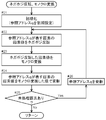
- FIG. 5 is a flowchart showing a flow of processing for generating a display image by performing negative / positive inversion and monochrome conversion on a captured image.
- the head address of the captured image in the RAM is set to the reference address q (# 21).
- the captured image is a color image composed of three RGB planes, and the pixel values of the pixels p i are ⁇ R i , G i , B i ⁇ . Each color has a value in the range of [0, 255]. Therefore, the pixel value of the pixel p i after negative / positive inversion is ⁇ 255 ⁇ R i , 255 ⁇ G i , 255 ⁇ B i ⁇ (# 22).
- the pixel value of the pixel p i is ⁇ I i , I i , I i ⁇ .
- the presence or absence of unprocessed pixels is checked (# 25). Specifically, it is determined whether or not the reference address q has reached the final address of the display image in the RAM. If there is an unprocessed pixel (Yes branch at # 25), the reference address q is incremented (# 26), and then the process proceeds to # 22 and the above process is repeated. On the other hand, when there is no unprocessed pixel (No branch of # 25), the display image generation process is terminated, and the generated display image is sent to the display unit 13.
- the display unit 13 that has acquired the display image from the display image generation unit 12 displays the display image on the display D (# 05).
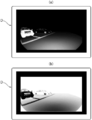
- FIG. 6A is an example of a photographed image when a dark part is photographed by the imaging unit 10.
- the inversion condition determination unit 11 determines that the inversion condition is satisfied, and the display image in FIG. 6B is generated.
- the dark part that is unknown in FIG. 6A is clear in FIG. 6B.
- FIG. 7 is a functional block diagram of the embodiment.
- symbol is attached
- the embodiment is different from the embodiment 1 in that the exposure control unit 14 is provided.
- the exposure control unit 14 is configured by a DSP of the camera C, calculates an appropriate gain value based on a captured image captured by the imaging unit 10, sets the calculated gain value in the imaging unit 10, and exposes the imaging unit 10. It has a function to perform control. The calculated gain value is also notified to the inversion condition determination unit 11.
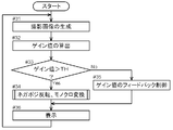
- the imaging unit 10 is driven at a predetermined frame rate, and a captured image is generated (# 31).
- the photographed image is stored in the RAM, and the fact is notified to the exposure control unit 14 and the inversion condition determination unit 11.
- the exposure control unit 14 Upon receipt of the notification that the photographed image has been generated, the exposure control unit 14 calculates an appropriate gain value by a known method (# 32). The calculated gain value is notified to the inversion condition determination unit 11.
- the inversion condition determination unit 11 compares the acquired gain value with a predetermined threshold value TH (# 33), and determines whether or not the captured image is to be negative / positive inverted.
- a predetermined threshold value TH (# 33)
- a captured image is generated by adjusting the gain value up to a gain value in front of which noise is conspicuous, and a gain value in which noise is conspicuous, that is, a gain value equal to or higher than threshold TH must be set. Then, a display image obtained by negative / positive reversal and monochrome conversion of the captured image is generated.
- the inversion condition determination unit 11 does not satisfy the inversion condition when the gain value is equal to or less than the threshold value TH (No branch of # 33). Therefore, the exposure control unit 14 performs the improvement of the image quality of the captured image by the exposure control. To the imaging unit 10 to feed back the gain value. In response to this, the exposure control unit 14 feeds back the calculated gain value to the imaging unit 10 and changes the gain value at the time of imaging in the imaging unit 10 thereafter (# 35). At the same time, the inversion condition determination unit 11 notifies the display image generation unit 12 that the inversion condition is not satisfied. In response to this, the display image generation unit 12 sends the captured image as it is to the display unit 13 as a display image.
- the display image generation unit 12 when the gain value is larger than the threshold value TH (Yes branch of # 33), the inversion condition is satisfied, so that the display image generation unit 12 is notified. In response to this, the display image generation unit 12 generates a display image by performing negative / positive inversion and monochrome conversion on the captured image (# 34). The generated display image is sent to the display unit 13. In this case, since the gain control for the imaging unit 10 is not executed from the exposure control unit 14, the gain value of the imaging unit 10 is a constant value (the gain value just before or set below the exposure control unit 14). Fixed.
- the display unit 13 that has acquired the display image displays the display image on the display D (# 36).
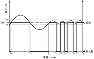
- FIG. 9 is a diagram illustrating the relationship between the gain value calculated by the exposure control unit 14 and the determination result of the inversion condition determination unit 11.
- the horizontal axis represents time
- the vertical axis represents the gain value calculated by the exposure control unit 14.
- the bold line in the figure indicates whether the inversion condition is satisfied, that is, whether negative / positive inversion is performed.
- the gain value is TH at time T 0
- the inversion condition is satisfied at this point.
- the gain value calculated by the exposure control unit 14 maintains the state exceeding the threshold value TH to the time T 1. Therefore, the display image is negative / positive inverted from time T 0 to T 1 .
- the inversion condition determination unit 11 changes the threshold value TH when it is determined that alternate display occurs. For example, when the threshold value is set to TH L , the gain value after time T 2 becomes larger than TH L , so that the inversion condition is continuously satisfied. Therefore, the time T 2, after image is displayed is negative-positive reversed, alternating display does not occur.
- the threshold value can be set to TH U which is larger than TH. In this case, the time T 2, after inversion conditions are not satisfied, display of an image is not negative-positive inversion continues.
- the exposure control unit 14 is configured by a DSP of the camera C, calculates an appropriate shutter speed (light accumulation time of the image sensor) based on a captured image captured by the imaging unit 10, and calculates the calculated shutter. By setting the speed to the imaging unit 10, it has a function of performing exposure control of the imaging unit 10. The calculated shutter speed is also notified to the inversion condition determination unit 11.
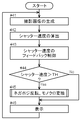
- the imaging unit 10 is driven at a predetermined frame rate, and a captured image is generated (# 41).
- the photographed image is stored in the RAM, and the fact is notified to the exposure control unit 14 and the inversion condition determination unit 11.
- the exposure control unit 14 Upon receipt of the notification that the captured image has been generated, the exposure control unit 14 calculates an appropriate shutter speed by a known method (# 42). The calculated shutter speed is notified to the inversion condition determination unit 11. At the same time, the exposure control unit 14 feeds back the calculated shutter speed to the imaging unit 10 in order to perform exposure control of the imaging unit 10 (# 43). In response to this, the imaging unit 10 changes the subsequent shutter speed.
- the inversion condition determination unit 11 compares the acquired shutter speed with a predetermined threshold value TH (# 44), and determines whether or not the captured image is to be negative / positive inverted. When the shutter speed is equal to or higher than the threshold value TH (Yes branch of # 43), the reversal condition determination unit 11 notifies the display image generation unit 12 that the reversal condition is satisfied. In response to this, the display image generation unit 12 generates a display image by negative / positive inversion and monochrome conversion of the captured image (# 45). The generated display image is sent to the display unit 13.
- the display image generation unit 12 when the shutter speed is smaller than the threshold value TH (No branch of # 43), the display image generation unit 12 is notified to that effect. In response to this, the display image generation unit 12 sends the captured image as it is to the display unit 13 as a display image.
- the display unit 13 that has acquired the display image displays the display image on the display D (# 46).
- inversion is performed so as to use the whole area of the pixel value definition area when negative / positive inversion is performed, but inversion may be performed so as to use a part of the definition area of the pixel value.
- the pixel value after inversion may be offset. For example, a pixel value p having a definition area of [0, 255] is negative / positive inverted by 255 ⁇ p + offset. At this time, if the offset is positive, the negative / positive inverted pixel value is shifted to the high luminance side, so the luminance value on the low luminance side is not used.
- the negative / positive-inverted pixel value is shifted to the low luminance side, so the high luminance side is not used.
- the pixel value exceeding the defined range is rounded to the maximum luminance value or the minimum luminance value.
- the value of this offset can be set as appropriate according to the environment used. For example, when the photographed image is very dark, the image becomes very bright when the negative / positive inversion is performed. Therefore, a negative offset is set to prevent overexposure. Further, when an LCD (Liquid Crystal Display) is used as the display D, low luminance may not be sufficiently expressed due to the characteristics of the LCD. In such a case, it is desirable to set a positive offset so that the pixel value that has been subjected to negative-positive inversion falls within a luminance range that can be expressed by the LCD.
- LCD Liquid Crystal Display
- the dynamic range of the negative / positive inverted pixel value may be compressed or expanded.
- the entire captured image is negative / positive inverted, but only a part of the captured image may be negative / positive inverted.
- the photographed image is not a part that is affected by the irradiation of the light L of the vehicle V (hereinafter referred to as a high luminance region)
- a portion not received hereinafter referred to as a low luminance region
- the entire captured image is negative-positive-inverted, the pixel value in the high luminance region becomes low luminance, and the display image is difficult to see for the driver.
- the pixels in the high luminance region are not negative / positive inverted, and only the pixels in the low luminance region are negative / positive inverted.
- the determination of the high luminance region and the low luminance region can also be performed by image processing. However, since these are defined by the positional relationship between the light L and the camera C, each region is set in advance. It does not matter. Further, in this case, since the color area as it is of the captured image and the monochrome area with negative / positive reversal mixed, it is desirable to clearly indicate these boundaries for the driver's ease of viewing.
- each functional unit of the monitoring device A is configured by the DSP of the camera C and the ECU mounted on the vehicle V, but is not limited to this configuration.
- it may be configured by only the ECU, or may be configured by a CPU and a program provided with a separate CPU (Central Processing Unit).
- CPU Central Processing Unit
- the present invention can be used for a monitoring device that monitors by displaying a low-brightness image of a dark part or the like.
Landscapes
- Engineering & Computer Science (AREA)
- Multimedia (AREA)
- Signal Processing (AREA)
- Mechanical Engineering (AREA)
- Closed-Circuit Television Systems (AREA)
- Studio Devices (AREA)
- Image Processing (AREA)
- Image Analysis (AREA)
Abstract
Priority Applications (4)
| Application Number | Priority Date | Filing Date | Title |
|---|---|---|---|
| CN201080021997.9A CN102428700B (zh) | 2009-05-20 | 2010-02-19 | 监视装置 |
| EP10777602.3A EP2434759B1 (fr) | 2009-05-20 | 2010-02-19 | Dispositif de surveillance |
| US13/265,669 US9001209B2 (en) | 2009-05-20 | 2010-02-19 | Monitoring apparatus |
| KR1020117026091A KR101367637B1 (ko) | 2009-05-20 | 2010-02-19 | 감시장치 |
Applications Claiming Priority (2)
| Application Number | Priority Date | Filing Date | Title |
|---|---|---|---|
| JP2009122131A JP5257695B2 (ja) | 2009-05-20 | 2009-05-20 | 監視装置 |
| JP2009-122131 | 2009-05-20 |
Publications (1)
| Publication Number | Publication Date |
|---|---|
| WO2010134366A1 true WO2010134366A1 (fr) | 2010-11-25 |
Family
ID=43126055
Family Applications (1)
| Application Number | Title | Priority Date | Filing Date |
|---|---|---|---|
| PCT/JP2010/052526 WO2010134366A1 (fr) | 2009-05-20 | 2010-02-19 | Dispositif de surveillance |
Country Status (6)
| Country | Link |
|---|---|
| US (1) | US9001209B2 (fr) |
| EP (1) | EP2434759B1 (fr) |
| JP (1) | JP5257695B2 (fr) |
| KR (1) | KR101367637B1 (fr) |
| CN (1) | CN102428700B (fr) |
| WO (1) | WO2010134366A1 (fr) |
Families Citing this family (15)
| Publication number | Priority date | Publication date | Assignee | Title |
|---|---|---|---|---|
| US9229233B2 (en) | 2014-02-11 | 2016-01-05 | Osterhout Group, Inc. | Micro Doppler presentations in head worn computing |
| CN103609101A (zh) * | 2011-06-16 | 2014-02-26 | 爱信精机株式会社 | 车辆周边监视装置 |
| JP6281289B2 (ja) * | 2014-01-10 | 2018-02-21 | アイシン精機株式会社 | 周辺監視装置、及びプログラム |
| US20150228119A1 (en) | 2014-02-11 | 2015-08-13 | Osterhout Group, Inc. | Spatial location presentation in head worn computing |
| US9753288B2 (en) | 2014-01-21 | 2017-09-05 | Osterhout Group, Inc. | See-through computer display systems |
| US9766463B2 (en) | 2014-01-21 | 2017-09-19 | Osterhout Group, Inc. | See-through computer display systems |
| US9852545B2 (en) | 2014-02-11 | 2017-12-26 | Osterhout Group, Inc. | Spatial location presentation in head worn computing |
| US20160187651A1 (en) | 2014-03-28 | 2016-06-30 | Osterhout Group, Inc. | Safety for a vehicle operator with an hmd |
| JP6206334B2 (ja) * | 2014-06-10 | 2017-10-04 | 株式会社デンソー | 検出装置 |
| US20160239985A1 (en) | 2015-02-17 | 2016-08-18 | Osterhout Group, Inc. | See-through computer display systems |
| US10878775B2 (en) * | 2015-02-17 | 2020-12-29 | Mentor Acquisition One, Llc | See-through computer display systems |
| US10591728B2 (en) | 2016-03-02 | 2020-03-17 | Mentor Acquisition One, Llc | Optical systems for head-worn computers |
| US10667981B2 (en) | 2016-02-29 | 2020-06-02 | Mentor Acquisition One, Llc | Reading assistance system for visually impaired |
| EP3854632B1 (fr) * | 2017-06-09 | 2023-05-31 | Koito Manufacturing Co., Ltd. | Dispositif et procédé pour générer des données de commande d'intensité lumineuse dans une lampe pour automobile |
| JP6855131B2 (ja) * | 2017-07-10 | 2021-04-07 | アルパイン株式会社 | 地図画面表示装置、明るさ調整用パラメータ算出装置および地図画面表示方法 |
Citations (8)
| Publication number | Priority date | Publication date | Assignee | Title |
|---|---|---|---|---|
| JPH099142A (ja) * | 1995-06-23 | 1997-01-10 | Fuji Photo Film Co Ltd | フイルム画像処理方法 |
| JPH11146389A (ja) * | 1997-11-04 | 1999-05-28 | Nissan Motor Co Ltd | 表示装置 |
| JPH11243538A (ja) * | 1998-02-25 | 1999-09-07 | Nissan Motor Co Ltd | 車両用視認装置 |
| JP2001359108A (ja) * | 2000-06-15 | 2001-12-26 | Fuji Photo Film Co Ltd | 携帯型撮像装置およびその動作制御方法 |
| JP2003324748A (ja) | 2002-05-08 | 2003-11-14 | Hitachi Kokusai Electric Inc | テレビジョンカメラ |
| JP2005303442A (ja) * | 2004-04-07 | 2005-10-27 | Honda Motor Co Ltd | 車両用視覚支援装置 |
| JP2008201202A (ja) | 2007-02-19 | 2008-09-04 | Hitachi Ltd | 車両用側方監視カメラシステム |
| JP2008230464A (ja) | 2007-03-22 | 2008-10-02 | Alpine Electronics Inc | 車載カメラ用自動露出装置 |
Family Cites Families (7)
| Publication number | Priority date | Publication date | Assignee | Title |
|---|---|---|---|---|
| US6795521B2 (en) * | 2001-08-17 | 2004-09-21 | Deus Technologies Llc | Computer-aided diagnosis system for thoracic computer tomography images |
| JP3682482B2 (ja) * | 2002-04-24 | 2005-08-10 | コニカミノルタフォトイメージング株式会社 | 撮像装置 |
| US6853806B2 (en) | 2002-09-13 | 2005-02-08 | Olympus Optical Co., Ltd. | Camera with an exposure control function |
| CN1263280C (zh) | 2002-11-05 | 2006-07-05 | 奥林巴斯株式会社 | 照相机 |
| JP2005145217A (ja) * | 2003-11-14 | 2005-06-09 | Auto Network Gijutsu Kenkyusho:Kk | 車載表示装置及び車両周辺監視装置 |
| JP2006074710A (ja) * | 2004-08-04 | 2006-03-16 | Konica Minolta Photo Imaging Inc | デジタルカメラ及びカメラシステム |
| US8023710B2 (en) * | 2007-02-12 | 2011-09-20 | The United States Of America As Represented By The Secretary Of The Department Of Health And Human Services | Virtual colonoscopy via wavelets |
-
2009
- 2009-05-20 JP JP2009122131A patent/JP5257695B2/ja not_active Expired - Fee Related
-
2010
- 2010-02-19 EP EP10777602.3A patent/EP2434759B1/fr not_active Not-in-force
- 2010-02-19 WO PCT/JP2010/052526 patent/WO2010134366A1/fr active Application Filing
- 2010-02-19 CN CN201080021997.9A patent/CN102428700B/zh not_active Expired - Fee Related
- 2010-02-19 KR KR1020117026091A patent/KR101367637B1/ko active IP Right Grant
- 2010-02-19 US US13/265,669 patent/US9001209B2/en not_active Expired - Fee Related
Patent Citations (8)
| Publication number | Priority date | Publication date | Assignee | Title |
|---|---|---|---|---|
| JPH099142A (ja) * | 1995-06-23 | 1997-01-10 | Fuji Photo Film Co Ltd | フイルム画像処理方法 |
| JPH11146389A (ja) * | 1997-11-04 | 1999-05-28 | Nissan Motor Co Ltd | 表示装置 |
| JPH11243538A (ja) * | 1998-02-25 | 1999-09-07 | Nissan Motor Co Ltd | 車両用視認装置 |
| JP2001359108A (ja) * | 2000-06-15 | 2001-12-26 | Fuji Photo Film Co Ltd | 携帯型撮像装置およびその動作制御方法 |
| JP2003324748A (ja) | 2002-05-08 | 2003-11-14 | Hitachi Kokusai Electric Inc | テレビジョンカメラ |
| JP2005303442A (ja) * | 2004-04-07 | 2005-10-27 | Honda Motor Co Ltd | 車両用視覚支援装置 |
| JP2008201202A (ja) | 2007-02-19 | 2008-09-04 | Hitachi Ltd | 車両用側方監視カメラシステム |
| JP2008230464A (ja) | 2007-03-22 | 2008-10-02 | Alpine Electronics Inc | 車載カメラ用自動露出装置 |
Non-Patent Citations (1)
| Title |
|---|
| See also references of EP2434759A4 |
Also Published As
| Publication number | Publication date |
|---|---|
| US9001209B2 (en) | 2015-04-07 |
| EP2434759A4 (fr) | 2012-09-05 |
| JP2010273026A (ja) | 2010-12-02 |
| EP2434759B1 (fr) | 2016-05-11 |
| KR20120008519A (ko) | 2012-01-30 |
| JP5257695B2 (ja) | 2013-08-07 |
| EP2434759A1 (fr) | 2012-03-28 |
| CN102428700A (zh) | 2012-04-25 |
| CN102428700B (zh) | 2014-12-17 |
| US20120033080A1 (en) | 2012-02-09 |
| KR101367637B1 (ko) | 2014-02-27 |
Similar Documents
| Publication | Publication Date | Title |
|---|---|---|
| JP5257695B2 (ja) | 監視装置 | |
| JP4706466B2 (ja) | 撮像装置 | |
| EP2833618A2 (fr) | Procédé permettant d'activer et de désactiver une fonction de correction d'image, système de caméra et véhicule à moteur | |
| JP6319340B2 (ja) | 動画撮像装置 | |
| US7817190B2 (en) | Method and apparatus for processing an image exposed to backlight | |
| US10560638B2 (en) | Imaging apparatus and imaging method | |
| JP4952499B2 (ja) | 画像処理装置 | |
| EP1557790A2 (fr) | Réduction de bruit dans une image à illumination réduite | |
| JP2013223152A (ja) | 撮像装置 | |
| JP4798945B2 (ja) | 撮像装置 | |
| EP1530367A1 (fr) | Systeme de prise de vue | |
| JP2008230464A (ja) | 車載カメラ用自動露出装置 | |
| JP2012010282A (ja) | 撮像装置、露光制御方法及び露光制御プログラム | |
| KR101091913B1 (ko) | 촬영장치의 역광보정방법 | |
| JP5585808B2 (ja) | 監視装置 | |
| JP5520863B2 (ja) | 画像信号処理装置 | |
| JP2011135379A (ja) | 撮像装置、撮像方法及びプログラム | |
| JP2007013687A (ja) | 液晶シャッタによるアイリス調整機能付き撮像装置 | |
| JP2007235421A (ja) | 撮像装置 | |
| WO2023026617A1 (fr) | Dispositif d'imagerie et système d'affichage vidéo | |
| JP2002268116A (ja) | 自動露出制御装置およびそのプログラムを組み込んだ外部記憶媒体 | |
| JP4677924B2 (ja) | 撮影システム、動画像処理方法および動画像処理装置 | |
| WO2022059139A1 (fr) | Dispositif d'affichage d'image et procédé d'affichage d'image | |
| KR101691043B1 (ko) | 적외선을 이용하여 야간 컬러영상을 구현하는 폐쇄회로 텔레비전 카메라 | |
| JP2004221888A (ja) | 撮像装置 |
Legal Events
| Date | Code | Title | Description |
|---|---|---|---|
| WWE | Wipo information: entry into national phase |
Ref document number: 201080021997.9 Country of ref document: CN |
|
| 121 | Ep: the epo has been informed by wipo that ep was designated in this application |
Ref document number: 10777602 Country of ref document: EP Kind code of ref document: A1 |
|
| WWE | Wipo information: entry into national phase |
Ref document number: 2010777602 Country of ref document: EP |
|
| WWE | Wipo information: entry into national phase |
Ref document number: 8096/DELNP/2011 Country of ref document: IN |
|
| WWE | Wipo information: entry into national phase |
Ref document number: 13265669 Country of ref document: US |
|
| ENP | Entry into the national phase |
Ref document number: 20117026091 Country of ref document: KR Kind code of ref document: A |
|
| NENP | Non-entry into the national phase |
Ref country code: DE |