WO2010134200A1 - 画像処理装置、方法及びプログラム - Google Patents
画像処理装置、方法及びプログラム Download PDFInfo
- Publication number
- WO2010134200A1 WO2010134200A1 PCT/JP2009/059454 JP2009059454W WO2010134200A1 WO 2010134200 A1 WO2010134200 A1 WO 2010134200A1 JP 2009059454 W JP2009059454 W JP 2009059454W WO 2010134200 A1 WO2010134200 A1 WO 2010134200A1
- Authority
- WO
- WIPO (PCT)
- Prior art keywords
- image
- determination unit
- face
- determination
- state
- Prior art date
- Legal status (The legal status is an assumption and is not a legal conclusion. Google has not performed a legal analysis and makes no representation as to the accuracy of the status listed.)
- Ceased
Links
Images
Classifications
-
- G—PHYSICS
- G06—COMPUTING OR CALCULATING; COUNTING
- G06T—IMAGE DATA PROCESSING OR GENERATION, IN GENERAL
- G06T7/00—Image analysis
- G06T7/70—Determining position or orientation of objects or cameras
- G06T7/73—Determining position or orientation of objects or cameras using feature-based methods
-
- G—PHYSICS
- G06—COMPUTING OR CALCULATING; COUNTING
- G06T—IMAGE DATA PROCESSING OR GENERATION, IN GENERAL
- G06T2207/00—Indexing scheme for image analysis or image enhancement
- G06T2207/30—Subject of image; Context of image processing
- G06T2207/30196—Human being; Person
- G06T2207/30201—Face
Definitions
- the present invention relates to image processing.
- Patent Document 1 discloses face authentication in which an image of a face in which an eye area and a mouth area move in the same manner, extracted from a plurality of frames of images, is determined as a spoofed image such as a photographic image. The technology is disclosed.
- Patent Document 2 Japanese Patent Laid-Open No. 2007-304801 detects face feature points from two face images with different face orientations and determines whether the shape formed by the face feature points is a three-dimensional object. The technology is disclosed.
- Patent Document 1 since only two-dimensional information is used, it is difficult to distinguish in principle whether it is a photograph or a three-dimensional object.
- Patent Document 2 depending on the position of a captured face image, the posture of a person, and the like, it may be erroneously determined that the shape formed by the face feature points is not a three-dimensional object.
- the present invention has been made in view of the above background, and an object thereof is to reduce misjudgment in the three-dimensional judgment of a face image.
- whether or not the state of the face image included in the image at one time among the images acquired at a plurality of different times is a preparation state that satisfies the condition for performing the stereoscopic determination.
- a start determination unit that determines whether or not a state of a face image included in an image at another time different from the image at the one time is a start state changed from the preparation state;
- a first 3D determination unit that performs the 3D determination of the face image included in the acquired image when it is determined as the start state.
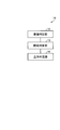
- FIG. 1 is a block diagram showing a configuration of an image processing apparatus according to a first embodiment.
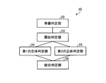
- the block diagram which shows the structure of the image processing apparatus which concerns on 2nd Embodiment.
- FIG. 1 is a block diagram showing a configuration of an image processing apparatus 10 according to the first embodiment of the present invention.
- the preparation determination unit 12 determines whether the state of the face image included in the image at one time among the plurality of images acquired at different times from the image input unit 55 described later satisfies the condition for performing the stereoscopic determination. Determine whether or not.
- the preparation determination unit 12 determines whether or not the state of the face image included in the image at another time different from the image at the one time is a preparation state. For example, the preparation determination unit 12 may determine that the state is “preparation state” when all of the following three conditions are satisfied.
- the present invention is not limited to this, and at least one of the following three conditions is satisfied. It may satisfy.
- Condition 1 The size of the face is within the set range.
- Condition 2 The face orientation is within the set range including the front.
- Condition 3 The amount of movement of the face is within the set range (still).
- the preparation determination unit 12 detects face feature points from the image acquired by the image input unit 55 in order to determine whether or not the preparation state is in effect.
- the preparation determination unit 12 can detect a feature point using, for example, a method disclosed in Non-Patent Document 1. A process in which the preparation determination unit 12 performs the determination from Condition 1 to Condition 3 using the feature points will be described below.
- condition 1 for example, the distance between the center points of the pupils among the detected feature points is measured, for example, and it is determined whether or not the distance is within a preset range.
- the orientation of the face is measured using the detected feature points, and the determination is made based on whether or not the orientation is close to the front direction with respect to the image input unit 55.
- the method disclosed in Japanese Patent Application Laid-Open No. 2003-141551 can be used for measuring the face orientation.
- the three-dimensional shape may be obtained from the input moving image using the factorization method disclosed in Non-Patent Document 2, or a standard shape model prepared in advance may be used.
- a standard face shape is used is exemplarily shown.
- the camera motion matrix corresponds to the rotation matrix except for the scale, and if the rotation matrix is known, rotation in three directions can be obtained.
- the camera motion matrix is a 3 ⁇ 2 matrix, and the rotation matrix needs to be complemented to obtain a 3 ⁇ 3 rotation matrix.
- Rotation matrix is expressed as a 3x3 square matrix and has 9 components.
- the degree of freedom of the rotation matrix is 3, and if some components are given, the remaining components may be uniquely determined. In that case, all components can be obtained by elementary calculation.
- a quaternion equivalent to the rotation matrix is calculated using the six components in the upper two rows.
- the relational expression between the rotation matrix and the quaternion is described in Non-Patent Document 3, for example, and the quaternion can be obtained by elementary calculation using the relational expression.
- the component of the bottom row of the rotation matrix is calculated again using the relational expression between the rotation matrix and the quaternion. If the 3 ⁇ 3 rotation matrix is obtained in this way, the rotation angle of the three axes can be obtained therefrom.
- the determination condition may be that each angle is smaller than a preset threshold value.
- the threshold value is 15 degrees.
- the determination of the condition 3 for example, when the average value and the maximum value of the motion amount of the feature points are smaller than a preset motion amount, it is determined that the camera is stationary. For example, a difference from the previous frame is used as the amount of motion.
- the condition may be presented to the target person. For example, if the size of the face is smaller than the preset size, you may present the status as “face is too small” or prompt the action that satisfies the condition, such as “close to the camera” Things may be presented.
- the presenting method includes a method of displaying as a character on a display, presenting with voice, and presenting with a change in light such as an LED.
- filling conditions when satisfy
- the start determination unit 13 determines that there is a change in the state of the face image in an image at a time different from the image determined by the preparation determination unit 12. More specifically, the state is “started” when the amount of motion of the detected feature point is larger than the set value. “Determining that the current state is the start state” is referred to as “start determination”.
- start determination the motion amount is a difference between the coordinates of the feature point at the time when the preparation determination is completed and the coordinates of the feature point at the time of determination.
- a presentation that encourages movement may be shown. Further, it is desirable to return to the preparation determination again when the condition is not satisfied even after a predetermined time has elapsed.
- the solid determination unit 14 determines that the object in the acquired image is a solid.
- the solid determination unit 14 may use the method disclosed in Patent Document 2.
- face feature points are detected for two face images taken with different face orientations, and it is determined whether the shape formed by the face feature points is planar or three-dimensional.
- a face image in a ready state and a face image in a start state may be used as the two face images.
- the face feature points that have already been detected by the preparation determination unit 12 and the start determination unit 13 can be used.
- the presentation unit 56 presents a message indicating that it is not suitable for impersonation determination.
- the presentation unit 56 may present a message requesting input of a new face image. With this message, an operator who performs face authentication can input a face image satisfying a condition to an imaging unit (not shown).
- the presentation unit 56 also presents a message indicating that the face image input to the start determination unit 13 is not suitable for stereoscopic determination when there is no movement with respect to the face image that has been determined to be ready.
- the presentation unit 56 may present a message requesting input of a new face image. With this message, an operator who performs face authentication can input a face image satisfying a condition to an imaging unit (not shown).
- the presenting unit 56 may present the message to the operator who performs face authentication by voice or light.
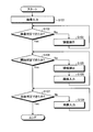
- FIG. 2 is a flowchart showing the operation of the image processing apparatus 10.
- an image input unit 55 described later sequentially inputs time-series images.
- the preparation determination unit 12 performs preparation determination on the face image in the time-series image input from the image input unit 55. If the preparation determination can be made, the process proceeds to step S104. If the preparation determination cannot be performed, the process proceeds to step S103.
- step S103 the presentation unit 56 presents a message indicating that it is not suitable for impersonation determination. After the process of step S103, the process returns to step S102 and is repeated.
- step S104 the start determination unit 13 performs start determination on a face image at a time different from the face image determined to be ready. If the start determination can be made, the process proceeds to step S107. If the start determination cannot be made, the process proceeds to step S105.
- step S105 the presentation unit 56 presents a message indicating that it is not suitable for the solid determination.
- step S106 an image at a new time is input from the image input unit 55, and the process returns to step S104 to repeat the process.
- step S107 the solid determination unit 14 performs a solid determination. If a three-dimensional determination is made, the process ends. On the other hand, if the three-dimensional determination is not made, the process proceeds to step S108, and a new image is acquired. It progresses to step S107 after step S108, and a process is repeated.
- step S107 the process may be repeated by returning to step S101.
- the preparation determination unit 12 determines that the subject is in a state suitable for impersonation determination, and the start determination unit 13 determines that there is a change from the preparation state. By determining, a state suitable for determination can be acquired in the subsequent three-dimensional determination unit 14, and erroneous determination in impersonation determination can be reduced.
- FIG. 3 is a block diagram showing the configuration of the image processing apparatus 20 according to the second embodiment of the present invention.
- the image processing apparatus 20 includes a second solid determination unit and an integrated determination unit in addition to the configuration of the image processing apparatus 10 of the first embodiment.
- impersonation determination is performed by a single solid determination unit 14.
- the accuracy is further improved by combining a plurality of methods having different properties.
- the processing of the image input unit 55, the preparation determination unit 22, the start determination unit 23, and the presentation unit 56 is performed by the image input unit 55, the preparation determination unit 12, the start determination unit 13, and the like. And it is the same as the process of the presentation part 56.
- the first three-dimensional determination unit 24 and the second three-dimensional determination unit 25 each perform a three-dimensional determination process.
- the first solid determination unit 24 performs the determination using the same method as in the first embodiment.
- the second three-dimensional determination unit 25 for example, a method based on change detection of a normalized image of a face is used.
- the face normalization image is obtained by aligning face images in a certain size and orientation using the coordinates of detected feature points. For example, normalization is performed by affine transformation using the coordinates of the two points of the pupil center and the nostril midpoint. When such normalization is performed, if the target is a photograph, the same normalized image can be obtained by any shooting method. Due to the variation, a change is obtained in the normalized image.
- the degree of similarity between the average image and each normalized image is obtained by, for example, normalized correlation, and if the degree of similarity exceeds a set value, it is determined to be a three-dimensional image. .
- the average image is the average image at the time of preparation determination, a more stable average image can be obtained.
- the integrated determination unit 26 comprehensively determines from the determination results for each frame in the first and second solid determination units.
- the first solid determination unit 24 and the second solid determination unit 25 use different methods for determination. For example, in the above example, the first solid determination unit 24 performs determination based on the positional relationship of the feature point coordinates, and the second solid determination unit 25 performs solid determination based on fluctuations in the normalized image. For this reason, depending on the input face image, either one may be determined earlier, or only one may be determined.
- the integrated determination unit 26 outputs a determination result indicating that the face of the face image is a solid when any one of the three-dimensional determination units determines that the face is a solid. In addition, when a frame that is not determined to be a solid continues for a certain period, it is determined that the frame is not a solid.
- impersonation that cannot be determined by one of the two types of solid determination units can be determined by making up for each defect. This makes it possible to reduce erroneous determinations in impersonation determination. Further, by outputting the determination result when the determination result of the solid determination unit with the earlier determination timing is output, the determination can be made in a shorter time than when a single solid determination unit is used, and the user waits. Time is shortened.
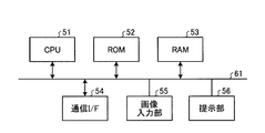
- FIG. 4 is a diagram showing a hardware configuration of a computer having the image processing apparatus according to the embodiment of the present invention.
- the image input unit 55 is configured to sequentially input time-series images. In addition to the time-series images, for example, images captured at two or more times may be input as the input images.
- the CPU 51 controls each part of the computer. Storage devices such as the ROM 52 and the RAM 53 store programs and data.
- the communication I / F 54 is communicably connected to the network.
- the bus 61 connects each part of the computer so that communication is possible.
- the CPU 51 reads and executes a program stored in a storage medium such as the ROM 52. Thereby, the function of each part of the image processing apparatus according to the embodiment of the present invention described above is realized by a computer.
- the program executed by the image processing apparatus can be provided by being incorporated in the ROM 52 or the like.
- the program executed by the image processing apparatus is provided in a form that can be installed or executable and recorded on a computer-readable recording medium such as a CD-ROM, a flexible disk (FD), a CD-R, or a DVD. Can be done.
- a computer-readable recording medium such as a CD-ROM, a flexible disk (FD), a CD-R, or a DVD. Can be done.
- the program executed by the image processing apparatus may be stored in a storage medium connected to a network such as the Internet and provided via a transmission medium such as a network.
- the motion amount of the feature point is used for motion determination, but the present invention is not limited to this.
- the change amount of the face direction obtained for the determination of the condition 2 for the preparation determination may be obtained.
- the conditions when the preparation determination unit 12 and the preparation determination unit 22 determine are not limited to the above embodiment. Other conditions, for example, whether or not the image is blurred may be determined, and the condition may be that the image is not blurred.
- the number of three-dimensional determination units in the second embodiment is not limited to two. It may be more. Moreover, the solid determination part in 1st, 2nd embodiment is not restricted to these, Another method may be sufficient. Further, instead of the solid determination, a means for performing a biological determination may be used.
- three-point affine transformation is used as the normalized image, but the invention is not limited thereto. Any one that can normalize the position, size, or orientation is acceptable.
- the integrated determination unit 26 has been determined to be a solid. It is not limited to that. Other determination methods may be used. For example, each determination unit may output a solidness score for each frame and comprehensively determine from the values. For example, when the sum of scores exceeds a preset threshold value, it may be determined as a solid.
- the present invention is not limited to the above-described embodiment as it is, and can be embodied by modifying constituent elements without departing from the scope of the invention in the implementation stage.
- various inventions can be formed by appropriately combining a plurality of components disclosed in the embodiment. For example, some components may be deleted from all the components shown in the embodiment.
- constituent elements over different embodiments may be appropriately combined.
Landscapes
- Engineering & Computer Science (AREA)
- Computer Vision & Pattern Recognition (AREA)
- Physics & Mathematics (AREA)
- General Physics & Mathematics (AREA)
- Theoretical Computer Science (AREA)
- Image Analysis (AREA)
- Image Processing (AREA)
Abstract
顔画像の立体判定における誤判定を低減する画像処理装置、方法及びプログラムを提供する。画像処理装置は、異なる複数の時刻に取得した画像のうち一の時刻の画像に含まれる顔画像の状態が、立体判定を行う条件を満たす準備状態であるか否かを判定する準備判定部12と、前記一の時刻の画像と異なる他の時刻の画像に含まれる顔画像の状態が、前記準備状態から変化した開始状態であるか否かを判定する開始判定部13と、前記開始状態であると判定した場合に、前記取得した画像に含まれる顔画像の前記立体判定を行う第1の立体判定部14と、を有する。
Description
本発明は、画像処理に関する。
従来から、取得した顔画像を用いてなりすましを判定する技術がある。
特開2006-330936号公報(特許文献1)は、複数フレームの画像から抽出した、目領域、及び、口領域が同じ動きをする顔の画像を、写真画像等によるなりすまし画像と判定する顔認証技術を開示している。
特開2007-304801号公報(特許文献2)は、撮影した顔の向きが異なる2つの顔画像から顔特徴点を検出し、顔特徴点が形作る形状が立体物であるか否かを判定する技術を開示している。
「静止画顔認証のための自動顔特徴点検出」, 湯浅 他、電子情報通信学会研究報告, PRMU2006-222, pp.5-10, Feb. 2007.
C. Tomasi and T. Kanade, "Shape and motion from image streams under orthography: a factorization method," International Journal of Computer Vision, vol. 9, no. 2, pp.137-154, 1992.
徐剛、辻三郎著、3次元ビジョン(共立出版、1998年) pp.22
しかしながら、特許文献1の技術では、2次元的な情報のみを利用しているため、写真か立体物かを原理的に区別することは難しかった。また、特許文献2の技術では、撮影した顔画像の位置や人物の姿勢などによっては、顔特徴点が形作る形状が立体物でないと誤判定されることがあった。
本発明は、上記の背景に鑑みてなされたものであり、顔画像の立体判定における誤判定を低減することを目的とする。
本発明の一態様に係る画像処理装置は、異なる複数の時刻に取得した画像のうち一の時刻の画像に含まれる顔画像の状態が、立体判定を行う条件を満たす準備状態であるか否かを判定する準備判定部と、前記一の時刻の画像と異なる他の時刻の画像に含まれる顔画像の状態が、前記準備状態から変化した開始状態であるか否かを判定する開始判定部と、前記開始状態であると判定した場合に、前記取得した画像に含まれる顔画像の前記立体判定を行う第1の立体判定部と、を備える。
本発明によれば、顔画像の立体判定における誤判定を低減することができる。
以下、本発明の実施の形態を添付図面を参照して説明する。
(第1の実施形態)
図1は、本発明の第1の実施形態に係る画像処理装置10の構成を示すブロック図である。
図1は、本発明の第1の実施形態に係る画像処理装置10の構成を示すブロック図である。
準備判定部12は、後述する画像入力部55から異なる複数の時刻に取得した複数の画像のうち一の時刻における画像に含まれている顔画像の状態が、立体判定を行う条件を満たしているか否かを判定する。準備判定部12は、一の時刻の画像と異なる他の時刻の画像に含まれる顔画像の状態が、準備状態であるか否かを判定する。準備判定部12は、例えば、以下の3つの条件のすべてを満たす場合に「準備状態である」と判定すればよいが、本発明はこれに限定されず、以下の3つの条件の少なくとも1つ満たすものであってもよい。
条件1:顔の大きさが設定範囲内にある。
条件2:顔の向きが正面を含む設定範囲内にある。
条件3:顔の動き量が設定範囲内にある(静止している)。
条件2:顔の向きが正面を含む設定範囲内にある。
条件3:顔の動き量が設定範囲内にある(静止している)。
準備判定部12は、準備状態であるか否かを判定するために、画像入力部55で取得した画像から顔特徴点を検出する。準備判定部12は、例えば、非特許文献1に開示されている方法を用いて特徴点を検出することができる。準備判定部12が、特徴点を用いて、条件1から条件3の判定を行う処理について、以下説明する。
条件1の判定では、例えば、検出された特徴点のうち、例えば瞳の中心点の間の距離を測定し、その距離が予め設定された範囲内にあるか否かを判定する。
条件2の判定では、例えば、検出された特徴点を使用して顔の向きを測定し、その向きが画像入力部55に対する正面の向きに近いかどうかで判定を行なう。顔の向きの測定には、例えば特開2003-141551号公報に開示された方法を用いることができる。
ここで、3次元形状は非特許文献2に開示された因子分解法を用いて入力動画から求めてもよいし、予め準備した標準的な形状モデルを用いてもよい。本実施形態においては、標準顔形状を用いる場合を例示的に示す。
次にカメラ運動行列から顔向きの角度を求める。カメラ運動行列はスケールを除けば回転行列に対応し、回転行列がわかれば3方向の回転を求めることができる。しかしながら、カメラ運動行列は3×2の行列であり、3×3の回転行列を求めるには回転行列の補完が必要である。
回転行列は3×3の正方行列で表現され、9つの成分を持つ。回転行列の自由度は3であり、一部の成分が与えられれば残りの成分も一意的に決められる場合がある。その場合は初等計算により全ての成分を求めることができる。
回転行列の上2行の6つの成分が誤差を含んだ状態で与えられたときに、残りの最下行の3個の成分を補完して完全な回転行列を求めるには、次の(1)から(4)の処理を行う。
(1)第1行と第2行の行ベクトルを、それぞれ方向を変えずにノルムが1になるように修正する。
(2)第1行の行ベクトルと第2行の行ベクトルの内積が0になるようにそれぞれのベクトルの長さを変えずに方向だけを修正する。このとき、2つのベクトルの平均ベクトルの方向が変わらないようにする。
(2)第1行の行ベクトルと第2行の行ベクトルの内積が0になるようにそれぞれのベクトルの長さを変えずに方向だけを修正する。このとき、2つのベクトルの平均ベクトルの方向が変わらないようにする。
(3)上2行の6つの成分を用いて、回転行列と等価な4元数を計算する。回転行列と4元数との関係式は、例えば、非特許文献3に説明されており、その関係式を用いて初等計算で4元数を求めることができる。
(4)求めた4元数から、再度、回転行列と4元数との関係式を用いて、回転行列の最下行の成分を計算して求める。このようにして3×3の回転行列が求まれば、それから3軸の回転角を求めることができる。
(4)求めた4元数から、再度、回転行列と4元数との関係式を用いて、回転行列の最下行の成分を計算して求める。このようにして3×3の回転行列が求まれば、それから3軸の回転角を求めることができる。
3つの回転角をそれぞれ左右、上下、傾きとすると、判定条件としては、それぞれの角度が予め設定されたしきい値より小さいとすればよい。しきい値としては例えば15度などとする。条件3の判定には、例えば、特徴点の動き量の平均値、最大値などが予め設定された動き量より小さい場合に、静止していると判定する。動き量は例えば前のフレームからの差を用いる。
準備判定において、条件を満たさない場合には、その条件を対象者に提示してもよい。例えば顔の大きさが予め設定されたサイズよりも小さい場合には、「顔が小さすぎます」と状態を提示してもよいし、「カメラに近づいてください」など、条件を満たす行動を促すものを提示してもよい。提示方法は、ディスプレイに文字として表示する、音声で提示する、LEDなどの光の変化で提示するといった方法ある。また、条件を満たさない場合のみでなく、条件を満たした場合に、その結果を提示してもよい。例えば「準備完了」などと提示してもよい。また、条件が複数ある場合には、それぞれについて準備ができているかどうかを個別に提示してもよい。
以上が、準備判定部12により実行される処理である。
開始判定部13は、準備判定部12により判定された画像と異なる時刻の画像において、顔画像の状態の変化があることを判定する。より詳細には、検出された特徴点の動き量が設定値より大きい場合に「開始状態である」とする。また「開始状態であると判定すること」を「開始判定」という。ここで、動き量は、準備判定が完了した時点の特徴点の座標と、判定する時点の特徴点の座標との差である。
開始判定において、条件を満たさない場合には、動きを促すような提示を示してもよい。また、一定時間経過しても条件が満たされない場合は再度準備判定に戻るのが望ましい。
立体判定部14は、取得した画像中の対象物が立体であることを判定する。立体判定部14は、例えば、特許文献2に開示の方法を用いるとよい。特許文献2では、撮影した顔向きの異なる2つの顔画像に対して顔特徴点を検出し、顔特徴点が形作る形状が平面的であるか3次元的であるかを判定する。このとき、2つの顔画像には、準備判定できた状態の顔画像と、開始判定できた状態の顔画像を用いればよい。また、顔特徴点は、準備判定部12、開始判定部13がすでに検出したものを用いることが可能である。
提示部56は、準備判定部12が、入力された顔画像がなりすまし判定に適した状態ではないと判定した場合に、なりすまし判定に適していない旨のメッセージを提示する。提示部56は、また、新たな顔画像の入力を求めるメッセージを提示してもよい。このメッセージにより、顔認証を行う操作者が、図示しない撮像部に対して条件を満たす顔画像を入力するようにすることができる。
提示部56は、また、開始判定部13に入力された顔画像が、準備判定された顔画像に対する動きがない場合に、立体判定に適していない旨のメッセージを提示する。提示部56は、また、新たな顔画像の入力を求めるメッセージを提示してもよい。このメッセージにより、顔認証を行う操作者が、図示しない撮像部に対して条件を満たす顔画像を入力するようにすることができる。
なお、提示部56は、メッセージを表示部に表示する他に、音声又は光等により、顔認証を行う操作者に対する提示を行ってもよい。
図2は、画像処理装置10の動作を示すフローチャートである。図2のステップS101では、後述する画像入力部55が、時系列の画像を逐次入力する。ステップS102では、準備判定部12が、画像入力部55から入力された時系列の画像中の顔画像に対し、準備判定を行う。準備判定ができた場合には、ステップS104に進み、準備判定ができない場合には、ステップS103に進む。
ステップS103では、提示部56が、なりすまし判定に適していない旨のメッセージ等を提示する。ステップS103の処理の後、ステップS102に戻って処理を繰り返す。
ステップS104では、開始判定部13が、準備判定された顔画像と異なる時刻の顔画像に対し、開始判定を行う。開始判定ができた場合には、ステップS107に進み、開始判定ができない場合には、ステップS105に進む。
ステップS105では、提示部56が、立体判定に適していない旨のメッセージ等を提示する。ステップS106では、画像入力部55から、新たな時刻の画像が入力され、ステップS104に戻って処理を繰り返す。
ステップS107では、立体判定部14が、立体判定を行う。立体判定がなされた場合には、処理を終了する。一方、立体判定がなされなかった場合には、ステップS108に進み、新たな画像を取得する。ステップS108の後、ステップS107に進み、処理を繰り返す。
なお、ステップS107で立体判定がなされなかった場合には、ステップS101に戻って処理を繰り返してもよい。
本実施形態に係る画像処理装置10によれば、準備判定部12により、対象者がなりすまし判定に適する状態にあることを判定し、さらに開始判定部13により、準備状態からの変化があることを判定することで、後続の立体判定部14において判定に適した状態を取得することができ、なりすまし判定における誤判定を低減することが可能となる。
(第2の実施形態)
図3は、本発明の第2の実施形態に係る画像処理装置20の構成を示すブロック図である。画像処理装置20は、第1の実施形態の画像処理装置10の構成に加えて、第2の立体判定部、及び、統合判定部を備えている。
図3は、本発明の第2の実施形態に係る画像処理装置20の構成を示すブロック図である。画像処理装置20は、第1の実施形態の画像処理装置10の構成に加えて、第2の立体判定部、及び、統合判定部を備えている。
第1の実施形態においては、単一の立体判定部14により、なりすまし判定を行う。本実施形態では性質の異なる複数の方式を組み合わせることにより、さらに精度を向上させる。
画像処理装置20において、画像入力部55、準備判定部22、開始判定部23、及び、提示部56の処理は、画像処理装置10の画像入力部55、準備判定部12、開始判定部13、及び、提示部56の処理と同様である。これらの判定が満たされた場合に、第1の立体判定部24、第2の立体判定部25において、それぞれ立体判定の処理を行なう。
例えば第1の立体判定部24では第1の実施形態と同様の方法により判定する。
また、第2の立体判定部25では、例えば顔の正規化画像の変化検知による方法を用いる。顔の正規化画像は、検出された特徴点の座標を用いて、顔画像を一定の大きさや向きにそろえたものである。例えば、瞳の中心2点と鼻孔中点の3点の座標を用いてアフィン変換により正規化を行なう。このような正規化を行なうと、対象が写真の場合には、どのような撮影方法によっても同じような正規化画像が得られるが、実際の人間の顔の場合には向きの変動や照明の変動により、正規化画像に変化が得られる。
そこで、それらの正規化画像を複数取得し、それらの平均画像とそれぞれの正規化画像との類似度度合を例えば正規化相関により求め、その類似度合が設定値を超えれば立体であると判定する。このとき、平均画像を準備判定時の平均画像とすると、より安定した平均画像が得られる。
統合判定部26は、第1および第2の立体判定部におけるフレーム毎の判定結果から総合的に判定を行なう。第1の立体判定部24と第2の立体判定部25とでは判定に用いる方法が異なる。例えば、上記の例では、第1の立体判定部24は特徴点座標の位置関係により判定を行い、第2の立体判定部25では正規化画像の変動による立体判定を行う。このため、入力される顔画像によって、何れか一方が早く判定できたり、何れか一方のみが判定可能であったりする場合がある。
そこで、統合判定部26は、何れか一の立体判定部で立体であると判定された場合に、顔画像の顔が立体である旨の判定結果を出力する。また、どちらも立体であると判定されないフレームが一定期間続いた場合には立体でないと判定する。
このように、第2の実施形態に係る画像処理装置20によれば、2種類の異なる立体判定部により、それぞれの欠点を補うことで、いずれか一方では判定できなかったなりすましを判定することが可能となり、なりすまし判定における誤判定を低減することが可能となる。また、判定のタイミングが早い方の立体判定部の判定結果が出た時点で判定結果を出力することにより、単一の立体判定部を用いる場合より短い時間で判定することができ、ユーザの待ち時間が短くなる。
次に、図4は、本発明の実施の形態に係る画像処理装置を有するコンピュータのハードウェア構成を示す図である。
画像入力部55は、時系列画像を逐次的に入力するように構成されている。入力される画像は、時系列画像の他に、例えば、2つ以上の時刻に撮像された画像が、それぞれ入力されてもよい。CPU51は、コンピュータの各部を制御する。ROM52及びRAM53などの記憶装置は、プログラムやデータ等を記憶する。通信I/F54は、ネットワークに通信可能に接続される。バス61は、コンピュータの各部を通信可能に接続する。
CPU51は、ROM52等の記憶媒体に格納されたプログラムを読み出して実行する。これにより、上述した本発明の実施の形態に係る画像処理装置の各部の機能が、コンピュータにより実現される。
CPU51は、ROM52等の記憶媒体に格納されたプログラムを読み出して実行する。これにより、上述した本発明の実施の形態に係る画像処理装置の各部の機能が、コンピュータにより実現される。
画像処理装置で実行されるプログラムは、ROM52等に組み込まれて提供されうる。
画像処理装置で実行されるプログラムは、インストール可能な形式又は実行可能な形式のファイルでCD-ROM、フレキシブルディスク(FD)、CD-R、DVD等のコンピュータ読み取り可能な記録媒体に記録して提供されうる。
また、画像処理装置で実行されるプログラムは、インターネット等のネットワークに接続された記憶媒体に格納されて、ネットワーク等の伝送媒体を経由して提供されてもよい。
第1の実施形態及び第2の実施形態では、動き判定に特徴点の動き量を用いたが、これに限るものではない。例えば準備判定の条件2の判定のために求めた顔向きの変化量を求めてもよい。この場合、顔向きの回転方向として、立体判定に有効な左右や上下の角度を使うのが望ましい。
準備判定部12及び準備判定部22が判定する際の条件は、上記実施形態に限られるものではない。その他の条件、例えば、画像がぼけているかどうかを判定し、ぼけていないことを条件としてもよい。
第2の実施形態における立体判定部の数は2個に限定されるものではない。それ以上であってもよい。また、第1、第2の実施形態における立体判定部はこれらに限るものではなく、他の方法であってもよい。また、立体判定に代えて、生体判定を行う手段であってもよい。
第2の実施形態における第2の立体判定部25においては、正規化画像として3点によるアフィン変換を用いたがそれに限るものではない。位置、大きさ、向きのいずれかが正規化できるものであればよい。
第2の実施形態では、第1の立体判定部24、及び、第2の立体判定部25の何れかが立体であると判定すれば、統合判定部26が立体であると判定していたが、それに限るものではない。他の判定方法でもよい。例えば、それぞれの判定部において、立体らしさのスコアをフレーム毎に出力し、それらの値から総合的に判定してもよい。例えばスコアの和が予め設定されたしきい値を超えた場合に、立体であると判定すればよい。
準備判定部12及び準備判定部22において、顔の大きさ、向き、動き量は顔特徴点を用いた方法でなくてもよい。例えば顔領域を検出することにより、求めてもよい。
なお、本発明は上記実施形態そのままに限定されるものではなく、実施段階ではその要旨を逸脱しない範囲で構成要素を変形して具体化できる。また、上記実施形態に開示されている複数の構成要素の適宜な組み合わせにより、種々の発明を形成できる。例えば、実施形態に示される全構成要素から幾つかの構成要素を削除してもよい。さらに、異なる実施形態にわたる構成要素を適宜組み合わせてもよい。
12 準備判定部
13 開始判定部
14 立体判定部
13 開始判定部
14 立体判定部
Claims (7)
- 異なる複数の時刻に取得した画像のうち一の時刻の画像に含まれる顔画像の状態が、立体判定を行う条件を満たす準備状態であるか否かを判定する準備判定部と、
前記一の時刻の画像と異なる他の時刻の画像に含まれる顔画像の状態が、前記準備状態から変化した開始状態であるか否かを判定する開始判定部と、
前記開始状態であると判定した場合に、前記取得した画像に含まれる顔画像の前記立体判定を行う第1の立体判定部と、
を有することを特徴とする画像処理装置。 - 前記準備状態は、前記取得した画像中で前記顔画像が静止している状態であることを特徴とする請求項1に記載の画像処理装置。
- 前記開始判定部は、前記準備状態にある顔画像に対して顔画像に動きがある場合に、前記開始状態であると判定することを特徴とする請求項2に記載の画像処理装置。
- 前記準備状態は、顔画像中の、顔の大きさ、顔の向き及び顔の動き量が設定範囲内にあることを特徴とする請求項3に記載の画像処理装置。
- 前記第1の立体判定部と異なる一以上の第2の立体判定部と、
前記第1の立体判定部及び前記第2の立体判定部のうち、一の立体判定部が前記顔画像を立体であると判定した場合に、前記顔画像を立体であると判定する統合判定部を有することを特徴とする請求項4に記載の画像処理装置。 - 準備判定部が、異なる複数の時刻に取得した画像のうち一の時刻の画像に含まれる顔画像の状態が、立体判定を行う条件を満たす準備状態であるか否かを判定し、
開始判定部が、前記一の時刻の画像と異なる他の時刻の画像に含まれる顔画像の状態が、前記準備状態から変化した開始状態であるか否かを判定し、
第1の立体判定部が、前記開始状態であると判定した場合に、前記取得した画像に含まれる顔画像の前記立体判定を行うことを特徴とする画像処理方法。 - コンピュータを、
異なる複数の時刻に取得した画像のうち一の時刻の画像に含まれる顔画像の状態が、立体判定を行う条件を満たす準備状態であるか否かを判定する準備判定部と、
前記一の時刻の画像と異なる他の時刻の画像に含まれる顔画像の状態が、前記準備状態から変化した開始状態であるか否かを判定する開始判定部と、
前記開始状態であると判定した場合に、前記取得した画像に含まれる顔画像の前記立体判定を行う第1の立体判定部として機能させるためのプログラム。
Priority Applications (3)
| Application Number | Priority Date | Filing Date | Title |
|---|---|---|---|
| PCT/JP2009/059454 WO2010134200A1 (ja) | 2009-05-22 | 2009-05-22 | 画像処理装置、方法及びプログラム |
| JP2011514271A JPWO2010134200A1 (ja) | 2009-05-22 | 2009-05-22 | 画像処理装置、方法及びプログラム |
| US13/235,669 US20120070072A1 (en) | 2009-05-22 | 2011-09-19 | Image processing device, image processing method and computer readable product |
Applications Claiming Priority (1)
| Application Number | Priority Date | Filing Date | Title |
|---|---|---|---|
| PCT/JP2009/059454 WO2010134200A1 (ja) | 2009-05-22 | 2009-05-22 | 画像処理装置、方法及びプログラム |
Related Child Applications (1)
| Application Number | Title | Priority Date | Filing Date |
|---|---|---|---|
| US13/235,669 Continuation US20120070072A1 (en) | 2009-05-22 | 2011-09-19 | Image processing device, image processing method and computer readable product |
Publications (1)
| Publication Number | Publication Date |
|---|---|
| WO2010134200A1 true WO2010134200A1 (ja) | 2010-11-25 |
Family
ID=43125896
Family Applications (1)
| Application Number | Title | Priority Date | Filing Date |
|---|---|---|---|
| PCT/JP2009/059454 Ceased WO2010134200A1 (ja) | 2009-05-22 | 2009-05-22 | 画像処理装置、方法及びプログラム |
Country Status (3)
| Country | Link |
|---|---|
| US (1) | US20120070072A1 (ja) |
| JP (1) | JPWO2010134200A1 (ja) |
| WO (1) | WO2010134200A1 (ja) |
Cited By (1)
| Publication number | Priority date | Publication date | Assignee | Title |
|---|---|---|---|---|
| US10242253B2 (en) | 2016-09-14 | 2019-03-26 | Kabushiki Kaisha Toshiba | Detection apparatus, detection method, and computer program product |
Citations (5)
| Publication number | Priority date | Publication date | Assignee | Title |
|---|---|---|---|---|
| JPH11339048A (ja) * | 1998-05-29 | 1999-12-10 | Omron Corp | 個人識別装置、個人識別方法および個人識別プログラムを記録した記録媒体 |
| JP2003178306A (ja) * | 2001-12-12 | 2003-06-27 | Toshiba Corp | 個人認証装置および個人認証方法 |
| JP2003317100A (ja) * | 2002-02-22 | 2003-11-07 | Matsushita Electric Ind Co Ltd | 情報端末装置、認証システム、及び登録・認証方法 |
| JP2004259255A (ja) * | 2003-02-05 | 2004-09-16 | Fuji Photo Film Co Ltd | 認証装置 |
| JP2007241402A (ja) * | 2006-03-06 | 2007-09-20 | Sharp Corp | 顔認証におけるなりすまし判定装置およびそれを用いた顔認証装置 |
Family Cites Families (7)
| Publication number | Priority date | Publication date | Assignee | Title |
|---|---|---|---|---|
| US6301370B1 (en) * | 1998-04-13 | 2001-10-09 | Eyematic Interfaces, Inc. | Face recognition from video images |
| WO2006019350A1 (en) * | 2004-08-19 | 2006-02-23 | Ground Truth Vision Ab | 3d object recognition |
| US7856125B2 (en) * | 2006-01-31 | 2010-12-21 | University Of Southern California | 3D face reconstruction from 2D images |
| JP4991317B2 (ja) * | 2006-02-06 | 2012-08-01 | 株式会社東芝 | 顔特徴点検出装置及びその方法 |
| JP4929828B2 (ja) * | 2006-05-10 | 2012-05-09 | 日本電気株式会社 | 立体性認証方法、立体性認証装置および立体性認証プログラム |
| US7739221B2 (en) * | 2006-06-28 | 2010-06-15 | Microsoft Corporation | Visual and multi-dimensional search |
| US8064712B2 (en) * | 2007-01-24 | 2011-11-22 | Utc Fire & Security Americas Corporation, Inc. | System and method for reconstructing restored facial images from video |
-
2009
- 2009-05-22 WO PCT/JP2009/059454 patent/WO2010134200A1/ja not_active Ceased
- 2009-05-22 JP JP2011514271A patent/JPWO2010134200A1/ja active Pending
-
2011
- 2011-09-19 US US13/235,669 patent/US20120070072A1/en not_active Abandoned
Patent Citations (5)
| Publication number | Priority date | Publication date | Assignee | Title |
|---|---|---|---|---|
| JPH11339048A (ja) * | 1998-05-29 | 1999-12-10 | Omron Corp | 個人識別装置、個人識別方法および個人識別プログラムを記録した記録媒体 |
| JP2003178306A (ja) * | 2001-12-12 | 2003-06-27 | Toshiba Corp | 個人認証装置および個人認証方法 |
| JP2003317100A (ja) * | 2002-02-22 | 2003-11-07 | Matsushita Electric Ind Co Ltd | 情報端末装置、認証システム、及び登録・認証方法 |
| JP2004259255A (ja) * | 2003-02-05 | 2004-09-16 | Fuji Photo Film Co Ltd | 認証装置 |
| JP2007241402A (ja) * | 2006-03-06 | 2007-09-20 | Sharp Corp | 顔認証におけるなりすまし判定装置およびそれを用いた顔認証装置 |
Cited By (1)
| Publication number | Priority date | Publication date | Assignee | Title |
|---|---|---|---|---|
| US10242253B2 (en) | 2016-09-14 | 2019-03-26 | Kabushiki Kaisha Toshiba | Detection apparatus, detection method, and computer program product |
Also Published As
| Publication number | Publication date |
|---|---|
| JPWO2010134200A1 (ja) | 2012-11-08 |
| US20120070072A1 (en) | 2012-03-22 |
Similar Documents
| Publication | Publication Date | Title |
|---|---|---|
| JP7136875B2 (ja) | 眼の特徴を用いる眼ポーズ識別 | |
| JP5159950B2 (ja) | 画像処理装置、方法、プログラム | |
| KR101922747B1 (ko) | 관절로 연결된 모델의 전자동 동적 교정 기법 | |
| KR101738569B1 (ko) | 제스쳐 인식 방법 및 시스템 | |
| JP5137833B2 (ja) | 視線方向検出装置および視線方向検出方法 | |
| US9600714B2 (en) | Apparatus and method for calculating three dimensional (3D) positions of feature points | |
| JP5106459B2 (ja) | 立体物判定装置、立体物判定方法及び立体物判定プログラム | |
| US10140726B2 (en) | Apparatus and method for estimating gazed position of person | |
| JP2008506953A5 (ja) | ||
| JP2016099982A (ja) | 行動認識装置、行動学習装置、方法、及びプログラム | |
| JP2000251078A (ja) | 人物の3次元姿勢推定方法および装置ならびに人物の肘の位置推定方法および装置 | |
| JP2021531601A (ja) | ニューラルネットワーク訓練、視線検出方法及び装置並びに電子機器 | |
| KR20200113743A (ko) | 인체 자세 추정 및 보정을 하는 방법 및 장치 | |
| WO2017161734A1 (zh) | 通过电视和体感配件矫正人体动作及系统 | |
| JPWO2009004916A1 (ja) | なりすまし検知システム、なりすまし検知方法およびなりすまし検知用プログラム | |
| JPWO2022113893A5 (ja) | ||
| JP7327494B2 (ja) | 補正方法、補正プログラムおよび情報処理システム | |
| JP2020162759A (ja) | 視線計測装置 | |
| CN117474961A (zh) | 减少深度估计模型误差的方法、装置、设备及存储介质 | |
| CN102542240A (zh) | 用于估计人体朝向的设备和方法 | |
| CN114722913A (zh) | 姿态检测方法、装置、电子设备及计算机可读存储介质 | |
| JP2010231350A (ja) | 人物識別装置、そのプログラム、及び、その方法 | |
| CN110910426A (zh) | 动作过程和动作趋势识别方法、存储介质和电子装置 | |
| JPWO2010134200A1 (ja) | 画像処理装置、方法及びプログラム | |
| JP6468755B2 (ja) | 特徴点検出システム、特徴点検出方法、および特徴点検出プログラム |
Legal Events
| Date | Code | Title | Description |
|---|---|---|---|
| 121 | Ep: the epo has been informed by wipo that ep was designated in this application |
Ref document number: 09844932 Country of ref document: EP Kind code of ref document: A1 |
|
| ENP | Entry into the national phase |
Ref document number: 2011514271 Country of ref document: JP Kind code of ref document: A |
|
| NENP | Non-entry into the national phase |
Ref country code: DE |
|
| 122 | Ep: pct application non-entry in european phase |
Ref document number: 09844932 Country of ref document: EP Kind code of ref document: A1 |