WO2010125927A1 - Led照明装置 - Google Patents
Led照明装置 Download PDFInfo
- Publication number
- WO2010125927A1 WO2010125927A1 PCT/JP2010/056767 JP2010056767W WO2010125927A1 WO 2010125927 A1 WO2010125927 A1 WO 2010125927A1 JP 2010056767 W JP2010056767 W JP 2010056767W WO 2010125927 A1 WO2010125927 A1 WO 2010125927A1
- Authority
- WO
- WIPO (PCT)
- Prior art keywords
- led
- light source
- source module
- light
- led light
- Prior art date
- Legal status (The legal status is an assumption and is not a legal conclusion. Google has not performed a legal analysis and makes no representation as to the accuracy of the status listed.)
- Ceased
Links
Images


Classifications
-
- F—MECHANICAL ENGINEERING; LIGHTING; HEATING; WEAPONS; BLASTING
- F21—LIGHTING
- F21V—FUNCTIONAL FEATURES OR DETAILS OF LIGHTING DEVICES OR SYSTEMS THEREOF; STRUCTURAL COMBINATIONS OF LIGHTING DEVICES WITH OTHER ARTICLES, NOT OTHERWISE PROVIDED FOR
- F21V19/00—Fastening of light sources or lamp holders
- F21V19/001—Fastening of light sources or lamp holders the light sources being semiconductors devices, e.g. LEDs
-
- F—MECHANICAL ENGINEERING; LIGHTING; HEATING; WEAPONS; BLASTING
- F21—LIGHTING
- F21K—NON-ELECTRIC LIGHT SOURCES USING LUMINESCENCE; LIGHT SOURCES USING ELECTROCHEMILUMINESCENCE; LIGHT SOURCES USING CHARGES OF COMBUSTIBLE MATERIAL; LIGHT SOURCES USING SEMICONDUCTOR DEVICES AS LIGHT-GENERATING ELEMENTS; LIGHT SOURCES NOT OTHERWISE PROVIDED FOR
- F21K9/00—Light sources using semiconductor devices as light-generating elements, e.g. using light-emitting diodes [LED] or lasers
- F21K9/20—Light sources comprising attachment means
-
- F—MECHANICAL ENGINEERING; LIGHTING; HEATING; WEAPONS; BLASTING
- F21—LIGHTING
- F21V—FUNCTIONAL FEATURES OR DETAILS OF LIGHTING DEVICES OR SYSTEMS THEREOF; STRUCTURAL COMBINATIONS OF LIGHTING DEVICES WITH OTHER ARTICLES, NOT OTHERWISE PROVIDED FOR
- F21V19/00—Fastening of light sources or lamp holders
- F21V19/04—Fastening of light sources or lamp holders with provision for changing light source, e.g. turret
-
- F—MECHANICAL ENGINEERING; LIGHTING; HEATING; WEAPONS; BLASTING
- F21—LIGHTING
- F21V—FUNCTIONAL FEATURES OR DETAILS OF LIGHTING DEVICES OR SYSTEMS THEREOF; STRUCTURAL COMBINATIONS OF LIGHTING DEVICES WITH OTHER ARTICLES, NOT OTHERWISE PROVIDED FOR
- F21V29/00—Protecting lighting devices from thermal damage; Cooling or heating arrangements specially adapted for lighting devices or systems
- F21V29/50—Cooling arrangements
- F21V29/502—Cooling arrangements characterised by the adaptation for cooling of specific components
- F21V29/507—Cooling arrangements characterised by the adaptation for cooling of specific components of means for protecting lighting devices from damage, e.g. housings
-
- F—MECHANICAL ENGINEERING; LIGHTING; HEATING; WEAPONS; BLASTING
- F21—LIGHTING
- F21V—FUNCTIONAL FEATURES OR DETAILS OF LIGHTING DEVICES OR SYSTEMS THEREOF; STRUCTURAL COMBINATIONS OF LIGHTING DEVICES WITH OTHER ARTICLES, NOT OTHERWISE PROVIDED FOR
- F21V29/00—Protecting lighting devices from thermal damage; Cooling or heating arrangements specially adapted for lighting devices or systems
- F21V29/50—Cooling arrangements
- F21V29/70—Cooling arrangements characterised by passive heat-dissipating elements, e.g. heat-sinks
-
- G—PHYSICS
- G02—OPTICS
- G02B—OPTICAL ELEMENTS, SYSTEMS OR APPARATUS
- G02B6/00—Light guides; Structural details of arrangements comprising light guides and other optical elements, e.g. couplings
- G02B6/0001—Light guides; Structural details of arrangements comprising light guides and other optical elements, e.g. couplings specially adapted for lighting devices or systems
- G02B6/0011—Light guides; Structural details of arrangements comprising light guides and other optical elements, e.g. couplings specially adapted for lighting devices or systems the light guides being planar or of plate-like form
- G02B6/0013—Means for improving the coupling-in of light from the light source into the light guide
- G02B6/0023—Means for improving the coupling-in of light from the light source into the light guide provided by one optical element, or plurality thereof, placed between the light guide and the light source, or around the light source
- G02B6/0028—Light guide, e.g. taper
-
- G—PHYSICS
- G02—OPTICS
- G02B—OPTICAL ELEMENTS, SYSTEMS OR APPARATUS
- G02B6/00—Light guides; Structural details of arrangements comprising light guides and other optical elements, e.g. couplings
- G02B6/0001—Light guides; Structural details of arrangements comprising light guides and other optical elements, e.g. couplings specially adapted for lighting devices or systems
- G02B6/0011—Light guides; Structural details of arrangements comprising light guides and other optical elements, e.g. couplings specially adapted for lighting devices or systems the light guides being planar or of plate-like form
- G02B6/0075—Arrangements of multiple light guides
- G02B6/0076—Stacked arrangements of multiple light guides of the same or different cross-sectional area
-
- G—PHYSICS
- G02—OPTICS
- G02B—OPTICAL ELEMENTS, SYSTEMS OR APPARATUS
- G02B6/00—Light guides; Structural details of arrangements comprising light guides and other optical elements, e.g. couplings
- G02B6/0001—Light guides; Structural details of arrangements comprising light guides and other optical elements, e.g. couplings specially adapted for lighting devices or systems
- G02B6/0011—Light guides; Structural details of arrangements comprising light guides and other optical elements, e.g. couplings specially adapted for lighting devices or systems the light guides being planar or of plate-like form
- G02B6/0081—Mechanical or electrical aspects of the light guide and light source in the lighting device peculiar to the adaptation to planar light guides, e.g. concerning packaging
- G02B6/0086—Positioning aspects
- G02B6/009—Positioning aspects of the light source in the package
-
- F—MECHANICAL ENGINEERING; LIGHTING; HEATING; WEAPONS; BLASTING
- F21—LIGHTING
- F21S—NON-PORTABLE LIGHTING DEVICES; SYSTEMS THEREOF; VEHICLE LIGHTING DEVICES SPECIALLY ADAPTED FOR VEHICLE EXTERIORS
- F21S6/00—Lighting devices intended to be free-standing
-
- F—MECHANICAL ENGINEERING; LIGHTING; HEATING; WEAPONS; BLASTING
- F21—LIGHTING
- F21V—FUNCTIONAL FEATURES OR DETAILS OF LIGHTING DEVICES OR SYSTEMS THEREOF; STRUCTURAL COMBINATIONS OF LIGHTING DEVICES WITH OTHER ARTICLES, NOT OTHERWISE PROVIDED FOR
- F21V19/00—Fastening of light sources or lamp holders
- F21V19/001—Fastening of light sources or lamp holders the light sources being semiconductors devices, e.g. LEDs
- F21V19/003—Fastening of light source holders, e.g. of circuit boards or substrates holding light sources
- F21V19/0045—Fastening of light source holders, e.g. of circuit boards or substrates holding light sources by tongue and groove connections, e.g. dovetail interlocking means fixed by sliding
-
- F—MECHANICAL ENGINEERING; LIGHTING; HEATING; WEAPONS; BLASTING
- F21—LIGHTING
- F21Y—INDEXING SCHEME ASSOCIATED WITH SUBCLASSES F21K, F21L, F21S and F21V, RELATING TO THE FORM OR THE KIND OF THE LIGHT SOURCES OR OF THE COLOUR OF THE LIGHT EMITTED
- F21Y2103/00—Elongate light sources, e.g. fluorescent tubes
- F21Y2103/10—Elongate light sources, e.g. fluorescent tubes comprising a linear array of point-like light-generating elements
-
- F—MECHANICAL ENGINEERING; LIGHTING; HEATING; WEAPONS; BLASTING
- F21—LIGHTING
- F21Y—INDEXING SCHEME ASSOCIATED WITH SUBCLASSES F21K, F21L, F21S and F21V, RELATING TO THE FORM OR THE KIND OF THE LIGHT SOURCES OR OF THE COLOUR OF THE LIGHT EMITTED
- F21Y2105/00—Planar light sources
-
- F—MECHANICAL ENGINEERING; LIGHTING; HEATING; WEAPONS; BLASTING
- F21—LIGHTING
- F21Y—INDEXING SCHEME ASSOCIATED WITH SUBCLASSES F21K, F21L, F21S and F21V, RELATING TO THE FORM OR THE KIND OF THE LIGHT SOURCES OR OF THE COLOUR OF THE LIGHT EMITTED
- F21Y2115/00—Light-generating elements of semiconductor light sources
- F21Y2115/10—Light-emitting diodes [LED]
-
- G—PHYSICS
- G02—OPTICS
- G02B—OPTICAL ELEMENTS, SYSTEMS OR APPARATUS
- G02B6/00—Light guides; Structural details of arrangements comprising light guides and other optical elements, e.g. couplings
- G02B6/0001—Light guides; Structural details of arrangements comprising light guides and other optical elements, e.g. couplings specially adapted for lighting devices or systems
- G02B6/0011—Light guides; Structural details of arrangements comprising light guides and other optical elements, e.g. couplings specially adapted for lighting devices or systems the light guides being planar or of plate-like form
- G02B6/0066—Light guides; Structural details of arrangements comprising light guides and other optical elements, e.g. couplings specially adapted for lighting devices or systems the light guides being planar or of plate-like form characterised by the light source being coupled to the light guide
- G02B6/0073—Light emitting diode [LED]
Definitions
- the present invention relates to an LED illumination device that emits light emitted from a light emitting surface of the light guide plate by irradiating irradiation light using an LED as a light source from a side surface of a plurality of light guide plates stacked.
- an illumination device using a light guide plate (or a diffusion plate) and an LED light source has been proposed.
- Such devices include products such as LCD backlights, slide photographs, and light boxes for observation of transparency, in addition to indoor lighting devices for illuminating the hands of workers.
- the greatest feature of using the light guide plate together with the LED light source is that the light of the LED of the light source can be incident on the light emitting surface from the side surface of the light guide plate, which makes it possible to reduce the thickness of the product.
- the distribution density of the finely processed portion provided on the light guide plate is apparently increased, and the light amount of the light emitting surface is increased as compared with a single light guide plate.
- LED light sources have a long rated life.
- typical LED bulb products have a rated life of about 20000 hours, and are generally characterized by a longer life than incandescent bulbs.
- some LED illumination devices using a light guide plate emit light from the light emitting surface of the light guide plate by irradiating irradiation light using an LED as a light source from the side surface of a plurality of light guide plates stacked.
- the amount of light emitted from the light emitting surface is greatly affected by the positional relationship between the side surface of the light guide plate and the LEDs that are stacked in plurality. If the LED light leaks from the side surface of the light guide plate, the leaked light will not reach the light emitting surface unless there are other elements to reflect. Therefore, when manufacturing an illuminating device using a replaceable LED light source module, it is necessary to correctly set the positions of a plurality of light guide plates and LEDs that are stacked.
- LED lighting is maintenance-free due to its long life, and a small built-in type is possible, so many parts are not considered for replacement.
- replacement is indispensable as long as the rated life is limited, and even if it is new, it is assumed that the LED is defective or if it has failed due to unexpected impact, etc. It is necessary to be able to handle repairs by replacing parts.
- the electrical specifications are the same, it is often possible to use LEDs of different specifications with the same electrical circuit configuration regardless of the manufacturer, for example, LEDs with different color temperatures. It is an advantage that can be easily changed. Therefore, the LED light source module of the LED lighting device must be able to be attached and detached very easily.
- an object of the present invention is to provide an LED lighting device using an LED light source module that can be easily and inexpensively replaced with an LED light source.
- an LED illumination apparatus that emits light emitted from an LED as a light source from an end face of a light guide plate arranged in a plurality of layers and emits light from the light emitting surface of the light guide plate.
- the LED illumination device main body and a plurality of LED light sources are housed, and the LED light source module is slidably attached to the housing portion of the LED illumination device main body.
- the LED light source module has an electrode that receives supply of current for turning on the LED light source from the LED lighting device main body is adopted.
- the LED light source module includes a heat conductor for dissipating heat of the LED light source with respect to the LED lighting device main body is adopted.
- the LED light source module further includes an engaging means that engages with an engaging means provided in a housing portion of the LED lighting device body, and the LED light source is A configuration is adopted in which the light guide plate is positioned so as to align with the end face of the light guide plate in the desired positional relationship.
- the LED illumination device of the type that emits light emitted from the light emitting surface of the light guide plate by irradiating the light emitted from the LED as the light source from the end surface of the light guide plate arranged in a plurality of layers, and the LED illumination device main body, and
- the LED illumination can be easily and inexpensively replaced by accommodating a plurality of LED light sources and comprising an LED light source module that can be slidably attached to the housing of the LED illumination device main body.
- An apparatus can be provided.
- the plug-in type LED light source module is provided with an electrode for receiving a current supply for turning on the LED light source from the LED lighting device main body, so that it can be easily attached to and detached from the LED light source module without requiring wiring work. be able to.
- the LED light source module includes a heat conductor for dissipating heat of the LED light source with respect to the LED lighting device body, whereby the heat of the LED light source can be dissipated.
- a heat conductor for dissipating heat of the LED light source with respect to the LED lighting device body, whereby the heat of the LED light source can be dissipated.
- the LED light source module and the LED lighting device main body have engaging means that engage with each other, and the LED light source is positioned on the end face of the light guide plate by engaging both the engaging means. Because it can be positioned so as to match with each other, the amount of light from the light-emitting surface of the light guide plate can be increased, the illumination light amount as designed can be obtained, and problems such as variations in the amount of light from product to product can be avoided. Can do.
- FIG. 3 is a perspective view showing the overall structure of an LED lighting device employing the present invention
- FIGS. 1 and 2 are perspective views showing the structure of a detachable LED light source module used in the LED lighting device of FIG.
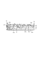
- FIG. 4 shows the internal structure of the LED lighting device of FIG. 3 as a cross-sectional view.
- a stand illumination 170 for indoor illumination and a light emitting surface 180 is formed on the lower surface of the main body of the stand illumination 170 supported by an arm as shown in the figure.
- the light emitting surface 180 is configured by exposing a light guide plate (20), which will be described later, to the lower surface of the main body of the stand illumination 170.
- the LED light source module 150 is configured so as to be slidable and detachable at an appropriate position of the main body of the stand illumination 170 as shown in FIG. 3 (rear end portion supported by an arm in the illustrated example).
- the LED light source module 150 is configured in a rectangular parallelepiped shape as shown in FIG. 1 on the front side and in FIG. 2 on the back side. 1 and 2 show the LED light source module 150 mounted in an inverted state in the example of FIG. 3 in an upright state.
- a plurality (four in the illustrated example) of LEDs 110 are arranged on the front side of the LED light source module 150. These LEDs 110 are mounted on a substrate 120 disposed under the LED light source module 150. A driving circuit (for example, a current limiting resistor: not shown) of the LED 110 is incorporated on the substrate 120 as necessary.
- the upper part of the substrate 120 is configured as a heat conductor 140 formed so as to form a substantially U-shaped portion on the upper surface of the LED light source module 150.
- Chamfered portions for facilitating slide attachment / detachment with respect to the stand lighting 170 are formed at the upper left and right ends of the heat conductor 140.
- the heat conductor 140 can be made of heat-resistant plastic or metal. However, since the contact electrodes 131 and 132 are disposed at the left and right corners of the heat conductor 140, respectively, when using a material such as metal for the heat conductor 140, the left and right contact electrodes 131 and 132 are not short-circuited. It is necessary to dispose an insulating material or the like between the heat conductor 140 and the contact electrodes 131 and 132.
- the back surface of the LED light source module 150 is a back plate made of plastic or the like, and a guide groove 160 is provided in this portion (in the example shown, two lines). Note that the portion of the back plate provided with the guide groove 160 may be configured integrally with the heat conductor 140.
- a storage opening configured to have an inner dimension slightly larger than the outer shape of the LED light source module 150 as a storage portion for storing the LED light source module 150 shown in FIGS.
- Protruding lines that are provided and engage with the guide grooves 160 are disposed therein.
- the internal structure of the storage opening of the stand illumination 170 is provided so that the position of each LED 110 is aligned with the position where each light guide plate described later can be efficiently irradiated with light when the LED light source module 150 is slid.
- an electrode that contacts the contact electrodes 131 and 132 of the LED light source module 150 is provided inside the accommodation opening of the stand illumination 170 to supply power for LED lighting.
- a heat conductive elastic body is used as the heat conductor portion 140 of the LED light source module 150 so that the heat accumulated in the heat conductor 140 is easily transmitted to the main body of the stand lighting 170. It may be configured so as to be in contact with the main body of the lighting 170 without a gap, and heat may be transmitted to the main body of the stand lighting 170. Alternatively, such an elastic body may be provided inside the accommodation opening of the stand lighting 170. Further, a heat radiating means such as a heat radiating plate, a heat sink, and a heat radiating hole for radiating heat transferred from the heat conductor 140 may be provided on the main body side of the stand lighting 170. By providing such a heat dissipation structure, heat can be efficiently radiated from the LED light source module 150, and the life of the LED 110 can be extended.
- FIG. 4 shows an example of the internal structure of the stand illumination 170, particularly the arrangement of the light guide plate.
- the structure of FIG. 4 is obtained by laminating three light guide plates 20, 21, and 22. Among these, the light guide plate 20 is exposed as the light emitting surface 180 of FIG.
- the light guide plates 20, 21, and 22 are made of a highly light-transmitting material, for example, a transparent acrylic resin, and a plurality of concave fine-shaped reflecting portions 20e, 20e,. Arranged to be scattered.
- the light guide plates 20, 21, and 22 are formed as light guide plates in which fine reflection portions 20e are arranged in a grid pattern, for example, by injection molding using a mold.
- the reflecting portion 20e has, for example, a thickness of the light guide plate 20 of 1 mm (dot density of about 15000 pieces / cm 2 ), a larger diameter d1 of about 55 ⁇ m, a smaller diameter d2 of about 10 ⁇ m, and a height d3 of about It is formed in a truncated cone shape of 30 ⁇ m (FIG. 4 is shown in an enlarged state for easy understanding).
- the reflecting portions 20e may be uniformly arranged on one surface of the light guide plates 20 to 22.
- the number per unit area gradually increases as the distance from the incident portion (left side in the drawing) of the light guide plate is increased. You may arrange in. As shown in FIG. 4, when a plurality of light guide plates (three in the example of FIG. 4) are stacked, the number of times of light reflection increases, and light is efficiently emitted from the light exit surface.
- reference numeral 10 corresponds to the LED light source module 150 in FIGS. 1 to 3
- reference numeral 13 corresponds to a substantial light emitting portion (LED 110).
- the light emitting portion 13 is one end of the light guide plates 20 to 22.
- the above-described slide mechanism is configured to match the above.
- the overlapping thickness of the light guide plates 20 to 22 is slightly larger than the light emitting portion 13 of the LED, and the center of the overlapped light guide plate coincides with the center of the LED light emitting portion (the center of the LED 110). Ideally, they are arranged as follows.
- the light that has reached from the light guide plates 20 to 22 or between the light guide plates 20 to 22 is again (again) in the direction of the light guide plates 20 to 22.
- a reflection plate 12 for reflection is disposed.
- the structure using a plurality of light guide plates as described above enables efficient and bright LED illumination.
- the position of the LED 110 of the LED light source module 150 is aligned with the light introduction portion of the light guide plates 20 to 22 by the positioning mechanism using the guide groove 160 of the LED light source module 150. Is always placed in an ideally stable position, that is, the center of the side surface of the overlapped light guide plate coincides with the center of the LED light emitting surface, so that the amount of light from the light emitting surface of the light guide plate 20 increases.
- the illumination light quantity as designed can be obtained, and the problem that the light quantity varies from product to product can be avoided.
- the LED light source module 150 can be easily attached to and detached from the LED lighting device via a slide-type attaching / detaching mechanism.
- the LED light source module 150 needs to be replaced due to deterioration of the LED or in the event of a failure, the LED light source module 150 is plugged in. Therefore, only the portion of the LED light source module 150 can be easily replaced.
- the LED light source module 150 containing different LEDs is prepared in consideration of the case where it is desired to change the specification of the LED illumination, for example, the color temperature of the LED, etc.
- the LED light source module formed as a plug-in module The specification of the LED illumination can be easily changed by simply replacing 150 parts. Therefore, once the product specifications as in the present embodiment are adopted, it is possible to increase the product variations without requiring a large manufacturing cost simply by preparing the LED light source module 150. Value can be increased.
- the LED light source module 150 is provided with the guide groove 160, and the protrusion or the like so as to engage with the guide groove 160 in the housing portion of the main body of the LED illumination device (stand illumination 170).
- the LED light source module 150 and an engaging means for engaging with each other in the housing portion of the LED lighting apparatus main body may be provided.
- the specific configuration of these engaging means is that the LED light source is located on the end face of the light guide plate.
- the groove and the ridge are not limited to the above as long as they can be positioned so as to be aligned according to the positional relationship.
- the concave / convex relationship between the groove and the protrusion of the housing portion of the LED light source module 150 and the main body of the LED illumination device (stand illumination 170) may be reversed.
- the configuration of the LED illumination device using the LED light source module according to the present invention is also applied to products such as LCD backlights, slide photographs, and light boxes for transparency observation. can do.
Landscapes
- Engineering & Computer Science (AREA)
- Physics & Mathematics (AREA)
- General Engineering & Computer Science (AREA)
- Optics & Photonics (AREA)
- General Physics & Mathematics (AREA)
- Microelectronics & Electronic Packaging (AREA)
- Planar Illumination Modules (AREA)
- Arrangement Of Elements, Cooling, Sealing, Or The Like Of Lighting Devices (AREA)
- Non-Portable Lighting Devices Or Systems Thereof (AREA)
- Fastening Of Light Sources Or Lamp Holders (AREA)
Abstract
複数枚重ねて配置した導光板の端面からLEDを光源とする照射光を照射して前記導光板の発光面から発光させるLED照明装置170に、複数のLED光源を収容し、前記LED照明装置本体の収容部に対してスライド着脱可能なLED光源モジュール150を設ける。LED光源モジュール150には、LED照明装置本体からLED光源を点灯させるための電流の供給を受ける電極131、132を設けるとともに、LED照明装置本体に対してLED光源の熱を放熱するための熱伝導体140を設ける。また、LED光源モジュール150とLED照明装置本体は係合手段の係合によってLED光源が照明装置本体内の所定位置に正しく位置決めされる。
Description
本発明は、複数枚重ねた導光板の側面から、LEDを光源とする照射光を照射して前記導光板の発光面から発光させるLED照明装置に関する。
従来より、導光板(あるいは拡散板)およびLED光源を使用した照明装置が提案されている。このような装置には、作業者の手元を照明するための室内用の照明装置のほか、LCDバックライトや、スライド写真、トランスパレンシー観察用のライトボックスのような製品なども含まれる。
LED光源とともに導光板を使用する最大の特徴は、発光面に対して光源のLEDの光を導光板の側面から入射することが可能である点で、これにより製品の薄型化が可能となる。また、その他の特徴として、導光板を重ねることで導光板に設けられた微細加工部の分布密度が見かけ上増すことになり、単数枚の導光板と比較して発光面の光量が増大するという特徴がある(たとえば下記の特許文献1、図4)。
また、LED光源は定格寿命が長く、たとえば典型的なLED電球の製品は、定格寿命が20000時間前後に及ぶものがあり、一般に白熱電球よりも長寿命である、という特徴がある。
しかし、いくら長寿命であっても使用環境によってはLEDが劣化しやすい状況も考えられる(例えば高温環境下など)ため、またLED照明装置は白熱電球照明に比べて高価格であるため、LED光源のみを交換可能とした照明装置も開示されている(たとえば下記の特許文献2)。
上記特許文献2に記載されるようにLED光源を交換可能とする場合、単に個々のLED光源を交換できるようにしただけでは、一般にLED光源には小さいものが多く、また白熱球のような着脱構造を持たないものが多いし、また、LED照明装置の場合、多数のLED光源が用いられるから、交換作業が困難で面倒なものになりがちである。そこで、複数のLED光源をユニット化して着脱式のLED光源モジュールとして構成するような構造が考えられる。
このような着脱式のLED光源モジュールを用いる構造では次のような技術課題が予想される。
まず、導光板を用いたLED照明装置では、複数枚重ねた導光板の側面からLEDを光源とする照射光を照射して導光板の発光面から発光させるものがある。このような構成においては、発光面からの発光量は複数枚重ねた導光板の側面とLEDの位置関係に大きく影響される。LED光が導光板側面から漏れていると、その漏れた光は他に反射する要素が無い限り発光面まで届かなくなってしまう。したがって、交換可能なLED光源モジュールを用いた照明装置を製造する際には、複数枚重ねた導光板とLEDの位置を正しく設定できなければならない。
また、通常可視光の照明装置に用いられるLEDは赤外光を発しないため、蛍光灯や白熱灯が赤外光で放熱しているのと比較して、発生した熱が光によって放出されない分、蛍光灯や白熱灯よりも発光部に熱がこもり易く、このため発光部に放熱手段(熱伝導部材)を設ける必要がある。LED照明装置にLED光源モジュールを用いる場合には、このような放熱手段が体裁よく組み込まれていなければならない。
また、従来のLED照明はその長寿命の性質からメンテナンスフリーであり、小型組み込み式が可能であるため部品交換を考慮されないものが多い。しかし産業用途においては定格寿命が有限である以上交換は必須であり、また、新品であってもLEDが不良品だったり、予期せぬ衝撃などで故障した場合などが想定されるため、簡単な部品交換で修理対応できるようにする必要がある。また、電気的仕様が同じであれば、メーカにかかわらず同等の電気回路構成で異なる仕様のLED、たとえば、色温度の異なるLEDなどを使用できることも多く、ユーザが1つの機器でLED照明の仕様を簡単に変更できることはメリットである。したがって、LED照明装置のLED光源モジュールは、着脱が極めて容易に行なえなければならない。
本発明の課題は、以上に鑑み、LED光源の交換が容易で簡単安価に構成可能なLED光源モジュールを用いたLED照明装置を提供することにある。
以上の課題を解決するため、本発明においては、複数枚重ねて配置した導光板の端面からLEDを光源とする照射光を照射して前記導光板の発光面から発光させるLED照明装置であって、LED照明装置本体、および、複数のLED光源を収容し、前記LED照明装置本体の収容部に対してスライド着脱可能なLED光源モジュールから成る構成を採用した。
あるいはさらに、前記LED光源モジュールが、前記LED照明装置本体から前記LED光源を点灯させるための電流の供給を受ける電極を有する構成を採用した。
あるいはさらに、前記LED光源モジュールが、前記LED照明装置本体に対して前記LED光源の熱を放熱するための熱伝導体を含む構成を採用した。
あるいはさらに、前記LED光源モジュールが、前記LED照明装置本体の収容部に設けた係合手段と互いに係合する係合手段を有し、これら係合手段の両者の係合によって前記LED光源が前記導光板の端面に所期の位置関係で整合するよう位置決めされる構成を採用した。
上記構成によれば、複数枚重ねて配置した導光板の端面からLEDを光源とする照射光を照射して前記導光板の発光面から発光させる方式のLED照明装置を、LED照明装置本体、および、複数のLED光源を収容し、前記LED照明装置本体の収容部に対してスライド着脱可能なLED光源モジュールから成る構成とすることにより、LED光源の交換が容易で簡単安価に構成可能なLED照明装置を提供することができる。
また、プラグイン方式の前記LED光源モジュールに前記LED照明装置本体から前記LED光源を点灯させるための電流の供給を受ける電極を設けることにより配線作業を必要とせずにLED光源モジュールに容易に着脱することができる。
また、前記LED光源モジュールが、前記LED照明装置本体に対して前記LED光源の熱を放熱するための熱伝導体を含む構成とすることにより、LED光源の熱を放熱することができ、LED光源の寿命を延長することができ、耐久性に優れたLED照明装置を提供することができる。
また、前記LED光源モジュールと前記LED照明装置本体の収容部に互いに係合する係合手段を有し、これら係合手段の両者の係合によってLED光源を前記導光板の端面に所期の位置関係で整合するよう位置決めすることができるため、導光板の発光面からの光量が増大し、設計通りの照明光量を得ることができ、また、製品ごとに光量がばらつくなどの問題を回避することができる。
以下、図面に示す実施例に基づいて本発明を説明する。
図3に本発明を採用したLED照明装置の全体構造を、また、図1および図2に図4のLED照明装置に用いられる着脱式のLED光源モジュールの構造をそれぞれ斜視図として示す。また、図4は図3のLED照明装置の内部構造を断面図として示したものである。
図3のLED照明装置は、室内照明用のスタンド照明170として構成されており、図示のようにアームで支持されたスタンド照明170の本体部下面には発光面180が形成されている。この発光面180は、後述の導光板(20)をスタンド照明170の本体部下面に露出させて構成したものである。
LED光源モジュール150は、図3のようにスタンド照明170の本体の適当な位置(図示の例ではアームで支持された後端部)にスライド着脱できるように構成する。
LED光源モジュール150は図1に前面側を、また図2に背面側を示すように直方体形状に構成する。図1および図2は、図3の例では倒立状態で装着されるLED光源モジュール150を正立状態で示したものである。
図1および図2に示すようにLED光源モジュール150の前面側には、複数(図示の例では4個)のLED110が配列される。これらLED110はLED光源モジュール150の下部に配置した基板120上に実装される。基板120上には必要に応じてLED110の駆動回路(たとえば電流制限用の抵抗など:不図示)が組み込まれる。
基板120の上部は、LED光源モジュール150の上面のほぼコの字型の部分を形成するよう形成された熱伝導体140として構成されている。熱伝導体140の左右両端の上部は、スタンド照明170に対するスライド着脱を容易にするための面取り部が形成されている。熱伝導体140は耐熱性のあるプラスチックや、あるいは金属などから構成することができる。ただし、熱伝導体140の左右両端の角部にそれぞれ接点電極131、132を配置するため、熱伝導体140に金属などの材質を用いる場合には左右の接点電極131、132が短絡しないように熱伝導体140と接点電極131、132との間に絶縁材料などを配置する必要がある。
図2に示すように、LED光源モジュール150の背面はプラスチックなどから構成された背面板となっており、この部分にはガイド溝160を設けてある(図示の例では2条)。なお、ガイド溝160を設けた背面板の部分も上記の熱伝導体140と一体に構成するようにしてもよい。
スタンド照明170側の装着部としては、図1および図2に示したLED光源モジュール150を収容するための収容部としてLED光源モジュール150の外形よりもわずかに大きな内寸で構成された収容口を設け、その内部には上記のガイド溝160に係合する凸条を配置する。このようなスタンド照明170の収容口の内部構造は、LED光源モジュール150をスライド装着した場合、各LED110の位置が後述の各導光板に効率よく光を照射できる位置に整合するように設けておく。また、スタンド照明170の収容口内部には、LED光源モジュール150の接点電極131、132と接触する電極を設け、LED点灯用の電源を供給するのはいうまでもない。
なお、熱伝導体140に関しては、熱伝導体140に蓄積された熱がスタンド照明170本体に伝わりやすいよう、LED光源モジュール150の熱伝導体部140として熱伝導性のある弾性体を用い、スタンド照明170の本体との間に隙間なく接するよう構成し、スタンド照明170の本体に熱が伝わるようにしてもよい。あるいはこのような弾性体はスタンド照明170の収容口の内部に設けてもよい。また、熱伝導体部140から伝わった熱を放熱するための放熱板、ヒートシンク、放熱孔などの放熱手段をスタンド照明170の本体側に設けるようにしてもよい。このような放熱構造を設けることにより、効率よくLED光源モジュール150から放熱することができ、LED110の寿命を延長することができる。
図4は、スタンド照明170の内部構造の一例、特に導光板の配置を示したものである。図4の構造は、3枚の導光板20、21、22を積層したものである。このうち、導光板20は図3の発光面180としてスタンド照明170本体の下面に露出させる。
導光板20、21、22は、光透過性の高い材料、たとえば、透明なアクリル樹脂から形成され、その出射面の反対側の面には、凹状の微細形状の反射部20e、20e…が複数個点在するように配置される。
導光板20、21、22は、たとえば金型を用いて射出成形により、微細な反射部20eが碁盤の目状に配列された導光板として形成される。反射部20eは、たとえば導光板20の厚さを1mm(ドット密度は約15000個/cm2)として、大きい方の直径d1が約55μm、小さい方の直径d2が約10μm、高さd3が約30μmの円錐台形状に形成される(図4は、理解を容易にするため拡大した状態で示してある)。
また、反射部20eは、導光板20~22の1面に均一に配置してもよいが、たとえば導光板の入射部(図の左側)から離れるに従って単位面積あたりの個数が徐々に増大するように配置してもよい。図4に示すように、導光板を複数枚(図4の例では3枚)積層配置したほうが、光の反射回数が増え、光出射面から効率よく光が出射される。
図4において符号10は図1~図3におけるLED光源モジュール150に相当し、また、符号13はその実体的な発光部位(LED110)に相当し、この発光部13が導光板20~22の一端に整合するよう、上記のスライド機構が構成される。なお、図示のように、導光板20~22の重ねあわせの厚みはLEDの発光部位13よりも若干大きめで、重ね合わせた導光板の中心がLED発光部位の中心(LED110の中心)と一致するように配置されるのが理想的である。導光板20~22のLED光源モジュール150とは反対側の他端には、導光板20~22、あるいは導光板20~22の間などから到達した光を導光板20~22方向に再度(再々度…)反射させるための反射板12が配置される。
以上のような複数の導光板を用いた構造により、効率よく明るいLED照明が可能となる。また、LED光源モジュール150のガイド溝160を用いた位置決め機構によって、LED光源モジュール150のLED110の位置が導光板20~22の光導入部に整合するため、特に、ガイド溝160によってLED光源モジュール150が常に理想的に安定した位置、つまり重ね合わせた導光板の側面の中心がLED発光面の中心と一致する位置に配置されるようになるため、導光板20の発光面からの光量が増大し、設計通りの照明光量を得ることができ、また、製品ごとに光量がばらつくなどの問題を回避することができる。
また、LED光源モジュール150は、スライド式の着脱機構を介して容易にLED照明装置に着脱でき、LEDの劣化などによって交換が必要となった時や、故障時には、LED光源モジュール150がプラグインモジュール化されているので、LED光源モジュール150の部分のみを簡単に交換することができる。また、LED照明の仕様を変更したい、たとえばLEDの色温度を変更したい場合などを考慮して、異なるLEDを収容したLED光源モジュール150を用意しておけば、プラグインモジュール化されたLED光源モジュール150の部分を交換するだけで、容易にLED照明の仕様を変更することができる。したがって、一旦、本実施例のような製品仕様を採用しておけば、LED光源モジュール150を用意するだけで大きな製造コストを必要とせずに製品のバリエーションを増やすことができ、製品ラインアップの付加価値を高めることができる。
なお、以上では、LED光源モジュール150がガイド溝160を、また、このガイド溝160と係合するよう突条などをLED照明装置本体(スタンド照明170)本体の収容部に設けることとしたが、要はLED光源モジュール150と、LED照明装置本体の収容部に互いに係合する係合手段を設ければよく、これら係合手段の具体的な構成は前記LED光源を前記導光板の端面に所期の位置関係で整合するよう位置決めできるものであれば上記の溝や突条に限定されるものではない。たとえば、LED光源モジュール150と、LED照明装置本体(スタンド照明170)本体の収容部の溝や突条の凹凸関係は上記と逆であってもよい。
本発明によるLED光源モジュールを用いたLED照明装置の構成は、上述のようなスタンド照明装置以外にも、LCDバックライトや、スライド写真、トランスパレンシー観察用のライトボックスのような製品にも実施することができる。
12 反射板
20~22 導光板
110 LED
120 基板
131、132 接点電極
140 熱伝導体
150 LED光源モジュール
160 ガイド溝
170 スタンド照明
180 発光面
20~22 導光板
110 LED
120 基板
131、132 接点電極
140 熱伝導体
150 LED光源モジュール
160 ガイド溝
170 スタンド照明
180 発光面
Claims (4)
- 複数枚重ねて配置した導光板の端面からLEDを光源とする照射光を照射して前記導光板の発光面から発光させるLED照明装置であって、
LED照明装置本体、および、複数のLED光源を収容し、前記LED照明装置本体の収容部に対してスライド着脱可能なLED光源モジュールから成ることを特徴とするLED照明装置。 - 前記LED光源モジュールが、前記LED照明装置本体から前記LED光源を点灯させるための電流の供給を受ける電極を有することを特徴とする請求項1に記載のLED照明装置。
- 前記LED光源モジュールが、前記LED照明装置本体に対して前記LED光源の熱を放熱するための熱伝導体を含むことを特徴とする請求項1に記載のLED照明装置。
- 前記LED光源モジュールが、前記LED照明装置本体の収容部に設けた係合手段と互いに係合する係合手段を有し、これら係合手段の両者の係合によって前記LED光源が前記導光板の端面に所期の位置関係で整合するよう位置決めされることを特徴とする請求項1に記載のLED照明装置。
Applications Claiming Priority (2)
| Application Number | Priority Date | Filing Date | Title |
|---|---|---|---|
| JP2009-110278 | 2009-04-30 | ||
| JP2009110278A JP2010262742A (ja) | 2009-04-30 | 2009-04-30 | Led照明装置 |
Publications (1)
| Publication Number | Publication Date |
|---|---|
| WO2010125927A1 true WO2010125927A1 (ja) | 2010-11-04 |
Family
ID=43032080
Family Applications (1)
| Application Number | Title | Priority Date | Filing Date |
|---|---|---|---|
| PCT/JP2010/056767 Ceased WO2010125927A1 (ja) | 2009-04-30 | 2010-04-15 | Led照明装置 |
Country Status (2)
| Country | Link |
|---|---|
| JP (1) | JP2010262742A (ja) |
| WO (1) | WO2010125927A1 (ja) |
Cited By (1)
| Publication number | Priority date | Publication date | Assignee | Title |
|---|---|---|---|---|
| CN104848097A (zh) * | 2015-05-28 | 2015-08-19 | 罗佑飞 | 一种led面板灯 |
Families Citing this family (5)
| Publication number | Priority date | Publication date | Assignee | Title |
|---|---|---|---|---|
| JP5830674B2 (ja) * | 2011-01-24 | 2015-12-09 | パナソニックIpマネジメント株式会社 | Ledユニットおよび照明器具 |
| JP5328860B2 (ja) * | 2011-09-12 | 2013-10-30 | 株式会社フジクラ | 発光装置 |
| WO2014065304A1 (ja) * | 2012-10-26 | 2014-05-01 | 三菱レイヨン株式会社 | 導光体、導光体の製造方法、光シャッター及び面光源装置 |
| JP6471586B2 (ja) * | 2015-03-31 | 2019-02-20 | 東芝ライテック株式会社 | 照射体及び照射装置 |
| JP6693581B2 (ja) * | 2019-01-23 | 2020-05-13 | 東芝ライテック株式会社 | 照射体及び照射装置 |
Citations (5)
| Publication number | Priority date | Publication date | Assignee | Title |
|---|---|---|---|---|
| JPH0451708U (ja) * | 1990-09-05 | 1992-04-30 | ||
| JP2005235778A (ja) * | 2001-08-09 | 2005-09-02 | Matsushita Electric Ind Co Ltd | Led照明装置およびカード型led照明光源 |
| JP2007059285A (ja) * | 2005-08-26 | 2007-03-08 | Matsushita Electric Works Ltd | 照明器具 |
| WO2008057680A2 (en) * | 2006-11-03 | 2008-05-15 | Apple Inc. | Display system |
| JP2008112610A (ja) * | 2006-10-30 | 2008-05-15 | Jikco Ltd | 照明装置及び発光標識システム |
-
2009
- 2009-04-30 JP JP2009110278A patent/JP2010262742A/ja active Pending
-
2010
- 2010-04-15 WO PCT/JP2010/056767 patent/WO2010125927A1/ja not_active Ceased
Patent Citations (5)
| Publication number | Priority date | Publication date | Assignee | Title |
|---|---|---|---|---|
| JPH0451708U (ja) * | 1990-09-05 | 1992-04-30 | ||
| JP2005235778A (ja) * | 2001-08-09 | 2005-09-02 | Matsushita Electric Ind Co Ltd | Led照明装置およびカード型led照明光源 |
| JP2007059285A (ja) * | 2005-08-26 | 2007-03-08 | Matsushita Electric Works Ltd | 照明器具 |
| JP2008112610A (ja) * | 2006-10-30 | 2008-05-15 | Jikco Ltd | 照明装置及び発光標識システム |
| WO2008057680A2 (en) * | 2006-11-03 | 2008-05-15 | Apple Inc. | Display system |
Cited By (2)
| Publication number | Priority date | Publication date | Assignee | Title |
|---|---|---|---|---|
| CN104848097A (zh) * | 2015-05-28 | 2015-08-19 | 罗佑飞 | 一种led面板灯 |
| CN104848097B (zh) * | 2015-05-28 | 2017-11-28 | 罗佑飞 | 一种led面板灯 |
Also Published As
| Publication number | Publication date |
|---|---|
| JP2010262742A (ja) | 2010-11-18 |
Similar Documents
| Publication | Publication Date | Title |
|---|---|---|
| KR101253199B1 (ko) | 조명 장치 | |
| WO2010125927A1 (ja) | Led照明装置 | |
| US9551478B2 (en) | Lighting device | |
| JP2014186838A (ja) | ランプ装置および照明装置 | |
| JP2014154230A (ja) | ランプ装置、発光装置および照明装置 | |
| JPWO2015133045A1 (ja) | 照明器具 | |
| JP4602477B1 (ja) | 照明装置 | |
| JP2012146425A (ja) | Led照明具 | |
| JP5270433B2 (ja) | 発光装置および看板用の照明装置 | |
| JP3163443U (ja) | Led式照明装置 | |
| JP4969345B2 (ja) | 表示装置及び誘導灯 | |
| JP5956396B2 (ja) | 照明器具 | |
| TWI580888B (zh) | A support for a semiconductor light emitting element, a semiconductor light emitting element module, and an illuminator And a method for manufacturing a support for a semiconductor light-emitting element | |
| JP2013065442A (ja) | 照明装置 | |
| JP5882525B2 (ja) | 半導体発光素子用ホルダ、及び、半導体発光素子モジュール | |
| CN101881383B (zh) | 菲涅尔式发光二极管灯条式灯具 | |
| JP6110528B2 (ja) | 半導体発光素子用ホルダ、及び、半導体発光素子モジュール | |
| JP2012227057A (ja) | ランプユニット及びランプソケット | |
| KR20130074991A (ko) | 발광 모듈 | |
| JP2016195123A (ja) | 光学素子及び照明器具 | |
| JP5894310B2 (ja) | 半導体発光素子用ホルダの製造方法 | |
| KR101272830B1 (ko) | 리플렉터를 구비한 조명장치 및 조립방법 | |
| JP5811960B2 (ja) | 発光モジュール | |
| TW201411036A (zh) | Led燈具之組卸結構 | |
| JP2016046191A (ja) | ランプ |
Legal Events
| Date | Code | Title | Description |
|---|---|---|---|
| 121 | Ep: the epo has been informed by wipo that ep was designated in this application |
Ref document number: 10769626 Country of ref document: EP Kind code of ref document: A1 |
|
| NENP | Non-entry into the national phase |
Ref country code: DE |
|
| 122 | Ep: pct application non-entry in european phase |
Ref document number: 10769626 Country of ref document: EP Kind code of ref document: A1 |