WO2010123233A2 - 액체보관용기용 디스펜서 - Google Patents
액체보관용기용 디스펜서 Download PDFInfo
- Publication number
- WO2010123233A2 WO2010123233A2 PCT/KR2010/002412 KR2010002412W WO2010123233A2 WO 2010123233 A2 WO2010123233 A2 WO 2010123233A2 KR 2010002412 W KR2010002412 W KR 2010002412W WO 2010123233 A2 WO2010123233 A2 WO 2010123233A2
- Authority
- WO
- WIPO (PCT)
- Prior art keywords
- dispenser
- container
- liquid
- stopper
- plate
- Prior art date
- Legal status (The legal status is an assumption and is not a legal conclusion. Google has not performed a legal analysis and makes no representation as to the accuracy of the status listed.)
- Ceased
Links
Images


Classifications
-
- B—PERFORMING OPERATIONS; TRANSPORTING
- B05—SPRAYING OR ATOMISING IN GENERAL; APPLYING FLUENT MATERIALS TO SURFACES, IN GENERAL
- B05B—SPRAYING APPARATUS; ATOMISING APPARATUS; NOZZLES
- B05B11/00—Single-unit hand-held apparatus in which flow of contents is produced by the muscular force of the operator at the moment of use
- B05B11/0005—Components or details
- B05B11/0062—Outlet valves actuated by the pressure of the fluid to be sprayed
- B05B11/007—Outlet valves actuated by the pressure of the fluid to be sprayed being opened by deformation of a sealing element made of resiliently deformable material, e.g. flaps, skirts, duck-bill valves
-
- B—PERFORMING OPERATIONS; TRANSPORTING
- B05—SPRAYING OR ATOMISING IN GENERAL; APPLYING FLUENT MATERIALS TO SURFACES, IN GENERAL
- B05B—SPRAYING APPARATUS; ATOMISING APPARATUS; NOZZLES
- B05B11/00—Single-unit hand-held apparatus in which flow of contents is produced by the muscular force of the operator at the moment of use
- B05B11/01—Single-unit hand-held apparatus in which flow of contents is produced by the muscular force of the operator at the moment of use characterised by the means producing the flow
- B05B11/10—Pump arrangements for transferring the contents from the container to a pump chamber by a sucking effect and forcing the contents out through the dispensing nozzle
- B05B11/1042—Components or details
- B05B11/1052—Actuation means
-
- B—PERFORMING OPERATIONS; TRANSPORTING
- B65—CONVEYING; PACKING; STORING; HANDLING THIN OR FILAMENTARY MATERIAL
- B65D—CONTAINERS FOR STORAGE OR TRANSPORT OF ARTICLES OR MATERIALS, e.g. BAGS, BARRELS, BOTTLES, BOXES, CANS, CARTONS, CRATES, DRUMS, JARS, TANKS, HOPPERS, FORWARDING CONTAINERS; ACCESSORIES, CLOSURES, OR FITTINGS THEREFOR; PACKAGING ELEMENTS; PACKAGES
- B65D47/00—Closures with filling and discharging, or with discharging, devices
- B65D47/04—Closures with discharging devices other than pumps
- B65D47/06—Closures with discharging devices other than pumps with pouring spouts or tubes; with discharge nozzles or passages
-
- B—PERFORMING OPERATIONS; TRANSPORTING
- B65—CONVEYING; PACKING; STORING; HANDLING THIN OR FILAMENTARY MATERIAL
- B65D—CONTAINERS FOR STORAGE OR TRANSPORT OF ARTICLES OR MATERIALS, e.g. BAGS, BARRELS, BOTTLES, BOXES, CANS, CARTONS, CRATES, DRUMS, JARS, TANKS, HOPPERS, FORWARDING CONTAINERS; ACCESSORIES, CLOSURES, OR FITTINGS THEREFOR; PACKAGING ELEMENTS; PACKAGES
- B65D47/00—Closures with filling and discharging, or with discharging, devices
- B65D47/04—Closures with discharging devices other than pumps
- B65D47/32—Closures with discharging devices other than pumps with means for venting
-
- B—PERFORMING OPERATIONS; TRANSPORTING
- B65—CONVEYING; PACKING; STORING; HANDLING THIN OR FILAMENTARY MATERIAL
- B65D—CONTAINERS FOR STORAGE OR TRANSPORT OF ARTICLES OR MATERIALS, e.g. BAGS, BARRELS, BOTTLES, BOXES, CANS, CARTONS, CRATES, DRUMS, JARS, TANKS, HOPPERS, FORWARDING CONTAINERS; ACCESSORIES, CLOSURES, OR FITTINGS THEREFOR; PACKAGING ELEMENTS; PACKAGES
- B65D83/00—Containers or packages with special means for dispensing contents
-
- B—PERFORMING OPERATIONS; TRANSPORTING
- B05—SPRAYING OR ATOMISING IN GENERAL; APPLYING FLUENT MATERIALS TO SURFACES, IN GENERAL
- B05B—SPRAYING APPARATUS; ATOMISING APPARATUS; NOZZLES
- B05B11/00—Single-unit hand-held apparatus in which flow of contents is produced by the muscular force of the operator at the moment of use
- B05B11/01—Single-unit hand-held apparatus in which flow of contents is produced by the muscular force of the operator at the moment of use characterised by the means producing the flow
- B05B11/10—Pump arrangements for transferring the contents from the container to a pump chamber by a sucking effect and forcing the contents out through the dispensing nozzle
- B05B11/1001—Piston pumps
Definitions
- the present invention relates to a dispenser for a liquid storage container, and more particularly, even when the container is tilted or flipped, the contents stored inside, for example, a liquid, such as a detergent, a chemical liquid or a cosmetic liquid, are externally discharged through the dispensing hole of the dispenser.
- a liquid such as a detergent, a chemical liquid or a cosmetic liquid
- the present invention relates to a dispenser for a liquid storage container that does not leak into a container.
- the dispenser is a device for discharging the contents stored in the container, for example, a liquid object such as detergent, chemical liquid or cosmetic liquid by external force.
- a dispenser is applied to a container in which a liquid is stored is disclosed in "Dispenser cover" of Japanese Utility Model Registration No. 33101097.
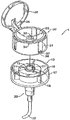
- FIG. 5 is an exploded perspective view showing a conventional dispenser cover 1
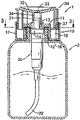
- FIG. 6 is a cross-sectional view thereof.
- the conventional dispenser cover 1 has a cap 10, a suction part 20, and a head 30.
- the cap 10 has a mounting portion 11, a mounting recess 12 is formed at the bottom of the mounting portion 11, and a through hole 13 is formed at the center of the upper surface.
- the through hole 13 is provided with a connecting portion 14 facing downward to the mounting recess 12, and a screw thread is formed on the inner surface of the mounting recess 12 so as to be installed in the opening of the container 2. .
- the suction part 20 is connected with the connection part 14 of the cap 10, and has the discharge part 21 which penetrates the through-hole 13, and the guide pipe 22 extended into the container 2. As shown in FIG.
- the head 30 has a concave convex part 31 which is installed on the mounting part 11 of the cap 10 on the bottom surface, and an accommodating concave part 32 having at least one liquid discharge hole 33 is formed on the upper surface of the head 30. Is formed.
- the head 30 has a connection pipe 34 connected to the liquid discharge part 21 at the lower part of the liquid discharge hole 33, and a lid 35 covering the accommodating recess 32 is provided at one side of the elastic plate 36. It is installed via).
- the contents having the above-described configuration are liquids having a low viscosity, the contents flow out to the outside through the exit hole 33 when the container is inclined or turned upside down, thereby contaminating the dispenser cover 1 or the container 2. .
- the user may carry the container 2 in a bag or the like to leak the contents and contaminate other belongings or bags. There was.
- the present invention has been made to solve the above-mentioned problems of the prior art, the problem to be solved by the present invention by selectively blocking the dispensing hole of the dispenser with the contents in the container, even when the container is inclined or upside down the contents of the liquid ejection hole It is to provide a dispenser for a liquid storage container does not flow through the outside.
- the present invention includes a cap detachably installed in the container, a suction unit for sucking the contents stored in the cap, the operation unit for operating the suction unit while pressed by an external force
- the operation part has a pressing plate formed at the center of a plurality of liquid discharge holes connected to the liquid discharge part of the suction portion, and the plurality of liquid discharge holes are blocked by a leak stopper which is opened and closed according to the discharge pressure of the contents.
- the cap is formed on the upper surface of the mounting recess is formed in the through hole in the center, the lid covering the mounting recess on one side is provided via the elastic plate, characterized in that the bottom is provided with an installation portion coupled to the container
- the suction portion is provided with a mounting plate that is tightly fitted inside the installation portion of the cap, a hollow stem column facing downward in the center of the installation plate, the induction extending through the through hole and the inside of the container
- the operation portion is provided with a fitting boss leading to a plurality of liquid discharge holes on the bottom surface of the pressing plate, the fitting boss is characterized in that the fitting portion is tightly fitted into the discharge portion.
- the pressing plate is formed with a through hole in the center, and the installation ring is provided in the through hole to be fixed through a plurality of legs, the stopper stopper is fitted into the stopper plate and the installation ring to block the through hole of the pressing plate.
- the stopper plate is inclined slightly from the center to the rim so as to have a convex shape as a whole, the rim is another feature that the inclined portion is cut inclined to the bottom surface.
- the inclined portion is another feature that starts from about 1/2 of the total thickness of the stopper plate.
- the fitting protrusion has a protrusion body that is fitted to the mounting ring and an extension extending outward from the protrusion body, the protrusion body is characterized in that the outer diameter is larger than the inner diameter of the mounting ring, the extension is smaller than the outer diameter of the mounting ring, the extension The part is characterized in that the bottom surface is inclined to be clipped to facilitate the fitting ring.
- the stopper plate is characterized in that the diameter of 2.5-3.0 times the diameter of the fitting protrusion.
- the leak stopper is excellent in workability, abrasion resistance, tear resistance, bending resistance, and maintains excellent physical properties even when a large amount of filler is added, and the leak stopper is 300 of 100-120 (kgf / cm2)
- Another feature is that it is made of products with% tensile stress, tensile strength of 120-140 (kgf / cm2), elongation of 380-400 (%) and hardness of 85-97 (Shore-A).
- the liquid container container dispenser of the present invention is applied to a container in which a very low viscosity detergent, chemical liquid, or cosmetic liquid is stored because the stopper stopper is installed in the dispensing hole to prevent leakage of the contents, even when the container is tilted or turned upside down. The contents may not flow out.
- FIG. 1 is a schematic perspective view of a dispenser for a liquid container according to a preferred embodiment of the present invention
- FIG. 2 is a schematic cross-sectional view of FIG. 1;
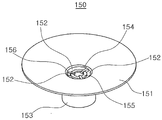
- FIG. 3 is an enlarged perspective view of the pressing plate of FIG. 1;
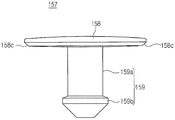
- Figure 4 is a side view of the leak stopper of Figure 1;
- FIG. 5 is a schematic perspective view of a dispenser cover of the prior art
- FIG. 6 is a schematic cross-sectional view of the dispenser cover of FIG. 5.
- the dispenser 100 for a liquid container of the present embodiment includes a cap 110, a suction unit 130 and the operation unit 150.
- Cap 110 is to install the dispenser 100 to the container 2 detachably, the mounting recess 111 is formed on the upper surface, the through hole 112 in the center of the mounting recess 111 Is formed. Cap 110 is provided with a lid 113 covering the mounting recess 111 on one side of the upper surface via the elastic plate 114, the bottom 115 is provided with an installation portion 115 facing down along the edge. On the inner surface of the mounting portion 115, a thread 116 is formed which is engaged with a thread formed in the opening of the container 2.
- the suction unit 130 is for discharging the contents in the container 2 to the outside, the mounting plate 131 is provided to be tightly fitted inside the mounting portion 115 of the cap 110, the mounting plate 131 In the center of the hollow stem pillar 132 facing down is provided.
- the stem pillar 132 is provided with a discharge part 133 penetrating the through hole 112 and an induction pipe 134 extending to the inside of the container 2, preferably to the bottom surface.
- the operation unit 150 is for operating the suction unit 130 while being pressed by an external force, and as shown in an enlarged view in FIG. 3, a concave dish having a shape corresponding to the installation recess 111 of the cap 110.
- a shape press plate 151 is provided, and a plurality of liquid exit holes 152 are formed in the center of the press plate 151.
- the operation unit 150 is provided such that the fitting boss 153 facing downward on the bottom surface of the pressing plate 151 is connected to the plurality of liquid discharge holes 152.
- the fitting boss 153 fits comfortably in the through hole 112 formed in the cap 110, while the discharging part 133 of the suction part 130 protrudes upward through the through hole 112 is the fitting boss. (153) is fitted tightly.
- a through hole 154 is formed in the center of the pressing plate 151, and an installation ring 155 is fixed in the through hole 154 via a plurality of legs 156. It is prepared. A plurality of leaking holes 152 of the pressing plate 151 is fitted with a leak stopper 157 to prevent the leakage of the contents.
- the stopper stopper 157 includes a stopper plate 158 that blocks a plurality of exit holes 152 and a mounting ring 155 facing downward from the bottom of the stopper plate 158. It has a fitting protrusion 159 that is fitted to).
- Leakage stopper 157 is made of a product that is excellent in workability, excellent in abrasion resistance, tear resistance, and bend resistance, and can maintain physical properties even when a large amount of filler is added.
- This product copolymerizes butadiene and styrene by low temperature emulsion polymerization method to make SBR latex with 5.5 wt% of bound styrene, and then mixes high styrene resin latex to finally total 21 wt% of styrene It is manufactured by adjusting to%, and the mixing dispersion and workability is very good and has the characteristics of improving the stiffness of the workpiece.
- the product used to manufacture the leak stopper 157 is 100-120 (kgf / cm 2) 300% tensile stress, 120-140 (kgf / cm 2) tensile strength, 380-400 (% Elongation), and hardness of 85-97 (Shore-A).
- the closure plate 158 has a slightly convex shape as the top surface is slightly inclined toward the edge from the center.
- the edge of the closure plate 158 is formed with an inclined portion 158c with the bottom surface slanted, and the inclined portion 158c starts at about 1/2 of the total thickness of the closure plate 158.
- the inclined portion 158c is precisely fitted to the rim inclined into the through hole 154 formed to slightly enter the pressing plate 151 of the operation portion 150 inward. Therefore, the stopper plate 158 completely blocks the through hole 154 of the pressing plate 151 so that the contents therein do not leak to the outside through the dispenser 100 even when the container 2 is inclined, lying down or upside down. Will not.
- the fitting protrusion 159 has a protrusion body 159a fitted to the installation ring 155 and an extension part 159b extending slightly outward from the protrusion body 159a. It is preferable that the protrusion body 159a is formed to be somewhat larger than the inner diameter of the installation ring 155, and the extension portion 159b is preferably formed to be somewhat smaller than the outer diameter of the installation ring 155. The extension part 159b is inclined to be inclined so as to be easily fitted to the installation ring 155.
- the diameter of the stopper plate 158 is preferably about 2.5-3.0 times the diameter of the fitting protrusion 159.
- the plurality of liquid exit holes 152 are blocked by the leak stopper plug 157, and the fitting boss 153 of the operation unit 150 slightly protrudes to the outside through the through hole 112 formed in the center of the cap 110.
- the pressing plate 151 of the actuating part 150 is pressed by the external force while being tightly fitted to the extracted liquid extracting part 133, the liquid extracting part 133 is pressed and the container along the induction pipe 134 provided in the suction part 130. 2)
- the contents contained inside are sucked up.
- the suctioned contents are discharged to the plurality of discharge holes 152 through the discharge portion 133, and the discharge pressure of the discharged contents overcomes the elastic force of the stopper plate 158 of the leak stopper 157. It is discharged to the outside.
- the discharge pressure is gradually reduced to the same as the internal pressure of the container 2 containing the contents.
- the elastic force of the stopper plate 158 is to overcome the reduced discharge pressure or the internal pressure so that the stopper plate 158 completely closes the outlet hole 152 again. Therefore, when the pressing plate 151 is not pressed, the contents are not discharged to the outside through the dispenser 100 even when the container 2 is inclined, lying down, or even turned upside down.
- liquid storage container dispenser of the present invention has been described above with reference to a preferred embodiment, it will be apparent to those skilled in the art that various changes, modifications, or variations are possible without departing from the spirit of the present invention.
Landscapes
- Engineering & Computer Science (AREA)
- Mechanical Engineering (AREA)
- Closures For Containers (AREA)
- Containers And Packaging Bodies Having A Special Means To Remove Contents (AREA)
Abstract
본 발명의 액체보관용기용 디스펜서(100)는 용기(2)에 분리 가능하게 설치되는 캡(110), 캡(110)에 설치되어 용기(2) 안에 보관된 내용물을 흡인하기 위한 흡인부(130), 외력에 의해 눌리면서 흡인부(130)를 작동시키기 위한 작동부(150)를 포함하고, 작동부(150)는 흡인부(130)의 출액부(133)와 연결되는 다수의 출액구멍(152)들이 중앙에 형성된 누름판(151)을 갖고, 다수의 출액구멍(152)들은 내용물의 토출압력에 따라 개폐되는 누출저지마개(157)에 의해 막혀진다.
Description
본 발명은 액체보관용기용 디스펜서에 관한 것으로, 더욱 상세하게는 용기를 기울이거나 뒤집어도 안에 보관된 내용물, 예를 들어 세제, 약액 또는 미용액 등과 같은 특히 액상 상태의 물체가 디스펜서의 출액구멍을 통해 외부로 누출되지 않는 액체보관용기용 디스펜서에 관한 것이다.
디스펜서는 용기 안에 보관된 내용물, 예를 들어 세제, 약액 또는 미용액과 같은 액상 물체를 외력을 인가 받아 외부로 토출시키기 위한 장치이다. 디스펜서가 액체가 보관된 용기에 적용된 예가 일본실용신안등록 제3121097호의 「디스펜서 커버」에 개시되어 있다.
도 5는 종래 디스펜서 커버(1)를 나타내는 분해 사시도이고, 도 6은 그 단면도이다.
도 5 및 도 6에 도시된 바와 같이, 종래의 디스펜서 커버(1)는 캡(10), 흡인부(20) 및 헤드(30)를 구비하고 있다.
캡(10)은 설치부(11)를 갖고 있고, 설치부(11)의 바닥면에는 설치오목부(12)가 형성되어 있고 상면 중앙에는 관통공(13)이 형성되어 있다. 또한 관통공(13)에는 설치오목부(12)까지 아래로 향하는 연결부(14)가 설치되어 있고, 설치오목부(12)의 내측면에는 용기(2)의 개구에 설치되도록 나사산이 형성되어 있다.
흡인부(20)는 캡(10)의 연결부(14)와 연결되고, 관통공(13)을 관통하는 출액부(21)와 용기(2) 안까지 연장되는 유도관(22)을 갖고 있다.
헤드(30)는 바닥면에 캡(10)의 설치부(11)에 설치되는 연결오목부(31)가 형성되고, 상면에는 적어도 하나의 출액구멍(33)을 갖는 수용오목부(32)가 형성된다. 또한 헤드(30)는 출액구멍(33)의 하부에 출액부(21)와 연결되는 접속관(34)이 설치되고, 일측에는 수용오목부(32)를 덮는 뚜껑(35)이 탄성판(36)을 매개로 설치되어 있다.
상술한 구성을 갖는 내용물이 점도가 낮은 액체일 경우 용기가 기울어지거나 거꾸로 뒤집혔을 때 출액구멍(33)을 통해 내용물이 외부로 흘러 나와 디스펜서 커버(1)나 용기(2)가 오염되는 문제가 있었다.
또한 이와 같은 디스펜서 커버(1)가 적용된 용기(2)의 내용물이 점도가 낮은 액체일 경우에는 사용자가 용기(2)를 가방 등에 넣고 다니면서 사용할 경우 내용물이 새어나와 다른 소지품이나 가방 등을 오염시키는 문제가 있었다.
또한 일단 사용 후 장시간 방치되는 경우 출액구멍(33) 속에 남아있는 내용물이 공기 중에 노출되어 상하게 되는 문제가 있었다.
본 발명은 상술한 종래기술의 문제점을 해결하기 위하여 창안한 것으로, 본 발명의 해결하고자 하는 과제는 용기 안의 내용물이 나오는 디스펜서의 출액구멍을 선택적으로 막음으로써 용기가 기울어지거나 거꾸로 뒤집힐 때에도 내용물이 출액구멍을 통해 외부로 흘러 나오지 않는 액체보관용기용 디스펜서를 제공하는 것이다.
본 발명의 과제를 달성하기 위하여, 본 발명은 용기에 분리 가능하게 설치되는 캡, 캡에 설치되어 용기 안에 보관된 내용물을 흡인하기 위한 흡인부, 외력에 의해 눌리면서 흡인부를 작동시키기 위한 작동부를 포함하고, 작동부는 흡인부의 출액부와 연결되는 다수의 출액구멍들이 중앙에 형성된 누름판을 갖고, 다수의 출액구멍들은 내용물의 토출압력에 따라 개폐되는 누출저지마개에 의해 막혀지는 것을 특징으로 하는 액체보관용기용 디스펜서를 제공한다.
본 발명에서, 캡은 중앙에 관통공이 형성된 설치오목부가 상면에 형성되고, 그 일측에 설치오목부를 덮는 뚜껑이 탄성판을 매개로 마련되고, 바닥면에는 용기와 결합되는 설치부가 마련되는 것을 특징으로 하고, 흡인부는 캡의 설치부 내측에 꽉 끼워지는 설치판이 마련되고, 설치판의 중앙에는 아래로 향하는 속이 빈 줄기기둥이 마련되고, 줄기기둥에는 관통공을 관통하는 출액부 및 용기 안까지 연장되는 유도관이 마련되는 것을 다른 특징으로 한다.
여기서, 작동부는 누름판의 바닥면에 다수의 출액구멍들과 이어지는 끼움보스가 마련되고, 끼움보스는 흡인부의 상기 출액부에 꽉 끼워지는 것을 특징으로 한다.
또한 누름판은 중앙에 관통공이 형성되고, 관통공 안에는 설치고리가 다수의 다리들을 매개로 고정되게 마련되는 것을 특징으로 하고, 누출저지마개는 누름판의 관통공을 막는 마개판 및 설치고리에 끼워지는 끼움돌기를 갖는 것을 다른 특징으로 하고, 마개판은 상면이 중앙에서 테두리로 갈수록 약간 경사져서 전체적으로 볼록한 형상을 갖고, 테두리는 바닥면이 경사지게 깍여진 경사부가 형성되는 것을 또 다른 특징으로 한다. 또한 경사부는 마개판 전체 두께의 약 1/2정도에서 시작되는 것을 또 다른 특징으로 한다.
또한 끼움돌기는 설치고리에 끼워지는 돌기몸체 및 돌기몸체에서 바깥쪽으로 연장되는 연장부를 가지며, 돌기몸체는 그 외경이 설치고리의 내경 보다 크고, 연장부는 설치고리의 외경 보다 작은 것을 특징으로 하고, 연장부는 설치고리에의 끼움이 용이하도록 바닥면이 경사지게 깍여지는 것을 다른 특징으로 한다.
또한 마개판은 그 직경이 끼움돌기의 직경의 2.5-3.0배인 것을 특징으로 한다.
본 발명에서, 누출저지마개는 가공성, 내마모성, 인열저항, 내굴곡성이 우수하고, 다량의 충진제 첨가에도 우수한 물성을 유지하는 것을 특징으로 하고, 누출저지마개는 100-120(kgf/㎠)의 300%인장응력, 120-140(kgf/㎠)의 인장강도, 380-400(%)의 신장률, 85-97(Shore-A)의 경도를 갖는 제품으로 만들어지는 것을 다른 특징으로 한다.
본 발명의 액체보관용기용 디스펜서는 내용물의 누출을 막는 누출저지마개가 출액구멍에 설치되기 때문에 점도가 매우 낮은 세제, 약액, 또는 미용액이 보관된 용기에 적용되더어 심지어 용기가 기울어지거나 거꾸로 뒤집힐 때에도 내용물이 외부로 흘러 나오지 않을 수 있다.
또한 사용자가 이와 같은 디스펜서가 적용된 용기를 가방 등에 소지하고 다닐 경우에는 내용물의 흘림이 없기 때문에 다른 소지품들이나 가방 등이 오염되지 않을 수 있다.
또한 일단 사용 후 장시간 방치되는 경우에도 출액구멍 속에 남아있는 내용물이 공기 중에 노출되지 않기 때문에 내용물이 상함을 막을 수 있다.
도 1은 본 발명의 바람직한 실시예에 따른 액체보관용기용 디스펜서의 개략적인 사시도;
도 2는 도 1의 개략적인 단면도;
도 3은 도 1의 누름판의 확대 사시도;
도 4는 도 1의 누출저지마개의 측면도;
도 5는 종래기술의 디스펜서 커버의 개략적인 사시도;
도 6은 도 5의 디스펜서 커버의 개략적인 단면도이다.
이하, 첨부한 도면을 참조로 본 발명의 바람직한 실시예에 따른 액체보관용기용 디스펜서에 대하여 상세하게 설명한다.
도 1 및 도 2에 도시한 바와 같이, 본 실시예의 액체보관용기용 디스펜서(100)는 캡(110), 흡인부(130) 및 작동부(150)를 포함한다.
캡(110)은 디스펜서(100)를 용기(2)에 분리 가능하게 설치하기 위한 것으로, 상면에 설치오목부(111)가 형성되고, 설치오목부(111)의 중앙에는 관통공(112)이 형성된다. 캡(110)은 상면 일측에 설치오목부(111)를 덮는 뚜껑(113)이 탄성판(114)을 매개로 마련되고, 바닥면에는 가장자리를 따라 아래로 향하는 설치부(115)가 마련된다. 설치부(115)의 내측면에는 용기(2)의 개구에 형성된 나사산과 결합되는 나사산(116)이 형성된다.
흡인부(130)는 용기(2) 안에 있는 내용물을 외부로 토출시키기 위한 것으로, 캡(110)의 설치부(115) 내측에 꽉 끼워지는 설치판(131)이 마련되고, 설치판(131)의 중앙에는 아래로 향하는 속이 빈 줄기기둥(132)이 마련된다. 줄기기둥(132)에는 관통공(112)을 관통하는 출액부(133)와 용기(2) 안까지, 바람직하게는 거의 바닥면까지 연장되는 유도관(134)이 마련된다.
작동부(150)는 외력에 의해 눌리면서 흡인부(130)를 작동시키기 위한 것으로, 도 3에 확대하여 도시한 바와 같이, 캡(110)의 설치오목부(111)와 대응하는 형상을 갖는 오목한 접시 모양의 누름판(151)이 마련되고, 누름판(151)의 중앙에는 다수의 출액구멍(152)들이 형성된다. 작동부(150)는 누름판(151)의 바닥면에 아래로 향하는 끼움보스(153)가 다수의 출액구멍(152)들과 이어지게 마련된다.
끼움보스(153)는 캡(110)에 형성된 관통공(112)에 여유있게 끼워지는 한편, 관통공(112)을 통해 위로 다소 돌출되는 흡인부(130)의 출액부(133)는 이 끼움보스(153)에 꽉 끼워진다.
다수의 출액구멍(152)들을 마련하기 위해서는, 누름판(151)의 중앙에 관통공(154)이 형성되고 이 관통공(154) 안에 설치고리(155)가 다수의 다리(156)들을 매개로 고정되게 마련된다. 누름판(151)의 다수의 출액구멍(152)들에는 내용물의 누출을 막기 위한 누출저지마개(157)가 끼워진다.
누출저지마개(157)는, 도 4에 확대하여 도시한 바와 같이, 다수의 출액구멍(152)들을 막는 마개판(158)과 이 마개판(158)의 바닥면에서 아래로 향하여 설치고리(155)에 끼워지는 끼움돌기(159)를 갖는다.
누출저지마개(157)는 가공성이 우수하고, 내마모성, 인열저항, 내굴곡성이 우수하고, 또한 다량의 충진제를 첨가하여도 좋은 물성을 유지할 수 있는 제품으로 제조하였다. 이 제품은 부타디엔과 스타이렌을 저온 유화중합법으로 공중합시켜 결합 스타이렌 함량 5.5wt%의 SBR 라텍스를 제조한 후 고 스타이렌 수지 라텍스(High Styrene Resin Latex)를 혼합하여 최종적으로 총 스타이렌 함량 21wt%로 조절하여 제조된 것으로, 배합분산성과 가공성이 매우 좋으며 가공품의 강도(stiffness)를 향상시키는 특징을 갖는다. 본 실시예에서, 누출저지마개(157)를 제조하는 데 사용되는 제품은 100-120(kgf/㎠)의 300%인장응력, 120-140(kgf/㎠)의 인장강도, 380-400(%)의 신장률, 85-97(Shore-A)의 경도를 갖는 것이 바람직하다.
마개판(158)은 상면이 중앙에서 테두리로 갈수록 약간 경사져서 전체적으로 약간 볼록한 형상을 갖는다. 마개판(158)의 테두리는 바닥면이 경사지게 깍여진 경사부(158c)가 형성되고, 이 경사부(158c)는 마개판(158) 전체 두께의 약 1/2정도에서 시작된다. 이 경사부(158c)는 작동부(150)의 누름판(151)에 안쪽으로 약간 들어가게 형성된 관통공(154)의 안으로 경사진 테두리에 정확히 맞춰진다. 따라서 마개판(158)이 누름판(151)의 관통공(154)을 완전히 막게 되어 용기(2)가 기울어지거나, 눕혀지거나 또는 거꾸로 놓여도 그 안에 있는 내용물이 디스펜서(100)를 통해 외부로 누출되지 않게 된다.
끼움돌기(159)는 설치고리(155)에 끼워지는 돌기몸체(159a)와 이 돌기몸체(159a)에서 바깥쪽으로 약간 연장되는 연장부(159b)를 갖는다. 돌기몸체(159a)는 그 외경이 설치고리(155)의 내경 보다 다소 크게 형성되는 것이 바람직하고, 연장부(159b)는 설치고리(155)의 외경 보다 다소 작게 형성되는 것이 바람직하다. 연장부(159b)는 설치고리(155)에의 끼움이 용이하도록 바닥면이 경사지게 깍여진다.
여기서, 마개판(158)의 직경은 끼움돌기(159)의 직경의 약 2.5-3.0배인 것이 바람직하다.
상술한 구성을 갖는 본 발명의 액체보관용기용 디스펜서의 작용에 대하여 설명한다.
다수의 출액구멍(152)들이 누출저지마개(157)에 의해 막혀지고, 작동부(150)의 끼움보스(153)가 캡(110)의 중앙에 형성된 관통공(112)을 통해 외부로 약간 돌출된 출액부(133)에 꽉 끼워진 상태에서, 외력에 의해 작동부(150)의 누름판(151)이 눌리면 출액부(133)가 눌리면서 흡인부(130)에 마련된 유도관(134)을 따라 용기(2) 안에 담겨 있던 내용물이 위로 흡인된다. 흡인된 내용물은 출액부(133)를 거쳐 다수의 출액구멍(152)들쪽으로 나오게 되고, 이때 출액되는 내용물의 토출압력이 누출저지마개(157)의 마개판(158)의 탄성력을 이기게 되어 내용물이 외부로 토출되게 된다.
한편, 작동부(150)의 누름판(151)에 가해져던 외력이 제거되면, 토출압력이 점차 줄어들어 내용물이 담기 용기(2)의 내부 압력과 거의 같아지게 된다. 이때, 마개판(158)의 탄성력은 줄어든 토출압력 또는 내부 압력을 이기게 되어 마개판(158)은 다시 출액구멍(152)들을 완전히 막게 된다. 따라서 누름판(151)이 눌리지 않을 경우에는 용기(2)가 기울어지거나 눕혀지거나 심지어 거꾸로 뒤집히더라도 디스펜서(100)를 통해 내용물이 외부로 토출되지 않게 된다.
이상, 바람직한 실시예를 참조로 본 발명의 액체보관용기용 디스펜서에 대하여 설명하였지만, 본 발명의 사상을 벗어나지 않는 범위 내에서 다양한 변경, 수정 또는 변형이 가능함은 당업자에게 명백하다.
Claims (13)
- 용기에 분리 가능하게 설치되는 캡;상기 캡에 설치되어 상기 용기 안에 보관된 내용물을 흡인하기 위한 흡인부;외력에 의해 눌리면서 흡인부를 작동시키기 위한 작동부를 포함하고,상기 작동부는 상기 흡인부의 출액부와 연결되는 다수의 출액구멍들이 중앙에 형성된 누름판을 갖고, 상기 다수의 출액구멍들은 상기 내용물의 토출압력에 따라 개폐되는 누출저지마개에 의해 막혀지는 것을 특징으로 하는 액체보관용기용 디스펜서.
- 제1항에 있어서, 상기 캡은 중앙에 관통공이 형성된 설치오목부가 상면에 형성되고, 그 일측에 상기 설치오목부를 덮는 뚜껑이 탄성판을 매개로 마련되고, 바닥면에는 상기 용기와 결합되는 설치부가 마련되는 것을 특징으로 하는 액체보관용기용 디스펜서.
- 제2항에 있어서, 상기 흡인부는 상기 캡의 설치부 내측에 꽉 끼워지는 설치판이 마련되고, 상기 설치판의 중앙에는 아래로 향하는 속이 빈 줄기기둥이 마련되고, 상기 줄기기둥에는 상기 관통공을 관통하는 출액부 및 상기 용기 안까지 연장되는 유도관이 마련되는 것을 특징으로 하는 액체보관용기용 디스펜서.
- 제1항 내지 제3항 중 어느 한 항에 있어서, 상기 작동부는 상기 누름판의 바닥면에 상기 다수의 출액구멍들과 이어지는 끼움보스가 마련되고, 상기 끼움보스는 상기 흡인부의 상기 출액부에 꽉 끼워지는 것을 특징으로 하는 액체보관용기용 디스펜서.
- 제1항 내지 제3항 중 어느 한 항에 있어서, 상기 누름판은 중앙에 관통공이 형성되고, 상기 관통공 안에는 설치고리가 다수의 다리들을 매개로 고정되게 마련되는 것을 특징으로 하는 액체보관용기용 디스펜서.
- 제5항에 있어서, 상기 누출저지마개는 상기 누름판의 상기 관통공을 막는 마개판 및 상기 설치고리에 끼워지는 끼움돌기를 갖는 것을 특징으로 하는 액체보관용기용 디스펜서.
- 제6항에 있어서, 상기 마개판은 상면이 중앙에서 테두리로 갈수록 약간 경사져서 전체적으로 볼록한 형상을 갖고, 상기 테두리는 바닥면이 경사지게 깍여진 경사부가 형성되는 것을 특징으로 하는 액체보관용기용 디스펜서.
- 제7항에 있어서, 상기 경사부는 상기 마개판 전체 두께의 약 1/2정도에서 시작되는 것을 특징으로 하는 액체보관용기용 디스펜서.
- 제6항에 있어서, 상기 끼움돌기는 상기 설치고리에 끼워지는 돌기몸체 및 상기 돌기몸체에서 바깥쪽으로 연장되는 연장부를 가지며, 상기 돌기몸체는 그 외경이 상기 설치고리의 내경 보다 크고, 상기 연장부는 상기 설치고리의 외경 보다 작은 것을 특징으로 하는 액체보관용기용 디스펜서.
- 제9항에 있어서, 상기 연장부는 상기 설치고리에의 끼움이 용이하도록 바닥면이 경사지게 깍여지는 것을 특징으로 하는 액체보관용기용 디스펜서.
- 제6항에 있어서, 상기 마개판은 그 직경이 상기 끼움돌기의 직경의 2.5-3.0배인 것을 특징으로 하는 액체보관용기용 디스펜서.
- 제1항에 있어서, 상기 누출저지마개는 가공성, 내마모성, 인열저항, 내굴곡성이 우수하고, 다량의 충진제 첨가에도 우수한 물성을 유지하는 것을 특징으로 하는 액체보관용기용 디스펜서.
- 제12항에 있어서, 상기 누출저지마개는 100-120(kgf/㎠)의 300%인장응력, 120-140(kgf/㎠)의 인장강도, 380-400(%)의 신장률, 85-97(Shore-A)의 경도를 갖는 제품으로 만들어지는 것을 특징으로 하는 액체보관용기용 디스펜서.
Applications Claiming Priority (2)
| Application Number | Priority Date | Filing Date | Title |
|---|---|---|---|
| KR1020090035179A KR101075887B1 (ko) | 2009-04-22 | 2009-04-22 | 액체보관용기용 디스펜서 |
| KR10-2009-0035179 | 2009-04-22 |
Publications (2)
| Publication Number | Publication Date |
|---|---|
| WO2010123233A2 true WO2010123233A2 (ko) | 2010-10-28 |
| WO2010123233A3 WO2010123233A3 (ko) | 2011-03-31 |
Family
ID=43011579
Family Applications (1)
| Application Number | Title | Priority Date | Filing Date |
|---|---|---|---|
| PCT/KR2010/002412 Ceased WO2010123233A2 (ko) | 2009-04-22 | 2010-04-19 | 액체보관용기용 디스펜서 |
Country Status (2)
| Country | Link |
|---|---|
| KR (1) | KR101075887B1 (ko) |
| WO (1) | WO2010123233A2 (ko) |
Cited By (2)
| Publication number | Priority date | Publication date | Assignee | Title |
|---|---|---|---|---|
| EP3023025A4 (en) * | 2013-08-22 | 2017-04-05 | Pum-Tech Korea Co., Ltd | Cosmetic container capable of storing and discharging two kinds of contents |
| CN110179379A (zh) * | 2019-05-14 | 2019-08-30 | 东营市浩瀚生化科技有限公司 | 一种上出液的洗手液存放装置 |
Families Citing this family (3)
| Publication number | Priority date | Publication date | Assignee | Title |
|---|---|---|---|---|
| KR101454748B1 (ko) * | 2013-05-24 | 2014-10-27 | (주)연우 | 액상 내용물의 정량 인출이 가능한 용기 |
| KR101467198B1 (ko) * | 2013-05-24 | 2014-12-01 | (주)연우 | 액상 내용물의 정량 인출이 가능한 용기 |
| KR102924384B1 (ko) * | 2021-04-21 | 2026-02-06 | (주)아모레퍼시픽 | 화장품 용기 |
Family Cites Families (6)
| Publication number | Priority date | Publication date | Assignee | Title |
|---|---|---|---|---|
| KR0175208B1 (ko) * | 1995-07-07 | 1999-04-15 | 김경숙 | 자동개폐캡 및 내용액 자동토출방법 |
| JP4021268B2 (ja) | 2002-07-24 | 2007-12-12 | 勝利 増田 | 流体吐出ポンプ |
| JP3993487B2 (ja) * | 2002-07-26 | 2007-10-17 | 勝利 増田 | 流動体のチューブ型容器 |
| KR200301585Y1 (ko) | 2002-10-21 | 2003-01-24 | 안돈례 | 병마개 조립체 |
| KR100545007B1 (ko) * | 2004-05-31 | 2006-01-24 | 윤석관 | 화장품 용기의 펌핑장치 |
| JP3121097U (ja) * | 2006-02-01 | 2006-04-27 | 牧信企業股▲分▼有限公司 | ディスペンサーカバー |
-
2009
- 2009-04-22 KR KR1020090035179A patent/KR101075887B1/ko not_active Expired - Fee Related
-
2010
- 2010-04-19 WO PCT/KR2010/002412 patent/WO2010123233A2/ko not_active Ceased
Cited By (2)
| Publication number | Priority date | Publication date | Assignee | Title |
|---|---|---|---|---|
| EP3023025A4 (en) * | 2013-08-22 | 2017-04-05 | Pum-Tech Korea Co., Ltd | Cosmetic container capable of storing and discharging two kinds of contents |
| CN110179379A (zh) * | 2019-05-14 | 2019-08-30 | 东营市浩瀚生化科技有限公司 | 一种上出液的洗手液存放装置 |
Also Published As
| Publication number | Publication date |
|---|---|
| KR20100116457A (ko) | 2010-11-01 |
| KR101075887B1 (ko) | 2011-10-25 |
| WO2010123233A3 (ko) | 2011-03-31 |
Similar Documents
| Publication | Publication Date | Title |
|---|---|---|
| WO2010123233A2 (ko) | 액체보관용기용 디스펜서 | |
| WO2015147504A2 (ko) | 크림타입 화장품 용기 | |
| EP2719635B1 (en) | Dispensing container | |
| US9617051B2 (en) | Bottle cap | |
| WO2015088091A1 (ko) | 크림타입 화장품 용기 | |
| WO2009091173A2 (ko) | 수동식 분사펌프 | |
| WO2010050772A2 (ko) | 액체 저장용기의 펌핑장치 | |
| WO2022092584A1 (ko) | 내용물 용기 | |
| WO2013125813A1 (en) | Rubber seal for vacuum receptacle and lid for the receptacle using the same | |
| WO2014189213A1 (ko) | 회전 토출식 화장품 용기 | |
| WO2015147505A1 (ko) | 크림타입 화장품 용기 | |
| WO2009099285A2 (ko) | 수동식 드롭퍼 | |
| WO2016117850A1 (ko) | 필터를 구비한 이중 음료용기 | |
| WO2017204381A1 (ko) | 카트리지 펌프 | |
| WO2015147526A1 (ko) | 펌핑식 화장품 용기 | |
| KR20140006232U (ko) | 누액 방지 기능을 갖는 화장품 펌프용기 | |
| WO2018008894A1 (ko) | 진공밀폐 용기 | |
| WO2020251317A1 (ko) | 손잡이 하부에 따개가 형성된 수직형 병따개 | |
| US20120118893A1 (en) | Container cover | |
| KR101984273B1 (ko) | 분리형 화장품 용기 | |
| WO2012005441A2 (ko) | 에어리스 타입 화장품 용기의 피스톤 | |
| WO2011046251A1 (ko) | 병마개 조립체 | |
| WO2021045517A1 (ko) | 일회용 컵 뚜껑 | |
| WO2015105285A1 (ko) | 이중 컵 | |
| KR101569493B1 (ko) | 병뚜껑 |
Legal Events
| Date | Code | Title | Description |
|---|---|---|---|
| 121 | Ep: the epo has been informed by wipo that ep was designated in this application |
Ref document number: 10767247 Country of ref document: EP Kind code of ref document: A2 |
|
| NENP | Non-entry into the national phase |
Ref country code: DE |
|
| 122 | Ep: pct application non-entry in european phase |
Ref document number: 10767247 Country of ref document: EP Kind code of ref document: A2 |