WO2010123022A1 - 通信装置及び通信システム - Google Patents
通信装置及び通信システム Download PDFInfo
- Publication number
- WO2010123022A1 WO2010123022A1 PCT/JP2010/057050 JP2010057050W WO2010123022A1 WO 2010123022 A1 WO2010123022 A1 WO 2010123022A1 JP 2010057050 W JP2010057050 W JP 2010057050W WO 2010123022 A1 WO2010123022 A1 WO 2010123022A1
- Authority
- WO
- WIPO (PCT)
- Prior art keywords
- transmission power
- signal
- transmission
- unit
- communication
- Prior art date
- Legal status (The legal status is an assumption and is not a legal conclusion. Google has not performed a legal analysis and makes no representation as to the accuracy of the status listed.)
- Ceased
Links
Images


Classifications
-
- H—ELECTRICITY
- H04—ELECTRIC COMMUNICATION TECHNIQUE
- H04W—WIRELESS COMMUNICATION NETWORKS
- H04W52/00—Power management, e.g. Transmission Power Control [TPC] or power classes
- H04W52/04—Transmission power control [TPC]
- H04W52/18—TPC being performed according to specific parameters
- H04W52/28—TPC being performed according to specific parameters using user profile, e.g. mobile speed, priority or network state, e.g. standby, idle or non-transmission
- H04W52/288—TPC being performed according to specific parameters using user profile, e.g. mobile speed, priority or network state, e.g. standby, idle or non-transmission taking into account the usage mode, e.g. hands-free, data transmission or telephone
Definitions
- the present invention relates to a communication device that transmits a signal and a communication system that includes the communication device.
- transmission power power of a transmission signal
- FIG. 3 is a block diagram showing a configuration of a conventional communication apparatus.
- the communication apparatus 100 includes a modulation unit 101 that modulates transmission data, a transmission side amplification unit 102 that amplifies a signal modulated by the modulation unit 101, and a signal output from the transmission side amplification unit 102.
- a transmission-side mixing unit 103 that mixes a signal of a predetermined frequency
- a transmission-side oscillation unit 104 that inputs a signal of a predetermined frequency to the transmission-side mixing unit 103, and a signal output from the transmission-side mixing unit 103
- a transmission side band pass filter (BPF) 105 that filters and outputs components other than frequency components
- an automatic amplification unit 106 that amplifies a signal output from the transmission side BPF 105, an automatic amplification unit 106, and an antenna 108 (described later).
- BPF 107 for antenna that outputs a signal other than a predetermined frequency component by filtering, and a signal input from automatic amplifying unit 106 via antenna BPF 107.
- An antenna 108 that wirelessly transmits a (transmission signal) and receives a signal (reception signal) transmitted from a communication partner, a reception-side amplification unit 109 that amplifies a signal input from the antenna 108 via the antenna BPF 107, A reception-side mixing unit 110 that mixes a signal of a predetermined frequency with a signal output from the reception-side amplification unit 109, a reception-side oscillation unit 111 that inputs a signal of a predetermined frequency to the reception-side mixing unit 110, and reception-side mixing A receiving BPF 112 that filters and outputs a signal other than a predetermined frequency component from the signal output from the unit 110; and a demodulating unit 113 that demodulates the signal output from the receiving BPF 112 to obtain received data.
- the communication apparatus 100 sets the amplification degree in the automatic amplification unit 106 based on the power of the signal output from the reception-side BPF 112 (that is, power resulting from the reception signal, hereinafter referred to as reception power).
- a setting unit 114 is provided.
- the amplification degree setting unit 114 sets the amplification degree in the automatic amplification unit 106 based on the received power, and optimizes the transmission power. That is, the communication apparatus 100 considers the state of the reception signal and the transmission signal to be the same, and controls the transmission power based on the reception power.
- the transmission state of the communication partner (transmission path state from the communication partner to the own device) is poor, even though the transmission state of the own device (transmission channel state from the own device to the communication partner) is good.
- the automatic amplifying unit 106 unnecessarily amplifies the transmission signal and increases the transmission power. In such a case, not only the power consumption is unnecessarily increased, but also interference is likely to occur in another communication system that performs communication using substantially the same channel (frequency band) as the communication device 100. Therefore, it becomes a problem.
- the automatic amplification unit 106 reduces the transmission power without amplifying the transmission signal so much. In such a case, since the transmission state of the own device is further deteriorated, the communication partner may eventually become unable to receive, which is a problem.
- the above situation is likely to occur when there are some differences in the transmission and reception states, such as different channels used for transmission and reception. Such a difference can naturally occur in the operation of the communication apparatus.
- an object of the present invention is to provide a communication device that can perform transmission power optimization with high accuracy and a communication system including the communication device.
- a communication system includes a first communication device that transmits a first signal and receives a second signal, and a second communication device that transmits the second signal and receives the first signal.
- the first communication device includes a first transmission power control unit that controls a first transmission power that is a transmission power of the first signal, and the second communication device receives a reception signal.
- a second state determination unit that determines a state of the first signal and generates first transmission power information; a second signal generation unit that generates the second signal including the first transmission power information;
- the first transmission power control unit acquires the first transmission power information from the received second signal, and controls the first transmission power based on the first transmission power information It is characterized by that.
- a transmission signal and a reception signal are cited as examples of the first signal and the second signal, and a transmission power setting unit and an amplification factor setting unit are listed as examples of the transmission power control unit.
- determination information and request information are cited.
- state determination unit the other party transmission state determination unit and memory, the other party transmission power request unit, and the combined data generation unit are cited.
- signal generation unit transmission data.
- the generation unit, the transmission data synthesis unit, the modulation unit, the transmission side amplification unit, the transmission side mixing unit, the transmission side oscillation unit, the transmission side BPF, the automatic amplification unit, and the antenna BPF will be described.
- the first transmission power control unit adjusts the first transmission power based on a state of the first signal to be transmitted.
- the first transmission power may be sufficiently larger than the minimum necessary transmission power obtained based on the first transmission power information ( It does not matter if the margin is increased).
- the first transmission power information may indicate a request to increase or decrease the first transmission power
- the first transmission power control unit includes the first transmission power control unit. It is preferable to control the first transmission power according to a request indicated by the transmission power information. In the communication system configured as described above, it is preferable that the first transmission power control unit controls the first transmission power for each predetermined stage.
- the first transmission power can be easily controlled.
- the second state determination unit may determine the state of the first signal based on the received error of the first signal.
- the second state determination unit may determine the state of the first signal based on the received BER of the first signal.
- the first communication device can control the first transmission power based on the error of the first signal received by the second communication device. Therefore, it is possible to effectively suppress the occurrence of an error in the first signal received by the second communication device.
- the first communication device further includes a storage unit that stores the first transmission power information, and communication between the first communication device and the second communication device is temporarily performed.
- the first transmission power control unit may set the first transmission power based on the first transmission power information stored in the storage unit.
- the first transmission power set at the time of restart can be set to an appropriate magnitude.
- the first transmission power control unit may maximize the first transmission power.
- the first communication device determines a state of the received second signal and generates second transmission power information
- the second transmission power A first signal generation unit that generates the first signal including information
- the second communication device controls a second transmission power that is a transmission power of the second signal.
- the second transmission power control unit acquires the second transmission power information from the received first signal, and controls the second transmission power based on the second transmission power information It is preferable to do.
- the communication device of the present invention is a communication device that wirelessly transmits a signal to a communication partner, a transmission power control unit that controls transmission power of the signal, and a transmission state detection unit that detects the transmission state of the signal And the transmission power control unit controls the transmission power based on the transmission state.
- the transmission power of the first communication device is set based on the state of the first signal. That is, the first transmission power of the first communication device is controlled based on the transmission path state from the first communication device to the second communication device. Therefore, the state of the first signal can be directly fed back to the magnitude of the first transmission power, and the first transmission power can be optimized with high accuracy. Therefore, it is possible to suppress interference with other communication systems or the reception failure of the second communication device. In addition, according to the communication device of the present invention, it is possible to optimize transmission power with high accuracy.
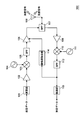
- FIG. 1 is a block diagram showing a configuration of a communication apparatus according to an embodiment of the present invention.
- the communication apparatus of the present invention is provided in a wireless transmission television system.
- the wireless transmission television system has a display unit for displaying images and playing back sound, and data such as moving images acquired by receiving broadcasts and reading from recording media into data that can be displayed on the display unit.
- a video source unit for converting and wirelessly transmitting to the display unit.
- the communication device 1 shown in FIG. 1 can be provided in either the display unit or the video source unit. Hereinafter, a case where the communication device 1 is provided in the video source unit will be described as an example.
- the communication device 1 includes a modulation unit 2 that modulates transmission data, a transmission side amplification unit 3 that amplifies a signal modulated by the modulation unit 2, and a signal output from the transmission side amplification unit 3.
- a transmission-side mixing unit 4 that mixes a signal of a predetermined frequency to the transmission-side mixing unit 4, a transmission-side oscillation unit 5 that inputs a signal of a predetermined frequency to the transmission-side mixing unit 4, and a signal output from the transmission-side mixing unit 4
- Transmission side BPF 6 that filters and outputs components other than frequency components
- automatic amplification unit 7 that amplifies a signal output from transmission side BPF 6, and a predetermined frequency from signals input from automatic amplification unit 7 and antenna 9 (described later)
- the antenna BPF 8 that filters and outputs components other than the components and the signal (transmission signal) input from the automatic amplifying unit 7 via the antenna BPF 8 are wirelessly transmitted and the signal (reception signal) transmitted from the communication partner is received.
- a receiving side amplifying unit 10 that amplifies a signal input from the antenna 9 via the antenna BPF 8
- a receiving side mixing unit 11 that mixes a signal output from the receiving side amplifying unit 10 with a signal of a predetermined frequency.
- a receiving-side oscillation unit 12 that inputs a signal of a predetermined frequency to the receiving-side mixing unit 11, a receiving-side BPF 13 that filters and outputs a signal other than a predetermined frequency component from the signal output from the receiving-side mixing unit 11,
- a demodulator 14 that demodulates a signal output from the receiving side BPF 13 to obtain received data.
- the communication device 1 determines the transmission state from the communication partner to the own device based on the state of the received data obtained by the demodulation unit 14 and outputs the determination information
- the partner side transmission Memory 16 that stores determination information output from state determination unit 15, and partner-side transmission that generates request information for transmission power of a signal (reception signal) transmitted by the communication partner based on the determination information stored in memory 16
- a transmission data synthesis unit 20 that synthesizes the synthesized data with the transmission data generated in step S4 and outputs the synthesized transmission data to the modulation unit 2.
- the communication apparatus 1 includes a transmission side transmission power request acquisition unit 21 that acquires request information for transmission power of the transmission signal of the own unit generated by the communication partner from the reception data obtained by the demodulation unit 14, and a transmission
- the data format acquisition unit 22 that acquires the format of the transmission data generated by the data generation unit 19, the request information acquired by the own-side transmission power request acquisition unit 21, and the transmission data acquired by the data format acquisition unit 22
- the self-side transmission power setting unit 23 that sets the transmission power of the communication device 1 based on the format, and the automatic amplification unit 7 so that the transmission power set by the self-side transmission power setting unit 23 is realized.
- an amplification degree setting unit 24 for setting the amplification degree.
- the modulation unit 2 modulates transmission data (details will be described later) output from the data synthesis unit 20 using a predetermined modulation method.
- error correction coding for example, outer coding is performed by block coding represented by Reed-Solomon coding or Hamming coding, and is represented by Viterbi algorithm or turbo coding). (Concatenated coding in which inner coding is performed by convolutional coding) may be performed.
- the modulated signal output from the modulation unit 2 is amplified by the transmission side amplification unit 3 and input to the transmission side mixing unit 4.
- the transmission-side mixing unit 4 is a signal including a frequency component obtained by adding the frequency of the signal input from the transmission-side oscillation unit 5 to the frequency of the signal input from the transmission-side amplification unit 3, and a subtracted frequency component. Output.
- the transmitting side BPF 6 passes the added frequency component out of these and filters other frequency components. In this manner, frequency conversion (up-conversion) to RF (Radio Frequency) is performed. Note that the transmission channel can be changed by appropriately changing the frequency of the signal output from the transmission-side oscillator 5.
- the signal output from the transmitting BPF 6 is amplified by the automatic amplifying unit 7 and input to the antenna BPF 8.
- the automatic amplifying unit 7 performs amplification with the amplification degree set by the amplification degree setting unit 24.
- the details of the amplification degree setting method by the post-amplification setting unit 24 will be described later.
- the antenna BPF 8 filters a frequency component (such as a noise component) that should not be included in the transmission signal from the signal input from the automatic amplification unit 7 and outputs the filtered signal to the antenna 9 as a transmission signal.
- the antenna 9 radiates the input transmission signal into the air and wirelessly transmits it to the communication partner.
- the antenna 9 receives a reception signal wirelessly transmitted from the communication partner and outputs it to the antenna BPF 8.
- the antenna BPF 8 filters out a frequency component (such as a noise component) that should not be included in the received signal from the received signal input from the antenna 9 and outputs the filtered signal to the receiving side amplification unit 10.
- the reception side amplification unit 10 amplifies the input signal and inputs the amplified signal to the reception side mixing unit 11.
- the reception side mixing unit 11 outputs a signal including a frequency component obtained by subtracting the frequency of the signal input from the reception side oscillation unit 12 from the frequency of the signal input from the reception side amplification unit 10 and the added frequency component. To do.
- the reception-side BPF 13 passes the subtracted frequency components and filters other frequency components. In this manner, frequency conversion (down conversion) to IF (IntermediatemediaFrequency) is performed.
- the reception channel can be changed by appropriately changing the frequency of the signal output from the reception-side oscillation unit 12.
- the signal output from the receiving BPF 13 is input to the demodulator 14.
- the demodulator 14 demodulates using a demodulation method corresponding to the modulation method used by the communication partner for modulation to obtain received data. Further, when the communication partner is performing error correction coding, the demodulator 14 decodes the received data using a decoding method corresponding to this coding method, and outputs the received data after error correction. Note that the communication device 1 uses the output received data for various purposes.
- the other party transmission state determination unit 15 determines the transmission state (transmission path state from the communication partner to the own device) on the other side based on the reception data obtained by the demodulation unit 14, generates determination information, and outputs it. . For example, when error correction of received data is performed, determination is performed using a BER (Bit Error Rate) that can be calculated as a secondary. In this case, determination information indicating that the transmission state of the other party is worse is generated as the BER is larger (the more bits are regarded as errors). The obtained BER time average value may be used as the determination information.
- BER Bit Error Rate
- the other party transmission state determination unit 15 monitors the transmission state of the other party constantly or at predetermined time intervals, and sequentially outputs determination information.
- the determination information sequentially output is input to the memory 16 and stored sequentially.
- the counterpart transmission power request unit 17 generates request information indicating a request for transmission power of the communication counterpart based on the determination information stored in the memory 16.
- the counterpart transmission power request unit 17 when the counterpart transmission power request unit 17 generates request information based on the determination information using the BER as in the above example, if the value of the BER is large, the communication counterpart is requested to increase the transmission power. Request information to be generated. On the other hand, if the BER value is small enough to be regarded as error-free (for example, if the BER value at the time of inner code decoding is 2 ⁇ 10 ⁇ 4 or less in the reception data subjected to the above-described concatenated coding) Request information for requesting the other party to suppress transmission power is generated. If the BER is in a state between these, request information may not be generated, or request information for requesting maintenance of transmission power may be generated.
- the composite data generation unit 18 generates composite data by combining the request information with other data transmitted to the communication partner. Then, the transmission data combining unit 20 combines the combined data with the transmission data generated by the transmission data generating unit 19 (for example, moving image data displayed on the display unit), and outputs the combined transmission data to the modulation unit 2. .
- the communication partner has a configuration corresponding to the counterpart transmission state determination unit 15, the memory 16, the counterpart transmission strength request unit 17, the composite data generation unit 18, and the transmission data synthesis unit 20 of FIG.
- the request information for the transmission power of the own device is generated and included in the received signal (signal transmitted by the communication partner).
- the communication partner does not have to have all of these, it has at least a configuration corresponding to the counterpart transmission state determination unit 15 in FIG. , BER).
- the own device side transmission power request acquisition unit 21 of the own device may generate the request information based on the transmission state notified from the communication partner, or the own device side transmission power setting unit 23 of the own device may The magnitude of the transmission power of the own device may be controlled based on the transmission state notified from the communication partner.
- the own-device-side transmission power request acquisition unit 21 acquires request information generated by the communication partner from the received data. Then, the acquired request information is input to the own-device-side transmission power setting unit 23. Also, the data format acquisition unit 22 acquires the format of transmission data generated by the transmission data generation unit 19 (for example, data amount, compression method, etc.) and inputs it to the own-device-side transmission power setting unit 23.
- the own-side transmission power setting unit 23 controls the magnitude of the own-device transmission power based on the request information acquired by the own-side transmission power request acquisition unit 21 in principle. If request information for increasing the transmission power of the own device is input, an instruction to increase the amplification is output to the amplification setting unit 24 in order to increase the transmission power of the own device. On the other hand, if request information for reducing the transmission power of the own device is input, an instruction for reducing the amplification factor is output to the amplification factor setting unit 24.
- the own device side transmission power setting unit 23 adjusts the transmission power of the own device based on the data format. For example, if it is preferable to increase transmission power and perform reliable transmission, such as when the amount of transmission data is large (such as high-definition image quality or low compression rate), the above request information The transmission power is made sufficiently large (with a large margin) from the minimum required size obtained based on the above. On the other hand, when it is expected that the transmission power does not need to be increased, for example, when the data amount of the transmission signal is small, the transmission power is set to be close to the minimum required size (with a reduced margin).
- the own-device side transmission power setting unit 23 can also control the above margin based on the modulation scheme by the modulation unit 2. For example, the margin may be increased as the transmission rate is increased.
- the adjustment may be performed based on either the data format or the modulation method. .
- the transmission power of the communication apparatus 1 will be set based on the state of the transmission signal which the communication apparatus 1 transmitted.
- the transmission power of the own device is controlled based on the state of the transmission path from the own device to the communication partner. Therefore, the state of the transmission signal can be directly fed back to the magnitude of the transmission power, and the transmission power can be optimized with high accuracy. Therefore, it is possible to suppress interference with other communication systems or the inability of the communication partner to receive.
- the transmission power of the communication partner can be optimized by including the request information for the transmission power of the communication partner in the transmission data. Therefore, both transmission powers can be optimized, and stable communication can be performed.
- the communication apparatus 1 of this example assumes the case where it is provided in a video source part, although the data of a moving image are mentioned as an example of transmission data, what kind of transmission data may be used.
- the remote controller input instruction (remote control code) transmitted to the video source unit via the display unit including the light receiving unit may be used as transmission data, and the transmission signal is normal.
- ACK acknowledgement
- a retransmission request signal, or the like that responds to the video source unit as reception data may be used as transmission data.
- one communication apparatus may perform the above-described transmission power optimization.
- one communication apparatus 1 that performs the above-described transmission power optimization does not include the counterpart transmission state determination unit 15, the memory 16, and the counterpart transmission power request unit 17.
- the other transmission apparatus 1 that does not perform may not include the own-side transmission power request acquisition unit 21 and the data format acquisition unit 22.
- the amplification degree that can be set by the own-side transmission power setting unit 23 and the amplification degree setting unit 24 may be set in stages.
- the maximum amplification degree that can be set, the amplification degree that is 3 dB or more lower than the maximum amplification degree, and each step obtained by dividing a plurality of intervals between them may be taken.
- This configuration makes it possible to control the amplification level in stages. Furthermore, if the request information is instructed stepwise (for example, instructing only up and down steps and transmission power increase / decrease), the configuration can be simplified.
- FIG. 2 is a flowchart illustrating an example of a communication operation of the communication apparatus according to the embodiment of the present invention. In the following, a case where the communication apparatuses 1 shown in FIG. 1 communicate with each other will be described as an example.
- communication is established prior to the communication operation shown in FIG. Specifically, for example, one communication device 1 searches for the other communication device 1 as a communication partner and determines a channel to be used for communication.
- one communication apparatus 1 performs carrier sense in order to confirm that a channel to be used for transmission is not used by another communication system (is an empty channel). Specifically, for example, one communication apparatus 1 confirms an empty channel by receiving a signal of a predetermined channel and confirming that the signal is not detected (received power is equal to or lower than a predetermined value).
- One communication apparatus 1 uses the confirmed empty channel and transmits the transmission signal with the maximum transmission power in order to increase the possibility that the other communication apparatus receives the transmission signal.
- ACK is transmitted to the one communication device 1 using a predetermined channel.
- communication establishment is performed when one communication apparatus 1 receives and confirms this ACK.
- the communication device 1 When communication is established, the communication device 1 starts the communication operation shown in FIG.
- the communication operation shown in FIG. 2 can be repeatedly performed in one communication device 1 and the other communication device 1.
- reception of a received signal is the starting point of a series of operations.
- the communication device 1 receives the received signal by the antenna 9 (STEP 1), and demodulates the received signal by the demodulator 14 to obtain received data ( (Step 2).
- the communication device 1 When the communication device 1 obtains the reception data in STEP 2, the communication device 1 generates a signal including request information for the transmission power of the communication partner (STEP 10 to STEP 15) and sets its own transmission power (STEP 20 to 20). (Step 23).
- the partner side transmission state determination unit 15 determines the transmission state from the communication partner to its own device by using the BER of the received data (STEP 10). Further, determination information generated by the determination is stored in the memory 16 (STEP 11). Then, the counterpart transmission power request unit 17 generates request information based on the determination information stored in the memory 16 (STEP 12), and the composite data generation unit 18 generates composite data including the request information (STEP 13). . Further, the transmission data combining unit 20 combines the combined data with the transmission data generated by the transmission data generating unit 19 (STEP 14), and the modulation unit 2 modulates the transmission data combined with the request information (STEP 15). Through the series of operations described above, a signal including request information for transmission power of the communication partner is generated.
- the own device-side transmission power request acquisition unit 21 acquires request information for the transmission power of the own device included in the received data (generated by the communication partner). (STEP 20). Further, the data format acquisition unit 22 acquires the data format of the transmission data transmitted by the own device (STEP 21). Then, the own transmission power setting unit 23 sets the magnitude of the transmission power based on the request information acquired in STEP 20 and the data format acquired in STEP 21 (STEP 22), and the amplification setting unit 24 automatically The amplification degree of the amplification unit 7 is set (STEP 23). Through the above series of operations, the transmission power of the own device is set.
- the signal including the request information for the transmission power of the communication partner generated in STEP 15 is subjected to various processes to generate a transmission signal (STEP 30).
- the automatic amplifying unit 7 amplifies the signal with the amplification degree set in STEP 23 to optimize the transmission power.
- the transmission signal generated in STEP 30 is transmitted from the antenna 9 (STEP 31).
- the request information set by the own-side transmission power request acquisition unit 21 is stored in the memory 16 or the like
- the request information may be read from the memory 16 or the like at the time of resumption and the transmission power may be set.
- the transmission power set by the own device-side transmission power setting unit 23, the amplification degree set by the amplification degree setting unit 24, and the like may be stored in the memory 16. If comprised in this way, it will become possible to make appropriate the transmission power at the time of restarting communication.
- the transmission power is maximized regardless of the request information stored in the memory 16 (for example, discarding). You may try to establish communication. If comprised in this way, it will become possible to improve possibility that a communicating party will receive a transmission signal.
- each part (for example, the other party transmission state determination part 15, the other party transmission power request
- a control device such as a microcomputer.
- all or part of the functions realized by such a control device are described as a program, and the program is executed on a program execution device (for example, a computer) to realize all or part of the functions. It doesn't matter if you do.
- the communication device 1 of FIG. 1 can be realized by hardware or a combination of hardware and software. Further, when a part of the communication device 1 is configured using software, a block diagram of a part realized by software represents a functional block diagram of the part.
- the present invention relates to a communication device that transmits a signal and a communication system that includes the communication device, and is preferably provided in a display unit, a video source unit, or the like of a wireless transmission television system.
Landscapes
- Engineering & Computer Science (AREA)
- Computer Networks & Wireless Communication (AREA)
- Signal Processing (AREA)
- Mobile Radio Communication Systems (AREA)
- Transmitters (AREA)
Abstract
Description
図1に示すように、通信装置1は、送信データを変調する変調部2と、変調部2で変調された信号を増幅する送信側増幅部3と、送信側増幅部3から出力される信号に所定の周波数の信号を混合する送信側混合部4と、送信側混合部4に所定の周波数の信号を入力する送信側発振部5と、送信側混合部4から出力される信号から所定の周波数成分以外を濾波して出力する送信側BPF6と、送信側BPF6から出力される信号を増幅する自動増幅部7と、自動増幅部7やアンテナ9(後述)から入力される信号から所定の周波数成分以外を濾波して出力するアンテナ用BPF8と、アンテナ用BPF8を介して自動増幅部7から入力される信号(送信信号)を無線送信するとともに通信相手から送信された信号(受信信号)を受信するアンテナ9と、アンテナ用BPF8を介してアンテナ9から入力される信号を増幅する受信側増幅部10と、受信側増幅部10から出力される信号に所定の周波数の信号を混合する受信側混合部11と、受信側混合部11に所定の周波数の信号を入力する受信側発振部12と、受信側混合部11から出力される信号から所定の周波数成分以外を濾波して出力する受信側BPF13と、受信側BPF13から出力される信号を復調して受信データを得る復調部14とを備える。
次に、通信装置1の通信動作の一例について図1及び図2を参照して説明する。図2は、本発明の実施形態に係る通信装置の通信動作の一例について示すフローチャートである。なお、以下では、図1に示した通信装置1同士が通信を行う場合を例に挙げて説明する。
なお、本発明の実施形態における通信装置1が備える各部(例えば、相手側送信状態判定部15や相手側送信電力要求部17、自機側送信電力要求部21、自機側送信電力設定部23など)の動作を、マイコンなどの制御装置が行うこととしても構わない。さらに、このような制御装置によって実現される機能の全部または一部をプログラムとして記述し、当該プログラムをプログラム実行装置(例えばコンピュータ)上で実行することによって、その機能の全部または一部を実現するようにしても構わない。
2 変調部
3 送信側増幅部
4 送信側混合部
5 送信側発振部
6 送信側BPF
7 自動増幅部
8 アンテナ用BPF
9 アンテナ
10 受信側増幅部
11 受信側混合部
12 受信側発振部
13 受信側BPF
14 復調部
15 相手側送信状態判定部
16 メモリ
17 相手側送信電力要求部
18 合成データ生成部
19 送信データ生成部
20 送信データ合成部
21 自機側送信電力要求取得部
22 データ形式取得部
23 自機側送信電力設定部
24 増幅度設定部
Claims (6)
- 第1信号を送信して第2信号を受信する第1通信装置と、
前記第2信号を送信して前記第1信号を受信する第2通信装置と、を備える通信システムであって、
前記第1通信装置が、
前記第1信号の送信電力である第1送信電力を制御する第1送信電力制御部を備え、
前記第2通信装置が、
受信した前記第1信号の状態を判定して第1送信電力用情報を生成する第2状態判定部と、
前記第1送信電力用情報を含む前記第2信号を生成する第2信号生成部と、を備え、
前記第1送信電力制御部が、受信された前記第2信号から前記第1送信電力用情報を取得するとともに、当該第1送信電力用情報に基づいて前記第1送信電力を制御することを特徴とする通信システム。 - 前記第1送信電力制御部が、送信する前記第1信号の状態に基づいて前記第1送信電力を調整することを特徴とする請求項1に記載の通信システム。
- 前記第1送信電力用情報が、前記第1送信電力を増大させる要求または減少させる要求を示し得るものであり、
前記第1送信電力制御部が、前記第1送信電力用情報によって示される要求にしたがって、前記第1送信電力を制御することを特徴とする請求項1に記載の通信システム。 - 前記第1送信電力制御部が、前記第1送信電力を所定の段階毎に制御することを特徴とする請求項1に記載の通信システム。
- 前記第1通信装置が、
受信した前記第2信号の状態を判定して第2送信電力用情報を生成する第1状態判定部と、
前記第2送信電力用情報を含む前記第1信号を生成する第1信号生成部と、をさらに備え、
前記第2通信装置が、
前記第2信号の送信電力である第2送信電力を制御する第2送信電力制御部をさらに備え、
前記第2送信電力制御部が、受信された前記第1信号から前記第2送信電力用情報を取得するとともに、当該第2送信電力用情報に基づいて前記第2送信電力を制御することを特徴とする請求項1に記載の通信システム。 - 通信相手に無線で信号を送信する通信装置であって、
前記信号の送信電力を制御する送信電力制御部と、
前記信号の送信状態を検出する送信状態検出部と、を備え、
前記送信電力制御部が、前記送信状態に基づいて前記送信電力を制御することを特徴とする通信装置。
Priority Applications (3)
| Application Number | Priority Date | Filing Date | Title |
|---|---|---|---|
| JP2011510338A JPWO2010123022A1 (ja) | 2009-04-23 | 2010-04-21 | 通信装置及び通信システム |
| US13/259,748 US8706153B2 (en) | 2009-04-23 | 2010-04-21 | Communication device and communication system |
| CN2010800179882A CN102415166A (zh) | 2009-04-23 | 2010-04-21 | 通信设备和通信系统 |
Applications Claiming Priority (2)
| Application Number | Priority Date | Filing Date | Title |
|---|---|---|---|
| JP2009105338 | 2009-04-23 | ||
| JP2009-105338 | 2009-04-23 |
Publications (1)
| Publication Number | Publication Date |
|---|---|
| WO2010123022A1 true WO2010123022A1 (ja) | 2010-10-28 |
Family
ID=43011139
Family Applications (1)
| Application Number | Title | Priority Date | Filing Date |
|---|---|---|---|
| PCT/JP2010/057050 Ceased WO2010123022A1 (ja) | 2009-04-23 | 2010-04-21 | 通信装置及び通信システム |
Country Status (4)
| Country | Link |
|---|---|
| US (1) | US8706153B2 (ja) |
| JP (1) | JPWO2010123022A1 (ja) |
| CN (1) | CN102415166A (ja) |
| WO (1) | WO2010123022A1 (ja) |
Citations (1)
| Publication number | Priority date | Publication date | Assignee | Title |
|---|---|---|---|---|
| JPH05129981A (ja) * | 1991-11-01 | 1993-05-25 | Hitachi Ltd | 無線通信装置 |
Family Cites Families (6)
| Publication number | Priority date | Publication date | Assignee | Title |
|---|---|---|---|---|
| JP2785809B2 (ja) * | 1996-06-21 | 1998-08-13 | 日本電気株式会社 | リバースチャネル送信電力制御方式 |
| JP3607618B2 (ja) | 2001-01-19 | 2005-01-05 | Necワイヤレスネットワークス株式会社 | 無線送受信システム |
| CN100469182C (zh) | 2002-09-26 | 2009-03-11 | Ut斯达康(中国)有限公司 | 一种基于误码率测量的自适应外环功率控制方法和系统 |
| JP4479360B2 (ja) * | 2004-06-09 | 2010-06-09 | 日本電気株式会社 | 移動通信システム、携帯電話機及びそれに用いる受信電力制御方法並びにそのプログラム |
| JP4651446B2 (ja) * | 2005-04-27 | 2011-03-16 | 株式会社エヌ・ティ・ティ・ドコモ | 通信制御装置及び通信制御方法 |
| JP4589249B2 (ja) * | 2006-02-21 | 2010-12-01 | 富士通株式会社 | 無線通信システムにおける電力制御装置 |
-
2010
- 2010-04-21 CN CN2010800179882A patent/CN102415166A/zh active Pending
- 2010-04-21 JP JP2011510338A patent/JPWO2010123022A1/ja active Pending
- 2010-04-21 US US13/259,748 patent/US8706153B2/en not_active Expired - Fee Related
- 2010-04-21 WO PCT/JP2010/057050 patent/WO2010123022A1/ja not_active Ceased
Patent Citations (1)
| Publication number | Priority date | Publication date | Assignee | Title |
|---|---|---|---|---|
| JPH05129981A (ja) * | 1991-11-01 | 1993-05-25 | Hitachi Ltd | 無線通信装置 |
Also Published As
| Publication number | Publication date |
|---|---|
| JPWO2010123022A1 (ja) | 2012-10-25 |
| CN102415166A (zh) | 2012-04-11 |
| US20120021799A1 (en) | 2012-01-26 |
| US8706153B2 (en) | 2014-04-22 |
Similar Documents
| Publication | Publication Date | Title |
|---|---|---|
| US6931077B2 (en) | Data transmitting apparatus and data transmitting method | |
| EP1271833A1 (en) | ARQ system with transmission priority and receiver quality feedback | |
| JP5151969B2 (ja) | 無線通信装置 | |
| JPWO2010123022A1 (ja) | 通信装置及び通信システム | |
| JP2006050216A (ja) | 無線通信装置 | |
| KR101267097B1 (ko) | 디지털 전송 장치 | |
| JP5018485B2 (ja) | 筐体分離型送信装置及び分離型送信装置における送信制御方法 | |
| JPH11284569A (ja) | 送信電力制御方式 | |
| CN115189807B (zh) | Harq进程号的确定、指示方法、装置、终端及网络侧设备 | |
| JP4587384B2 (ja) | データ通信システム及びデータ通信装置 | |
| JP4627080B2 (ja) | 無線通信システム | |
| JP5229467B2 (ja) | 放送受信システム、放送受信方法及び放送受信機 | |
| JP2006333356A (ja) | マルチモード無線通信システム及びマルチモード無線装置 | |
| JP4257166B2 (ja) | 無線通信システム、無線通信装置及びそれらに用いる送信出力制御方法 | |
| JP2005175890A (ja) | 無線通信機およびそのプログラム | |
| JP2012525732A (ja) | 中継局における結合処理の方法および機器ならびに基地局における対応する処理の方法および機器 | |
| JPH11340907A (ja) | 送信電力制御方式 | |
| JP2004208139A (ja) | 無線通信装置 | |
| JP2007329708A (ja) | 無線コーディック装置 | |
| US20090093226A1 (en) | Receiving apparatus and method | |
| JP2004007183A (ja) | 無線データ伝送方法 | |
| JP5228801B2 (ja) | Fpu中継システム、送信機、受信機および受信ステータス画面提示方法 | |
| JP2009276322A (ja) | 時刻情報送信装置、時刻情報送信方法および時刻情報送信プログラム | |
| JP2007306498A (ja) | 通信装置、データ通信方法およびデータ通信システム | |
| JP2008289050A (ja) | 無線通信システム、端末局、無線基地局及び通信許容方法 |
Legal Events
| Date | Code | Title | Description |
|---|---|---|---|
| WWE | Wipo information: entry into national phase |
Ref document number: 201080017988.2 Country of ref document: CN |
|
| 121 | Ep: the epo has been informed by wipo that ep was designated in this application |
Ref document number: 10767079 Country of ref document: EP Kind code of ref document: A1 |
|
| WWE | Wipo information: entry into national phase |
Ref document number: 13259748 Country of ref document: US |
|
| WWE | Wipo information: entry into national phase |
Ref document number: 2011510338 Country of ref document: JP |
|
| NENP | Non-entry into the national phase |
Ref country code: DE |
|
| 122 | Ep: pct application non-entry in european phase |
Ref document number: 10767079 Country of ref document: EP Kind code of ref document: A1 |