WO2010116883A1 - ドライブシャフト用中間軸 - Google Patents
ドライブシャフト用中間軸 Download PDFInfo
- Publication number
- WO2010116883A1 WO2010116883A1 PCT/JP2010/054810 JP2010054810W WO2010116883A1 WO 2010116883 A1 WO2010116883 A1 WO 2010116883A1 JP 2010054810 W JP2010054810 W JP 2010054810W WO 2010116883 A1 WO2010116883 A1 WO 2010116883A1
- Authority
- WO
- WIPO (PCT)
- Prior art keywords
- shaft
- drive shaft
- intermediate shaft
- hollow
- hollow shaft
- Prior art date
- Legal status (The legal status is an assumption and is not a legal conclusion. Google has not performed a legal analysis and makes no representation as to the accuracy of the status listed.)
- Ceased
Links
Images











Classifications
-
- F—MECHANICAL ENGINEERING; LIGHTING; HEATING; WEAPONS; BLASTING
- F16—ENGINEERING ELEMENTS AND UNITS; GENERAL MEASURES FOR PRODUCING AND MAINTAINING EFFECTIVE FUNCTIONING OF MACHINES OR INSTALLATIONS; THERMAL INSULATION IN GENERAL
- F16C—SHAFTS; FLEXIBLE SHAFTS; ELEMENTS OR CRANKSHAFT MECHANISMS; ROTARY BODIES OTHER THAN GEARING ELEMENTS; BEARINGS
- F16C3/00—Shafts; Axles; Cranks; Eccentrics
- F16C3/02—Shafts; Axles
- F16C3/023—Shafts; Axles made of several parts, e.g. by welding
-
- F—MECHANICAL ENGINEERING; LIGHTING; HEATING; WEAPONS; BLASTING
- F16—ENGINEERING ELEMENTS AND UNITS; GENERAL MEASURES FOR PRODUCING AND MAINTAINING EFFECTIVE FUNCTIONING OF MACHINES OR INSTALLATIONS; THERMAL INSULATION IN GENERAL
- F16C—SHAFTS; FLEXIBLE SHAFTS; ELEMENTS OR CRANKSHAFT MECHANISMS; ROTARY BODIES OTHER THAN GEARING ELEMENTS; BEARINGS
- F16C2326/00—Articles relating to transporting
- F16C2326/01—Parts of vehicles in general
- F16C2326/06—Drive shafts
-
- F—MECHANICAL ENGINEERING; LIGHTING; HEATING; WEAPONS; BLASTING
- F16—ENGINEERING ELEMENTS AND UNITS; GENERAL MEASURES FOR PRODUCING AND MAINTAINING EFFECTIVE FUNCTIONING OF MACHINES OR INSTALLATIONS; THERMAL INSULATION IN GENERAL
- F16C—SHAFTS; FLEXIBLE SHAFTS; ELEMENTS OR CRANKSHAFT MECHANISMS; ROTARY BODIES OTHER THAN GEARING ELEMENTS; BEARINGS
- F16C3/00—Shafts; Axles; Cranks; Eccentrics
- F16C3/02—Shafts; Axles
- F16C3/026—Shafts made of fibre reinforced resin
Definitions
- the present invention relates to an intermediate shaft for a drive shaft of an automobile.
- the drive shaft of an automobile is composed of an intermediate shaft and a constant velocity universal joint attached to both ends thereof.
- the drive shaft is incorporated in the drive system of the automobile to transmit rotational force between rotational axes existing on non-linear lines.
- a front wheel drive vehicle it plays a role of transmitting power by being interposed between an engine and a front wheel.
- a solid steel shaft has been widely used as this intermediate shaft.
- drive shafts using solid shafts made of steel are often heavy, and due to their low rigidity, fuel efficiency is often improved.
- hollow shafts are beginning to be adopted instead of solid shafts (Patent Documents 1 and 2).
- Patent Document 1 it is proposed to achieve improvement in vibration characteristics by making the intermediate shaft hollow.
- a drive system of a four-wheel drive automobile is schematically shown in FIG. 1, and a front engine 1 is provided with a transmission 2 and a front shaft differential 3, and a drive shaft 5 at the front.
- the front wheel 4 is driven through the
- the driving torque for the rear wheel 6 is branched from the front shaft differential 3 and transmitted to the rear shaft differential 8 through the propeller shaft 7.
- the rear axle differential 8 drives the rear wheel 6 via a rear drive shaft 9.
- FIG. 2 shows an example of an intermediate shaft used for the front and rear drive shafts 5 and 9.
- the intermediate shaft S is made of steel and is hollow throughout its entire length.
- the intermediate shaft S is composed of a central portion and ends located on both sides of the central portion and smaller in diameter than the central portion, and the symbol L represents the length of the central portion.
- a serration (or spline, hereinafter the same) shaft is formed at each end and is connected in torque transmission with a serration hole of an inner joint member (not shown).
- FIG. 3 is an example of a drive shaft using a hollow intermediate shaft.
- the drive shaft includes an intermediate shaft S, a fixed constant velocity joint J1 attached to one end of the intermediate shaft S, and a sliding constant velocity joint J2 attached to the other end of the intermediate shaft S And consists of.
- the fixed type constant velocity universal joint J1 is a type that allows only angular displacement between the driving shaft and the driven shaft, and comprises an outer ring 11, an inner ring 12, a plurality of balls 13, and a cage 14, and the inner ring 12 and an intermediate
- the shaft S (motor shaft) is connected so as to transmit torque
- the outer ring 11 and the wheel hub (driven shaft) of the drive wheel are connected so as to transmit torque.
- the sliding type constant velocity universal joint J2 is a type that allows not only angular displacement but also axial displacement (plunging) between the driving shaft and the driven shaft, and here, a tripod type is exemplified.
- the tripod type constant velocity universal joint J2 includes an outer ring 21, a tripod 22, and a roller 23.
- the outer ring 21 is connected to the output shaft (driving shaft) of the differential so as to be able to transmit torque
- the tripod 22 is connected to the intermediate shaft S It is connected with the shaft so as to be able to transmit torque.
- the fixed type constant velocity universal joint J1 may be referred to as an outboard joint
- the sliding type constant velocity universal joint J2 may be referred to as an inboard joint, from the positional relationship in a state mounted on a vehicle.
- the details of the constant velocity universal joint are already well known, and since they are not directly related to the subject matter of the present invention, they are omitted here.
- the effect of weight reduction by adopting a hollow shaft instead of a solid shaft is small, and a lighter drive shaft has been required.
- the required strength can not be obtained by thinning the central portion for weight reduction. If the outer diameter of the central portion is increased to secure torsional rigidity and the thickness is secured, the desired light weight effect can not be obtained.
- a groove boot groove
- An object of the present invention is to further reduce the weight of a drive shaft while securing its strength.
- the drive shaft intermediate shaft is an intermediate shaft in a drive shaft including the intermediate shaft and constant velocity universal joints attached to both ends, and the intermediate shaft is An intermediate portion and connection portions on both sides of the intermediate portion, and having a hollow hollow shaft over the entire length, and an FRP layer provided on the outer periphery of the intermediate portion.
- FRP fiber reinforced resin
- a specific embodiment of the FRP layer is, for example, one in which FRP molded in a pipe shape is fitted to the outer periphery of the middle portion of the hollow shaft, a bundle of carbon fibers impregnated with resin is used as the hollow shaft. What was wound around the outer periphery of the said intermediate part, and what wound the carbon fiber reinforced resin (CFRP) shape
- CFRP carbon fiber reinforced resin
- a length for fitting the molding length of the FRP molded into a pipe shape to the middle portion of the hollow shaft It may be an integral multiple of 2 or more of L. If an FRP pipe having a length that is an integral multiple of 2 or more of the fitting length L with the middle portion of the hollow shaft is formed and cut into the fitting length L for use, a plurality of pipes can be obtained Since FRP pipes can be formed at one time, the number of steps can be reduced.
- an adhesive may be used to bond the FRP which has been formed into a pipe shape and the middle portion of the hollow shaft.
- an adhesive may be used to bond the FRP which has been formed into a pipe shape and the middle portion of the hollow shaft.
- an epoxy adhesive or a urethane adhesive can be used.
- a bundle of carbon fibers impregnated with resin is wound around the outer periphery of the middle portion of the hollow shaft, or a carbon fiber reinforced resin (CFRP) formed in a sheet shape is wound around the outer periphery of the middle portion of the hollow shaft to form an FRP layer
- the angle of the carbon fiber with respect to the axis of the hollow shaft may be 45 °.
- Carbon fibers are anisotropic in strength and differ in strength depending on the winding method. Basically, for twisting, wind in the 45 ° direction. Since the failure mode of the intermediate shaft is twisting, it is expected to strengthen against twisting by winding in the direction of 45 ° with respect to the axis.
- bending stiffness is enhanced by making the angle of the carbon fiber smaller than 45 ° with respect to the axis of the hollow shaft, and the tension is further strengthened, so bending stiffness can be selected by selecting a winding angle of 0 to 45 ° if necessary. Tensile rigidity can be improved.
- angle of the carbon fiber with respect to the axis of the hollow shaft may be any angle larger than 0 and 45 ° or less, and two or more types of angles may be combined.
- the contour of the outer peripheral surface of the intermediate portion of the hollow shaft may be polygonal, or an axial groove may be provided on the outer peripheral surface of the intermediate portion of the hollow shaft.
- the outline of the outer peripheral surface of the intermediate portion of the hollow shaft is polygonal, and the axial groove is provided on the outer peripheral surface of the intermediate portion of the hollow shaft can be used alone or in combination. Can also be implemented.
- the drive shaft intermediate shaft is fitted to the outer periphery of the large diameter portion of the steel member and the hollow steel member including the large diameter portion at the center and the small diameter portions at both ends. It is comprised by the composite body with the CFRP member, and the boot groove is provided in the outer peripheral surface of the said CFRP member.
- the CFRP member formed into a pipe shape may be fitted to the large diameter portion of the steel member.
- the boot groove of the CFRP member may be formed by machining.
- the boot groove of the CFRP member may be formed by pressing.
- the steel member and the CFRP member may be fixed by an adhesive.
- An adhesive reservoir may be provided on the outer periphery of the large diameter portion of the steel member.
- the pipe-like CFRP member and the steel member may be press-fitted and fixed via a locking portion in the rotational direction.
- the rotational direction locking portions may be provided at both ends of the steel member.
- the rotational direction locking portion may be serration or spline.
- the rotational direction locking portion may be a knurled surface.
- the outer peripheral portion of the middle portion of the hollow shaft made of steel constituting the intermediate shaft is replaced with a layer made of a fiber reinforced resin which is a lightweight material, that is, an FRP layer. Weight reduction is realized. Therefore, by using the drive shaft intermediate shaft according to the present invention, it is possible to improve the fuel efficiency and the vibration characteristic of the automobile.
- a pipe-like CFRP member obtained by molding a drive shaft intermediate shaft with CFRP (carbon fiber reinforced plastic), which is a lightweight high-strength material, and a hollow shaft-like steel member are combined.
- CFRP carbon fiber reinforced plastic
- a hollow shaft-like steel member is combined.
- the axial length of the large diameter portion (central portion) can be made longer. Therefore, the torsional rigidity obtained by the axial length of the large diameter portion (central portion) is improved, which contributes to the improvement of the vibration characteristic of the vehicle on which the drive shaft is mounted.
- FIG. 4A Diagram of the drive system of a car Half sectional view of the conventional intermediate shaft Longitudinal sectional view of a conventional drive shaft Half-longitudinal sectional view of the intermediate shaft of the embodiment Transverse view of the intermediate shaft of FIG. 4A
- the enlarged view of part C in FIG. 4A Half-longitudinal cross-sectional view of the intermediate shaft of another embodiment
- a partial enlarged view of FIG. 5A Transverse view of the intermediate shaft of FIG. 5A Transverse sectional view of intermediate shaft showing modified example
- a partial enlarged view of FIG. 6B Transverse view of the intermediate shaft of another embodiment Transverse sectional view of intermediate shaft showing modified example A partial enlarged view of FIG.
- FIG. 10 Half-longitudinal cross-sectional view of the intermediate shaft of another embodiment
- Half-longitudinal cross-sectional view of the intermediate shaft of another embodiment A half sectional view of an intermediate shaft showing another embodiment, in which one side of the center line is cut.
- a half sectional view showing a state before compounding of the intermediate shaft in FIG. 10 A partial enlarged view of FIG. 10 showing a modified example
- FIG. 10 is a partially enlarged view of FIG. 10 showing another modification Partially enlarged view of the intermediate shaft partially cut off
- FIG. 14A is a cross-sectional view of bb Partially enlarged view similar to FIG. 14A partially cut away
- the intermediate shaft is composed of a steel hollow shaft 102 and an FRP layer 120.
- the hollow shaft 102 will be described first.
- the hollow shaft 102 is composed of the middle portion 104 and the connection portion 106 smaller in diameter than the middle portion 104 on both sides thereof, and is hollow over the entire length.
- the hollow shaft 102 has the intermediate portion 104 and the connection portion 106 integrally formed by reducing the diameter of a pipe material larger in diameter than the intermediate portion 104 by cold working. Work hardening is imparted by cold working.
- connection portion 106 is integrated with the intermediate portion 104 via a tapered portion 108 formed at an end (inner end) on the intermediate portion 104 side.
- boot attachment grooves 110a and 110b are formed by rolling or the like at a position closer to the intermediate portion 104. This is the part where the small diameter part of the boot is attached.
- serrations 112 are formed at the tip (outer end) of each connection portion 106 by rolling or the like.
- a retaining ring groove 114 is formed at the tip (outer end) of the serration 112, and a bulging portion 116 is formed at the end of the serration 112.
- the portion 118 between the bulging portion 116 and the boot mounting grooves 110a and 110b has the smallest diameter at the connecting portion 106.
- a layer of fiber reinforced resin that is, an FRP layer 120 is provided on the outer periphery of the intermediate portion 104 of the above-described steel hollow shaft 102.
- FRP is a composite material made of a resin reinforced with fibers such as carbon fibers and glass fibers.
- the fiber reinforcing materials include glass fibers, organic fibers, carbon fibers, metal fibers, inorganic fibers and the like.
- This embodiment is an example in which the FRP layer 120 formed into a pipe shape is fitted to the outer periphery of the middle portion 104 of the hollow shaft 102.
- an adhesive 122 (FIG. 4C) or laser welding 124 (FIG. 5A) can be employed.
- an epoxy-based or urethane-based adhesive can be used as the adhesive.
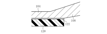
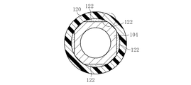
- the adhesive 122 plays a role in strengthening the bonding state of the base material (hollow shaft 102) and the FRP layer 120. If the bonding state between the base material and the FRP layer is poor, only the base material, that is, the intermediate shaft 102 receives torque, and the FRP layer 120 can not share torque, and the purpose of strengthening can not be achieved.
- FIG. 5A shows an example in which laser welding is performed between the hollow shaft 102 as the base material and the end of the FRP layer 120 at a plurality of places as indicated by reference numeral 124.
- the outer surface of the hollow shaft 102 may be subjected to a surface treatment 126.
- the surface treatment is a kind of roughening, and by increasing the surface area by providing a large number of irregularities on the surface on which the adhesive is interposed, the adhesive strength of the adhesive is enhanced. Shot blast and knurling can be mentioned as a specific example of such base treatment.
- the contour of the outer peripheral surface of the intermediate portion 104 (maximum diameter portion) of the hollow shaft 102 may be polygonal. Good. Although the case of a regular polygon is illustrated in the drawings, the regular polygon need not necessarily be used. As shown in FIG. 7A, a plurality of axial grooves may be provided on the outer peripheral surface of the intermediate portion 104 of the hollow shaft 102. In this case, in addition to the cross-sectional shape similar to serration as illustrated, it may be a spline or a concavo-convex shape similar to a gear.
- the middle portion 104 has a larger diameter than the connection portion 106, the middle portion 104 is the largest outer diameter portion of the hollow shaft 102.
- specific gravity of CFRP (assumed to be 60% of fiber volume content of resin) is 1.6 relative to specific gravity 7.9 of steel. The strength can not be generally stated because the strength of the carbon fiber is anisotropic, but the specific strength (tensile strength per unit density) is 60MPa for steel, whereas CFRP is 300MPa for the same weight. It will have double tensile strength.
- the winding angle of carbon fiber is set to 45 ° direction. Bending rigidity is improved by combining with a winding angle of 5 to 30 °.
- the 1 ° direction sheet-like CFRP may be wound around the outer periphery of the intermediate portion 104 of the hollow shaft 102 in advance. Thereby, the bending rigidity can be further improved.
- Carbon fibers are anisotropic in strength and differ in strength depending on the winding method. Basically, for twisting, wind in the 45 ° direction. Since the failure mode of the intermediate shaft is twisting, it is expected to strengthen against twisting by winding in the direction of 45 ° with respect to the axis.
- bending stiffness is enhanced by making the angle of the carbon fiber smaller than 45 ° with respect to the axis of the hollow shaft, and the tension is further strengthened, so bending stiffness can be selected by selecting a winding angle of 0 to 45 ° if necessary. Tensile rigidity can be improved.
- the molding length of the FRP pipe is an integral multiple of 2 or more of the fitting length L (FIG. 4) of the middle portion 104 of the hollow shaft 102 to be fitted, so that a plurality of FRP pipes can be made at one time Since molding is possible, the number of steps can be reduced.
- an FRP layer 120 is formed by directly winding a carbon fiber bundle impregnated with a resin or a carbon fiber formed into a sheet shape around a hollow shaft 102 made of steel. is there. In this case, since it is not necessary to form a separate CFRP pipe, the manufacturing efficiency can be improved.
- the cross-sectional shape of the hollow shaft 102 made of steel can be the same as that described above with reference to FIGS. 6 and 7.
- the angle ⁇ at which the carbon fibers are wound is preferably 45 ° with respect to the axial direction of the intermediate shaft.
- bending rigidity can be improved by winding the winding angles ⁇ and ⁇ in combination of the directions of 5 to 30 ° and 45 °.
- a 0 ° direction (axial direction of the intermediate shaft 102) is also possible.
- the intermediate shaft S1 is a composite of a steel member 210 and a CFRP member 220.
- the steel member 210 is hollow throughout its entire length, and the reference numeral 212 represents a hollow portion.
- the steel member 210 includes a central large diameter portion 214 and small diameter portions 216 at both ends, and the length of the large diameter portion 214 is indicated by a symbol L1.
- a serration shaft 218 is provided at the axial end of the small diameter portion 216.
- the CFRP member 220 is a CFRP formed into a pipe shape.
- the method of manufacturing the CFRP member 220 and the details of the material plastic are not particularly limited.
- a manufacturing method a filament winding method, a sheet winding method, a pultrusion process, a rolling method of a prepreg sheet, and the like are known.
- the type and winding angle of carbon fiber which is a reinforcing fiber are not particularly limited.
- the length L1 of the CFRP member 220 is approximately equal to the length L1 of the large diameter portion 214 of the steel member 210 described above.
- the CFRP member 220 has substantially the same diameter over the entire length, and a boot groove 222 for fitting a boot on the outer periphery of both ends is provided. By forming the boot groove 222 in the CFRP member 220, the small diameter portion 216 of the steel member 210 can be shortened and the large diameter portion 214 can be lengthened accordingly.
- the length L1 of the large diameter portion 214 of the steel member 210 and the length L1 of the CFRP member 220 are set longer than the length L of the large diameter portion of the conventional shaft S shown in FIG. (L1> L).
- the shaft S1 is lighter than the conventional shaft S and has high rigidity. That is, (1) Weight reduction can be achieved by thinning the large diameter portion 214 of the steel member 210 and reinforcing it with the CFRP member 220 (replacement of material).
- the compounding in which the steel member 210 and the CFRP member 220 in which the boot groove 222 is formed at both ends of the outer diameter are fitted can be implemented by various methods. As shown in FIG. 12, the steel member 210 and a CFRP member 220 formed in advance in a pipe shape may be joined by an adhesive 224. Further, as shown in FIG. 13, an adhesive reservoir 226 may be provided in order to enhance the adhesion by the adhesive. FIG. 13 shows an example in which the adhesive reservoir 226 is formed by the concave portion formed on the outer periphery of the large diameter portion 214 of the steel member 210. 12 and 13 are somewhat exaggerated with respect to the thickness of the adhesive layer and the depth of the adhesive reservoir 226.
- a rotational direction locking portion 230 may be provided on the outer periphery of the large diameter portion 214 of the steel member 210. Then, by pressing the steel member 210 into the CFRP member 220, the convex portion of the rotation direction locking portion 230 is bitten into the inner peripheral surface of the CFRP member 220 to be integrated.
- the rotational direction locking portion 230 may be disposed over the entire length of the large diameter portion 214 of the steel member 210, or may be disposed only at both ends as shown in FIG. 14A.
- the rotational direction locking portion 230 plays the role of interposing between the steel member 210 and the CFRP member 220 to prevent relative rotation, and serrations and splines can be mentioned as a representative example, but other similar shapes Can also be adopted. If the rotational direction locking portion 230 takes the form of serrations or splines, the teeth and grooves extend axially (FIG. 14A) and appear as a series of asperities as shown at 32 in the cross section (FIG. 14B).
- a knurled surface can be mentioned as another form of the rotational direction locking portion 230. That is, as shown in FIG. 15, in order to increase the bonding strength between steel member 210 and CFRP member 220, uneven surface 234 is formed on the outer peripheral surface of large diameter portion 214 of steel member 210 by knurling. The convex portion may be made to bite into the inner circumferential surface of the CFRP member 220.
- the boot groove 222 of the CFRP member 220 is formed by machining after heat curing of the CFRP member 220, or when heat curing the CFRP member 220, the die is pressed from the outer diameter side toward the axial center by pressing Depending on the situation, it may be baked at the same time.
- the steel member 210 may be formed by a filament winding method or a sheet winding method. A carbon fiber containing a resin or a sheet of a carbon fiber containing a resin may be directly wound, and then the steel member and the CFRP member may be composited by a thermal effect (curing).
- the CFRP member is shrunk by heat curing, whereby the inner diameter surface of the CFRP member 220 bites into the concavo-convex portion provided in the steel member 210, thereby being integrated.
- the boot groove is formed as described above.
- the shaft S1 for power transmission shaft affects the torsional rigidity by forming a CFRP member 220 which is shaped like a pipe by attaching boot grooves at both ends of the outer diameter surface and fitting it to the large diameter portion 214 of the steel member 210.
- the large diameter portion can be elongated in the axial direction, and high rigidity can be achieved.
- the boot groove 222 of the CFRP member 220 By forming the boot groove 222 of the CFRP member 220 by machining, the boot groove 222 can be easily formed into an arbitrary shape (advantage by machining).
- the adhesive reservoir 226 is provided on the outer periphery of the large diameter portion 214 of the steel member 210, so that a slight adhesive layer (see FIG. 13) existing between the steel member 210 and the CFRP member 220 temporarily extends in the radial direction. Even if the equal members are fitted in a biased state and the circumferentially discontinuous bonding state is achieved, the adhesive reservoir portion can be adhesively fixed on the entire circumferential surface regardless of the bias.
Landscapes
- Engineering & Computer Science (AREA)
- General Engineering & Computer Science (AREA)
- Ocean & Marine Engineering (AREA)
- Mechanical Engineering (AREA)
- Shafts, Cranks, Connecting Bars, And Related Bearings (AREA)
Abstract
ドライブシャフト用中間軸は、鋼製の中空軸(102)の外周にFRP層(120)を設けることにより軽量化と曲げ剛性の向上を図る。中空軸(102)は鋼製で、中間部(104)と、中間部(104)の両側の接続部(106)とからなり、全長にわたり中空で、中間部(104)の外周にFRP層(120)が設けてある。具体的には、パイプ状に成形したFRPを中空軸(102)の外周に嵌合させる、樹脂を含浸させた炭素繊維の束を中空軸(102)の外周に巻き付ける、シート状に成形したCFRPを中空軸(102)の外周に巻き付ける、といった態様がある。
Description
この発明は、自動車のドライブシャフト用中間軸に関する。
自動車のドライブシャフトは、中間軸とその両端に取り付けた等速自在継手とで構成され、自動車の駆動系に組み込み、非直線上に存在する回転軸同士の間で、回転力の伝達を行なう。例えば前輪駆動車の場合、エンジンと前輪との間に介在して動力を伝達する役割を果たす。従来、この中間軸には鋼製の中実軸が広く使用されていた。しかし、最近、燃費向上や静粛性向上が求められる中で、鋼製の中実軸を使用したドライブシャフトは、重量が重く、その割には剛性が低いことが原因となって、しばしば燃費向上のための軽量化や振動低減を目的とした高剛性化の要求が課せられている。そこで、中実軸に代えて中空軸が採用され始めている(特許文献1、2)。
特許文献1では、中間軸を中空にすることで振動特性の改善を達成することが提案されている。特許文献1から引用して説明すると、図1に四輪駆動の自動車の駆動系が概略示してあり、前置機関1によって変速機2および前軸差動装置3、さらに前部のドライブシャフト5を介して前輪4を駆動するようになっている。後輪6への駆動トルクは前軸差動装置3から分岐してプロペラシャフト7を経て後軸差動装置8へ伝わる。後軸差動装置8は後部のドライブシャフト9を介して後輪6を駆動する。
図2に、前部および後部のドライブシャフト5、9に用いられる中間軸の一例を示す。この中間軸Sは鋼製で、全長にわたって中空である。中間軸Sは中央部と、その両側に位置して中央部よりも小径の端部とからなり、符号Lは中央部の長さを表している。各端部にはセレーション(またはスプライン、以下同じ)軸が形成してあり、図示してない内側ジョイント部材のセレーション孔とトルク伝達可能に接続するようになっている。
図3は、中空の中間軸を用いたドライブシャフトの例である。このドライブシャフトは、中間軸Sと、中間軸Sの一方の端部に取り付けた固定式等速自在継手J1と、中間軸Sのもう一方の端部に取り付けたしゅう動式等速自在継手J2とで構成されている。
固定式等速自在継手J1は、原動軸と従動軸との間で角度変位のみ可能なタイプで、外輪11と、内輪12と、複数のボール13と、ケージ14とからなり、内輪12と中間軸S(原動軸)をトルク伝達可能に接続し、外輪11と駆動車輪のホイールハブ(従動軸)をトルク伝達可能に接続するようになっている。
しゅう動式等速自在継手J2は、原動軸と従動軸との間で角度変位だけでなく軸方向変位(プランジング)も可能なタイプで、ここではトリポード型が例示してある。トリポード型等速自在継手J2は、外輪21と、トリポード22と、ローラ23とからなり、外輪21をディファレンシャルの出力軸(原動軸)とトルク伝達可能に接続し、トリポード22を中間軸S(従動軸)とトルク伝達可能に接続するようになっている。
潤滑グリースの洩れや異物の進入を防止するため、蛇腹状のブーツ15、25を装着して使用するのが一般的である。車両に搭載した状態における位置関係から、固定式等速自在継手J1をアウトボードジョイント、しゅう動式等速自在継手J2をインボードジョイントと呼ぶこともある。なお、等速自在継手の詳細はすでによく知られており、また、この発明の要旨と直接関係するものではないため、ここでは省略する。
中実軸に代えて中空軸を採用することによる軽量化の効果は小さく、より軽量なドライブシャフトが求められるようになってきた。例えば、軽量化のために中央部を薄肉にすると必要強度が得られない。捩り剛性を確保するために中央部の外径を大きくし、かつ、肉厚を確保すると、所望の軽量効果が得られなくなる。また、中間軸にブーツを取り付けるための溝(ブーツ溝)を最小軸径部に設ける必要があることから、軽量化のために中央部の軸方向長さを長くするには限界があった。
この発明の課題は、ドライブシャフトを、強度を確保しつつ、一層軽量化することにある。
この発明は、中空軸の外周部分を繊維強化樹脂(以下、FRPという)で置換することによって課題を解決したものである。すなわち、この発明の一つの側面によれば、ドライブシャフト用中間軸は、中間軸とその両端に取り付けた等速自在継手とで構成されるドライブシャフトにおける中間軸であって、前記中間軸は、中間部と前記中間部の両側の接続部とからなり全長にわたって中空の中空軸と、前記中間部の外周に設けたFRP層とを有する。
FRP層の具体的な態様を例示するならば、パイプ状に成形したFRPを前記中空軸の前記中間部の外周に嵌合させたもの、樹脂を含浸させた炭素繊維の束を前記中空軸の前記中間部の外周に巻き付けたもの、シート状に成形した炭素繊維強化樹脂(CFRP)を前記中空軸の前記中間部の外周に巻き付けたものが挙げられる。
パイプ状に成形したFRPを前記中空軸の前記中間部の外周に嵌合させることによりFRP層を形成する場合、パイプ状に成形したFRPの成形長さを中空軸の中間部と嵌合させる長さLの2以上の整数倍としてもよい。中空軸の中間部との嵌合長さLの2以上の整数倍の長さを有するFRP製パイプを成形し、嵌合長さLに切断して使用するようにすれば、複数本分のFRP製パイプを一度に成形することができるため工数低減が図れる。
また、パイプ状に成形したFRPと中空軸の中間部との接合に接着剤を使用してもよい。この場合、例えばエポキシ系接着剤、ウレタン系接着剤を使用することができる。
樹脂を含浸させた炭素繊維の束を中空軸の中間部の外周に巻き付け、あるいは、シート状に成形した炭素繊維強化樹脂(CFRP)を中空軸の中間部の外周に巻き付けることによってFRP層を形成する場合、中空軸の軸線に対する炭素繊維の角度を45°としてもよい。炭素繊維は強度に異方性があり、巻き方によって強度が異なる。基本的に、捩れに対しては45°方向に巻く。中間軸の破損モードは捩れであるため、軸線に対して45°方向に巻くことで捩れに対する強化が期待できる。また、中空軸の軸線に対する炭素繊維の角度を45°より小さくすることで曲げ、引張りに対してはより強化されるため、必要に応じて0~45°の巻き角を選ぶことによって曲げ剛性、引張剛性を向上させることができる。
また、中空軸の軸線に対する炭素繊維の角度を0より大きく45°以下の任意の角度とし、2種類以上の角度を複合させてもよい。
中空軸とFRP層の回り止めをするため、中空軸の中間部の外周面の輪郭を多角形とし、あるいは、中空軸の中間部の外周面に軸方向の溝を設けてもよい。
接着剤を使用する、中空軸の中間部の外周面の輪郭を多角形とする、中空軸の中間部の外周面に軸方向の溝を設ける、といった構成は、それぞれ単独でも、任意に組み合わせても、実施することができる。
また、この発明のもう一つの側面によれば、ドライブシャフト用中間軸は、中央の大径部と両端の小径部とからなる中空の鋼部材と、鋼部材の大径部の外周にはめ合わせたCFRP部材との複合体で構成され、前記CFRP部材の外周面にブーツ溝を設けたものである。
パイプ状に成形したCFRP部材を鋼部材の大径部にはめ合わせてもよい。
CFRP部材のブーツ溝を機械加工により形成してもよい。
CFRP部材のブーツ溝をプレス加工により形成してもよい。
鋼部材とCFRP部材を接着剤により固定してもよい。
鋼部材の大径部の外周に接着剤溜まりを設けてもよい。
パイプ状CFRP部材と鋼部材を回転方向の係止部位を介して圧入固定してもよい。
前記回転方向係止部位を鋼部材の両端部に設けてもよい。
前記回転方向係止部位はセレーションまたはスプラインでもよい。
前記回転方向係止部位はローレット加工面でもよい。
この発明の一つの側面によれば、中間軸を構成する鋼製の中空軸の中間部の外周部分を軽量素材である繊維強化樹脂からなる層すなわちFRP層で置換することで、中間軸のさらなる軽量化が実現する。したがって、この発明によるドライブシャフト用中間軸を使用することにより、自動車の燃費向上と振動特性の向上を図ることができる。
この発明のもう一つの側面によれば、ドライブシャフト用中間軸を、軽量高強度素材であるCFRP(炭素繊維強化プラスチック)で成形したパイプ状のCFRP部材と、中空軸状の鋼部材とを複合化することで、強度低下することなくドライブシャフトの一層の軽量化を達成することができる。したがって、ドライブシャフトの軽量化を通じて車両の燃費向上に貢献することができる。
また、CFRP部材の外周にブーツ溝を形成することで、大径部(中央部)の軸方向長さをより長くすることが可能となる。したがって、大径部(中央部)の軸長大により得られる捩り剛性が向上し、当該ドライブシャフトを搭載した車両の振動特性の向上に寄与する。
また、CFRP部材の外周にブーツ溝を形成することで、大径部(中央部)の軸方向長さをより長くすることが可能となる。したがって、大径部(中央部)の軸長大により得られる捩り剛性が向上し、当該ドライブシャフトを搭載した車両の振動特性の向上に寄与する。
以下、図面に従ってこの発明の実施の形態を説明する。中間軸は鋼製の中空軸102とFRP層120とで構成されるが、まず中空軸102について述べる。
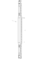
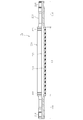
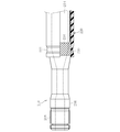
図4Aおよび図4Bに示すように、中空軸102は中間部104とその両側の、中間部104よりも小径の接続部106とからなり、全長にわたって中空である。中空軸102は、中間部104よりも大径のパイプ素材を冷間加工で縮径させることにより、中間部104と接続部106を一体的に形成してある。冷間加工によって加工硬化が付与される。
各接続部106は、中間部104側の端部(内端部)に形成したテーパ部108を介して中間部104と一体化させてある。各接続部106は、中間部104寄りの位置に、転造等によりブーツ取り付け溝110a、110bが形成してある。これはブーツの小径部を取り付ける部分である。また、各接続部106の先端部(外端部)には転造等によりセレーション112が形成してある。セレーション112の先端部(外端部)に止め輪溝114が形成してあり、セレーション112の終端部には膨出部116が形成してある。この膨出部116とブーツ取り付け溝110a、110bの間の部分118が接続部106において最も小径となっている。
図4Aに示す実施例は、上に述べた鋼製の中空軸102の中間部104の外周に、繊維強化樹脂の層すなわちFRP層120を設けたものである。言い換えれば、中間部104の最外層の鋼材をFRPに置換したものである。周知のとおりFRPは、炭素繊維やガラス繊維等の繊維で強化した樹脂からなる複合材料である。繊維強化材には、ガラス繊維、有機繊維、炭素繊維、金属繊維、無機繊維等がある。この実施例は、パイプ状に成形したFRP層120を中空軸102の中間部104の外周に嵌合させた例である。
中空軸102とFRP層120の接合には、接着剤122(図4C)やレーザ溶着124(図5A)を採用することができる。接着剤には例えばエポキシ系やウレタン系接着剤を使用することができる。接着剤122は母材(中空軸102)とFRP層120の接合状態を強固にする役割を果たす。母材とFRP層間の接合状態が悪いと、母材すなわち中間軸102のみがトルクを受けて、FRP層120がトルクを分担することができず、強化という目的が達成できなくなる。図5Aは、符号124で示すように、母材である中空軸102とFRP層120の端部との間を複数箇所でレーザ溶着した例を示す。
図5Bに示すように、中空軸102の母材とFRP層120との接着力を向上させるために、中空軸102の外周に下地処理126を施してもよい。ここでの下地処理は一種の粗面化であって、接着剤を介在させる表面に多数の凹凸を設けて表面積を増やすことにより、接着剤の接着力を増強するものである。そのような下地処理の具体例としては、ショットブラストやローレット加工を挙げることができる。
中空軸102とFRP層120との間の滑りによる強度低下を防止するため、図6Aに示すように、中空軸102の中間部104(最大径部)の外周面の輪郭を多角形にしてもよい。図面には正多角形の場合を例示したが、必ずしも正多角形である必要はない。図7Aに示すように、中空軸102の中間部104の外周面に軸方向の溝を複数設けてもよい。この場合、図示するようにセレーション類似の断面形状とするほか、スプラインあるいは歯車類似の凹凸形状としてもよい。
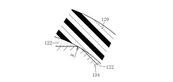
中間部104の外周面の輪郭を多角形にし、または軸方向溝を設ける場合、図6B、6Cおよび図7B、7Cに示すように、稜線部分に丸みを付けることにより、FRP層120に対する応力集中が緩和されるため、高強度を確保できる。
以上のように鋼製の中空軸102とFRP層120との複合体とすることで、軽量化と高強度の両立を図ることができる。また、すでに述べたとおり、接続部106よりも中間部104が大径であることから、中間部104が中空軸102の最大外径部分である。この最大外径部分の外周についてFRP層120による置換を行なうことにより、重量軽減、曲げ剛性向上といった効果を最大限引き出すことができる。比重で比較すると、鋼の比重7.9に対してCFRP(樹脂の繊維体積含有量60%と仮定)の比重は1.6である。強度は、炭素繊維の強度に異方性があるため一概には言えないが、比強度(単位密度当たりの引張強度)では鋼が60MPaであるのに対してCFRPは300MPaとなり、同じ重量では5倍の引張強度を持つことになる。
また、CFRP(炭素繊維強化樹脂)製パイプを成形する際、炭素繊維の巻き付け角度を45°方向とする。5~30°の巻き角と組み合わせることにより曲げ剛性が向上する。あらかじめ中空軸102の中間部104の外周に1°方向シート状CFRPを巻き付けておいてもよい。それにより、さらなる曲げ剛性向上を図ることができる。炭素繊維は強度に異方性があり、巻き方によって強度が異なる。基本的に、捩れに対しては45°方向に巻く。中間軸の破損モードは捩れであるため、軸線に対して45°方向に巻くことで捩れに対する強化が期待できる。また、中空軸の軸線に対する炭素繊維の角度を45°より小さくすることで曲げ、引張りに対してはより強化されるため、必要に応じて0~45°の巻き角を選ぶことによって曲げ剛性、引張剛性を向上させることができる。
FRP製パイプの成形長さは、嵌合する中空軸102の中間部104の嵌合長さL(図4)の2以上の整数倍とすることで、複数本分のFRP製パイプを一度に成形することができるため、工数低減が図れる。
次に、図8に示す実施例は、鋼製の中空軸102の外周に、樹脂を含浸させた炭素繊維の束またはシート状に成形した炭素繊維を直接巻き付けてFRP層120を形成したものである。この場合、別体のCFRP製パイプを成形する必要がないため、製造効率を改善できる。
鋼製の中空軸102の断面形状に関しては、図6および図7を参照して上に述べたのと同様とすることができる。炭素繊維を巻き付ける角度αは、中間軸の軸方向に対して45°方向が好ましい。
図9に示すように、巻き角βおよびγは、5~30°方向と45°方向を組み合わせて巻き付けることにより、曲げ剛性向上を図ることができる。シート状CFRPを巻き付ける場合には0°方向(中間軸102の軸方向)も可能である。
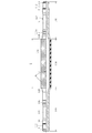
図10および図11に示すように、中間軸S1は鋼部材210とCFRP部材220を複合化したものである。鋼部材210は全長にわたり中空で、符号212は中空部を表している。鋼部材210は中央の大径部214と、両端の小径部216とからなり、大径部214の長さを符号L1で示してある。小径部216の軸端部にはセレーション軸218が設けてある。
CFRP部材220はCFRPをパイプ状に成形したものである。なお、ここでは、CFRP部材220の製造方法や材料プラスチックの詳細については特に限定するものではない。たとえば、製造方法としてはフィラメントワインディング法、シートワインディング法、引き抜き成形法(Pultrusion Process)、プリプレグシートのローリング成形法などが知られている。また、強化繊維たる炭素繊維の種類や巻き角度等についても特に限定するものではない。
CFRP部材220の長さL1は上に述べた鋼部材210の大径部214の長さL1とほぼ等しい。CFRP部材220は全長にわたってほぼ同径で、両端部の外周にブーツを嵌合させるためのブーツ溝222が設けてある。ブーツ溝222をCFRP部材220に形成することにより、鋼部材210の小径部216を短くしてその分だけ大径部214を長くすることができる。
このように、鋼部材210の大径部214の長さL1およびCFRP部材220の長さL1は、図2に示した従来のシャフトSの大径部の長さLよりも長く設定してある(L1>L)。このような構成を採用することで、シャフトS1は従来のシャフトSよりも軽量で、かつ、剛性の高いものとなる。すなわち、(1)鋼部材210の大径部214を薄肉にしてCFRP部材220で補強することにより(材料の置換)、軽量化が達成できる。(2)鋼部材210の全長のうち大径部214が占める割合を大きくすることにより(L1>L)、上記軽量化効果が一層助長されるばかりでなく、大径部(中央部)214が長くなったことにより得られる捩り剛性が向上し、当該動力伝達軸を搭載した車両の振動特性の向上に寄与する。
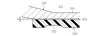
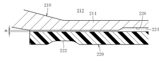
鋼部材210と外径両端部にブーツ溝222を成形したCFRP部材220を嵌め合わせる複合化は、種々の方法で実施することができる。図12に示すように、鋼部材210とあらかじめパイプ状に成形したCFRP部材220を接着剤224により接合してもよい。また、接着剤による密着性を高めるために、図13に示すように、接着剤溜まり226を設けてもよい。図13は、鋼部材210の大径部214の外周に形成した凹部によって接着剤溜まり226が形成された例を示している。なお、図12および図13は接着剤層の厚さや接着剤溜まり226の深さに関して幾分誇張してある。
図14Aおよび図14Bに示すように、鋼部材210とCFRP部材220の結合強度を増すために、鋼部材210の大径部214の外周に回転方向係止部位230を設けてもよい。そして、鋼部材210をCFRP部材220に圧入することにより、CFRP部材220の内周面に回転方向係止部位230の凸部を食い込ませて一体化する。回転方向係止部位230は、鋼部材210の大径部214の全長にわたって配置するほか、その一部分たとえば図14Aに示すように両端部にのみ配置してもよい。回転方向係止部位230は鋼部材210とCFRP部材220との間に介在して相対回転を阻止する役割を果たすもので、セレーションやスプラインが代表例として挙げられるが、その他の類似の形状のものを採用することもできる。回転方向係止部位230がセレーションまたはスプラインの形態をとる場合、歯と溝が軸方向に延在し(図14A)、横断面では符号32で示すように凹凸の連続として現われる(図14B)。
回転方向係止部位230の他の形態としてローレット加工面を挙げることができる。すなわち、図15に示すように、鋼部材210とCFRP部材220の結合強度を増すために、鋼部材210の大径部214の外周面にローレット加工により凹凸面234を成形し、凹凸面234の凸部をCFRP部材220の内周面に食い込ませるようにしてもよい。
CFRP部材220のブーツ溝222は、CFRP部材220の熱硬化後、機械加工により形成するか、あるいは、CFRP部材220を熱硬化させる際、外径側から軸心に向かってプレスにより金型を押し付けることにより、同時に焼き固めるようにしてもよい。
また、セレーションやスプライン、あるいは、ローレット成形による凹凸状の係止部を、鋼部材210の大径部214両端に成形する場合は、鋼部材210にフィラメントワインディング法 あるいは シートワインディング法 等の手法で、樹脂を含有させた炭素繊維 あるいは 樹脂を含有した炭素繊維のシートを直接巻き付け、その後、熱効果(キュア)させる方法で、鋼部材とCFRP部材を複合化させてもよい。この場合、熱硬化によりCFRP部材が収縮することで、鋼部材210に設けた凹凸部にCFRP部材220の内径面が食い込むことで一体化される。尚、ブーツ溝は、前述の如く形成する。
また、セレーションやスプライン、あるいは、ローレット成形による凹凸状の係止部を、鋼部材210の大径部214両端に成形する場合は、鋼部材210にフィラメントワインディング法 あるいは シートワインディング法 等の手法で、樹脂を含有させた炭素繊維 あるいは 樹脂を含有した炭素繊維のシートを直接巻き付け、その後、熱効果(キュア)させる方法で、鋼部材とCFRP部材を複合化させてもよい。この場合、熱硬化によりCFRP部材が収縮することで、鋼部材210に設けた凹凸部にCFRP部材220の内径面が食い込むことで一体化される。尚、ブーツ溝は、前述の如く形成する。
図10~15を参照して上に述べた実施の形態の効果は以下のとおりである。
動力伝達軸用シャフトS1は、外径面両端にブーツ溝を付帯しパイプ状に成形したCFRP部材220を鋼部材210の大径部214にはめ合わせた構造とすることにより、捩り剛性に影響する大径部を軸方向に向かって長くすることが可能となり、高剛性化を図ることができる。
CFRP部材220のブーツ溝222を機械加工で形成することにより、ブーツ溝222を任意の形状に成形しやすくなる(機械加工による利点)。
CFRP部材220のブーツ溝222をプレス加工で形成することにより、定常形状を成形する場合、切削加工が不要となるため低コスト化を図ることができる。
鋼部材210とCFRP部材220を接着剤224で固定することにより、鋼部材210とCFRP部材220の結合強度が増す。
鋼部材210の大径部214の外周に接着剤溜まり226を設けることで、鋼部材210とCFRP部材220の間に存在する僅かな接着剤層(図13参照)により、仮に、径方向にこれ等部材が偏った状態で嵌合され、円周上不連続な接着状態になったとしても、接着剤溜りの部分は偏りに関係なく円周上全面接着固定することができる。
パイプ状CFRP部材220と鋼部材210を回転方向係止部位を介して圧入することにより、鋼部材210とCFRP部材220の結合強度が一層増す。
回転方向係止部位を鋼部材210の両端部に設けることにより、シャフトが捩られた状態で、複合化された部位の最も負荷がかかる場所を確実に固定することができる。
前記回転方向係止部位を、セレーションまたはスプラインあるいは ローレット加工による凹凸形状とすることで、機械加工による鋼部材210への成形性が容易となる。
102 中空軸
104 中間部
106 接続部
108 テーパ部
110a、110b ブーツ取り付け溝
112 スプライン
114 止め輪溝
116 膨出部
118 最小径部分
120 FRP層
122 接着剤
124 レーザ溶着
126 下地処理
S1 中間軸
210 鋼部材
212 中空部
214 大径部
216 小径部
218 セレーション軸
220 CFRP部材
222 ブーツ溝
224 接着剤
226 接着剤溜まり
230 回転方向係止部位
232 セレーション軸
234 ローレット加工面
104 中間部
106 接続部
108 テーパ部
110a、110b ブーツ取り付け溝
112 スプライン
114 止め輪溝
116 膨出部
118 最小径部分
120 FRP層
122 接着剤
124 レーザ溶着
126 下地処理
S1 中間軸
210 鋼部材
212 中空部
214 大径部
216 小径部
218 セレーション軸
220 CFRP部材
222 ブーツ溝
224 接着剤
226 接着剤溜まり
230 回転方向係止部位
232 セレーション軸
234 ローレット加工面
Claims (20)
- 中間軸とその両端に取り付けた等速自在継手とで構成されるドライブシャフトにおける中間軸であって、前記中間軸は、中間部と前記中間部の両側の接続部とからなり全長にわたって中空の中空軸と、前記中間部の外周に設けた繊維強化樹脂層とを有する、ドライブシャフト用中間軸。
- パイプ状に成形した繊維強化樹脂を前記中空軸の前記中間部の外周に嵌合させた請求項1のドライブシャフト用中間軸。
- パイプ状に成形した繊維強化樹脂の成形長さを前記中空軸に嵌合させる必要長さの倍数とした請求項2のドライブシャフト用中間軸。
- パイプ状に成形した繊維強化樹脂と前記中空軸との接合に接着剤を使用した請求項2または3のドライブシャフト用中間軸。
- 樹脂を含浸させた炭素繊維の束を前記中空軸の前記中間部の外周に巻き付けた請求項1のドライブシャフト用中間軸。
- シート状に成形した炭素繊維強化樹脂を前記中空軸の前記中間部の外周に巻き付けた請求項1のドライブシャフト用中間軸。
- 前記中空軸の軸線に対する炭素繊維の角度を45°とした請求項5または6のドライブシャフト用中間軸。
- 前記中空軸の軸線に対する炭素繊維の角度を0より大きく45°以下の任意の角度とし、2種類以上の角度を複合した請求項5または6のドライブシャフト用中間軸。
- 前記中空軸の前記中間部の外周面の輪郭を多角形とした請求項1から6のいずれか1項のドライブシャフト用中間軸。
- 前記中空軸の前記中間部の外周面に軸方向の溝を設けた請求項1から7のいずれか1項のドライブシャフト用中間軸。
- 前記中間軸は、中央の大径部と両端の小径部とからなる中空の鋼部材と、鋼部材の大径部の外周にはめ合わせたCFRP部材との複合体で構成され、前記CFRP部材の外周面にブーツ溝を設けた請求項1のドライブシャフト用中間軸。
- パイプ状に成形したCFRP部材を鋼部材の大径部にはめ合わせた請求項11のドライブシャフト用中間軸。
- CFRP部材のブーツ溝を機械加工により形成した請求項11または12のドライブシャフト用中間軸。
- CFRP部材のブーツ溝をプレス加工により形成した請求項11または12のドライブシャフト用中間軸。
- 鋼部材とCFRP部材を接着剤により固定した請求項11~14のいずれか1項のドライブシャフト用中間軸。
- 鋼部材の大径部の外周に接着剤溜まりを設けた請求項11~15のいずれか1項のドライブシャフト用中間軸。
- パイプ状CFRP部材に鋼部材を回転方向係止部位を介して圧入した請求項11~14のいずれか1項のドライブシャフト用中間軸。
- 前記回転方向係止部位を鋼部材の大径部の両端部に設けた請求項17のドライブシャフト用中間軸。
- 前記回転方向係止部位はセレーションまたはスプラインである請求項17または18のドライブシャフト用中間軸。
- 前記回転方向係止部位はローレット加工面である請求項17または18のドライブシャフト用中間軸。
Applications Claiming Priority (4)
| Application Number | Priority Date | Filing Date | Title |
|---|---|---|---|
| JP2009-095784 | 2009-04-10 | ||
| JP2009095784A JP2010249145A (ja) | 2009-04-10 | 2009-04-10 | ドライブシャフト用中間軸 |
| JP2009-163716 | 2009-07-10 | ||
| JP2009163716A JP2011017413A (ja) | 2009-07-10 | 2009-07-10 | 動力伝達軸用シャフト |
Publications (1)
| Publication Number | Publication Date |
|---|---|
| WO2010116883A1 true WO2010116883A1 (ja) | 2010-10-14 |
Family
ID=42936169
Family Applications (1)
| Application Number | Title | Priority Date | Filing Date |
|---|---|---|---|
| PCT/JP2010/054810 Ceased WO2010116883A1 (ja) | 2009-04-10 | 2010-03-19 | ドライブシャフト用中間軸 |
Country Status (1)
| Country | Link |
|---|---|
| WO (1) | WO2010116883A1 (ja) |
Cited By (3)
| Publication number | Priority date | Publication date | Assignee | Title |
|---|---|---|---|---|
| EP2530339A1 (de) * | 2011-06-01 | 2012-12-05 | Technische Universität Darmstadt | Hohlwellenabschnitt für eine Antriebswelle aus einem Faserverbundwerkstoff |
| CN108161348A (zh) * | 2017-12-13 | 2018-06-15 | 宁波市海园毅超轴业有限公司 | 一种电动工具轴及其制备工艺 |
| CN108626237A (zh) * | 2018-07-16 | 2018-10-09 | 淄博朗达复合材料有限公司 | 一种碳纤维复合传动轴及其加工方法 |
Citations (3)
| Publication number | Priority date | Publication date | Assignee | Title |
|---|---|---|---|---|
| JPS558286U (ja) * | 1978-07-04 | 1980-01-19 | ||
| JPH0557425U (ja) * | 1991-12-27 | 1993-07-30 | いすゞ自動車株式会社 | 車両用プロペラシャフト |
| JP2001047883A (ja) * | 1999-08-05 | 2001-02-20 | Ntn Corp | 動力伝達シャフト |
-
2010
- 2010-03-19 WO PCT/JP2010/054810 patent/WO2010116883A1/ja not_active Ceased
Patent Citations (3)
| Publication number | Priority date | Publication date | Assignee | Title |
|---|---|---|---|---|
| JPS558286U (ja) * | 1978-07-04 | 1980-01-19 | ||
| JPH0557425U (ja) * | 1991-12-27 | 1993-07-30 | いすゞ自動車株式会社 | 車両用プロペラシャフト |
| JP2001047883A (ja) * | 1999-08-05 | 2001-02-20 | Ntn Corp | 動力伝達シャフト |
Cited By (4)
| Publication number | Priority date | Publication date | Assignee | Title |
|---|---|---|---|---|
| EP2530339A1 (de) * | 2011-06-01 | 2012-12-05 | Technische Universität Darmstadt | Hohlwellenabschnitt für eine Antriebswelle aus einem Faserverbundwerkstoff |
| CN108161348A (zh) * | 2017-12-13 | 2018-06-15 | 宁波市海园毅超轴业有限公司 | 一种电动工具轴及其制备工艺 |
| CN108161348B (zh) * | 2017-12-13 | 2019-12-17 | 博思韦精密工业(宁波)有限公司 | 一种电动工具轴及其制备工艺 |
| CN108626237A (zh) * | 2018-07-16 | 2018-10-09 | 淄博朗达复合材料有限公司 | 一种碳纤维复合传动轴及其加工方法 |
Similar Documents
| Publication | Publication Date | Title |
|---|---|---|
| JP6310489B2 (ja) | ドライブシャフト及びその製造方法 | |
| US20090215543A1 (en) | Slip yoke with internal splines having permanent coating and related method | |
| JP2003004060A (ja) | 継手及び動力伝達シャフト並びに継手の製造方法 | |
| CN102472310A (zh) | Frp制驱动轴 | |
| US20130252749A1 (en) | Propshafts and propshaft assemblies and methods for fabricating propshafts | |
| JP2011017413A (ja) | 動力伝達軸用シャフト | |
| JP2010249145A (ja) | ドライブシャフト用中間軸 | |
| CN109869417B (zh) | 具有等速万向节的铝制传动轴 | |
| WO2010116883A1 (ja) | ドライブシャフト用中間軸 | |
| JP2011017414A (ja) | 動力伝達軸用シャフト | |
| JP4245106B2 (ja) | 等速ジョイント用スプラインシャフトの製造方法および嵌合構造 | |
| US11428271B2 (en) | Rotational driving force transmission mechanism | |
| KR101999277B1 (ko) | 자동차용 cfrp 프로펠러샤프트 | |
| WO2019131549A1 (ja) | 動力伝達シャフト | |
| US20050043105A1 (en) | Propeller shaft | |
| CN113942248A (zh) | 一种复合材料传动轴的制作方法及其复合材料传动轴 | |
| US7543895B2 (en) | Metal-sheathed composite vehicle axle | |
| WO2019035395A1 (ja) | 動力伝達用シャフト | |
| US12123460B2 (en) | Power transmission shaft | |
| JPH04140514A (ja) | 動力伝達軸およびその製造方法 | |
| JP2958894B2 (ja) | 動力伝達軸 | |
| KR101073093B1 (ko) | 자동차 프로펠러 샤프트 연결구조 | |
| JPS6244168Y2 (ja) | ||
| JP2006103032A (ja) | Frp製円筒体と金属製継ぎ手との接合体 | |
| KR101484909B1 (ko) | 자동차용 복합소재 프로펠러샤프트 |
Legal Events
| Date | Code | Title | Description |
|---|---|---|---|
| 121 | Ep: the epo has been informed by wipo that ep was designated in this application |
Ref document number: 10761583 Country of ref document: EP Kind code of ref document: A1 |
|
| NENP | Non-entry into the national phase |
Ref country code: DE |
|
| 122 | Ep: pct application non-entry in european phase |
Ref document number: 10761583 Country of ref document: EP Kind code of ref document: A1 |