WO2010116459A1 - プレート式熱交換器、プレート式熱交換器の製造方法、プレート式熱交換器の積層判定装置及びプレート式熱交換器の積層判定方法 - Google Patents
プレート式熱交換器、プレート式熱交換器の製造方法、プレート式熱交換器の積層判定装置及びプレート式熱交換器の積層判定方法 Download PDFInfo
- Publication number
- WO2010116459A1 WO2010116459A1 PCT/JP2009/056534 JP2009056534W WO2010116459A1 WO 2010116459 A1 WO2010116459 A1 WO 2010116459A1 JP 2009056534 W JP2009056534 W JP 2009056534W WO 2010116459 A1 WO2010116459 A1 WO 2010116459A1
- Authority
- WO
- WIPO (PCT)
- Prior art keywords
- plate
- heat exchanger
- image information
- plates
- heat transfer
- Prior art date
- Legal status (The legal status is an assumption and is not a legal conclusion. Google has not performed a legal analysis and makes no representation as to the accuracy of the status listed.)
- Ceased
Links
Images









Classifications
-
- F—MECHANICAL ENGINEERING; LIGHTING; HEATING; WEAPONS; BLASTING
- F28—HEAT EXCHANGE IN GENERAL
- F28D—HEAT-EXCHANGE APPARATUS, NOT PROVIDED FOR IN ANOTHER SUBCLASS, IN WHICH THE HEAT-EXCHANGE MEDIA DO NOT COME INTO DIRECT CONTACT
- F28D9/00—Heat-exchange apparatus having stationary plate-like or laminated conduit assemblies for both heat-exchange media, the media being in contact with different sides of a conduit wall
- F28D9/0031—Heat-exchange apparatus having stationary plate-like or laminated conduit assemblies for both heat-exchange media, the media being in contact with different sides of a conduit wall the conduits for one heat-exchange medium being formed by paired plates touching each other
- F28D9/0043—Heat-exchange apparatus having stationary plate-like or laminated conduit assemblies for both heat-exchange media, the media being in contact with different sides of a conduit wall the conduits for one heat-exchange medium being formed by paired plates touching each other the plates having openings therein for circulation of at least one heat-exchange medium from one conduit to another
- F28D9/005—Heat-exchange apparatus having stationary plate-like or laminated conduit assemblies for both heat-exchange media, the media being in contact with different sides of a conduit wall the conduits for one heat-exchange medium being formed by paired plates touching each other the plates having openings therein for circulation of at least one heat-exchange medium from one conduit to another the plates having openings therein for both heat-exchange media
-
- F—MECHANICAL ENGINEERING; LIGHTING; HEATING; WEAPONS; BLASTING
- F28—HEAT EXCHANGE IN GENERAL
- F28F—DETAILS OF HEAT-EXCHANGE AND HEAT-TRANSFER APPARATUS, OF GENERAL APPLICATION
- F28F3/00—Plate-like or laminated elements; Assemblies of plate-like or laminated elements
- F28F3/02—Elements or assemblies thereof with means for increasing heat-transfer area, e.g. with fins, with recesses, with corrugations
- F28F3/04—Elements or assemblies thereof with means for increasing heat-transfer area, e.g. with fins, with recesses, with corrugations the means being integral with the element
- F28F3/042—Elements or assemblies thereof with means for increasing heat-transfer area, e.g. with fins, with recesses, with corrugations the means being integral with the element in the form of local deformations of the element
- F28F3/046—Elements or assemblies thereof with means for increasing heat-transfer area, e.g. with fins, with recesses, with corrugations the means being integral with the element in the form of local deformations of the element the deformations being linear, e.g. corrugations
-
- G—PHYSICS
- G01—MEASURING; TESTING
- G01N—INVESTIGATING OR ANALYSING MATERIALS BY DETERMINING THEIR CHEMICAL OR PHYSICAL PROPERTIES
- G01N21/00—Investigating or analysing materials by the use of optical means, i.e. using sub-millimetre waves, infrared, visible or ultraviolet light
- G01N21/84—Systems specially adapted for particular applications
- G01N21/88—Investigating the presence of flaws or contamination
- G01N21/95—Investigating the presence of flaws or contamination characterised by the material or shape of the object to be examined
-
- G—PHYSICS
- G01—MEASURING; TESTING
- G01N—INVESTIGATING OR ANALYSING MATERIALS BY DETERMINING THEIR CHEMICAL OR PHYSICAL PROPERTIES
- G01N21/00—Investigating or analysing materials by the use of optical means, i.e. using sub-millimetre waves, infrared, visible or ultraviolet light
- G01N21/84—Systems specially adapted for particular applications
- G01N21/88—Investigating the presence of flaws or contamination
- G01N21/95—Investigating the presence of flaws or contamination characterised by the material or shape of the object to be examined
- G01N21/956—Inspecting patterns on the surface of objects
- G01N21/95684—Patterns showing highly reflecting parts, e.g. metallic elements
-
- G—PHYSICS
- G06—COMPUTING OR CALCULATING; COUNTING
- G06T—IMAGE DATA PROCESSING OR GENERATION, IN GENERAL
- G06T7/00—Image analysis
- G06T7/0002—Inspection of images, e.g. flaw detection
- G06T7/0004—Industrial image inspection
- G06T7/001—Industrial image inspection using an image reference approach
-
- F—MECHANICAL ENGINEERING; LIGHTING; HEATING; WEAPONS; BLASTING
- F28—HEAT EXCHANGE IN GENERAL
- F28F—DETAILS OF HEAT-EXCHANGE AND HEAT-TRANSFER APPARATUS, OF GENERAL APPLICATION
- F28F2200/00—Prediction; Simulation; Testing
-
- F—MECHANICAL ENGINEERING; LIGHTING; HEATING; WEAPONS; BLASTING
- F28—HEAT EXCHANGE IN GENERAL
- F28F—DETAILS OF HEAT-EXCHANGE AND HEAT-TRANSFER APPARATUS, OF GENERAL APPLICATION
- F28F2280/00—Mounting arrangements; Arrangements for facilitating assembling or disassembling of heat exchanger parts
- F28F2280/04—Means for preventing wrong assembling of parts
-
- G—PHYSICS
- G06—COMPUTING OR CALCULATING; COUNTING
- G06T—IMAGE DATA PROCESSING OR GENERATION, IN GENERAL
- G06T2207/00—Indexing scheme for image analysis or image enhancement
- G06T2207/30—Subject of image; Context of image processing
- G06T2207/30108—Industrial image inspection
- G06T2207/30164—Workpiece; Machine component
Definitions
- the present invention relates to a technique for determining whether or not a plate stacking arrangement is correct in a plate heat exchanger formed by stacking a plurality of plates, for example.
- Patent Document 1 a plate-type heat exchanger is formed using a heat transfer plate provided with a notch in the outer edge, and it is determined whether or not the stacking arrangement of the heat transfer plates is correct based on the notch arrangement.
- JP-A-9-89484 JP-A-9-89484
- An object of the present invention is to make it possible to determine whether or not the heat transfer plate stacking arrangement is correct by using a photographing device such as a camera.
- the plate heat exchanger according to the present invention is, for example, It is a plate heat exchanger formed by laminating a plurality of plates, Each plate of the plurality of plates includes A protruding portion protruding in the stacking direction in which the plurality of plates are stacked is formed at a predetermined position on the outer edge of the plate.
- the protrusion is formed by bending a protrusion protruding outward from an outer edge of the plate in the stacking direction.
- the protruding portion is formed so as to be distinguishable from other portions in image information obtained by photographing the plate heat exchanger with a photographing device from the surface direction of the plate.
- the plate heat exchanger is formed by brazing the outer edge of each plate.
- the plate heat exchanger is formed by laminating a plurality of types of plates,
- the protrusions may be formed at different positions depending on the type of plate.
- the manufacturing method of the plate heat exchanger according to the present invention is, for example, Forming a plurality of plates having protrusions protruding outside the outer edge portion at predetermined positions of the outer edge portion; Bending the protrusions of each of the plurality of formed plates in a direction perpendicular to the surface of the plates; The plates are stacked by overlapping the surfaces of the plates.
- the plate type heat exchanger lamination judgment device is, for example, It is image information of a plate heat exchanger formed by laminating a plurality of plates, and is provided at the outer edge portion of each plate of the plurality of plates, and protrudes in the laminating direction in which the plurality of plates are laminated
- An image information acquisition unit for acquiring image information of a part by an imaging device;
- An image information storage unit for storing predetermined image information in a storage device;
- the laminated arrangement of the plates of the plate heat exchanger indicated by the image information acquired by the image information acquisition unit by comparing the image information acquired by the image information acquisition unit with the image information stored by the image information storage unit And a stacking determination unit that determines whether or not is correct by a processing device.
- the stacking determination unit specifies the cause of the incorrect stacking arrangement of the plates based on the arrangement of the protrusions in the image information acquired by the image information acquisition unit.
- the plate type heat exchanger lamination judgment method is, for example,
- the imaging apparatus is image information of a plate heat exchanger formed by laminating a plurality of plates, provided in an outer edge portion of each plate of the plurality of plates, and a laminating direction in which the plurality of plates are laminated
- the processing device compares the image information acquired in the image information acquisition step with the image information stored in the storage device in advance, and the plate of the plate heat exchanger indicated by the image information acquired in the image information acquisition step And a stack determination step for determining whether the stack arrangement is correct.
- the plate heat exchanger according to the present invention is formed by laminating a plate in which a protruding portion protruding in the stacking direction is formed on the outer edge portion. Therefore, it is possible to determine whether or not the stacking arrangement is correct by detecting the arrangement of the protrusions with a camera.
- Embodiment 1 FIG. First, (1) the structure of the plate heat exchanger will be described. Next, (2) the stacking determination apparatus 20 that determines whether or not the stacking arrangement of the heat transfer plates in the plate heat exchanger is correct will be described.
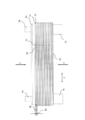
- FIG. 1 is a front view of the plate heat exchanger 10.
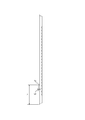
- FIG. 2 is a side view of the plate heat exchanger 10.
- the internal structure is indicated by a broken line. That is, the part shown with the broken line in FIG. 1 is a structure which cannot actually be seen from the front.
- the plate heat exchanger 10 a plurality of heat transfer plates 1a and heat transfer plates 1b are alternately stacked. That is, the plate heat exchanger 10 includes two different heat transfer plates 1a and 1b.
- a first flow path through which the first fluid flows and a second flow path through which the second fluid flows are formed between the heat transfer plate 1a and the heat transfer plate 1b. The first fluid flowing through the first flow path and the second fluid flowing through the second flow path are heat-exchanged via the heat transfer plates 1a and 1b without being mixed.
- a reinforcing frame 2a is stacked on one end side (A side in FIG. 2) in the stacking direction in which the heat transfer plates 1a and 1b are stacked.
- a reinforcing frame 2b is stacked on the other end side (B side in FIG. 2) in the stacking direction in which the heat transfer plates 1a and 1b are stacked.
- the reinforcing frame 2a includes a pipe joint 3a connected to the inlet 4a (see FIGS. 3 and 6) into which the first fluid flows, and a pipe joint 3b connected to the outlet 5a (see FIGS. 3 and 6) from which the first fluid flows out. Is provided.
- the reinforcing frame 2b includes a pipe joint 3c connected to the inlet 4b (see FIGS. 3 and 6) into which the second fluid flows and a pipe joint connected to the outlet 5b (see FIGS. 3 and 6) from which the second fluid flows out. 3d.
- the reinforcing frames 2a and 2b are provided to maintain the strength of the plate heat exchanger 10.
- the heat transfer plates 1a and 1b and the reinforcing frames 2a and 2b are permanently coupled by brazing. Thereby, the 1st fluid and the 2nd fluid which flow through the 1st flow path and the 2nd flow path formed between heat transfer plate 1a and heat transfer plate 1b do not leak outside from each flow path. It becomes a structure. That is, the outer edge portions 6 of the heat transfer plates 1a and 1b are brazed and sealed.
- the heat transfer plates 1a and 1b are made of stainless steel, aluminum or the like. On the other hand, for example, copper is used for the wax.
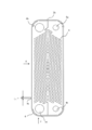
- FIG. 3 is a front view of the heat transfer plate 1a.
- FIG. 4 is a side view of the heat transfer plate 1a (viewed from the direction C in FIG. 3).
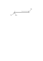
- FIG. 5 is a bottom view of the heat transfer plate 1a (viewed from the direction D in FIG. 3).
- FIG. 6 is a front view of the heat transfer plate 1b.
- FIG. 7 is a side view of the heat transfer plate 1b (viewed from the direction E in FIG. 6).
- FIG. 8 is a bottom view of the heat transfer plate 1b (viewed from the direction F in FIG. 6).
- the heat transfer plate 1a is formed with an inlet 4a, an outlet 5a, an inlet 4b, and an outlet 5b in the vicinity of four corners (corners).
- the heat transfer plate 1a has a plurality of concave portions and convex portions (concave / convex waveform 8) arranged in the longitudinal direction.
- the concavo-convex waveform 8 has both end portions on both ends in the short direction, and has a turning point at a position shifted from the both ends in the longitudinal direction. Thereby, the uneven
- the uneven waveform 8 is formed on almost the entire surface of the heat transfer plate 1a.
- the uneven waveform 8 is provided to promote heat exchange between the first fluid and the second fluid. Further, the heat transfer plate 1a is formed with a protruding portion 7a (cut and raised) at a predetermined position of the outer edge portion 6 (outer peripheral portion).
- the protruding portion 7a is formed to protrude in a direction orthogonal to the surface of the heat transfer plate 1a. That is, the protrusion 7a is formed to protrude in the direction in which the heat transfer plates 1a are stacked.
- the protruding portion 7a is formed by bending a protrusion protruding outward from the outer edge portion 6 of the heat transfer plate 1a in a direction perpendicular to the surface of the heat transfer plate 1a.
- the protruding portion 7 a is formed by being bent toward the side where the reinforcing frame 2 b is stacked in the stacking direction.
- the heat transfer plate 1b has substantially the same configuration as the heat transfer plate 1a. That is, as shown in FIGS. 6 to 8, the heat transfer plate 1b is formed with the inlet 4a, the outlet 5a, the inlet 4b, and the outlet 5b in the vicinity of the four corners.
- a plurality of uneven waveforms 8 are arranged in the longitudinal direction on the heat transfer plate 1b.
- the concavo-convex waveform 8 has both end portions at both ends in the short direction, and has a turning point at a position shifted from the both ends in the longitudinal direction. Thereby, the uneven
- the heat transfer plate 1 b is formed with a protruding portion 7 b (cut and raised) at a predetermined position of the outer edge portion 6.
- the protrusion part 7b is formed in the predetermined position of the outer edge part 6 of the longitudinal direction of the heat exchanger plate 1b.
- the protruding portion 7b is formed to protrude in a direction orthogonal to the surface of the heat transfer plate 1b.
- the protruding portion 7b is formed by bending a protrusion protruding outward from the outer edge portion 6 of the heat transfer plate 1b in a direction orthogonal to the surface of the heat transfer plate 1b.
- the protruding portion 7 b is formed by being bent toward the side on which the reinforcing frame 2 b is stacked in the stacking direction.
- the protrusion part 7b is formed in the outer edge part 6 used as the same side surface as the outer edge part 6 in which the protrusion part 7a was formed, when the heat-transfer plates 1a and 1b are correctly laminated
- projecting portions 7a and 7b are formed on the long side where the inflow hole 4b and the outflow hole 5b are formed. Therefore, as shown in FIG. 2, on the predetermined side surface of the plate heat exchanger 10 in which the heat transfer plates 1a and 1b are correctly stacked, the protrusions 7a and 7b formed on all the heat transfer plates 1a and 1b. Is placed.
- the concave / convex waveform 8 formed on the heat transfer plate 1a and the concave / convex waveform 8 formed on the heat transfer plate 1b have opposite V-shaped directions. That is, in the heat transfer plate 1a, the concave and convex waveform 8 is formed in a V shape having a turning point on the lower side in the longitudinal direction from both ends, whereas in the heat transfer plate 1b, the turning point on the upper side in the longitudinal direction from both ends.
- the concave-convex waveform 8 is formed in a V-shape (inverted V-shape) having Therefore, when the heat transfer plates 1a and 1b are stacked, as shown in FIG. 1, the concavo-convex waveform 8 formed in the opposite direction intersects. Thereby, a flow path with good heat transfer efficiency is formed.
- the length L1 (FIG. 4) from the longitudinal end of the heat transfer plate 1a to the protrusion 7a and the length L2 (FIG. 7) from the longitudinal end of the heat transfer plate 1b to the protrusion 7b are as follows. , The length is different. Therefore, as shown in FIGS. 1 and 2, when the heat transfer plates 1a and 1b are stacked, the protrusion 7a and the protrusion 7b are in the longitudinal direction of the heat transfer plates 1a and 1b (direction C in FIG. 2). The position is shifted to Here, the difference between the length L1 and the length L2 (the absolute value of L1-L2) is the length L3 in the longitudinal direction of the protrusion 7a (FIG.
- the length L5 (FIG. 4) of the protruding portion 7a in the stacking direction and the length L6 (FIG. 7) of the protruding portion 7b in the stacking direction are the heat transfer plates when the heat transfer plates 1a and 1b are stacked. It is shorter than the sum (W1 + W2) of the widths W1 and W2 (FIG. 2) between 1a and 1b.
- W1 and W2 are substantially the same
- L5 and L6 are shorter than double W1 (or double W2). Therefore, as shown in FIG. 2, when the heat transfer plates 1a and 1b are alternately stacked, the protruding portions 7a and the protruding portions 7b do not contact the protruding portions 7a and 7b of other plates.
- L5 and L6 may be shorter than the widths W1 and W2. In this case, even if the same heat transfer plate 1a is mistakenly stacked continuously, the two protruding portions 7a do not overlap in the surface direction.
- the protruding portions 7a and 7b are formed by bending the protrusions protruding outward of the outer edge portion 6 in a direction perpendicular to the surfaces of the heat transfer plates 1a and 1b.
- the angles ⁇ 1 and ⁇ 2 (FIGS. 5 and 8) for bending the protrusions are approximately 90 degrees.
- the angles ⁇ 1 and ⁇ 2 (FIGS. 5 and 8) for bending the protrusions may be larger or smaller than 90 degrees.
- FIG. 9 is an explanatory diagram of a process for determining whether or not the stacked arrangement of the heat transfer plates 1a and 1b in the plate heat exchanger 10 is correct.
- the outer edge portion 6 of the plate heat exchanger 10 is photographed by a photographing device provided in the lamination determination device 20.
- the imaging device is, for example, a camera 916.
- the stack determination device 20 photographs the surface of the plate heat exchanger 10 on which the protrusions 7a and 7b are formed from the plate surface direction.
- the lamination determination device 20 compares image information acquired by photographing with image information stored in advance, and determines whether or not the arrangement of the heat transfer plates 1a and 1b in the plate heat exchanger 10 is correct.
- FIG. 10 is a functional block diagram illustrating functions of the stack determination device 20.
- the stack determination device 20 includes an image information acquisition unit 21, an image information storage unit 22, and a stack determination unit 23.
- the image information acquisition unit 21 acquires image information of the outer edge portion 6 of the plate heat exchanger 10 using an imaging device (image information acquisition step). In particular, the image information acquisition unit 21 acquires image information of the entire portion where the protrusions 7a and 7b are formed. That is, the image information acquisition unit 21 acquires image information of the pattern formed by the protrusions 7a and 7b.
- the image information storage unit 22 stores image information of a predetermined pattern in a storage device in advance.
- the image information storage unit 22 stores image information of a pattern formed by the protrusions 7a and 7b when correctly stacked as shown in FIG.
- the stack determination unit 23 compares the image information (captured image) acquired by the image information acquisition unit 21 and the image information (stored image) stored by the image information storage unit 22 using a processing device. And the lamination
- the stack determination unit 23 determines that the stack arrangement of the heat transfer plates 1a and 1b of the plate heat exchanger 10 indicated by the captured image is correct. On the other hand, if the degree of coincidence between the captured image and the stored image is low, the stack determination unit 23 determines that the stack arrangement of the heat transfer plates 1a and 1b of the plate heat exchanger 10 indicated by the captured image is not correct. For example, the stack determination unit 23 quantifies and determines the relative positions of the protrusions 7a and 7b and the number of the protrusions 7a and 7b.
- the heat transfer plates 1a and 1b of the plate heat exchanger 10 are brazed.
- the outer edge portions 6 of the heat transfer plates 1a and 1b are also brazed.
- the protrusions 7a and 7b are not brazed.
- a metal different from the heat transfer plates 1a and 1b is used. Accordingly, the brazed portion is different in color and gloss from the non-brazed portion. That is, the protrusions 7a and 7b and the outer edge 6 of the heat transfer plates 1a and 1b have different colors and gloss. In particular, the normally brazed portion loses gloss.
- the protruding portions 7a and 7b and the portions other than the protruding portions 7a and 7b are clearly distinguished and can be easily identified. That is, in the photographed image, the protruding portions 7a and 7b are bright and have a bright color (white), whereas the portions other than the protruding portions 7a and 7b are not glossy and have a dark color (black).
- FIG. 11 is a diagram illustrating a captured image acquisition method.
- the stack determination apparatus 20 captures a captured image in a state in which light is applied to the surface of the plate heat exchanger 10 on which the protrusions 7 a and 7 b are formed by the lighting fixture 30. get.
- the luminaire 30 is located from a position shifted in the stacking direction of the heat transfer plates 1a and 1b (G direction in FIG. 11) from the front surface of the surface on which the projecting portions 7a and 7b of the plate heat exchanger 10 are formed. Shine light.
- the angles ⁇ 1 and ⁇ 2 (FIGS.
- the surfaces of the protrusions 7a and 7b face the luminaire 30 side, the light applied from the luminaire 30 is likely to be reflected.
- portions other than the protruding portions 7a and 7b are not glossy and hardly reflect light applied from the lighting fixture 30. Therefore, it is easy to distinguish the protruding portions 7a and 7b from the portions other than the protruding portions 7a and 7b.
- FIG. 12 is a view showing a photographed image of the plate heat exchanger 10 in which the heat transfer plates 1a and 1b are correctly stacked.
- protrusions 7a and 7b appear alternately in the stacking direction in the captured image of the plate heat exchanger 10 in which the heat transfer plates 1a and 1b are correctly stacked.
- the protrusion 7a and the protrusion 7b are displaced in the longitudinal direction of the heat transfer plates 1a and 1b. Position.
- the stacking determination unit 23 compares the relative positional relationship between the protruding portion 7a and the protruding portion 7b in the captured image and the stored image, so that the heat transfer plate 1a of the plate heat exchanger 10 illustrated in FIG. , 1b can be determined to be correct.
- FIG. 13 is a view showing a photographed image obtained by photographing the plate heat exchanger 10 in which the lamination order of the heat transfer plates 1a and 1b is changed.
- a portion where the stacking order is changed is surrounded by a broken line.
- the protruding portions 7 a and 7 b do not appear alternately in the stacking direction. .
- the stacking determination unit 23 compares the relative positional relationship between the protruding portion 7a and the protruding portion 7b in the captured image and the stored image, so that the heat transfer plate 1a of the plate heat exchanger 10 illustrated in FIG. , 1b can be determined to be incorrect.
- the stacking determination unit 23 can determine that the stacking order has been switched when the protruding portion 7a and the protruding portion 7b appear in succession.
- the stack determination unit 23 further determines whether or not there is a portion where the projecting portion 7a and the projecting portion 7b appear continuously in the captured image. judge. Thereby, it can be determined whether or not the reason why the stacking arrangement of the heat transfer plates 1a and 1b is incorrect is that the stacking order of the heat transfer plates 1a and 1b is changed.
- FIG. 14 is a view showing a photographed image of the plate heat exchanger 10 in which the heat transfer plates 1a and 1b (here, the heat transfer plate 1b) are reversed and stacked.
- the heat transfer plates 1a and 1b here, the heat transfer plate 1b
- FIG. 14 a portion where the heat transfer plate 1 b is inverted is surrounded by a broken line.
- the case where the heat transfer plates 1a and 1b are reversed is the case where the heat transfer plates 1b are stacked upside down or the case where the heat transfer plates 1a and 1b are stacked upside down. As shown in FIG.
- the stacking determination unit 23 compares the relative positional relationship between the protruding portion 7a and the protruding portion 7b in the captured image and the stored image, so that the heat transfer plate 1a of the plate heat exchanger 10 illustrated in FIG. , 1b can be determined to be incorrect.
- the stacking determination unit 23 can determine that the stacking order has been changed when there is a portion where the protruding portion 7a or the protruding portion 7b does not appear. That is, when it is determined that the stacking arrangement of the heat transfer plates 1a and 1b is not correct, the stack determination unit 23 further determines whether or not there is a portion where the protruding portion 7a or the protruding portion 7b does not appear in the captured image. Thereby, it can be determined whether or not the heat transfer plates 1a and 1b are reversed because the heat transfer plates 1a and 1b are not correctly stacked.
- FIG. 15 is a view showing a photographed image of the plate heat exchanger 10 in which the number of stacked heat transfer plates 1a and 1b (here, the heat transfer plates 1b) is small.
- the number of stacked layers is not enough. That is, as shown in FIG. 9, the correctly stacked plate type heat exchanger 10 has a total of 20 heat transfer plates 1 a and 1 b including 10 heat transfer plates 1 a and 10 heat transfer plates 1 b. Has been. However, in FIG. 15, only a total of 19 heat transfer plates 1a and 1b, 10 heat transfer plates 1a and 9 heat transfer plates 1b, are stacked. As shown in FIG.
- the lamination determining unit 23 compares the number of the protruding portions 7a and 7b in the captured image and the stored image, thereby stacking the heat transfer plates 1a and 1b of the plate heat exchanger 10 shown in FIG. It can be determined that the array is not correct. Moreover, the lamination determination part 23 can determine how many laminations are few by the number of the protrusion parts 7a or the protrusion parts 7b.
- the stack determination unit 23 further determines whether or not the number of the protrusions 7a or the protrusions 7b is sufficient in the captured image. Thereby, it can be determined whether or not the reason why the stacking arrangement of the heat transfer plates 1a and 1b is incorrect is that the number of stacked heat transfer plates 1a and 1b is small. Similarly, when the number of stacked heat transfer plates 1a and 1b is large, the number of protrusions 7a or protrusions 7b can be similarly determined.
- FIG. 16 is a view showing a photographed image of the plate heat exchanger 10 in which different types of heat transfer plates (here, the heat transfer plate 1c) are stacked together. In FIG. 16, a portion where different heat transfer plates are stacked is surrounded by a broken line. As shown in FIG.
- the protruding portion is located at a position different from the position where the protruding portion 7 a and the protruding portion 7 b are formed. 7c is formed. Therefore, the stacking determination unit 23 compares the relative positional relationship between the protruding portion 7a and the protruding portion 7b in the captured image and the stored image, so that the heat transfer plate 1a of the plate heat exchanger 10 illustrated in FIG. , 1b can be determined to be incorrect. Moreover, the lamination
- the stacking determination unit 23 determines that the stacking arrangement of the heat transfer plates 1a and 1b is not correct, a protrusion is further formed at a position different from the positions of the protrusion 7a and the protrusion 7b in the captured image. It is determined whether or not. Thereby, it can be determined whether or not the heat transfer plates of different types are stacked due to an incorrect stacking arrangement of the heat transfer plates 1a and 1b.
- stacking determination part 23 determines with a different kind of heat-transfer plate having been laminated
- the lamination arrangement is assumed to be correct.
- different stacking arrangements may also be correct stacking arrangements.
- a plate heat exchanger 11 (not shown) in which the heat transfer plates 1c and 1d are alternately stacked is manufactured. There may be. In this case, even if the heat transfer plates 1c and 1d are alternately stacked, the stacking arrangement is correct.
- FIG. 17 is a view showing a photographed image of the plate heat exchanger 11 in which the heat transfer plates 1c and 1d are correctly stacked.
- the plate-type heat exchanger 10 is in a correct stack arrangement.
- the plate-type heat exchanger 11 Suppose that it is a correct stacking arrangement. As shown in FIG.
- a portion 7c and a protruding portion 7d are formed. Therefore, the stacking determination unit 23 compares the relative positional relationship between the protrusions 7c and 7d in the captured image and the protrusions 7a and 7b in the stored image, thereby obtaining the plate-type heat exchange shown in FIG. It can be determined that the vessel 11 is not a plate type heat exchanger 10 having a correct stacked arrangement.
- the image information storage unit 22 stores image information of the pattern formed by the protrusions 7c and 7d in advance. And when the lamination
- each heat transfer plate of the plate heat exchanger is provided with a protrusion at a different position depending on the type of heat transfer plate. Therefore, the lamination determination device 20 can determine whether or not the lamination arrangement of the heat transfer plates is correct. That is, it is possible to accurately determine whether the stacking arrangement is correct using the sensor 916 or the camera. Therefore, it is possible to prevent brazing while the laminated arrangement is not correct.
- the plate heat exchanger having an incorrect stacking arrangement will be manufactured and the plate heat exchanger 10 may be discarded or a plate heat exchanger having an incorrect stacking arrangement may be discharged to the market. Can be eliminated. That is, a highly reliable product can be manufactured at low cost without labor costs.
- the stack determination apparatus 20 can also determine the reason why the stack arrangement is incorrect from the array of protrusions in the captured image. Therefore, it is possible to simplify the operation of correcting the stacked arrangement, and to efficiently correct the stacked arrangement, thereby improving the work efficiency.
- the heat transfer plate is manufactured, for example, by pressing.
- the protruding portion is formed by bending a protrusion protruding outward from the outer edge portion in a direction perpendicular to the surface of the heat transfer plate. Therefore, when manufacturing the heat transfer plate, a protrusion protruding outward from the outer edge portion is also formed, and the protrusion can be formed by bending. That is, the heat transfer plate having the protrusions can be manufactured by punching or bending by pressing.
- a protrusion part is finally formed in the cut-off part in the outer side of the outer edge part of a heat transfer plate. Therefore, even if the protrusion is formed, the material cost does not increase.
- each heat transfer plate is provided with protrusions at different positions depending on the type of heat transfer plate.
- each heat transfer plate may be provided with a protrusion having a different shape depending on the type of heat transfer plate.
- each heat transfer plate may be provided with a protrusion having a different shape at a different position depending on the type of the heat transfer plate.
- FIG. 18 is a diagram illustrating an example in which two protrusions are formed on each heat transfer plate.
- protrusions 7e and 7g are formed on the heat transfer plate 1e
- protrusions 7f and 7h are formed on the heat transfer plate 1f.
- the protrusion 7e is formed at a position different from the protrusions 7f, 7g, and 7h.
- the protrusion part 7f is formed in the position different from protrusion part 7e, 7g, 7h.
- the protruding portion 7g and the protruding portion 7h are formed at the same position.
- the protruding portion 7g and the protruding portion 7h are formed at the midpoint in the longitudinal direction of the heat transfer plates 1e and 1f.
- the protrusion 7g and the protrusion 7h are formed at the same position, and the protrusion 7e and the protrusion 7f are formed at different positions, so that the distance between the protrusion 7g and the protrusion 7e and the protrusion The distance between 7h and the protrusion 7f is different. Therefore, in the heat transfer plates 1e and 1f, the type of the heat transfer plate can be determined by measuring the distance between the two protrusions.
- the protrusion is formed on the outer edge 6 on the long side of each heat transfer plate.
- the protrusion may be formed on the outer edge 6 on the short side of each heat transfer plate.
- the stack determination device 20 may recognize the position and number of the protruding portions by irradiating the laser beam and reading the reflected light instead of shooting with the shooting device.
- the plate-type heat exchanger according to Embodiment 1 has a plurality of types of heat transfer plates stacked, and each of the stacked heat transfer plates has a wave shape for promoting heat transfer. Near the four corners of the heat transfer plate are provided with an inlet and an outlet for each of the refrigerant body and the heat medium for exchanging heat, and the refrigerant body and heat introduced from each inlet The medium is not mixed and heat exchange is performed by flowing through the front and back surfaces of the heat transfer plate, and the medium is discharged to the outlet. After the heat transfer plates are stacked, brazing is performed.
- a protrusion is provided on the outer edge of the heat transfer plate in order to determine the stacked state of the heat transfer plate before brazing, and the protrusion is approximately in the stacking direction. Folded By looking at the arrangement of the folded projections to determine the lamination state of the heat transfer plate, the folded projection surface looks clearly different from other parts in the vicinity, It has the feature that the layered state can be determined using image processing.
- FIG. 19 is a diagram illustrating an example of a hardware configuration of the stack determination device 20.
- the stack determination apparatus 20 includes a CPU 911 (also referred to as a central processing unit, a central processing unit, a processing unit, an arithmetic unit, a microprocessor, a microcomputer, and a processor) that executes a program.
- the CPU 911 is connected to the ROM 913, the RAM 914, the LCD 901 (Liquid Crystal Display), the keyboard 902 (K / B), the communication board 915, the camera 916, and the magnetic disk device 920 via the bus 912, and controls these hardware devices.
- the magnetic disk device 920 (fixed disk device)
- a storage device such as an optical disk device or a memory card read / write device may be used.
- the magnetic disk device 920 is connected via a predetermined fixed disk interface.
- the ROM 913 and the magnetic disk device 920 are examples of a nonvolatile memory.
- the RAM 914 is an example of a volatile memory.
- the ROM 913, the RAM 914, and the magnetic disk device 920 are examples of a storage device (memory).
- the camera 916 is an example of a photographing device.
- an operating system 921 OS
- a window system 922 a program group 923
- a file group 924 are stored in the magnetic disk device 920 or the ROM 913.
- the programs in the program group 923 are executed by the CPU 911, the operating system 921, and the window system 922.
- the program group 923 stores software, programs, and other programs that execute the functions described as the “image information acquisition unit 21”, “image information storage unit 22”, “lamination determination unit 23”, and the like in the above description. ing.
- the program is read and executed by the CPU 911.
- information such as “stored image”, data, signal values, variable values, and parameters in the above description are stored as items of “file” and “database”.
- the “file” and “database” are stored in a recording medium such as a disk or a memory.
- Information, data, signal values, variable values, and parameters stored in a storage medium such as a disk or memory are read out to the main memory or cache memory by the CPU 911 via a read / write circuit, and extracted, searched, referenced, compared, and calculated. Used for the operation of the CPU 911 such as calculation / processing / output / printing / display. Information, data, signal values, variable values, and parameters are temporarily stored in the main memory, cache memory, and buffer memory during the operation of the CPU 911 for extraction, search, reference, comparison, calculation, calculation, processing, output, printing, and display. Is remembered.
- the arrows in the flowchart mainly indicate input / output of data and signals, and the data and signal values are recorded in a memory of the RAM 914, other recording media such as an optical disk, and an IC chip.
- Data and signals are transmitted online by a bus 912, signal lines, cables, other transmission media, and radio waves.
- what is described as “to part” in the above description may be “to circuit”, “to device”, “to device”, “to means”, and “to function”. It may be “step”, “ ⁇ procedure”, “ ⁇ processing”.
- ⁇ device may be “ ⁇ circuit”, “ ⁇ device”, “ ⁇ equipment”, “ ⁇ means”, “ ⁇ function”, and “ ⁇ step”, “ It may be “procedure” or “procedure”.
- to process may be “to step”. That is, what is described as “ ⁇ unit” may be realized by firmware stored in the ROM 913. Alternatively, it may be implemented only by software, only hardware such as elements, devices, substrates, wirings, etc., or a combination of software and hardware, and further a combination of firmware.
- Firmware and software are stored in a recording medium such as ROM 913 as a program. The program is read by the CPU 911 and executed by the CPU 911. That is, the program causes a computer or the like to function as the “ ⁇ unit” described above. Alternatively, the procedure or method of “to unit” described above is executed by a computer or the like.
- FIG. The front view of the plate type heat exchanger 10.
- FIG. The side view of the plate type heat exchanger 10.
- FIG. The front view of the heat-transfer plate 1a.
- the functional block diagram which shows the function of the lamination
- FIG. The figure which shows the acquisition method of a picked-up image.
- stacked The figure which shows the picked-up image which image
- stacked The figure which shows the picked-up image which image
- Heat transfer plate 1a, 1b, 1c, 1d Heat transfer plate, 2a, 2b reinforcement frame, 3a, 3b, 3c, 3d pipe joint, 4 inlet, 5 outlet, 6 outer edge, 7a, 7b protruding part, 8 uneven waveform, 10 , 11 Plate type heat exchanger, 20 lamination determination device, 21 image information acquisition unit, 22 image information storage unit, 23 lamination determination unit.
Landscapes
- Engineering & Computer Science (AREA)
- Physics & Mathematics (AREA)
- General Physics & Mathematics (AREA)
- Immunology (AREA)
- Health & Medical Sciences (AREA)
- Biochemistry (AREA)
- General Health & Medical Sciences (AREA)
- Chemical & Material Sciences (AREA)
- Life Sciences & Earth Sciences (AREA)
- Pathology (AREA)
- Analytical Chemistry (AREA)
- General Engineering & Computer Science (AREA)
- Mechanical Engineering (AREA)
- Thermal Sciences (AREA)
- Theoretical Computer Science (AREA)
- Computer Vision & Pattern Recognition (AREA)
- Quality & Reliability (AREA)
- Heat-Exchange Devices With Radiators And Conduit Assemblies (AREA)
Abstract
複数の伝熱プレートが積層されたプレート式熱交換器について、カメラ等を用いて伝熱プレートの積層配列が正しいか否か判定可能とする。各伝熱プレート(1a,1b)の外縁の所定の位置に、伝熱プレート(1a,1b)が積層された積層方向に突出した突出部(7a,7b)を形成する。特に、伝熱プレート(1a,1b)の種類毎に異なる位置に、突出部(7a,7b)を形成する。
Description
この発明は、例えば、複数のプレートが積層されて形成されるプレート式熱交換器において、プレートの積層配列が正しいか否かを判定する技術に関する。
特許文献1には、外縁部に切り欠きを備えた伝熱プレートを用いてプレート式熱交換器を形成し、切り欠きの配列によって伝熱プレートの積層配列が正しいか否か判定することについての記載がある。
特開平9-89484号公報
伝熱プレートの外縁部に備えた切り欠きの配列により積層配列を検査する方法では、センサ等により切り欠きの形状を判別し難い。そのため、伝熱プレートの外縁部に備えた切り欠きの配列により積層配列を検査する方法は、作業者の目視による方法以外になく、自動化が困難である。したがって、検査費用が増え、製品のコストが高くなるという課題がある。
また、プレート式熱交換器の種類が複数ある場合には、正しい積層配列が複数ある。つまり、正しい切り欠きの配列が複数ある。このような場合に、作業者の目視により積層配列が正しいか否か判定することは難しく、判定を誤る虞がある。
この発明は、カメラ等の撮影装置を用いて伝熱プレートの積層配列が正しいか否か判定可能とすることを目的とする。
また、プレート式熱交換器の種類が複数ある場合には、正しい積層配列が複数ある。つまり、正しい切り欠きの配列が複数ある。このような場合に、作業者の目視により積層配列が正しいか否か判定することは難しく、判定を誤る虞がある。
この発明は、カメラ等の撮影装置を用いて伝熱プレートの積層配列が正しいか否か判定可能とすることを目的とする。
この発明に係るプレート式熱交換器は、例えば、
複数のプレートが積層されて形成されたプレート式熱交換器であり、
前記複数のプレートの各プレートには、
プレートの外縁部の所定の位置に、前記複数のプレートが積層された積層方向に突出した突出部が形成された
ことを特徴とする。
複数のプレートが積層されて形成されたプレート式熱交換器であり、
前記複数のプレートの各プレートには、
プレートの外縁部の所定の位置に、前記複数のプレートが積層された積層方向に突出した突出部が形成された
ことを特徴とする。
前記突出部は、プレートの外縁部の外側に突出した突起を、前記積層方向に折り曲げて形成された
ことを特徴とする。
ことを特徴とする。
前記突出部は、プレートの面方向から前記プレート式熱交換器を撮影装置により撮影した画像情報において、他の部分と識別可能に形成された
ことを特徴とする。
ことを特徴とする。
前記プレート式熱交換器は、前記各プレートの外縁部がロウ付けされて形成された
ことを特徴とする。
ことを特徴とする。
前記プレート式熱交換器は、複数の種類のプレートが積層されて形成され、
前記突出部は、プレートの種類に応じて異なる位置に形成された
ことを特徴とする。
前記突出部は、プレートの種類に応じて異なる位置に形成された
ことを特徴とする。
この発明に係るプレート式熱交換器の製造方法は、例えば、
外縁部の所定の位置に、前記外縁部の外側に突出した突起を有するプレートを複数形成し、
形成した複数のプレートの各プレートが有する前記突起を、そのプレートの面と直交する方向へ折り曲げ、
前記各プレートの面を重ね合わせて、前記各プレートを積層する
ことを特徴とする。
外縁部の所定の位置に、前記外縁部の外側に突出した突起を有するプレートを複数形成し、
形成した複数のプレートの各プレートが有する前記突起を、そのプレートの面と直交する方向へ折り曲げ、
前記各プレートの面を重ね合わせて、前記各プレートを積層する
ことを特徴とする。
この発明に係るプレート式熱交換器の積層判定装置は、例えば、
複数のプレートが積層されて形成されたプレート式熱交換器の画像情報であって、前記複数のプレートの各プレートの外縁部に設けられ、前記複数のプレートが積層された積層方向に突出した突出部の画像情報を撮影装置により取得する画像情報取得部と、
所定の画像情報を記憶装置に記憶する画像情報記憶部と、
前記画像情報取得部が取得した画像情報と前記画像情報記憶部が記憶した画像情報とを比較して、前記画像情報取得部が取得した画像情報が示す前記プレート式熱交換器のプレートの積層配列が正しいか否かを処理装置により判定する積層判定部と
を備えることを特徴とする。
複数のプレートが積層されて形成されたプレート式熱交換器の画像情報であって、前記複数のプレートの各プレートの外縁部に設けられ、前記複数のプレートが積層された積層方向に突出した突出部の画像情報を撮影装置により取得する画像情報取得部と、
所定の画像情報を記憶装置に記憶する画像情報記憶部と、
前記画像情報取得部が取得した画像情報と前記画像情報記憶部が記憶した画像情報とを比較して、前記画像情報取得部が取得した画像情報が示す前記プレート式熱交換器のプレートの積層配列が正しいか否かを処理装置により判定する積層判定部と
を備えることを特徴とする。
前記積層判定部は、プレートの積層配列が正しくないと判定した場合に、前記画像情報取得部が取得した画像情報における突出部の配列に基づき、プレートの積層配列が正しくない原因を特定する
ことを特徴とする。
ことを特徴とする。
この発明に係るプレート式熱交換器の積層判定方法は、例えば、
撮影装置が、複数のプレートが積層されて形成されたプレート式熱交換器の画像情報であって、前記複数のプレートの各プレートの外縁部に設けられ、前記複数のプレートが積層された積層方向に突出した突出部の画像情報を取得する画像情報取得ステップと、
処理装置が、前記画像情報取得ステップで取得した画像情報と予め記憶装置に記憶した画像情報とを比較して、前記画像情報取得ステップで取得した画像情報が示す前記プレート式熱交換器のプレートの積層配列が正しいか否かを判定する積層判定ステップと
を備えることを特徴とする。
撮影装置が、複数のプレートが積層されて形成されたプレート式熱交換器の画像情報であって、前記複数のプレートの各プレートの外縁部に設けられ、前記複数のプレートが積層された積層方向に突出した突出部の画像情報を取得する画像情報取得ステップと、
処理装置が、前記画像情報取得ステップで取得した画像情報と予め記憶装置に記憶した画像情報とを比較して、前記画像情報取得ステップで取得した画像情報が示す前記プレート式熱交換器のプレートの積層配列が正しいか否かを判定する積層判定ステップと
を備えることを特徴とする。
この発明に係るプレート式熱交換器は、積層方向に突出した突出部が外縁部に形成されたプレートを積層して形成される。そのため、カメラで突出部の配列を検出することにより、積層配列が正しいか否かを判定することができる。
実施の形態1.
まず、(1)プレート式熱交換器の構造について説明する。次に、(2)プレート式熱交換器における伝熱プレートの積層配列が正しいか否かを判定する積層判定装置20について説明する。
まず、(1)プレート式熱交換器の構造について説明する。次に、(2)プレート式熱交換器における伝熱プレートの積層配列が正しいか否かを判定する積層判定装置20について説明する。
(1)プレート式熱交換器の構造について説明する。ここでは、一例として、プレート式熱交換器10について説明する。
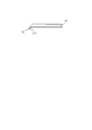
図1は、プレート式熱交換器10の正面図である。図2は、プレート式熱交換器10の側面図である。なお、図1では、内部構造を破線で示す。つまり、図1において破線で示した部分は、実際には正面から見えない構造である。
プレート式熱交換器10には、伝熱プレート1aと伝熱プレート1bとが交互に複数積層される。つまり、プレート式熱交換器10は、2つの異なる伝熱プレート1a,1bを備える。伝熱プレート1aと伝熱プレート1bとの間には、第1流体が流れる第1流路と、第2流体が流れる第2流路とが形成される。第1流路を流れる第1流体と、第2流路を流れる第2流体とは、混合されることなく、伝熱プレート1a,1bを介して熱交換される。
図1は、プレート式熱交換器10の正面図である。図2は、プレート式熱交換器10の側面図である。なお、図1では、内部構造を破線で示す。つまり、図1において破線で示した部分は、実際には正面から見えない構造である。
プレート式熱交換器10には、伝熱プレート1aと伝熱プレート1bとが交互に複数積層される。つまり、プレート式熱交換器10は、2つの異なる伝熱プレート1a,1bを備える。伝熱プレート1aと伝熱プレート1bとの間には、第1流体が流れる第1流路と、第2流体が流れる第2流路とが形成される。第1流路を流れる第1流体と、第2流路を流れる第2流体とは、混合されることなく、伝熱プレート1a,1bを介して熱交換される。
プレート式熱交換器10には、伝熱プレート1a,1bが積層された積層方向の一端側(図2のA側)に補強フレーム2aが積層される。また、プレート式熱交換器10には、伝熱プレート1a,1bが積層された積層方向の他端側(図2のB側)に補強フレーム2bが積層される。補強フレーム2aは、第1流体が流入する流入口4a(図3,6参照)とつながる配管継手3aと、第1流体が流出する流出口5a(図3,6参照)とつながる配管継手3bとを備える。また、補強フレーム2bは、第2流体が流入する流入口4b(図3,6参照)とつながる配管継手3cと、第2流体が流出する流出口5b(図3,6参照)とつながる配管継手3dとを備える。補強フレーム2a,2bは、プレート式熱交換器10の強度を保つために設けられる。
伝熱プレート1a,1b及び補強フレーム2a,2bは、ロウ付けにより永久的に結合される。これにより、伝熱プレート1aと伝熱プレート1bとの間に形成された第1流路と第2流路とを流れる第1流体と第2流体とは、それぞれの流路から外部へ漏れない構造となる。つまり、伝熱プレート1a,1bの外縁部6は、ロウ付けされ、密閉された状態になる。
なお、伝熱プレート1a,1bは、ステンレスやアルミ等により形成される。一方、ロウは、例えば、銅が用いられる。
伝熱プレート1a,1b及び補強フレーム2a,2bは、ロウ付けにより永久的に結合される。これにより、伝熱プレート1aと伝熱プレート1bとの間に形成された第1流路と第2流路とを流れる第1流体と第2流体とは、それぞれの流路から外部へ漏れない構造となる。つまり、伝熱プレート1a,1bの外縁部6は、ロウ付けされ、密閉された状態になる。
なお、伝熱プレート1a,1bは、ステンレスやアルミ等により形成される。一方、ロウは、例えば、銅が用いられる。
図3は、伝熱プレート1aの正面図である。図4は、伝熱プレート1aの側面図(図3のC方向から見た図)である。図5は、伝熱プレート1aの底面図(図3のD方向から見た図)である。図6は、伝熱プレート1bの正面図である。図7は、伝熱プレート1bの側面図(図6のE方向から見た図)である。図8は、伝熱プレート1bの底面図(図6のF方向から見た図)である。
図3から図5に示すように、伝熱プレート1aには、四隅(角)付近に、流入口4a、流出口5a、流入口4b、流出口5bが形成される。
また、伝熱プレート1aには、凹部と凸部(凹凸波形8)が長手方向に複数配列される。凹凸波形8は、短手方向の両端側に両端部を有し、両端部から長手方向にずれた位置に折り返し点を有する。これにより、凹凸波形8は、V字型に形成される。凹凸波形8は、伝熱プレート1aのほぼ全面に形成される。凹凸波形8は、第1流体と第2流体との熱交換を促進するために設けられる。
さらに、伝熱プレート1aには、外縁部6(外周部)の所定の位置に突出部7a(切り起こし)が形成される。突出部7aは、伝熱プレート1aの面と直交する方向に突出して形成される。つまり、突出部7aは、伝熱プレート1aが積層される方向に突出して形成される。突出部7aは、伝熱プレート1aの外縁部6の外側へ突出した突起を伝熱プレート1aの面と直交する方向へ折り曲げて形成される。ここでは、図2,4,5に示すように、突出部7aは、積層方向において補強フレーム2bが積層される側に折り曲げて形成される。
図3から図5に示すように、伝熱プレート1aには、四隅(角)付近に、流入口4a、流出口5a、流入口4b、流出口5bが形成される。
また、伝熱プレート1aには、凹部と凸部(凹凸波形8)が長手方向に複数配列される。凹凸波形8は、短手方向の両端側に両端部を有し、両端部から長手方向にずれた位置に折り返し点を有する。これにより、凹凸波形8は、V字型に形成される。凹凸波形8は、伝熱プレート1aのほぼ全面に形成される。凹凸波形8は、第1流体と第2流体との熱交換を促進するために設けられる。
さらに、伝熱プレート1aには、外縁部6(外周部)の所定の位置に突出部7a(切り起こし)が形成される。突出部7aは、伝熱プレート1aの面と直交する方向に突出して形成される。つまり、突出部7aは、伝熱プレート1aが積層される方向に突出して形成される。突出部7aは、伝熱プレート1aの外縁部6の外側へ突出した突起を伝熱プレート1aの面と直交する方向へ折り曲げて形成される。ここでは、図2,4,5に示すように、突出部7aは、積層方向において補強フレーム2bが積層される側に折り曲げて形成される。
伝熱プレート1bは、伝熱プレート1aと概ね同様の構成である。つまり、図6から図8に示すように、伝熱プレート1bには、四隅(角)付近に、流入口4a、流出口5a、流入口4b、流出口5bが形成される。
また、伝熱プレート1bには、凹凸波形8が長手方向に複数配列される。凹凸波形8は、短手方向の両端側に両端部を有し、両端部より長手方向にずれた位置に折り返し点を有する。これにより、凹凸波形8は、V字型に形成される。
さらに、伝熱プレート1bには、外縁部6の所定の位置に突出部7b(切り起こし)が形成される。ここでは、突出部7bは、伝熱プレート1bの長手方向の外縁部6の所定の位置に形成される。突出部7bは、伝熱プレート1bの面と直交する方向に突出して形成される。突出部7bは、伝熱プレート1bの外縁部6の外側へ突出した突起を伝熱プレート1bの面と直交する方向へ折り曲げて形成される。ここでは、図2,7,8に示すように、突出部7bは、積層方向において補強フレーム2bが積層される側に折り曲げて形成される。
なお、突出部7bは、伝熱プレート1a,1bが正しく積層された場合に、突出部7aが形成された外縁部6と同一側面となる外縁部6に形成される。図では、流入孔4bと流出孔5bとが形成された側の長辺に突出部7a,7bが形成されている。そのため、図2に示すように、伝熱プレート1a,1bが正しく積層されたプレート式熱交換器10の所定の側面には、全ての伝熱プレート1a,1bに形成された突出部7a,7bが配置される。
また、伝熱プレート1bには、凹凸波形8が長手方向に複数配列される。凹凸波形8は、短手方向の両端側に両端部を有し、両端部より長手方向にずれた位置に折り返し点を有する。これにより、凹凸波形8は、V字型に形成される。
さらに、伝熱プレート1bには、外縁部6の所定の位置に突出部7b(切り起こし)が形成される。ここでは、突出部7bは、伝熱プレート1bの長手方向の外縁部6の所定の位置に形成される。突出部7bは、伝熱プレート1bの面と直交する方向に突出して形成される。突出部7bは、伝熱プレート1bの外縁部6の外側へ突出した突起を伝熱プレート1bの面と直交する方向へ折り曲げて形成される。ここでは、図2,7,8に示すように、突出部7bは、積層方向において補強フレーム2bが積層される側に折り曲げて形成される。
なお、突出部7bは、伝熱プレート1a,1bが正しく積層された場合に、突出部7aが形成された外縁部6と同一側面となる外縁部6に形成される。図では、流入孔4bと流出孔5bとが形成された側の長辺に突出部7a,7bが形成されている。そのため、図2に示すように、伝熱プレート1a,1bが正しく積層されたプレート式熱交換器10の所定の側面には、全ての伝熱プレート1a,1bに形成された突出部7a,7bが配置される。
伝熱プレート1aに形成された凹凸波形8と、伝熱プレート1bに形成された凹凸波形8とは、V字型の向きが逆である。つまり、伝熱プレート1aでは、両端部より長手方向下側に折り返し点を有するV字型に凹凸波形8が形成されるのに対し、伝熱プレート1bでは、両端部より長手方向上側に折り返し点を有するV字型(逆V字型)に凹凸波形8が形成される。
そのため、伝熱プレート1a,1bを積層すると、図1に示すように、逆向きに形成された凹凸波形8が交差した構造となる。これにより伝熱効率のよい流路が形成される。
そのため、伝熱プレート1a,1bを積層すると、図1に示すように、逆向きに形成された凹凸波形8が交差した構造となる。これにより伝熱効率のよい流路が形成される。
また、伝熱プレート1aの長手方向端部から突出部7aまでの長さL1(図4)と、伝熱プレート1bの長手方向端部から突出部7bまでの長さL2(図7)とは、長さが異なる。そのため、図1,2に示すように、伝熱プレート1a,1bが積層された場合に、突出部7aと突出部7bとは、伝熱プレート1a,1bの長手方向(図2のC方向)にずれた位置となる。
ここでは、長さL1と長さL2との差(L1-L2の絶対値)は、突出部7aの長手方向の長さL3(図3)と突出部7bの長手方向の長さL4(図6)とのどちらよりも長い。そのため、図1,2に示すように、伝熱プレート1a,1bが積層された場合に、突出部7aと突出部7bとの間には、長手方向(図2のC方向)に隙間が空く。
ここでは、長さL1と長さL2との差(L1-L2の絶対値)は、突出部7aの長手方向の長さL3(図3)と突出部7bの長手方向の長さL4(図6)とのどちらよりも長い。そのため、図1,2に示すように、伝熱プレート1a,1bが積層された場合に、突出部7aと突出部7bとの間には、長手方向(図2のC方向)に隙間が空く。
また、突出部7aの積層方向の長さL5(図4)と、突出部7bの積層方向の長さL6(図7)とは、伝熱プレート1a,1bが積層された場合の伝熱プレート1a,1b間の幅W1,W2(図2)の和(W1+W2)よりも短い。ここでは、W1とW2とは略同一であるから、L5とL6とは、2倍のW1(又は2倍のW2)よりも短い。そのため、図2に示すように、伝熱プレート1a,1bが交互に積層された場合に、突出部7aや突出部7bが他のプレートの突出部7aや突出部7bと当たることはない。
また、L5とL6とを幅W1,W2よりも短くしてもよい。この場合、誤って同一の伝熱プレート1aが連続して積層された場合であっても、2つの突出部7aが面方向に重なることはない。
また、L5とL6とを幅W1,W2よりも短くしてもよい。この場合、誤って同一の伝熱プレート1aが連続して積層された場合であっても、2つの突出部7aが面方向に重なることはない。
また、上述したように、突出部7a,7bは、外縁部6の外側へ突出した突起を伝熱プレート1a,1bの面と直交する方向へ折り曲げて形成される。ここでは、突起を折り曲げる角度θ1,θ2(図5,8)は、略90度としている。しかし、突起を折り曲げる角度θ1,θ2(図5,8)は、90度よりも大きくても小さくてもよい。
(2)プレート式熱交換器10における伝熱プレート1a,1bの積層配列が正しいか否かを判定する積層判定装置20について説明する。
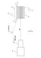
図9は、プレート式熱交換器10における伝熱プレート1a,1bの積層配列が正しいか否か判定する処理の説明図である。
図9に示すように、プレート式熱交換器10の外縁部6を積層判定装置20が備える撮影装置により撮影する。撮影装置とは、例えば、カメラ916である。また、積層判定装置20は、プレート式熱交換器10の外縁部6のうち、突出部7a,7bが形成された面を正面から撮影する。つまり、積層判定装置20は、プレート式熱交換器10の突出部7a,7bが形成された面をプレートの面方向から撮影する。積層判定装置20は、撮影して取得した画像情報と予め記憶した画像情報とを比較して、プレート式熱交換器10における伝熱プレート1a,1bの積層配列が正しいか否かを判定する。
図9は、プレート式熱交換器10における伝熱プレート1a,1bの積層配列が正しいか否か判定する処理の説明図である。
図9に示すように、プレート式熱交換器10の外縁部6を積層判定装置20が備える撮影装置により撮影する。撮影装置とは、例えば、カメラ916である。また、積層判定装置20は、プレート式熱交換器10の外縁部6のうち、突出部7a,7bが形成された面を正面から撮影する。つまり、積層判定装置20は、プレート式熱交換器10の突出部7a,7bが形成された面をプレートの面方向から撮影する。積層判定装置20は、撮影して取得した画像情報と予め記憶した画像情報とを比較して、プレート式熱交換器10における伝熱プレート1a,1bの積層配列が正しいか否かを判定する。
図10は、積層判定装置20の機能を示す機能ブロック図である。
積層判定装置20は、画像情報取得部21、画像情報記憶部22、積層判定部23を備える。
画像情報取得部21は、撮影装置により、プレート式熱交換器10の外縁部6の画像情報を取得する(画像情報取得ステップ)。特に、画像情報取得部21は、突出部7a,7bが形成された部分全体の画像情報を取得する。つまり、画像情報取得部21は、突出部7a,7bにより形成された模様の画像情報を取得する。
画像情報記憶部22は、所定の模様の画像情報を予め記憶装置に記憶する。例えば、画像情報記憶部22は、図2に示すような正しく積層された場合に、突出部7a,7bにより形成される模様の画像情報を記憶する。
積層判定部23は、画像情報取得部21が取得した画像情報(撮影画像)と、画像情報記憶部22が記憶した画像情報(記憶画像)とを処理装置により比較する。そして、積層判定部23は、撮影画像が示すプレート式熱交換器10の伝熱プレート1a,1bの積層配列が正しいか否かを処理装置により判定する(積層判定ステップ)。例えば、積層判定部23は、撮影画像と記憶画像とを比較して、撮影画像と記憶画像との一致の程度を定量化し評価する。積層判定部23は、撮影画像と記憶画像との一致の程度が高ければ、撮影画像が示すプレート式熱交換器10の伝熱プレート1a,1bの積層配列が正しいと判定する。一方、積層判定部23は、撮影画像と記憶画像との一致の程度が低ければ、撮影画像が示すプレート式熱交換器10の伝熱プレート1a,1bの積層配列が正しくないと判定する。例えば、積層判定部23は、突出部7a,7bの相対的な位置、突出部7a,7bの数を定量化して判定する。
積層判定装置20は、画像情報取得部21、画像情報記憶部22、積層判定部23を備える。
画像情報取得部21は、撮影装置により、プレート式熱交換器10の外縁部6の画像情報を取得する(画像情報取得ステップ)。特に、画像情報取得部21は、突出部7a,7bが形成された部分全体の画像情報を取得する。つまり、画像情報取得部21は、突出部7a,7bにより形成された模様の画像情報を取得する。
画像情報記憶部22は、所定の模様の画像情報を予め記憶装置に記憶する。例えば、画像情報記憶部22は、図2に示すような正しく積層された場合に、突出部7a,7bにより形成される模様の画像情報を記憶する。
積層判定部23は、画像情報取得部21が取得した画像情報(撮影画像)と、画像情報記憶部22が記憶した画像情報(記憶画像)とを処理装置により比較する。そして、積層判定部23は、撮影画像が示すプレート式熱交換器10の伝熱プレート1a,1bの積層配列が正しいか否かを処理装置により判定する(積層判定ステップ)。例えば、積層判定部23は、撮影画像と記憶画像とを比較して、撮影画像と記憶画像との一致の程度を定量化し評価する。積層判定部23は、撮影画像と記憶画像との一致の程度が高ければ、撮影画像が示すプレート式熱交換器10の伝熱プレート1a,1bの積層配列が正しいと判定する。一方、積層判定部23は、撮影画像と記憶画像との一致の程度が低ければ、撮影画像が示すプレート式熱交換器10の伝熱プレート1a,1bの積層配列が正しくないと判定する。例えば、積層判定部23は、突出部7a,7bの相対的な位置、突出部7a,7bの数を定量化して判定する。
上述したように、プレート式熱交換器10の伝熱プレート1a,1bは、ロウ付けされる。特に、伝熱プレート1a,1bの外縁部6もロウ付けされる。一方、突出部7a,7bはロウ付けされない。ロウ付けには、伝熱プレート1a,1bとは異なる金属を用いる。したがって、ロウ付けされた部分は、ロウ付けされていない部分とは色や光沢が異なる。
つまり、突出部7a,7bと、伝熱プレート1a,1bの外縁部6とは、異なる色や光沢となる。特に、通常ロウ付けされた部分は、光沢が無くなる。
そのため、撮影画像において、突出部7a,7bと、突出部7a,7b以外の部分(伝熱プレート1a,1bの外縁部6)とは、明確に区別され、容易に識別可能な状態となる。つまり、撮影画像において、突出部7a,7bは光沢があるため明るい色(白色)となるのに対し、突出部7a,7b以外の部分は光沢がないため暗い色(黒色)となる。
つまり、突出部7a,7bと、伝熱プレート1a,1bの外縁部6とは、異なる色や光沢となる。特に、通常ロウ付けされた部分は、光沢が無くなる。
そのため、撮影画像において、突出部7a,7bと、突出部7a,7b以外の部分(伝熱プレート1a,1bの外縁部6)とは、明確に区別され、容易に識別可能な状態となる。つまり、撮影画像において、突出部7a,7bは光沢があるため明るい色(白色)となるのに対し、突出部7a,7b以外の部分は光沢がないため暗い色(黒色)となる。
図11は、撮影画像の取得方法を示す図である。
図11に示す撮影画像の取得方法においては、照明器具30により、プレート式熱交換器10の突出部7a,7bが形成された面へ光を当てた状態で、積層判定装置20は撮影画像を取得する。
特に、照明器具30は、プレート式熱交換器10の突出部7a,7bが形成された面の正面よりも、伝熱プレート1a,1bの積層方向(図11のG方向)へずれた位置から光を当てる。
また、この場合、突起を折り曲げる角度θ1,θ2(図5,8)を90度からずらして、突出部7a,7bの面が照明器具30の方向を向く角度にする。つまり、図11であれば、突起を折り曲げる角度θ1,θ2(図5,8)を90度よりも大きくする。
これにより、光沢のある突出部7a,7bと、光沢のない突出部7a,7b以外の部分との撮影画像における差異がより明確になる。つまり、突出部7a,7bは、照明器具30により当てられた光を反射するため、明るい色(白色)となる。特に、突出部7a,7bの面は、照明器具30側を向いているため、照明器具30から当てられた光を反射し易い。一方、突出部7a,7b以外の部分は、光沢がなく照明器具30から当てられた光をほとんど反射しない。そのため、突出部7a,7bと、突出部7a,7b以外の部分とを判別し易い。
図11に示す撮影画像の取得方法においては、照明器具30により、プレート式熱交換器10の突出部7a,7bが形成された面へ光を当てた状態で、積層判定装置20は撮影画像を取得する。
特に、照明器具30は、プレート式熱交換器10の突出部7a,7bが形成された面の正面よりも、伝熱プレート1a,1bの積層方向(図11のG方向)へずれた位置から光を当てる。
また、この場合、突起を折り曲げる角度θ1,θ2(図5,8)を90度からずらして、突出部7a,7bの面が照明器具30の方向を向く角度にする。つまり、図11であれば、突起を折り曲げる角度θ1,θ2(図5,8)を90度よりも大きくする。
これにより、光沢のある突出部7a,7bと、光沢のない突出部7a,7b以外の部分との撮影画像における差異がより明確になる。つまり、突出部7a,7bは、照明器具30により当てられた光を反射するため、明るい色(白色)となる。特に、突出部7a,7bの面は、照明器具30側を向いているため、照明器具30から当てられた光を反射し易い。一方、突出部7a,7b以外の部分は、光沢がなく照明器具30から当てられた光をほとんど反射しない。そのため、突出部7a,7bと、突出部7a,7b以外の部分とを判別し易い。
積層判定装置20により、伝熱プレート1a,1bの積層配列が正しいと判定される例を説明する。
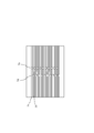
図12は、伝熱プレート1a,1bが正しく積層されたプレート式熱交換器10を撮影した撮影画像を示す図である。
図12に示すように、伝熱プレート1a,1bが正しく積層されたプレート式熱交換器10の撮影画像には、積層方向に突出部7a,7bが交互に現れる。上述したように、距離L1と距離L2とが異なるため、伝熱プレート1a,1bが積層された場合に、突出部7aと突出部7bとは、伝熱プレート1a,1bの長手方向にずれた位置となる。したがって、積層判定部23は、撮影画像と記憶画像とにおける突出部7aと突出部7bとの相対的な位置関係を比較することにより、図12に示すプレート式熱交換器10の伝熱プレート1a,1bの積層配列が正しいと判定できる。
図12は、伝熱プレート1a,1bが正しく積層されたプレート式熱交換器10を撮影した撮影画像を示す図である。
図12に示すように、伝熱プレート1a,1bが正しく積層されたプレート式熱交換器10の撮影画像には、積層方向に突出部7a,7bが交互に現れる。上述したように、距離L1と距離L2とが異なるため、伝熱プレート1a,1bが積層された場合に、突出部7aと突出部7bとは、伝熱プレート1a,1bの長手方向にずれた位置となる。したがって、積層判定部23は、撮影画像と記憶画像とにおける突出部7aと突出部7bとの相対的な位置関係を比較することにより、図12に示すプレート式熱交換器10の伝熱プレート1a,1bの積層配列が正しいと判定できる。
積層判定装置20により、伝熱プレート1a,1bの積層配列が正しくないと判定される例を説明する。
図13は、伝熱プレート1a,1bの積層順序が入れ替わって積層されたプレート式熱交換器10を撮影した撮影画像を示す図である。なお、図13では、積層順序が入れ替わった部分を破線で囲って示す。
図13に示すように、伝熱プレート1a,1bの積層順序が入れ替わって積層されたプレート式熱交換器10の撮影画像には、積層方向に突出部7a,7bが交互に現れない箇所がある。したがって、積層判定部23は、撮影画像と記憶画像とにおける突出部7aと突出部7bとの相対的な位置関係を比較することにより、図13に示すプレート式熱交換器10の伝熱プレート1a,1bの積層配列が正しくないと判定できる。
また、積層順序が入れ替わった箇所では、突出部7aと突出部7bとがそれぞれ2つ連続して現れている。つまり、積層判定部23は、突出部7aと突出部7bとが連続して現れた場合には、積層順序が入れ替わったと判定することができる。すなわち、積層判定部23は、伝熱プレート1a,1bの積層配列が正しくないと判定した場合に、さらに撮影画像において突出部7aと突出部7bとが連続して現れる箇所があるか否かを判定する。これにより、伝熱プレート1a,1bの積層配列が正しくない原因が伝熱プレート1a,1bの積層順序が入れ替わったことであるか否かを判定することができる。
図13は、伝熱プレート1a,1bの積層順序が入れ替わって積層されたプレート式熱交換器10を撮影した撮影画像を示す図である。なお、図13では、積層順序が入れ替わった部分を破線で囲って示す。
図13に示すように、伝熱プレート1a,1bの積層順序が入れ替わって積層されたプレート式熱交換器10の撮影画像には、積層方向に突出部7a,7bが交互に現れない箇所がある。したがって、積層判定部23は、撮影画像と記憶画像とにおける突出部7aと突出部7bとの相対的な位置関係を比較することにより、図13に示すプレート式熱交換器10の伝熱プレート1a,1bの積層配列が正しくないと判定できる。
また、積層順序が入れ替わった箇所では、突出部7aと突出部7bとがそれぞれ2つ連続して現れている。つまり、積層判定部23は、突出部7aと突出部7bとが連続して現れた場合には、積層順序が入れ替わったと判定することができる。すなわち、積層判定部23は、伝熱プレート1a,1bの積層配列が正しくないと判定した場合に、さらに撮影画像において突出部7aと突出部7bとが連続して現れる箇所があるか否かを判定する。これにより、伝熱プレート1a,1bの積層配列が正しくない原因が伝熱プレート1a,1bの積層順序が入れ替わったことであるか否かを判定することができる。
図14は、伝熱プレート1a,1b(ここでは、伝熱プレート1b)が反転して積層されたプレート式熱交換器10を撮影した撮影画像を示す図である。なお、図14では、伝熱プレート1bが反転した部分を破線で囲って示す。また、伝熱プレート1a,1bが反転した場合とは、伝熱プレート1bが上下逆さまに積層された場合や、伝熱プレート1a,1bが左右逆さまに積層された場合である。
図14に示すように、伝熱プレート1a,1bが反転して積層されたプレート式熱交換器10の撮影画像には、突出部7a又は突出部7bが現れない箇所がある。上述したように、伝熱プレート1a,1bが正しく積層された場合に、突出部7a,7bはプレート式熱交換器10の同一側面となる外縁部6に形成されている。そのため、反転して積層された伝熱プレート1a,1bの突出部7a,7bは、撮影した側面の裏側の側面になってしまう。したがって、積層判定部23は、撮影画像と記憶画像とにおける突出部7aと突出部7bとの相対的な位置関係を比較することにより、図14に示すプレート式熱交換器10の伝熱プレート1a,1bの積層配列が正しくないと判定できる。
また、積層判定部23は、突出部7a又は突出部7bが現れない箇所がある場合には、積層順序が入れ替わったと判定することができる。すなわち、積層判定部23は、伝熱プレート1a,1bの積層配列が正しくないと判定した場合に、さらに撮影画像において突出部7a又は突出部7bが現れない箇所があるか否かを判定する。これにより、伝熱プレート1a,1bの積層配列が正しくない原因が伝熱プレート1a,1bが反転したことであるか否かを判定することができる。
図14に示すように、伝熱プレート1a,1bが反転して積層されたプレート式熱交換器10の撮影画像には、突出部7a又は突出部7bが現れない箇所がある。上述したように、伝熱プレート1a,1bが正しく積層された場合に、突出部7a,7bはプレート式熱交換器10の同一側面となる外縁部6に形成されている。そのため、反転して積層された伝熱プレート1a,1bの突出部7a,7bは、撮影した側面の裏側の側面になってしまう。したがって、積層判定部23は、撮影画像と記憶画像とにおける突出部7aと突出部7bとの相対的な位置関係を比較することにより、図14に示すプレート式熱交換器10の伝熱プレート1a,1bの積層配列が正しくないと判定できる。
また、積層判定部23は、突出部7a又は突出部7bが現れない箇所がある場合には、積層順序が入れ替わったと判定することができる。すなわち、積層判定部23は、伝熱プレート1a,1bの積層配列が正しくないと判定した場合に、さらに撮影画像において突出部7a又は突出部7bが現れない箇所があるか否かを判定する。これにより、伝熱プレート1a,1bの積層配列が正しくない原因が伝熱プレート1a,1bが反転したことであるか否かを判定することができる。
図15は、伝熱プレート1a,1b(ここでは、伝熱プレート1b)の積層枚数が少ないプレート式熱交換器10を撮影した撮影画像を示す図である。なお、図15では、積層枚数が1枚足りない。つまり、図9に示すように、正しく積層されたプレート式熱交換器10は、伝熱プレート1aが10枚と伝熱プレート1bが10枚との合計20枚の伝熱プレート1a,1bが積層されている。しかし、図15では、伝熱プレート1aが10枚と伝熱プレート1bが9との合計19枚の伝熱プレート1a,1bしか積層されていない。
図15に示すように、積層枚数が異なって積層されたプレート式熱交換器10の撮影画像では、突出部7a又は突出部7bの数が少ない。したがって、積層判定部23は、撮影画像と記憶画像とにおける突出部7aと突出部7bとの数を比較することにより、図15に示すプレート式熱交換器10の伝熱プレート1a,1bの積層配列が正しくないと判定できる。
また、積層判定部23は、突出部7a又は突出部7bの数により、積層枚数が何枚少ないということを判定できる。すなわち、積層判定部23は、伝熱プレート1a,1bの積層配列が正しくないと判定した場合に、さらに撮影画像において突出部7a又は突出部7bの数が足りるか否かを判定する。これにより、伝熱プレート1a,1bの積層配列が正しくない原因が伝熱プレート1a,1bの積層枚数が少ないことであるか否かを判定することができる。
なお、伝熱プレート1a,1bの積層枚数が多い場合も同様に、突出部7a又は突出部7bの数により判定できる。
図15に示すように、積層枚数が異なって積層されたプレート式熱交換器10の撮影画像では、突出部7a又は突出部7bの数が少ない。したがって、積層判定部23は、撮影画像と記憶画像とにおける突出部7aと突出部7bとの数を比較することにより、図15に示すプレート式熱交換器10の伝熱プレート1a,1bの積層配列が正しくないと判定できる。
また、積層判定部23は、突出部7a又は突出部7bの数により、積層枚数が何枚少ないということを判定できる。すなわち、積層判定部23は、伝熱プレート1a,1bの積層配列が正しくないと判定した場合に、さらに撮影画像において突出部7a又は突出部7bの数が足りるか否かを判定する。これにより、伝熱プレート1a,1bの積層配列が正しくない原因が伝熱プレート1a,1bの積層枚数が少ないことであるか否かを判定することができる。
なお、伝熱プレート1a,1bの積層枚数が多い場合も同様に、突出部7a又は突出部7bの数により判定できる。
以上の説明では、伝熱プレートは、伝熱プレート1a,1bのみであるものとして説明した。しかし、伝熱プレート1a,1b以外の伝熱プレートがあり、伝熱プレート1a,1b以外の伝熱プレートが積層されてしまう虞もある。この場合であっても、伝熱プレートの種類に応じて異なる位置に突出部を形成することにより、積層配列が正しいか否かを判定することができる。
図16は、異なる種類の伝熱プレート(ここでは、伝熱プレート1c)が混在して積層されたプレート式熱交換器10を撮影した撮影画像を示す図である。なお、図16では、異なる伝熱プレートが積層された部分を破線で囲って示す。
図16に示すように、伝熱プレート1cが混在して積層されたプレート式熱交換器10の撮影画像には、突出部7aと突出部7bとが形成された位置とは異なる位置に突出部7cが形成される。したがって、積層判定部23は、撮影画像と記憶画像とにおける突出部7aと突出部7bとの相対的な位置関係を比較することにより、図16に示すプレート式熱交換器10の伝熱プレート1a,1bの積層配列が正しくないと判定できる。
また、積層判定部23は、突出部7cの位置により、異なる種類の伝熱プレートが混在して積層されたということを判定できる。すなわち、積層判定部23は、伝熱プレート1a,1bの積層配列が正しくないと判定した場合に、さらに撮影画像において突出部7aと突出部7bとの位置と異なる位置に突出部が形成されているかを判定する。これにより、伝熱プレート1a,1bの積層配列が正しくない原因が異なる種類の伝熱プレートが積層されたことかである否かを判定することができる。また、積層判定部23は、異なる種類の伝熱プレートが積層されたと判定した場合に、その伝熱プレートに形成された突出部の位置から、どの伝熱プレートが混在して積層されたということも判定できる。
図16は、異なる種類の伝熱プレート(ここでは、伝熱プレート1c)が混在して積層されたプレート式熱交換器10を撮影した撮影画像を示す図である。なお、図16では、異なる伝熱プレートが積層された部分を破線で囲って示す。
図16に示すように、伝熱プレート1cが混在して積層されたプレート式熱交換器10の撮影画像には、突出部7aと突出部7bとが形成された位置とは異なる位置に突出部7cが形成される。したがって、積層判定部23は、撮影画像と記憶画像とにおける突出部7aと突出部7bとの相対的な位置関係を比較することにより、図16に示すプレート式熱交換器10の伝熱プレート1a,1bの積層配列が正しくないと判定できる。
また、積層判定部23は、突出部7cの位置により、異なる種類の伝熱プレートが混在して積層されたということを判定できる。すなわち、積層判定部23は、伝熱プレート1a,1bの積層配列が正しくないと判定した場合に、さらに撮影画像において突出部7aと突出部7bとの位置と異なる位置に突出部が形成されているかを判定する。これにより、伝熱プレート1a,1bの積層配列が正しくない原因が異なる種類の伝熱プレートが積層されたことかである否かを判定することができる。また、積層判定部23は、異なる種類の伝熱プレートが積層されたと判定した場合に、その伝熱プレートに形成された突出部の位置から、どの伝熱プレートが混在して積層されたということも判定できる。
また、以上の説明では、伝熱プレート1a,1bが交互に積層された場合に、積層配列が正しいとした。しかし、複数の種類のプレート式熱交換器を製造する場合においては、異なる積層配列も正しい積層配列である場合がある。例えば、伝熱プレート1a,1bが交互に積層されたプレート式熱交換器10以外に、伝熱プレート1c,1dが交互に積層されたプレート式熱交換器11(図示せず)を製造している場合もある。この場合、伝熱プレート1c,1dが交互に積層されていても、正しい積層配列である。このような場合にも、伝熱プレートの種類に応じて異なる位置に突出部を形成することにより、積層配列が正しいか否かを判定することができる。
図17は、伝熱プレート1c,1dが正しく積層されたプレート式熱交換器11を撮影した撮影画像を示す図である。なお、伝熱プレート1a,1bが交互に積層された場合はプレート式熱交換器10の正しい積層配列であり、伝熱プレート1c,1dが交互に積層された場合はプレート式熱交換器11の正しい積層配列であるとする。
図17に示すように、伝熱プレート1c,1dが交互に積層されたプレート式熱交換器11の撮影画像には、突出部7aと突出部7bとが形成される位置とは異なる位置に突出部7cと突出部7dとが形成される。したがって、積層判定部23は、撮影画像における突出部7cと突出部7dと記憶画像における突出部7aと突出部7bとの相対的な位置関係を比較することにより、図17に示すプレート式熱交換器11は、正しい積層配列のプレート式熱交換器10ではないと判定できる。
また、伝熱プレート1c,1dが交互に積層されたプレート式熱交換器11についても、突出部7c,7dにより形成される模様の画像情報を画像情報記憶部22が予め記憶しておく。そして、積層判定部23は、正しい積層配列のプレート式熱交換器10ではないと判定した場合に、突出部7c,7dにより形成される模様の画像情報と撮影画像とを比較する。これにより、積層判定部23は、図17に示すプレート式熱交換器11が、プレート式熱交換器10とは異なるが、正しい積層配列のプレート式熱交換器11であると判定できる。つまり、積層判定部23は、画像情報記憶部22が記憶した画像情報が複数ある場合には、どの記憶画像が示す模様と一致したかにより、どのプレート式熱交換器10の積層配列と一致したかを判定することができる。
図17は、伝熱プレート1c,1dが正しく積層されたプレート式熱交換器11を撮影した撮影画像を示す図である。なお、伝熱プレート1a,1bが交互に積層された場合はプレート式熱交換器10の正しい積層配列であり、伝熱プレート1c,1dが交互に積層された場合はプレート式熱交換器11の正しい積層配列であるとする。
図17に示すように、伝熱プレート1c,1dが交互に積層されたプレート式熱交換器11の撮影画像には、突出部7aと突出部7bとが形成される位置とは異なる位置に突出部7cと突出部7dとが形成される。したがって、積層判定部23は、撮影画像における突出部7cと突出部7dと記憶画像における突出部7aと突出部7bとの相対的な位置関係を比較することにより、図17に示すプレート式熱交換器11は、正しい積層配列のプレート式熱交換器10ではないと判定できる。
また、伝熱プレート1c,1dが交互に積層されたプレート式熱交換器11についても、突出部7c,7dにより形成される模様の画像情報を画像情報記憶部22が予め記憶しておく。そして、積層判定部23は、正しい積層配列のプレート式熱交換器10ではないと判定した場合に、突出部7c,7dにより形成される模様の画像情報と撮影画像とを比較する。これにより、積層判定部23は、図17に示すプレート式熱交換器11が、プレート式熱交換器10とは異なるが、正しい積層配列のプレート式熱交換器11であると判定できる。つまり、積層判定部23は、画像情報記憶部22が記憶した画像情報が複数ある場合には、どの記憶画像が示す模様と一致したかにより、どのプレート式熱交換器10の積層配列と一致したかを判定することができる。
以上のように、プレート式熱交換器の各伝熱プレートには、伝熱プレートの種類に応じて異なる位置に突出部が設けられている。そのため、積層判定装置20は、伝熱プレートの積層配列が正しいか否かを判定することができる。つまり、センサ916やカメラを用いて精度よく積層配列が正しいか否かを判定することができる。
したがって、積層配列が正しくないままロウ付けしてしまいことを防止できる。また、積層配列が正しくないプレート式熱交換器を製造してしまい、プレート式熱交換器10を廃却することや、積層配列が正しくないプレート式熱交換器を市場へ流出してしまう可能性を排除できる。つまり、信頼性の高い製品を人件費を掛けず安価に製造することができる。
また、積層判定装置20は、撮影画像における突出部の配列から、積層配列が正しくない理由を判定することもできる。そのため、積層配列の修正作業も簡略化でき、効率よく積層配列の修正が可能となり、作業能率が向上する。
したがって、積層配列が正しくないままロウ付けしてしまいことを防止できる。また、積層配列が正しくないプレート式熱交換器を製造してしまい、プレート式熱交換器10を廃却することや、積層配列が正しくないプレート式熱交換器を市場へ流出してしまう可能性を排除できる。つまり、信頼性の高い製品を人件費を掛けず安価に製造することができる。
また、積層判定装置20は、撮影画像における突出部の配列から、積層配列が正しくない理由を判定することもできる。そのため、積層配列の修正作業も簡略化でき、効率よく積層配列の修正が可能となり、作業能率が向上する。
なお、伝熱プレートは、例えば、プレス加工により製造される。突出部は、上述したように、外縁部の外側へ突出した突起を伝熱プレートの面と直交する方向へ折り曲げて形成される。したがって、伝熱プレートを製造する際、外縁部の外側へ突出した突起も形成しておき、折り曲げることにより突出部を形成することができる。
つまり、突出部を備える伝熱プレートは、プレス加工による抜き加工、曲げ加工により製造することができる。
また、突出部のない伝熱プレートを製造する場合に、最終的に伝熱プレートの外縁部の外側にある切り落とし部分に、突出部を形成する。そのため、突出部を形成した場合であっても、材料費が増加することもない。
つまり、突出部を備える伝熱プレートは、プレス加工による抜き加工、曲げ加工により製造することができる。
また、突出部のない伝熱プレートを製造する場合に、最終的に伝熱プレートの外縁部の外側にある切り落とし部分に、突出部を形成する。そのため、突出部を形成した場合であっても、材料費が増加することもない。
また、上記説明では、各伝熱プレートには、伝熱プレートの種類に応じて異なる位置に突出部が形成されるとした。しかし、各伝熱プレートには、伝熱プレートの種類に応じて異なる形状の突出部が形成されるとしてもよい。また、各伝熱プレートには、伝熱プレートの種類に応じて異なる位置に、異なる形状の突出部が形成されるとしてもよい。
また、上記説明では、各伝熱プレートには、1つの突出部が形成される例を説明した。しかし、各伝熱プレートに、突出部を複数形成してもよい。
図18は、各伝熱プレートに、2つの突出部を形成した例を示す図である。
図18では、伝熱プレート1eに突出部7e,7gを形成し、伝熱プレート1fに突出部7f,7hを形成した。突出部7eは、突出部7f,7g,7hと異なる位置に形成される。また、突出部7fは、突出部7e,7g,7hと異なる位置に形成される。一方、突出部7gと突出部7hとは、同一の位置に形成される。例えば、突出部7gと突出部7hとは、伝熱プレート1e,1fの長手方向の中点に形成される。
突出部7gと突出部7hとを同一の位置に形成するとともに、突出部7eと突出部7fとを異なる位置に形成したことにより、突出部7gと突出部7eとの間の距離と、突出部7hと突出部7fとの間の距離とは異なる。
そのため、伝熱プレート1e,1fにおいて、2つの突出部の間の距離を測ることにより、伝熱プレートの種類を判定することができる。
図18は、各伝熱プレートに、2つの突出部を形成した例を示す図である。
図18では、伝熱プレート1eに突出部7e,7gを形成し、伝熱プレート1fに突出部7f,7hを形成した。突出部7eは、突出部7f,7g,7hと異なる位置に形成される。また、突出部7fは、突出部7e,7g,7hと異なる位置に形成される。一方、突出部7gと突出部7hとは、同一の位置に形成される。例えば、突出部7gと突出部7hとは、伝熱プレート1e,1fの長手方向の中点に形成される。
突出部7gと突出部7hとを同一の位置に形成するとともに、突出部7eと突出部7fとを異なる位置に形成したことにより、突出部7gと突出部7eとの間の距離と、突出部7hと突出部7fとの間の距離とは異なる。
そのため、伝熱プレート1e,1fにおいて、2つの突出部の間の距離を測ることにより、伝熱プレートの種類を判定することができる。
また、上記説明では、突出部は、各伝熱プレートの長辺側の外縁部6に形成されるとした。しかし、突出部は、各伝熱プレートの短辺側の外縁部6に形成されてもよい。
また、積層判定装置20は、撮影装置により撮影することに代え、レーザ光を当てて、反射光を読み取ることにより突出部の位置や数を認識してもよい。
以上をまとめると、実施の形態1に係るプレート式熱交換器は、複数種類の伝熱プレートを積層し、その積層されたそれぞれの伝熱プレートには、伝熱を促進するための、波形状がほぼ全面に備えられ、かつ、伝熱プレートの4角付近には熱交換を行う冷媒体と熱媒体それぞれの流入口と流出口が備えられ、それぞれの流入口から導入された冷媒体、熱媒体は混合されることなく、伝熱プレートの表裏面のそれぞれを流れることで熱交換を行い、流出口へと排出される構造となっているが、その伝熱プレートを積層後、ロウ付けによって永久的に接合してなるプレート式熱交換器において、ロウ付け前に伝熱プレートの積層状態を判別するために、伝熱プレートの外縁部に突起を備え、かつ、その突起がおおよそ積層方向に折り曲げられていることで、その伝熱プレートの積層状態を判別しようと、その折り曲げられた突起の配列を見たときに、折り曲げられた突起の面が、付近の他の部分と明らかに異なる見え方となり、画像処理を用いて積層状態を判別できる特徴を備えるものである。
次に、積層判定装置20のハードウェア構成について説明する。
図19は、積層判定装置20のハードウェア構成の一例を示す図である。
図19に示すように、積層判定装置20は、プログラムを実行するCPU911(Central・Processing・Unit、中央処理装置、処理装置、演算装置、マイクロプロセッサ、マイクロコンピュータ、プロセッサともいう)を備えている。CPU911は、バス912を介してROM913、RAM914、LCD901(Liquid Crystal Display)、キーボード902(K/B)、通信ボード915、カメラ916、磁気ディスク装置920と接続され、これらのハードウェアデバイスを制御する。磁気ディスク装置920(固定ディスク装置)の代わりに、光ディスク装置、メモリカード読み書き装置などの記憶装置でもよい。磁気ディスク装置920は、所定の固定ディスクインタフェースを介して接続される。
図19は、積層判定装置20のハードウェア構成の一例を示す図である。
図19に示すように、積層判定装置20は、プログラムを実行するCPU911(Central・Processing・Unit、中央処理装置、処理装置、演算装置、マイクロプロセッサ、マイクロコンピュータ、プロセッサともいう)を備えている。CPU911は、バス912を介してROM913、RAM914、LCD901(Liquid Crystal Display)、キーボード902(K/B)、通信ボード915、カメラ916、磁気ディスク装置920と接続され、これらのハードウェアデバイスを制御する。磁気ディスク装置920(固定ディスク装置)の代わりに、光ディスク装置、メモリカード読み書き装置などの記憶装置でもよい。磁気ディスク装置920は、所定の固定ディスクインタフェースを介して接続される。
ROM913、磁気ディスク装置920は、不揮発性メモリの一例である。RAM914は、揮発性メモリの一例である。ROM913とRAM914と磁気ディスク装置920とは、記憶装置(メモリ)の一例である。
カメラ916は、撮影装置の一例である。
カメラ916は、撮影装置の一例である。
磁気ディスク装置920又はROM913などには、オペレーティングシステム921(OS)、ウィンドウシステム922、プログラム群923、ファイル群924が記憶されている。プログラム群923のプログラムは、CPU911、オペレーティングシステム921、ウィンドウシステム922により実行される。
プログラム群923には、上記の説明において「画像情報取得部21」、「画像情報記憶部22」、「積層判定部23」等として説明した機能を実行するソフトウェアやプログラムやその他のプログラムが記憶されている。プログラムは、CPU911により読み出され実行される。
ファイル群924には、上記の説明において「記憶画像」等の情報やデータや信号値や変数値やパラメータが、「ファイル」や「データベース」の各項目として記憶される。「ファイル」や「データベース」は、ディスクやメモリなどの記録媒体に記憶される。ディスクやメモリなどの記憶媒体に記憶された情報やデータや信号値や変数値やパラメータは、読み書き回路を介してCPU911によりメインメモリやキャッシュメモリに読み出され、抽出・検索・参照・比較・演算・計算・処理・出力・印刷・表示などのCPU911の動作に用いられる。抽出・検索・参照・比較・演算・計算・処理・出力・印刷・表示のCPU911の動作の間、情報やデータや信号値や変数値やパラメータは、メインメモリやキャッシュメモリやバッファメモリに一時的に記憶される。
ファイル群924には、上記の説明において「記憶画像」等の情報やデータや信号値や変数値やパラメータが、「ファイル」や「データベース」の各項目として記憶される。「ファイル」や「データベース」は、ディスクやメモリなどの記録媒体に記憶される。ディスクやメモリなどの記憶媒体に記憶された情報やデータや信号値や変数値やパラメータは、読み書き回路を介してCPU911によりメインメモリやキャッシュメモリに読み出され、抽出・検索・参照・比較・演算・計算・処理・出力・印刷・表示などのCPU911の動作に用いられる。抽出・検索・参照・比較・演算・計算・処理・出力・印刷・表示のCPU911の動作の間、情報やデータや信号値や変数値やパラメータは、メインメモリやキャッシュメモリやバッファメモリに一時的に記憶される。
また、上記の説明におけるフローチャートの矢印の部分は主としてデータや信号の入出力を示し、データや信号値は、RAM914のメモリ、その他光ディスク等の記録媒体やICチップに記録される。また、データや信号は、バス912や信号線やケーブルその他の伝送媒体や電波によりオンライン伝送される。
また、上記の説明において「~部」として説明するものは、「~回路」、「~装置」、「~機器」、「~手段」、「~機能」であってもよく、また、「~ステップ」、「~手順」、「~処理」であってもよい。また、「~装置」として説明するものは、「~回路」、「~装置」、「~機器」、「~手段」、「~機能」であってもよく、また、「~ステップ」、「~手順」、「~処理」であってもよい。さらに、「~処理」として説明するものは「~ステップ」であっても構わない。すなわち、「~部」として説明するものは、ROM913に記憶されたファームウェアで実現されていても構わない。或いは、ソフトウェアのみ、或いは、素子・デバイス・基板・配線などのハードウェアのみ、或いは、ソフトウェアとハードウェアとの組み合わせ、さらには、ファームウェアとの組み合わせで実施されても構わない。ファームウェアとソフトウェアは、プログラムとして、ROM913等の記録媒体に記憶される。プログラムはCPU911により読み出され、CPU911により実行される。すなわち、プログラムは、上記で述べた「~部」としてコンピュータ等を機能させるものである。あるいは、上記で述べた「~部」の手順や方法をコンピュータ等に実行させるものである。
また、上記の説明において「~部」として説明するものは、「~回路」、「~装置」、「~機器」、「~手段」、「~機能」であってもよく、また、「~ステップ」、「~手順」、「~処理」であってもよい。また、「~装置」として説明するものは、「~回路」、「~装置」、「~機器」、「~手段」、「~機能」であってもよく、また、「~ステップ」、「~手順」、「~処理」であってもよい。さらに、「~処理」として説明するものは「~ステップ」であっても構わない。すなわち、「~部」として説明するものは、ROM913に記憶されたファームウェアで実現されていても構わない。或いは、ソフトウェアのみ、或いは、素子・デバイス・基板・配線などのハードウェアのみ、或いは、ソフトウェアとハードウェアとの組み合わせ、さらには、ファームウェアとの組み合わせで実施されても構わない。ファームウェアとソフトウェアは、プログラムとして、ROM913等の記録媒体に記憶される。プログラムはCPU911により読み出され、CPU911により実行される。すなわち、プログラムは、上記で述べた「~部」としてコンピュータ等を機能させるものである。あるいは、上記で述べた「~部」の手順や方法をコンピュータ等に実行させるものである。
1a,1b,1c,1d 伝熱プレート、2a,2b 補強フレーム、3a,3b,3c,3d 配管継手、4 流入口、5 流出口、6 外縁部、7a,7b 突出部、8 凹凸波形、10,11 プレート式熱交換器、20 積層判定装置、21 画像情報取得部、22 画像情報記憶部、23 積層判定部。
Claims (9)
- 複数のプレートが積層されて形成されたプレート式熱交換器であり、
前記複数のプレートの各プレートには、
プレートの外縁部の所定の位置に、前記複数のプレートが積層された積層方向に突出した突出部が形成された
ことを特徴とするプレート式熱交換器。 - 前記突出部は、プレートの外縁部の外側に突出した突起を、前記積層方向に折り曲げて形成された
ことを特徴とする請求項1に記載のプレート式熱交換器。 - 前記突出部は、プレートの面方向から前記プレート式熱交換器を撮影装置により撮影した画像情報において、他の部分と識別可能に形成された
ことを特徴とする請求項1又は2に記載のプレート式熱交換器。 - 前記プレート式熱交換器は、前記各プレートの外縁部がロウ付けされて形成された
ことを特徴とする請求項1から3までのいずれかに記載のプレート式熱交換器。 - 前記プレート式熱交換器は、複数の種類のプレートが積層されて形成され、
前記突出部は、プレートの種類に応じて異なる位置に形成された
ことを特徴とする請求項1から4までのいずれかに記載のプレート式熱交換器。 - 外縁部の所定の位置に、前記外縁部の外側に突出した突起を有するプレートを複数形成し、
形成した複数のプレートの各プレートが有する前記突起を、そのプレートの面と直交する方向へ折り曲げ、
前記各プレートの面を重ね合わせて、前記各プレートを積層する
ことを特徴とするプレート式熱交換器の製造方法。 - 複数のプレートが積層されて形成されたプレート式熱交換器の画像情報であって、前記複数のプレートの各プレートの外縁部に設けられ、前記複数のプレートが積層された積層方向に突出した突出部の画像情報を撮影装置により取得する画像情報取得部と、
所定の画像情報を記憶装置に記憶する画像情報記憶部と、
前記画像情報取得部が取得した画像情報と前記画像情報記憶部が記憶した画像情報とを比較して、前記画像情報取得部が取得した画像情報が示す前記プレート式熱交換器のプレートの積層配列が正しいか否かを処理装置により判定する積層判定部と
を備えることを特徴とするプレート式熱交換器の積層判定装置。 - 前記積層判定部は、プレートの積層配列が正しくないと判定した場合に、前記画像情報取得部が取得した画像情報における突出部の配列に基づき、プレートの積層配列が正しくない原因を特定する
ことを特徴とする請求項7に記載のプレート式熱交換器の積層判定装置。 - 撮影装置が、複数のプレートが積層されて形成されたプレート式熱交換器の画像情報であって、前記複数のプレートの各プレートの外縁部に設けられ、前記複数のプレートが積層された積層方向に突出した突出部の画像情報を取得する画像情報取得ステップと、
処理装置が、前記画像情報取得ステップで取得した画像情報と予め記憶装置に記憶した画像情報とを比較して、前記画像情報取得ステップで取得した画像情報が示す前記プレート式熱交換器のプレートの積層配列が正しいか否かを判定する積層判定ステップと
を備えることを特徴とするプレート式熱交換器の積層判定方法。
Priority Applications (1)
| Application Number | Priority Date | Filing Date | Title |
|---|---|---|---|
| PCT/JP2009/056534 WO2010116459A1 (ja) | 2009-03-30 | 2009-03-30 | プレート式熱交換器、プレート式熱交換器の製造方法、プレート式熱交換器の積層判定装置及びプレート式熱交換器の積層判定方法 |
Applications Claiming Priority (1)
| Application Number | Priority Date | Filing Date | Title |
|---|---|---|---|
| PCT/JP2009/056534 WO2010116459A1 (ja) | 2009-03-30 | 2009-03-30 | プレート式熱交換器、プレート式熱交換器の製造方法、プレート式熱交換器の積層判定装置及びプレート式熱交換器の積層判定方法 |
Publications (1)
| Publication Number | Publication Date |
|---|---|
| WO2010116459A1 true WO2010116459A1 (ja) | 2010-10-14 |
Family
ID=42935770
Family Applications (1)
| Application Number | Title | Priority Date | Filing Date |
|---|---|---|---|
| PCT/JP2009/056534 Ceased WO2010116459A1 (ja) | 2009-03-30 | 2009-03-30 | プレート式熱交換器、プレート式熱交換器の製造方法、プレート式熱交換器の積層判定装置及びプレート式熱交換器の積層判定方法 |
Country Status (1)
| Country | Link |
|---|---|
| WO (1) | WO2010116459A1 (ja) |
Cited By (3)
| Publication number | Priority date | Publication date | Assignee | Title |
|---|---|---|---|---|
| EP3312541A1 (en) * | 2016-10-21 | 2018-04-25 | HS Marston Aerospace Limited | Method and system for manufacturing laminated heat exchangers |
| JP2020063870A (ja) * | 2018-10-16 | 2020-04-23 | オリオン機械株式会社 | プレート式熱交換器 |
| FR3167204A1 (fr) | 2024-10-08 | 2026-04-10 | Axflow Sa | Procédé de montage ou de maintenance d’un échangeur thermique à plaques |
Citations (4)
| Publication number | Priority date | Publication date | Assignee | Title |
|---|---|---|---|---|
| JPS553172U (ja) * | 1978-06-22 | 1980-01-10 | ||
| JPH09152294A (ja) * | 1995-11-30 | 1997-06-10 | Zexel Corp | 積層型熱交換器 |
| JP2005337857A (ja) * | 2004-05-26 | 2005-12-08 | Toray Ind Inc | 表面凹凸の検査方法および検査装置 |
| JP2006029698A (ja) * | 2004-07-16 | 2006-02-02 | Calsonic Kansei Corp | 熱交換器 |
-
2009
- 2009-03-30 WO PCT/JP2009/056534 patent/WO2010116459A1/ja not_active Ceased
Patent Citations (4)
| Publication number | Priority date | Publication date | Assignee | Title |
|---|---|---|---|---|
| JPS553172U (ja) * | 1978-06-22 | 1980-01-10 | ||
| JPH09152294A (ja) * | 1995-11-30 | 1997-06-10 | Zexel Corp | 積層型熱交換器 |
| JP2005337857A (ja) * | 2004-05-26 | 2005-12-08 | Toray Ind Inc | 表面凹凸の検査方法および検査装置 |
| JP2006029698A (ja) * | 2004-07-16 | 2006-02-02 | Calsonic Kansei Corp | 熱交換器 |
Cited By (6)
| Publication number | Priority date | Publication date | Assignee | Title |
|---|---|---|---|---|
| EP3312541A1 (en) * | 2016-10-21 | 2018-04-25 | HS Marston Aerospace Limited | Method and system for manufacturing laminated heat exchangers |
| US20180111182A1 (en) * | 2016-10-21 | 2018-04-26 | Hs Marston Aerospace Limited | Method and system for manufacturing laminated heat exchangers |
| US10792726B2 (en) | 2016-10-21 | 2020-10-06 | Hs Marston Aerospace Limited | Method and system for manufacturing laminated heat exchangers |
| JP2020063870A (ja) * | 2018-10-16 | 2020-04-23 | オリオン機械株式会社 | プレート式熱交換器 |
| FR3167204A1 (fr) | 2024-10-08 | 2026-04-10 | Axflow Sa | Procédé de montage ou de maintenance d’un échangeur thermique à plaques |
| EP4726313A1 (fr) | 2024-10-08 | 2026-04-15 | Axflow France | Procédé de montage ou de maintenance d'un échangeur thermique à plaques |
Similar Documents
| Publication | Publication Date | Title |
|---|---|---|
| US12067728B2 (en) | Heterogeneous image registration method and system | |
| EP2279387B1 (en) | A double plate heat exchanger | |
| WO2010116459A1 (ja) | プレート式熱交換器、プレート式熱交換器の製造方法、プレート式熱交換器の積層判定装置及びプレート式熱交換器の積層判定方法 | |
| JP6078399B2 (ja) | シンボル情報読取装置、シンボル情報読取方法、およびプログラム | |
| JP4254628B2 (ja) | 光学的情報読取装置 | |
| US20120273563A1 (en) | Image Processing Apparatus | |
| CN117890379A (zh) | 极耳超声波焊接检测系统及点检方法 | |
| CN101120223A (zh) | 热交换器 | |
| CN121074930B (zh) | 基于ocr技术的合同骑缝章识别及自动补全方法 | |
| CN110869935B (zh) | 条码检测设备及方法 | |
| CN105981037B (zh) | 读取玻璃片材上的标识码的方法 | |
| JP2013242826A (ja) | 画像処理装置およびこれを備えた原稿読取システム | |
| CN113093194B (zh) | 超声波波峰的标注方法与装置、存储介质、检测方法 | |
| CN216411994U (zh) | 一种多用途的智慧受理与审核终端 | |
| JP4652201B2 (ja) | バーコードシンボル情報読取方法及びバーコードシンボル情報読取装置 | |
| JP7051571B2 (ja) | 教師データ作成装置および方法 | |
| JP5132403B2 (ja) | 渦巻きばねの形状を測定する装置、方法、及びプログラム | |
| US12229630B2 (en) | Reading method and reading device for two-dimensional code | |
| KR102950327B1 (ko) | 공정 효율을 개선한 스마트카드의 emv 칩의 임베딩 공정 처리 방법 및 emv 칩 임베딩 구조 | |
| JP7846234B2 (ja) | 二次元コード、二次元コードを生成する方法及びシステム、並びに二次元コードを読み取る方法及びシステム | |
| CN121967666A (zh) | 解析力测试图卡、解析力测试方法、电子设备及存储介质 | |
| CN116170576B (zh) | 多元感知数据故障诊断方法 | |
| KR20210047071A (ko) | 카메라 모듈 검사 차트 및 이를 포함하는 시스템 | |
| US20250045546A1 (en) | Parallax-Based 3D Measurement System Using Overlapping FsOV | |
| JP5282559B2 (ja) | 情報コード読取装置 |
Legal Events
| Date | Code | Title | Description |
|---|---|---|---|
| 121 | Ep: the epo has been informed by wipo that ep was designated in this application |
Ref document number: 09842969 Country of ref document: EP Kind code of ref document: A1 |
|
| NENP | Non-entry into the national phase |
Ref country code: DE |
|
| 122 | Ep: pct application non-entry in european phase |
Ref document number: 09842969 Country of ref document: EP Kind code of ref document: A1 |
|
| NENP | Non-entry into the national phase |
Ref country code: JP |