WO2010113551A1 - Steering wheel and steering device - Google Patents
Steering wheel and steering device Download PDFInfo
- Publication number
- WO2010113551A1 WO2010113551A1 PCT/JP2010/052328 JP2010052328W WO2010113551A1 WO 2010113551 A1 WO2010113551 A1 WO 2010113551A1 JP 2010052328 W JP2010052328 W JP 2010052328W WO 2010113551 A1 WO2010113551 A1 WO 2010113551A1
- Authority
- WO
- WIPO (PCT)
- Prior art keywords
- steering wheel
- harness
- groove
- annular
- steering
- Prior art date
Links
Images


Classifications
-
- B—PERFORMING OPERATIONS; TRANSPORTING
- B60—VEHICLES IN GENERAL
- B60R—VEHICLES, VEHICLE FITTINGS, OR VEHICLE PARTS, NOT OTHERWISE PROVIDED FOR
- B60R16/00—Electric or fluid circuits specially adapted for vehicles and not otherwise provided for; Arrangement of elements of electric or fluid circuits specially adapted for vehicles and not otherwise provided for
- B60R16/02—Electric or fluid circuits specially adapted for vehicles and not otherwise provided for; Arrangement of elements of electric or fluid circuits specially adapted for vehicles and not otherwise provided for electric constitutive elements
- B60R16/0207—Wire harnesses
- B60R16/0215—Protecting, fastening and routing means therefor
-
- B—PERFORMING OPERATIONS; TRANSPORTING
- B62—LAND VEHICLES FOR TRAVELLING OTHERWISE THAN ON RAILS
- B62D—MOTOR VEHICLES; TRAILERS
- B62D1/00—Steering controls, i.e. means for initiating a change of direction of the vehicle
- B62D1/02—Steering controls, i.e. means for initiating a change of direction of the vehicle vehicle-mounted
- B62D1/04—Hand wheels
- B62D1/046—Adaptations on rotatable parts of the steering wheel for accommodation of switches
-
- B—PERFORMING OPERATIONS; TRANSPORTING
- B62—LAND VEHICLES FOR TRAVELLING OTHERWISE THAN ON RAILS
- B62D—MOTOR VEHICLES; TRAILERS
- B62D1/00—Steering controls, i.e. means for initiating a change of direction of the vehicle
- B62D1/02—Steering controls, i.e. means for initiating a change of direction of the vehicle vehicle-mounted
- B62D1/04—Hand wheels
- B62D1/06—Rims, e.g. with heating means; Rim covers
-
- Y—GENERAL TAGGING OF NEW TECHNOLOGICAL DEVELOPMENTS; GENERAL TAGGING OF CROSS-SECTIONAL TECHNOLOGIES SPANNING OVER SEVERAL SECTIONS OF THE IPC; TECHNICAL SUBJECTS COVERED BY FORMER USPC CROSS-REFERENCE ART COLLECTIONS [XRACs] AND DIGESTS
- Y10—TECHNICAL SUBJECTS COVERED BY FORMER USPC
- Y10T—TECHNICAL SUBJECTS COVERED BY FORMER US CLASSIFICATION
- Y10T74/00—Machine element or mechanism
- Y10T74/20—Control lever and linkage systems
- Y10T74/20576—Elements
- Y10T74/20732—Handles
- Y10T74/20834—Hand wheels
- Y10T74/2087—Rim grips and covers
Definitions
- the present invention relates to a construction technique of a steering wheel for vehicle steering mounted on a vehicle.
- Patent Document 1 discloses a steering wheel for steering a vehicle, and in particular, a steering wheel having an electric structure (display) arranged on the driver side.
- an indicator is mounted on the driver side on the steering wheel, and an electric supply harness for supplying electricity to the electric structure is embedded in the covering layer. Wired to the display through the guide tube.
- an electric supply harness for supplying electricity to an electric structure mounted on the steering wheel.
- An object of the present invention is to provide a technique effective for simplifying the wiring structure of the harness for wiring the steering wheel on the steering wheel.
- the present invention is configured to solve the above problems.
- the present invention can be applied to all vehicles, and is applied to a construction technique for a steering wheel for steering a vehicle that is mounted on a moving body such as an automobile, a bus, a taxi, a ship, and a train. Can be done.
- a steering wheel according to the present invention is a steering wheel for steering a vehicle, and includes at least a steering wheel mandrel and a covering portion.
- Steering wheel core metal is configured as a metal core metal part that forms the wheel skeleton of the steering wheel.
- the steering wheel core is a member that is provided at a portion that becomes a core of the steering wheel by a metal material and is configured as a skeleton portion that ensures the strength of the steering wheel itself.
- This steering wheel metal core has at least a boss part, an annular part, and a spoke part.
- hub part is comprised as a site
- the annular portion is configured as a portion configured in an annular shape among the respective portions of the steering wheel core, and is typically configured as an annular shape.
- the annular portion can be configured as an elliptical or polygonal ring.
- a spoke part is comprised as a site
- the covering portion is a portion covering the periphery of the steering wheel core, and includes an annular covering portion, a harness receiving groove portion, and a harness cover.
- the annular covering portion is configured as a portion that covers the annular portion of the steering wheel core metal.
- the annular covering portion is typically formed of an industrial resin such as polypropylene (PP) resin, acrylonitrile / butadiene / styrene (ABS) resin, urethane resin or the like.
- the harness housing groove portion is configured as a groove portion formed in a groove shape on the occupant-facing surface of the annular covering portion in order to accommodate an electrical supply harness for the electrical structure disposed in the covering portion.
- the occupant-facing surface of the annular covering portion is a surface that faces the occupant when the steering wheel is mounted on a vehicle, and is also defined as a region on the opposite side of the annular portion of the steering wheel metal core from each part of the annular covering portion.
- the electrical structure is configured to be disposed on the covering portion, and may be disposed on the annular covering portion among the portions of the covering portion, or may be disposed on a portion other than the annular covering portion.
- a harness cover is comprised as a harness cover part which covers the harness for electric supply accommodated in the harness accommodating groove part.
- the electric structure and the electric supply harness may be a component of the steering wheel or may be a component different from the steering wheel.
- the annular covering portion serves both as a function of covering the annular portion of the steering wheel core and a function of wiring an electric supply harness for supplying electricity to the electric structure. Further, by providing the harness housing groove in the annular covering portion during resin molding, it is possible to easily form the harness housing groove corresponding to the shape and size of the harness.
- the said harness accommodating groove part is a site
- part (it is also called a "1st site
- part (2nd 2nd)
- the harness housing groove may only have at least a groove extending between the first part and the second part, and the harness housing groove may be constituted only by the groove, or
- the harness accommodating groove may be configured by adding a groove extending in another path to the groove. According to such a configuration, the electric supply harness introduced from the second portion corresponding to the spoke portion is circularly transferred to the first portion corresponding to the electric structure along the annular portion of the steering wheel core metal. It becomes possible to extend in an arc.
- the said circular arc-shaped groove part is a 1st groove part extended in circular arc shape clockwise along an annular part from the site
- the plurality of electric supply harnesses introduced from the second part corresponding to the spoke part are branched into the first groove part side and the second groove part side, and then the branched electricity is supplied.
- the supply harness can be extended to the first portion corresponding to the electric structure by the respective groove portions.
- the electric supply harness extending the first groove and the electric supply harness extending the second groove may be connected to a single (same) electric structure. Alternatively, it may be configured to be connected to different electrical structures.
- the said harness cover is a structure containing a cover surface part and a pair of standing part.
- a cover surface part is comprised as a site
- the pair of standing portions are configured as portions that are set up in parallel from the back side of the cover surface portion and are set at intervals corresponding to the groove width of the harness housing groove portion.
- the harness cover when the harness cover is mounted, the pair of standing portions are inserted into the harness housing groove, and the end of the cover surface portion abuts against the opening edge of the harness housing groove. According to such a configuration, a harness cover effective for simply covering the harness for supplying electricity housed in the harness housing groove is provided.
- the electricity supply harness housed in the harness housing groove is positioned at a predetermined position while being held or sandwiched from both sides by a plurality of interference parts.
- the harness for supplying electricity housed in the harness housing groove can be reliably disposed (positioned) at a predetermined location set in advance by the interference section, and is housed in the harness housing groove. It is effective to prevent the generation of abnormal noise caused by the deviation of the electric supply harness by the interference of the electric supply harness that has been made. Therefore, it is possible to simplify the harness wiring structure, and it is possible to reliably arrange the harness in the harness housing groove.
- a steering apparatus includes a steering wheel for steering a vehicle, and an airbag module that is disposed within an outer shape of the steering wheel and restrains a vehicle occupant by an airbag that is deployed and inflated in an occupant restraint region in the event of a vehicle collision. It is a configuration.
- the steering wheel of the steering device is configured using the steering wheel of each of the above-described forms. Therefore, according to the present invention, there is provided a steering apparatus including a steering wheel in which a harness wiring structure of an electrical supply harness for supplying electricity to an electrical structure is simplified.
- an electrical supply harness for supplying electricity to the electrical structure is provided particularly on the annular covering portion that covers the annular portion of the steering wheel core metal.
- FIG. 2 is a plan view showing a state where a harness cover of the steering wheel in FIG. 1 is removed.
- FIG. 3 is a view showing a cross-sectional structure of the steering wheel taken along line BB in FIG. 2 in a state where a harness cover is not attached.
- FIG. 2 is a view showing a cross-sectional structure of the steering wheel taken along line AA in FIG. 1 in a harness cover mounted state. It is a fragmentary perspective view of the harness cover with which it mounts
- FIG. 1 shows a plan view of the steering device 100 of the present embodiment
- FIG. 2 shows a plan view of the steering wheel 101 in FIG. 1 with the harness covers 123 and 124 removed. The figure is shown.
- the steering device 100 includes a steering wheel 101 for steering a vehicle that is used by the driver for steering the vehicle.
- the components of the steering wheel 101 are roughly divided into a steering wheel core 110 and a covering portion 120.
- an airbag module 130 having a configuration in which an airbag folded in a predetermined manner is deployed and inflated by gas supply is mounted in the outer shape of the steering wheel 101.
- the airbag module 130 functions to restrain a vehicle occupant with an airbag that is deployed and inflated in the occupant restraint region in the event of a vehicle collision.
- the steering wheel 101 and the airbag module 130 here correspond to the “steering wheel” and the “airbag module” in the present invention, respectively.
- the steering wheel core 110 is a metal core that forms the wheel skeleton of the steering wheel 101.
- the steering wheel mandrel 110 is provided as a core part of the steering wheel 101 and is configured as a skeleton part that ensures the strength of the steering wheel 101 itself.
- the steering wheel metal core 110 includes at least an annular portion 111, a boss portion 112, and a spoke portion 113 configured in an annular shape, and is typically configured by one or a plurality of shell members.
- the steering wheel metal core 110 here corresponds to the “steering wheel metal core” in the present invention.
- the annular portion 111 is configured as a portion formed in an annular shape in the steering wheel core 110 so as to define the outer shape of the wheel.
- the boss 112 is configured as a portion connected to a steering shaft (not shown) as a vehicle steering shaft in the central region of the steering wheel core 110.
- the spoke part 113 is configured as a part connecting the annular part 111 and the boss part 112. In FIG. 1, a central spoke portion 113 a that connects the vehicle rear side region 111 a and the boss portion 112 in the annular portion 111, and a left spoke portion 113 b that connects the left region 111 b of the annular portion 111 and the boss portion 112.
- the annular portion 111, the boss portion 112, and the spoke portion 113 referred to here correspond to the “annular portion”, the “boss portion”, and the “spoke portion” in the present invention, respectively.
- the covering portion 120 of the steering wheel 101 is configured as a covering portion made of a resin material that covers the steering wheel core 110.
- the covering portion 120 includes an annular covering portion 120a, a harness receiving groove portion (a harness receiving groove portion including first and second groove portions 121 and 122 described later), and a harness cover (first and second harness covers 123 described later). , 124).
- a steering wheel skin 140 made of genuine leather, synthetic leather, metal plate, woven fabric, woven fabric, resin plate, rubber sheet or the like is appropriately joined to the surface of the covering portion 120 for decoration.
- the covering portion 120 here corresponds to the “covering portion” in the present invention.
- the annular covering portion 120 a is configured as a covering portion that covers the annular portion 111 of the steering wheel core 110.
- the annular covering portion 120a is typically formed of an industrial resin such as a polypropylene (PP) resin, an acrylonitrile / butadiene / styrene (ABS) resin, or a urethane resin.
- PP polypropylene
- ABS acrylonitrile / butadiene / styrene
- the annular covering portion 120a here corresponds to the “annular covering portion” in the present invention.
- the electric structure 150 is mounted on the occupant side (the occupant facing surface 120b of the annular covering portion 120a) on the steering wheel 101.
- a display member capable of displaying predetermined information by electric supply, a light emitting member capable of emitting light by electric supply, a switch member capable of switching operation by electric supply, and the like are preferably used.
- This electric structure 150 is attached and fixed to the spoke portion 113 particularly in the vehicle front side region 111d of the passenger facing surface 120b of the annular covering portion 120a.
- an electrical supply harness 151 for supplying electricity to the electrical structure 150 is provided.
- the electric supply harness 151 is configured as a harness member extending in a long shape between the power supply relay unit 152 connected to the battery side and the electric structure 150. Specifically, after extending from the connector 152a of the power relay part 152, the vehicle wheel side region 111a of the annular part 111 of the spoke part 113 is passed through the steering wheel 101 toward the vehicle front side region 111d. A left harness 151a and a right harness 151b to be wired are provided.
- the harness housing groove is formed in a groove shape on the occupant-facing surface 120b of the annular covering portion 120a so as to accommodate the electrical supply harness 151 for the electrical structure 150, and a portion corresponding to the electrical structure 150
- a portion corresponding to the spoke portion 113 is formed as an arc-shaped groove portion extending in an arc shape along the annular portion 111 of the steering wheel core 110.
- the electric supply harness 151 introduced from the portion corresponding to the central spoke portion 113a extends in an arc shape along the annular portion 111 of the steering wheel core 110 to the portion corresponding to the electric structure 150. It becomes possible.
- the harness housing groove is partitioned into a first groove 121 and a second groove 122.
- the first groove portion 121 is formed in a circular arc shape clockwise from the portion corresponding to the central spoke portion 113a along the left side portion of the annular portion 111 of the steering wheel core 110 on the occupant facing surface 120b of the annular covering portion 120a.
- the second groove portion 122 is circularly counterclockwise from the portion corresponding to the central spoke portion 113a along the right side portion of the annular portion 111 of the steering wheel core 110 on the occupant facing surface 120b of the annular covering portion 120a.
- each groove portion can be extended to a portion corresponding to the electric structure 150.
- both the left harness 151a and the right harness 151b are connected to a single (same) electrical structure 150.
- the first groove 121 corresponds to the “first groove” in the present invention
- the second groove 122 corresponds to the “second groove” in the present invention.
- the harness housing groove portion including the first groove portion 121 and the second groove portion 122 constitutes the “harness housing groove portion” in the present invention.
- power supply relay unit 152 is configured as a control unit including a control circuit that supplies electricity from battery power to electric structure 150 and also controls electric structure 150. Also good. Or you may be comprised as a site
- FIGS. 3 to 5 for the housing structure of the electricity supply harness 151 in the harness housing groove of the annular covering portion 120a. Since the first groove 121 and the second groove 122 have the same configuration, the first groove 121 will be described as an example here.
- 3 shows a cross-sectional structure of the steering wheel 101 taken along line BB in FIG. 2 in a state in which the harness cover is not attached.
- FIG. 4 shows an AA line of the steering wheel 101 in FIG. The cross-sectional structure is shown with the harness cover attached.
- FIG. 5 is a partial perspective view of harness covers 123 and 124 attached to the annular covering portion 120a in FIG.
- the first groove 121 that accommodates the left harness 151a of the electric supply harness 151 is a groove in which the occupant-facing surface 120b is recessed inwardly with respect to the cross-sectional structure of the annular covering portion 120a. Configured as part.
- the first groove 121 has a larger groove width and depth than the cross-sectional diameter of the left harness 151a. According to such a configuration, it is not necessary to newly provide a member for harness wiring by directly providing the harness housing groove portion in the annular covering portion 120a itself, and the harness wiring structure can be simplified. .
- the annular covering portion 120a has both a function of covering the annular portion 111 of the steering wheel core 110 and a function of wiring the electric supply harness 151 for supplying electricity to the electric structure 150. Is. Further, by providing the harness housing groove in the annular covering portion 120a at the time of resin molding, it is possible to easily form the harness housing groove corresponding to the shape and size of the electricity supply harness 151.
- the steering wheel 101 of the present embodiment is provided with harness covers 123 and 124 corresponding to the harness housing groove portions (the first groove portion 121 and the second groove portion 122). Yes.
- These harness covers 123 and 124 cover the harness 151 for electricity supply housed in the harness housing groove (the left harness 151a and the right harness 151b) and cover the harness housing groove to fill the groove section having a concave cross section. Fulfill the function of ensuring.
- These harness covers 123 and 124 may be formed of an industrial resin such as polypropylene (PP) resin, acrylonitrile butadiene styrene (ABS) resin, urethane resin, or a rubber material, similar to the annular covering portion 120a.
- the first harness cover 123 is attached to a portion corresponding to the first groove 121 in the occupant facing surface 120b of the annular covering portion 120a
- the second harness cover 124 is attached to the occupant facing surface 120b of the annular covering portion 120a.
- An occupant-facing surface 120b of the annular covering portion 120a is a surface that faces the occupant when the steering wheel is mounted on a vehicle, and is an area on the opposite side of the annular portion 111 of the steering wheel core 110 from each part of the annular covering portion 120a. Is also defined.
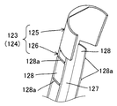
- Each of these harness covers 123 and 124 includes a first cover 125 that is attached to the outer surface of the connectors 150a and 150b of the electrical structure 150, and a second cover that covers the grooves 121 and 122 of the annular covering portion 120a. Part 126 is provided.
- the first harness cover 123 and the second harness cover 124 correspond to the “harness cover” in the present invention.
- each harness cover further includes a cover surface portion 127 having a shape that follows the outer shape surface (occupant facing surface 120b) of the annular covering portion 120a, and the cover surface portion 127 from the back side of the cover surface portion 127.
- a pair of standing portions 128, 128 standing in a crossing manner are provided with a pair of standing portions 128, 128 standing in a crossing manner.
- the cover surface portion 127 referred to here corresponds to a “cover surface portion” in the present invention
- the pair of standing portions 128 and 128 referred to here corresponds to “a pair of standing portions” in the present invention. As shown in FIG.
- a plurality of protruding ribs 128 a extending in the standing direction of the standing part are provided on the outer surface of each standing part 128, and the ribs 128 a are provided on the standing part. Serves as a reinforcing rib.
- the interval between the pair of upright portions 128, 128 is set to an interval corresponding to the groove width of each groove portion of the harness accommodating groove portion, and typically, the pair of upright portions 128, 128 are arranged in the harness accommodating groove portions.
- the first cover portion 125 covers the connectors 150a and 150b of the electrical structure 150
- the second cover portion 126 covers the harness housing groove portion.
- the first groove 121 and the second groove 122 are closed.
- both end portions 127a and 127a of the cover surface portion 127 are in contact with the opening edge portions 120c of the respective groove portions, and a pair of standing portions 128 and 128 inserted into the respective groove portions of the harness housing groove portion. Movement in the groove width direction is restricted.
- the pair of upright portions 128, 128 are in close contact with the groove wall surface by the elastic force in the expanding direction to be separated from each other, and each harness cover is fixed to the harness housing groove portion.
- the harness covers 123 and 124 effective for simply covering the harness 151 for power supply housed in the first groove 121 and the second groove 122 of the harness housing groove are provided.
- the both end portions 127a and 127a of the cover surface portion 127 here correspond to the “end portion of the cover surface portion” in the present invention, and the opening edge portion 120c here is the “opening edge of the harness housing groove portion” in the present invention.
- the part corresponding to the standing part 128 of each harness cover may be omitted, and the part corresponding to the cover surface part 127 may be directly attached to the part corresponding to the annular covering part 120a.
- the mounting structure can also be adopted.
- one or a plurality of interference portions 129 capable of interfering with the harnesses 151a and 151b accommodated in the groove portions 121 and 122 of the annular covering portion 120a are provided.
- the interference portion 129 here corresponds to the “interference portion” in the present invention.
- FIG. 4 the 1st structure which provides the interference part 129 in the site
- the electric supply harness 151 housed in the groove portions 121 and 122 of the annular covering portion 120a is positioned at a predetermined predetermined position while being held or sandwiched from both sides by the plurality of interference portions 129.
- a configuration is preferred.
- a second configuration in which the interference portion 129 is provided in a portion of the annular covering portion 120a facing the harnesses 151a and 151b, and the groove portions 121 and 122 different from the annular covering portion 120a and the harness covers 123 and 124 are disposed.
- a third configuration in which the interference portion 129 is provided in another member, a fourth configuration in which at least two of these first to third configurations are combined, and the like can be used as appropriate.
- the power supply harness 151 (the left harness 151a and the right harness 151b) accommodated in the grooves 121 and 122 of the annular covering part 120a is set in advance by the interference part 129. It can be surely disposed (positioned) at a location. Further, it is effective to prevent the generation of abnormal noise caused by the deviation of the electric supply harness 151, and the disposition of the harness in the harness accommodating groove is more reliable.
- the electric structure 150, the electric supply harness 151, and the power supply relay unit 152 are configured as an assembly that is assembled in advance in an integrated manner. According to such a configuration, the assembly work can be efficiently performed by mounting the entire assembly on the steering wheel 101.
- the harness housing groove portions (the first groove portion 121 and the second groove portion 122) extending in an arc shape along the annular portion 111 of the steering wheel metal core 110 have been described.
- the extending shape of the housing groove portion is not limited to the arc shape, and a configuration in which the harness housing groove portion extends in a curved shape or a straight shape other than the arc shape can also be used.
- the harness accommodation groove part divided into two groove parts the 1st groove part 121 and the 2nd groove part 122, in this invention, it is a single groove part or three or more groove parts. It is also possible to configure a tone storage groove.
- the electric structure 150 is disposed in the annular covering portion 120a among the respective portions of the covering portion 120 has been described.
- the electrical structure 150 may be disposed in a part other than the part 120a, for example, a part corresponding to the spoke part 113.
- the configuration of the steering device of the automobile has been described.
- the present invention can be applied to the configuration of the steering device in all vehicles other than the automobile, for example, buses, taxis, ships, trains, and the like. It is.
- Steering device 101 Steering wheel 110 Steering wheel metal core 111 Annular part 111a Vehicle rear side area 111b Left side area 111c Right side area 111d Vehicle front side area 112 Boss part 113 Spoke part 113a Central spoke part 113b Left spoke part 113c Right spoke part 114 Steering Shaft 120 Covering part 120a Ring covering part 120b Passenger facing surface 120c Opening edge part 121 First groove part 122 Second groove part 123 First harness cover 124 Second harness cover 125 First cover part 126 Second cover part 127 Cover Surface portion 127a End portion 128 Standing portion 129 Interference portion 130 Airbag module 140 Steering wheel skin 150 Electric structure 150a Left side connector 150b Right side connector 151 Electric supply harness 151a Left side harness 151b Right side harness 152 Power relay portion 152a Connector
Abstract
A simplified harness routing structure for routing an electricity supply harness on a steering wheel, the electricity supply harness being used to supply electricity to an electrical structure mounted to the steering wheel.
A steering wheel (101) is provided with a metallic steering wheel core (110) and a cover section (120) for covering the periphery of the steering wheel core (110). The steering wheel core (110) includes a boss section (112), an annular section (111), and a spoke section (113). The cover section (120) includes: an annular cover section (120a) for covering the annular section (111) of the steering wheel core (110); harness containing groove sections (121, 122) for containing an electricity supply harness (151) used for the electrical structure (150) and provided to the cover section (120), the harness containing groove sections being formed in the annular cover section (120a) in the surface (120b) thereof which faces the occupant; and harness covers (123, 124) for covering electricity supply harnesses (151a, 151b) contained in the harness containing groove sections.
Description
本発明は、車両に搭載される車両操舵用のステアリングホイールの構築技術に関するものである。
The present invention relates to a construction technique of a steering wheel for vehicle steering mounted on a vehicle.
従来、例えば下記特許文献1には、車両操舵用のステアリングホイールであって、特に運転者側に電気構造体(表示器)が配置された構成のステアリングホイールが開示されている。特許文献1に記載のこのステアリングホイールでは、ステアリングホイール上の運転者側に表示器が搭載されており、この電気構造体に電気を供給するための電気供給用ハーネスが、被覆層内に埋設された案内筒を通じて表示器に配線されている。
Conventionally, for example, Patent Document 1 below discloses a steering wheel for steering a vehicle, and in particular, a steering wheel having an electric structure (display) arranged on the driver side. In this steering wheel described in Patent Document 1, an indicator is mounted on the driver side on the steering wheel, and an electric supply harness for supplying electricity to the electric structure is embedded in the covering layer. Wired to the display through the guide tube.
ところで、ステアリングホイール上に電気構造体のための電気供給用ハーネスを配線するこの種のステアリングホイールの設計に際しては、例えば特許文献1に記載の案内筒のような別部材を用いることなく簡便に電気供給用ハーネスを配線する技術が要請される。
By the way, when designing this type of steering wheel in which an electric supply harness for an electric structure is wired on the steering wheel, electric power can be simply and without using another member such as a guide cylinder described in Patent Document 1, for example. A technique for wiring the supply harness is required.
そこで、本発明は、かかる点に鑑みてなされたものであり、車両に搭載される車両操舵用のステアリングホイールにおいて、ステアリングホイールに搭載された電気構造体に電気を供給するための電気供給用ハーネスをステアリングホイール上に配線するハーネス配線構造の簡素化を図るのに有効な技術を提供することを課題とする。
Therefore, the present invention has been made in view of the above points, and in a steering wheel for steering a vehicle mounted on a vehicle, an electric supply harness for supplying electricity to an electric structure mounted on the steering wheel. An object of the present invention is to provide a technique effective for simplifying the wiring structure of the harness for wiring the steering wheel on the steering wheel.
前記課題を解決するために、本発明が構成される。なお、本発明は、車両全般に適用することが可能であり、例えば自動車をはじめ、バス、タクシー、船舶、電車等の移動体全般に搭載される車両操舵用のステアリングホイールの構築技術に対し適用され得る。
The present invention is configured to solve the above problems. Note that the present invention can be applied to all vehicles, and is applied to a construction technique for a steering wheel for steering a vehicle that is mounted on a moving body such as an automobile, a bus, a taxi, a ship, and a train. Can be done.
本発明にかかるステアリングホイールは、車両操舵用のステアリングホイールであって、ステアリングホイール芯金、被覆部を少なくとも備える。
A steering wheel according to the present invention is a steering wheel for steering a vehicle, and includes at least a steering wheel mandrel and a covering portion.
ステアリングホイール芯金は、ステアリングホイールのホイール骨格を形成する金属製の芯金部分として構成される。すなわち、このステアリングホイール芯金は、金属材料によってステアリングホイールの芯となる部分に設けられて、ステアリングホイール自体の強度を確保する骨格部分として構成される部材である。このステアリングホイール芯金は、ボス部、環状部、スポーク部を少なくとも有する。ボス部は、ステアリングホイール芯金の各部位のうち当該ステアリングホイール芯金とステアリングシャフトとを連結する部位として構成される。環状部は、ステアリングホイール芯金の各部位のうち環状に構成される部位として構成され、典型的には円環状として構成される。なお、ステアリングホイールの形状によっては、楕円形ないし多角形の環状としてこの環状部を構成することもできる。スポーク部は、ステアリングホイール芯金の各部位のうちボス部と環状部を連結する部位として構成される。
Steering wheel core metal is configured as a metal core metal part that forms the wheel skeleton of the steering wheel. In other words, the steering wheel core is a member that is provided at a portion that becomes a core of the steering wheel by a metal material and is configured as a skeleton portion that ensures the strength of the steering wheel itself. This steering wheel metal core has at least a boss part, an annular part, and a spoke part. A boss | hub part is comprised as a site | part which connects the said steering wheel metal core and a steering shaft among each site | part of a steering wheel metal core. The annular portion is configured as a portion configured in an annular shape among the respective portions of the steering wheel core, and is typically configured as an annular shape. Depending on the shape of the steering wheel, the annular portion can be configured as an elliptical or polygonal ring. A spoke part is comprised as a site | part which connects a boss | hub part and an annular part among each site | part of a steering wheel metal core.
被覆部は、ステアリングホイール芯金の周囲を被覆する部位とされ、環状被覆部、ハーネス収容溝部及びハーネスカバーを含む。環状被覆部は、ステアリングホイール芯金のうちの環状部を被覆する部位として構成される。この環状被覆部は、典型的にはポリプロピレン(PP)樹脂、アクリロニトリル・ブタジエン・スチレン(ABS)樹脂、ウレタン樹脂等の工業樹脂によって形成される。ハーネス収容溝部は、被覆部に配設される電気構造体のための電気供給用ハーネスを収容するために環状被覆部の乗員対向面に溝状に形成された溝部分として構成される。環状被覆部の乗員対向面は、ステアリングホイールの車両搭載時に乗員に向かう面であって、環状被覆部の各部位のうちステアリングホイール芯金の環状部とは反対側の領域としても規定される。なお、電気構造体は、被覆部に配設される構成とされ、被覆部の各部位のうち環状被覆部に配設されてもよいし、或いは環状被覆部以外の部位に配設されてもよい。ハーネスカバーは、ハーネス収容溝部に収容された電気供給用ハーネスを覆うハーネスカバー部分として構成される。本発明において、電気構造体や電気供給用ハーネスは、ステアリングホイールの一構成要素とされてもよいし、或いはステアリングホイールとは別の構成要素とされてもよい。
The covering portion is a portion covering the periphery of the steering wheel core, and includes an annular covering portion, a harness receiving groove portion, and a harness cover. The annular covering portion is configured as a portion that covers the annular portion of the steering wheel core metal. The annular covering portion is typically formed of an industrial resin such as polypropylene (PP) resin, acrylonitrile / butadiene / styrene (ABS) resin, urethane resin or the like. The harness housing groove portion is configured as a groove portion formed in a groove shape on the occupant-facing surface of the annular covering portion in order to accommodate an electrical supply harness for the electrical structure disposed in the covering portion. The occupant-facing surface of the annular covering portion is a surface that faces the occupant when the steering wheel is mounted on a vehicle, and is also defined as a region on the opposite side of the annular portion of the steering wheel metal core from each part of the annular covering portion. The electrical structure is configured to be disposed on the covering portion, and may be disposed on the annular covering portion among the portions of the covering portion, or may be disposed on a portion other than the annular covering portion. Good. A harness cover is comprised as a harness cover part which covers the harness for electric supply accommodated in the harness accommodating groove part. In the present invention, the electric structure and the electric supply harness may be a component of the steering wheel or may be a component different from the steering wheel.
本発明にかかるステアリングホイールの上記構成によれば、環状被覆部自体にハーネス収容溝部を直に設けることによって、電気供給用ハーネスの配線のための部材を新たに設ける必要がなく、ハーネス配線構造を簡素化することが可能となる。このとき、環状被覆部が、ステアリングホイール芯金の環状部を被覆する機能と、電気構造体に電気を供給するための電気供給用ハーネスを配線する機能を兼務することとなり合理的である。また、樹脂成型時に環状被覆部にハーネス収容溝部を設けることで、ハーネスの形状や大きさに見合ったハーネス収容溝部を簡便に形成することが可能となる。
According to the above configuration of the steering wheel according to the present invention, it is not necessary to newly provide a member for wiring of the harness for supplying electricity by directly providing the harness receiving groove portion in the annular covering portion itself, and the harness wiring structure It becomes possible to simplify. At this time, the annular covering portion serves both as a function of covering the annular portion of the steering wheel core and a function of wiring an electric supply harness for supplying electricity to the electric structure. Further, by providing the harness housing groove in the annular covering portion during resin molding, it is possible to easily form the harness housing groove corresponding to the shape and size of the harness.
また、本発明にかかる更なる形態のステアリングホイールでは、前記のハーネス収容溝部は、電気構造体に対応する部位(「第1の部位」ともいう)とスポーク部に対応する部位(「第2の部位」ともいう)との間をステアリングホイール芯金の環状部に沿って円弧状に延在する円弧状溝部を含む構成であるのが好ましい。このハーネス収容溝部は、第1の部位と第2の部位との間を延在する溝部を少なくとも有していれば良く、当該溝部のみのよってハーネス収容溝部が構成されてもよいし、或いは当該溝部に更なる別の経路に延在する溝部を加えてハーネス収容溝部が構成されてもよい。このような構成によれば、スポーク部に対応する第2の部位から導入された電気供給用ハーネスを、ステアリングホイール芯金の環状部に沿って電気構造体に対応する第1の部位へと円弧状に延在させることが可能となる。
Moreover, in the steering wheel of the further form concerning this invention, the said harness accommodating groove part is a site | part (it is also called a "1st site | part") corresponding to an electrical structure, and a site | part ("2nd 2nd" It is preferable to include an arc-shaped groove portion extending in an arc shape along the annular portion of the steering wheel metal core. The harness housing groove may only have at least a groove extending between the first part and the second part, and the harness housing groove may be constituted only by the groove, or The harness accommodating groove may be configured by adding a groove extending in another path to the groove. According to such a configuration, the electric supply harness introduced from the second portion corresponding to the spoke portion is circularly transferred to the first portion corresponding to the electric structure along the annular portion of the steering wheel core metal. It becomes possible to extend in an arc.
また、本発明にかかる更なる形態のステアリングホイールでは、前記の円弧状溝部は、スポーク部に対応する部位から環状部に沿って時計回りに円弧状に延在する第1の溝部と、スポーク部に対応する部位から環状部に沿って反時計回りに円弧状に延在する第2の溝部とに区画された構成であるのが好ましい。このような構成によれば、スポーク部に対応する第2の部位から導入された複数の電気供給用ハーネスを、第1の溝部側と第2の溝部側に分岐させたうえで、分岐した電気供給用ハーネスをそれぞれ各溝部によって電気構造体に対応する第1の部位へと延在させることが可能となる。このとき、第1の溝部を延在した電気供給用ハーネスと第2の溝部を延在した電気供給用ハーネスは、単一(同一)の電気構造体に接続される構成であってもよいし、或いは互いに異なる電気構造体に接続される構成であってもよい。
Moreover, in the steering wheel of the further form concerning this invention, the said circular arc-shaped groove part is a 1st groove part extended in circular arc shape clockwise along an annular part from the site | part corresponding to a spoke part, and a spoke part. Is preferably divided into a second groove portion extending in an arc shape in a counterclockwise direction along the annular portion. According to such a configuration, the plurality of electric supply harnesses introduced from the second part corresponding to the spoke part are branched into the first groove part side and the second groove part side, and then the branched electricity is supplied. The supply harness can be extended to the first portion corresponding to the electric structure by the respective groove portions. At this time, the electric supply harness extending the first groove and the electric supply harness extending the second groove may be connected to a single (same) electric structure. Alternatively, it may be configured to be connected to different electrical structures.
また、本発明にかかる更なる形態のステアリングホイールでは、前記のハーネスカバーは、カバー表面部及び一対の立設部を含む構成であるのが好ましい。カバー表面部は、環状被覆部の外形面に倣った形状を有する部位として構成される。一対の立設部は、カバー表面部の裏側からそれぞれ並行状に立設するとともにハーネス収容溝部の溝幅に対応した間隔に設定された部位として構成される。そして、このハーネスカバーは、ハーネスカバー装着時に一対の立設部がハーネス収容溝部に挿設され、且つカバー表面部の端部がハーネス収容溝部の開口縁部に当接する。このような構成によれば、ハーネス収容溝部に収容された電気供給用ハーネスを簡便に覆うのに有効なハーネスカバーが提供される。
Moreover, in the steering wheel of the further form concerning this invention, it is preferable that the said harness cover is a structure containing a cover surface part and a pair of standing part. A cover surface part is comprised as a site | part which has the shape which followed the external shape surface of the cyclic | annular coating | coated part. The pair of standing portions are configured as portions that are set up in parallel from the back side of the cover surface portion and are set at intervals corresponding to the groove width of the harness housing groove portion. In the harness cover, when the harness cover is mounted, the pair of standing portions are inserted into the harness housing groove, and the end of the cover surface portion abuts against the opening edge of the harness housing groove. According to such a configuration, a harness cover effective for simply covering the harness for supplying electricity housed in the harness housing groove is provided.
また、本発明にかかる更なる形態のステアリングホイールでは、前記のハーネスカバー及び前記の環状被覆部の少なくとも一方は、ハーネス収容溝部に収容された電気供給用ハーネスに干渉する干渉部を備える構成であるのが好ましい。このとき、ハーネス収容溝部に収容された電気供給用ハーネスは、複数の干渉部によって両側から保持ないし挟持されつつ予め設定された既定箇所に位置決めされる構成であるのが好ましい。このような構成によれば、ハーネス収容溝部に収容された電気供給用ハーネスを、干渉部によって予め設定された既定箇所に確実に配設する(位置決めする)ことができるとともに、ハーネス収容溝部に収容された電気供給用ハーネスが干渉部に干渉することによって、電気供給用ハーネスのズレによって生じる異音の発生を防止するのに有効である。従って、ハーネス配線構造の簡素化を図ることが可能となる上に、更にハーネス収容溝部にハーネスを確実に配設することが可能となる。
Moreover, in the steering wheel of the further form concerning this invention, it is the structure provided with the interference part which interferes with the harness for electrical supply accommodated in the harness accommodating groove part at least one of the said harness cover and the said cyclic | annular coating | coated part. Is preferred. At this time, it is preferable that the electricity supply harness housed in the harness housing groove is positioned at a predetermined position while being held or sandwiched from both sides by a plurality of interference parts. According to such a configuration, the harness for supplying electricity housed in the harness housing groove can be reliably disposed (positioned) at a predetermined location set in advance by the interference section, and is housed in the harness housing groove. It is effective to prevent the generation of abnormal noise caused by the deviation of the electric supply harness by the interference of the electric supply harness that has been made. Therefore, it is possible to simplify the harness wiring structure, and it is possible to reliably arrange the harness in the harness housing groove.
本発明にかかるステアリング装置は、車両操舵用のステアリングホイールと、ステアリングホイールの外形内に配設され、車両衝突時に乗員拘束領域に展開膨張するエアバッグによって車両乗員を拘束するエアバッグモジュールとを備える構成である。特にこのステアリング装置のステアリングホイールは、前述の各形態のステアリングホイールを用いて構成される。従って、本発明によれば、電気構造体に電気を供給するための電気供給用ハーネスのハーネス配線構造が簡素化されたステアリングホイールを備えるステアリング装置が提供される。
A steering apparatus according to the present invention includes a steering wheel for steering a vehicle, and an airbag module that is disposed within an outer shape of the steering wheel and restrains a vehicle occupant by an airbag that is deployed and inflated in an occupant restraint region in the event of a vehicle collision. It is a configuration. In particular, the steering wheel of the steering device is configured using the steering wheel of each of the above-described forms. Therefore, according to the present invention, there is provided a steering apparatus including a steering wheel in which a harness wiring structure of an electrical supply harness for supplying electricity to an electrical structure is simplified.
以上のように、本発明によれば、車両操舵用のステアリングホイールにおいて、特にステアリングホイール芯金の環状部を被覆する環状被覆部に、電気構造体に電気を供給するための電気供給用ハーネスを配線するハーネス収容溝部を設ける構造を採用することによって、ハーネス配線構造の簡素化を図ることが可能となる。
As described above, according to the present invention, in the steering wheel for steering a vehicle, an electrical supply harness for supplying electricity to the electrical structure is provided particularly on the annular covering portion that covers the annular portion of the steering wheel core metal. By adopting a structure in which a harness receiving groove for wiring is provided, the harness wiring structure can be simplified.
以下、本発明にかかる「ステアリング装置」の一実施の形態であるステアリング装置100の構造を、図面を参照しつつ説明する。このステアリング装置100の全体的な構成に関しては図1及び図2が参照される。ここで、図1には本実施の形態のステアリング装置100の平面図が示されており、また図2には、図1中のステアリングホイール101のハーネスカバー123,124が取り外された状態の平面図が示されている。
Hereinafter, the structure of the steering device 100 as an embodiment of the “steering device” according to the present invention will be described with reference to the drawings. 1 and 2 are referred to regarding the overall configuration of the steering device 100. FIG. Here, FIG. 1 shows a plan view of the steering device 100 of the present embodiment, and FIG. 2 shows a plan view of the steering wheel 101 in FIG. 1 with the harness covers 123 and 124 removed. The figure is shown.
図1に示すように、ステアリング装置100は、運転者が車両操舵に用いる車両操舵用のステアリングホイール101を備える。このステアリングホイール101は、その構成要素がステアリングホイール芯金110及び被覆部120に大別される。また、このステアリング装置100は、ステアリングホイール101の外形内に、所定の態様で折り畳まれたエアバッグがガス供給によって展開膨張する構成のエアバッグモジュール130が装着される。このエアバッグモジュール130は、車両衝突時に乗員拘束領域に展開膨張するエアバッグによって車両乗員を拘束する機能を果たす。ここでいうステアリングホイール101及びエアバッグモジュール130がそれぞれ、本発明における「ステアリングホイール」及び「エアバッグモジュール」に相当する。
As shown in FIG. 1, the steering device 100 includes a steering wheel 101 for steering a vehicle that is used by the driver for steering the vehicle. The components of the steering wheel 101 are roughly divided into a steering wheel core 110 and a covering portion 120. In addition, in the steering device 100, an airbag module 130 having a configuration in which an airbag folded in a predetermined manner is deployed and inflated by gas supply is mounted in the outer shape of the steering wheel 101. The airbag module 130 functions to restrain a vehicle occupant with an airbag that is deployed and inflated in the occupant restraint region in the event of a vehicle collision. The steering wheel 101 and the airbag module 130 here correspond to the “steering wheel” and the “airbag module” in the present invention, respectively.
ステアリングホイール芯金110は、ステアリングホイール101のホイール骨格を形成する金属製の芯金部分である。このステアリングホイール芯金110は、ステアリングホイール101の芯となる部分に設けられて、ステアリングホイール101自体の強度を確保する骨格部分として構成される。このステアリングホイール芯金110は、円環状に構成される環状部111、ボス部112及びスポーク部113を少なくとも備え、典型的には1または複数のシェル部材によって構成される。ここでいうステアリングホイール芯金110が、本発明における「ステアリングホイール芯金」に相当する。
The steering wheel core 110 is a metal core that forms the wheel skeleton of the steering wheel 101. The steering wheel mandrel 110 is provided as a core part of the steering wheel 101 and is configured as a skeleton part that ensures the strength of the steering wheel 101 itself. The steering wheel metal core 110 includes at least an annular portion 111, a boss portion 112, and a spoke portion 113 configured in an annular shape, and is typically configured by one or a plurality of shell members. The steering wheel metal core 110 here corresponds to the “steering wheel metal core” in the present invention.
環状部111は、ステアリングホイール芯金110においてホイール外形を規定するべく環状に形成された部位として構成されている。ボス部112は、ステアリングホイール芯金110の中央領域において、車両操舵軸としてのステアリングシャフト(図示省略)に連結される部位として構成される。スポーク部113は、環状部111とボス部112とを連結する部位として構成される。図1では、環状部111のうち車両後方側領域111aとボス部112とを連結する中央スポーク部113aと、環状部111のうちの左側領域111bとボス部112とを連結する左スポーク部113bと、環状部111のうちの右側領域111cとボス部112とを連結する右スポーク部113cの計3つのスポーク部を備える場合について記載している。ここでいう環状部111、ボス部112及びスポーク部113がそれぞれ、本発明における「環状部」、「ボス部」及び「スポーク部」に相当する。
The annular portion 111 is configured as a portion formed in an annular shape in the steering wheel core 110 so as to define the outer shape of the wheel. The boss 112 is configured as a portion connected to a steering shaft (not shown) as a vehicle steering shaft in the central region of the steering wheel core 110. The spoke part 113 is configured as a part connecting the annular part 111 and the boss part 112. In FIG. 1, a central spoke portion 113 a that connects the vehicle rear side region 111 a and the boss portion 112 in the annular portion 111, and a left spoke portion 113 b that connects the left region 111 b of the annular portion 111 and the boss portion 112. The case where a total of three spoke portions including a right spoke portion 113c that connects the right region 111c and the boss portion 112 of the annular portion 111 is described. The annular portion 111, the boss portion 112, and the spoke portion 113 referred to here correspond to the “annular portion”, the “boss portion”, and the “spoke portion” in the present invention, respectively.
なお、ステアリング装置100は、車両に装着された状態では、ステアリングホイール101の延在平面が車両前方へと傾斜する。これにより通常操舵位置ではステアリングホイール101のうち時計の「12時」に対応する部位が車両前方側領域となり、またステアリングホイール101のうち時計の「6時」に相当する部位が車両後方側領域となる。従って、本明細書では、ステアリング装置100が車両に装着された状態の通常操舵位置(直進操舵位置)において、最も車両後方側に位置する部位、すなわち図1及び図2中のステアリング装置100の下側を「車両後方側領域」といい、また最も車両前方側に位置する部位、すなわち図1及び図2中のステアリング装置100の上側を「車両前方側領域」という。
In the state where steering device 100 is mounted on the vehicle, the extending plane of steering wheel 101 is inclined forward of the vehicle. As a result, at the normal steering position, a portion of the steering wheel 101 corresponding to “12 o'clock” of the timepiece becomes the vehicle front side region, and a portion of the steering wheel 101 corresponding to “6 o'clock” of the timepiece becomes the vehicle rear side region. Become. Therefore, in the present specification, in a normal steering position (straight-ahead steering position) in a state where the steering device 100 is mounted on the vehicle, a portion located on the most rear side of the vehicle, that is, below the steering device 100 in FIGS. The side is referred to as a “vehicle rear side region”, and the portion located on the most front side of the vehicle, that is, the upper side of the steering device 100 in FIGS.
ステアリングホイール101の被覆部120は、ステアリングホイール芯金110を被覆する樹脂材料製の被覆部として構成される。この被覆部120は、環状被覆部120aと、ハーネス収容溝部(後述する第1及び第2の溝部121,122からなるハーネス収容溝部)と、ハーネスカバー(後述する第1及び第2のハーネスカバー123,124からなるハーネスカバー)を少なくとも含む構成である。また、この被覆部120の表面には、本革、合成皮革、金属板、織布、織物、樹脂板、ゴムシート等からなるステアリングホイール表皮140が適宜に接合されて加飾が行なわれる。ここでいう被覆部120が、本発明における「被覆部」に相当する。
The covering portion 120 of the steering wheel 101 is configured as a covering portion made of a resin material that covers the steering wheel core 110. The covering portion 120 includes an annular covering portion 120a, a harness receiving groove portion (a harness receiving groove portion including first and second groove portions 121 and 122 described later), and a harness cover (first and second harness covers 123 described later). , 124). Further, a steering wheel skin 140 made of genuine leather, synthetic leather, metal plate, woven fabric, woven fabric, resin plate, rubber sheet or the like is appropriately joined to the surface of the covering portion 120 for decoration. The covering portion 120 here corresponds to the “covering portion” in the present invention.
環状被覆部120aは、ステアリングホイール芯金110のうちの環状部111を被覆する被覆部として構成される。この環状被覆部120aは、典型的には、ポリプロピレン(PP)樹脂、アクリロニトリル・ブタジエン・スチレン(ABS)樹脂、ウレタン樹脂等の工業樹脂によって形成される。ここでいう環状被覆部120aが、本発明における「環状被覆部」に相当する。
The annular covering portion 120 a is configured as a covering portion that covers the annular portion 111 of the steering wheel core 110. The annular covering portion 120a is typically formed of an industrial resin such as a polypropylene (PP) resin, an acrylonitrile / butadiene / styrene (ABS) resin, or a urethane resin. The annular covering portion 120a here corresponds to the “annular covering portion” in the present invention.
本実施の形態では、ステアリングホイール101上の乗員側(環状被覆部120aの乗員対向面120b)に電気構造体150が搭載されている。この電気構造体150として、電気供給によって所定の情報を表示可能な表示部材、電気供給によって発光が可能な発光部材、また電気供給によってスイッチ操作が可能であるスイッチ部材等を好適に用いる。この電気構造体150は、特に環状被覆部120aの乗員対向面120bのうち車両前方側領域111dにおいてスポーク部113に対し取り付け固定される。また、本実施の形態では、この電気構造体150に対し電気を供給するための電気供給用ハーネス151が設けられている。
In the present embodiment, the electric structure 150 is mounted on the occupant side (the occupant facing surface 120b of the annular covering portion 120a) on the steering wheel 101. As the electric structure 150, a display member capable of displaying predetermined information by electric supply, a light emitting member capable of emitting light by electric supply, a switch member capable of switching operation by electric supply, and the like are preferably used. This electric structure 150 is attached and fixed to the spoke portion 113 particularly in the vehicle front side region 111d of the passenger facing surface 120b of the annular covering portion 120a. In the present embodiment, an electrical supply harness 151 for supplying electricity to the electrical structure 150 is provided.
図2に示すように、この電気供給用ハーネス151は、バッテリ側に接続された電源中継部152と電気構造体150との間で長尺状に延在するハーネス部材として構成されている。具体的には、電源中継部152のコネクタ152aから延出したのち、スポーク部113の環状部111のうちの車両後方側領域111aを経て、ステアリングホイール101上を車両前方側領域111dに向けてそれぞれ配線される左側ハーネス151a及び右側ハーネス151bを備える。
As shown in FIG. 2, the electric supply harness 151 is configured as a harness member extending in a long shape between the power supply relay unit 152 connected to the battery side and the electric structure 150. Specifically, after extending from the connector 152a of the power relay part 152, the vehicle wheel side region 111a of the annular part 111 of the spoke part 113 is passed through the steering wheel 101 toward the vehicle front side region 111d. A left harness 151a and a right harness 151b to be wired are provided.
一方、ハーネス収容溝部は、電気構造体150のための電気供給用ハーネス151を収容するべく環状被覆部120aの乗員対向面120bに溝状に形成されており、電気構造体150に対応する部位とスポーク部113に対応する部位との間をステアリングホイール芯金110の環状部111に沿って円弧状に延在する円弧状溝部として構成される。これにより、中央スポーク部113aに対応する部位から導入された電気供給用ハーネス151は、ステアリングホイール芯金110の環状部111に沿って電気構造体150に対応する部位へと円弧状に延在することが可能となる。
On the other hand, the harness housing groove is formed in a groove shape on the occupant-facing surface 120b of the annular covering portion 120a so as to accommodate the electrical supply harness 151 for the electrical structure 150, and a portion corresponding to the electrical structure 150 A portion corresponding to the spoke portion 113 is formed as an arc-shaped groove portion extending in an arc shape along the annular portion 111 of the steering wheel core 110. Thus, the electric supply harness 151 introduced from the portion corresponding to the central spoke portion 113a extends in an arc shape along the annular portion 111 of the steering wheel core 110 to the portion corresponding to the electric structure 150. It becomes possible.
このハーネス収容溝部は、第1の溝部121と第2の溝部122とに区画されている。第1の溝部121は、中央スポーク部113aに対応する部位から、環状被覆部120aの乗員対向面120bのうちステアリングホイール芯金110の環状部111の左側部分に沿って時計回りに円弧状に形成されて、電気供給用ハーネス151の左側ハーネス151aを収容するハーネス収容溝部として構成される。また、第2の溝部122は、中央スポーク部113aに対応する部位から、環状被覆部120aの乗員対向面120bのうちステアリングホイール芯金110の環状部111の右側部分に沿って反時計回りに円弧状に形成されて、電気供給用ハーネス151の右側ハーネス151bを収容するハーネス収容溝部として構成される。これにより、中央スポーク部113aに対応する部位から導入された2つのハーネス151a,151bを、第1の溝部121側と第2の溝部122側に分岐させたうえで、分岐したハーネス151a,151bをそれぞれ各溝部によって電気構造体150に対応する部位へと延在させることが可能となる。
The harness housing groove is partitioned into a first groove 121 and a second groove 122. The first groove portion 121 is formed in a circular arc shape clockwise from the portion corresponding to the central spoke portion 113a along the left side portion of the annular portion 111 of the steering wheel core 110 on the occupant facing surface 120b of the annular covering portion 120a. Thus, it is configured as a harness housing groove for housing the left harness 151a of the electrical supply harness 151. Further, the second groove portion 122 is circularly counterclockwise from the portion corresponding to the central spoke portion 113a along the right side portion of the annular portion 111 of the steering wheel core 110 on the occupant facing surface 120b of the annular covering portion 120a. It is formed in an arc shape and is configured as a harness housing groove that houses the right harness 151b of the electrical supply harness 151. Thereby, after branching the two harnesses 151a and 151b introduced from the part corresponding to the central spoke part 113a into the first groove part 121 side and the second groove part 122 side, the branched harnesses 151a and 151b are connected. Each groove portion can be extended to a portion corresponding to the electric structure 150.
そして、第1の溝部121を図2中の時計回りに電気構造体150に向けて延在した左側ハーネス151aは、電気構造体150の左側の左側コネクタ150aに結線される。また第2の溝部122を図2中の反時計回りに電気構造体150に向けて延在した右側ハーネス151bは、電気構造体150の右側の右側コネクタ150bに結線される。このように、本実施の形態では、左側ハーネス151a及び右側ハーネス151bは、いずれも単一(同一の)の電気構造体150に結線されている。ここでいう第1の溝部121が本発明における「第1の溝部」に相当し、第2の溝部122が本発明における「第2の溝部」に相当する。またこれら第1の溝部121及び第2の溝部122からなるハーネス収容溝部が、本発明における「ハーネス収容溝部」を構成している。
Then, the left harness 151a in which the first groove 121 extends in the clockwise direction in FIG. 2 toward the electric structure 150 is connected to the left connector 150a on the left side of the electric structure 150. Also, the right harness 151 b that extends the second groove 122 in the counterclockwise direction in FIG. 2 toward the electric structure 150 is connected to the right connector 150 b on the right side of the electric structure 150. Thus, in the present embodiment, both the left harness 151a and the right harness 151b are connected to a single (same) electrical structure 150. Here, the first groove 121 corresponds to the “first groove” in the present invention, and the second groove 122 corresponds to the “second groove” in the present invention. In addition, the harness housing groove portion including the first groove portion 121 and the second groove portion 122 constitutes the “harness housing groove portion” in the present invention.
なお、本実施の形態において、電源中継部152は、バッテリ電源からの電気を電気構造体150に供給するとともに、この電気構造体150の制御をあわせて行なう制御回路を含む制御部として構成されてもよい。或いはバッテリ電源からの電気を単に電気構造体150に分配する部位として構成されてもよい。
In the present embodiment, power supply relay unit 152 is configured as a control unit including a control circuit that supplies electricity from battery power to electric structure 150 and also controls electric structure 150. Also good. Or you may be comprised as a site | part which distributes the electricity from a battery power supply to the electric structure 150 only.
上記環状被覆部120aのハーネス収容溝部における電気供給用ハーネス151の収容構造に関しては、図3~図5が参照される。なお、第1の溝部121及び第2の溝部122は同様の構成を有するため、ここでは第1の溝部121を例にして説明する。図3には、図2中のステアリングホイール101のB-B線に関する断面構造がハーネスカバー未装着状態にて示されており、図4には、図1中のステアリングホイール101のA-A線に関する断面構造がハーネスカバー装着状態にて示されている。また、図5には、図2中の環状被覆部120aに対し装着されるハーネスカバー123,124の部分斜視図が示されている。
Referring to FIGS. 3 to 5 for the housing structure of the electricity supply harness 151 in the harness housing groove of the annular covering portion 120a. Since the first groove 121 and the second groove 122 have the same configuration, the first groove 121 will be described as an example here. 3 shows a cross-sectional structure of the steering wheel 101 taken along line BB in FIG. 2 in a state in which the harness cover is not attached. FIG. 4 shows an AA line of the steering wheel 101 in FIG. The cross-sectional structure is shown with the harness cover attached. FIG. 5 is a partial perspective view of harness covers 123 and 124 attached to the annular covering portion 120a in FIG.
図3に示すように、電気供給用ハーネス151の左側ハーネス151aを収容する第1の溝部121は、環状被覆部120aの断面構造に関し、乗員対向面120bが内方に向けて凹状に凹んだ溝部分として構成される。この第1の溝部121は、左側ハーネス151aの断面径よりも大きな溝幅及び溝深さを有する。このような構成によれば、環状被覆部120a自体にハーネス収容溝部を直に設けることによって、ハーネス配線のための部材を新たに設ける必要がなく、ハーネス配線構造を簡素化することが可能となる。このとき、環状被覆部120aが、ステアリングホイール芯金110の環状部111を被覆する機能と、電気構造体150に電気を供給するための電気供給用ハーネス151を配線する機能を兼務することとなり合理的である。また、樹脂成型時に環状被覆部120aにハーネス収容溝部を設けることで、電気供給用ハーネス151の形状や大きさに見合ったハーネス収容溝部を簡便に形成することが可能となる。
As shown in FIG. 3, the first groove 121 that accommodates the left harness 151a of the electric supply harness 151 is a groove in which the occupant-facing surface 120b is recessed inwardly with respect to the cross-sectional structure of the annular covering portion 120a. Configured as part. The first groove 121 has a larger groove width and depth than the cross-sectional diameter of the left harness 151a. According to such a configuration, it is not necessary to newly provide a member for harness wiring by directly providing the harness housing groove portion in the annular covering portion 120a itself, and the harness wiring structure can be simplified. . At this time, the annular covering portion 120a has both a function of covering the annular portion 111 of the steering wheel core 110 and a function of wiring the electric supply harness 151 for supplying electricity to the electric structure 150. Is. Further, by providing the harness housing groove in the annular covering portion 120a at the time of resin molding, it is possible to easily form the harness housing groove corresponding to the shape and size of the electricity supply harness 151.
また、図4及び図5に示すように、本実施の形態のステアリングホイール101では、ハーネス収容溝部(第1の溝部121及び第2の溝部122)に対応したハーネスカバー123,124が設けられている。これらハーネスカバー123,124は、ハーネス収容溝部に収容された電気供給用ハーネス151(左側ハーネス151a及び右側ハーネス151b)を覆うとともに、ハーネス収容溝部をカバーして断面凹状の溝部分を埋めることによって意匠を確保する機能を果たす。これらハーネスカバー123,124は、環状被覆部120aと同様の、ポリプロピレン(PP)樹脂、アクリロニトリル・ブタジエン・スチレン(ABS)樹脂、ウレタン樹脂等の工業樹脂、或いはゴム材料によって形成され得る。
As shown in FIGS. 4 and 5, the steering wheel 101 of the present embodiment is provided with harness covers 123 and 124 corresponding to the harness housing groove portions (the first groove portion 121 and the second groove portion 122). Yes. These harness covers 123 and 124 cover the harness 151 for electricity supply housed in the harness housing groove (the left harness 151a and the right harness 151b) and cover the harness housing groove to fill the groove section having a concave cross section. Fulfill the function of ensuring. These harness covers 123 and 124 may be formed of an industrial resin such as polypropylene (PP) resin, acrylonitrile butadiene styrene (ABS) resin, urethane resin, or a rubber material, similar to the annular covering portion 120a.
第1のハーネスカバー123が、環状被覆部120aの乗員対向面120bのうち第1の溝部121に対応した部位に装着され、また第2のハーネスカバー124が、環状被覆部120aの乗員対向面120bのうち第2の溝部122に対応した部位に装着される。環状被覆部120aの乗員対向面120bは、ステアリングホイールの車両搭載時に乗員に向かう面であって、環状被覆部120aの各部位のうちステアリングホイール芯金110の環状部111とは反対側の領域としても規定される。これらハーネスカバー123,124はいずれも、電気構造体150のコネクタ150a,150bの外面に被着される第1カバー部125と、環状被覆部120aの溝部121,122を塞ぐように覆う第2カバー部126を備える。ここでいう第1のハーネスカバー123及び第2のハーネスカバー124が、本発明における「ハーネスカバー」に相当する。
The first harness cover 123 is attached to a portion corresponding to the first groove 121 in the occupant facing surface 120b of the annular covering portion 120a, and the second harness cover 124 is attached to the occupant facing surface 120b of the annular covering portion 120a. Are attached to the portion corresponding to the second groove 122. An occupant-facing surface 120b of the annular covering portion 120a is a surface that faces the occupant when the steering wheel is mounted on a vehicle, and is an area on the opposite side of the annular portion 111 of the steering wheel core 110 from each part of the annular covering portion 120a. Is also defined. Each of these harness covers 123 and 124 includes a first cover 125 that is attached to the outer surface of the connectors 150a and 150b of the electrical structure 150, and a second cover that covers the grooves 121 and 122 of the annular covering portion 120a. Part 126 is provided. Here, the first harness cover 123 and the second harness cover 124 correspond to the “harness cover” in the present invention.
各ハーネスカバーの第2カバー部126は、更に環状被覆部120aの外形面(乗員対向面120b)に倣った形状を有するカバー表面部127と、このカバー表面部127の裏側から当該カバー表面部127に対し交差状に立設する一対の立設部128,128を備える。ここでいうカバー表面部127が、本発明における「カバー表面部」に相当し、またここでいう一対の立設部128,128が、本発明における「一対の立設部」に相当する。各立設部128の外面には、図5に示すように、当該立設部の立設方向に延在する突状のリブ128aが複数設けられており、このリブ128aが当該立設部の補強用のリブとしての機能を果たす。一対の立設部128,128の間隔は、ハーネス収容溝部の各溝部の溝幅に対応した間隔に設定されており、典型的には、一対の立設部128,128がハーネス収容溝部の各溝部に挿入されたときに、各立設部の外面が溝部壁面に密着状に当接するように設定される。
The second cover portion 126 of each harness cover further includes a cover surface portion 127 having a shape that follows the outer shape surface (occupant facing surface 120b) of the annular covering portion 120a, and the cover surface portion 127 from the back side of the cover surface portion 127. Are provided with a pair of standing portions 128, 128 standing in a crossing manner. The cover surface portion 127 referred to here corresponds to a “cover surface portion” in the present invention, and the pair of standing portions 128 and 128 referred to here corresponds to “a pair of standing portions” in the present invention. As shown in FIG. 5, a plurality of protruding ribs 128 a extending in the standing direction of the standing part are provided on the outer surface of each standing part 128, and the ribs 128 a are provided on the standing part. Serves as a reinforcing rib. The interval between the pair of upright portions 128, 128 is set to an interval corresponding to the groove width of each groove portion of the harness accommodating groove portion, and typically, the pair of upright portions 128, 128 are arranged in the harness accommodating groove portions. When inserted into the groove portion, the outer surface of each standing portion is set so as to come into close contact with the wall surface of the groove portion.
このような構成により、各ハーネスカバーが装着されたハーネスカバー装着時には、第1カバー部125によって電気構造体150のコネクタ150a,150bが被覆されるとともに、第2カバー部126によってハーネス収容溝部の第1の溝部121及び第2の溝部122が塞がれる。第2カバー部126では、カバー表面部127の両端部127a,127aが、各溝部の開口縁部120cに当接するとともに、ハーネス収容溝部の各溝部に挿入された一対の立設部128,128によって溝幅方向の移動が規制される。このとき、一対の立設部128,128が互いに離間する拡径方向の弾発力によって溝部壁面に密着状に当接して、各ハーネスカバーがハーネス収容溝部に止着される構成であるのが好ましい。従って、本実施の形態によれば、ハーネス収容溝部の第1の溝部121及び第2の溝部122に収容された電気供給用ハーネス151を簡便に覆うのに有効なハーネスカバー123,124が提供される。ここでいうカバー表面部127の両端部127a,127aが、本発明における「カバー表面部の端部」に相当し、またここでいう開口縁部120cが、本発明における「ハーネス収容溝部の開口縁部」に相当する。なお、必要に応じ、各ハーネスカバーの立設部128に相当する部位を省略して、カバー表面部127に相当する部位を、環状被覆部120aに相当する部位に直接的に取り付ける構成や、その他の取り付け構造を採用することもできる。
With this configuration, when the harness cover is mounted with each harness cover, the first cover portion 125 covers the connectors 150a and 150b of the electrical structure 150, and the second cover portion 126 covers the harness housing groove portion. The first groove 121 and the second groove 122 are closed. In the second cover portion 126, both end portions 127a and 127a of the cover surface portion 127 are in contact with the opening edge portions 120c of the respective groove portions, and a pair of standing portions 128 and 128 inserted into the respective groove portions of the harness housing groove portion. Movement in the groove width direction is restricted. At this time, the pair of upright portions 128, 128 are in close contact with the groove wall surface by the elastic force in the expanding direction to be separated from each other, and each harness cover is fixed to the harness housing groove portion. preferable. Therefore, according to the present embodiment, the harness covers 123 and 124 effective for simply covering the harness 151 for power supply housed in the first groove 121 and the second groove 122 of the harness housing groove are provided. The The both end portions 127a and 127a of the cover surface portion 127 here correspond to the “end portion of the cover surface portion” in the present invention, and the opening edge portion 120c here is the “opening edge of the harness housing groove portion” in the present invention. Part. If necessary, the part corresponding to the standing part 128 of each harness cover may be omitted, and the part corresponding to the cover surface part 127 may be directly attached to the part corresponding to the annular covering part 120a. The mounting structure can also be adopted.
更に、本実施の形態では、環状被覆部120aの溝部121,122にそれぞれ収容されたハーネス151a,151bに対し干渉可能な1または複数の干渉部129が設けられている。ここでいう干渉部129が、本発明における「干渉部」に相当する。図4では、ハーネスカバー123,124のうちハーネス151a,151bに面する部位に干渉部129を設ける第1の構成を示している。この第1の構成では、環状被覆部120aの溝部121,122に収容された電気供給用ハーネス151が、複数の干渉部129によって両側から保持ないし挟持されつつ予め設定された既定箇所に位置決めされる構成であるのが好ましい。その他として、環状被覆部120aのうちハーネス151a,151bに面する部位に干渉部129を設ける第2の構成、環状被覆部120a及びハーネスカバー123,124とは別の溝部121,122に配設された別部材に干渉部129を設ける第3の構成、これら第1~第3の構成のうちの少なくとも2つを組み合わせた第4の構成等を適宜用いることができる。
Furthermore, in the present embodiment, one or a plurality of interference portions 129 capable of interfering with the harnesses 151a and 151b accommodated in the groove portions 121 and 122 of the annular covering portion 120a are provided. The interference portion 129 here corresponds to the “interference portion” in the present invention. In FIG. 4, the 1st structure which provides the interference part 129 in the site | part which faces the harnesses 151a and 151b among the harness covers 123 and 124 is shown. In this first configuration, the electric supply harness 151 housed in the groove portions 121 and 122 of the annular covering portion 120a is positioned at a predetermined predetermined position while being held or sandwiched from both sides by the plurality of interference portions 129. A configuration is preferred. In addition, a second configuration in which the interference portion 129 is provided in a portion of the annular covering portion 120a facing the harnesses 151a and 151b, and the groove portions 121 and 122 different from the annular covering portion 120a and the harness covers 123 and 124 are disposed. In addition, a third configuration in which the interference portion 129 is provided in another member, a fourth configuration in which at least two of these first to third configurations are combined, and the like can be used as appropriate.
このような構成の干渉部129によれば、環状被覆部120aの溝部121,122に収容された電気供給用ハーネス151(左側ハーネス151a及び右側ハーネス151b)を、干渉部129によって予め設定された既定箇所に確実に配設する(位置決めする)ことができる。また、当該電気供給用ハーネス151のズレによって生じる異音の発生を防止するのに有効であり、ハーネス収容溝部におけるハーネスの配設性がより確実なものとなる。
According to the interference part 129 having such a configuration, the power supply harness 151 (the left harness 151a and the right harness 151b) accommodated in the grooves 121 and 122 of the annular covering part 120a is set in advance by the interference part 129. It can be surely disposed (positioned) at a location. Further, it is effective to prevent the generation of abnormal noise caused by the deviation of the electric supply harness 151, and the disposition of the harness in the harness accommodating groove is more reliable.
なお、電気構造体150、電気供給用ハーネス151及び電源中継部152は、予め一体状にアセンブリ化されたアセンブリ体として構成されるのが好ましい。このような構成によれば、アセンブリ体ごとステアリングホイール101に装着することで、組み付け作業の効率化が図られる。
In addition, it is preferable that the electric structure 150, the electric supply harness 151, and the power supply relay unit 152 are configured as an assembly that is assembled in advance in an integrated manner. According to such a configuration, the assembly work can be efficiently performed by mounting the entire assembly on the steering wheel 101.
(他の実施の形態)
なお、本発明は上記の実施の形態のみに限定されるものではなく、種々の応用や変形が考えられる。例えば、上記実施の形態を応用した次の各形態を実施することもできる。 (Other embodiments)
In addition, this invention is not limited only to said embodiment, A various application and deformation | transformation can be considered. For example, each of the following embodiments to which the above embodiment is applied can be implemented.
上記実施の形態では、ステアリングホイール芯金110の環状部111に沿って円弧状に延在するハーネス収容溝部(第1の溝部121と第2の溝部122)について記載したが、本発明では、ハーネス収容溝部の延在形状は円弧状に限定されるものではなく、円弧以外の曲線状や直線状にハーネス収容溝部が延在する構成を用いることもできる。また、本実施の形態では、第1の溝部121と第2の溝部122の2つの溝部に区画されたハーネス収容溝部について記載したが、本発明では、単一の溝部或いは3つ以上の溝部によってーネス収容溝部を構成することもできる。
In the above-described embodiment, the harness housing groove portions (the first groove portion 121 and the second groove portion 122) extending in an arc shape along the annular portion 111 of the steering wheel metal core 110 have been described. The extending shape of the housing groove portion is not limited to the arc shape, and a configuration in which the harness housing groove portion extends in a curved shape or a straight shape other than the arc shape can also be used. Moreover, in this Embodiment, although described about the harness accommodation groove part divided into two groove parts, the 1st groove part 121 and the 2nd groove part 122, in this invention, it is a single groove part or three or more groove parts. It is also possible to configure a tone storage groove.
また、上記実施の形態では、左側ハーネス151a及び右側ハーネス151bがいずれも単一の電気構造体150に結線される場合について記載したが、本発明では、複数のハーネスが互いに異なる電気構造体に接続される構成を採用することもできる。
Moreover, in the said embodiment, although the case where both the left harness 151a and the right harness 151b were connected to the single electric structure 150 was described, in this invention, several harnesses are connected to mutually different electric structures. It is also possible to adopt a configuration to be used.
また、上記実施の形態では、電気構造体150が被覆部120の各部位のうち環状被覆部120aに配設される場合について記載したが、本発明では、被覆部120の各部位のうち環状被覆部120a以外の部位、例えばスポーク部113に対応する部位に電気構造体150が配設されてもよい。
Further, in the above-described embodiment, the case where the electric structure 150 is disposed in the annular covering portion 120a among the respective portions of the covering portion 120 has been described. The electrical structure 150 may be disposed in a part other than the part 120a, for example, a part corresponding to the spoke part 113.
また、上記実施の形態では、自動車のステアリング装置の構成について記載したが、自動車以外の車両、例えばバス、タクシー、船舶、電車等の移動体全般におけるステアリング装置の構成に対して本発明を適用可能である。
In the above embodiment, the configuration of the steering device of the automobile has been described. However, the present invention can be applied to the configuration of the steering device in all vehicles other than the automobile, for example, buses, taxis, ships, trains, and the like. It is.
100 ステアリング装置
101 ステアリングホイール
110 ステアリングホイール芯金
111 環状部
111a 車両後方側領域
111b 左側領域
111c 右側領域
111d 車両前方側領域
112 ボス部
113 スポーク部
113a 中央スポーク部
113b 左スポーク部
113c 右スポーク部
114 ステアリングシャフト
120 被覆部
120a 環状被覆部
120b 乗員対向面
120c 開口縁部
121 第1の溝部
122 第2の溝部
123 第1のハーネスカバー
124 第2のハーネスカバー
125 第1カバー部
126 第2カバー部
127 カバー表面部
127a 端部
128 立設部
129 干渉部
130 エアバッグモジュール
140 ステアリングホイール表皮
150 電気構造体
150a 左側コネクタ
150b 右側コネクタ
151 電気供給用ハーネス
151a 左側ハーネス
151b 右側ハーネス
152 電源中継部
152a コネクタ DESCRIPTION OFSYMBOLS 100 Steering device 101 Steering wheel 110 Steering wheel metal core 111 Annular part 111a Vehicle rear side area 111b Left side area 111c Right side area 111d Vehicle front side area 112 Boss part 113 Spoke part 113a Central spoke part 113b Left spoke part 113c Right spoke part 114 Steering Shaft 120 Covering part 120a Ring covering part 120b Passenger facing surface 120c Opening edge part 121 First groove part 122 Second groove part 123 First harness cover 124 Second harness cover 125 First cover part 126 Second cover part 127 Cover Surface portion 127a End portion 128 Standing portion 129 Interference portion 130 Airbag module 140 Steering wheel skin 150 Electric structure 150a Left side connector 150b Right side connector 151 Electric supply harness 151a Left side harness 151b Right side harness 152 Power relay portion 152a Connector
101 ステアリングホイール
110 ステアリングホイール芯金
111 環状部
111a 車両後方側領域
111b 左側領域
111c 右側領域
111d 車両前方側領域
112 ボス部
113 スポーク部
113a 中央スポーク部
113b 左スポーク部
113c 右スポーク部
114 ステアリングシャフト
120 被覆部
120a 環状被覆部
120b 乗員対向面
120c 開口縁部
121 第1の溝部
122 第2の溝部
123 第1のハーネスカバー
124 第2のハーネスカバー
125 第1カバー部
126 第2カバー部
127 カバー表面部
127a 端部
128 立設部
129 干渉部
130 エアバッグモジュール
140 ステアリングホイール表皮
150 電気構造体
150a 左側コネクタ
150b 右側コネクタ
151 電気供給用ハーネス
151a 左側ハーネス
151b 右側ハーネス
152 電源中継部
152a コネクタ DESCRIPTION OF
Claims (6)
- 車両操舵用のステアリングホイールであって、
当該ステアリングホイール(101)のホイール骨格を形成する金属製のステアリングホイール芯金(110)と、
前記ステアリングホイール芯金(110)の周囲を被覆する被覆部(120)と、
を備え、
前記ステアリングホイール芯金(110)は、当該ステアリングホイール芯金(110)とステアリングシャフト(114)とを連結するボス部(112)と、環状に構成された環状部(111)と、前記ボス部(112)と前記環状部(11)とを連結するスポーク部(113)を含み、
前記被覆部(120)は、前記ステアリングホイール芯金(110)のうちの前記環状部(111)を被覆する環状被覆部(120a)と、前記被覆部(120)に配設される電気構造体(150)のための電気供給用ハーネス(151)を収容するべく前記環状被覆部(120a)の乗員対向面(120b)に溝状に形成されたハーネス収容溝部(121,122)と、前記ハーネス収容溝部(121,122)に収容された前記電気供給用ハーネス(151)を覆うハーネスカバー(123,124)を含む構成であることを特徴とするステアリングホイール(101)。 A steering wheel for steering a vehicle,
A metal steering wheel metal core (110) forming a wheel skeleton of the steering wheel (101);
A covering portion (120) covering the periphery of the steering wheel core metal (110);
With
The steering wheel metal core (110) includes a boss portion (112) for connecting the steering wheel metal core (110) and the steering shaft (114), an annular portion (111) configured in an annular shape, and the boss portion. (112) and a spoke part (113) connecting the annular part (11),
The covering portion (120) includes an annular covering portion (120a) that covers the annular portion (111) of the steering wheel metal core (110), and an electric structure disposed on the covering portion (120). Harness accommodating groove portions (121, 122) formed in a groove shape on the occupant facing surface (120b) of the annular covering portion (120a) to accommodate an electric supply harness (151) for (150), and the harness A steering wheel (101) comprising a harness cover (123, 124) that covers the electric supply harness (151) accommodated in the accommodation groove (121, 122). - 請求項1に記載のステアリングホイールであって、
前記ハーネス収容溝部(121,122)は、前記電気構造体(150)に対応する部位と前記スポーク部(113)に対応する部位との間を前記ステアリングホイール芯金(110)の前記環状部(111)に沿って円弧状に延在する円弧状溝部を含む構成であることを特徴とするステアリングホイール(101)。 The steering wheel according to claim 1,
The harness receiving groove (121, 122) is formed between the part corresponding to the electric structure (150) and the part corresponding to the spoke part (113) by the annular part (110) of the steering wheel metal core (110). 111) A steering wheel (101) characterized in that it includes an arcuate groove extending along an arc along (111). - 請求項2に記載のステアリングホイールであって、
前記円弧状溝部は、前記スポーク部(113)に対応する部位から前記環状部(111)に沿って時計回りに円弧状に延在する第1の溝部(121)と、前記スポーク部(113)に対応する部位から前記環状部(111)に沿って反時計回りに円弧状に延在する第2の溝部(122)とに区画された構成であることを特徴とするステアリングホイール(101)。 The steering wheel according to claim 2,
The arcuate groove portion includes a first groove portion (121) extending in a circular arc shape clockwise along the annular portion (111) from a portion corresponding to the spoke portion (113), and the spoke portion (113). A steering wheel (101) characterized in that the steering wheel (101) is partitioned into a second groove (122) extending in a counterclockwise circular arc along the annular portion (111) from a portion corresponding to. - 請求項3に記載のステアリングホイールであって、
前記ハーネスカバー(123,124)は、前記環状被覆部(120a)の外形面に倣った形状を有するカバー表面部(127)と、前記カバー表面部(127)の裏側からそれぞれ並行状に立設するとともに前記ハーネス収容溝部(121,122)の溝幅に対応した間隔に設定された一対の立設部(128)とを含み、ハーネスカバー(123,124)装着時に前記一対の立設部(128)が前記ハーネス収容溝部(121,122)に挿設され、且つ前記カバー表面部(127)の端部(127a)が前記ハーネス収容溝部(121,122)の開口縁部(120c)に当接する構成であることを特徴とするステアリングホイール(101)。 The steering wheel according to claim 3,
The harness covers (123, 124) are erected in parallel from the cover surface portion (127) having a shape following the outer surface of the annular covering portion (120a) and the back side of the cover surface portion (127), respectively. And a pair of upright portions (128) set at intervals corresponding to the groove width of the harness receiving groove portions (121, 122), and when the harness cover (123, 124) is mounted, the pair of upright portions ( 128) is inserted into the harness receiving groove (121, 122), and the end (127a) of the cover surface portion (127) is in contact with the opening edge (120c) of the harness receiving groove (121, 122). A steering wheel (101) characterized by being in contact with the body. - 請求項1から4のうちのいずれか1項に記載のステアリングホイールであって、
前記ハーネスカバー(123,124)及び前記環状被覆部(120a)の少なくとも一方は、前記ハーネス収容溝部(121,122)に収容された前記電気供給用ハーネス(151)に干渉する干渉部(129)を備える構成であることを特徴とするステアリングホイール(101)。 The steering wheel according to any one of claims 1 to 4,
At least one of the harness cover (123, 124) and the annular covering portion (120a) interferes with the electrical supply harness (151) housed in the harness housing groove (121, 122). A steering wheel (101) characterized by comprising: - 車両操舵用のステアリングホイール(101)と、
前記ステアリングホイール(101)の外形内に配設され、車両衝突時に乗員拘束領域に展開膨張するエアバッグによって車両乗員を拘束するエアバッグモジュール(130)と、
を備えるステアリング装置であって、
前記ステアリングホイール(101)は、請求項1から5のうちのいずれか1項に記載のステアリングホイール(101)を用いて構成されていることを特徴とするステアリング装置(100)。 A steering wheel (101) for steering the vehicle;
An airbag module (130) that is disposed within the outer shape of the steering wheel (101) and restrains a vehicle occupant by an airbag that is deployed and inflated in an occupant restraint region in the event of a vehicle collision;
A steering device comprising:
A steering device (100), wherein the steering wheel (101) is configured using the steering wheel (101) according to any one of claims 1 to 5.
Priority Applications (2)
| Application Number | Priority Date | Filing Date | Title |
|---|---|---|---|
| US13/258,421 US8656804B2 (en) | 2009-04-02 | 2010-02-17 | Steering wheel and steering apparatus |
| EP10758328.8A EP2415652B1 (en) | 2009-04-02 | 2010-02-17 | Steering wheel and steering device |
Applications Claiming Priority (2)
| Application Number | Priority Date | Filing Date | Title |
|---|---|---|---|
| JP2009090295A JP5415125B2 (en) | 2009-04-02 | 2009-04-02 | Steering wheel, steering device |
| JP2009-090295 | 2009-04-02 |
Publications (1)
| Publication Number | Publication Date |
|---|---|
| WO2010113551A1 true WO2010113551A1 (en) | 2010-10-07 |
Family
ID=42827855
Family Applications (1)
| Application Number | Title | Priority Date | Filing Date |
|---|---|---|---|
| PCT/JP2010/052328 WO2010113551A1 (en) | 2009-04-02 | 2010-02-17 | Steering wheel and steering device |
Country Status (4)
| Country | Link |
|---|---|
| US (1) | US8656804B2 (en) |
| EP (1) | EP2415652B1 (en) |
| JP (1) | JP5415125B2 (en) |
| WO (1) | WO2010113551A1 (en) |
Cited By (5)
| Publication number | Priority date | Publication date | Assignee | Title |
|---|---|---|---|---|
| US9988003B2 (en) | 2013-05-27 | 2018-06-05 | Autoliv Development Ab | Vehicle steering wheel |
| US11130443B1 (en) | 2020-12-09 | 2021-09-28 | Autoliv Asp, Inc. | Light bar assemblies for a steering wheel |
| US11198387B1 (en) | 2020-12-09 | 2021-12-14 | Autoliv Asp, Inc. | Heat dissipation of a light bar assembly of a steering wheel |
| US11267499B1 (en) | 2020-12-09 | 2022-03-08 | Autoliv Asp, Inc. | Wrapping for a steering wheel |
| US11312294B1 (en) | 2020-12-10 | 2022-04-26 | Autolive Asp, Inc. | Light bar assemblies for a steering wheel |
Families Citing this family (14)
| Publication number | Priority date | Publication date | Assignee | Title |
|---|---|---|---|---|
| FR2988691B1 (en) * | 2012-03-29 | 2014-03-21 | Crouzet Automatismes | CONTROL WHEEL FOR AERONAUTICS |
| EP2985204B1 (en) * | 2013-03-14 | 2019-05-08 | Autoliv Development AB | Steering wheel |
| JP6648109B2 (en) | 2014-07-23 | 2020-02-14 | ジョイソン セイフティ システムズ アクイジション エルエルシー | Steering grip light bar system |
| JP2018008640A (en) * | 2016-07-15 | 2018-01-18 | 株式会社東海理化電機製作所 | Decorative member for steering wheels |
| JP6741534B2 (en) * | 2016-09-27 | 2020-08-19 | 株式会社東海理化電機製作所 | Decorative member for steering wheel |
| DE102016123702A1 (en) | 2016-12-07 | 2018-06-07 | Dalphi Metal Espana, S.A. | Steering wheel skeleton cover, process for their preparation and steering wheel with such a steering wheel skeleton cover |
| FR3074459B1 (en) * | 2017-12-06 | 2019-10-25 | Autoliv Development Ab | ELECTRIC DEVICE FOR THE ORGAN OF A MOTOR VEHICLE SUCH AS A FLYWHEEL |
| US10953791B2 (en) | 2018-03-08 | 2021-03-23 | Joyson Safety Systems Acquisition Llc | Vehicle illumination systems and methods |
| JP7017467B2 (en) * | 2018-05-15 | 2022-02-08 | 日本プラスト株式会社 | handle |
| FR3093061B1 (en) * | 2019-02-26 | 2021-01-29 | Autoliv Dev | VEHICLE STEERING WHEEL HOUSING |
| FR3093696B1 (en) * | 2019-03-15 | 2021-02-19 | Autoliv Dev | Manufacturing process of a steering wheel |
| CN110962910B (en) * | 2019-12-12 | 2021-10-26 | 上海擎感智能科技有限公司 | Monitoring steering wheel and car |
| CN111891208A (en) * | 2020-07-30 | 2020-11-06 | 盐城同济汽车配件有限公司 | Steering wheel skeleton shrouding |
| JP7388387B2 (en) * | 2021-03-31 | 2023-11-29 | 豊田合成株式会社 | handle |
Citations (3)
| Publication number | Priority date | Publication date | Assignee | Title |
|---|---|---|---|---|
| JPS5969063U (en) * | 1982-11-02 | 1984-05-10 | 日産自動車株式会社 | Steering wheel with a heating element in the rim |
| JP2001055149A (en) | 1999-08-17 | 2001-02-27 | Toyoda Gosei Co Ltd | Steering wheel with indicator |
| JP2001114112A (en) * | 1999-10-18 | 2001-04-24 | T S Tec Kk | Light-emitting steering wheel |
Family Cites Families (11)
| Publication number | Priority date | Publication date | Assignee | Title |
|---|---|---|---|---|
| JPH0569063A (en) | 1991-09-11 | 1993-03-23 | Teijin Seiki Co Ltd | Device for adjusting pass line of feeding device for press machine |
| US6668682B1 (en) * | 1998-07-23 | 2003-12-30 | Takata-Petri Ag | Steering wheel comprising a decorative covering |
| DE20009877U1 (en) * | 2000-05-24 | 2000-08-10 | Petri Ag | Steering wheel cover |
| DE20013706U1 (en) * | 2000-08-09 | 2000-12-21 | Trw Automotive Safety Sys Gmbh | Steering wheel with decorative element |
| JP4692034B2 (en) * | 2005-03-17 | 2011-06-01 | 豊田合成株式会社 | Steering wheel |
| US20060230873A1 (en) * | 2005-04-15 | 2006-10-19 | Takata-Petri Inc. | Steering wheel and method of manufacturing |
| US7513175B2 (en) * | 2005-10-24 | 2009-04-07 | Key Safety Systems, Inc. | Decorative outer wrap subassembly and method of fabrication |
| JP2007153048A (en) | 2005-12-02 | 2007-06-21 | Nippon Plast Co Ltd | Steering wheel with indicator |
| WO2009030223A2 (en) * | 2007-09-06 | 2009-03-12 | Takata-Petri Ag | Steering wheel module for a motor vehicle |
| JP4846818B2 (en) * | 2009-04-03 | 2011-12-28 | 本田技研工業株式会社 | Vehicle steering wheel and manufacturing method thereof |
| DE102011006649B4 (en) * | 2010-04-02 | 2018-05-03 | Tk Holdings Inc. | Steering wheel with hand sensors |
-
2009
- 2009-04-02 JP JP2009090295A patent/JP5415125B2/en not_active Expired - Fee Related
-
2010
- 2010-02-17 WO PCT/JP2010/052328 patent/WO2010113551A1/en active Application Filing
- 2010-02-17 US US13/258,421 patent/US8656804B2/en not_active Expired - Fee Related
- 2010-02-17 EP EP10758328.8A patent/EP2415652B1/en not_active Not-in-force
Patent Citations (3)
| Publication number | Priority date | Publication date | Assignee | Title |
|---|---|---|---|---|
| JPS5969063U (en) * | 1982-11-02 | 1984-05-10 | 日産自動車株式会社 | Steering wheel with a heating element in the rim |
| JP2001055149A (en) | 1999-08-17 | 2001-02-27 | Toyoda Gosei Co Ltd | Steering wheel with indicator |
| JP2001114112A (en) * | 1999-10-18 | 2001-04-24 | T S Tec Kk | Light-emitting steering wheel |
Cited By (5)
| Publication number | Priority date | Publication date | Assignee | Title |
|---|---|---|---|---|
| US9988003B2 (en) | 2013-05-27 | 2018-06-05 | Autoliv Development Ab | Vehicle steering wheel |
| US11130443B1 (en) | 2020-12-09 | 2021-09-28 | Autoliv Asp, Inc. | Light bar assemblies for a steering wheel |
| US11198387B1 (en) | 2020-12-09 | 2021-12-14 | Autoliv Asp, Inc. | Heat dissipation of a light bar assembly of a steering wheel |
| US11267499B1 (en) | 2020-12-09 | 2022-03-08 | Autoliv Asp, Inc. | Wrapping for a steering wheel |
| US11312294B1 (en) | 2020-12-10 | 2022-04-26 | Autolive Asp, Inc. | Light bar assemblies for a steering wheel |
Also Published As
| Publication number | Publication date |
|---|---|
| EP2415652B1 (en) | 2018-06-20 |
| EP2415652A4 (en) | 2016-03-23 |
| US8656804B2 (en) | 2014-02-25 |
| JP5415125B2 (en) | 2014-02-12 |
| EP2415652A1 (en) | 2012-02-08 |
| US20120006148A1 (en) | 2012-01-12 |
| JP2010241203A (en) | 2010-10-28 |
Similar Documents
| Publication | Publication Date | Title |
|---|---|---|
| JP5415125B2 (en) | Steering wheel, steering device | |
| US20100052296A1 (en) | Knee-protecting airbag apparatus | |
| JP2013230778A (en) | Cover body of airbag device | |
| JP5641639B2 (en) | handle | |
| JP5506630B2 (en) | Cover body of airbag device | |
| JP2006001326A (en) | Airbag cover and airbag device | |
| US8465048B2 (en) | Airbag cover | |
| JP2008296699A (en) | Steering wheel for vehicle | |
| EP2055537B1 (en) | Interior component and airbag apparatus for vehicle | |
| JP2010501396A (en) | Airbag cover | |
| EP2687411B1 (en) | Airbag device and steering wheel | |
| JP5582846B2 (en) | handle | |
| JP5162234B2 (en) | Handle switch device and handle | |
| JP4841350B2 (en) | Cover body for airbag device, airbag device, and steering wheel | |
| JP2016124384A (en) | Cover body of air bag device | |
| JP2005145321A (en) | Air bag device | |
| JPH11240411A (en) | Knee air bag unit for vehicle | |
| JP2014196071A (en) | Air bag device | |
| JP2009126361A (en) | Steering wheel core metal, steering wheel, steering device | |
| JP5582848B2 (en) | handle | |
| JP5347916B2 (en) | Cover for airbag device | |
| JP2006044327A (en) | Airbag device | |
| JP7345064B2 (en) | vehicle steering wheel device | |
| JP6218579B2 (en) | Case body of airbag device | |
| JP6021250B2 (en) | handle |
Legal Events
| Date | Code | Title | Description |
|---|---|---|---|
| 121 | Ep: the epo has been informed by wipo that ep was designated in this application |
Ref document number: 10758328 Country of ref document: EP Kind code of ref document: A1 |
|
| WWE | Wipo information: entry into national phase |
Ref document number: 2010758328 Country of ref document: EP |
|
| WWE | Wipo information: entry into national phase |
Ref document number: 13258421 Country of ref document: US |
|
| NENP | Non-entry into the national phase |
Ref country code: DE |