WO2010109717A1 - 光情報再生方法および装置 - Google Patents
光情報再生方法および装置 Download PDFInfo
- Publication number
- WO2010109717A1 WO2010109717A1 PCT/JP2009/068590 JP2009068590W WO2010109717A1 WO 2010109717 A1 WO2010109717 A1 WO 2010109717A1 JP 2009068590 W JP2009068590 W JP 2009068590W WO 2010109717 A1 WO2010109717 A1 WO 2010109717A1
- Authority
- WO
- WIPO (PCT)
- Prior art keywords
- reproduction
- angle
- image
- change amount
- information
- Prior art date
- Legal status (The legal status is an assumption and is not a legal conclusion. Google has not performed a legal analysis and makes no representation as to the accuracy of the status listed.)
- Ceased
Links
Images






Classifications
-
- G—PHYSICS
- G11—INFORMATION STORAGE
- G11B—INFORMATION STORAGE BASED ON RELATIVE MOVEMENT BETWEEN RECORD CARRIER AND TRANSDUCER
- G11B7/00—Recording or reproducing by optical means, e.g. recording using a thermal beam of optical radiation by modifying optical properties or the physical structure, reproducing using an optical beam at lower power by sensing optical properties; Record carriers therefor
- G11B7/004—Recording, reproducing or erasing methods; Read, write or erase circuits therefor
- G11B7/0065—Recording, reproducing or erasing by using optical interference patterns, e.g. holograms
-
- G—PHYSICS
- G03—PHOTOGRAPHY; CINEMATOGRAPHY; ANALOGOUS TECHNIQUES USING WAVES OTHER THAN OPTICAL WAVES; ELECTROGRAPHY; HOLOGRAPHY
- G03H—HOLOGRAPHIC PROCESSES OR APPARATUS
- G03H1/00—Holographic processes or apparatus using light, infrared or ultraviolet waves for obtaining holograms or for obtaining an image from them; Details peculiar thereto
- G03H1/26—Processes or apparatus specially adapted to produce multiple sub- holograms or to obtain images from them, e.g. multicolour technique
- G03H1/2645—Multiplexing processes, e.g. aperture, shift, or wavefront multiplexing
- G03H1/265—Angle multiplexing; Multichannel holograms
Definitions
- the present invention relates to an optical information reproducing method and apparatus.
- Optical information recording media typified by CD (Compact Disc), DVD (Digital Versatile Disc), BD (Blu-ray Disc), etc. have so far mainly used laser light with a shorter wavelength and a numerical aperture (NA) of the objective lens.
- NA numerical aperture
- Increasing the recording density has responded to the increase in recording density.
- all of them are said to be approaching the limit due to technical reasons and the like, and there is a demand for an increase in recording density by other means and methods.
- Holographic memory recording medium generally use information light that carries information by spatially modulating laser light with a spatial modulator such as a liquid crystal element or digital micromirror device, and the same wavelength as the information light. Reference light generated from the same light source as the information light is applied to the same location in the recording medium, and at that time, light interference fringes generated by the information light and the reference light are recorded in the recording medium.
- a holographic memory recording medium When reproducing the holographic memory recording medium, the information light at the time of recording is reproduced by irradiating only the reference light, and the information modulated at the time of recording can be acquired.
- a holographic memory recording medium is a volume recording method capable of recording in the thickness direction of an information recording layer. High recording density can be obtained.
- the recording mark In the case of a DVD or the like, the recording mark generally represents ON / OFF bit data.
- information light is collectively modulated by a relatively large amount of information and recorded as interference fringes.
- the This set of information is a modulation pattern of information light held in a recording medium, which is a minimum unit of recording / reproduction in the form of a two-dimensional barcode composed of black and white dots, and is called page data.
- This multiplex recording method is a method of recording a plurality of page data at the same location of a holographic memory recording medium, such as angle multiplex recording in which the laser beam irradiation angle is shifted, shift multiplex recording in which the laser beam irradiation position is slightly shifted, etc.
- Various schemes have been devised.
- the desired page data is read for the first time by reproducing the relative position and relative angle between the laser beam during recording and the holographic memory recording medium during reproduction. It has the feature that it can be.
- Patent Document 1 a plurality of good reproduction images having only a part of defects are obtained by changing the angle of the reference light by a plurality of angles, and these good parts are connected by image synthesis to change the temperature.
- Patent Document 2 discloses a technique for acquiring a good image by further changing the irradiation spot position of the reference light on the premise of the technique of Patent Document 1.
- An object of the present invention is to provide an optical information reproducing method and apparatus capable of obtaining an image.
- the optical information reproducing method is an information recording in which information can be recorded as a hologram by interference fringes generated by interference between information light and reference light by a drive unit.
- the optical information recording medium or optical mechanism having a layer is driven to irradiate the reference light while changing a reproduction angle, which is a relative angle between the reference light and the optical information recording medium during information reproduction, by a predetermined minute angle.
- a first change amount that is a change amount of a position of a partial image that is a predetermined portion in a reproduced image by the reproduction light of the information emitted from the information recording layer, and a change amount of a value related to an area of the partial image.
- a control step of driving the optical information recording medium or the optical mechanism by the driving unit to change the reproduction angle for each reproduction angle interval and irradiating the reference light; and the step for each reproduction angle interval A synthesis step of obtaining a reproduction image from reproduction light and synthesizing a reproduction image of one page of information recorded in the information recording layer from each partial image of the obtained reproduction image, To do.
- the optical information reproducing apparatus is an optical system for introducing the reference light into an optical information recording medium having an information recording layer capable of recording information as a hologram by interference fringes generated by interference between the information light and the reference light.
- An optical mechanism is driven to irradiate the reference light while changing a reproduction angle, which is a relative angle between the reference light and the optical information recording medium at the time of information reproduction, by a predetermined minute angle, and a reproduction image by the reproduction light
- a first calculation unit that obtains a first change amount that is a change amount of a position of a partial image that is a predetermined portion and a second change amount that is a change amount of a value related to the area of the partial image; Based on the first change amount and the second change amount, a second calculation unit that obtains an approximate function indicating a relationship
- a control unit that irradiates the reference light by changing the reproduction angle for each reproduction angle interval, and obtains a reproduction image from the reproduction light for each reproduction angle interval, and each part of the obtained reproduction image
- a synthesizing unit that synthesizes a reproduced image of one page of information recorded in the information recording layer from the image.
- the present invention it is possible to obtain a high-quality reproduced image while suppressing a decrease in transfer rate even when image deterioration due to a change in volume of the optical information recording medium occurs due to a temperature change or the like. Play.
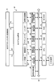
- FIG. 1 is a block diagram of a functional configuration of the holographic memory recording / reproducing apparatus according to the first embodiment.
- FIG. 2 is a schematic diagram showing the structure of the holographic memory recording medium 10.
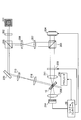
- FIG. 3 is a schematic diagram showing the configuration of the hologram optical system 20.
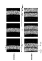
- FIG. 4A is an explanatory diagram illustrating a state of a reproduced image when the temperature at the time of information recording is the same as the temperature at the time of information reproduction.
- FIG. 4B is an explanatory diagram illustrating the state of a reproduced image when the temperature at the time of information recording is different from the temperature at the time of information reproduction.
- FIG. 5 is an explanatory diagram showing changes in the reproduced image when the reproduction angle is changed during information reproduction.
- FIG. 4A is an explanatory diagram illustrating a state of a reproduced image when the temperature at the time of information recording is the same as the temperature at the time of information reproduction.
- FIG. 4B is an explanatory diagram illustrating the state of
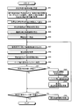
- FIG. 6 is a flowchart showing a procedure of information reproduction processing according to the first embodiment.
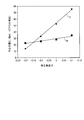
- FIG. 7 is a graph showing the relationship between the center position C of the partial image, the spread width W of the partial image, and the reproduction angle ⁇ .
- FIG. 8 is a time chart showing the operation of continuously playing back playback images at the optimal playback angle interval ⁇ s.
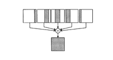
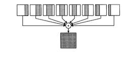
- FIG. 9A is an explanatory diagram illustrating a combined state when the reproduction angle is changed at the optimum reproduction angle interval ⁇ s .
- FIG. 9-2 is an explanatory diagram showing a combined state when the reproduction angle interval is smaller than the optimum angle.
- FIG. 9C is an explanatory diagram showing a combined state when the reproduction angle interval is larger than the optimum angle.
- FIG. 9A is an explanatory diagram illustrating a combined state when the reproduction angle is changed at the optimum reproduction angle interval ⁇ s .
- FIG. 9-2 is an explanatory diagram showing a combined state when the reproduction angle interval is smaller than the optimum
- FIG. 10 is an explanatory diagram showing a state in which a reproduced image obtained by changing the reproduction angle by a minute angle is divided into a plurality of regions.
- FIG. 11 is a flowchart illustrating a procedure of information reproduction processing according to the second embodiment.
- FIG. 12 is a flowchart illustrating a procedure of information reproduction processing according to the third embodiment.
- FIG. 1 is a block diagram of a functional configuration of the holographic memory recording / reproducing apparatus according to the first embodiment.
- the holographic memory recording / reproducing apparatus records interference fringes of information light and reference light on the holographic memory recording medium 10.
- the holographic memory recording / reproducing apparatus reproduces information recorded by irradiating the holographic memory recording medium 10 with reference light.
- the holographic memory recording / reproducing apparatus of the present embodiment mainly includes a hologram optical system 20 and a system controller 50 as shown in FIG.
- the hologram optical system 20 includes a laser light source 201, an image sensor 214, an actuator 230, a shutter 208, a spatial light modulator 204, and other optical components (not shown). Details of the hologram optical system 20 will be described later.
- the system controller 50 includes a signal processing circuit 45, a laser control circuit 40, an image sensor control circuit 41, a reproduction angle control circuit 42, a shutter control circuit 43, and a spatial light modulator control circuit. 44, an interface circuit (IF) 35 serving as an interface with the host device 36, a central processing unit (CPU) 31, a RAM (Random Access Memory) 32, and a ROM (Read Only Memory) 33. And a non-volatile random access memory (NV-RAM) 34 which is a nonvolatile memory.
- IF interface circuit
- CPU central processing unit
- RAM Random Access Memory
- ROM Read Only Memory
- NV-RAM non-volatile random access memory
- the laser control circuit 40 has appropriate reproduction laser power and recording laser power set based on a command from the CPU 31 when information is recorded on the holographic memory recording medium 10 or information is reproduced from the holographic memory recording medium 10.
- the laser light source 201 is controlled so as to be obtained as follows.
- the spatial light modulator control circuit 44 displays image data on the spatial light modulator 204 based on the recording data supplied from the host device 36 via the interface circuit 35 during information recording.
- the shutter control circuit 43 controls the opening and closing of the shutter 208.
- the shutter is opened when information is recorded, and the shutter 208 is closed when information is reproduced, thereby blocking the irradiation of the information holographic memory recording medium 10. .
- the image sensor control circuit 41 sets preset parameters of the image sensor 214 for the image sensor 214 based on a command from the CPU 31 when reproducing information from the holographic memory recording medium 10. Further, the image sensor control circuit 41 issues an imaging start timing signal to the image sensor 214 based on a command from the CPU 31. Further, the image sensor control circuit 41 acquires image data (reproduced image) of a reproduced image received by the image sensor 214 and records the acquired reproduced image in the RAM 32.
- the reproduction angle control circuit 42 performs control to change the relative angle between the reference beam and the holographic memory recording medium 10 based on a command from the CPU 31 during information recording or information reproduction. Specifically, the reproduction angle control circuit 42 sends a drive command to the actuator 230 when reproducing information from the holographic memory recording medium 10 so that the actuator 230 records the holographic memory for each predetermined reproduction angle. The medium 10 is driven, and thereby the relative angle between the reference light and the holographic memory recording medium 10 is changed.
- the signal processing circuit 45 performs various signal processing on the image data stored in the RAM 32.
- the CPU 31 controls the overall operation of the holographic memory recording / reproducing device in accordance with an operation command provided from the host device 36 through the interface circuit (IF) 35.
- the CPU 31 uses the RAM 32 as a work area, appropriately refers to the parameters for each device recorded in the NV-RAM 34, and executes the control program recorded in the ROM 32 (executes the optical information reproducing method of the present embodiment).
- a predetermined operation is performed in accordance with a program including
- FIG. 2 is a schematic diagram showing the structure of the holographic memory recording medium 10.
- the holographic memory recording medium 10 according to the present embodiment is a transmissive recording medium, and is sandwiched between two opposing substrates 12a and 12b and two substrates 12a and 12b as shown in FIG. And a hologram recording layer 13 laminated on the substrate 12b.
- the substrates 12a and 12b are formed of a light transmissive material such as glass, polycarbonate, or acrylic resin.
- the materials of the substrates 12a and 12b are not limited to these.
- the substrates 12a and 12b do not have to be transparent to laser light of all wavelengths, and are materials having transparency to the wavelength of laser light to be used. It only has to be formed.
- the hologram recording layer 13 is formed from a hologram recording material.
- the hologram recording material is a material in which a hologram is formed by causing information light of laser light and reference light to interfere with each other.
- the hologram recording material is generally formed of a radical polymerization type material called a photopolymer, and includes a radical polymerizable compound, a photo radical polymerization initiator, a matrix material, and the like.
- the hologram recording material is not limited to these materials, and any material may be used as long as the hologram recording material is available.
- FIG. 3 is a schematic diagram showing the configuration of the hologram optical system 20.
- a two-beam optical system which is a system in which the information light and the reference light are incident on the holographic memory recording medium 10 so as to be overlapped on the hologram recording layer 13 through separate objective lenses or the like, is adopted. Yes.
- FIG. 3 some optical components are not shown in order to avoid complexity.
- the laser light source 201 is a light source that emits laser light for recording and reproduction.
- the laser light source 210 generally uses a combination of a green or blue-violet semiconductor laser and an external resonator (not shown) for stabilizing the wavelength.
- the laser light source 201 may be configured to emit other wavelengths or laser light such as a so-called DFB laser, SHG laser, solid-state laser, or gas laser.
- the laser light emitted from the laser light source 201 passes through the quarter-wave plate 202 and is split into two light beams by the polarization beam splitter 203.
- the first light beam reflected by the polarization beam splitter 203 is adjusted by the collimator lenses 206 and 207 and then reflected by the polarization beam splitter 205 again.
- the first light beam reflected by the polarization beam splitter 205 enters the spatial light modulator 204.
- image data is displayed by the spatial light modulator control circuit 44, and the first light flux is modulated by the image data.
- the spatial light modulator 204 a liquid crystal element, a digital micromirror device, or the like can be used.
- the first light beam becomes convergent light by the condensing lens 211 and is condensed near the holographic memory recording medium 10 as information light.
- the shutter 208 is opened by the shutter control circuit 43 and does not block the first light flux as the information light.
- the second light beam transmitted through the polarization beam splitter 203 is reflected by the mirror 220, and the diameter is adjusted by the lenses 215 and 216. Thereafter, the second light beam enters the holographic memory recording medium 10 as reference light.
- hologram recording on the hologram recording layer 13 is performed as follows. First, interference fringes are formed by superimposing information light and reference light in the hologram recording layer 13. At this time, the photopolymerization initiator in the photopolymer absorbs and activates photons, and activates and accelerates the polymerization of the monomer in the interference fringe bright part. When the polymerization of the monomer proceeds and the monomer present in the bright part of the interference fringe is consumed, the monomer is moved and supplied from the dark part of the interference fringe to the bright part, resulting in a density difference between the bright part and the dark part of the interference fringe pattern. Thereby, refractive index modulation corresponding to the intensity distribution of the interference fringe pattern is formed, and hologram recording is performed.
- the shutter control circuit 43 closes the shutter 208 to block the information light, and only the reference light is incident on the holographic memory recording medium 10, so that the holographic memory recording medium 10 is received by the image sensor 214 as a reproduced image.
- a two-dimensional image sensor such as a CCD or a CMOS can be used for the image sensor 214.
- the present invention is not limited to this, and a one-dimensional linear image sensor may be used as the imaging element 214 by scanning, or an imaging tube may be used.
- optical path lengths of the information light and the reference light to the holographic memory recording medium 10 are preferably the same, but the optical path lengths are different as long as the so-called coherent length of the laser light source 201 is acceptable. It may be.
- a dichroic mirror is installed between the holographic memory recording medium 10 and the image sensor 214, or a polarization beam splitter or the like is installed between the holographic memory recording medium 10 and the image sensor 214. Also good. Alternatively, the image sensor 214 may be configured not to detect the wavelength of unnecessary light.
- the reproduction angle at the time of information reproduction by the holographic memory recording / reproducing apparatus will be described.
- the relative angle between the reference beam and the holographic memory recording medium 10 when reproducing information from the holographic memory recording medium 10 is referred to as a reproduction angle.
- FIGS. 4-1 and 4-2 are diagrams showing differences due to temperature differences between information recording and information reproduction of reproduced images.
- Fig. 4-1 shows the state of a reproduced image when the temperature at the time of information recording is the same as the temperature at the time of information reproduction
- Fig. 4-2 shows the reproduction when the temperature at the time of information recording is different from the temperature at the time of information reproduction. The state of the image is shown.
- the image data of information recorded at an angle ⁇ 1 with a relative angle between the reference light and the holographic memory recording medium 10 is usually the reference light when there is no difference between the temperature during information recording and the temperature during information reproduction.
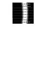
- FIG. 5 is an explanatory diagram showing changes in the reproduced image when the reproduction angle is changed during information reproduction.
- the upper diagram in FIG. 5 shows changes in the reproduced image when the reproduction angle ⁇ y is changed by a minute angle in the vicinity of ⁇ 1 when reproducing information recorded on only one page in the holographic memory recording medium 10. Show. Thus, even if the reproduction angle ⁇ y is changed, only a partial image is moved, and one good image cannot be obtained.
- the reproduced image is a good image at each recording angle step ⁇ y. Obtained as data.
- the temperature at the time of information reproduction changes from the temperature at the time of information recording, a part of the reproduced image is partially obtained as in the case of recording an image of one page. As shown in the figure, the partial image of the page one page before and the partial image of the page one page behind may appear at the same time.
- the reproduction angle interval ⁇ s is an angle step for changing a reproduction angle that is a relative angle between the reference light and the holographic memory recording medium 10 during information reproduction.
- the reproduction angle interval ⁇ s Is changed to obtain a plurality of partial images of the reproduced image.
- FIG. 6 is a flowchart showing a procedure of information reproduction processing according to the first embodiment. This information reproduction process is realized by the reproduction angle control circuit 42 and the CPU 31 executing the information reproduction program stored in the ROM 33.
- the reproduction angle control circuit 42 issues a drive command to the actuator 230, drives the holographic memory recording medium 10, and sets a reproduction angle, which is a relative angle between the reference light and the holographic memory recording medium 10, to a predetermined reference angle.
- ⁇ 0 is set (step S11).
- the predetermined reference angle is an angle at which a part of the reproduced image can be reproduced, it does not have to coincide with the angle when the page to be reproduced is recorded, and the reproduced image cannot be confirmed at that angle.
- the playback angle may be moved as appropriate until the playback image can be confirmed.
- the CPU 31 acquires the change amount of the width as a value related to the change amount and the area of the partial image in the reproduced image (step S12). Specifically, the following processing is performed.
- reproduction angle set to the reference angle ⁇ 0 reference light is emitted from the laser light source 201 and a reproduction image is acquired from the image sensor 214.
- the reproduction angle control circuit 42 performs a drive command to the actuator 230 drives the holographic-memory recording medium 10 is irradiated with reference light to change the reproduction angle from the reference angle theta 0 by a small angle theta d
- a reproduced image is acquired from the image sensor 214.
- the CPU 31 obtains the movement direction of the reproduction image from the two reproduction images acquired in this way, obtains the change in the luminance distribution of one or a plurality of pixel columns in the direction parallel to the movement direction, and obtains the reference angle ⁇ 0.
- the center position C 0 of the luminance distribution, the spread width W 0 of the brightness distribution, the center position C ′ 0 of the brightness distribution at the angle ⁇ 0 + ⁇ d , and the spread width W ′ 0 of the brightness distribution are obtained. That is, the difference C 0 -C ′ 0 in the center position of the luminance distribution is the amount of change in the position of the partial image, and the difference W 0 -W ′ 0 in the width of the luminance distribution is the amount of change in the value related to the area of the partial image.
- an angle at which a luminance peak passes between two predetermined points A and B on the image sensor 214 may be used as the minute angle ⁇ d .
- C 0 A
- C ′ 0 B
- the spread of the luminance distribution when passing through the point A is W
- the spread of the luminance distribution when passing through the point B is W ′.
- the CPU 31 represents the center position and spread width of the partial image as an approximate function of the reproduction angle (step S13).
- FIG. 7 is a graph showing the relationship between the center position C of the partial image, the spread width W of the partial image, and the reproduction angle ⁇ .
- the center position C of the partial image and the spread width W of the partial image can be approximated by a linear function of the reproduction angle ⁇ .
- the relationship between the center position C of the partial image and the spread width W of the partial image and the reproduction angle ⁇ may be approximated by a higher order function in addition to the linear function.
- the processing speed is improved and the mounting becomes simple.
- step S13 the CPU 31 changes the center position change amount (C 0 ⁇ C ′ 0 ), the spread width change amount (W 0 ⁇ W ′ 0 ), the minute amount obtained in step S12. using the angle ⁇ d (2) D, the E is calculated from the equation, the calculated D, with E (1) by obtaining the approximation function expressions of the partial image center position as spreading width playing angle Expressed as an approximate function.
- the reproduction angle range is a reproduction angle range in which a reproduction image can be acquired when performing a reproduction operation, and is a range indicated by an end angle from a start angle.
- the reproduction angle ⁇ min at which one page edge can be reproduced is calculated by first calculating ⁇ 1 obtained from equation (3-1) as ⁇ 1, ⁇ obtained from equation (3-2) as ⁇ 2 , and ⁇ 1 , It is calculated from equation (4) using ⁇ 2 . This ⁇ min is set as the start angle of the reproduction angle range.
- the CPU 31 calculates an optimum reproduction angle interval using the approximation function obtained by the equations (1) and (2) (step S15).
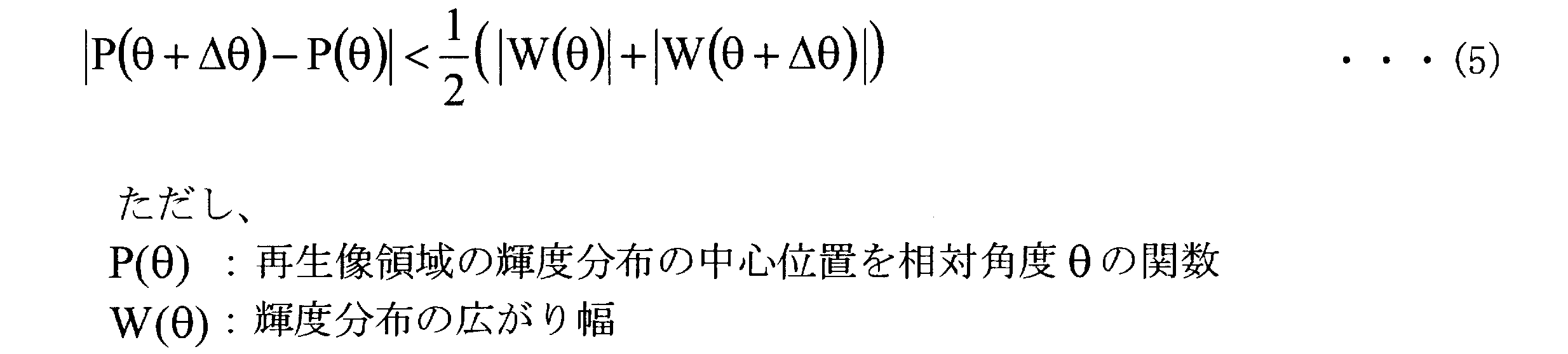
- the maximum ⁇ among ⁇ satisfying the expression (5) is set as the optimum reproduction angle interval ⁇ s .
- the optimum reproduction angle interval ⁇ s is obtained as a difference
- the optimum reproduction angle interval ⁇ s is expressed by the equation (7), and the CPU 31 calculates the optimum reproduction angle interval ⁇ s by the equation (7).
- the calibration process from steps S11 to S15 is always performed before the reproduction operation, but the present invention is not limited to this.
- the calibration processing from steps S11 to S15 is omitted, and the subsequent reproduction processing is executed. It can be constituted as follows.
- the reproduction angle interval ⁇ S is the angle multiplex recording interval at the time of recording.
- the reproduction process is performed according to the following procedure.
- the reproduction angle control circuit 42 issues a drive command to the actuator 230, drives the holographic memory recording medium 10, and obtains a reproduction angle that is a relative angle between the reference light and the holographic memory recording medium 10 in step S14.
- the image sensor control circuit 41 outputs an imaging start command to the image sensor 214 (step S17).
- the reference light is irradiated onto the holographic memory recording medium 10, and the image sensor 214 receives the reproduction light and outputs a reproduction image.
- the image sensor control circuit 41 acquires the reproduced image output from the image sensor 214 (step S18), and the CPU 31 extracts a partial image that is an area that is favorably reproduced from the acquired reproduced image and stores it in the RAM 32. (Step S19).
- a pixel whose luminance value is equal to or greater than a predetermined threshold is set as a partial image, and an off pixel (dark spot) in modulation data is set to be equal to or lower than the threshold
- a method is adopted in which an average luminance distribution is acquired using a low-pass filter, an area having a certain average luminance distribution that is equal to or greater than a predetermined threshold is determined, and only that area is extracted from a reproduced image as a partial image be able to.
- step S20 determines whether or not the number of extracted partial images has reached a predetermined number of elements. If it has not reached (step S20: No), the CPU 31 determines the predetermined number of pages to be restored. It is determined whether or not it has been reached (step S21).
- step S21 If the predetermined number of pages to be restored is not reached in step S21 (step S21: No), the reproduction angle control circuit 42 issues a drive command to the actuator 230 to drive the holographic memory recording medium 10.
- the reproduction angle which is the relative angle between the reference beam and the holographic memory recording medium 10, is moved by the reproduction angle interval ⁇ s obtained in step S15 (step S24), and the reproduction image acquisition from step S17 to S21, partial image Repeat the extraction process.
- step S20 when the number of extracted partial images has reached the predetermined number of elements (step S20: Yes), the CPU 31 outputs a compositing process start command (step S22). A plurality of partial images extracted thereby are combined to generate one reproduced image.
- a plurality of extracted partial images are stored in the RAM 31, and the synthesis process is performed when the number of extracted partial images reaches a predetermined number of elements.
- the timing to perform is not limited to this.
- a composition process may be performed each time a partial image is extracted from a reproduced image.
- the CPU 31 calculates and updates the optimum reproduction angle interval (step S23).
- the calculation of the optimum reproduction angle interval is performed in the same manner as the processing from steps S11 to S15 described above.
- the optimum reproduction angle interval is updated, so that the stage moving time or the reproduction image acquisition time by the actuator 230 is obtained.
- the update process is performed during this period, and it is possible to prevent the reproduction processing time, that is, the reproduction transfer rate from being affected.
- step S21 when the predetermined number of pages to be restored is reached (step S21: Yes), the process is terminated.
- FIG. 8 is a time chart showing the operation of continuously playing back playback images at the optimal playback angle interval ⁇ s.
- the vertical axis indicates the passage of time, and the horizontal axis indicates the reproduction angle.
- the arrows schematically show how the angle changes.
- FIGS. 9A to 9C are schematic diagrams for explaining a state in which a plurality of partial images acquired while changing the reproduction angle by the reproduction angle interval are combined.
- FIG. 9A shows a combined state when the reproduction angle is changed at the optimum reproduction angle interval ⁇ s .
- FIG. 9-2 shows a state where the reproduction angle interval is smaller than the optimum angle, and
- FIG. 9-3 shows a state where the reproduction angle interval is larger than the optimum angle.
- the reproduction angle interval is smaller than the optimum angle
- the acquired partial images include portions that overlap each other, so that unnecessary time is consumed more than necessary to acquire the partial images.
- the reproduction angle interval is larger than the optimum angle, the synthesized image is too coarse to restore one reproduced image.
- an optimum reproduction angle interval is calculated using an approximate function, and then the reproduction image is changed while changing the reproduction angle by the optimum reproduction angle interval. Therefore, it is possible to appropriately extract partial images from reproduced images without overlapping and without being too coarse. For this reason, in this embodiment, it is possible to accurately restore a single reproduced image without consuming unnecessary time, and to obtain a high-quality reproduced image while suppressing a decrease in transfer rate. Can do.
- a reproduction image obtained by changing the reproduction angle by a minute angle is divided into a plurality of regions, an approximation function is obtained for each region, and a reproduction angle interval is obtained.
- the reproduction angle interval is set to a proper value.
- the functional configuration of the holographic memory recording / reproducing device of this embodiment and the hologram optical system 20 are the same as those of the first embodiment.
- FIG. 10 is an explanatory diagram showing a state in which a reproduced image obtained by changing the reproduction angle by a minute angle is divided into a plurality of regions.
- a reproduction image obtained by changing the reproduction angle by a minute angle by the CPU 31 is an area in a direction orthogonal to the major axis of the partial image.
- FIG. 11 is a flowchart showing a procedure of information reproduction processing according to the second embodiment.
- the reproduction angle is set to the reference angle (step S31).
- a reproduction image is acquired by changing the reproduction angle by a minute angle, the acquired reproduction image is divided into the above-described areas, and the center position of each partial image and the amount of change in the spread width are changed in the same manner as in the first embodiment. (Step S32).
- step S33 an approximate function having the center position and the spread width as a function of the reproduction angle is obtained by the same method as in the first embodiment (step S33), and the start angle of the reproduction angle range is calculated for each region (step S33). Step S34). Next, an angle that is farthest from the reference angle is determined as a start angle from the start angles for each region (step S35).
- the CPU 31 obtains the optimum reproduction angle interval ⁇ sn for each region by the same method as in the first embodiment (step S36). Then, the CPU 31 determines the optimum reproduction angle interval ⁇ s that is the minimum angle from the reproduction angle intervals ⁇ sn obtained for each region (step S37). Then, the reproduction angle is moved to the start angle obtained in step S35 (step S38). Subsequent reproduction processing (steps S39 to S46) is performed in the same manner as in the first embodiment.
- a reproduction image obtained by changing the reproduction angle by a minute angle is divided into a plurality of areas, an approximation function is obtained for each area, and a start angle and a reproduction angle interval are obtained. Since the optimum one is determined, the reproduced image can be restored with higher accuracy, and a high-quality reproduced image can be obtained while suppressing a decrease in the transfer rate.
- the functional configuration of the holographic memory recording / reproducing device of this embodiment and the hologram optical system 20 are the same as those of the first embodiment.
- FIG. 12 is a flowchart showing a procedure of information reproduction processing according to the third embodiment.
- the reproduction angle is set to the reference angle (step S51).
- the reproduction angle is changed by a minute angle to obtain a reproduction image, an arbitrary partial image appearing in the acquired reproduction image is selected, and the change amount of the center position and the spread width of the selected partial image Is obtained by the same method as in the first embodiment (step S52).
- step S53 an approximate function having the center position and the spread width as a function of the reproduction angle is obtained (step S53), and the start angle of the reproduction angle range is calculated (step S54).
- the CPU 31 obtains the optimum reproduction angle interval ⁇ s by the same method as in the first embodiment (step S55), and moves the reproduction angle to the start angle obtained in step S54 (step S56).
- the image sensor control circuit 41 outputs an imaging start command to the image sensor 214 (step S57).
- the reference light is irradiated onto the holographic memory recording medium 10, and the image sensor 214 receives the reproduction light and outputs a reproduction image.
- the image sensor control circuit 41 acquires the reproduced image output from the image sensor 214 (step S58), and the CPU 31 applies a partial image that is an area that is favorably reproduced from the acquired reproduced image, as in the first embodiment. Are extracted based on the luminance value and stored in the RAM 32 (step S59).
- step S60 since partial images of a plurality of pages appear simultaneously in the reproduced image, the partial images that are well reproduced are classified by each page, and the partial images are extracted from the page. Each time it is stored in a different buffer on the RAM 32 (step S60).
- step S61 determines whether or not the number of extracted partial images has reached a predetermined number of elements. If it has not reached (step S61: No), the CPU 31 sets the predetermined number of pages to be restored. It is determined whether or not it has been reached (step S62).
- step S62 If the predetermined number of pages to be restored has not been reached in step S62 (step S62: No), the reproduction angle control circuit 42 issues a drive command to the actuator 230 to drive the holographic memory recording medium 10. Then, the reproduction angle, which is the relative angle between the reference beam and the holographic memory recording medium 10, is moved by the reproduction angle interval ⁇ s obtained in step S55 (step S66), and the reproduction image acquisition from step S57 to S62, partial image Repeat the extraction process.
- step S61 when the number of extracted partial images has reached the predetermined number of elements (step S61: Yes), the CPU 31 outputs a compositing process start command (step S63). Thus, a plurality of partial images extracted for each page and stored in the buffer are combined for each page, and a reproduction image for each page is generated (step S64).
- the CPU 31 calculates and updates the optimum reproduction angle interval (step S64).
- the calculation of the optimum reproduction angle interval is performed in the same manner as the processing from steps S51 to S55 described above.
- step S62 when the predetermined number of pages to be restored is reached (step S62: Yes), the process is terminated.
- an arbitrary partial image appearing in the reproduction image is selected, the amount of change in the center position and the amount of change in the spread width are calculated, and the optimum reproduction angle interval is calculated using the approximation function. Then, while changing the playback angle at the calculated playback angle interval, a plurality of partial images appearing in the playback image are extracted and synthesized page by page, so that information is multiplexed and recorded on the holographic memory recording medium 10 Even in such a case, it is possible to accurately restore the reproduced image for each page without consuming unnecessary time, and it is possible to obtain a high-quality reproduced image while suppressing a decrease in the transfer rate.
- the present invention is not limited to the above-described embodiment as it is, and can be embodied by modifying the constituent elements without departing from the scope of the invention in the implementation stage.
- various inventions can be formed by appropriately combining a plurality of constituent elements disclosed in the above embodiments. For example, some components may be deleted from all the components shown in the embodiment. Furthermore, constituent elements over different embodiments may be appropriately combined.
- holographic memory recording medium 10 hologram optical system 50 system controller 31 CPU 32 RAM 33 ROM 34 NV-RAM 35 Interface circuit (IF) 36 Host Device 40 Laser Control Circuit 41 Image Sensor Control Circuit 42 Playback Angle Control Circuit 43 Shutter Control Circuit 44 Spatial Light Modulator Control Circuit 45 Signal Processing Circuit 201 Laser Light Source 214 Image Sensor 230 Actuator 208 Shutter 204 Spatial Light Modulator
Landscapes
- Holo Graphy (AREA)
- Optical Recording Or Reproduction (AREA)
Abstract
再生角度制御回路42は、情報再生時における参照光と光情報記録媒体との相対角度である再生角度を微小角度だけ変化させながら参照光を照射し、再生光による再生画像における部分画像の位置の変化量である第1変化量および部分画像の面積に関する値の変化量である第2変化量を求める。そして、第1変化量と第2変化量とに基づいて、位置および面積に関する値と再生角度との関係を示す近似関数を求め、近似関数に基づいて、再生角度間隔を算出する。再生角度制御回路42は、再生角度を再生角度間隔ごとに変化させて参照光を照射し、撮像素子214は、再生光から再生画像を取得し、取得した再生画像のそれぞれの部分画像から、情報記録層に記録された情報の一ページの再生画像を合成する。
Description
本発明は、光情報再生方法および装置に関する。
CD(Compact Disc)やDVD(Digital Versatile Disc)、BD(Blu-ray Disc)等に代表される光情報記録媒体は、これまで主としてレーザ光の短波長化および対物レンズの開口数(NA)の増大により記録密度の増加に対応してきた。しかしながらそのいずれもが技術的な理由などにより限界に近づいているといわれており、その他の手段・方式による記録密度の増大が要望されている。
種々の提案の中で、近年、ホログラフィを用いた体積記録型の高密度光記録(以下、「ホログラフィックメモリ記録媒体」という。)およびホログラフィックメモリの記録再生装置の開発が実用化に向けて行われている。ホログラフィックメモリの記録方式は、液晶素子やデジタル・マイクロミラー・デバイス等の空間変調器によってレーザ光を空間的に変調して情報を担持する情報光と、情報光と同一波長で一般的には情報光と同一光源から生成される参照光を、記録媒体中の同一個所に照射し、その際に情報光と参照光とによってできる光の干渉縞を記録媒体中に記録するものである。
そして、ホログラフィックメモリ記録媒体の再生の際には、参照光のみを照射することにより、記録時の情報光が再現され、記録時に変調した情報を取得することができる。DVDなどのように記録面上に記録マークを記録するいわゆる面記録方式に対して、ホログラフィックメモリ記録媒体は、情報記録層の厚み方向への記録が可能な体積記録方式であるため、DVDなどに比べて大きな記録密度を獲得できる。
また、DVDなどの場合、記録マークは一般にON/OFFのビットデータを表すが、ホログラフィックメモリ記録媒体の場合、情報光は、比較的大量の情報により一括して変調されて干渉縞として記録される。この一組の情報は、記録媒体に保持する情報光の変調パターンで、白黒のドットで構成された2次元バーコード状の記録再生の最小単位であり、ページデータという。
ホログラフィックメモリ記録媒体の記録密度を増大させる方法の一つに、多重記録方式がある。この多重記録方式は、ホログラフィックメモリ記録媒体の同一場所に複数のページデータを記録する方式であり、レーザ光の照射角度をずらす角度多重記録、レーザ光の照射位置をわずかにずらすシフト多重記録など種々の方式が考案されている。
いずれの場合でも、多重記録されたページデータを読み出すためには、記録時のレーザ光とホログラフィックメモリ記録媒体との相対位置や相対角度を、再生時に再現することで初めて所望のページデータを読み出すことができるという特徴を有している。
しかしながら、再生時の温度が記録時よりも上昇した場合、媒体の体積膨張等の影響により記録されている干渉縞と再生参照光の間のブラッグ条件が一部で満たされなくなり、画像データの一部の領域しか再生されず、他の部分は再生されないという問題がある。即ち記録時と再生時で温度変化が生じると、従来の再生手法では記録情報を再現することが不可能となり、このことは実用化に向けた大きな課題の一つとなっている。
このような問題を解決するために、従来、各種手法が提案されている。例えば、特許文献1には、参照光の角度を複数角度変化させて一部だけ欠陥のない良好な再生画像を複数枚取得し、これらの良好な部分を画像合成により繋ぎあわせることで、温度変化が生じてもムラや欠けのない良好な画像を取得する技術が開示されている。また、特許文献2には、特許文献1の技術を前提として、さらに参照光の照射スポット位置を変化させることにより、良好な画像を取得する技術が開示されている。
しかしながら、特許文献1および2の技術では、複数の画像要素を取得する際の角度間隔の大小次第で、合成した際に一枚の再生画像を復元するための要素が不足する。このため、画像合成による再生が不可能となる場合や、必要以上の枚数の画像要素が取得されることにより、再生に要する時間が増大し、要素データを記憶しておくためのメモリを大量に消費する場合がある。この結果、再生信号の信頼性が劣化したり、転送レートの低下を招くという問題がある。
本発明は、上記に鑑みてなされたものであって、温度変化等により光情報記録媒体の体積変化に伴う画像劣化が生じた場合においても、転送レートの低下を抑制しつつ、高品位の再生画像を得ることができる光情報再生方法および装置を提供することを目的とする。
上述した課題を解決し、目的を達成するために、本発明にかかる光情報再生方法は、駆動部により、情報光と参照光との干渉によって生じる干渉縞によって情報をホログラムとして記録可能な情報記録層を有する光情報記録媒体または光学機構を駆動させて、情報再生時における前記参照光と前記光情報記録媒体との相対角度である再生角度を所定の微小角度だけ変化させながら前記参照光を照射し、前記情報記録層から出射される前記情報の再生光による再生画像における所定部分である部分画像の位置の変化量である第1変化量および前記部分画像の面積に関する値の変化量である第2変化量を求める第1算出ステップと、前記第1変化量と前記第2変化量とに基づいて、前記位置および前記面積に関する値と前記再生角度との関係を示す近似関数を求める第2算出ステップと、前記近似関数に基づいて、情報記録時における前記参照光と前記光情報記録媒体との相対角度よりも小さい角度である再生角度間隔を算出する第3算出ステップと、前記駆動部により前記光情報記録媒体または前記光学機構を駆動させて前記再生角度を前記再生角度間隔ごとに変化させて前記参照光を照射する制御ステップと、前記再生角度間隔ごとの前記再生光からの再生画像を取得し、取得した再生画像のそれぞれの前記部分画像から、前記情報記録層に記録された情報の一ページの再生画像を合成する合成ステップと、を含むことを特徴とする。
また、本発明にかかる光情報再生装置は、情報光と参照光との干渉によって生じる干渉縞によって情報をホログラムとして記録可能な情報記録層を有する光情報記録媒体に、前記参照光を導入する光学機構と、前記光情報記録媒体または前記光学機構を駆動する駆動部と、前記情報記録層から出射される前記情報の再生光を受光する受光部と、前記駆動部により前記光情報記録媒体または前記光学機構を駆動させて、情報再生時における前記参照光と前記光情報記録媒体との相対角度である再生角度を所定の微小角度だけ変化させながら前記参照光を照射し、前記再生光による再生画像における所定部分である部分画像の位置の変化量である第1変化量および前記部分画像の面積に関する値の変化量である第2変化量を求める第1算出部と、前記第1変化量と前記第2変化量とに基づいて、前記位置および前記面積に関する値と前記再生角度との関係を示す近似関数を求める第2算出部と、前記近似関数に基づいて、情報記録時における前記参照光と前記光情報記録媒体との相対角度よりも小さい角度である再生角度間隔を算出する第3算出部と、前記駆動部により前記光情報記録媒体または前記光学機構を駆動させて前記再生角度を前記再生角度間隔ごとに変化させて前記参照光を照射する制御部と、前記再生角度間隔ごとの前記再生光からの再生画像を取得し、取得した再生画像のそれぞれの前記部分画像から、前記情報記録層に記録された情報の一ページの再生画像を合成する合成部と、を備えたことを特徴とする。
本発明によれば、温度変化等により光情報記録媒体の体積変化に伴う画像劣化が生じた場合においても、転送レートの低下を抑制しつつ、高品位の再生画像を得ることができるという効果を奏する。
以下に添付図面を参照して、この発明にかかる光情報再生装置および方法の最良な実施の形態を詳細に説明する。
(実施の形態1)
図1は、実施の形態1にかかるホログラフィックメモリ記録再生装置の機能的構成を示すブロック図である。ホログラフィックメモリ記録再生装置は、ホログラフィックメモリ記録媒体10に情報光と参照光の干渉縞を記録する。また、ホログラフィックメモリ記録再生装置は、ホログラフィックメモリ記録媒体10に参照光を照射することによって記録されている情報を再生する。
図1は、実施の形態1にかかるホログラフィックメモリ記録再生装置の機能的構成を示すブロック図である。ホログラフィックメモリ記録再生装置は、ホログラフィックメモリ記録媒体10に情報光と参照光の干渉縞を記録する。また、ホログラフィックメモリ記録再生装置は、ホログラフィックメモリ記録媒体10に参照光を照射することによって記録されている情報を再生する。
本実施の形態のホログラフィックメモリ記録再生装置は、図1に示すように、ホログラム光学系20とシステムコントローラ50とを主に備えている。
ホログラム光学系20は、図1に示すように、レーザ光源201と、撮像素子214と、アクチュエータ230と、シャッター208と、空間光変調器204と、その他光学部品(不図示)を備えている。ホログラム光学系20の詳細については後述する。
システムコントローラ50は、図1に示すように、信号処理回路45と、レーザ制御回路40と、撮像素子制御回路41と、再生角度制御回路42と、シャッター制御回路43と、空間光変調器制御回路44と、ホスト装置36とのインタフェースとなるインタフェース回路(IF)35と、主演算処理ブロックであるCPU(Central Processing Unit)31と、RAM(Random Access Memory)32と、ROM(Read Only Memory)33と、不揮発性メモリであるNV-RAM(Non-Volatile Random Access Memory)34とを備えている。
レーザ制御回路40は、ホログラフィックメモリ記録媒体10への情報記録時あるいはホログラフィックメモリ記録媒体10からの情報再生時に、CPU31の指令に基づいて設定された再生時レーザパワー、記録時レーザパワーが適切に得られるようにレーザ光源201を制御する。
空間光変調器制御回路44は、情報記録時に、ホスト装置36からインタフェース回路35を介して供給される記録データに基づいて、画像データを空間光変調器204に表示する。
シャッター制御回路43は、シャッター208の開閉を制御するものであり、情報記録時にシャッターを開状態にし、情報再生時にシャッター208を閉状態にして、情報のホログラフィックメモリ記録媒体10の照射を遮断する。
撮像素子制御回路41は、ホログラフィックメモリ記録媒体10からの情報再生時に、CPU31からの指令に基づいて、予め設定された撮像素子214のパラメータを撮像素子214に対して設定する。また、撮像素子制御回路41は、CPU31からの指令に基づいて、撮像開始のタイミング信号を撮像素子214に対して発行する。さらに、撮像素子制御回路41は、撮像素子214で受光した再生像の画像データ(再生画像)を取得して、取得した再生画像をRAM32に記録する。
再生角度制御回路42は、情報記録時あるいは情報再生時に、参照光とホログラフィックメモリ記録媒体10の相対角度をCPU31からの指令に基づいて変化させる制御を行う。具体的には、再生角度制御回路42は、ホログラフィックメモリ記録媒体10からの情報の再生時に、アクチュエータ230に対して駆動指令を送出することよりアクチュエータ230が所定の再生角度ごとにホログラフィックメモリ記録媒体10を駆動して、これにより、参照光とホログラフィックメモリ記録媒体10の相対角度を変化させる。
信号処理回路45は、RAM32に保存された画像データに対する各種信号処理を行う。
図1に示すように、信号処理回路45、レーザ制御回路40、撮像素子制御回路41、再生角度制御回路42、シャッター制御回路43、空間光変調器制御回路44、IF35、CPU31、RAM32、ROM33、NV-RAM34は、すべて信号バス30に接続されており、この信号バス30を介してCPU31によって制御される。CPU31は、インタフェース回路(IF)35通じてホスト装置36から提供される動作コマンドに従って、ホログラフィックメモリ記録再生装置の全体動作を制御する。また、CPU31は、RAM32を作業領域として使用し、NV-RAM34に記録された装置個体ごとのパラメータを適宜参照し、ROM32に記録されている制御プログラム(本実施の形態の光情報再生方法を実行するプログラムを含む)に従って所定の動作を行う。
次に、本実施の形態にかかるホログラフィックメモリ記録再生装置で記録再生の対象となるホログラフィックメモリ記録媒体10の詳細について説明する。
図2は、ホログラフィックメモリ記録媒体10の構造を示す模式図である。本実施の形態にかかるホログラフィックメモリ記録媒体10は、透過型の記録媒体であり、図2に示すように、対向する2つの基板12a,12bと、2つの基板12a、12bとの間に挟持されて基板12b上に積層されたホログラム記録層13とを含んでいる。
基板12a,12bは、ガラス、ポリカーボネート、アクリル樹脂等の光透過性を有する材質で形成される。ただし、基板12a,12bの材質は、これらに限定されるものではなく、例えば、全波長のレーザ光に対して透過性を有する必要はなく、使用するレーザ光の波長に対する透過性を有する材質で形成されていればよい。
ホログラム記録層13は、ホログラム記録材料から形成されている。ホログラム記録材料は、レーザ光の情報光と参照光とを干渉させてホログラムが形成される材料である。ホログラム記録材料としては、一般にはフォトポリマーと呼ばれるラジカル重合形の材質で形成され、ラジカル重合性化合物、光ラジカル重合開始剤、マトリックス材料等が含まれる。なお、ホログラム記録材料は、これらの材料に限定されるものではなく、ホログラム記録が可能な材料であれば、いずれの材料を用いても良い。
次に、本実施の形態にかかるホログラフィックメモリ記録再生装置の光学系について説明する。図3は、ホログラム光学系20の構成を示す模式図である。
本実施の形態では、情報光と参照光は、別々の対物レンズ等を経てホログラム記録層13において重なるようにホログラフィックメモリ記録媒体10に入射させる方式である二光束方式の光学系を採用している。なお、図3において、煩雑さを避けるために、一部の光学部品を省略して図示している。
レーザ光源201は、記録再生用のレーザ光を出射する光源である。レーザ光源210は、一般には緑色や青紫色の半導体レーザおよび波長を安定させるための外部共振器(不図示)を組み合わせて用いている。なお、レーザ光源201として、その他の波長や、いわゆるDFBレーザ、SHGレーザ、固体レーザ、気体レーザなどのレーザ光を出射するように構成してもよい。
レーザ光源201から出射されたレーザ光は、1/4波長板202を通過し、偏光ビームスプリッタ203によって2つの光束に分割される。2つの光束のうち偏光ビームスプリッタ203によって反射された第1の光束は、コリメータレンズ206,207により径の調整をされた後、再び偏光ビームスプリッタ205で反射される。そして、偏光ビームスプリッタ205で反射した第1の光束は、空間光変調器204に入射する。空間光変調器204には、空間光変調器制御回路44によって画像データが表示されており、第1の光束は、かかる画像データによって変調される。ここで、空間光変調器204としては、液晶素子やデジタル・マイクロミラー・デバイス等を用いることができる。
そして、この第1の光束は、集光レンズ211により収束光となり、情報光としてホログラフィックメモリ記録媒体10付近に集光する。なお、このときシャッター208は、シャッター制御回路43により開状態となっており、情報光としての第1の光束を遮断することはない。
一方、偏光ビームスプリッタ203によって分割された2つの光束のうち偏光ビームスプリッタ203を透過した第2の光束は、ミラー220で反射され、レンズ215,216により直径が調整される。その後、この第2の光束は、ホログラフィックメモリ記録媒体10に参照光として入射する。
このような光学系により、ホログラム記録層13へのホログラム記録は、次のように行われる。まず、情報光と参照光をホログラム記録層13中で重ね合わせて干渉縞を形成する。この時、フォトポリマー中の光重合開始剤がフォトンを吸収して活性化し、干渉縞明部のモノマーの重合を発動・促進させる。モノマーの重合が進行して干渉縞明部に存在するモノマーが消費されると、干渉縞暗部から明部にモノマーが移動供給され、結果、干渉縞パターンの明部と暗部に密度差が生じる。これにより、干渉縞パターンの強度分布に応じた屈折率変調が形成されホログラム記録が行われる。
ここで、ホログラフィックメモリ記録媒体10の再生時は、シャッター制御回路43によってシャッター208を閉状態として情報光を遮断し、参照光のみをホログラフィックメモリ記録媒体10に入射させ、ホログラフィックメモリ記録媒体10のから出射される再生光を再生像として撮像素子214により受光する。ここで、撮像素子214には、CCDやCMOSなどの2次元イメージセンサを用いることができる。ただし、これに限定されるものではなく、撮像素子214として1次元のリニアイメージセンサを走査して用いたり、撮像管を用いるように構成することもできる。
なお、情報光と参照光のホログラフィックメモリ記録媒体10にいたるまでの光路長は同一であることが好ましいが、レーザ光源201のいわゆるコヒーレント長で許容される範囲であれば、当該光路長は異なっていてもよい。
この他、ホログラフィックメモリ記録媒体10と撮像素子214との間にダイクロイックミラーを設置したり、ホログラフィックメモリ記録媒体10と撮像素子214との間に偏光ビームスプリッタ等を設置するように構成してもよい。あるいは、撮像素子214を不要光の波長を検出しない構成としてもよい。
次に、本実施の形態にかかるホログラフィックメモリ記録再生装置による情報再生時の再生角度について説明する。ここで、以降では、ホログラフィックメモリ記録媒体10からの情報再生時における参照光とホログラフィックメモリ記録媒体10との相対角度を再生角度という。
図4-1および図4-2は、再生画像の情報記録時と情報再生時の温度差による違いを示す図である。図4-1は、情報記録時の温度と情報再生時の温度が等しい場合の再生画像の状態を示し、図4-2は、情報記録時の温度と情報再生時の温度が異なる場合の再生画像の状態を示している。
参照光とホログラフィックメモリ記録媒体10の相対角度がある角度θ1で記録された情報の画像データは、通常、情報記録時の温度と情報再生時の温度に違いがない場合には、参照光とホログラフィックメモリ記録媒体10との相対角度、すなわち再生角度をθy=θ1で再生した場合、情報記録時に形成された干渉縞と再生参照光の間のブラッグ条件が画像データ全面に渡ってほぼ完全に一致するため、図4-1に示すように、一枚の再生画像として得ることができる。
しかしながら、情報再生時の温度が情報記録時の温度から変化している場合には、再生角度θy=θ1で再生した場合でも、ホログラフィックメモリ記録媒体10の体積膨張等の影響により記録された干渉縞が変形する。これにより、情報記録時の参照光と情報再生時の参照光との間のブラッグ条件が一部で満たされなくなる。その結果、このように情報記録時と情報再生時との間に温度差が生じた場合において、再生時に取得した再生画像は、図4-2に示すように、記録した画像データの一部分のみにスポットライトが当たったような部分的な画像(以下、「部分画像」という。)が得られることになる。
図5は、情報再生時において再生角度を変化させた場合の再生画像の変化を示す説明図である。図5の上段の図は、ホログラフィクメモリ記録媒体10に1ページのみ記録された情報を再生する際に、再生角度θyをθ1近傍において微小角度だけ変化させた場合の再生画像の変化を示している。このように再生角度θyを変化させても部分画像が移動するだけで1枚の良好な画像が得られない。
ホログラフィックメモリ記録媒体10に情報が記録角度ステップΔθyで角度多重記録された場合において情報記録時の温度近傍の温度下で再生した場合、再生画像は、記録角度ステップΔθyごとに良好な画像データとして得られる。しかしながら、情報再生時の温度が情報記録時の温度から変化している場合には、1ページの画像が記録された場合と同様に、再生画像の一部分が部分的に得られ、図5の下段の図に示すように、1ページ前のページの部分画像と1ページ後ろのページの部分画像とが同時に現れてしまう場合がある。
本実施の形態にかかるホログラフィックメモリ記録媒体10の情報再生の処理では、情報再生の前にキャリブレーション処理を行って後述する近似関数により最適な再生角度間隔θsを求め、この最適な再生角度間隔で再生角度を変化させて再生画像の複数の部分画像を連続的に取得して合成することにより、情報記録時の温度と情報再生時の温度に差がある場合でも、正確に1ページの再生画像を得るようにしている。ここで、再生角度間隔θsは、情報再生時において、参照光とホログラフィックメモリ記録媒体10との相対角度である再生角度を変化させる角度ステップである、言い換えれば、この再生角度間隔で再生角度を変化させて再生画像の複数の部分画像を取得している。
以下、本実施の形態の情報再生の処理について説明する。図6は、実施の形態1の情報再生処理の手順を示すフローチャートである。この情報再生処理は、再生角度制御回路42と、CPU31がROM33に記憶された情報再生プログラムを実行することにより実現される。
まず、再生角度制御回路42は、アクチュエータ230に駆動指令を行い、ホログラフィックメモリ記録媒体10を駆動して、参照光とホログラフィックメモリ記録媒体10の相対角度である再生角度を、所定の基準角度θ0に設定する(ステップS11)。このときの所定の基準角度は、再生画像が一部でも再生できる角度であれば、再生対象のページを記録した際の角度に一致している必要はなく、その角度で再生画像を確認できなければ再生画像を確認できるまで再生角度を適宜移動させればよい。
次に、CPU31は、再生画像における部分画像の位置の変化量及び面積に関する値として幅の変化量を取得する(ステップS12)。具体的には、以下のような処理を行う。
再生角度を基準角度θ0に設定した状態でレーザ光源201から参照光を出射して、撮像素子214から再生画像を取得する。
次に、再生角度制御回路42は、アクチュエータ230に駆動指令を行い、ホログラフィックメモリ記録媒体10を駆動して、再生角度を基準角度θ0から微小角度θdだけ変化させて参照光を照射して、撮像素子214から再生画像を取得する。そして、CPU31は、このようにして取得した2つの再生画像から再生画像の移動方向を求め、この移動方向に平行な方向の一または複数の画素列の輝度分布の変化を求め、基準角度θ0における輝度分布の中心位置C0、輝度分布の広がり幅W0、角度θ0+θdにおける輝度分布の中心位置C’0、輝度分布の広がり幅W’0を求める。すなわち、輝度分布の中心位置の差分C0-C’0が部分画像の位置の変化量、輝度分布の幅の差分W0-W’0が部分画像の面積に関する値の変化量となる。
なお、撮像素子214上の所定の2点間A,B間を輝度のピークが通過する角度を微小角度θdとして用いてもよい。この場合は、C0=A、C’0=B、点Aを通過したときの輝度分布の広がりがW、点Bを通過したときの輝度分布の広がりがW’となる。
次に、CPU31は、部分画像の中心位置と広がり幅を再生角度の近似関数として表す(ステップS13)。
図7は、部分画像の中心位置C及び部分画像の広がり幅Wと再生角度θとの関係を示すグラフである。図7に示すように、部分画像の中心位置C及び部分画像の広がり幅Wは、再生角度θの概ね一次関数で近似できることが分かっている。なお、部分画像の中心位置C及び部分画像の広がり幅Wと再生角度θとの関係を一次関数で近似する他、高次の関数で近似してもよい。ただし、一次関数を用いて近似する場合には、処理速度を向上させ、かつ実装も簡便となる。
従って、部分画像としての輝度分布の中心位置の再生角度θの近似関数をC(θ)、輝度分布の広がり幅の再生角度θの近似関数をW(θ)とすると、C(θ)、W(θ)は基準角度θ0における中心位置C0、広がり幅W0、角度θ0+θdにおける中心位置C’0、広がり幅W’0を用い、以下の(1)式で表される。(1)式において、D、Eは(2)式で示される。


すなわち、ステップS13では、CPU31は、ステップS12で求めた部分画像(輝度分布)の中心位置の変化量(C0-C’0)、広がり幅の変化量(W0-W’0)、微小角度θdを用いて(2)式からD,Eを算出し、算出したD,Eを用いて(1)式の近似関数を求めることで、部分画像の中心位置と広がり幅を再生角度の近似関数として表している。
次に、CPU31は、このように求めた近似関数を用いて、再生動作の再生角度範囲の開始角度を求める(ステップS14)。再生角度範囲は、再生動作を行う場合に、再生画像を取得することが可能な再生角度の範囲であり、開始角度から終了角度で示される範囲となる。一方のページ端を再生できる再生角度θminは、まず、(3-1)式より得られるθをθ1、(3-2)式より得られるθをθ2として算出し、さらにθ1、θ2を用いて、(4)式から計算される。このθminを再生角度範囲の開始角度とする。


次に、CPU31は、(1)、(2)式で求めた近似関数を用いて、最適な再生角度間隔を算出する(ステップS15)。
本実施の形態では、(5)式を満たすΔθの中で最大のΔθを最適な再生角度間隔θsとしている。
より具体的に示すと、最適な再生角度間隔θsは、(6-1)式を満たすθ1と、(6-2)式を満たすθ2との差|θ1-θ2|として求める。

すなわち、最適な再生角度間隔θsは、(7)式で示されることになり、CPU31は、この(7)式により最適な再生角度間隔θsを算出する。

なお、本実施の形態では、ステップS11からS15までのキャリブレーション処理を再生動作の前に必ず行っているが、これに限定されるものではない。例えば、再生画像全体の輝度分布から、1ページの画像データが完全に再生されていると判断され場合には、ステップS11からS15までのキャリブレーション処理を省略して、以降の再生処理を実行するように構成することができる。この場合には、再生角度間隔θSは記録時の角度多重記録間隔となる。
以上のようにキャリブレーション処理が完了すると、以下の手順で再生処理を行う。まず、再生角度制御回路42はアクチュエータ230に駆動指令を行い、ホログラフィックメモリ記録媒体10を駆動して、参照光とホログラフィックメモリ記録媒体10の相対角度である再生角度を、ステップS14で求めた開始角度θminに移動する(ステップS16)。
そして、撮像素子制御回路41が撮像素子214に対して撮像開始命令を出力する(ステップS17)。これにより、参照光がホログラフィックメモリ記録媒体10に照射されて、撮像素子214はその再生光を受光して再生画像を出力する。
撮像素子制御回路41は、撮像素子214から出力された再生画像を取得し(ステップS18)、CPU31は、取得した再生画像から良好に再生されている領域である部分画像を抽出し、RAM32に保存する(ステップS19)。
ここで、良好に再生されている領域を判定する判定手法の一例としては、輝度値が所定の閾値以上の画素を部分画像とする他、変調データ中のオフピクセル(暗点)を閾値以下と誤認しないように、低域通過フィルターを用いて平均輝度分布を取得し、平均輝度分布のある所定の閾値以上の領域を決定し、その領域のみを部分画像として再生画像から抽出する手法を採用することができる。
そして、CPU31は、抽出した部分画像の数が所定の要素数に達したかを判断し(ステップS20)、到達していない場合には(ステップS20:No)、所定の復元すべきページ数に到達したか否かを判断する(ステップS21)。
そして、ステップS21で所定の復元すべきページ数に到達していない場合には(ステップS21:No)、再生角度制御回路42はアクチュエータ230に駆動指令を行い、ホログラフィックメモリ記録媒体10を駆動して参照光とホログラフィックメモリ記録媒体10の相対角度である再生角度を、ステップS15で求めた再生角度間隔θs分移動し(ステップS24)、ステップS17からS21までの再生画像の取得、部分画像の抽出の処理を繰り返す。
ステップS20において、抽出した部分画像の数が所定の要素数に到達している場合には(ステップS20:Yes)、CPU31は合成処理開始命令を出力する(ステップS22)。これより抽出された複数の部分画像が合成され一枚の再生画像が生成される。
ここで、本実施の形態では、抽出した複数の部分画像をRAM31に保存しておき、抽出した部分画像の数が所定の要素数に達した段階で合成処理を行っているが、合成処理を行うタイミングはこれに限定されるものではない。例えば、再生画像から部分画像を抽出するごとに合成処理を行うように構成してもよい。
合成処理が完了したら、CPU31は最適な再生角度間隔を算出して更新する(ステップS23)。最適な再生角度間隔の算出は、上記で説明したステップS11からS15までの処理と同様に行われる。このように、アクチュエータ230への駆動命令もしくは撮像素子215に対して撮像命令を出力した直後に、最適な再生角度間隔の更新を行うことで、アクチュエータ230によるステージの移動時間もしくは再生画像の取得時間中に更新処理を行うことになり、再生処理時間すなわち再生転送レートに影響を与えることを防止することができる。
ステップS21において、所定の復元すべきページ数に到達した場合(ステップS21:Yes)、処理を終了する。
図8は、最適な再生角度間隔θsで連続的に再生画像を再生する動作を示すタイムチャートである。図8において、縦軸が時間経過を示し、横軸が再生角度を示している。図8において、矢印は角度の変化する様子を模式的に示したものである。ページを再生するごとに再生角度間隔θsを更新することにより、再生中の温度変化にも追従した角度制御が可能となる。
図9-1~図9-3は、再生角度間隔ずつ再生角度を変化させながら取得した複数の部分画像を合成する状態を説明するための模式図である。図9-1は、最適な再生角度間隔θsで再生角度を変化させた場合の合成の状態を示している。図9―2は再生角度間隔が最適な角度より小さい場合の状態を示し、図9―3は再生角度間隔が最適な角度より大きい場合の状態を示している。
図9-2の例では、再生角度間隔が最適な角度より小さいため、取得された部分画像が互いに重複する部分を含み、このため部分画像の取得に必要以上の無駄な時間を消費することになる。図9-3の例では、再生角度間隔が最適な角度より大きいため、合成される画像が粗すぎて一枚の再生画像を復元することができない。
これに対し、図9-1に示す本実施の形態では、情報再生時に、近似関数を用いて最適な再生角度間隔を算出してから再生角度をこの最適な再生角度間隔ずつ変化させながら再生画像を取得しているので、再生画像から部分画像を重複なく、かつ粗すぎずに適切に抽出することができる。このため、本実施の形態では、無駄な時間の消費を行うことなく、一枚の再生画像を正確に復元することができ、転送レートの低下を抑制しつつ、高品位の再生画像を得ることができる。
(実施の形態2)
実施の形態2では、再生角度を微小角度変化させて取得した再生画像を複数の領域に分割し、領域ごとに近似関数を求めて再生角度間隔を求め、その中から最小の角度のものを最適な再生角度間隔とするものである。
実施の形態2では、再生角度を微小角度変化させて取得した再生画像を複数の領域に分割し、領域ごとに近似関数を求めて再生角度間隔を求め、その中から最小の角度のものを最適な再生角度間隔とするものである。
本実施の形態のホログラフィックメモリ記録再生装置の機能的構成およびホログラム光学系20については実施の形態1と同様である。
図10は、再生角度を微小角度変化させて取得した再生画像を複数の領域に分割した状態を示す説明図である。図10に示すように、本実施の形態のホログラフィックメモリ記録再生装置では、CPU31により、再生角度を微小角度変化させて取得した再生画像を、部分画像の長軸に対して直行する方向に領域を分割し、領域ごとに部分画像(輝度分布)の中心位置の関数Cn(θ)、部分画像(輝度分布)の関数Wn(θ)、及び再生角度間隔θsnを算出する(ここで、n=0,1,2・・・)。そして、算出した領域ごとの再生角度間隔θsnの中で最小の再生角度間隔θsnを最適な再生角度間隔θsと決定する。
図11は、実施の形態2の情報再生処理の手順を示すフローチャートである。まず、実施の形態1と同様に、再生角度を基準角度に設定する(ステップS31)。そして、再生角度を微小角度だけ変化させて再生画像を取得し、取得した再生画像を上記領域に区切り、領域ごとに部分画像の中心位置および広がり幅の変化量を実施の形態1と同様の手法で取得する(ステップS32)。
そして、領域ごとに、実施の形態1と同様の手法で、中心位置および広がり幅を再生角度の関数とした近似関数を求め(ステップS33)、領域ごとに再生角度範囲の開始角度を算出する(ステップS34)。次いで、領域ごとの開始角度の中から、基準角度と最も離れている角度を開始角度として決定する(ステップS35)。
次に、CPU31は、領域ごとに、実施の形態1と同様の手法で最適な再生角度間隔θsnを求める(ステップS36)。そして、CPU31は、領域ごとに求めた再生角度間隔θsnの中から、最小角度となるものを最適な再生角度間隔θsとして決定する(ステップS37)。そして、再生角度をステップS35で求めた開始角度に移動する(ステップS38)。これ以降の再生処理(ステップS39~S46)については実施の形態1と同様に行われる。
このように本実施の形態では、再生角度を微小角度変化させて取得した再生画像を複数の領域に分割し、領域ごとに近似関数を求めて開始角度および再生角度間隔を求め、それぞれの中から最適なものを決定しているので、より高精度に再生画像を復元することができ、転送レートの低下を抑制しつつ、高品位の再生画像を得ることができる。
(実施の形態3)
実施の形態3は、ホログラフィックメモリ記録媒体10に情報が多重記録されている場合のキャリブレーション処理を行うものである。
実施の形態3は、ホログラフィックメモリ記録媒体10に情報が多重記録されている場合のキャリブレーション処理を行うものである。
本実施の形態のホログラフィックメモリ記録再生装置の機能的構成およびホログラム光学系20については実施の形態1と同様である。
多重記録されている場合には、前述した図5の下段の図に示すように、再生画像の中に他のページの部分画像が現れる。本実施の形態では、このような場合に、いずれかの部分画像に選択して、その位置の変化量および広がり幅の変化量を算出し、近似関数を用いて最適な再生角度間隔を算出している。そして、算出した再生角度間隔で再生角度を変化させながら、再生画像を取得し、再生画像に現れている複数の部分画像を抽出してページごとに合成している。
図12は、実施の形態3の情報再生処理の手順を示すフローチャートである。まず、実施の形態1と同様に、再生角度を基準角度に設定する(ステップS51)。そして、再生角度を微小角度だけ変化させて再生画像を取得し、取得した再生画像に現れる複数の部分画像のうち任意の部分画像を選択し、選択した部分画像の中心位置および広がり幅の変化量を実施の形態1と同様の手法で取得する(ステップS52)。
そして、実施の形態1と同様の手法で、中心位置および広がり幅を再生角度の関数とした近似関数を求め(ステップS53)、再生角度範囲の開始角度を算出する(ステップS54)。
次に、CPU31は、実施の形態1と同様の手法で、最適な再生角度間隔θsを求め(ステップS55)、再生角度をステップS54で求めた開始角度に移動する(ステップS56)。
そして、撮像素子制御回路41が撮像素子214に対して撮像開始命令を出力する(ステップS57)。これにより、参照光がホログラフィックメモリ記録媒体10に照射されて、撮像素子214はその再生光を受光して再生画像を出力する。
撮像素子制御回路41は、撮像素子214から出力された再生画像を取得し(ステップS58)、CPU31は、取得した再生画像から良好に再生されている領域である部分画像を実施の形態1と同様に輝度値に基づいて抽出し、RAM32に保存する(ステップS59)。
そして、本実施の形態では、再生画像中に複数のページの部分画像が同時に現れているので、それぞれのページ毎に分類して、良好に再生されている部分画像を抽出し、部分画像をページごとにRAM32上の異なるバッファに保存する(ステップS60)。
そして、CPU31は、抽出した部分画像の数が所定の要素数に達したかを判断し(ステップS61)、到達していない場合には(ステップS61:No)、所定の復元すべきページ数に到達したか否かを判断する(ステップS62)。
そして、ステップS62で所定の復元すべきページ数に到達していない場合には(ステップS62:No)、再生角度制御回路42はアクチュエータ230に駆動指令を行い、ホログラフィックメモリ記録媒体10を駆動して参照光とホログラフィックメモリ記録媒体10の相対角度である再生角度を、ステップS55で求めた再生角度間隔θs分移動し(ステップS66)、ステップS57からS62までの再生画像の取得、部分画像の抽出の処理を繰り返す。
ステップS61において、抽出した部分画像の数が所定の要素数に到達している場合には(ステップS61:Yes)、CPU31は合成処理開始命令を出力する(ステップS63)。これより、ページごとに抽出されてバッファに保存された複数の部分画像がそれぞれページごとに合成されページごとの再生画像が生成される(ステップS64)。
合成処理が完了したら、CPU31は最適な再生角度間隔を算出して更新する(ステップS64)。最適な再生角度間隔の算出は、上記で説明したステップS51からS55までの処理と同様に行われる。
ステップS62において、所定の復元すべきページ数に到達した場合(ステップS62:Yes)、処理を終了する。
このように本実施の形態では、再生画像に現れる任意の部分画像に選択して、その中心位置の変化量および広がり幅の変化量を算出し、近似関数を用いて最適な再生角度間隔を算出し、算出した再生角度間隔で再生角度を変化させながら、再生画像に現れている複数の部分画像を抽出してページごとに合成しているので、情報がホログラフィックメモリ記録媒体10に多重記録されている場合においても、無駄な時間の消費を行うことなく、ページごとの再生画像を正確に復元することができ、転送レートの低下を抑制しつつ、高品位の再生画像を得ることができる。
なお、本発明は、上記実施の形態そのままに限定されるものではなく、実施段階ではその要旨を逸脱しない範囲で構成要素を変形して具体化することができる。また、上記実施の形態に開示されている複数の構成要素の適宜な組み合わせにより、種々の発明を形成することができる。例えば、実施の形態に示される全構成要素からいくつかの構成要素を削除してもよい。さらに、異なる実施の形態にわたる構成要素を適宜組み合わせても良い。
10 ホログラフィックメモリ記録媒体
20 ホログラム光学系
50 システムコントローラ
31 CPU
32 RAM
33 ROM
34 NV-RAM
35 インタフェース回路(IF)
36 ホスト装置
40 レーザ制御回路
41 撮像素子制御回路
42 再生角度制御回路
43 シャッター制御回路
44 空間光変調器制御回路
45 信号処理回路
201 レーザ光源
214 撮像素子
230 アクチュエータ
208 シャッター
204 空間光変調器
20 ホログラム光学系
50 システムコントローラ
31 CPU
32 RAM
33 ROM
34 NV-RAM
35 インタフェース回路(IF)
36 ホスト装置
40 レーザ制御回路
41 撮像素子制御回路
42 再生角度制御回路
43 シャッター制御回路
44 空間光変調器制御回路
45 信号処理回路
201 レーザ光源
214 撮像素子
230 アクチュエータ
208 シャッター
204 空間光変調器
Claims (10)
- 駆動部により、情報光と参照光との干渉によって生じる干渉縞によって情報をホログラムとして記録可能な情報記録層を有する光情報記録媒体または光学機構を駆動させて、情報再生時における前記参照光と前記光情報記録媒体との相対角度である再生角度を所定の微小角度だけ変化させながら前記参照光を照射し、前記情報記録層から出射される前記情報の再生光による再生画像における所定部分である部分画像の位置の変化量である第1変化量および前記部分画像の面積に関する値の変化量である第2変化量を求める第1算出ステップと、
前記第1変化量と前記第2変化量とに基づいて、前記位置および前記面積に関する値と前記再生角度との関係を示す近似関数を求める第2算出ステップと、
前記近似関数に基づいて、情報記録時における前記参照光と前記光情報記録媒体との相対角度よりも小さい角度である再生角度間隔を算出する第3算出ステップと、
前記駆動部により前記光情報記録媒体または前記光学機構を駆動させて前記再生角度を前記再生角度間隔ごとに変化させて前記参照光を照射する制御ステップと、
前記再生角度間隔ごとの前記再生光からの再生画像を取得し、取得した再生画像のそれぞれの前記部分画像から、前記情報記録層に記録された情報の一ページの再生画像を合成する合成ステップと、
を含むことを特徴とする光情報再生方法。 - 前記第1算出ステップにおいては、取得した前記再生画像を複数の領域に分割し、前記領域ごとに、前記第1変化量と前記第2変化量とを求め、
前記第3算出ステップにおいては、前記領域ごとの前記第1変化量と前記第2変化量とに基づいた前記近似関数により、前記領域ごとの前記再生角度間隔を算出し、算出された領域ごとの前記再生角度間隔のうち最小の前記再生角度間隔を前記最適な再生角度間隔として決定することを特徴とする請求項1に記載の光情報再生方法。 - 前記第1算出ステップにおいては、前記情報記録層に多重記録された情報からの再生光による再生画像に現れる複数の部分画像の中から任意の部分画像を選択し、選択した部分画像の前記第1変化量と前記第2変化量とを求め、
前記第3算出ステップにおいては、前記第1変化量と前記第2変化量と前記近似関数とにより前記再生角度範囲を算出し、
前記合成ステップにおいては、前記再生画像からページごとに前記部分画像を抽出し、前記ページごとに、抽出された前記部分画像を合成することを特徴とする請求項1に記載の光情報再生方法。 - 情報光と参照光との干渉によって生じる干渉縞によって情報をホログラムとして記録可能な情報記録層を有する光情報記録媒体に、前記参照光を導入する光学機構と、
前記光情報記録媒体または前記光学機構を駆動する駆動部と、
前記情報記録層から出射される前記情報の再生光を受光する受光部と、
前記駆動部により前記光情報記録媒体または前記光学機構を駆動させて、情報再生時における前記参照光と前記光情報記録媒体との相対角度である再生角度を所定の微小角度だけ変化させながら前記参照光を照射し、前記再生光による再生画像における所定部分である部分画像の位置の変化量である第1変化量および前記部分画像の面積に関する値の変化量である第2変化量を求める第1算出部と、
前記第1変化量と前記第2変化量とに基づいて、前記位置および前記面積に関する値と前記再生角度との関係を示す近似関数を求める第2算出部と、
前記近似関数に基づいて、情報記録時における前記参照光と前記光情報記録媒体との相対角度よりも小さい角度である再生角度間隔を算出する第3算出部と、
前記駆動部により前記光情報記録媒体または前記光学機構を駆動させて前記再生角度を前記再生角度間隔ごとに変化させて前記参照光を照射する制御部と、
前記再生角度間隔ごとの前記再生光からの再生画像を取得し、取得した再生画像のそれぞれの前記部分画像から、前記情報記録層に記録された情報の一ページの再生画像を合成する合成部と、
を備えたことを特徴とする光情報再生装置。 - 前記第3算出部は、前記第1変化量と前記第2変化量と前記近似関数とにより、前記再生画像を取得可能な範囲である再生角度範囲の開始角度を算出し、
前記合成部は、前記再生角度を、前記開始角度から前記再生角度範囲において前記再生角度間隔ごとに変化させることを特徴とする請求項4に記載の光情報再生装置。 - 前記第1算出部は、取得した前記再生画像を複数の領域に分割し、前記領域ごとに、前記第1変化量と前記第2変化量とを求め、
前記第3算出部は、前記領域ごとの前記第1変化量と前記第2変化量とに基づいた前記近似関数により、前記領域ごとの前記再生角度間隔を算出し、算出された領域ごとの前記再生角度間隔のうち最小の前記再生角度間隔を前記最適な再生角度間隔として決定することを特徴とする請求項4に記載の光情報再生装置。 - 前記第1算出部は、前記情報記録層に多重記録された情報からの再生光による再生画像に現れる複数の部分画像の中から任意の部分画像を選択し、選択した部分画像の前記第1変化量と前記第2変化量とを求め、
前記第3算出部は、前記第1変化量と前記第2変化量と前記近似関数とにより前記再生角度範囲を算出し、
前記合成部は、前記再生画像からページごとに前記部分画像を抽出し、前記ページごとに、抽出された前記部分画像を合成することを特徴とする請求項4に記載の光情報再生装置。 - 前記第1算出部は、前記再生角度を前記微小角度だけ変化した場合における前記再生画像の移動方向に平行な方向における一または複数の画素の輝度分布の変化を求め、前記輝度分布のピーク位置の変化を前第1変化量として求め、前記輝度分布の広がり幅の変化を前記第2変化量として求めることを特徴とする請求項4に記載の光情報再生装置。
- 前記第1算出部は、前記輝度分布の中心位置と前記輝度分布の広がり幅のそれぞれが、前記再生角度の線形関数として表される前記近似関数を求めることを特徴とする請求項8に記載の光情報再生装置。
- 前記第3算出部は、次式を満たすΔθのうち最大のΔθを前記再生角度間隔として求めることを特徴とする請求項8に記載の光情報再生装置。
|C(θ+Δθ)|<1/2(|W(θ)|+|W(θ+Δθ)|)
ここで、θ:前記再生角度、C(θ):前記輝度分布の中心位置の前記再生角度θの関数、W(θ):前記輝度分布の広がり幅の前記再生角度θの関数。
Applications Claiming Priority (2)
| Application Number | Priority Date | Filing Date | Title |
|---|---|---|---|
| JP2009077378A JP2010230920A (ja) | 2009-03-26 | 2009-03-26 | 光情報再生方法および装置 |
| JP2009-077378 | 2009-03-26 |
Publications (1)
| Publication Number | Publication Date |
|---|---|
| WO2010109717A1 true WO2010109717A1 (ja) | 2010-09-30 |
Family
ID=42780420
Family Applications (1)
| Application Number | Title | Priority Date | Filing Date |
|---|---|---|---|
| PCT/JP2009/068590 Ceased WO2010109717A1 (ja) | 2009-03-26 | 2009-10-29 | 光情報再生方法および装置 |
Country Status (2)
| Country | Link |
|---|---|
| JP (1) | JP2010230920A (ja) |
| WO (1) | WO2010109717A1 (ja) |
Citations (4)
| Publication number | Priority date | Publication date | Assignee | Title |
|---|---|---|---|---|
| JP2006078922A (ja) * | 2004-09-13 | 2006-03-23 | Sony Corp | ホログラム再生装置及びホログラム再生方法 |
| JP2006084526A (ja) * | 2004-09-14 | 2006-03-30 | Sony Corp | ホログラム再生装置及びホログラム再生方法 |
| JP2006343702A (ja) * | 2005-02-28 | 2006-12-21 | Sony Corp | ホログラム再生方法及びホログラム再生装置 |
| JP2008096783A (ja) * | 2006-10-13 | 2008-04-24 | Sony Corp | ホログラム再生方法及びホログラム再生装置 |
-
2009
- 2009-03-26 JP JP2009077378A patent/JP2010230920A/ja active Pending
- 2009-10-29 WO PCT/JP2009/068590 patent/WO2010109717A1/ja not_active Ceased
Patent Citations (4)
| Publication number | Priority date | Publication date | Assignee | Title |
|---|---|---|---|---|
| JP2006078922A (ja) * | 2004-09-13 | 2006-03-23 | Sony Corp | ホログラム再生装置及びホログラム再生方法 |
| JP2006084526A (ja) * | 2004-09-14 | 2006-03-30 | Sony Corp | ホログラム再生装置及びホログラム再生方法 |
| JP2006343702A (ja) * | 2005-02-28 | 2006-12-21 | Sony Corp | ホログラム再生方法及びホログラム再生装置 |
| JP2008096783A (ja) * | 2006-10-13 | 2008-04-24 | Sony Corp | ホログラム再生方法及びホログラム再生装置 |
Also Published As
| Publication number | Publication date |
|---|---|
| JP2010230920A (ja) | 2010-10-14 |
Similar Documents
| Publication | Publication Date | Title |
|---|---|---|
| US7633660B2 (en) | Hologram recording apparatus and method | |
| CN102280115B (zh) | 光信息再现装置、光信息记录装置和光信息记录再现装置 | |
| JP5178411B2 (ja) | 光情報記録再生装置 | |
| CN100380462C (zh) | 全息记录装置及其方法 | |
| JP2008242075A (ja) | 光情報記録媒体、光情報記録再生装置および位置決め制御方法 | |
| JP5274959B2 (ja) | 光情報記録装置および方法 | |
| JP2003337525A (ja) | 多重記録型のホログラム記録装置及び方法並びにホログラム再生装置及び方法 | |
| JP4479282B2 (ja) | 記録媒体キュアー方法及びホログラム記録装置 | |
| US8085643B2 (en) | Optical information reproducing apparatus, optical information recording and reproducing apparatus | |
| JP4466632B2 (ja) | 記録装置、位相変調装置 | |
| JP2010225243A (ja) | 光情報記録方法および装置 | |
| WO2005066877A1 (ja) | ホログラフィック記録方法及びホログラフィック記録装置 | |
| US9081364B2 (en) | Optical information recording/reproducing apparatus, optical information recording/reproducing method, and optical information recording medium | |
| EP1881493A1 (en) | Information recording/reproducing device and information reproducing method | |
| CN105359212A (zh) | 光信息记录再现装置和调节方法 | |
| JP2010230920A (ja) | 光情報再生方法および装置 | |
| JP6525808B2 (ja) | ホログラム記録媒体多重記録再生方法およびホログラム記録媒体多重記録再生装置 | |
| US20070002715A1 (en) | Hologram device and hologram recording/reproducing method | |
| JP2014067017A (ja) | ホログラム再生装置およびホログラム歪補償方法 | |
| US20060285470A1 (en) | Hologram device and hologram recording/reproducing method | |
| JP5091993B2 (ja) | 光情報記録装置及び記録方法 | |
| JP2006259519A (ja) | ホログラム記録装置 | |
| KR100738978B1 (ko) | 홀로그래피를 이용한 광정보 재생장치 및 광정보 기록장치 | |
| WO2011108105A1 (ja) | ホログラム再生方法 | |
| JP2009266342A (ja) | 光情報記録再生装置および光情報記録再生方法 |
Legal Events
| Date | Code | Title | Description |
|---|---|---|---|
| 121 | Ep: the epo has been informed by wipo that ep was designated in this application |
Ref document number: 09842327 Country of ref document: EP Kind code of ref document: A1 |
|
| NENP | Non-entry into the national phase |
Ref country code: DE |
|
| 122 | Ep: pct application non-entry in european phase |
Ref document number: 09842327 Country of ref document: EP Kind code of ref document: A1 |