WO2010107041A1 - 磁気共鳴イメージング装置及び方法 - Google Patents
磁気共鳴イメージング装置及び方法 Download PDFInfo
- Publication number
- WO2010107041A1 WO2010107041A1 PCT/JP2010/054489 JP2010054489W WO2010107041A1 WO 2010107041 A1 WO2010107041 A1 WO 2010107041A1 JP 2010054489 W JP2010054489 W JP 2010054489W WO 2010107041 A1 WO2010107041 A1 WO 2010107041A1
- Authority
- WO
- WIPO (PCT)
- Prior art keywords
- magnetic resonance
- coil
- reception
- resonance imaging
- imaging apparatus
- Prior art date
- Legal status (The legal status is an assumption and is not a legal conclusion. Google has not performed a legal analysis and makes no representation as to the accuracy of the status listed.)
- Ceased
Links
Images




Classifications
-
- G—PHYSICS
- G01—MEASURING; TESTING
- G01R—MEASURING ELECTRIC VARIABLES; MEASURING MAGNETIC VARIABLES
- G01R33/00—Arrangements or instruments for measuring magnetic variables
- G01R33/20—Arrangements or instruments for measuring magnetic variables involving magnetic resonance
- G01R33/44—Arrangements or instruments for measuring magnetic variables involving magnetic resonance using nuclear magnetic resonance [NMR]
- G01R33/48—NMR imaging systems
- G01R33/54—Signal processing systems, e.g. using pulse sequences ; Generation or control of pulse sequences; Operator console
- G01R33/56—Image enhancement or correction, e.g. subtraction or averaging techniques, e.g. improvement of signal-to-noise ratio and resolution
- G01R33/561—Image enhancement or correction, e.g. subtraction or averaging techniques, e.g. improvement of signal-to-noise ratio and resolution by reduction of the scanning time, i.e. fast acquiring systems, e.g. using echo-planar pulse sequences
- G01R33/5611—Parallel magnetic resonance imaging, e.g. sensitivity encoding [SENSE], simultaneous acquisition of spatial harmonics [SMASH], unaliasing by Fourier encoding of the overlaps using the temporal dimension [UNFOLD], k-t-broad-use linear acquisition speed-up technique [k-t-BLAST], k-t-SENSE
-
- G—PHYSICS
- G01—MEASURING; TESTING
- G01R—MEASURING ELECTRIC VARIABLES; MEASURING MAGNETIC VARIABLES
- G01R33/00—Arrangements or instruments for measuring magnetic variables
- G01R33/20—Arrangements or instruments for measuring magnetic variables involving magnetic resonance
- G01R33/24—Arrangements or instruments for measuring magnetic variables involving magnetic resonance for measuring direction or magnitude of magnetic fields or magnetic flux
- G01R33/246—Spatial mapping of the RF magnetic field B1
-
- G—PHYSICS
- G01—MEASURING; TESTING
- G01R—MEASURING ELECTRIC VARIABLES; MEASURING MAGNETIC VARIABLES
- G01R33/00—Arrangements or instruments for measuring magnetic variables
- G01R33/20—Arrangements or instruments for measuring magnetic variables involving magnetic resonance
- G01R33/28—Details of apparatus provided for in groups G01R33/44 - G01R33/64
- G01R33/32—Excitation or detection systems, e.g. using radio frequency signals
- G01R33/36—Electrical details, e.g. matching or coupling of the coil to the receiver
- G01R33/3664—Switching for purposes other than coil coupling or decoupling, e.g. switching between a phased array mode and a quadrature mode, switching between surface coil modes of different geometrical shapes, switching from a whole body reception coil to a local reception coil or switching for automatic coil selection in moving table MR or for changing the field-of-view
Definitions
- the present invention relates to a magnetic resonance imaging apparatus (hereinafter referred to as “MRI apparatus”) and method using a nuclear magnetic resonance phenomenon, and more particularly to an imaging technique suitable for sensitivity distribution measurement of a receiving coil that receives a nuclear magnetic resonance signal.
- MRI apparatus magnetic resonance imaging apparatus
- Non-patent Document 1 a plurality of RF receiving coils with different sensitivity distributions are used to perform measurement by thinning out the encoding step of the measurement space, and an image acquired for each RF receiving coil, An image folding expansion calculation is performed using the reception sensitivity distribution of each RF receiving coil (Non-patent Document 1).
- a general method for obtaining the sensitivity distribution there is a method for obtaining an image by using both a dedicated coil for each part used for imaging and a coil capable of imaging a wide area and calculating by using both images.
- both of these images are independent images, in general, these two images are sequentially performed. However, if there is a shift in the subject position between these two images, an error occurs in the sensitivity distribution in the calculation of the sensitivity distribution.
- imaging usually takes several seconds to several tens of seconds, artifacts are likely to occur due to the movement of the subject being imaged. Artifacts due to the effects of pulsation and respiratory motion appear as phase encoding and imaging errors in the slice encoding direction, but the location where this false image occurs is not uniquely determined, and there is a difference between the dedicated coil and the wide-area coil. It will occur. In such a case, there is a problem that the reception sensitivity cannot be obtained correctly, and artifacts occur in the image after the parallel imaging calculation or in the shading corrected image.
- Patent Document 2 proposes that each sampling period of A / D conversion is divided into at least two, and one echo is received by the whole body coil and the array coil. .
- the coil must be switched very quickly between samplings, which is difficult to implement with current practical devices.
- the measurement time of one echo is extended, so that the repetition time TR is extended, and the attenuation during the echo signal measurement is increased.
- the sampling time must be halved and the SNR is lowered.
- the present invention uses images received by two or more different receiving coils to image information related to the subject or the receiving coil, even when there is movement of the subject during the imaging. It is an object of the present invention to ensure the simultaneity of images obtained by coils and to greatly reduce the influence of subject movement on information finally obtained as an image.
- coil sensitivity can be calculated with greatly reduced influence of subject movement, reducing artifacts in parallel imaging and shading correction, and improving image quality Is an issue.
- the receiving means includes at least two different types of receiving coils, and switches the first and second receiving coils for each echo within the same encoding step.
- the MRI apparatus of the present invention applies a high-frequency magnetic field to a static magnetic field generating means, a gradient magnetic field generating means for generating a magnetic field gradient in the static magnetic field generated by the static magnetic field generating means, and an inspection object placed in the static magnetic field.
- a high-frequency magnetic field transmitting means a receiving means for receiving a nuclear magnetic resonance signal generated from the inspection object, a control means for controlling the gradient magnetic field generating means, the high-frequency magnetic field transmitting means and the receiving means, and the nuclear magnetic resonance signal Signal processing means for processing
- the receiving means includes a first receiving coil, a second receiving coil including a sensitivity area of the first receiving coil and having a wider sensitivity area than the first receiving coil;
- the control means executes a number of encoding steps corresponding to (predetermined) k-space data while sequentially changing the application amount of the gradient magnetic field, and acquires data consisting of a plurality of nuclear magnetic resonance signals. In this case, at least in some encoding steps, reception by the first reception coil and reception by the second reception coil are alternately performed for each set (block) of one or more nuclear magnetic resonance signals. It is characterized by switching to.
- the signal processing means uses the first reception coil using the nuclear magnetic resonance signal received by the first reception coil and the nuclear magnetic resonance signal received by the second reception coil.
- Sensitivity distribution calculating means for calculating the sensitivity distribution of the coil is provided.
- the sensitivity distribution calculating means divides an image created from the nuclear magnetic resonance signal received by the first receiving coil and an image created from the nuclear magnetic resonance signal received by the second receiving coil. The sensitivity distribution of the first receiving coil is calculated.
- the MRI apparatus of the present invention comprises a main imaging means for controlling imaging, wherein the control means acquires a nuclear magnetic resonance signal for imaging the biological information of the subject using the first receiving coil,
- the signal processing means generates an image of the biological information of the subject using the nuclear magnetic resonance signal acquired by imaging by the imaging means and the sensitivity distribution of the first receiving coil calculated by the sensitivity distribution calculating means.
- reception by switching reception within one encoding step or within a block consisting of a plurality of encoding steps, reception can be performed by two reception coils substantially simultaneously, and processing between images of the two reception coils is possible.
- it is possible to solve the problem of the displacement of the subject due to the difference between the acquisition of the two images.
- one sensitivity distribution is obtained by dividing an image obtained by one receiving coil by an image obtained by the other receiving coil, the influence of the movement of the subject during imaging can be greatly reduced.
- summary of the MRI apparatus with which this invention is applied Diagram showing details of receiving means
- the figure which shows the procedure of 1st Embodiment The figure which shows an example of the pulse sequence used for the coil sensitivity measurement of 1st Embodiment (a) is a time chart of coil sensitivity measurement according to the first embodiment, and (b) is a time chart of coil sensitivity measurement according to the conventional method.
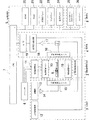
- FIG. 1 is a block diagram showing the overall configuration of an MRI apparatus to which the present invention is applied.
- This MRI apparatus uses a magnetic resonance phenomenon to obtain a tomographic image of a subject, and includes a static magnetic field generation magnetic circuit 1, a gradient magnetic field generation system 2, a transmission system 3, a reception system 4, and a signal processing system. 5, a sequencer 6, a central processing unit (CPU) 7, and an operation unit 8.
- CPU central processing unit
- the static magnetic field generating magnetic circuit 1 generates a uniform static magnetic field around the subject 9 in the direction of the body axis or in a direction perpendicular to the body axis.
- a permanent magnet type, normal conducting type or superconducting type magnetic field generating means is arranged in a space having a certain extent.
- the gradient magnetic field generation system 2 includes a gradient magnetic field coil 10 wound in three axial directions of X, Y, and Z, and a gradient magnetic field power source 11 that drives each coil.
- gradient magnetic fields Gs, Gp, and Gf are applied to the subject 9.
- the slice plane for the subject 9 can be set.
- the transmission system 3 irradiates a high-frequency signal to cause nuclear magnetic resonance to occur in the atomic nucleus constituting the biological tissue of the subject 9 by a high-frequency magnetic field pulse transmitted from the sequencer 6, and includes a high-frequency oscillator 12 and a modulator. 13, a high-frequency amplifier 14, and a high-frequency coil 15 on the transmission side.
- the high-frequency pulse output from the high-frequency oscillator 12 is amplified by the high-frequency amplifier 14 and then supplied to the high-frequency coil 15 disposed close to the subject 9.
- the subject 9 is irradiated with electromagnetic waves.
- the high-frequency coil 15 is a wide range imaging coil (hereinafter also referred to as a whole body coil) having a sensitivity region that almost covers the entire measurement space, and is used not only for transmission but also for reception.
- a wide range imaging coil hereinafter also referred to as a whole body coil
- the receiving system 4 detects an echo signal (NMR signal) emitted by nuclear magnetic resonance of the nucleus of the biological tissue of the subject 9, and receives a high-frequency coil 16, an amplifier 17, a quadrature detector 18, and an A on the receiving side. / D converter 19.
- the reception-only high-frequency coil 16 has a narrower sensitivity region than the wide-range imaging coil, and is disposed close to the subject 9 (region of interest). Such a high frequency coil 16 is called a local coil or a dedicated coil.
- the reception system switches between the high frequency coils 15 and 16 at the timing according to the command from the sequencer 6, and detects either The received nuclear magnetic resonance signal is received.
- the signal detected by the high frequency coil 15 or 16 is input to the A / D converter 19 through the amplifier 17 and the quadrature phase detector 18 and converted into a digital quantity.
- two series of collected data sampled by the quadrature phase detector 18 at the timing according to the command from the sequencer 6 is obtained, and the signal is sent to the signal processing system 5.
- the signal processing system 5 performs image reconstruction calculation using the echo signal detected by the reception system 4 and displays an image.
- the echo signal For the echo signal, Fourier transform, correction coefficient calculation, sensitivity distribution calculation, image reconstruction, etc. It comprises a CPU 7 that performs processing and control of the sequencer 6, various storage devices 20 to 24, and a display 24 that is a display unit that visualizes image data and displays it as a tomographic image.
- the storage device is, for example, a ROM (read-only memory) 20 that stores a program for performing image analysis processing and measurement over time and an invariant parameter used in the execution, measurement parameters, echo signals detected by the reception system 4, and interests.
- a magneto-optical device that temporarily stores an image used for region setting and stores parameters for setting the region of interest and the like, and a data storage unit for recording image data reconstructed by the CPU 7 It consists of disk 22 and magnetic disk 23.
- the sequencer 6 serves as a control means that repeatedly applies a high-frequency magnetic field pulse that causes nuclear magnetic resonance to atomic nuclei constituting the biological tissue of the subject 9 in a predetermined pulse sequence, and operates under the control of the CPU 7, Various commands necessary for collecting tomographic image data of the subject 9 are sent to the transmission system 3, the gradient magnetic field generation system 2, and the reception system 4. There are various types of pulse sequences depending on the purpose of imaging and measurement, and they are stored in advance in the signal processing system 5 as programs.
- the operation unit 8 is used to input control information for processing performed by the signal processing system 5, and includes a trackball 25 and a keyboard 26.
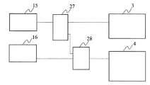
- Fig. 2 shows the details of the receiving system 4 provided with two or more high-frequency coils as a high-frequency coil for reception.
- one is a wide-range imaging coil (whole body coil) 15 that also serves as a transmission-side high-frequency coil, and the other is a dedicated coil 16 that is installed near the subject.
- the present invention is not limited to these, and one or both coils may be a multiple coil in which a plurality of small coils are arranged.
- the dedicated coil is a multiple coil composed of a plurality of small receiving coils, the same number of receiving systems 4 (amplifiers, quadrature phase detectors, A / D converters) as the number of the small receiving coils are provided.
- the wide range imaging coil 15 is connected to either the transmission system 3 or the reception system 4 via the transmission / reception changeover switch 27.
- the dedicated coil 16 is connected to the receiving system 4 via a coil changeover switch 28.
- the transmission / reception change-over switch 27 and the coil change-over switch 28 are schematically described as switches inserted between the coils 15 and 16 and the transmission system or the reception system. It is also possible to provide, as a switch means, a resonance circuit that switches the coil circuit between operation and non-operation in the power supply section of the required coil 16.
- the coil changeover switch is turned on / off in accordance with the control timing according to the pulse sequence.
- the gain of the receiver usually varies depending on the coil. It is decided together. In this embodiment, since the number of times of switching is large and the switching timing is very early, this switching may not be possible due to hardware restrictions. In this case, the smallest value among the values obtained for each coil is set, and the gain value is not changed during imaging and is kept constant.
- the present invention is applied to measurement of the sensitivity distribution of a receiving coil used for imaging (main imaging) for obtaining an image of a subject.
- the sensitivity distribution may be measured separately from the main imaging, or the sensitivity distribution can be measured using a signal acquired by the main imaging.
- the main imaging is not particularly limited, and can be applied to various imaging as long as the sensitivity distribution is used in image reconstruction.
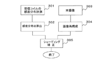
- imaging (step 301) for measuring the sensitivity distribution of the receiving coil is performed separately from the main imaging (step 303).
- sensitivity distribution measurement 301 imaging is performed using two types of receiving coils, a whole body coil and a dedicated coil, and a sensitivity distribution of the dedicated coil is calculated using images obtained by these two types of receiving coils (step 302).
- This imaging is performed using a dedicated coil, and the image obtained by the dedicated coil (step 304) is corrected using the sensitivity distribution of the dedicated coil obtained by the sensitivity distribution measurement 301 (step 305).
- the form of the dedicated coil is not particularly limited, and for example, a coil composed of a plurality of elements such as a multiple array coil or a combination of a plurality of small receiving coils may be used.
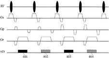
- FIG. 4 shows an example of a pulse sequence used for measuring the sensitivity distribution of the receiving coil.
- RF, Gs, Gp, and Gr indicate the application timing and intensity of the radio frequency pulse, slice direction gradient magnetic field pulse, phase encoding direction gradient magnetic field pulse, and readout direction gradient magnetic field pulse, respectively
- AD is the sampling time of the echo signal Is shown.
- This pulse sequence is a general gradient echo system sequence, except that the same encoding step is repeated for the number of reception coils (here, twice), and the reception coil is switched for each echo signal.
- black portions 401 and 403 are received by dedicated coils, and hatched portions 402 and 404 are received by whole body coils.
- the dedicated coil is a multiple coil composed of a plurality of small receiving coils, reception is simultaneously performed by the plurality of small receiving coils.
- RF is transmitted with a whole body coil.
- the echo signal is measured with a dedicated coil
- the whole body coil is switched from transmission to reception after applying a high frequency pulse, and the local coil is turned off and the echo signal is measured with the whole body coil.
- the whole-body coil is switched from reception to transmission, and the dedicated coil is turned on and received by the dedicated coil.
- a predetermined number of encoding steps are repeated to obtain data for filling the k-space for each coil.
- the size of the k space that is, the number of encoding steps, is 128, 256, etc. for imaging to obtain a normal subject image, but high imaging resolution is not required for imaging for obtaining the sensitivity distribution of the receiving coil. For example, 32 or 64 may be used.
- FIG. 4 shows the case where the step with the smallest gradient magnetic field in the phase encode direction is measured as the first encode step
- the measurement order of the k space is not particularly limited, and ⁇ kmax to + kmax are measured sequentially. Alternatively, it may be measured so as to be incremented one step at a time in the ⁇ direction and the + direction sequentially from the phase encode 0.
- Fig. 5 (a) shows the timing chart of the above measurement and an example of arrangement of k-space data.
- FIG. 5 shows the data space of one dedicated coil.
- the dedicated coil is a multiple coil
- k-space data is obtained for each receiving coil constituting the multiple coil.
- each of these k-space data is Fourier transformed to reconstruct an image.
- the sensitivity distribution of the dedicated coil is obtained by dividing the image obtained by the dedicated coil with the image obtained by the whole body coil according to the following equation (1).
- Sm and Sa indicate images obtained by the dedicated coil and the whole body coil, respectively
- Cm is a sensitivity distribution of m elements (small receiving coils) of the dedicated coil.
- Sm, Sa and Cm are complex data, and the subscripts r and i indicate the real part and the imaginary part of the complex data, respectively (hereinafter the same).
- the coil sensitivity C obtained by synthesizing each element of the dedicated coil can be obtained by the following equation (2).
- n is the number of elements of the multiple array coil.
- the sensitivity distribution thus obtained is obtained by acquiring the whole body coil image and the dedicated coil image used for the calculation substantially simultaneously. Not affected by changes in specimen position.
- the whole body coil and the dedicated coil acquire the same phase encoding signal almost simultaneously and divide it, so even if there is movement of the subject during imaging, the phase shift that appears in the signal as a result of movement can be eliminated And an extremely accurate sensitivity distribution can be obtained.
- the conventional method shown in FIG.5 (b) since the images of the respective coils are obtained by independent imaging, errors due to the positional deviation of the subject that may occur between the imaging are eliminated. It cannot be avoided, and even if division is performed, the influence of the movement of the subject being imaged cannot be removed.
- Figure 6 shows the division process.
- the images 601 and 602 captured by each receiving coil may have motion artifacts.
- these artifacts are generated in the same format, the influence of the artifacts is caused by the division process.
- a more accurate receiving coil sensitivity distribution 603 can be obtained.
- the main imaging 303 performed separately from the sensitivity distribution measurement described above can employ various known pulse sequences according to the imaging purpose, and a dedicated coil whose sensitivity distribution is measured is used as the reception coil.
- a dedicated coil whose sensitivity distribution is measured is used as the reception coil.
- parallel imaging a combination of a plurality of receiving coils having different sensitivity distributions is used.
- Various receiving coils suitable for parallel imaging have been proposed and known ones can be employed.
- M is the signal value of the receiving coil obtained by the actual imaging (m is the number of receiving coils), C is the sensitivity distribution for each field of view of each of the m receiving coils (n is the field number), and P1 to Pn are each
- m is the number of receiving coils
- C is the sensitivity distribution for each field of view of each of the m receiving coils (n is the field number)
- P1 to Pn are each
- Equation (3) shows an example of computation using real space data (image)
- reconstruction computation in parallel imaging also includes folding expansion computation using measurement space data. Can be used to obtain an accurate image free of artifacts as in the equation (3).
- the main imaging 303 is normal imaging without thinning out phase encoding.
- the dedicated coil used for this imaging is installed close to the region of interest, so it generally has higher sensitivity than the whole body coil, but the sensitive area is limited, and the sensitivity distribution is less uniform than the whole body coil. .
- the image obtained by this imaging has shading by the sensitivity distribution of a receiving coil.
- the shading is corrected by dividing the image M (x, y) obtained by the main imaging by the sensitivity distribution C (x, y) obtained in the sensitivity distribution calculation step 302 (formula (Four)).
- Expression (4) is the same as that calculated as the number of coils 1 in parallel imaging, and is equivalent to a combination of elements of the receiving coil by the sum of squares.
- the measurement image M (x, y) is divided using the coil sensitivity C (sensitivity for each pixel) obtained by combining the elements obtained by Equation (2). Sensitivity correction is performed.
- the sensitivity distribution Cm of each small receiving coil obtained by equation (1) is used to obtain the signal obtained by each small receiving coil in this imaging. It is also possible to synthesize an image by weighting Mm and using the following equation (5). In this case, the sensitivity distribution is used as a weight for signal synthesis.
- Msum is an image of the main image after synthesis.
- imaging for sensitivity distribution measurement is performed separately from the main imaging, and at that time, the whole body coil and the dedicated coil are used for the receiving coil, and reception is performed substantially simultaneously. Since the sensitivity distribution is calculated by dividing the image obtained from the received signal, an extremely accurate sensitivity distribution can be obtained even when there is movement of the subject during the sensitivity distribution measurement. Thereby, in this imaging, accurate folding expansion calculation, shading correction, or multiple coil synthesis can be performed using the sensitivity distribution.
- FIG. 4 illustrates a gradient echo two-dimensional pulse sequence.
- a 3D pulse sequence is used.
- slice encoding is added to the Gs axis in addition to the Gp (phase encoding) axis, and also for this slice encoding, the receiving coil is switched for each echo within the same slice encoding. That is, in the case of 3D, each of the slice encoding and the phase encoding is switched to both coils alternately for each increment and imaged.
- FIG. 4 shows an incoherent gradient echo sequence suitable for high-speed measurement, but the pulse sequence may be a spin echo sequence.
- the pulse sequence for sensitivity distribution measurement may be executed in combination with a known body movement suppression method.
- body movement suppression methods include, for example, measurement methods synchronized with biological signals such as breathing, electrocardiograms, and pulse waves, false image reduction methods using normal movement such as performing breath holding in several steps, belts, etc.
- measurement methods synchronized with biological signals such as breathing, electrocardiograms, and pulse waves
- false image reduction methods using normal movement such as performing breath holding in several steps, belts, etc.
- the case where two reception coils are switched in each encoding step is shown.
- the switching of the reception coil is not performed for each encoding, but two or more encoding steps are performed.
- the receiving coil is switched for each block as one block.
- it is desirable that the measurement time for one block is sufficiently fast with respect to the movement of the subject.
- FIG. 7 shows a timing chart in the case of switching two receiving coils every two steps.
- the echo signal is measured with the first receiving coil, for example, the whole body coil (701, 702), and then the gradient magnetic field condition is returned to the first encoding step.
- an echo signal is measured with a second receiving coil, for example, a dedicated coil (711, 712).
- the image of the first receiving coil (whole body coil) and the image of the second receiving coil (dedicated coil) were acquired substantially simultaneously, the deviation at the time of signal acquisition by both coils Therefore, an extremely accurate sensitivity distribution can be obtained without being substantially affected by the position change of the subject due to the movement of the subject and the movement of the subject during imaging.
- the obtained sensitivity distribution is used for correcting or synthesizing an image of main imaging performed separately from the sensitivity distribution as in the first embodiment.
- Modification Example of Example 1 and Example 2 In Example 1 and Example 2, the case where the reception by the first reception coil and the reception by the second reception coil are switched over the entire k space has been described.
- the receiving coil may be switched by dividing the k-space and measuring only a part of the region, for example, a low-frequency region. In that case, for example, in the low frequency region, the reception coil is alternately switched every step of phase encoding and slice encoding, and in the high frequency region, switching of the reception coil is performed only once or measurement in the low frequency region is performed. Measurement is performed at a lower frequency than in the case of.
- the image contrast is determined by the data in the low frequency region, and the sensitivity information is reflected in the data in the low frequency region. Therefore, even if the switching of the receiving coil is reduced in the high frequency region, it depends on the movement of the subject during that time. Not easily affected. Therefore, also in this modified example, as in the first and second embodiments, an accurate sensitivity distribution can be obtained by eliminating the influence of motion.
- Example 1 and Example 2 in the sensitivity distribution measurement, a single-echo pulse sequence for measuring one echo after one spin excitation was shown, but in this embodiment, a multi-echo sequence is adopted, and the same shot is used. Each of the plurality of echoes obtained in (1) is received by different receiving coils.
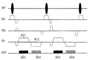
- FIG. 8 An example of the pulse sequence adopted in this embodiment is shown in FIG. 8 are the same as those in FIG. 4, black portions 801 and 803 of AD are received by a dedicated coil, and hatched portions 802 and 804 are received by a whole body coil.
- FIG. 8 shows a 2D gradient echo pulse sequence as in FIG. 4, but a 3D pulse sequence or a spin echo pulse sequence to which slice encoding is added may be used.
- the first readout gradient magnetic field pulse 811 and the second readout gradient magnetic field pulse 812 whose polarity is inverted are applied to each readout.
- An echo signal is measured during application of the gradient magnetic field pulse (801, 802).
- the receiving coil is switched for each echo, for example, the first echo signal is received by the whole body coil, and the second echo signal is received by the local coil.
- the receiving coil is switched between measurement of two echoes generated after one RF application while sequentially incrementing the encoding step, and the two echoes are received by different receiving coils.
- reconstructing an image using the signal measured for each reception coil and obtaining the sensitivity distribution of the reception coil from two images are the same as in the first embodiment. Also in this embodiment, as in the first and second embodiments, an accurate sensitivity distribution can be obtained by eliminating the influence of motion. In this embodiment, since echoes for two receiving coils are generated within the same phase encoding step, the measurement time can be shortened as compared with the first and second embodiments.
- FIG. 8 shows an example in which two echoes are generated, the number of echoes may be larger than two. For example, 4 echoes may be received and added by 2 echoes for each of the whole body coil and the dedicated coil.
- the imaging for measuring the sensitivity distribution is performed separately from the main imaging, but it is also possible to use the signal measured by the main imaging for the sensitivity distribution measurement.
- the procedure in that case is shown in FIG.
- a predetermined pulse sequence is executed using a whole-body coil and a dedicated coil as receiving coils.
- the pulse sequence may be a single echo sequence for measuring one echo in one shot or a multi-echo sequence.
- a multi-echo sequence is preferable in that the measurement time is not extended by repeating the encoding step twice.
- the signal obtained by the receiving coil is used to create an image of the subject, the number of encodings that can obtain the spatial resolution required for the subject image is used.
- the reception coil is switched between the whole body coil and the dedicated coil for each phase encoding step or for each block including a plurality of encoding steps. This is the same as in the first to third embodiments, and all encoded data may be obtained for both the whole body coil and the dedicated coil.
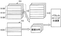
- the receiving coil may be switched only during measurement in the low frequency region, and as shown in FIG. 10, only the low frequency region data 502A may be acquired for the whole body coil.
- the k-space data 502 measured with the whole-body coil and the k-space data 501 measured with the dedicated coil are obtained in the present embodiment as shown in FIG.
- An image is reconstructed using the data, and the sensitivity distribution of the dedicated coil is obtained by dividing (step 902). Prior to division, the obtained image is subjected to a filtering process using an LPF or the like as necessary.
- the k-space data of the dedicated coil used for calculating the sensitivity distribution is the same low frequency region data 501A as the whole body coil data.
- the calculation for obtaining the sensitivity distribution is the same as that in the first embodiment, and the sensitivity distribution of the dedicated coil is calculated by the equation (1) or the equation (2).
- an image is reconstructed using k-space data obtained by the dedicated coil (step 903).
- the image is subjected to shading correction using the sensitivity distribution obtained in step 902 (step 904).
- the dedicated coil is a multiple coil
- the image of each small receiving coil is synthesized using each small receiving coil sensitivity distribution constituting the weight as a weight.
- the measurement time as a whole can be shortened as compared with the case where the sensitivity distribution measurement is separately performed.
- the sensitivity distribution measurement is performed using the echo signal measured in the main imaging even when the main imaging is parallel imaging in which phase encoding is thinned out. It is possible to do.
- data 501A and 502A are collected by the whole body coil and the dedicated coil without thinning out the phase encoding, and the data in that region are used for calculation of the sensitivity distribution.
- the dedicated coil is composed of a plurality (m in the figure) of receiving coils, and thus the sensitivity distribution is calculated for each of the plurality of receiving coils.
- the data 501 of the dedicated coil measured by thinning out the phase encoding that is, the data acquired with the same encoding step width as the data of the high frequency region among the data 501B of the high frequency region and the low frequency region data 501A, and the sensitivity distribution of the dedicated coil can be used to make a change such as obtaining an image by performing folding development by parallel imaging.
- a 2D pulse sequence can be changed to a 3D sequence, and the k-space measurement order may be sequential or centric.
- the influence of the movement of the subject during imaging can be greatly reduced, and an accurate sensitivity distribution of the receiving coil can be obtained.
- the aliasing calculation in shading correction and parallel imaging can be performed accurately, and an image free from artifacts can be obtained.
Landscapes
- Physics & Mathematics (AREA)
- Condensed Matter Physics & Semiconductors (AREA)
- General Physics & Mathematics (AREA)
- Health & Medical Sciences (AREA)
- General Health & Medical Sciences (AREA)
- Nuclear Medicine, Radiotherapy & Molecular Imaging (AREA)
- Radiology & Medical Imaging (AREA)
- Engineering & Computer Science (AREA)
- Signal Processing (AREA)
- High Energy & Nuclear Physics (AREA)
- Magnetic Resonance Imaging Apparatus (AREA)
Abstract
Description
図1は本発明が適用されるMRI装置の全体構成を示すブロック図である。このMRI装置は、磁気共鳴現象を利用して被検体の断層像を得るもので、静磁場発生磁気回路1と、傾斜磁場発生系2と、送信系3と、受信系4と、信号処理系5と、シーケンサ6と、中央処理装置(CPU)7と、操作部8とを備えている。
図4に、受信コイルの感度分布を計測に用いるパルスシーケンスの一例を示す。図中、RF、Gs、Gp、Grは、それぞれ高周波パルス、スライス方向傾斜磁場パルス、位相エンコード方向傾斜磁場パルス、リードアウト方向傾斜磁場パルスの印加タイミング及び強度を示し、ADはエコー信号のサンプリング時間を示している。このパルスシーケンスは、一般的なグラディエントエコー系のシーケンスであるが、同一エンコードステップを、受信コイルの数(ここでは2回)繰り返し、その中でエコー信号毎に受信コイルを切替える点が異なる。ADのうち、黒塗り部分401、403は専用コイルによる受信、斜線部分402、404は全身コイルによる受信である。専用コイルが複数の小型受信コイルからなるマルチプルコイルの場合には、複数の小型受信コイルで同時に受信が行なわれる。RFは、全身コイルで送信する。


なお式(1)或いは(2)の計算において、被写体が無い領域は、予め領域を識別して除算処理を行わずに、求められた感度分布から補間処理によって計算することが望ましい。



実施例1および実施例2の変更例
実施例1及び実施例2では、k空間の全域に亘って、第1の受信コイルによる受信と第2の受信コイルによる受信を切替える場合について説明したが、k空間を分割し、一部の領域例えば低周波数領域の計測のみで、受信コイルの切替を行なってもよい。その場合に、例えば、低周波数領域については、位相エンコードおよびスライスエンコードのステップ毎に受信コイルを交互に切替え、高周波数領域については、受信コイルの切替を1回とするか、低周波数領域の計測の場合よりも低頻度として計測を行なう。
Claims (20)
- 静磁場発生手段と、前記静磁場発生手段が発生する静磁場に磁場勾配を生成する傾斜磁場発生手段と、静磁場中に置かれた検査対象に高周波磁場を印加する高周波磁場送信手段と、前記検査対象から発生する核磁気共鳴信号を受信する受信手段と、前記傾斜磁場発生手段、高周波磁場送信手段および受信手段を制御する制御手段と、前記核磁気共鳴信号を処理する信号処理手段とを備えた磁気共鳴イメージング装置において、
前記受信手段は、第1の受信コイルと、前記第1の受信コイルの感度領域を含み前記第1の受信コイルより広い感度領域を持つ第2の受信コイルとを備え、
前記制御手段は、傾斜磁場の印加量を順次変化させながら、k空間データに対応する数のエンコードステップを実行して、複数の核磁気共鳴信号からなるデータを取得する制御を行い、その際、少なくとも一部のエンコードステップにおいて、1ないし複数の核磁気共鳴信号の組毎に前記第1の受信コイルによる受信と前記第2の受信コイルによる受信を交互に切替えることを特徴とする磁気共鳴イメージング装置。 - 請求項1に記載の磁気共鳴イメージング装置において、
前記第2の受信コイルは、前記高周波磁場送信手段に備えられた送信用コイルを兼ねる全身コイルであることを特徴とする磁気共鳴イメージング装置。 - 請求項1に記載の磁気共鳴イメージング装置において、
前記第1の受信コイルは、前記被検体の関心領域からの信号を受信する局所コイルであることを特徴とする磁気共鳴イメージング装置。 - 請求項3に記載の磁気共鳴イメージング装置において、
前記第1の受信コイルは、互いに感度分布領域の異なる複数の小型受信コイルからなるマルチプルコイルであることを特徴とする磁気共鳴イメージング装置。 - 請求項1に記載の磁気共鳴イメージング装置において、
前記制御手段は、k空間データに対応する数のエンコードステップのうち、k空間の低周波領域データを収集するステップで、前記第1の受信コイルによる受信と第2の受信コイルによる受信とを切替えることを特徴とする磁気共鳴イメージング装置。 - 請求項1に記載の磁気共鳴イメージング装置において、
前記制御手段は、1のエンコードステップで2以上の核磁気共鳴信号を取得するマルチエコーシーケンスを実行し、当該2以上の核磁気共鳴信号のうち一つを第1の受信コイルで、他の一つを第2の受信コイルで受信するように制御することを特徴とする磁気共鳴イメージング装置。 - 請求項1に記載の磁気共鳴イメージング装置において、
前記信号処理手段は、前記第1の受信コイルが受信した核磁気共鳴信号と、前記第2の受信コイルが受信した核磁気共鳴信号とを用いて前記第1の受信コイルの感度分布を算出する感度分布算出手段を備えたことを特徴とする磁気共鳴イメージング装置。 - 請求項7に記載の磁気共鳴イメージング装置において、
前記感度分布算出手段は、前記第1の受信コイルが受信した核磁気共鳴信号から作成した画像と、前記第2の受信コイルが受信した核磁気共鳴信号から作成した画像とを除算することにより前記第1の受信コイルの感度分布を算出することを特徴とする磁気共鳴イメージング装置。 - 請求項7に記載の磁気共鳴イメージング装置において、
前記制御手段は、前記第1の受信コイルを用いて前記被検体の生体情報を画像化するための核磁気共鳴信号を取得する撮像を制御する本撮像手段を備え、
前記信号処理手段は、前記本撮像手段による撮像で取得した核磁気共鳴信号と前記感度分布算出手段が算出した第1の受信コイルの感度分布を用いて前記被検体の生体情報の画像を生成する画像生成手段を備えることを特徴とする磁気共鳴イメージング装置。 - 請求項9に記載の磁気共鳴イメージング装置において、
前記制御手段は、前記第1の受信コイルによる受信と前記第2の受信コイルによる受信の切替を、前記本撮像手段による撮像において実行することを特徴とする磁気共鳴イメージング装置。 - 請求項9に記載の磁気共鳴イメージング装置において、
前記制御手段は、前記本撮像とは別に、前記第1の受信コイルの感度分布を計測するための核磁気共鳴信号を取得する計測を実行する感度分布計測手段を備え、前記感度分布計測手段による計測において、前記第1の受信コイルによる受信と前記第2の受信コイルによる受信の切替を行なうことを特徴とする磁気共鳴イメージング装置。 - 請求項9に記載の磁気共鳴イメージング装置であって、
前記第1の受信コイルは、前記被検体の関心領域からの信号を受信する局所コイルであり、
前記信号処理手段は、前記感度分布算出手段が算出した局所コイルの感度分布を用いて、前記本撮像手段で取得した核磁気共鳴信号から生成した画像のシェーディング補正を行なう補正手段を備えることを特徴とする磁気共鳴イメージング装置。 - 請求項9に記載の磁気共鳴イメージング装置であって、
前記第1の受信コイルは、互いに感度分布領域の異なる複数の小型受信コイルからなるマルチプルコイルであり、
前記本撮像手段は、k空間データに対応する数のエンコードステップよりも少ない数のエンコードステップを実行して、画像の折り返しを生じうる核磁気共鳴信号を収集し、
前記信号処理手段は、前記本撮像手段で取得した核磁気共鳴信号を用いて画像を生成する際に、前記感度分布算出手段が算出した各小型受信コイルの感度分布を用いて折り返しのない画像を生成することを特徴とする磁気共鳴イメージング装置。 - 請求項1に記載の磁気共鳴イメージング装置であって、
前記受信手段は、受信コイルの受信ゲインを計測するゲイン計測手段を備え、
前記制御手段は、前記第1の受信コイルによる受信と第2の受信コイルによる受信を切替える際に、前記受信手段の受信ゲインを、前記ゲイン計測手段が計測した各受信コイルの受信ゲインのうち最小の受信ゲインに設定することを特徴とする磁気共鳴イメージング装置。 - 請求項1に記載の磁気共鳴イメージング装置であって、
さらに、前記被検体の周期的動きを計測する手段からの信号を入力する周期動信号入力手段を備え、
前記制御手段は、前記第1の受信コイルによる受信と前記第2の受信コイルによる受信との切替を伴う核磁気共鳴信号の計測において、前記周期動信号入力手段が入力した信号に同期して核磁気共鳴信号の計測を行なうことを特徴とする磁気共鳴イメージング装置。 - 第1の受信コイルと、前記第1の受信コイルの感度領域を含み前記第1の受信コイルより広い感度領域を持つ第2の受信コイルとを用いた磁気共鳴イメージング方法において、
傾斜磁場の印加量を順次変化させながら、k空間データに対応する数のエンコードステップを実行して、複数の核磁気共鳴信号からなるデータを取得する制御を行い、その際、少なくとも一部のエンコードステップにおいて、1ないし複数の核磁気共鳴信号の組毎に前記第1の受信コイルによる受信と前記第2の受信コイルによる受信を交互に切替えることを特徴とする磁気共鳴イメージング方法。 - 請求項16に記載の磁気共鳴イメージング方法において、
前記第2の受信コイルは、前記高周波磁場送信手段に備えられた送信用コイルを兼ねる全身コイルであることを特徴とする磁気共鳴イメージング方法。 - 請求項16に記載の磁気共鳴イメージング方法において、
前記第1の受信コイルは、前記被検体の関心領域からの信号を受信する局所コイルであることを特徴とする磁気共鳴イメージング方法。 - 請求項18に記載の磁気共鳴イメージング方法において、
前記第1の受信コイルは、互いに感度分布領域の異なる複数の小型受信コイルからなるマルチプルコイルであることを特徴とする磁気共鳴イメージング方法。 - 請求項16に記載の磁気共鳴イメージング方法において、
k空間データに対応する数のエンコードステップのうち、k空間の低周波領域データを収集するステップで、前記第1の受信コイルによる受信と第2の受信コイルによる受信とを切替えることを特徴とする磁気共鳴イメージング方法。
Priority Applications (2)
| Application Number | Priority Date | Filing Date | Title |
|---|---|---|---|
| JP2011504852A JP5722212B2 (ja) | 2009-03-18 | 2010-03-17 | 磁気共鳴イメージング装置及び方法 |
| US13/257,124 US9157978B2 (en) | 2009-03-18 | 2010-03-17 | Magnetic resonance imaging apparatus and method |
Applications Claiming Priority (2)
| Application Number | Priority Date | Filing Date | Title |
|---|---|---|---|
| JP2009-066476 | 2009-03-18 | ||
| JP2009066476 | 2009-03-18 |
Publications (1)
| Publication Number | Publication Date |
|---|---|
| WO2010107041A1 true WO2010107041A1 (ja) | 2010-09-23 |
Family
ID=42739701
Family Applications (1)
| Application Number | Title | Priority Date | Filing Date |
|---|---|---|---|
| PCT/JP2010/054489 Ceased WO2010107041A1 (ja) | 2009-03-18 | 2010-03-17 | 磁気共鳴イメージング装置及び方法 |
Country Status (3)
| Country | Link |
|---|---|
| US (1) | US9157978B2 (ja) |
| JP (1) | JP5722212B2 (ja) |
| WO (1) | WO2010107041A1 (ja) |
Cited By (4)
| Publication number | Priority date | Publication date | Assignee | Title |
|---|---|---|---|---|
| JP2010233907A (ja) * | 2009-03-31 | 2010-10-21 | Hitachi Medical Corp | 磁気共鳴イメージング装置及び感度補正方法 |
| JP2016010555A (ja) * | 2014-06-30 | 2016-01-21 | ジーイー・メディカル・システムズ・グローバル・テクノロジー・カンパニー・エルエルシー | 磁気共鳴信号処理方法、磁気共鳴信号処理装置及び磁気共鳴装置並びにプログラム |
| KR20180088194A (ko) * | 2017-01-26 | 2018-08-03 | 삼성전자주식회사 | 자기 공명 영상 획득 방법 및 그 자기 공명 영상 장치 |
| US20230306656A1 (en) * | 2022-03-28 | 2023-09-28 | Shanghai United Imaging Healthcare Co., Ltd. | Systems and methods for mri data processing |
Families Citing this family (2)
| Publication number | Priority date | Publication date | Assignee | Title |
|---|---|---|---|---|
| DE102014226034B4 (de) | 2014-12-16 | 2017-01-19 | Siemens Healthcare Gmbh | Bildkorrektur bei der MR-Bildgebung unter Berücksichtigung des Empfangsprofils |
| JP7608268B2 (ja) * | 2021-05-20 | 2025-01-06 | 富士フイルム株式会社 | 磁気共鳴撮影装置及び感度分布算出プログラム |
Citations (2)
| Publication number | Priority date | Publication date | Assignee | Title |
|---|---|---|---|---|
| JP2000023938A (ja) * | 1998-07-15 | 2000-01-25 | Shimadzu Corp | Mrイメージング装置 |
| JP2008005943A (ja) * | 2006-06-28 | 2008-01-17 | Hitachi Medical Corp | 磁気共鳴イメージング装置 |
Family Cites Families (3)
| Publication number | Priority date | Publication date | Assignee | Title |
|---|---|---|---|---|
| JP2575352B2 (ja) * | 1985-09-27 | 1997-01-22 | 株式会社東芝 | 磁気共鳴イメ−ジング装置 |
| JP4202855B2 (ja) * | 2003-07-25 | 2008-12-24 | 株式会社日立メディコ | 磁気共鳴イメージング装置 |
| JP2009240767A (ja) * | 2008-03-10 | 2009-10-22 | Toshiba Corp | 磁気共鳴イメージング装置 |
-
2010
- 2010-03-17 WO PCT/JP2010/054489 patent/WO2010107041A1/ja not_active Ceased
- 2010-03-17 JP JP2011504852A patent/JP5722212B2/ja active Active
- 2010-03-17 US US13/257,124 patent/US9157978B2/en active Active
Patent Citations (2)
| Publication number | Priority date | Publication date | Assignee | Title |
|---|---|---|---|---|
| JP2000023938A (ja) * | 1998-07-15 | 2000-01-25 | Shimadzu Corp | Mrイメージング装置 |
| JP2008005943A (ja) * | 2006-06-28 | 2008-01-17 | Hitachi Medical Corp | 磁気共鳴イメージング装置 |
Cited By (7)
| Publication number | Priority date | Publication date | Assignee | Title |
|---|---|---|---|---|
| JP2010233907A (ja) * | 2009-03-31 | 2010-10-21 | Hitachi Medical Corp | 磁気共鳴イメージング装置及び感度補正方法 |
| JP2016010555A (ja) * | 2014-06-30 | 2016-01-21 | ジーイー・メディカル・システムズ・グローバル・テクノロジー・カンパニー・エルエルシー | 磁気共鳴信号処理方法、磁気共鳴信号処理装置及び磁気共鳴装置並びにプログラム |
| CN106574951A (zh) * | 2014-06-30 | 2017-04-19 | Ge医疗系统环球技术有限公司 | 磁共振信号处理方法、磁共振信号处理装置和磁共振装置以及程序 |
| US10156617B2 (en) | 2014-06-30 | 2018-12-18 | General Electric Company | Magnetic resonance signal processing method, magnetic resonance signal processing apparatus and magnetic resonance apparatus, and program |
| CN106574951B (zh) * | 2014-06-30 | 2019-10-22 | Ge医疗系统环球技术有限公司 | 磁共振信号处理方法、装置和磁共振装置 |
| KR20180088194A (ko) * | 2017-01-26 | 2018-08-03 | 삼성전자주식회사 | 자기 공명 영상 획득 방법 및 그 자기 공명 영상 장치 |
| US20230306656A1 (en) * | 2022-03-28 | 2023-09-28 | Shanghai United Imaging Healthcare Co., Ltd. | Systems and methods for mri data processing |
Also Published As
| Publication number | Publication date |
|---|---|
| US20120019248A1 (en) | 2012-01-26 |
| US9157978B2 (en) | 2015-10-13 |
| JP5722212B2 (ja) | 2015-05-20 |
| JPWO2010107041A1 (ja) | 2012-09-20 |
Similar Documents
| Publication | Publication Date | Title |
|---|---|---|
| JP5980126B2 (ja) | 単一および多重チャネル受信コイルを用いた同時マルチスライス磁気共鳴画像法 | |
| US8344729B2 (en) | Magnetic resonance imaging apparatus | |
| JP6084573B2 (ja) | マルチポイントディクソン技術を用いるmr撮像 | |
| US10444315B2 (en) | MRI with motion correction using navigators acquired using a dixon technique | |
| US9396562B2 (en) | MRI reconstruction with incoherent sampling and redundant haar wavelets | |
| RU2557334C2 (ru) | Динамическая контрастная улучшенная мр визуализация с реконструкцией сжатого измерения | |
| CN102670201B (zh) | 用于产生磁共振图像数据的方法和磁共振断层造影系统 | |
| US10203394B2 (en) | Metal resistant MR imaging | |
| JP5599893B2 (ja) | ナビゲータを使用するmrイメージング | |
| JP5196408B2 (ja) | 多重ピークを備えた種の磁気共鳴スペクトロスコピー | |
| CN106574954A (zh) | 针对epi的具有奈奎斯特伪影校正的并行mr成像 | |
| CN105103001A (zh) | 使用高snr同相图像和较低snr至少部分地异相图像的dixon型水/脂肪分离mri | |
| JP5722212B2 (ja) | 磁気共鳴イメージング装置及び方法 | |
| JP2000157507A (ja) | 核磁気共鳴撮影装置 | |
| JP5337406B2 (ja) | 磁気共鳴イメージング装置 | |
| JP4343317B2 (ja) | 磁気共鳴イメージング装置 | |
| JP2010233907A (ja) | 磁気共鳴イメージング装置及び感度補正方法 | |
| JP4698231B2 (ja) | 磁気共鳴診断装置 | |
| JP4675936B2 (ja) | 核磁気共鳴撮影装置 | |
| JP4391214B2 (ja) | 磁気共鳴イメージング装置 | |
| JP5421600B2 (ja) | 核磁気共鳴イメージング装置および核磁気共鳴イメージング装置の作動方法 | |
| JP3983792B2 (ja) | 核磁気共鳴撮影装置 | |
| JP5484001B2 (ja) | 磁気共鳴イメージング装置及び画像補正方法 | |
| JP3952310B2 (ja) | 核磁気共鳴撮影装置 | |
| JP2002065634A (ja) | Mrイメージング装置 |
Legal Events
| Date | Code | Title | Description |
|---|---|---|---|
| 121 | Ep: the epo has been informed by wipo that ep was designated in this application |
Ref document number: 10753533 Country of ref document: EP Kind code of ref document: A1 |
|
| WWE | Wipo information: entry into national phase |
Ref document number: 2011504852 Country of ref document: JP |
|
| NENP | Non-entry into the national phase |
Ref country code: DE |
|
| WWE | Wipo information: entry into national phase |
Ref document number: 13257124 Country of ref document: US |
|
| 122 | Ep: pct application non-entry in european phase |
Ref document number: 10753533 Country of ref document: EP Kind code of ref document: A1 |