WO2010106826A1 - 光生体計測装置及び解析方法 - Google Patents
光生体計測装置及び解析方法 Download PDFInfo
- Publication number
- WO2010106826A1 WO2010106826A1 PCT/JP2010/050205 JP2010050205W WO2010106826A1 WO 2010106826 A1 WO2010106826 A1 WO 2010106826A1 JP 2010050205 W JP2010050205 W JP 2010050205W WO 2010106826 A1 WO2010106826 A1 WO 2010106826A1
- Authority
- WO
- WIPO (PCT)
- Prior art keywords
- signal
- light
- independent component
- signals
- component
- Prior art date
- Legal status (The legal status is an assumption and is not a legal conclusion. Google has not performed a legal analysis and makes no representation as to the accuracy of the status listed.)
- Ceased
Links
Images



Classifications
-
- A—HUMAN NECESSITIES
- A61—MEDICAL OR VETERINARY SCIENCE; HYGIENE
- A61B—DIAGNOSIS; SURGERY; IDENTIFICATION
- A61B5/00—Measuring for diagnostic purposes; Identification of persons
- A61B5/145—Measuring characteristics of blood in vivo, e.g. gas concentration or pH-value ; Measuring characteristics of body fluids or tissues, e.g. interstitial fluid or cerebral tissue
- A61B5/1455—Measuring characteristics of blood in vivo, e.g. gas concentration or pH-value ; Measuring characteristics of body fluids or tissues, e.g. interstitial fluid or cerebral tissue using optical sensors, e.g. spectral photometrical oximeters
- A61B5/14551—Measuring characteristics of blood in vivo, e.g. gas concentration or pH-value ; Measuring characteristics of body fluids or tissues, e.g. interstitial fluid or cerebral tissue using optical sensors, e.g. spectral photometrical oximeters for measuring blood gases
- A61B5/14553—Measuring characteristics of blood in vivo, e.g. gas concentration or pH-value ; Measuring characteristics of body fluids or tissues, e.g. interstitial fluid or cerebral tissue using optical sensors, e.g. spectral photometrical oximeters for measuring blood gases specially adapted for cerebral tissue
-
- A—HUMAN NECESSITIES
- A61—MEDICAL OR VETERINARY SCIENCE; HYGIENE
- A61B—DIAGNOSIS; SURGERY; IDENTIFICATION
- A61B5/00—Measuring for diagnostic purposes; Identification of persons
- A61B5/0033—Features or image-related aspects of imaging apparatus, e.g. for MRI, optical tomography or impedance tomography apparatus; Arrangements of imaging apparatus in a room
- A61B5/004—Features or image-related aspects of imaging apparatus, e.g. for MRI, optical tomography or impedance tomography apparatus; Arrangements of imaging apparatus in a room adapted for image acquisition of a particular organ or body part
- A61B5/0042—Features or image-related aspects of imaging apparatus, e.g. for MRI, optical tomography or impedance tomography apparatus; Arrangements of imaging apparatus in a room adapted for image acquisition of a particular organ or body part for the brain
-
- A—HUMAN NECESSITIES
- A61—MEDICAL OR VETERINARY SCIENCE; HYGIENE
- A61B—DIAGNOSIS; SURGERY; IDENTIFICATION
- A61B5/00—Measuring for diagnostic purposes; Identification of persons
- A61B5/72—Signal processing specially adapted for physiological signals or for diagnostic purposes
- A61B5/7235—Details of waveform analysis
- A61B5/7253—Details of waveform analysis characterised by using transforms
- A61B5/7257—Details of waveform analysis characterised by using transforms using Fourier transforms
-
- A—HUMAN NECESSITIES
- A61—MEDICAL OR VETERINARY SCIENCE; HYGIENE
- A61B—DIAGNOSIS; SURGERY; IDENTIFICATION
- A61B2562/00—Details of sensors; Constructional details of sensor housings or probes; Accessories for sensors
- A61B2562/02—Details of sensors specially adapted for in-vivo measurements
- A61B2562/0233—Special features of optical sensors or probes classified in A61B5/00
-
- A—HUMAN NECESSITIES
- A61—MEDICAL OR VETERINARY SCIENCE; HYGIENE
- A61B—DIAGNOSIS; SURGERY; IDENTIFICATION
- A61B2562/00—Details of sensors; Constructional details of sensor housings or probes; Accessories for sensors
- A61B2562/04—Arrangements of multiple sensors of the same type
- A61B2562/046—Arrangements of multiple sensors of the same type in a matrix array
Definitions
- the present invention relates to an optical biological measurement apparatus and an analysis method for acquiring an observation signal indicating a temporal change related to a measurement site using light.
- the present invention is used as an optical brain functional imaging device that measures the activity state of a measurement site in the brain non-invasively using near-infrared light, and an oxygen monitor that monitors the oxygen consumption of the measurement site in a living body. .
- the hemoglobin concentration is obtained from the amount of light obtained by transmitting through the living body by irradiating the living body with light having a wavelength from visible light to the near infrared region. Furthermore, hemoglobin binds to oxygen to become oxyhemoglobin, while away from oxygen to deoxyhemoglobin. It is also known that in the brain, oxygen is supplied to a site activated by blood flow redistribution, and the concentration of oxyhemoglobin combined with oxygen increases.
- the oxyhemoglobin concentration is determined using near infrared light of two different wavelengths (for example, 780 nm and 850 nm). Each deoxyhemoglobin concentration can be determined.
- an optical measurement device including a holder (a light transmitting / receiving unit) having a plurality of light transmitting probes and a plurality of light receiving probes has been developed (see, for example, Patent Document 1).
- a holder a light transmitting / receiving unit
- near infrared light is irradiated to the brain by a light transmission probe arranged on the scalp surface of the subject, and near infrared light emitted from the brain is emitted by a light receiving probe arranged on the scalp surface. Detect the amount of light.
- the holder is provided with a plurality of through-holes, and the distance (channel) between the light-transmitting probe and the light-receiving probe becomes constant by inserting the light-transmitting probe and the light-receiving probe into those through-holes.
- the light quantity (light detection signal) can be obtained from a plurality of brain parts at a specific depth from the scalp surface.
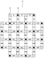
- FIG. 2 is a plan view showing the positional relationship between the 16 light transmitting probes and the 16 light receiving probes in the holder.
- the light transmitting probes 12 and the light receiving probes 13 are arranged in a square lattice pattern so as to alternate in the row direction and the column direction. Since the holder 11 is designed in consideration of the distance from the scalp to the brain, if the subject is an adult, the holder 11 has a distance (channel) of 30 mm between the light transmitting probe 12 and the light receiving probe 13. It is used. When the channel is 30 mm, it is considered that a light detection signal can be obtained from a position having a depth of 15 mm to 20 mm from the midpoint of the channel.
- a position 15 to 20 mm deep from the scalp surface substantially corresponds to the brain surface region, and 52 light detection signals indicating temporal changes with respect to 52 brain surface regions (# 1 to # 52) are obtained.
- the light irradiated from the light transmission probe 12 is detected also by the light receiving probes 13 other than the adjacent light receiving probes 13, here, in order to simplify the description, the light is detected only by the adjacent light receiving probes 13. I will do it.
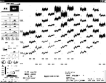
- FIG. 3 is a diagram showing a monitor screen on which 52 (# 1 to # 52) oxyhemoglobin concentrations X n (t) are displayed by the optical biometric apparatus.
- the vertical axis in one observation signal X n (t) indicates the oxyhemoglobin concentration, and the horizontal axis indicates time t.
- the 52 observation signals X n (t) displayed as shown in FIG. 3 are based on changes in skin blood flow, heart rate variability, pulsation / respiration, etc., in addition to signals based on blood flow accompanying brain activation.
- the signal is also superimposed. Therefore, an observer such as a doctor can easily examine whether or not a medical condition such as cerebral ischemia has occurred, and a signal based on a blood flow associated with brain activation in the observation signal X n (t).
- the visual evaluation is performed to distinguish the other signals. For example, only a signal synchronized with a task is treated as a brain activation signal, or a signal that is unlikely to be a physiological change in the brain is treated as an artifact.
- the observation signal X n (t) is statistically analyzed with a linear linear model (GLM) and compared with a reference observation signal.
- LLM linear linear model
- P value the statistical significance evaluation amount
- the brain activity of the subject when exercise such as walking is given as a task, the heart rate changes, and the signal based on the change in skin blood flow is also taken into the task. Therefore, if only a signal synchronized with a task is treated as a brain activation signal, it may not be possible to accurately diagnose whether or not a medical condition such as cerebral ischemia has occurred.
- the similarity and the evaluation amount for observation signal X n (t) is (P value) is known, the observed signal X n (t) is the signal based on the blood flow caused by the brain activation
- signals based on changes in skin blood flow since signals based on changes in skin blood flow, heart rate variability, pulsation, respiration, etc.
- an object of the present invention is to provide an optical biological measurement apparatus and an analysis method that can remove a signal corresponding to an unnecessary component from an observation signal.
- An optical biometric device of the present invention made to solve the above-described problems has a plurality of light-transmitting probes arranged on the skin surface of a subject and a plurality of light-receiving probes arranged on the skin surface.
- a time-dependent change with respect to the measurement site in the subject by controlling the light transmitting / receiving unit and the light transmitting probe to irradiate light on the skin surface and to detect the light emitted from the skin surface by the light receiving probe.
- An optical biological measurement apparatus comprising: a transmission / reception unit control unit that acquires an observation signal indicating a signal; and a calculation unit that creates an unnecessary component removal observation signal by removing a signal corresponding to an unnecessary component from the observation signal
- the calculation unit includes a mixing matrix generation unit that separates a plurality of observation signals into a product of a mixing matrix and a plurality of independent component signals by independent component analysis, and a plurality of functions that are functions of time and intensity.
- the “observation signal” may be a light detection signal detected by a light receiving probe, or an oxyhemoglobin concentration, deoxyhemoglobin concentration, or total hemoglobin concentration calculated from the light detection signal.
- the “signal corresponding to the unnecessary component” means a signal other than a signal based on blood flow accompanying brain activation, for example, a signal based on skin blood flow, a signal based on heartbeat variability, A signal based on respiration.
- the “predetermined frequency band” refers to an arbitrary frequency band that is set in advance.
- the “predetermined frequency band” is a frequency band (0.03 to 0.15 Hz) indicating skin blood flow.
- a frequency band (0.8 to 2.0 Hz) indicating pulsation / respiration, and the like are set.
- the light transmission / reception unit control unit controls the light transmission probe to irradiate light on the skin surface and controls the light reception probe to detect light emitted from the skin surface.
- N observation signals X n (t) relating to N measurement sites are acquired. Note that the observation signal X n (t) is superimposed with a signal based on changes in skin blood flow, heart rate variability, pulsation, respiration, and the like in addition to a signal based on blood flow accompanying brain activation.
- the calculation unit removes a signal corresponding to an unnecessary component from the observation signal X n (t).
- the mixing matrix creation unit converts N observation signals X n (t) into N ⁇ N mixing matrices and N independent components by independent component analysis (ICA). Separated into products with signal S n (t).
- ICA independent component analysis
- the column vector in the mixing matrix represents the weight of the specific independent component signal S n (t) at the measurement site. That is, the observed signal X n (t) is obtained by linearly combining N independent component signals S n (t) from independent signal generation sources using each element of the mixing matrix as a weighting factor. Become.
- any of N independent component signals S n (t) is: It is considered that the signal is based on the skin blood flow from the signal generation source. In general signal based on skin blood flow, it has been found to be present on a given frequency band lambda 1. Therefore, in order to find the independent component signal S n (t) corresponding to the unnecessary component from among the N independent component signals S n (t), the power spectrum calculation unit performs the N independent component signals S n.
- N transformed independent component signals S n ( ⁇ ) are created by performing a Fourier transform on (t).
- the unnecessary component signal determining unit compares the N power spectra S n ( ⁇ 1 ) with the threshold T, thereby eliminating the unnecessary component signal S n (t) from the N independent component signals S n (t). Find the independent component signal S n (t) corresponding to the component. For example, when the power spectrum S 1 ( ⁇ 1 ) is greater than or equal to the threshold T, the independent component signal S 1 (t) is determined to be a signal corresponding to an unnecessary component, while the power spectrum S 1 ( ⁇ 1).
- the independent component signal S 1 (t) is a signal based on blood flow accompanying brain activation. Note that the number determined to be a signal corresponding to an unnecessary component is not limited to one and may be plural.
- a signal corresponding to an unnecessary component can be removed from the observation signal X n (t).
- the calculation unit corresponds to an unnecessary component in the mixing matrix based on an independent component signal corresponding to an unnecessary component found by the unnecessary component signal determination unit.
- An unnecessary component removal mixing matrix creating unit that creates an unnecessary component removal mixing matrix in which 0 is substituted into a column vector to be performed, an unnecessary component removal mixing matrix, and a plurality of independent component signals are integrated, thereby obtaining a plurality of unnecessary component removal mixing matrices. You may make it provide the unnecessary component removal observation signal preparation part which produces a necessary component removal observation signal.
- the unnecessary component removal mixing matrix creation unit is based on the independent component signal S n (t) corresponding to the unnecessary component found by the unnecessary component signal determination unit.
- an N ⁇ N unnecessary component removal mixing matrix is created by substituting 0 into the column vector corresponding to the unnecessary component in the N ⁇ N mixing matrix.
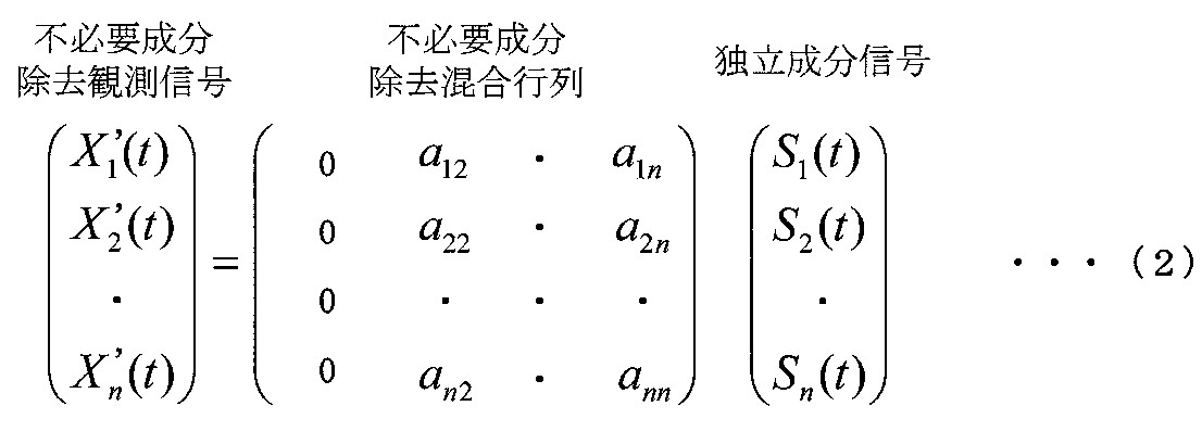
- the unnecessary component removal observation signal creation unit accumulates the N ⁇ N unnecessary component removal mixing matrix and the N independent component signals S n (t) as shown in the following equation (2).
- N unnecessary component removal observation signals X n ′ (t) are created.
- an observation signal X n (t) unnecessary component removal observation signal to remove a signal corresponding to the unwanted components from the X n '(t) Can do.
- the predetermined frequency band is at least selected from the group consisting of a frequency band indicating skin blood flow, a frequency band indicating heart rate variability, and a frequency band indicating pulsation / respiration.
- a single frequency band may be used.
- the analysis method of the present invention includes a plurality of light transmitting / receiving probes disposed on the skin surface of the subject, a plurality of light receiving probes disposed on the skin surface, and the light transmitting probe. Irradiates light on the skin surface and controls the light receiving probe to detect light emitted from the skin surface, thereby acquiring an observation signal indicating a change with time of the measurement site in the subject.
- FIG. 1 It is a block diagram which shows the structure of the optical biological measurement apparatus which is one Embodiment of this invention. It is a top view which shows the positional relationship of 16 light transmission probes in a holder, and 16 light reception probes. It is a figure which shows the monitor screen displayed by the photobiological measuring device which concerns on this invention. It is a figure which shows the monitor screen displayed by the photobiological measuring device which concerns on this invention. It is a figure which shows the monitor screen displayed by the photobiological measuring device which concerns on this invention.
- FIG. 1 is a block diagram showing a configuration of an optical biological measurement apparatus according to an embodiment of the present invention.
- FIG. 2 is a plan view showing the positional relationship between the 16 light transmitting probes and the 16 light receiving probes in the holder (transmission / reception unit).
- 3 to 5 are diagrams showing monitor screens displayed by the optical biological measurement apparatus according to the present invention.
- FIG. 3 is a monitor screen on which 52 observation signals X n (t) are displayed by the optical biological measurement device
- FIG. 4 is a diagram showing 52 independent component signals S n (t) converted by the optical biological measurement device.
- FIG. 5 is a monitored by optical biometric device 52 amino unwanted component removal observation signals X n '(t) is the display screen .
- the optical biological measurement apparatus 1 includes a holder 11, a light emitting unit 2, a light detection unit 3, and a control unit (computer) 20 that controls the entire optical biological measurement apparatus 1.
- the holder 11 has 16 light transmitting probes 12 and 16 light receiving probes 13, and the light transmitting probes 12 and the light receiving probes 13 are alternately arranged in the vertical direction and the horizontal direction. It is arranged like this. Note that the distance between the light transmitting probe 12 and the light receiving probe 13 is 30 mm.
- the 16 light transmitting probes 12 emit light, while the 16 light receiving probes 13 detect light quantity (light detection signals).
- the light emitting unit 2 transmits light to one light transmitting probe 12 selected from among the 16 light transmitting probes 12 by a drive signal input from the computer 20.
- Near-infrared light (for example, 780 nm and 850 nm) is used as the light.
- the light detection unit 3 outputs 16 light detection signals to the computer 20 by individually detecting near-infrared light (for example, 780 nm and 850 nm) received by the 16 light receiving probes 13.
- the computer 20 includes a CPU 21, and further includes a memory 25, a display device 23 having a monitor screen 23 a and the like, and a keyboard 22 a and a mouse 22 b that are input devices 22. Further, the functions processed by the CPU 21 will be described as a block.
- the transmitter / receiver control unit 4 that acquires the observation signal X n (t) by controlling the light emitting unit 2 and the light detection unit 3, and unnecessary component removal observation And an arithmetic unit 5 that generates a signal X n ′ (t).
- the calculation unit 5 includes a mixing matrix creation unit 51, a power spectrum calculation unit 52, an unnecessary component signal determination unit 53, an unnecessary component removal mixed matrix creation unit 54, and an unnecessary component removal observation signal creation unit 55.
- the memory 25 includes a light detection signal storage area 61 for storing a light detection signal, and a threshold storage area 62 for storing a predetermined frequency band ⁇ 1 and a threshold T.
- the light transmission / reception unit control unit 4 stores a light detection signal in the light detection signal storage area 61 when a light emission control unit 42 that outputs a drive signal to the light emission unit 2 and a light detection signal from the light detection unit 3 are input.
- an observation signal creating unit 44 that creates an observation signal X n (t) indicating a change with time in the oxygenated hemoglobin concentration.
- the light emission control unit 42 performs control to output a drive signal for transmitting light to the light transmission probe 12 to the light emitting unit 2.
- the photodetection control unit 43 is configured to store the 16 photodetection signals detected from the 16 light receiving probes 13 in the photodetection signal storage area 61 when the photodetection signal from the photodetection unit 3 is input. I do. That is, every time light is transmitted from one light transmission probe 12, 16 light detection signals are stored in the light detection signal storage area 61.
- the observation signal creation unit 44 acquires 52 light detection signals to the light receiving probe 13 adjacent to the light transmission probe 12 in the light detection signal stored in the light detection signal storage area 61, and acquires the acquired 52 pieces of light detection signals. Based on the light detection signal, control is performed to create an observation signal X n (t) indicating a change with time in the oxygenated hemoglobin concentration. That is, since the light detection signal of the light to the light receiving probe 13 adjacent to the light transmitting probe 12 is the light detection signal obtained from the measurement parts # 1 to # 52 of the brain, light is transmitted from all the light transmitting probes 12. After being illuminated, 52 photodetection signals selected from 256 photodetection signals are obtained.
- the mixing matrix creating unit 51 generates 52 observation signals X n (t) by independent component analysis, 52 ⁇ 52 mixing matrices, and 52 independent component signals S n (t ) Is separated into products (mixing matrix creation step).
- the power spectrum calculation unit 52 performs Fourier transform on 52 independent component signals S n (t) that are functions of 52 times and intensities, thereby converting independent component signals S n that are functions of 52 frequencies and intensities.
- control is performed to calculate the power spectrum of the predetermined frequency band ⁇ 1 in each conversion independent component signal S n ( ⁇ ).
- 52 (# 1 to # 52) independent component signals S n (t) and converted independent component signals S n ( ⁇ ) as shown in FIG. 4 are obtained.
- the unnecessary component signal determination unit 53 compares the power spectrum of the predetermined frequency band ⁇ 1 in each converted independent component signal S n ( ⁇ ) with the threshold value T, so that 52 independent component signals S n (t ), An independent component signal S n (t) corresponding to the unnecessary component is controlled (unnecessary component signal determining step). For example, when the power spectrum S 1 ( ⁇ 1 ) is greater than or equal to the threshold T, the independent component signal S 1 (t) is determined to be a signal corresponding to an unnecessary component, while the power spectrum S 1 ( ⁇ 1). ) Is less than the threshold T, it is determined that the independent component signal S 1 (t) is a signal based on blood flow accompanying brain activation.
- the independent component signal S 2 (t) is determined to be a signal corresponding to an unnecessary component, while the power spectrum S 2 ( ⁇ 2). ) Is less than the threshold T, it is determined that the independent component signal S 2 (t) is a signal based on blood flow accompanying brain activation. In this way, the independent component signal S n (t) corresponding to the unnecessary component is found out of the 52 independent component signals S n (t).
- the unnecessary component removal mixing matrix creation unit 54 corresponds to the unnecessary component in the mixing matrix based on the independent component signal S n (t) corresponding to the unnecessary component found by the unnecessary component signal determination unit 53. Control is performed to create an unnecessary component elimination mixing matrix in which 0 is substituted into the column vector. For example, when the power spectrum S 1 ( ⁇ 1 ) is greater than or equal to the threshold T, an unnecessary component removal mixing matrix is created by substituting 0 for the first column vector. Further, when the power spectrum S 2 ( ⁇ 1 ) is equal to or greater than the threshold T, an unnecessary component removal mixing matrix in which 0 is substituted into the second column vector is created. In this way, an unnecessary component removal mixing matrix is created.
- the unnecessary component removal observation signal creation unit 55 integrates the unnecessary component removal mixing matrix and the 52 independent component signals S n (t) as shown in the equation (2), thereby obtaining 52 unnecessary components. Control for creating the necessary component removal observation signal X n ′ (t) is performed. As a result, 52 (# 1 to # 52) unnecessary component removal observation signals X n ′ (t) as shown in FIG. 5 are obtained.
- an observer such as a doctor can easily diagnose whether or not a medical condition such as cerebral ischemia has occurred by observing the unnecessary component removal observation signal X n ′ (t).
- the holder 11 having 16 light transmitting probes 12 and 16 light receiving probes 13 is shown.
- different numbers for example, 12 light transmitting probes and 12 light receiving probes, It is good also as a holder which has.
- the present invention is used as a non-invasive optical brain functional imaging device that measures the activity state of a brain measurement site using near-infrared light, an oxygen monitor that monitors the oxygen consumption of a measurement site in a living body, and the like. be able to.
- Optical biological measurement device 4 Transmitter / receiver control unit 5: Calculation unit 11: Holder (transmitter / receiver) 12: Light transmitting probe 13: Light receiving probe 22: Input device 23: Display device 51: Mixing matrix creation unit 52: Power spectrum calculation unit 53: Unnecessary component signal determination unit
Landscapes
- Health & Medical Sciences (AREA)
- Life Sciences & Earth Sciences (AREA)
- Physics & Mathematics (AREA)
- Engineering & Computer Science (AREA)
- Animal Behavior & Ethology (AREA)
- General Health & Medical Sciences (AREA)
- Biophysics (AREA)
- Pathology (AREA)
- Veterinary Medicine (AREA)
- Biomedical Technology (AREA)
- Heart & Thoracic Surgery (AREA)
- Medical Informatics (AREA)
- Molecular Biology (AREA)
- Surgery (AREA)
- Public Health (AREA)
- Nuclear Medicine, Radiotherapy & Molecular Imaging (AREA)
- Neurology (AREA)
- Radiology & Medical Imaging (AREA)
- Mathematical Physics (AREA)
- Artificial Intelligence (AREA)
- Computer Vision & Pattern Recognition (AREA)
- Physiology (AREA)
- Psychiatry (AREA)
- Signal Processing (AREA)
- Optics & Photonics (AREA)
- Spectroscopy & Molecular Physics (AREA)
- Measurement Of The Respiration, Hearing Ability, Form, And Blood Characteristics Of Living Organisms (AREA)
- Investigating Or Analysing Materials By Optical Means (AREA)
Abstract
Description
そこで、医師等の観察者は、脳虚血等の病状が生じているか否かを容易に診察することができるように、観測信号Xn(t)において脳賦活に伴う血流に基づく信号と、それ以外の信号とを峻別することを視覚的評価で行っている。例えば、タスクに同期している信号のみを脳賦活信号として扱ったり、脳内の生理学的変化と考えにくい信号をアーチファクトとして処理したりする。さらに、ランダムノイズに関しては、測定の繰返し回数を多くし、積算処理によって除去している。
また、脳虚血等の病状が生じているか否かを容易に診察する他の方法として、観測信号Xn(t)を一次線形モデル(GLM)で統計解析して、基準観測信号と比較することにより、基準観測信号と観測信号Xn(t)との類似性、及び、統計的有意性の評価量(P値)を統計結果として算出するようにしている(例えば、特許文献2参照)。
また、上述したような統計解析では、観測信号Xn(t)について類似性及び評価量(P値)がわかるが、観測信号Xn(t)には脳賦活に伴う血流に基づく信号の他、皮膚血流や心拍変動や脈動・呼吸等の変化に基づく信号も重畳されたままであるので、脳虚血等の病状が生じているか否かを正確に診察することができないことがあった。
そこで、本発明は、観測信号から不必要成分に対応する信号を除去することができる光生体計測装置及び解析方法を提供することを目的とする。
また、「不必要成分に対応する信号」とは、脳賦活に伴う血流に基づく信号以外の信号のことをいい、例えば、皮膚血流に基づく信号や、心拍変動に基づく信号や、脈動・呼吸に基づく信号等のことをいう。
さらに、「所定の周波数帯域」とは、予め設定される任意の周波数帯域のことをいい、例えば、「所定の周波数帯域」として、皮膚血流を示す周波数帯域(0.03~0.15Hz)や、心拍変動を示す周波数帯域(0.15~0.5Hz)や、脈動・呼吸を示す周波数帯域(0.8~2.0Hz)等が設定されることになる。
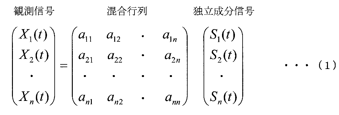
一般に皮膚血流に基づく信号は、所定の周波数帯域λ1に現れることがわかっている。よって、N個の独立成分信号Sn(t)の内から、不必要成分に対応する独立成分信号Sn(t)を見つけ出すために、パワースペクトル算出部は、N個の独立成分信号Sn(t)をフーリエ変換することで、N個の変換独立成分信号Sn(λ)を作成する。そして、N個の変換独立成分信号Sn(λ)における所定の周波数帯域λ1のパワースペクトルSn(λ1)を算出する。
次に、不必要成分信号決定部は、N個のパワースペクトルSn(λ1)と閾値Tとをそれぞれ比較することで、N個の独立成分信号Sn(t)の内から、不必要成分に対応する独立成分信号Sn(t)を見つけ出す。例えば、パワースペクトルS1(λ1)が閾値T以上であるときには、独立成分信号S1(t)を、不必要成分に対応する信号であると判定し、一方、パワースペクトルS1(λ1)が閾値T未満であるときには、独立成分信号S1(t)を、脳賦活に伴う血流に基づく信号であると判定する。なお、不必要成分に対応する信号であると判定する数は、1つに限らず、複数になることもありうる。
また、本発明の光生体計測装置は、前記演算部は、前記不必要成分信号決定部で見つけ出された不必要成分に対応する独立成分信号に基づいて、前記混合行列における不必要成分に対応する列ベクトルに0を代入した不必要成分除去混合行列を作成する不必要成分除去混合行列作成部と、不必要成分除去混合行列と、複数の独立成分信号とを積算することにより、複数の不必要成分除去観測信号を作成する不必要成分除去観測信号作成部とを備えるようにしてもよい。
次に、不必要成分除去観測信号作成部は、下記式(2)で示すように、N×Nの不必要成分除去混合行列と、N個の独立成分信号Sn(t)とを積算することにより、N個の不必要成分除去観測信号Xn'(t)を作成する。
そして、本発明の解析方法は、被検体の皮膚表面上に配置される複数の送光プローブと、当該皮膚表面上に配置される複数の受光プローブとを有する送受光部と、前記送光プローブが皮膚表面に光を照射するとともに、前記受光プローブが皮膚表面から放出される光を検出するように制御することで、前記被検体中の測定部位に関する経時変化を示す観測信号を取得する送受光部制御部とを備える光生体計測装置を用いて、前記観測信号から、不必要成分に対応する信号を除去することにより、不必要成分除去観測信号を作成する解析方法であって、独立成分分析によって複数の観測信号を、混合行列と、複数の独立成分信号との積に分離する混合行列作成工程と、各変換独立成分信号における所定の周波数帯域のパワースペクトルと閾値とをそれぞれ比較することで、複数の独立成分信号の内から、不必要成分に対応する独立成分信号を見つけ出す不必要成分信号決定工程と含むようにしている。
さらに、図3~図5は、本発明に係る光生体計測装置により表示されたモニタ画面を示す図である。図3は、光生体計測装置により52個の観測信号Xn(t)が表示されたモニタ画面であり、図4は、光生体計測装置により52個の独立成分信号Sn(t)と変換独立成分信号Sn(λ)とが表示されたモニタ画面であり、図5は、光生体計測装置により52個の不必要成分除去観測信号Xn'(t)が表示されたモニタ画面である。
ホルダ11は、図2に示すように、16個の送光プローブ12と16個の受光プローブ13とを有し、送光プローブ12と受光プローブ13とが縦方向と横方向とに交互となるように配置されたものである。なお、送光プローブ12と受光プローブ13との間の距離は、30mmである。また、16個の送光プローブ12は、光を出射するものであり、一方、16個の受光プローブ13は、光量(光検出信号)を検出するものである。
発光部2は、コンピュータ20から入力された駆動信号により16個の送光プローブ12の内から選択される1個の送光プローブ12に光を送光する。上記光としては、近赤外光(例えば、780nmと850nm)が用いられる。
光検出部3は、16個の受光プローブ13で受光した近赤外光(例えば、780nmと850nm)を個別に検出することにより、16個の光検出信号をコンピュータ20に出力する。
また、CPU21が処理する機能をブロック化して説明すると、発光部2及び光検出部3を制御することで観測信号Xn(t)を取得する送受光部制御部4と、不必要成分除去観測信号Xn'(t)を作成する演算部5とを備える。さらに、演算部5は、混合行列作成部51と、パワースペクトル算出部52と、不必要成分信号決定部53と、不必要成分除去混合行列作成部54と、不必要成分除去観測信号作成部55とを有する。
さらに、メモリ25は、光検出信号を記憶する光検出信号記憶領域61と、所定の周波数帯域λ1と閾値Tとを記憶する閾値記憶領域62とを有する。
発光制御部42は、送光プローブ12に光を送光する駆動信号を発光部2に出力する制御を行う。
光検出制御部43は、光検出部3からの光検出信号が入力されることにより、16個の受光プローブ13から検出された16個の光検出信号を光検出信号記憶領域61に記憶させる制御を行う。つまり、1個の送光プローブ12から光が送光されるごとに、16個の光検出信号が光検出信号記憶領域61に記憶されることになる。
つまり、送光プローブ12と隣接した受光プローブ13への光の光検出信号を、脳の測定部位#1~#52から得られる光検出信号とするので、全ての送光プローブ12から光が送光された後に、256個の光検出信号から選択される52個の光検出信号を得る。そして、このようにして得られた52個の光検出信号に基づいて、52箇所の脳表部位(#1~#52)におけるオキシヘモグロビン濃度(観測信号)Xn(t)(n=1、2、・・・、52)を求める。これにより、図3に示すような52個(#1~#52)の観測信号Xn(t)が得られる。
パワースペクトル算出部52は、52個の時間と強度との関数である独立成分信号Sn(t)をフーリエ変換することで、52個の周波数と強度との関数である変換独立成分信号Sn(λ)を作成することにより、各変換独立成分信号Sn(λ)における所定の周波数帯域λ1のパワースペクトルをそれぞれ算出する制御を行う。これにより、図4に示すような52個(#1~#52)の独立成分信号Sn(t)と変換独立成分信号Sn(λ)とが得られる。
不必要成分除去観測信号作成部55は、式(2)で示すように、不必要成分除去混合行列と、52個の独立成分信号Sn(t)とを積算することにより、52個の不必要成分除去観測信号Xn'(t)を作成する制御を行う。これにより、図5に示すような52個(#1~#52)の不必要成分除去観測信号Xn'(t)が得られる。
上述した光生体計測装置1では、16個の送光プローブ12と16個の受光プローブ13とを有するホルダ11を示したが、異なる数、例えば12個の送光プローブと12個の受光プローブとを有するホルダとしてもよい。
4:送受光部制御部
5:演算部
11:ホルダ(送受光部)
12:送光プローブ
13:受光プローブ
22:入力装置
23:表示装置
51:混合行列作成部
52:パワースペクトル算出部
53:不必要成分信号決定部
Claims (4)
- 被検体の皮膚表面上に配置される複数の送光プローブと、当該皮膚表面上に配置される複数の受光プローブとを有する送受光部と、
前記送光プローブが皮膚表面に光を照射するとともに、前記受光プローブが皮膚表面から放出される光を検出するように制御することで、前記被検体中の測定部位に関する経時変化を示す観測信号を取得する送受光部制御部と、
前記観測信号から、不必要成分に対応する信号を除去することにより、不必要成分除去観測信号を作成する演算部とを備える光生体計測装置であって、
前記演算部は、独立成分分析によって複数の観測信号を、混合行列と、複数の独立成分信号との積に分離する混合行列作成部と、
時間と強度との関数である複数の独立成分信号をフーリエ変換することで、周波数と強度との関数である複数の変換独立成分信号を作成することにより、各変換独立成分信号における所定の周波数帯域のパワースペクトルをそれぞれ算出するパワースペクトル算出部と、
各変換独立成分信号における所定の周波数帯域のパワースペクトルと閾値とをそれぞれ比較することで、複数の独立成分信号の内から、不必要成分に対応する独立成分信号を見つけ出す不必要成分信号決定部とを備えることを特徴とする光生体計測装置。 - 前記演算部は、前記不必要成分信号決定部で見つけ出された不必要成分に対応する独立成分信号に基づいて、前記混合行列における不必要成分に対応する列ベクトルに0を代入した不必要成分除去混合行列を作成する不必要成分除去混合行列作成部と、
不必要成分除去混合行列と、複数の独立成分信号とを積算することにより、複数の不必要成分除去観測信号を作成する不必要成分除去観測信号作成部とを備えることを特徴とする請求項1に記載の光生体計測装置。 - 前記所定の周波数帯域は、皮膚血流を示す周波数帯域、心拍変動を示す周波数帯域、及び、脈動・呼吸を示す周波数帯域からなる群から選択される少なくとも1つの周波数帯域であることを特徴とする請求項1又は請求項2に記載の光生体計測装置。
- 被検体の皮膚表面上に配置される複数の送光プローブと、当該皮膚表面上に配置される複数の受光プローブとを有する送受光部と、
前記送光プローブが皮膚表面に光を照射するとともに、前記受光プローブが皮膚表面から放出される光を検出するように制御することで、前記被検体中の測定部位に関する経時変化を示す観測信号を取得する送受光部制御部とを備える光生体計測装置を用いて、前記観測信号から、不必要成分に対応する信号を除去することにより、不必要成分除去観測信号を作成する解析方法であって、
独立成分分析によって複数の観測信号を、混合行列と、複数の独立成分信号との積に分離する混合行列作成工程と、
各変換独立成分信号における所定の周波数帯域のパワースペクトルと閾値とをそれぞれ比較することで、複数の独立成分信号の内から、不必要成分に対応する独立成分信号を見つけ出す不必要成分信号決定工程と含むことを特徴とする解析方法。
Priority Applications (3)
| Application Number | Priority Date | Filing Date | Title |
|---|---|---|---|
| JP2011504767A JP5370475B2 (ja) | 2009-03-19 | 2010-01-12 | 光生体計測装置及び解析方法 |
| CN2010800094494A CN102333489A (zh) | 2009-03-19 | 2010-01-12 | 光学生物体测量装置以及分析方法 |
| US13/256,287 US20120010484A1 (en) | 2009-03-19 | 2010-01-12 | Photobiological measuring device and analyzing method |
Applications Claiming Priority (2)
| Application Number | Priority Date | Filing Date | Title |
|---|---|---|---|
| JP2009-068351 | 2009-03-19 | ||
| JP2009068351 | 2009-03-19 |
Publications (1)
| Publication Number | Publication Date |
|---|---|
| WO2010106826A1 true WO2010106826A1 (ja) | 2010-09-23 |
Family
ID=42739493
Family Applications (1)
| Application Number | Title | Priority Date | Filing Date |
|---|---|---|---|
| PCT/JP2010/050205 Ceased WO2010106826A1 (ja) | 2009-03-19 | 2010-01-12 | 光生体計測装置及び解析方法 |
Country Status (4)
| Country | Link |
|---|---|
| US (1) | US20120010484A1 (ja) |
| JP (1) | JP5370475B2 (ja) |
| CN (1) | CN102333489A (ja) |
| WO (1) | WO2010106826A1 (ja) |
Cited By (2)
| Publication number | Priority date | Publication date | Assignee | Title |
|---|---|---|---|---|
| JP2012239668A (ja) * | 2011-05-20 | 2012-12-10 | National Institute Of Advanced Industrial Science & Technology | 生体光計測装置、プログラム及び生体光計測方法 |
| CN103135772A (zh) * | 2011-11-29 | 2013-06-05 | 原相科技股份有限公司 | 键盘模块及显示系统 |
Families Citing this family (5)
| Publication number | Priority date | Publication date | Assignee | Title |
|---|---|---|---|---|
| CN107126190B (zh) * | 2012-04-25 | 2020-05-22 | 株式会社岛津制作所 | 光生物测量装置 |
| CN104284629B (zh) * | 2012-05-11 | 2016-04-20 | 株式会社岛津制作所 | 光生物体测量系统及其使用方法 |
| WO2014016963A1 (ja) * | 2012-07-27 | 2014-01-30 | 株式会社島津製作所 | 光生体計測装置及びそれを用いた解析方法 |
| CN104780847B (zh) * | 2012-11-14 | 2017-06-23 | 株式会社岛津制作所 | 光生物体测量装置以及用于该光生物体测量装置的位置测量装置 |
| US12193814B2 (en) * | 2018-09-12 | 2025-01-14 | Children's Medical Center Corporation | Ongoing pain detection system and method for utilizing near-infrared spectroscopy |
Citations (6)
| Publication number | Priority date | Publication date | Assignee | Title |
|---|---|---|---|---|
| JP2005143609A (ja) * | 2003-11-12 | 2005-06-09 | Hitachi Medical Corp | 光計測装置 |
| JP2005245636A (ja) * | 2004-03-02 | 2005-09-15 | Shimadzu Corp | 近赤外光による生体光計測方法及び装置 |
| JP2006280421A (ja) * | 2005-03-31 | 2006-10-19 | Shimadzu Corp | 脳機能情報モニタリング装置 |
| JP2007044104A (ja) * | 2005-08-08 | 2007-02-22 | Shimadzu Corp | 信号解析装置および信号解析方法 |
| JP2007289224A (ja) * | 2006-04-21 | 2007-11-08 | Hitachi Ltd | 生体計測装置および生体計測方法 |
| JP2008148797A (ja) * | 2006-12-15 | 2008-07-03 | Hitachi Ltd | 生体光計測装置 |
Family Cites Families (2)
| Publication number | Priority date | Publication date | Assignee | Title |
|---|---|---|---|---|
| US6240309B1 (en) * | 1995-10-06 | 2001-05-29 | Hitachi, Ltd. | Optical measurement instrument for living body |
| CN100348152C (zh) * | 2005-11-29 | 2007-11-14 | 东南大学 | 基于独立成份空间相关性消除功能磁共振数据噪声的方法 |
-
2010
- 2010-01-12 CN CN2010800094494A patent/CN102333489A/zh active Pending
- 2010-01-12 JP JP2011504767A patent/JP5370475B2/ja active Active
- 2010-01-12 WO PCT/JP2010/050205 patent/WO2010106826A1/ja not_active Ceased
- 2010-01-12 US US13/256,287 patent/US20120010484A1/en not_active Abandoned
Patent Citations (6)
| Publication number | Priority date | Publication date | Assignee | Title |
|---|---|---|---|---|
| JP2005143609A (ja) * | 2003-11-12 | 2005-06-09 | Hitachi Medical Corp | 光計測装置 |
| JP2005245636A (ja) * | 2004-03-02 | 2005-09-15 | Shimadzu Corp | 近赤外光による生体光計測方法及び装置 |
| JP2006280421A (ja) * | 2005-03-31 | 2006-10-19 | Shimadzu Corp | 脳機能情報モニタリング装置 |
| JP2007044104A (ja) * | 2005-08-08 | 2007-02-22 | Shimadzu Corp | 信号解析装置および信号解析方法 |
| JP2007289224A (ja) * | 2006-04-21 | 2007-11-08 | Hitachi Ltd | 生体計測装置および生体計測方法 |
| JP2008148797A (ja) * | 2006-12-15 | 2008-07-03 | Hitachi Ltd | 生体光計測装置 |
Cited By (3)
| Publication number | Priority date | Publication date | Assignee | Title |
|---|---|---|---|---|
| JP2012239668A (ja) * | 2011-05-20 | 2012-12-10 | National Institute Of Advanced Industrial Science & Technology | 生体光計測装置、プログラム及び生体光計測方法 |
| CN103135772A (zh) * | 2011-11-29 | 2013-06-05 | 原相科技股份有限公司 | 键盘模块及显示系统 |
| CN103135772B (zh) * | 2011-11-29 | 2016-06-01 | 原相科技股份有限公司 | 键盘模块及显示系统 |
Also Published As
| Publication number | Publication date |
|---|---|
| JP5370475B2 (ja) | 2013-12-18 |
| CN102333489A (zh) | 2012-01-25 |
| US20120010484A1 (en) | 2012-01-12 |
| JPWO2010106826A1 (ja) | 2012-09-20 |
Similar Documents
| Publication | Publication Date | Title |
|---|---|---|
| US12226208B2 (en) | Systems , devices, and methods for performing trans-abdominal fetal oximetry and/or trans-abdominal fetal pulse oximetry using diffuse optical tomography | |
| JP5896025B2 (ja) | 光生体計測装置及びそれを用いた解析方法 | |
| JP5370475B2 (ja) | 光生体計測装置及び解析方法 | |
| JP5324999B2 (ja) | 生体光計測装置及び生体光計測方法 | |
| US20120277559A1 (en) | Apparatus for Measuring Blood Parameters | |
| US20110082355A1 (en) | Photoplethysmography device and method | |
| EP2591732A1 (en) | Biological photometric device and biological photometry method using same | |
| JP3928051B2 (ja) | 心理状態評価装置 | |
| JP2009095380A (ja) | 光生体計測装置 | |
| JP4470681B2 (ja) | 光生体計測装置 | |
| JP5248758B2 (ja) | 光計測装置 | |
| JP5679629B2 (ja) | 光脳機能計測装置 | |
| JP6412956B2 (ja) | 生体光計測装置、解析装置、及び方法 | |
| JPWO2015004789A1 (ja) | 生体光計測データ解析装置、解析方法およびそのためのプログラム | |
| Premchand et al. | Synchronizing Motor Imagery Cue in fNIRS Brain-Computer Interface to reduce confounding effects of respiration | |
| JP2009082595A (ja) | 光生体測定装置 | |
| Lapitan et al. | Estimation of the Signal-to-Noise Ratio in Incoherent Optical Fluctuation Flowmetry | |
| Bachir | Molecular and Biomolecular Spectroscopy | |
| JP4946847B2 (ja) | 光脳機能イメージング装置 | |
| Fernandez et al. | Instrument for Early Detection of Hemorrhage via Diffuse Correlation Spectroscopy | |
| Halim et al. | Utilization of functional near infrared spectroscopy for non-invasive evaluation | |
| Vazquez-Jaccaud et al. | Cross-talk analysis in arterial hemoglobin oxygen saturation measurements | |
| Le Giang et al. | Evaluation of Hemodynamic Responses to Visual Tasks Using Functional Near Infrared Spectroscopy | |
| Kek et al. | Real-time imaging of muscle oxygenation using spatially resolved near-infrared spectroscopy | |
| Franceschini et al. | Real-time video of brain activation in human subjects using a non-invasive near-infrared technique |
Legal Events
| Date | Code | Title | Description |
|---|---|---|---|
| WWE | Wipo information: entry into national phase |
Ref document number: 201080009449.4 Country of ref document: CN |
|
| 121 | Ep: the epo has been informed by wipo that ep was designated in this application |
Ref document number: 10753321 Country of ref document: EP Kind code of ref document: A1 |
|
| ENP | Entry into the national phase |
Ref document number: 2011504767 Country of ref document: JP Kind code of ref document: A |
|
| WWE | Wipo information: entry into national phase |
Ref document number: 13256287 Country of ref document: US |
|
| NENP | Non-entry into the national phase |
Ref country code: DE |
|
| 122 | Ep: pct application non-entry in european phase |
Ref document number: 10753321 Country of ref document: EP Kind code of ref document: A1 |