WO2010106628A1 - 中継局の配置方法および中継局配置装置 - Google Patents
中継局の配置方法および中継局配置装置 Download PDFInfo
- Publication number
- WO2010106628A1 WO2010106628A1 PCT/JP2009/055087 JP2009055087W WO2010106628A1 WO 2010106628 A1 WO2010106628 A1 WO 2010106628A1 JP 2009055087 W JP2009055087 W JP 2009055087W WO 2010106628 A1 WO2010106628 A1 WO 2010106628A1
- Authority
- WO
- WIPO (PCT)
- Prior art keywords
- transmission
- optical signal
- relay station
- sections
- relay
- Prior art date
- Legal status (The legal status is an assumption and is not a legal conclusion. Google has not performed a legal analysis and makes no representation as to the accuracy of the status listed.)
- Ceased
Links
Images



Classifications
-
- H—ELECTRICITY
- H04—ELECTRIC COMMUNICATION TECHNIQUE
- H04B—TRANSMISSION
- H04B10/00—Transmission systems employing electromagnetic waves other than radio-waves, e.g. infrared, visible or ultraviolet light, or employing corpuscular radiation, e.g. quantum communication
- H04B10/29—Repeaters
- H04B10/291—Repeaters in which processing or amplification is carried out without conversion of the main signal from optical form
-
- H—ELECTRICITY
- H04—ELECTRIC COMMUNICATION TECHNIQUE
- H04J—MULTIPLEX COMMUNICATION
- H04J14/00—Optical multiplex systems
- H04J14/02—Wavelength-division multiplex systems
- H04J14/0227—Operation, administration, maintenance or provisioning [OAMP] of WDM networks, e.g. media access, routing or wavelength allocation
- H04J14/0254—Optical medium access
- H04J14/0256—Optical medium access at the optical channel layer
- H04J14/026—Optical medium access at the optical channel layer using WDM channels of different transmission rates
-
- H—ELECTRICITY
- H04—ELECTRIC COMMUNICATION TECHNIQUE
- H04J—MULTIPLEX COMMUNICATION
- H04J14/00—Optical multiplex systems
- H04J14/02—Wavelength-division multiplex systems
- H04J14/0201—Add-and-drop multiplexing
- H04J14/0202—Arrangements therefor
Definitions
- the present invention relates to a relay station arrangement method and a relay station arrangement apparatus, and more particularly, to a relay station arrangement method and a relay station arrangement apparatus in a transmission system that transmits optical signals having different transmission rates.
- a WDM Widelength Division Modulation
- NRZ NonNReturn Zero
- phase modulation schemes such as QPSK (Quadrature Phase Shift Key) modulation scheme and DQPSK (Differential Quadrature Phase Shift Key) modulation scheme are being studied in 40 Gbps and 100 Gbps optical transmission systems.
- the optical transmission system consists of multiple relay stations.
- a regenerative relay station capable of reproducing an optical signal.
- Patent Document 1 describes a method of arranging a regenerative repeater station in an optical transmission system having a plurality of repeater stations.
- the optical transmission system transmits optical signals having different transmission speeds such as an optical signal of 10 Gbps and an optical signal of 40 Gbps. In such a case, it is required to appropriately arrange the regenerative relay station.
- This relay station arrangement method and relay station arrangement apparatus have been made in view of the above problems, and an object thereof is to appropriately arrange regenerative relay stations.
- the relay station arrangement method is a relay station arrangement method in an optical transmission system including a plurality of relay stations arranged to transmit an optical signal having a first transmission rate from a transmission end to a reception end, For an optical signal having a second transmission rate different from the first transmission rate for a section connecting any two relay stations in which a regenerative relay station capable of reproducing an optical signal among the plurality of relay stations is connected. Determining whether transmission is possible, determining a combination of sections determined to be transmission that constitutes transmission of an optical signal from the transmission end to the reception end, and both ends of each section of the determined combination, The step of determining whether or not transmission is possible is determined in a section including a plurality of the sections, but is not satisfied in any of the plurality of sections. Including conditions
- the relay station arrangement apparatus performs relay station arrangement in an optical transmission system including a plurality of relay stations arranged to transmit an optical signal having a first transmission rate from a transmission end to a reception end. A second transmission that is different from the first transmission rate for a section connecting any two relay stations in which a regenerative relay station capable of reproducing an optical signal among the plurality of relay stations is connected.
- a determination unit that determines whether or not transmission is possible for a speed optical signal, and a determination unit that determines a combination of sections determined to be transmission that constitutes transmission of the optical signal from the transmission end to the reception end.
- An arrangement unit that sets both ends of each section of the combination as a relay station where a regenerative relay station is to be arranged, and the determination unit is established in a section that includes a plurality of the sections. It includes judgment conditions that are not satisfied.
- the regenerative relay station can be appropriately arranged.
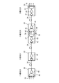
- FIG. 1A is a diagram illustrating an optical transmission network using the relay station arrangement method
- FIG. 1B is a diagram in which the optical transmission network of FIG. 1A is divided into partial sections.
- FIG. 2 is a diagram illustrating each relay station.
- FIG. 3A and FIG. 3B are diagrams illustrating an optical transmission system that transmits an optical signal from a transmission end to a reception end.
- FIG. 4A to FIG. 4D are diagrams illustrating an optical transmission system that transmits an optical signal from a transmission end to a reception end.
- 5 (a) and 5 (b) are diagrams showing dispersion characteristics with respect to the transmission distances of FIGS. 4 (c) and 4 (d), respectively.
- FIG. 6 is a block diagram of the relay station arrangement apparatus.
- FIG. 6 is a block diagram of the relay station arrangement apparatus.
- FIG. 7 is a flowchart illustrating a method for arranging a certain relay station.
- FIG. 8 is a flowchart illustrating an example of step S10 in FIG.
- FIG. 9 is a flowchart illustrating an example of step S12 in FIG.
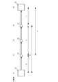
- FIG. 10 is a diagram showing an example in which regenerative relay stations are arranged according to the flow of FIG.
- FIG. 1A is a diagram illustrating an example of a network in which a transmission system in which the relay station is arranged is used.
- a WDM system is used, and optical signals having different transmission speeds (for example, optical signals of 10 Gbps and 40 Gbps) are transmitted.
- the network 60 has three ring-shaped partial sections 61 to 63 joined together.
- Each of the partial sections 61 to 63 includes a transmission path 74 such as an optical fiber connecting the relay stations 70 and 72 and the relay stations 70 and 72.
- the relay station 72 is a relay station that receives optical signals from a plurality of transmission paths 74 or outputs optical signals to the plurality of transmission paths 74, and is, for example, an optical HUB.
- the relay station 70 is a relay station that receives an optical signal from one transmission path 74 and outputs the optical signal to one transmission path 74.
- the relay station 70 is an OADM (Optical) add / drop Multiplexer), ILA (In Line Amplifier). Or it is a bypass.
- OADM Optical
- ILA In Line Amplifier
- the network 60 is divided into, for example, partial sections 61 to 63 as shown in FIG.
- a relay station is selected so that a desired optical signal can be transmitted. Thereafter, it is evaluated whether or not a desired optical signal can be transmitted between relay stations straddling each of the partial sections 61 to 63. In this way, each relay station is selected.
- the network is divided into ring-shaped partial sections 61 to 63, but may be divided into linear partial sections.
- FIG. 2 is a diagram for explaining each relay station.
- the relay stations 26 to 28 are connected by a transmission line 34 such as an optical fiber.
- Relay stations 26, 28 and 29 are OADMs 30 and relay station 27 is an ILA 32.
- the ILA 32 is a relay station that performs amplification of an optical signal and control of chromatic dispersion.
- the ILA 32 includes, for example, an amplifier 40 and a DCM (Dispersion Compensation Module) 42.
- the amplifier 40 is, for example, an EDFA (Erbium-doped Fiber Amplifier), and amplifies the optical signal.
- the DCM 42 compensates for chromatic dispersion. By providing the desired amplifier 40 and DCM 42 in the ILA 32, desired gain and dispersion characteristics can be obtained.
- the OADM 30 performs amplification of the optical signal and control of chromatic dispersion, and once demultiplexes the optical signal in which the optical signals of a plurality of wavelengths are combined, and combines them again.
- the OADM 30 includes, for example, an amplifier 40, a DCM 42, a duplexer 44, a multiplexer 46, and a REG (regenerator) 48.
- the demultiplexer 44 demultiplexes light having a plurality of wavelengths.
- the multiplexer 46 multiplexes light having a plurality of wavelengths.
- the REG 48 converts an optical signal into an electric signal, performs signal reproduction, and converts the electric signal into an optical signal again.
- the optical signal demultiplexed by the demultiplexer 44 is output to the transmission path 36 for each wavelength. A part of the demultiplexed optical signal can be dropped from the transmission path 38.
- the optical signals for each wavelength of the transmission path 36 are multiplexed by the multiplexer 46 and output to the transmission path 34. A part of the optical signal to be combined can also be added from the transmission line 39. A part or all of the demultiplexed optical signal can be reproduced by the REG 48.
- the OADM 30 having the REG 48 is a regenerative repeater station that regenerates and repeats an optical signal.
- the regenerative relay station performs 3R (equalization, retiming, identification reproduction) on the optical signal.
- 3R equalization, retiming, identification reproduction
- the regenerative repeater station can reset and regenerate an optical signal whose optical SN (Signal to Noise) ratio or wavelength dispersion characteristic has deteriorated to a degree that cannot be improved by the amplifier 40 and the DCM 42. Therefore, an optical signal having a good SN ratio and almost no chromatic dispersion is output from the regenerative repeater station.
- the relay station When the relay station is arranged, it is determined whether the ILA 32 is arranged at each relay station, the OADM 30 is arranged, or a bypass in which neither the ILA 32 nor the OADM 30 is arranged. Further, it is determined what characteristics of the amplifier 40 and the DCM 42 are arranged in the ILA 32 and the OADM 30. Further, it is determined whether the OADM 30 having the REG 48 is arranged to be a regenerative relay station.
- FIGS. 3A and 3B show an optical transmission system that transmits an optical signal from the transmission end 11 to the reception end 19.
- the optical transmission system includes relay stations 12 to 18 between the transmission end 11 and the reception end 19.
- the transmitting end 11 and the receiving end 19 are regenerative relay stations 50 (for example, OADM 30 having REG 48).
- the relay stations 12 to 18 are non-regenerative relay stations 52 (for example, ILA and bypass) that are not the regenerative relay stations 50.
- an optical signal of 10 Gbps cannot be transmitted.
- transmission impossible means that, for example, when an optical signal regenerated at the transmission end 11 passes through the relay stations 12 to 18, the signal quality (optical SN ratio or dispersion characteristic) of the optical signal at the reception end 19 is below a predetermined value. This is the case.
- the regenerative repeater station 50 at the receiving end 19 cannot regenerate the optical signal.
- a broken line arrow in FIG. 3A indicates that transmission is not possible.
- an optical signal can be transmitted from the transmission end 11 to the relay station 15.
- the signal quality degradation of the optical signal at the relay station 15 is of a reproducible level (a predetermined value or more). Therefore, by setting the relay station 15 as the regenerative relay station 50, the relay station 15 can regenerate the optical signal. Further, it is possible to transmit an optical signal from the relay station 15 to the receiving end 19. In other words, the signal quality at the receiving end 19 of the optical signal reproduced at the relay station 15 is degraded so that it can be reproduced.
- the relay station 15 when transmission from the transmission end 11 to the relay station 15 is possible, and transmission from the relay station 15 to the reception end 19 is possible, the relay station 15 is used as the regenerative relay station 50, whereby the transmission end 11 The optical signal can be transmitted from the receiver to the receiving end 19.
- a solid line arrow in FIG. 3B indicates that transmission is possible.
- the regenerative relay station 50 when the transmission of the optical signal from the transmission end 11 to the reception end 19 is impossible, one of the relay stations of the transmission end 11 and the reception end 19 is set as the regenerative relay station 50. As a result, transmission of an optical signal from the transmission end 11 to the reception end 19 becomes possible. Further, in the optical transmission system of an optical signal of one transmission speed, for example, when transmission is possible between the two regenerative relay stations 50 (the transmission end 11 and the reception end 19) of FIG. As shown in b), even if the regenerative relay station 50 is further arranged between the two regenerative relay stations 50 (the transmission end 11 and the reception end 19), transmission is possible between the transmission end 11 and the reception end 19.
- FIGS. 4A to 4D show an optical transmission system that transmits an optical signal from the transmission end 11 to the reception end 19.
- all the relay stations 12 to 18 between the transmitting end 11 and the receiving end 19 which are regenerative relay stations 50 are non-regenerative relay stations 52.
- a 10 Gbps optical signal can be transmitted from the transmitting end 11 to the receiving end 19.
- the regenerative repeater station 50 when an optical transmission system capable of transmitting an optical signal of 10 Gbps transmits an optical signal of 40 Gbps.
- a 40 Gbps optical signal cannot be transmitted from the transmission end 11 to the reception end 19.
- the regenerative relay station 50 is arranged in the relay station 15, and the other relay stations 12 to 14 and 16 to 18 are designated as non-regenerative relay stations 52.
- An optical signal of 10 Gbps can be transmitted.
- a 40 Gbps optical signal cannot be transmitted from the transmission end 11 to the relay station 15 or from the relay station 15 to the reception end 19.
- the regenerative relay station 50 is arranged in the relay stations 13 and 16, and the other relay stations 12, 14, 15, 17 and 18 are set as non-regenerative relay stations 52. Thereby, 10 Gbps and 40 Gbps optical signals can be transmitted.
- phase dispersion may occur.
- an optical signal that is intensity-modulated (for example, NRZ modulation) such as 10 Gbps and an optical signal that is phase-modulated (for example, QPSK or DQPSK) such as 40 Gbps may be transmitted.
- the 40 Gbps optical signal is phase-modulated by the intensity-modulated 10 Gbps optical signal.
- the chromatic dispersion compensation is a compensation whose dispersion is close to zero.
- FIGS. 4 (c) and 4 (d) are diagrams showing dispersion characteristics with respect to the transmission distances of FIGS. 4 (c) and 4 (d), respectively.
- FIG. 5A when the relay station 15 is the regenerative relay station 50, the phase dispersion at the relay station 15 is almost zero. For this reason, the phase dispersion is compensated to near 0 from the relay station 16 to the receiving end 19. Therefore, from the relay station 16 to the receiving end 19, the dispersion characteristic becomes near 0 from the XPM allowable value, and the dispersion characteristic of 40 Gbps cannot be satisfied.
- FIG. 5A when the relay station 15 is the regenerative relay station 50, the phase dispersion at the relay station 15 is almost zero. For this reason, the phase dispersion is compensated to near 0 from the relay station 16 to the receiving end 19. Therefore, from the relay station 16 to the receiving end 19, the dispersion characteristic becomes near 0 from the XPM allowable value, and the dispersion characteristic of 40 Gbps cannot be satisfied.
- the dispersion characteristic is not compensated to near zero in the relay station 15. For this reason, the dispersion characteristic is not compensated to the XPM allowable value from the relay station 16 to the receiving end 19. Therefore, the dispersion characteristic of 40 Gbps by XPM is less than the allowable value.
- the regenerative relay station 50 can be appropriately arranged even in such a case.
- FIG. 6 is a block diagram of a relay station arrangement apparatus that performs relay station arrangement.
- the relay station arrangement device 100 is, for example, a computer, and includes a calculation unit 90, an input / output unit 92, a display unit 94, a storage unit 96, and a bus 98.
- the calculation unit 90 is, for example, a CPU (Central ProcessingCPUUnit), performs calculations using data input from the input / output unit 92, and functions as a determination unit, a determination unit, and an arrangement unit.
- the input / output unit 92 is, for example, a keyboard or an interface, and inputs data necessary for calculation. Also, the calculated data is output.
- the display unit 94 displays an image for inputting data. Also, the calculation result is displayed.
- the storage unit 96 stores data used for calculation. Also, the calculation result is stored.
- the bus connects the calculation unit 90, the input / output unit 92, the display unit 94, and the storage unit 96.
- FIG. 7 is a flowchart showing a relay station arrangement method.
- the arithmetic unit 90 arranges the regenerative repeater station 50 based on the optical signal of the first transmission rate (for example, 10 Gbps) (step S10).
- the arithmetic unit 90 arranges the regenerative repeater station 50 based on an optical signal having a second transmission rate (for example, 40 Gbps) different from the first transmission rate (step S12).
- step S13 it is checked whether transmission at the first transmission rate and the second transmission rate is possible in the entire optical transmission system.
- the optical signal having the first transmission rate can be transmitted alone, the light having the second transmission rate is added to the optical signal having the first transmission rate. Transmission is possible even if a signal is transmitted.
- the optical signal of the second transmission rate can be transmitted by the optical signal of the second transmission rate alone, the transmission becomes impossible when the optical signal of the first transmission rate is transmitted in addition to the optical signal of the second transmission rate. There is a case.
- the regenerative repeater station 50 is arranged so that the optical signal of the first transmission rate can be transmitted as in step S10.
- the regenerative repeater station 50 is further arranged so that the regenerative repeater station 50 arranged in step S10 can transmit the optical signal of the second transmission rate as it is. Accordingly, it is possible to arrange a relay station capable of transmitting an optical signal having the first transmission rate and an optical signal having the second transmission rate.
- FIG. 8 is a flowchart showing an example of step S10 in FIG.
- the arithmetic unit 90 divides the optical transmission system network into large sections (step S20).
- the large section may be ring-shaped or linear.
- the computing unit 90 selects the regenerative relay station 50 at both ends of each large section and the non-regenerative relay station 52 as the relay station in the large section, and selects the type (step S22). For example, the type of ILA 32 and bypass, and the type of amplifier 40 and DCM 42 are selected.
- the computing unit 90 evaluates the transmission characteristics of each large section with the optical signal having the first transmission rate (step S24). For example, the optical SN ratio and dispersion characteristics are evaluated.
- the computing unit 90 determines whether or not the optical signal can be transmitted in all large sections (step S26). In No, the calculating part 90 returns to step S20, and divides
- FIG. 9 is a flowchart showing an example of step S12 in FIG. The flow of FIG. 9 is performed for each large section including a plurality of relay stations arranged so as to be able to transmit the optical signal at the first transmission rate. Both ends of the large section are regenerative relay stations 50, and relay stations other than both ends of the large section are non-regenerative relay stations 52.
- the regenerative relay station 50 on the transmission side is the transmission end, and the regenerative relay station 50 on the reception side is the reception end.
- the determination unit of the calculation unit 90 includes two sections in which the regenerative relay station 50 can be arranged among a plurality of relay stations (including the transmission end and the reception end) between the transmission end and the reception end.
- a set is extracted (step S30).
- the relay station in which the regenerative relay station can be arranged is a relay station in which the user can arrange the regenerative relay station 50, for example.
- the determination unit of the calculation unit 90 extracts one section from the set (step S32).
- the determination unit of the calculation unit 90 evaluates the transmission characteristics at the second transmission rate in the extracted section, and determines whether transmission is possible (step S24). For example, the optical SN ratio and dispersion characteristics are evaluated.
- the computing unit 90 determines whether the last section (step S36). In No, it sets as the next area (step S38) and returns to step S32. In the case of Yes, the determination unit of the calculation unit 90 extracts a combination of sections determined to be transmittable that constitutes transmission of the optical signal from the transmission end to the reception end (step S40).
- the determination unit of the calculation unit 90 determines the most suitable combination of sections from the combination of sections (step S42).
- the placement unit of the calculation unit 90 sets both ends of each section of the determined combination as relay stations where the regenerative relay station 50 should be placed (step S44). Thus, the regenerative repeater station 50 is arranged in the large section.
- FIG. 10 shows an example in which the regenerative relay station 50 is arranged according to the flow of FIG.
- the regenerative repeater station 50 is arranged so that an optical signal having the first transmission rate can be transmitted.
- the transmitting end 21 and the receiving end 25 are the regenerative relay stations 50 arranged in step S10.
- the relay stations 22 to 24 between the transmission end 21 and the reception end 25 are all non-regenerative relay stations 52.
- the relay stations 22 and 24 can arrange the regenerative relay station 50.
- the relay station 23 cannot arrange the regenerative relay station 50.
- step S30 of FIG. 9 the regenerative relay among the plurality of relay stations 21, 22, 24 and 25 including the transmission end 21 and the reception end 25 in which the regenerative relay station 50 between the transmission end 21 and the reception end 25 can be arranged.
- a set of two sections where the station 50 can be arranged is extracted.
- sections A, B, C, D, and E are extracted.
- Table 1 shows input relay stations and output relay stations in the extracted section.
- Steps S32 to S38 in FIG. 9 it is evaluated whether or not the optical signal of the second transmission rate can be transmitted for each of the sections A, B, C, D, and E.
- the item of transmission in Table 1 indicates whether transmission is possible in each section.
- the sections A, C, D and E can be transmitted, but the section B cannot be transmitted.
- transmission is performed with respect to the optical signal at the second transmission rate for the section connecting any two relay stations in which regenerative relay stations capable of reproducing the optical signal can be arranged. Judgment is made.
- a section where transmission is possible is represented by a solid line
- a section where transmission is impossible is represented by a broken line.
- step S40 of FIG. 9 a combination of sections determined to be transmittable that constitute transmission of an optical signal from the transmission end 21 to the reception end 25 is extracted.
- Table 2 shows the combinations of the extracted sections.
- Combination No. 1 is a combination of sections A, C and E. 2 is a combination of sections A and D.
- step S42 in FIG. 9 a combination of sections determined to be transmittable that constitutes transmission of the optical signal from the transmitting end 21 to the receiving end 25 is determined.
- Combination No. 1 the optical transmission characteristics from the transmitting end 21 to the receiving end 25 are evaluated.
- the optical SN ratio is SN1
- the dispersion characteristic is D1.
- the number of regenerative relay stations 50 to be added is 1.
- the optical transmission characteristics from the transmitting end 21 to the receiving end 25 are SN2 for the optical SN ratio and D2 for the dispersion characteristics.
- the most suitable combination is determined by weighting at least one of, for example, a small number of regenerative repeater stations 50 and good signal quality such as an optical SN ratio and dispersion characteristics, for example, a minimum such as Dijkstra method
- the route search method is used. In FIG. 1 combination is determined.
- step S42 of FIG. 9 both ends of the determined combinations of sections A and D are set as the regenerative relay station 50. Since the transmitting end 21 and the receiving end 25 are already regenerative relay stations 50, the relay station 22 is set as the regenerative relay station 50. Thus, the arrangement of the regenerative repeater station 50 in the large section is completed.
- steps S32 to S38 of FIG. 9 for determining whether transmission is possible as shown in FIG. 4D, a plurality of sections (for example, sections of relay stations 13 to 15 and relay stations 15 to 19 are connected). Transmission at the second transmission rate is established in the section including the section) (section from the relay station 13 to 19). However, as shown in FIG. 4C, transmission at the second transmission rate is not established in any of the plurality of sections (for example, the section from the relay station 15 to 19). Such determination conditions are included. In such a case, as in step S32 of FIG. 9, a section connecting two arbitrary relay stations that can arrange the regenerative relay station 50 capable of reproducing the optical signal is extracted from the plurality of relay stations.
- step S34 it is determined whether or not transmission is possible for the optical signal having the second transmission rate.
- step S42 a combination of sections determined to be transmittable that constitutes transmission of an optical signal from the transmission end to the reception end is determined. Accordingly, for example, the arrangement of the relay stations in FIG. 4D is selected instead of the arrangement of the relay stations in FIG. Therefore, the regenerative repeater station 50 can be appropriately arranged in the optical transmission system.
- steps S32 to S38 in FIG. 9 it is possible to determine whether or not transmission is possible for the optical signal of the second transmission rate for all sections of the set extracted in step S30. Thereby, the regenerative repeater station 50 can be arranged more appropriately.
- the second transmission rate is preferably larger than the first transmission rate.
- the optical signal at the first transmission rate is preferably an intensity-modulated optical signal, and the optical signal at the second transmission rate is preferably a phase-modulated optical signal.
- the regenerative relay station 50 can be appropriately arranged.
- step S42 of FIG. 9 the combination of sections determined to be transmittable can be determined based on the number of sections from the transmission end 21 to the reception end 25. Thereby, it is possible to arrange the regenerative relay stations 50 with a small number of regenerative relay stations.
- the combination of sections determined to be transmittable based on the signal quality of the transmission of the optical signal at the second transmission rate from the transmitting end 21 to the receiving end 25 in step S42 in FIG.
- the signal quality in addition to the optical signal-to-noise ratio and dispersion characteristics at the receiving end 19, the intensity of the optical signal can be used. Thereby, it is possible to arrange the regenerative relay station 50 with good signal quality.
- step S42 in FIG. 9 a combination of sections determined to be transmittable can be determined using the minimum path search method. Thereby, the regenerative repeater station 50 can be arranged more appropriately.
Landscapes
- Engineering & Computer Science (AREA)
- Computer Networks & Wireless Communication (AREA)
- Signal Processing (AREA)
- Physics & Mathematics (AREA)
- Electromagnetism (AREA)
- Optical Communication System (AREA)
- Small-Scale Networks (AREA)
Abstract
第1伝送速度の光信号を送信端から受信端に伝送可能なように配置された複数の中継局を備えた光伝送システムにおける中継局の配置方法であって、前記複数の中継局のうち、光信号の再生が可能な再生中継局を配置可能な任意の2つ中継局を結ぶ区間に対し、前記第1伝送速度と異なる第2伝送速度の光信号に対し伝送可否を判定するステップS34と、前記送信端から前記受信端への光信号の伝送を構成する伝送可と判定された区間の組み合わせを決定するステップS42と、決定された組み合わせの各区間の両端を、再生中継局を配置すべき中継局とするステップS44と、を含み、前記伝送可否を判定するステップは、複数の前記区間を包含する区間では成立するが、前記複数の区間のいずれかでは成立しない判定条件を含むことを特徴とする中継局の配置方法。
Description
本発明は、中継局の配置方法および中継局配置装置に関し、特に、異なる伝送速度の光信号を伝送する伝送システムへの中継局の配置方法および中継局配置装置に関する。
光伝送システムとして、複数の波長の光信号を多重するWDM(Wavelength Division Modulation)方式が用いられている。また、10Gbps光伝送システムでは、光強度を変調するNRZ(Non Return Zero)変調方式が用いられている。さらに、高速な伝送を行なうため、40Gbpsや100Gbps光伝送システムでは、QPSK(Quadrature Phase Shift Key)変調方式やDQPSK(Differential Quadrature Phase Shift Key)変調方式等の位相変調方式が検討されている。
光伝送システムは複数の中継局で構成されている。複数の中継局のうち一部を光信号の再生が可能な再生中継局とすることにより、所望の光信号の伝送が可能となる。特許文献1には、複数の中継局を備えた光伝送システムに再生中継局を配置する方法が記載されている。
光伝送システムに中継局を配置する場合、再生中継局は高価なため可能な限り少なく配置することが好ましい。一方、光伝送システムを伝送する光信号の信号品質を向上させることが好ましい。光伝送システムに、例えば10Gbpsの光信号と40Gbpsの光信号のように異なる伝送速度の光信号を伝送させる場合がある。このような場合に、再生中継局を適切に配置することが求められる。
本中継局の配置方法および中継局配置装置は、上記課題に鑑みなされたものであり、再生中継局を適切に配置することを目的とする。
本中継局の配置方法は、第1伝送速度の光信号を送信端から受信端に伝送可能なように配置された複数の中継局を備えた光伝送システムにおける中継局の配置方法であって、前記複数の中継局のうち、光信号の再生が可能な再生中継局を配置可能な任意の2つ中継局を結ぶ区間に対し、前記第1伝送速度と異なる第2伝送速度の光信号に対し伝送可否を判定するステップと、前記送信端から前記受信端への光信号の伝送を構成する伝送可と判定された区間の組み合わせを決定するステップと、決定された組み合わせの各区間の両端を、再生中継局を配置すべき中継局とするステップと、を含み、前記伝送可否を判定するステップは、複数の前記区間を包含する区間では成立するが、前記複数の区間のいずれかでは成立しない判定条件を含む。
また、本中継局配置装置は、第1伝送速度の光信号を送信端から受信端に伝送可能なように配置された複数の中継局を備えた光伝送システムにおける中継局の配置を行なう中継局配置装置であって、前記複数の中継局のうち、光信号の再生が可能な再生中継局を配置可能な任意の2つ中継局を結ぶ区間に対し、前記第1伝送速度と異なる第2伝送速度の光信号に対し伝送可否を判定する判定部と、前記送信端から前記受信端への光信号の伝送を構成する伝送可と判定された区間の組み合わせを決定する決定部と、決定された組み合わせの各区間の両端を、再生中継局を配置すべき中継局とする配置部と、を含み、前記判定部は、複数の前記区間を包含する区間では成立するが、前記複数の区間のいずれかでは成立しない判定条件を含む。
本中継局の配置方法および中継局配置装置によれば、再生中継局を適切に配置することができる。
以下、図面を参照に、本発明の実施例について説明する。
図1(a)は、本中継局を配置する伝送システムが用いられるネットワークの例を示す図である。本伝送システムにおいては、例えばWDM方式が用いられ、伝送速度の異なる光信号(例えば10Gbpsと40Gbpsの光信号)が伝送される。図1(a)のように、ネットワーク60は、3つのリング状の部分区間61~63が結合している。各部分区間61~63は中継局70および72と中継局70および72を結ぶ光ファイバ等の伝送路74を含んでいる。中継局72は、複数の伝送路74から光信号が入力されるまたは複数の伝送路74に光信号が出力される中継局であり、例えば光HUBである。中継局70は、1つの伝送路74から光信号が入力し、1つの伝送路74に光信号を出力する中継局であり、例えば、OADM(Optical add/drop Multiplexer)、ILA(In Line Amplifier)またはバイパスである。
各中継局を選定する際は、図1(b)のように、ネットワーク60を、例えば部分区間61~63に分割する。各部分区間61~63において、所望の光信号が伝送可能なのように中継局を選定する。その後、各部分区間61~63を跨ぐ中継局間において、所望の光信号が伝送可能か否かを評価する。このようにして、各中継局を選定する。なお、図1(b)では、ネットワークがリング状の部分区間61~63に分割されているが、リニア状の部分区間に分割されていてもよい。
図2は、各中継局について説明する図である。中継局26~28間は光ファイバ等の伝送路34により接続されている。中継局26、28および29はOADM30であり、中継局27はILA32である。ILA32は、光信号の増幅および波長分散の制御を行なう中継局である。ILA32は、例えばアンプ40とDCM(Dispersion Compensation Module)42を含んでいる。アンプ40は、例えばEDFA(Erbium-doped Fiber Amplifier)であり、光信号を増幅する。DCM42は、波長分散を補償する。ILA32において、所望のアンプ40およびDCM42を設けることにより、所望の利得および分散特性を得ることができる。
OADM30は、光信号の増幅および波長分散の制御を行なうとともに、複数の波長の光信号が合波されている光信号を、一旦分波し、再度合波する。OADM30は、例えばアンプ40、DCM42、分波器44、合波器46およびREG(再生器)48を含んでいる。分波器44は、複数の波長の光に分波する。合波器46は、複数の波長の光を合波する。REG48は、光信号を電気信号に変換し、信号再生を行ない、電気信号を再び光信号に変換する。分波器44で分波された光信号は波長毎に伝送路36に出力される。分波された光信号の一部は、伝送路38からドロップすることもできる。伝送路36の波長毎の光信号は合波器46で合波され伝送路34に出力される。合波される光信号の一部は伝送路39から追加することもできる。分波された光信号の一部または全部をREG48により再生することもできる。
REG48を有するOADM30は、光信号を再生中継する再生中継局である。再生中継局は、光信号を3R(等化、リタイミング、識別再生)する。これにより、再生中継局は、アンプ40およびDCM42では改善不可能な程度に光SN(Signal to Noise)比または波長分散特性が劣化した光信号をリセットし、再生することができる。よって、再生中継局からは、良好なSN比かつ波長分散がほとんどない光信号が出力される。
中継局の配置を行なう際は、各中継局にILA32を配置するか、OADM30を配置するか、ILA32もOADM30も配置しないバイパスとするかを決定する。また、ILA32およびOADM30内にどのような特性のアンプ40およびDCM42を配置するかを決定する。さらに、REG48を有するOADM30を配置し再生中継局とするかを決定する。
次に、1つの伝送速度(例えば10Gbps)の光信号を伝送する場合の再生中継局の配置方法を説明する。図3(a)および図3(b)は、送信端11から受信端19に光信号を伝送する光伝送システムを示している。光伝送システムは、送信端11と受信端19との間に中継局12~18を含んでいる。送信端11および受信端19は再生中継局50(例えばREG48を有するOADM30)である。
図3(a)のように、中継局12~18は、再生中継局50ではない非再生中継局52(例えばILAやバイパス)である。図3(a)の中継局の配置では、10Gbpsの光信号は伝送不可である。ここで、伝送不可とは、例えば送信端11で再生された光信号が中継局12~18を経ると、受信端19での光信号の信号品質(光SN比または分散特性)が所定値以下となる場合である。伝送不可の場合、受信端19の再生中継局50では、光信号の再生ができない。図3(a)中の破線矢印は、伝送不可であることを示している。
図3(b)を参照し、送信端11から中継局15への光信号の伝送は可能である。すなわち、中継局15における、光信号の信号品質の劣化は再生可能な程度(所定値以上)である。このため、中継局15を再生中継局50とすることにより、中継局15において光信号を再生することができる。また、中継局15から受信端19への光信号の伝送は可能である。すなわち、中継局15で再生された光信号の受信端19における信号品質の劣化は再生可能な程度である。このように、送信端11から中継局15への伝送が可能であり、中継局15から受信端19への送信が可能な場合、中継局15を再生中継局50とすることにより、送信端11から受信端19への光信号の伝送が可能となる。図3(b)中の実線矢印は、伝送可能であることを示している。
以上のように、送信端11から受信端19への光信号の伝送が不可の場合、送信端11と受信端19のいずれかの中継局を再生中継局50とする。これにより、送信端11から受信端19への光信号の伝送が可能となる。また、1つの伝送速度の光信号の光伝送システムにおいては、例えば図3(a)の2つの再生中継局50(送信端11および受信端19)間において伝送可能であった場合、図3(b)のように、2つの再生中継局50(送信端11および受信端19)の間に更に再生中継局50を配置しても送信端11と受信端19との間は伝送可能である。
次に、複数の伝送速度(例えば10Gbpsと40Gbps)の光信号を伝送する光伝送システムを考える。図4(a)から図4(d)は、送信端11から受信端19に光信号を伝送する光伝送システムを示している。図4(a)を参照し、再生中継局50である送信端11と受信端19との間の中継局12から18は全て非再生中継局52である。この場合、送信端11から受信端19への10Gbpsの光信号の伝送は可能である。10Gbpsの光信号の伝送が可能な光伝送システムに40Gbpsの光信号を伝送させる場合の再生中継局50の配置について検討する。40Gbpsの光信号は、送信端11から受信端19への伝送が不可である。
そこで、図4(b)のように、中継局15に再生中継局50を配置し、他の中継局12から14および16から18を非再生中継局52とする。10Gbpsの光信号は伝送可能である。40Gbpsの光信号は、送信端11から中継局15の伝送と中継局15から受信端19の伝送とのいずれも不可である。
そこで、図4(c)のように、中継局13および16に再生中継局50を配置し、他の中継局12、14、15、17および18を非再生中継局52とする。これにより、10Gbpsおよび40Gbpsの光信号は伝送可能となる。
しかし、図4(d)のように、中継局13に再生中継局50を配置し、他の中継局12および14から18を非再生中継局52とした場合も10Gbpsおよび40Gbpsの光信号は伝送可能となる場合ある。
複数の伝送速度の光信号を伝送させる場合、2つの再生中継局50間の区間(図4(d)の中継局13と受信端19との間の区間)で伝送可能である場合であっても、その区間を包含する区間(図4(c)の中継局15と受信端19との間の区間)では伝送不可の場合がある。図4(a)から図4(d)の場合、図4(d)の構成でも40Gbpsの光信号の伝送が可能にもかかわらず、図4(c)の構成で再生中継局50を配置してしまうと、高価な再生中継局50を多く用いることとなってしまう。
複数の伝送速度の光信号を伝送させる場合、2つの再生中継局50間の区間で伝送可能である場合であっても、その区間を包含する区間では伝送不可の場合が存在する理由について説明する。2つの伝送速度の異なる光信号が混在すると、相互位相変調(XPM)が生じ、位相分散が生じる場合がある。例えば、10Gbpsのように強度変調(例えばNRZ変調)された光信号と、40Gbpsのように位相変調(例えばQPSKまたはDQPSK)された光信号と、を伝送する場合がある。この場合、強度変調された10Gbpsの光信号により、40Gbpsの光信号が位相変調してしまう。特に、アンプ40の出力側のように光強度の大きい領域において、10Gbpsの光信号の各波長の位相が揃った場合(つまり位相分散が小さい場合)、大きな光強度の変化が生じる。このため大きなXPMが生じ、40Gbpsの光信号に大きな伝送劣化が生じる。このように、10Gbpsの光信号の伝送を考えた場合、波長分散補償は分散が0近くの補償の方が好ましい。一方、10Gbpsに加え40Gbpsの光信号を伝送させる場合を考えると、波長分散補償を0付近まで行なわない方が好ましい。
図5(a)および図5(b)は、それぞれ図4(c)および図4(d)の伝送距離に対する分散特性を示す図である。図5(a)のように、中継局15が再生中継局50の場合、中継局15において位相分散はほぼ0になる。このため、中継局16から受信端19では、位相分散が0付近まで補償されてしまう。よって、中継局16から受信端19では、分散特性がXPM許容値より0付近となり40Gbpsの分散特性を満足することができない。一方、図5(b)のように、中継局13が再生中継局50であり中継局15が非再生中継局52の場合、中継局15では分散が0付近までは補償されていない。このため、中継局16から受信端19では、分散特性がXPM許容値まで補償されない。よって、XPMによる40Gbpsの分散特性は許容値以下となる。
このように、40Gbpsの光信号で再生中継局50間の伝送が可能であっても、40Gbpsの光信号に加え10Gbpsの光信号を伝送すると、40Gbpsの光信号は伝送不可となる場合がある。一方、10Gbpsの光信号は強度変調されているため、10Gbpsの光信号で再生中継局50間の伝送が可能な場合、10Gbpsの光信号に加え40Gbpsの光信号を伝送しても、伝送可能となる。
以上は一例であるが、上記のように、複数の伝送速度の光信号を伝送させる場合、2つの再生中継局50間の区間で伝送可能である場合であっても、その区間を包含する区間では伝送不可の場合が起こりうる。実施例1では、このような場合も適切に再生中継局50を配置することができる。
図6は、中継局の配置を行なう中継局配置装置のブロック図である。中継局配置装置100は例えばコンピュータであり、演算部90、入出力部92、表示部94、記憶部96およびバス98を備えている。演算部90は、例えばCPU(Central Processing Unit)であり、入出力部92から入力されたデータを用い演算を行ない、判定部、決定部および配置部として機能する。入出力部92は、例えばキーボードやインターフェースであり、演算に必要なデータを入力する。また、演算したデータを出力する。表示部94は、データの入力のための画像を表示する。また、演算結果を表示する。記憶部96は、演算に用いるデータを記憶する。また、演算結果を記憶する。バスは、演算部90、入出力部92、表示部94および記憶部96を接続する。
図7は、中継局の配置方法を示すフローチャートである。図7のように、まず、演算部90は、第1伝送速度(例えば10Gbps)の光信号を元に再生中継局50を配置する(ステップS10)。次に、演算部90は、第1伝送速度とは異なる第2伝送速度(例えば40Gbps)の光信号を元に再生中継局50を配置する(ステップS12)。次に、光伝送システム全体で第1伝送速度および第2伝送速度の伝送が可能か確認する(ステップS13)。ここで、図4(a)から図5(b)において説明したように、第1伝送速度の光信号単独で伝送可能であれば、第1伝送速度の光信号に加え第2伝送速度の光信号を伝送しても伝送可能である。一方、第2伝送速度の光信号は、第2伝送速度の光信号単独で伝送可能であっても、第2伝送速度の光信号に加え第1伝送速度の光信号を伝送すると伝送不可となる場合がある。
そこで、図7のように、まず、ステップS10のように第1伝送速度の光信号が伝送可能なように再生中継局50を配置する。その後、ステップS12のように、ステップS10で配置した再生中継局50はそのままに第2伝送速度の光信号が伝送可能なように再生中継局50を更に配置する。これにより、第1伝送速度の光信号と第2伝送速度の光信号とが伝送可能な中継局の配置を行なうことができる。
図8は、図7のステップS10の例を示すフローチャートである。図8のように、演算部90は、光伝送システムネットワークを大区間に分割する(ステップS20)。大区間は、リング状でもよいし、リニア状でもよい。演算部90は、各大区間の両端を再生中継局50とし、大区間内の中継局を非再生中継局52とし、その種類を選択する(ステップS22)。例えば、ILA32およびバイパスの種類、アンプ40およびDCM42の種類を選択する。演算部90は、第1伝送速度の光信号で各大区間の伝送特性を評価する(ステップS24)。例えば、光SN比および分散特性を評価する。演算部90は全ての大区間を光信号が伝送可能か判断する(ステップS26)。Noの場合、演算部90はステップS20に戻り、再度大区間の分割を行なう。Yesの場合、各大区間の両端を再生中継局50と決定する(ステップS28)。以上により、第1伝送速度の光信号が伝送可能なように再生中継局50を配置することができる。
図9は、図7のステップS12の例を示すフローチャートである。第1伝送速度の光信号を伝送可能なように配置された複数の中継局を含む各大区間について、図9のフローを行なう。大区間の両端は再生中継局50であり、大区間の両端以外の中継局は非再生中継局52である。送信側の再生中継局50を送信端、受信側の再生中継局50を受信端とする。図9のように、演算部90の判定部は、送信端と受信端との間の複数の中継局(送信端および受信端も含む)のうち再生中継局50を配置可能な2つの区間の集合を抽出する(ステップS30)。再生中継局が配置可能な中継局とは、例えばユーザが再生中継局50を配置可能とした中継局である。
演算部90の判定部は、集合から1つの区間を抽出する(ステップS32)。演算部90の判定部は、抽出した区間の第2伝送速度での伝送特性を評価し、伝送可否を判定する(ステップS24)。例えば、光SN比および分散特性を評価する。演算部90は、最後の区間か判定する(ステップS36)。Noの場合、次の区間とし(ステップS38)、ステップS32に戻る。Yesの場合、演算部90の決定部は、送信端から受信端への光信号の伝送を構成する伝送可と判定された区間の組み合わせを抽出する(ステップS40)。演算部90の決定部は、区間の組み合わせの中から最も適した区間の組み合わせを決定する(ステップS42)。演算部90の配置部は、決定された組み合わせの各区間の両端を、再生中継局50を配置すべき中継局とする(ステップS44)。以上により、大区間内に再生中継局50が配置される。
図10は、図9のフローにより再生中継局50を配置する例を示している。図7のステップS10により、第1伝送速度の光信号が伝送可能なように再生中継局50が配置される。図10では、送信端21および受信端25がステップS10により配置された再生中継局50である。ステップS10では、送信端21と受信端25の間の中継局22から24は全て非再生中継局52である。中継局22から24のうち、中継局22および24は再生中継局50を配置可能である。中継局23は再生中継局50を配置不可である。
図9のステップS30において、送信端21と受信端25との間の再生中継局50を配置可能な送信端21および受信端25を含む複数の中継局21、22、24および25のうち再生中継局50を配置可能な2つの区間の集合を抽出する。図10においては、区間A、B、C、DおよびEが抽出される。表1は抽出された区間の入力中継局、出力中継局を示している。

図9のステップS32からS38により、区間A、B、C、DおよびEそれぞれについて、第2伝送速度の光信号が伝送可能かを評価する。表1の伝送の項目は各区間における伝送可否を示している。区間A、C、DおよびEは伝送可能であるが、区間Bは伝送不可である。このように、複数の中継局21から25のうち、光信号の再生が可能な再生中継局を配置可能な任意の2つ中継局を結ぶ区間に対し、第2伝送速度の光信号に対し伝送可否を判定する。図10では、伝送可能な区間を実線、伝送不可の区間を破線で表している。
図9のステップS40において、送信端21から受信端25への光信号の伝送を構成する伝送可と判定された区間の組み合わせを抽出する。表2は抽出された区間の組み合わせを示している。組み合わせNo.1は、区間A、CおよびEの組み合わせであり、組み合わせNo.2は区間AおよびDの組み合わせである。
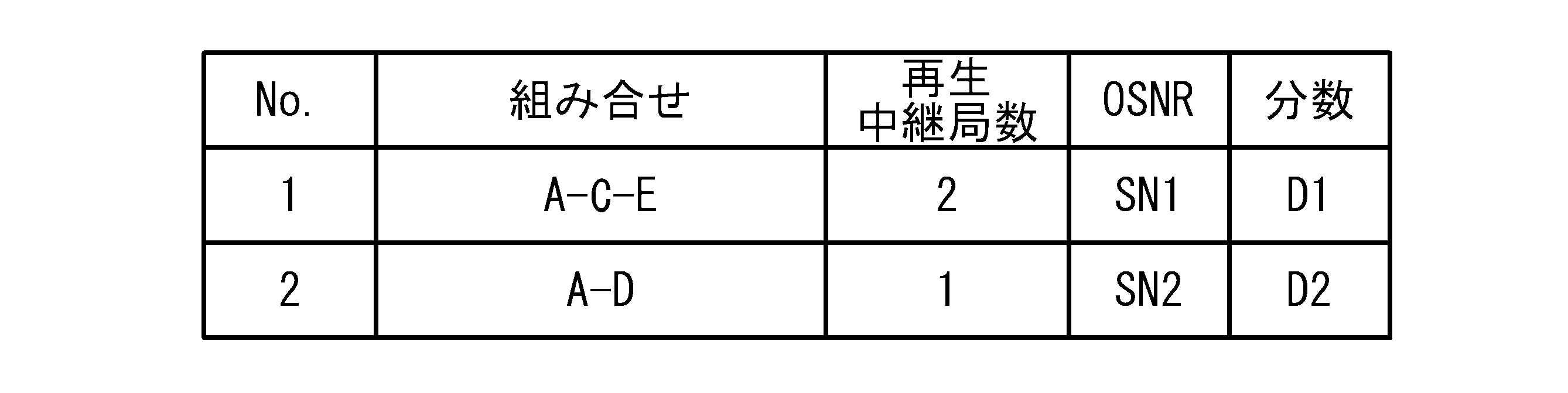
図9のステップS42において、送信端21から受信端25への光信号の伝送を構成する伝送可と判定された区間の組み合わせを決定する。表2において、組み合わせNo.1の場合、付加する再生中継局50の数は2である。組み合わせNo.1での送信端21から受信端25の光伝送特性を評価する。評価の結果、光SN比はSN1、分散特性はD1である。組み合わせNo.2の場合、付加する再生中継局50の数は1である。組み合わせNo.2での送信端21から受信端25の光伝送特性は、光SN比がSN2、分散特性がD2である。最も適した組み合わせの決定は、例えば、再生中継局50の個数が少ないことと、光SN比や分散特性等の信号品質が良いことと、の少なくとも1つを重みとし、例えばDijkstra法等の最小経路検索法を用い行なう。図10において、例えば組み合わせNo.1の組み合わせに決定する。
図9のステップS42において、決定された組み合わせの区間A、Dの両端を再生中継局50とする。送信端21および受信端25はすでに再生中継局50であるから中継局22を再生中継局50とする。以上により、大区間内の再生中継局50の配置が終了する。
実施例1によれば、伝送可否を判定する図9のステップS32からS38においては、図4(d)のように、複数の区間(例えば中継局13から15の区間と中継局15から19の区間)を包含する区間(中継局13から19の区間)では、第2伝送速度での伝送が成立する。しかし、図4(c)のように、複数の区間のいずれか(例えば中継局15から19の区間)では第2伝送速度での伝送が成立しない。このような判定条件を含む。このような場合、図9のステップS32のように複数の中継局のうち、光信号の再生が可能な再生中継局50を配置可能な任意の2つ中継局を結ぶ区間を抽出する。ステップS34のように、第2伝送速度の光信号に対し伝送可否を判定する。ステップS42のように、送信端から受信端への光信号の伝送を構成する伝送可と判定された区間の組み合わせを決定する。これにより、例えば図4(c)の中継局の配置でなく、図4(d)の中継局の配置が選択される。よって、光伝送システムに再生中継局50を適切に配置することができる。
図9のステップS32からS38において、ステップS30で抽出した集合の全ての区間に対し、第2伝送速度の光信号に対し伝送可否を判定することができる。これにより、より適切に再生中継局50を配置することができる。
実施例のように、第2伝送速度は前記第1伝送速度より大きいことが好ましい。また、第1伝送速度の光信号は、強度変調された光信号であり、第2伝送速度の光信号は、位相変調された光信号であることが好ましい。この場合、図5(a)および図5(b)で説明したように、2つの再生中継局50間の区間で伝送可能である場合であっても、その区間を包含する区間では伝送不可の場合が起こりうる。よって、実施例1の中継局の配置方法を用いることにより、適切に再生中継局50を配置することができる。
また、図9のステップS42において、送信端21から受信端25の区間の数に基づき、伝送可と判定された区間の組み合わせを決定することができる。これにより、再生中継局の個数が少ない再生中継局50の配置とすることができる。
さらに、図9のステップS42において送信端21から受信端25への第2伝送速度の光信号の伝送の信号品質に基づき、伝送可と判定された区間の組み合わせを決定することができる。信号品質としては、受信端19における光SN比および分散特性以外に光信号の強度を用いることもできる。これにより、信号品質の良い再生中継局50の配置とすることができる。
さらに、図9のステップS42において、最小経路検索法を用い前記伝送可と判定された区間の組み合わせを決定することができる。これにより、より適切に再生中継局50を配置することができる。
以上、本発明の実施例について詳述したが、本発明は係る特定の実施例に限定されるものではなく、特許請求の範囲に記載された本発明の要旨の範囲内において、種々の変形・変更が可能である。
Claims (8)
- 第1伝送速度の光信号を送信端から受信端に伝送可能なように配置された複数の中継局を備えた光伝送システムにおける中継局の配置方法であって、
前記複数の中継局のうち、光信号の再生が可能な再生中継局を配置可能な任意の2つ中継局を結ぶ区間に対し、前記第1伝送速度と異なる第2伝送速度の光信号に対し伝送可否を判定するステップと、
前記送信端から前記受信端への光信号の伝送を構成する伝送可と判定された区間の組み合わせを決定するステップと、
決定された組み合わせの各区間の両端を、再生中継局を配置すべき中継局とするステップと、を含み、
前記伝送可否を判定するステップは、複数の前記区間を包含する区間では成立するが、前記複数の区間のいずれかでは成立しない判定条件を含むことを特徴とする中継局の配置方法。 - 前記伝送可否を判定するステップは、前記複数の中継局のうち、光信号の再生が可能な再生中継局を配置可能な任意の2つ中継局を結ぶ全ての区間に対し、前記第1伝送速度と異なる第2伝送速度の光信号に対し伝送可否を判定するステップであることを特徴とする請求項1記載の中継局の配置方法。
- 前記第2伝送速度は前記第2伝送速度より大きいことを特徴とする請求項1または2記載の中継局の配置方法。
- 前記第1伝送速度の光信号は、強度変調された光信号であり、
前記第2伝送速度の光信号は、位相変調された光信号であることを特徴とする請求項1から3のいずれか一項記載の中継局の配置方法。 - 前記伝送可と判定された区間の組み合わせを決定するステップは、前記送信端から前記受信端の区間の数に基づき、前記伝送可と判定された区間の組み合わせを決定することを特徴とする請求項1から4のいずれか一項記載の中継局の配置方法。
- 前記伝送可と判定された区間の組み合わせを決定するステップは、前記送信端から前記受信端への前記第2伝送速度の光信号の伝送の信号品質に基づき、前記伝送可と判定された区間の組み合わせを決定することを特徴とする請求項1から4のいずれか一項記載の中継局の配置方法。
- 前記伝送可と判定された区間の組み合わせを決定するステップは、最小経路検索法を用い前記伝送可と判定された区間の組み合わせを決定することを特徴とする請求項1から6のいずれか一項記載の中継局の配置方法。
- 第1伝送速度の光信号を送信端から受信端に伝送可能なように配置された複数の中継局を備えた光伝送システムにおける中継局の配置を行なう中継局配置装置であって、
前記複数の中継局のうち、光信号の再生が可能な再生中継局を配置可能な任意の2つ中継局を結ぶ区間に対し、前記第1伝送速度と異なる第2伝送速度の光信号に対し伝送可否を判定する判定部と、
前記送信端から前記受信端への光信号の伝送を構成する伝送可と判定された区間の組み合わせを決定する決定部と、
決定された組み合わせの各区間の両端を、再生中継局を配置すべき中継局とする配置部と、を含み、
前記判定部は、複数の前記区間を包含する区間では成立するが、前記複数の区間のいずれかでは成立しない判定条件を含むことを特徴とする中継局配置装置。
Priority Applications (3)
| Application Number | Priority Date | Filing Date | Title |
|---|---|---|---|
| PCT/JP2009/055087 WO2010106628A1 (ja) | 2009-03-16 | 2009-03-16 | 中継局の配置方法および中継局配置装置 |
| JP2011504640A JP5229380B2 (ja) | 2009-03-16 | 2009-03-16 | 中継局の配置方法および中継局配置装置 |
| US13/206,049 US8615172B2 (en) | 2009-03-16 | 2011-08-09 | Relay station arrangement method and relay station arrangement device |
Applications Claiming Priority (1)
| Application Number | Priority Date | Filing Date | Title |
|---|---|---|---|
| PCT/JP2009/055087 WO2010106628A1 (ja) | 2009-03-16 | 2009-03-16 | 中継局の配置方法および中継局配置装置 |
Related Child Applications (1)
| Application Number | Title | Priority Date | Filing Date |
|---|---|---|---|
| US13/206,049 Continuation US8615172B2 (en) | 2009-03-16 | 2011-08-09 | Relay station arrangement method and relay station arrangement device |
Publications (1)
| Publication Number | Publication Date |
|---|---|
| WO2010106628A1 true WO2010106628A1 (ja) | 2010-09-23 |
Family
ID=42739299
Family Applications (1)
| Application Number | Title | Priority Date | Filing Date |
|---|---|---|---|
| PCT/JP2009/055087 Ceased WO2010106628A1 (ja) | 2009-03-16 | 2009-03-16 | 中継局の配置方法および中継局配置装置 |
Country Status (3)
| Country | Link |
|---|---|
| US (1) | US8615172B2 (ja) |
| JP (1) | JP5229380B2 (ja) |
| WO (1) | WO2010106628A1 (ja) |
Citations (5)
| Publication number | Priority date | Publication date | Assignee | Title |
|---|---|---|---|---|
| JP2005086521A (ja) * | 2003-09-09 | 2005-03-31 | Fujitsu Ltd | 光ネットワーク設計方法および光ネットワーク設計装置 |
| JP2005295126A (ja) * | 2004-03-31 | 2005-10-20 | Fujitsu Ltd | 分散補償方法及び補償ノード装置 |
| JP2006042279A (ja) * | 2004-07-30 | 2006-02-09 | Fujitsu Ltd | ネットワーク設計装置及びプログラム |
| JP2006245706A (ja) * | 2005-02-28 | 2006-09-14 | Fujitsu Ltd | 光伝送システム、分散補償器内蔵ノードおよび波長分散補償方法 |
| JP2008507223A (ja) * | 2004-07-22 | 2008-03-06 | エム コミュニケーションズ ソシエタ ペル アチオニ | 波長分割多重光通信リンクにおける再生または非再生中継器の数と位置の最適化. |
Family Cites Families (3)
| Publication number | Priority date | Publication date | Assignee | Title |
|---|---|---|---|---|
| JP2004048477A (ja) | 2002-07-12 | 2004-02-12 | Fujitsu Ltd | ネットワーク設計装置 |
| WO2004088922A1 (ja) * | 2003-03-31 | 2004-10-14 | Fujitsu Limited | ネットワーク設計装置 |
| JP4312698B2 (ja) * | 2004-11-08 | 2009-08-12 | 富士通株式会社 | 波長多重伝送システムを適用した光伝送ネットワーク設計方法 |
-
2009
- 2009-03-16 JP JP2011504640A patent/JP5229380B2/ja not_active Expired - Fee Related
- 2009-03-16 WO PCT/JP2009/055087 patent/WO2010106628A1/ja not_active Ceased
-
2011
- 2011-08-09 US US13/206,049 patent/US8615172B2/en not_active Expired - Fee Related
Patent Citations (5)
| Publication number | Priority date | Publication date | Assignee | Title |
|---|---|---|---|---|
| JP2005086521A (ja) * | 2003-09-09 | 2005-03-31 | Fujitsu Ltd | 光ネットワーク設計方法および光ネットワーク設計装置 |
| JP2005295126A (ja) * | 2004-03-31 | 2005-10-20 | Fujitsu Ltd | 分散補償方法及び補償ノード装置 |
| JP2008507223A (ja) * | 2004-07-22 | 2008-03-06 | エム コミュニケーションズ ソシエタ ペル アチオニ | 波長分割多重光通信リンクにおける再生または非再生中継器の数と位置の最適化. |
| JP2006042279A (ja) * | 2004-07-30 | 2006-02-09 | Fujitsu Ltd | ネットワーク設計装置及びプログラム |
| JP2006245706A (ja) * | 2005-02-28 | 2006-09-14 | Fujitsu Ltd | 光伝送システム、分散補償器内蔵ノードおよび波長分散補償方法 |
Also Published As
| Publication number | Publication date |
|---|---|
| US8615172B2 (en) | 2013-12-24 |
| US20110293269A1 (en) | 2011-12-01 |
| JPWO2010106628A1 (ja) | 2012-09-20 |
| JP5229380B2 (ja) | 2013-07-03 |
Similar Documents
| Publication | Publication Date | Title |
|---|---|---|
| JP5644375B2 (ja) | 光伝送装置および光伝送システム | |
| US8224190B2 (en) | Channel assignment method and apparatus for wavelength-division-multiplexed transmission system | |
| US8401383B2 (en) | Data transmission method and network for transmitting a digital optical signal over optical transmission links and networks | |
| US8265485B2 (en) | Optical transmission system and method for chromatic dispersion compensation | |
| CN104104447A (zh) | 光功率均衡方法及装置 | |
| US20110026927A1 (en) | Transmission apparatus, transmission system, and method of communication | |
| JP5648436B2 (ja) | プリエンファシス制御方法 | |
| Pedro et al. | Cost-effective strategies to scale the capacity<? TeX\break?> of regional optical transport networks | |
| US20120294604A1 (en) | Optical protection and switch enabled optical repeating | |
| US7277648B2 (en) | Network element for use in an optical communication network, in particular a DWDM communication network | |
| US20120141121A1 (en) | Optical transmission equipment | |
| Bocoi et al. | Cost comparison of networks using traditional 10 and 40 Gb/s transponders versus OFDM transponders | |
| EP2333990B1 (en) | Stable optical MIMO transmission system over multimode fiber | |
| US9130692B2 (en) | Reconfigurable optical add/drop multiplexer network element for C-band and L-band optical signals | |
| Nag et al. | On the effect of channel spacing, launch power, and regenerator placement on the design of mixed-line-rate optical networks | |
| US20110103790A1 (en) | Method and System for Compensating for Optical Impairment in an Optical Signal | |
| JP5229380B2 (ja) | 中継局の配置方法および中継局配置装置 | |
| WO2022168303A1 (ja) | 光通信システム、制御装置、及び、品質補償方法 | |
| EP2053771A1 (en) | Method for optimizing optical amplification in an optical network | |
| Pedro et al. | High-performance versus power-efficient coherent optical interfaces: spectral efficiency and hardware count comparison | |
| US20110091204A1 (en) | Method and system for deploying an optical demodulator arrangement in a communications network | |
| EP1427122A2 (en) | Bidirectional wavelength division multiplexing self-healing ring network | |
| JP2018182404A (ja) | ネットワーク制御装置、ネットワーク制御方法およびプログラム | |
| JP7639894B2 (ja) | ネットワーク管理装置、通信装置及びネットワーク管理システム | |
| JP5871642B2 (ja) | コヒーレント伝送システム及び方法 |
Legal Events
| Date | Code | Title | Description |
|---|---|---|---|
| 121 | Ep: the epo has been informed by wipo that ep was designated in this application |
Ref document number: 09841834 Country of ref document: EP Kind code of ref document: A1 |
|
| WWE | Wipo information: entry into national phase |
Ref document number: 2011504640 Country of ref document: JP |
|
| NENP | Non-entry into the national phase |
Ref country code: DE |
|
| 122 | Ep: pct application non-entry in european phase |
Ref document number: 09841834 Country of ref document: EP Kind code of ref document: A1 |