WO2010104153A1 - メッセージを中継する中継装置およびプログラム - Google Patents
メッセージを中継する中継装置およびプログラム Download PDFInfo
- Publication number
- WO2010104153A1 WO2010104153A1 PCT/JP2010/054129 JP2010054129W WO2010104153A1 WO 2010104153 A1 WO2010104153 A1 WO 2010104153A1 JP 2010054129 W JP2010054129 W JP 2010054129W WO 2010104153 A1 WO2010104153 A1 WO 2010104153A1
- Authority
- WO
- WIPO (PCT)
- Prior art keywords
- message
- synchronization message
- communication device
- time
- residence time
- Prior art date
- Legal status (The legal status is an assumption and is not a legal conclusion. Google has not performed a legal analysis and makes no representation as to the accuracy of the status listed.)
- Ceased
Links
Images












Classifications
-
- H—ELECTRICITY
- H04—ELECTRIC COMMUNICATION TECHNIQUE
- H04J—MULTIPLEX COMMUNICATION
- H04J3/00—Time-division multiplex systems
- H04J3/02—Details
- H04J3/06—Synchronising arrangements
- H04J3/0635—Clock or time synchronisation in a network
- H04J3/0638—Clock or time synchronisation among nodes; Internode synchronisation
- H04J3/0658—Clock or time synchronisation among packet nodes
- H04J3/0661—Clock or time synchronisation among packet nodes using timestamps
- H04J3/0667—Bidirectional timestamps, e.g. NTP or PTP for compensation of clock drift and for compensation of propagation delays
-
- H—ELECTRICITY
- H04—ELECTRIC COMMUNICATION TECHNIQUE
- H04J—MULTIPLEX COMMUNICATION
- H04J3/00—Time-division multiplex systems
- H04J3/02—Details
- H04J3/06—Synchronising arrangements
- H04J3/0635—Clock or time synchronisation in a network
- H04J3/0685—Clock or time synchronisation in a node; Intranode synchronisation
Definitions
- the present invention relates to a relay device and a program for relaying a message.
- Non-patent Document 1 defines PTP (Precision Time Protocol), which is a protocol for performing highly accurate time synchronization.
- PTP Precision Time Protocol
- the slave node transmits and receives the Sync message periodically transmitted from the master node and the Delay_Req message transmitted from the slave node to the master node.
- a time lag with respect to the master node is obtained from the transmission time and the reception time.
- IEEE Std 1588 “IEEE Standard for a Precision Clock Synchronization Protocol for Networked Measurement and Control Systems”
- the transmission delay is the same when a message is transmitted from the master node to the slave node and when a message is transmitted from the slave node to the master node. For this reason, when the transmission delays are not equal to each other, there is a problem that an error occurs when calculating the time and the time synchronization accuracy is lowered. For example, if another node such as a network switch exists between the master node and the slave node, and the node relays the message, the transmission delay is not equal because the queuing delay in the node occurs. There is a case.
- the present invention has been made in view of the above, and an object of the present invention is to provide a device and a program that can execute time synchronization between communication devices that relay messages with high accuracy.
- the present invention provides a relay device that relays a message transmitted and received between a first communication device and a second communication device, the second communication device being A first reception unit that receives a first synchronization message including a transmission time as a destination from the first communication device, and a predicted value of a stay time until the first synchronization message is transmitted to the second communication device.
- a calculation unit that calculates a first dwell time; a first transmission control unit that transmits the first synchronization message to the second communication device after the first dwell time has elapsed since receiving the first synchronization message; A second receiver that receives the second synchronization message transmitted from the second communication device and that is transmitted with the first communication device as a destination in response to the first synchronization message, and receives the second synchronization message. Shi And a second transmission control unit that transmits the second synchronization message to the first communication device after the first residence time calculated for the corresponding first synchronization message has elapsed. And
- the present invention is also a relay device that relays a message transmitted and received between the first communication device and the second communication device, wherein the first synchronization message including the transmission time is sent to the second communication device as a destination.
- a first receiving unit that receives from the first communication device; a first calculation unit that calculates a first dwell time that is a predicted value of a dwell time until the first synchronization message is transmitted to the second communication device; Adding the calculated first residence time to the first synchronization message, and adding the first residence time after the first residence time has elapsed since the first synchronization message was received.
- a first transmission control unit that transmits a synchronization message to the second communication device; and a second synchronization message that is transmitted to the first communication device in response to the first synchronization message and includes a transmission time.
- Equipment A second receiving unit for receiving, a second calculating unit for calculating a second dwell time which is a predicted value of a dwell time until the second synchronization message is transmitted to the first communication device, and the calculated first 2 dwell time is added to the second synchronization message, and after the second dwell time has elapsed since the reception of the second synchronization message, the second synchronization message with the second dwell time added is added to the first synchronization message.
- a second transmission control unit that transmits to the communication device.
- the present invention is also a relay device that relays messages transmitted and received between the first communication device and the second communication device, and is n (n is an integer of 2 or more) in a FIFO (First In First Out) system. ),
- a transmission control unit that acquires a message from the storage unit by a FIFO method, and transmits the acquired message to a destination specified by the acquired message; and the second communication device.
- a first receiver that receives a first synchronization message as a destination and including a transmission time from the first communication device; and a first receiver that transmits the first synchronization device as a destination according to the first synchronization message and includes a transmission time.
- a second receiving unit for receiving two synchronization messages from the second communication device, and the first synchronization message and the second synchronization message for the FIFO method of the storage unit.
- it characterized by comprising a storage unit for storing the position output to the n-th and.
- the present invention is a relay device that relays a message transmitted and received between the first communication device and the second communication device, and receives a message addressed to the second communication device from the first communication device.
- a first receiving unit that stores the first message determining unit that determines whether the received message is a first synchronization message including a transmission time, and a message that is determined to be the first synchronization message
- a first storage unit, a second storage unit that stores a message determined not to be the first synchronization message, and a message stored in the first storage unit from a message stored in the second storage unit
- a first transmission control unit that preferentially transmits to the second communication device; a second reception unit that receives a message addressed to the first communication device from the second communication device; and a received message.
- the third storage unit, the fourth storage unit that stores the message determined not to be the second synchronization message, and the message stored in the third storage unit from the message stored in the fourth storage unit And a second transmission control unit that preferentially transmits to the first communication device.
- the present invention is a program that can be executed by the above apparatus.
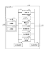
- FIG. 2 is a block diagram illustrating an example of an internal configuration of a network switch according to the first embodiment.
- the block diagram which shows an example of the detailed structure of the input / output port of 1st Embodiment.
- the block diagram which shows an example of a structure of the network switch concerning 2nd Embodiment.
- the block diagram which shows an example of the detailed structure of the input / output port of 2nd Embodiment.
- the block diagram which shows an example of the detailed structure of the input / output port of 3rd Embodiment.
- the block diagram which shows an example of a structure of the network switch concerning 4th Embodiment.
- the figure which shows the structural example of the PTP body of a Delay_Req completion message The block diagram which shows an example of the detailed structure of the input / output port of 4th Embodiment.
- FIG. 10 is a sequence diagram of time synchronization processing according to the fourth embodiment.
- the relay apparatus is connected to a master node and a slave node of IEEE 1588 which is a communication apparatus, and a time synchronization message transmitted from the master node and a time synchronization message transmitted from the slave node. Control is performed so that the staying time in the relay apparatus matches the message.
- FIG. 1 is a diagram illustrating a configuration example of a communication system including a network switch 100 which is a relay device according to the first embodiment.
- the communication system according to the first embodiment includes a network switch 100, a master node 2, and a slave node 3.
- the master node 2 and the slave node 3 are connected to the network switch 100 by a cable such as an Ethernet (registered trademark) cable. In the following description, it is assumed that the master node 2 and the slave node 3 are connected by a cable compliant with Ethernet (registered trademark).
- the master node 2 and the slave node 3 are implemented with IEEE 1588, and operate as masters and slaves in the master-slave hierarchy defined by IEEE 1588, respectively.
- the communication system of this embodiment can be applied to a substation system in which the master clock with a built-in atomic clock is the master node 2 and the protection relay device that transmits a trip signal to the circuit breaker is the slave node 3. Since trip signals are required to be transmitted simultaneously to a plurality of circuit breakers by a high time system, these devices need to be synchronized in time.
- the relay device is not limited to a network switch, and can be applied to any conventionally used relay device such as a router as long as it can relay a message for time synchronization.
- a case where PTP defined in IEEE 1588 is used as a protocol for time synchronization will be described as an example.
- the time synchronization message in this case is hereinafter referred to as a PTP message.
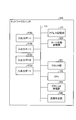
- FIG. 2 is a block diagram showing an example of the internal configuration of the network switch 100.
- the network switch 100 includes a correspondence storage unit 121, an address storage unit 122, input / output ports 110a, 110b, 110c, and 110d, a clock unit 101, a CPU 102, and a calculation unit 103.
- Each component is connected by an internal bus 131 and transmits / receives data to / from each other via the internal bus 131.
- the correspondence storage unit 121 associates a predetermined parameter included in the Sync message, which is a PTP message transmitted from the master node 2 to the slave node 3, and information that can specify the residence time when the Sync message is transmitted.
- FIG. 3 is a diagram illustrating an example of a data structure of data stored in the correspondence storage unit 121.
- the correspondence storage unit 121 includes, in one entry, a sender (source) address of an Ethernet (registered trademark) header (hereinafter referred to as “ether header”), a destination address of an ether header, and a PTP header. Sequence number, message reception time, and message transmission time.
- the information which can specify residence time is not restricted to this.
- the residence time itself may be stored.
- the address storage unit 122 stores the addresses of the nodes connected to the input / output ports 110a, 110b, 110c, and 110d. With this information, the port to which the node to which the message is to be transferred is connected can be specified.
- correspondence storage unit 121 and the address storage unit 122 can be configured by any commonly used storage medium such as an HDD (Hard Disk Drive), an optical disk, a memory card, and a RAM (Random Access Memory).
- HDD Hard Disk Drive
- optical disk an optical disk
- memory card an optical disk
- RAM Random Access Memory
- the clock unit 101 generates a clock signal.
- the CPU 102 is a processor that controls various processes executed in the network switch 100.
- the input / output ports 110a, 110b, 110c, and 110d are ports to which cables for connecting to each node are connected. Since the input / output ports 110a, 110b, 110c, and 110d have the same configuration, they may be simply referred to as the input / output port 110 below. Further, the number of input / output ports 110 is not limited to four. In the following description, it is assumed that the master node 2 and the slave node 3 are connected to the input / output port 110a and the input / output port 110b, respectively.
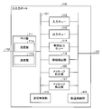
- FIG. 4 is a block diagram showing an example of a detailed configuration of the input / output port 110.
- the input / output port 110 includes a PHY (PHYsical layer) unit 111, an input queue 112, an output queue 113, a dedicated output queue 114, a connection detection unit 115, a time detection unit 116, A message detection unit 117, a transmission control unit 118, and a transfer control unit 119 are provided. These are connected by an internal bus 131 and can exchange data with each other.
- PHY PHYsical layer
- the PHY unit 111 executes processing related to the physical layer of the OSI reference model.
- the PHY unit 111 includes a receiving unit 111a and a transmitting unit 111b as a more detailed configuration.
- the receiving unit 111a receives a message from the cable 132. Specifically, when an electrical signal representing a message arrives from the cable 132, the receiving unit 111a converts the electrical signal into digital information and passes it to the message detection unit 117.
- the transmission unit 111b transmits a message to the cable 132. Specifically, the transmission unit 111b converts a bit string representing a message to be transmitted into a signal in a format compliant with the Ethernet (registered trademark) specification, and transmits the signal to the cable 132.
- the input queue 112 is a queue that temporarily stores received messages.
- the input queue 112 can temporarily store a plurality of messages.
- the maximum length representing the number of messages that can be stored in the input queue 112 is represented as Q_imax.
- the output queue 113 is a queue that temporarily stores messages to be output to the cable 132.
- the output queue 113 outputs a stored message for each predetermined clock (hereinafter referred to as clock C).
- the output queue 113 can temporarily store a plurality of messages.
- the maximum length representing the number of messages that can be stored in the output queue 113 is represented as Q_omax. Note that the maximum length Q_imax of the input queue 112 and the maximum length Q_omax of the output queue 113 are fixed values.
- the dedicated output queue 114 is a queue that temporarily stores a predetermined PTP message.
- the dedicated output queue 114 is controlled by the transmission control unit 118 to output the stored message at the scheduled transmission time calculated by the calculation unit 103.
- the connection detection unit 115 detects whether or not a node is connected via the cable 132. For example, the connection detection unit 115 detects whether or not the node is connected based on whether or not a predetermined signal indicating that the node is active is received via the cable 132. When the cable 132 is connected and the node is active, the connection detection unit 115 holds ON information as the connection state. In addition, the connection detection unit 115 holds the off information as the connection state when the cable 132 is not connected or when the node is not active.
- the connection detection unit 115 of the input / output port 110a and the input / output port 110b receives the on information. keeping.
- the input / output port 110c and the input / output port 110d hold off information because the nodes are not connected.
- the time detection unit 116 detects the time when the message is received (reception time). For example, the time detection unit 116 receives the time information from the clock unit 101 to detect the message reception time, and holds the detected reception time.
- the message detection unit 117 detects the type of the received message. Specifically, the message detection unit 117 detects the type of message by referring to the type of the Ether header and the message type of the PTP header of the PTP message.
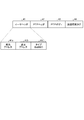
- FIG. 5 is a diagram illustrating an example of a message format of the received PTP message.
- the PTP message includes an Ethernet header 41, a PTP header 42, a PTP body 43, and a transmission time tag 44.
- the PTP message may be carried as a UDP / IP communication packet depending on the system.
- an Ethernet header 41 is added because it is carried by Ethernet (registered trademark).
- the ether header 41 includes a destination address 41a, a sender address 41b, and a type 41c.
- a destination address 41a a MAC address, a broadcast address, a multicast address, and the like of the destination node are assigned.
- the sender address 41b is assigned the MAC address of the sender node.
- Type 41c represents the contents of the payload. In the case of PTP, “0x8807” is assigned to the type 41c.
- the PTP header 42 is a header for storing parameters defined by PTP.
- FIG. 6 is a diagram illustrating an example of a detailed configuration of the PTP header 42.
- the PTP header 42 includes a message type 42a, a version 42b, a message length 42c, a domain number 42d, a flag field 42e, a collection field 42f, a source port ID 42g, a sequence ID 42h, It consists of a control field 42i and a log message interval 42j.
- the message type 42a is assigned a different value depending on the type of PTP message.
- the version 42b represents the version of the PTP protocol.
- the message length 42c is the length of the message including the PTP header.
- the domain number 42d is an identifier representing a range in which time is synchronized.
- the flag field 42e is detailed information given by the message.
- the collection field 42f is a time when the message stays in the IEEE 1588 node other than the master node 2 and the slave node 3.
- the source port ID 42g indicates the identifier of the transmission port of the sender of the IEEE 1588 node.
- the sequence ID 42h indicates an identifier of the PTP message.
- the control field 42i is an identifier to which a different value is assigned depending on the message.
- the log message interval 42j has a different role depending on the message.
- FIG. 7 to 9 are diagrams showing an example of the PTP body 43.
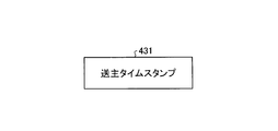
- FIG. 7 shows the structure of the PTP body 43 when the PTP message is a Sync message.
- the PTP body 431 of the Sync message is configured by a sender time stamp.
- the sender time stamp represents an approximate time when the Sync message was transmitted from the master node 2.
- the destination address 41a of the Ethernet header 41 is a multicast address
- the message type 42a of the PTP header 42 is “0”.
- the PTP body of the Delay_Req message has the same configuration as the PTP body 431 of the Sync message, and can hold the sender time stamp.
- the MAC address of the master node 2 is set in the destination address 41a of the ether header 41
- the MAC address of the slave node 3 is set in the sender address 41b
- the value of the message type 42a in the PTP header 42 is set to “1”. Is done.
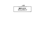
- FIG. 8 shows the structure of the PTP body 43 when the PTP message is a follow_Up message.
- the PTP body 432 of the Follow_Up message is configured by a precise sender time stamp.
- the precise sender time stamp is the time when the Sync message was actually transmitted.
- the destination address 41a of the Ethernet header 41 is a multicast address.
- the MAC address of the master node 2 is set in the sender address 41b, “0x0087” is set in the type 41c, and “8” is set in the message type 42a of the PTP header 42.
- FIG. 9 shows the structure of the PTP body 43 when the PTP message is a Delay_Resp message.
- the PTP body 433 of the Delay_Resp message includes a reception time stamp and a request port ID.
- the reception time stamp holds the time when the Delay_Req message is received.
- the request port ID holds the port ID of the transmission destination that has transmitted the Delay_Req message.
- the Delay_Resp message is unicast.
- the MAC address of the master node 2 is set as the sender address of the ether header
- the MAC address of the slave node 3 is set as the destination address
- “9” is set as the value of the message type 42a of the PTP header 42.
- the message detection unit 117 detects the message type by referring to each header of the message configured as described above. For example, when the type 41c of the Ethernet header 41 is “0x8807” and the message type of the PTP header is “0”, the message detection unit 117 detects that the received message is a Sync message. In this case, the message detection unit 117 includes the sender address 41b of the Ethernet header 41 of the Sync message, the destination address 41a of the Ethernet header 41, the sequence ID 42h of the PTP header 42, and the reception time detected by the time detection unit 116. Is created and added to the correspondence storage unit 121.
- the transmission control unit 118 controls the transmission timing of messages stored in the output queue 113 and the dedicated output queue 114. For example, the transmission control unit 118 controls to transmit the message stored in the output queue 113 to the cable 132 via the PHY unit 111 for each clock C. In addition, the transmission control unit 118 controls the message stored in the dedicated output queue 114 to be transmitted to the cable 132 via the PHY unit 111 at the scheduled transmission time calculated by the calculation unit 103.
- the transfer control unit 119 controls processing for transferring a message stored in the input queue 112 to the output queue 113 of another input / output port 110. For example, for each clock C, the transfer control unit 119 acquires one of the messages stored in the input queue 112, and the input / output to which the destination node of the acquired message is connected via the internal bus 131. Transfer to the output queue 113 of the port 110.
- the calculation unit 103 calculates a predicted value of the time (stay time) that the message input from the input / output port 110 stays in the network switch 100. Specifically, the calculation unit 103 estimates the residence time according to the following algorithm.
- the calculation unit 103 first detects the position of the input queue 112 that is accessed for transfer to the output queue 113 when the received message is sent to the input queue 112. Then, the calculation unit 103 calculates S + C ⁇ (T ⁇ Q_imax + Q_omax), which is the maximum value of the time expected to stay until the received message is output, as the residence time. Note that S is a value determined in advance as the time for which the received message is sent to the input queue 112.
- the calculation unit 103 may be configured as software that operates by the CPU 102 instead of being realized by a hardware circuit different from the CPU 102.
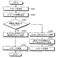
- FIG. 10 is a flowchart illustrating an overall flow of the relay processing in the first embodiment.
- the receiving unit 111a of the PHY unit 111 receives a message transmitted from the master node 2 or the slave node 3 (step S1001).
- the time detection unit 116 detects and holds the message reception time (step S1002).
- the message detection unit 117 detects the type of message with reference to the ether header type and the PTP header message type (step S1003).
- the message detection unit 117 determines whether or not the received message is a Sync message (step S1004).
- the message detection unit 117 creates an entry including the sender address 41b of the Ether header 41 of the Sync message, the sequence ID 42h of the PTP header 42, and the reception time, and stores the correspondence. It adds to the part 121 (step S1005).
- the calculation unit 103 calculates the stay time of the Sync message (step S1006).
- step S1007 the message detection unit 117 further determines whether or not the received message is a Delay_Req message (step S1007).
- the calculation unit 103 checks the residence time required when the Sync message corresponding to the received Delay_Req message passes through the network switch 100. That is, the calculation unit 103 searches the correspondence storage unit 121 for an entry having a destination address that matches the sender address of the Ether header of the Delay_Req message (step S1008).
- the calculation unit 103 calculates the dwell time of the Sync message that is the difference between the transmission time and the reception time of the searched entry (step S1009).
- the calculation unit 103 acquires the residence time from the searched entry. Also, the calculation unit 103 calculates the stay time of the Delay_Req message (step S1010).
- the calculation unit 103 determines whether or not the residence time of the Delay_Req message is equal to or less than the residence time of the corresponding Sync message (step S1011). If the stay time of the Delay_Req message is not less than or equal to the stay time of the corresponding Sync message (step S1011: NO), the calculation unit 103 discards the received Delay_Req message (step S1012) and ends the relay process.
- step S1011 When the stay time of the Delay_Req message is equal to or less than the stay time of the corresponding Sync message (step S1011: YES), the calculation unit 103 matches the stay time of the Delay_Req message with the stay time of the corresponding Sync message (step S1013). .
- the calculation unit 103 calculates the scheduled transmission time by adding the calculated dwell time to the message reception time. The message is added to the message transmission time tag 44 (step S1014).
- the calculation unit 103 sends the message with the scheduled transmission time to the input queue 112 of the input / output port 110 that has received the message (step S1015).
- the message sent to the input queue 112 is held until it is transferred to the output queue 113 of another input / output port 110.
- the transfer control unit 119 transfers the message held in the input queue 112 to the output queue 113 of the input / output port 110 to which the destination node is connected (step S1016). .
- the transfer control unit 119 determines the input / output port 110 to which the destination node is connected by referring to the address storage unit 122.
- the transmission control unit 118 of the input / output port 110 to which the message has been transferred acquires the message to be transmitted from the output queue 113 for each clock C (step S1017).
- the message detection unit 117 detects the type of the acquired message using the same method as in step S1003 (step S1018).
- the message detection unit 117 determines whether or not the acquired message is a Sync message or a Delay_Req message (step S1019). When it is a Sync message or a Delay_Req message (step S1019: YES), the message detection unit 117 transfers the acquired message to the dedicated output queue 114 (step S1020).
- the transmission control unit 118 extracts the scheduled transmission time from the transmission time tag of the message, and periodically compares the current time acquired from the clock unit 101 with the transmission time to determine whether the planned transmission time has been reached. It is determined whether or not (step S1021). If it is not the scheduled transmission time (step S1021: NO), the message is held in the dedicated output queue 114 until the scheduled transmission time is reached. If it is the scheduled transmission time (step S1021: YES), the transmission control unit 118 transmits the message held in the dedicated output queue 114 to the destination node via the PHY unit 111 (step S1022).
- step S1019 When it is determined in step S1019 that the message acquired from the output queue 113 is not a Sync message or a Delay_Req message (step S1019: NO), the transmission control unit 118 sends the acquired message to the destination via the PHY unit 111. (Step S1022).
- the transmission control unit 118 updates the entry in the correspondence storage unit 121 (step S1023). For example, when a Sync message is transmitted, the transmission control unit 118 adds the message transmission time and the MAC address of the destination node as the transmission time and destination address of the entry with the matching sequence ID 42h. If there is an entry with the same sender address and destination address (duplicate entry) other than this entry, the transmission control unit 118 deletes the duplicate entry.
- the transmission control unit 118 searches the correspondence storage unit 121 for the Sync message corresponding to the transmitted Delay_Req message using the destination address and the sender address of the ether header.
- the transmission control unit 118 deletes the entry from the correspondence storage unit 121.
- the stay time of the Sync message can be matched with the stay time of the Delay_Req message transmitted as a response to the Sync message. That is, the transmission delay can be matched between the case where the message is transmitted from the master node 2 to the slave node 3 and the case where the message is transmitted from the slave node 3 to the master node 2. This makes it possible to execute time synchronization processing using the reception time of these messages with high accuracy.
- time synchronization processing is realized by a procedure of transmission of a Sync message and Follow_Up message from the master node 2, transmission of a Delay_Req message from the slave node 3, and transmission of a Delay_Resp message from the master node 2.
- the master node 2 periodically transmits a PTP Sync message defined in IEEE 1588.
- the Sync message transmitted from the master node 2 is received by the input / output port 110a of the network switch 100. Since the type 41c of the Ethernet header 41 is “0x8807” and the message type of the PTP header is “0”, the message detection unit 117 detects that the message is a Sync message. Next, the calculation unit 103 estimates the residence time of the Sync message. In addition, the calculation unit 103 calculates the scheduled transmission time by adding the calculated residence time to the reception time. Then, the calculation unit 103 adds a transmission time tag 44 in which the calculated scheduled transmission time is set to the Sync message.
- the Sync message is sent to the input queue 112 and held until it is transferred to the output queue 113 of another input / output port 110b.
- the transfer control unit 119 refers to the address storage unit 122 and detects the input / output port 110 corresponding to the destination address 41a of the Ethernet header of the Sync message.
- the Sync message is transferred to the output queue 113 of the input / output port 110 b and held until the message is transmitted to the slave node 3.
- the message type is determined by the message detection unit 117 in the same procedure as when the message is received. In this case, it is detected that the message is a Sync message and is sent to the dedicated output queue 114.
- the transmission control unit 118 extracts the scheduled transmission time from the transmission time tag, and holds the Sync message in the dedicated output queue 114 until the scheduled transmission time is reached.
- the transmission control unit 118 transmits a Sync message to the slave node 3 when the scheduled transmission time is reached.
- the master node 2 When the Sync message is received by the slave node 3, the master node 2 subsequently transmits a Follow_Up message.
- the time detection unit 116 of the input / output port 110a detects the reception time of the Follow_Up message, similarly to the Sync message.
- the message detection unit 117 checks the Ether header type of the Follow_Up message and the message type of the PTP header. Since the type 41c of the Ethernet header 41 is “0x8807” and the message type of the PTP header is “8”, the message detection unit 117 detects that it is a Follow_Up message. Since the Follow_Up message is a message that transmits the exact time when the Sync message is transmitted, it is not necessary to make the transmission delay symmetrical. Therefore, it is sent to the input queue 112 as it is and transferred to the slave node 3.
- the slave node 3 After the Follow_Up message is received by the slave node 3, the slave node 3 transmits a Delay_Req message to the master node 2.
- the time detection unit 116 of the input / output port 110b detects the reception time of the Delay_Req message, similarly to the Sync message.
- the message detection unit 117 examines the Ether header type of the Delay_Req message and the message type of the PTP header. Since the type 41c of the ether header 41 is “0x8807” and the message type of the PTP header is “1”, the message detection unit 117 detects that the message is a Delay_Req message.
- the calculation unit 103 estimates the residence time of the Delay_Req message in the same manner as in the case of the Sync message. Furthermore, the calculation unit 103 refers to the correspondence storage unit 121 to check the residence time required when the corresponding Sync message has passed through the network switch 100 in the past. Then, the calculation unit 103 compares the residence time obtained by calculation with the residence time of the corresponding Sync message. When the stay time of the Sync message is longer than the stay time of the Delay_Req message, the calculation unit 103 matches the stay time of the Delay_Req message with the stay time of the Sync message.
- the calculation unit 103 calculates the scheduled transmission time in the same manner as the Sync message, adds the transmission time tag 44 to the Delay_Req message, and sends it to the input queue 112.
- the Delay_Req message is transferred from the input queue 112 of the input / output port 110b to the output queue 113 of the input / output port 110a, and the output order is awaited.
- the Delay_Req message is sent to the dedicated output queue 114.
- the transmission control unit 118 extracts the scheduled transmission time from the transmission time tag, and holds the Delay_Req message in the dedicated output queue 114 until the scheduled transmission time is reached.
- the transmission control unit 118 transmits a Delay_Req message to the master node 2 when the scheduled transmission time is reached.
- the master node 2 When receiving the Delay_Req message, the master node 2 immediately transmits a Delay_Resp message to the slave node 3. Like the Follow_Up message, the Delay_Resp message is transferred to the slave node 3 in the network switch 100 without performing any special processing.
- the slave node 3 (1) Sync message transmission time t1 by the master node 2, (2) Time t2 when the Sync message is received by the slave node 3, (3) Delay_Req by the slave node 3.
- time t3 when the message is transmitted and (4) time t4 when the Delay_Req message is received by the master node 2.
- the transmission time t1 in (1) is obtained from the precise sender time stamp of the Follow_Up message.
- the time t4 in (4) is obtained from the reception time stamp of the Delay_Resp message.
- t_o representing the deviation of the clock of the slave node 3 from the clock of the master node 2 can be calculated.
- T_md includes a transmission delay from the master node 2 to the network switch 100, a residence time in the network switch 100, and a transmission delay from the network switch 100 to the slave node 3.
- t_sd is composed of a transmission delay from the slave node 3 to the network switch 100, a residence time in the network switch 100, and a transmission delay from the network switch 100 to the master node 2.
- the residence time of the Delay_Req message transmitted from the slave node can be matched with the residence time of the Sync message transmitted from the master node. Thereby, time synchronization between the master node and the slave node can be executed with high accuracy.
- the relay apparatus estimates the residence time of a time synchronization message, adds the estimated residence time to the message, and transmits the message after the estimated residence time has elapsed.
- FIG. 11 is a block diagram illustrating an example of the configuration of the network switch 200 according to the second embodiment.
- the network switch 200 includes an address storage unit 122, input / output ports 210a, 210b, 210c, and 210d (hereinafter referred to as input / output port 210), a clock unit 101, a CPU 102, and a calculation unit 203. And.
- Each component is connected by an internal bus 131 and transmits / receives data to / from each other via the internal bus 131.
- the correspondence storage unit 121 is deleted, and the functions of the input / output port 210 and the calculation unit 203 are different from those in the first embodiment. Since other configurations and functions are the same as those in FIG. 2 which is a block diagram showing the configuration of the network switch 100 according to the first embodiment, the same reference numerals are given and description thereof is omitted here.
- FIG. 12 is a block diagram illustrating an example of a detailed configuration of the input / output port 210.
- the input / output port 210 includes a PHY unit 111, an input queue 112, an output queue 113, a dedicated output queue 114, a connection detection unit 115, a time detection unit 116, and a message detection unit 217.
- the functions of the message detection unit 217 and the transmission control unit 218 are different from those in the first embodiment. Since other configurations and functions are the same as those in FIG. 4 which is a block diagram showing the configuration of the input / output port 110 according to the first embodiment, the same reference numerals are given and description thereof is omitted here.
- the message detection unit 217 detects the type of the received message in the same manner as the message detection unit 117 of the first embodiment. On the other hand, in the present embodiment, since the correspondence storage unit 121 is not provided, the message detection unit 217 does not have a function of adding an entry to the correspondence storage unit 121.
- the transmission control unit 218 controls the transmission timing of messages stored in the output queue 113 and the dedicated output queue 114, similarly to the transmission control unit 118 of the first embodiment. On the other hand, in this embodiment, since the correspondence storage unit 121 is not provided, the transmission control unit 218 does not have a function of updating the entry in the correspondence storage unit 121.
- the calculation unit 203 calculates a predicted value of the message residence time by the same method as the transmission control unit 118 of the first embodiment. Furthermore, the calculation unit 203 has a function of adding the residence time to the collection field of the PTP header.
- the calculation unit 203 compares the residence time of the Delay_Req message with the function of acquiring the residence time of the Sync message corresponding to the Delay_Req message from the correspondence storage unit 121, the residence time of the Delay_Req message, and the residence time of the Sync message. It does not have a function for matching the message retention time and a function for discarding the Delay_Req message when the retention time cannot be matched.
- FIG. 13 is a flowchart illustrating an overall flow of the relay processing in the second embodiment.
- the message reception process, the reception time detection process, and the message detection process from step S1301 to step S1303 are the same as the process from step S1001 to step S1003 in the network switch 100 according to the first embodiment. Omitted.
- the message detection unit 217 determines whether the received message is a Sync message or a Delay_Req message (step S1304). When it is a Sync message or a Delay_Req message (step S1304: YES), the calculation unit 203 calculates the stay time of the received message (step S1305).
- the calculation unit 203 calculates the scheduled transmission time by adding the calculated residence time to the message reception time, and adds it to the message transmission time tag 44 (step S1306). Next, the calculation unit 203 adds the residence time to the collection field of the PTP header (step S1307).
- steps S1308 to S1315 are the same as steps S1015 to S1022 in the network switch 100 according to the first embodiment, a description thereof will be omitted.
- the relay process is terminated after transmitting the message held in the output queue 113 or the dedicated output queue 114 in step S1315.
- the dwell time is calculated, the dwell time is set in the collection field, and then the message is sent to the time synchronization process taking into account the dwell time set in the collection field Had gone.
- the dwell time is set in the collection field, and then the message is sent to the time synchronization process taking into account the dwell time set in the collection field Had gone.
- it takes more time to calculate the dwell time and actually send the message an error will occur between the dwell time set in the collection field and the actual dwell time, and the accuracy of time synchronization will be reduced. There was a risk of decline.
- the residence time set in the collection field and the actual residence time can be matched with high accuracy by the procedure as described above. That is, the estimated residence time can be set in the collection field, and a message can be transmitted after the estimated residence time has elapsed. As a result, the time synchronization process using the collection field can be executed with high accuracy.
- the master node 2 periodically transmits a PTP Sync message defined in IEEE 1588.
- the Sync message transmitted from the master node 2 is received by the input / output port 210a of the network switch 200.
- the time detection unit 116 of the input / output port 210a detects and holds the reception time of the Sync message by obtaining time information from the clock unit 101.
- the message detection unit 217 checks the type of the Ether header and the message type of the PTP header.
- the message detection unit 217 detects that the type is the sync message because the type 41c of the ether header 41 is “0x8807” and the message type of the PTP header is “0”.
- the calculation unit 203 estimates the residence time of the Sync message. Further, the calculation unit 203 adds the residence time to the reception time to obtain the scheduled transmission time. Next, the calculation unit 203 adds the residence time to the collection field of the PTP header. In addition, the calculation unit 203 adds the transmission time tag 44 to the Sync message. The transmission time tag 44 holds a scheduled transmission time.
- the Sync message is sent to the input queue 112, the output queue 113 of another input / output port 210, and the dedicated output queue 114 of another input / output port 210.
- the slave node 3 Sent to. Since the process at this time is the same as that of the first embodiment, detailed description thereof is omitted.
- the master node 2 transmits a Follow_Up message.
- the network switch 200 receives the Follow_Up message and transfers the received Follow_Up message to the slave node 3. Since the process at this time is the same as that of the first embodiment, detailed description thereof is omitted.
- the slave node 3 After the Follow_Up message is received by the slave node 3, the slave node 3 transmits a Delay_Req message to the master node 2.
- the network switch 200 receives the Delay_Req message, and performs processing such as calculation of the residence time, calculation of the scheduled transmission time, and addition of the residence time to the collection field by the same method as the Sync message.
- the Delay_Req message is transmitted to the master node 2 when the scheduled transmission time is reached. Since the process at this time is the same as that of the first embodiment, detailed description thereof is omitted.
- the master node 2 When receiving the Delay_Req message, the master node 2 immediately transmits a Delay_Resp message to the slave node 3. Like the Follow_Up message, the Delay_Resp message is transferred to the slave node 3 in the network switch 200 without performing any special processing.
- the slave node 3 stays in the network switch 200 at (5) Sync message at the four times (t1 to t4) (1) to (4) described in the first embodiment. It is possible to obtain six times including the time r1, and (6) the time r2 when the Delay_Req message stays in the network switch 200.
- t_o representing the deviation of the clock of the slave node 3 from the clock of the master node 2 can be calculated from these six times.
- T_md includes a transmission delay from the master node 2 to the network switch 200 and a transmission delay from the network switch 200 to the slave node 3.
- t_sd includes a transmission delay from the slave node 3 to the network switch 200 and a transmission delay from the network switch 200 to the master node 2.
- t_o (t2 ⁇ t1 ⁇ r1 ⁇ t4 + t3 + r2) / 2.
- the residence time of the Sync message and the Delay_Req message is estimated, and the estimated residence time has elapsed after the estimated residence time is added to the collection field of each message.
- a message can be sent later. As a result, it is possible to reduce the possibility of an error between the residence time set in the collection field and the actual residence time, and to perform time synchronization between the master node and the slave node with high accuracy.
- the relay apparatus includes an input / output queue common to a plurality of input / output ports, and adds a time synchronization message to the tail of the input / output queue. Thereby, the residence time until the added message is output can be matched.
- FIG. 14 is a diagram illustrating a configuration example of a communication system including the network switch 300 which is a relay device according to the third embodiment.
- the communication system according to the third embodiment includes a network switch 300, a master node 2, and a plurality of slave nodes 3a to 3c.
- the slave nodes 3a to 3c are nodes having the same functions as the slave node 3 of the first and second embodiments.
- the slave nodes 3a to 3c may be simply referred to as the slave node 3.
- FIG. 15 is a block diagram illustrating an example of the internal configuration of the network switch 300.
- the network switch 300 includes an address storage unit 122, input / output ports 310a, 310b, 310c, and 310d (hereinafter referred to as input / output port 310), a clock unit 101, a CPU 102, an input / output queue 304, and a transmission control unit 318. And.
- Each component is connected by an internal bus 131 and transmits / receives data to / from each other via the internal bus 131.
- the correspondence storage unit 121 and the calculation unit 103 are deleted, the function of the input / output port 310, and the input / output queue 304 and the transmission control unit 318 are added.
- the form is different. Since other configurations and functions are the same as those in FIG. 2 which is a block diagram showing the configuration of the network switch 100 according to the first embodiment, the same reference numerals are given and description thereof is omitted here.
- the input / output port 310 is a port to which a cable 132 for connecting to each node is connected.
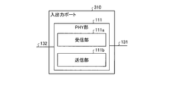
- FIG. 16 is a block diagram illustrating an example of a detailed configuration of the input / output port 310.
- the input / output port 310 includes a PHY unit 111. That is, the third embodiment is different from the first embodiment in that components other than the PHY unit 111 are deleted. Since the configuration and function of the PHY unit 111 are the same as those in the first embodiment, the same reference numerals are given, and description thereof is omitted here.
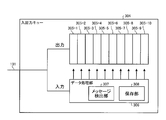
- the input / output queue 304 is a queue for storing messages transmitted and received at each input / output port 310.
- the data processing unit 306 includes a message detection unit 307 and a storage unit 308.
- the message detection unit 307 detects the type of the received message by the same method as the message detection unit 117 of the first embodiment. That is, the message detection unit 307 detects the message type by referring to the type of the Ether header and the message type of the PTP header of the PTP message.
- the storage unit 308 stores the input data in the data block 305. For example, when the received message is a PTP message, the storage unit 308 stores the PTP message in the data block 305 (the last data block 305) output last (nth) by the FIFO method. If there is an empty data block 305 other than the last data block 305, the storage unit 308 creates dummy data and saves the created dummy data in the empty data block 305.
- the storage unit 308 applies the message to the data block 305 having the smallest output order among the empty data block 305 or the data block 305 in which dummy data is stored. Save.
- the storage unit 308 stores the message by replacing the dummy data with the dummy data.
- the transmission control unit 318 acquires data (message) from the input / output queue 304 by the FIFO method at regular time intervals t_q, and transmits the acquired message to the destination node specified by the message. To control. If the transmission control unit 318 acquires dummy data from the input / output queue 304, the transmission control unit 318 discards the acquired data without transmitting it.
- the received PTP message is always input at the end of the input / output queue 304. For this reason, the time from when the PTP message is input to the input / output queue 304 until it is output is constant n ⁇ t_q.
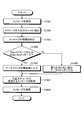
- FIG. 18 is a flowchart illustrating an overall flow of relay processing in the third embodiment.
- the receiving unit 111a of the PHY unit 111 receives a message transmitted from the master node 2 or the slave node 3 (step S1801).
- the PHY unit 111 sends the received message to the input / output queue 304 (step S1802).
- the message detection unit 307 of the input / output queue 304 detects the message type with reference to the Ether header type and the PTP header message type (step S1803).
- the message detection unit 307 determines whether or not the received message is a Sync message or a Delay_Req message (step S1804).
- the storage unit 308 If the message is a Sync message or a Delay_Req message (step S1804: YES), the storage unit 308 inputs the received message at the end of the data block 305 (step S1805). When there is an empty data block 305, the storage unit 308 inputs dummy data to the empty data block 305 and then inputs a message to the end of the data block 305.
- the storage unit 308 inputs the received message to the empty data block 305 closest to the output among the data blocks 305 (step S1806).
- the transmission control unit 318 acquires a message to be transmitted by the FIFO method from the input / output queue 304 at regular time t_q (step S1807). Then, the transmission control unit 318 transmits the acquired message to the destination node specified by the message (step S1808), and ends the relay process.
- the master node 2 periodically transmits a PTP Sync message defined in IEEE 1588.
- the Sync message transmitted from the master node 2 is received by the input / output port 310a of the network switch 300.
- the Sync message is input to the input / output queue 304. Since the Sync message is a PTP message, the storage unit 308 stores the Sync message at the end of the input / output queue 304. Then, the transmission control unit 318 transmits a Sync message to the slave node 3 after elapse of n ⁇ t_q which is a certain time.
- the master node 2 When the Sync message is received by the slave node 3, the master node 2 subsequently transmits a Follow_Up message.
- the Follow_Up message is processed in the same manner as normal data and transferred to the slave node 3.
- the slave node 3 After the Follow_Up message is received by the slave node 3, the slave node 3 transmits a Delay_Req message to the master node 2.
- the network switch 300 When the Delay_Req message is input to the network switch 300, the network switch 300 performs the same processing as the Sync message. That is, the message detection unit 307 of the data processing unit 306 checks the Ether header type of the Delay_Req message and the message type of the PTP header. Since the type 41c of the ether header 41 is “0x8807” and the message type of the PTP header is “1”, the message detection unit 307 detects that it is a Delay_Req message. Further, the storage unit 308 inputs the Delay_Req message at the end of the data block 305 and fills the other empty data block 305 with dummy data. As a result, the Delay_Req message is output from the input / output queue 304 after the dwell time of n ⁇ t_q hours and transmitted to the master node 2.
- the master node 2 When receiving the Delay_Req message, the master node 2 immediately transmits a Delay_Resp message to the slave node 3.
- the Delay_Req message When the Delay_Req message is received by the network switch 300, normal data processing is performed and transferred to the slave node 3.
- a plurality of slave nodes 3 a to 3 c are connected to the network switch 300.
- the network switch 300 may simultaneously receive the Delay_Req message transmitted from the plurality of slave nodes 3a to 3c to the master node 2.
- the storage unit 308 of the data processing unit 306 collects a plurality of messages received from each slave node 3 into one data and inputs them to the end of the data block 305.
- the residence time of each message is n ⁇ t_q, (n + 1) ⁇ t_q, and (n + 2) ⁇ t_q.
- the values are different.
- the residence time can be always a constant value of n ⁇ t_q.
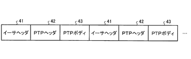
- FIG. 19 is a diagram showing an example of the data format of the Delay_Req message collected into one data.
- FIG. 19 shows an example in which another Delay_Req message is concatenated after the Delay_Req message to form one piece of data.
- the master node 2 that has received such a message processes the message until the second ether header from the top is detected as one Delay_Req message transmitted from a certain slave node 3.
- the master node 2 detects the second ether header and the PTP header, and performs processing as a Delay_Req message transmitted from another slave node 3.
- the master node 2 sets the reception time of the Delay_Req message to be processed second as the same reception time as the Delay_Req message processed first.
- the master node 2 processes the third and subsequent Delay_Req messages in the same manner.
- the master node 2 transmits a Delay_Resp message for each of the plurality of Delay_Req messages.
- the storage unit 308 may be configured to set only the source MAC address (sender address) in the Ethernet header of the second and subsequent Delay_Req messages. This is because the destination address and type are common. As a result, the size of the message to be transmitted can be reduced.
- the relay apparatus includes an input / output queue common to a plurality of input / output ports, and adds a Sync message and a Delay_Req message to the tail of the input / output queue. It is possible to match the residence time until the message is output. Thereby, time synchronization between the master node and the slave node can be executed with high accuracy.
- the relay device directly transfers the time synchronization message to the dedicated output queue in the input / output port to which the destination node is connected. Then, the message input to the dedicated output queue is immediately transmitted to the destination node in preference to the output queue to which the normal message is input. Thereby, the residence time of the message for time synchronization in a relay apparatus can be made constant.
- the relay device transmits a message requesting to transmit a time synchronization message to each of the plurality of slave nodes at different timings. Thereby, it can avoid receiving the message for time synchronization which each slave node transmitted simultaneously.
- the configuration of the communication system according to the present embodiment is the same as that shown in FIG.
- FIG. 20 is a block diagram illustrating an example of the configuration of the network switch 400 according to the fourth embodiment.
- the network switch 400 includes an address storage unit 122, a port state storage unit 423, input / output ports 410a, 410b, 410c, and 410d (hereinafter referred to as input / output ports 410), and a clock unit 101.
- a CPU 102 and a protocol processing unit 405 are provided.
- Each component is connected by an internal bus 131 and transmits / receives data to / from each other via the internal bus 131.
- the correspondence storage unit 121 and the calculation unit 103 are deleted, the port state storage unit 423 and the protocol processing unit 405 are added, and the function of the input / output port 410 is the first implementation.
- the form is different. Since other configurations and functions are the same as those in FIG. 2 which is a block diagram showing the configuration of the network switch 100 according to the first embodiment, the same reference numerals are given and description thereof is omitted here.
- the port state storage unit 423 stores a port state indicating the state of the input / output port 410.
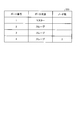
- FIG. 21 is a diagram illustrating an example of a data structure of data stored in the port state storage unit 423.
- the entry of the port state storage unit 423 includes a port number and a port state.
- the port number is a number that identifies the input / output port 410.
- the port state is set to “master” when the master node 2 is connected to the input / output port 410, and is set to “slave” when the slave node 3 is connected to the input / output port 410. Is done.
- the figure shows an example of an entry when the master node 2 is connected to the input / output port 410 of port number 1 and the slave node 3 is connected to the input / output port 410 of port numbers 2, 3, and 4. Has been.
- the protocol processing unit 405 executes various processes compliant with PTP. For example, the protocol processing unit 405 periodically transmits a PTP management request message to each node in order to detect a port state. Further, the protocol processing unit 405 receives a PTP management response message that is a response to the PTP management request message, and analyzes the PTP management response message to detect the port state of each node. The detected port state is stored in the port state storage unit 423.
- the protocol processing unit 405 generates a Delay_Req start message for requesting transmission of the Delay_Req message after the designated start time has elapsed, and transmits it to the slave node 3.
- This Delay_Req start message is an extension of the PTP signaling message.
- FIG. 22 is a diagram illustrating a configuration example of the PTP body of the Delay_Req start message.
- the PTP body 431 of the Delay_Req start message includes a target port ID, a type, a length, an organization ID, an organization subtype, and a start time.
- the target port ID is a destination port ID.
- the type represents the type of PTP signaling message. Since the Delay_Req start message is an organization extension message, the type holds a value of “3”.
- the organization ID holds, for example, an OUI code representing the organization.
- the organization subtype holds a value that is more freely assigned within the organization. Therefore, the unique value representing the Delay_Req start message is the value of the organization ID and the organization subtype.
- the start time holds the time from when the slave node 3 receives the Delay_Req start message until it starts transmitting the Delay_Req message. If the start time is zero, the slave node 3 immediately transmits a Delay_Req message.
- the MAC address of the slave node 3 is held in the destination address 41a of the Ether header 41 of the Delay_Req start message.
- the sender address 41b holds the MAC address of the network switch 400.
- the type 41c holds “0x8807”, and the message type 42a of the PTP header 42 holds the value “0xC” representing a signaling message.
- the slave node 3 that does not need to transmit the Delay_Req message transmits a Delay_Req end message instead of the Delay_Req message as a response to the Delay_Req start message.
- This Delay_Req end message is an extension of the PTP signaling message.
- FIG. 23 is a diagram illustrating a configuration example of the PTP body of the Delay_Req end message.
- the Delay_Req end message includes a target port ID, a type, a length, an organization ID, and an organization subtype.
- the organization subtype holds a value different from the Delay_Req start message. Since the Delay_Req end message is an organization extension message like the Delay_Req start message, the type holds a value of “3”.
- the input / output port 410 is a port to which a cable 132 for connecting to each node is connected.
- FIG. 24 is a block diagram illustrating an example of a detailed configuration of the input / output port 410.
- the input / output port 410 includes a PHY unit 111, an input queue 112, an output queue 113, a dedicated output queue 114, a connection detection unit 115, a message detection unit 117, and a transmission control unit 418.
- a transfer control unit 419 and a message determination unit 420 are connected by an internal bus 131 and can exchange data with each other.
- the fourth embodiment is different from the first embodiment in that the time detection unit 116 is deleted, the functions of the transmission control unit 418 and the transfer control unit 419, and the message determination unit 420 are added. . Since other configurations and functions are the same as those in FIG. 4 which is a block diagram showing the configuration of the input / output port 110 according to the first embodiment, the same reference numerals are given and description thereof is omitted here.
- the message determination unit 420 determines whether or not the received message is a PTP message transferred with the highest priority. Specifically, the message determination unit 420 determines whether or not the message type detected by the message detection unit 117 represents a message predetermined as a PTP message to be transferred with the highest priority.
- the transmission control unit 418 controls the transmission timing of messages stored in the output queue 113 and the dedicated output queue 114. In the present embodiment, the transmission control unit 418 controls to immediately transmit the message stored in the dedicated output queue 114 with priority over the message stored in the output queue 113.
- the transfer control unit 419 controls a process of transferring a message stored in the input queue 112 to the output queue 113 of another input / output port 410. Further, the transfer control unit 419 performs control so that the PTP message transferred with the highest priority is immediately transferred to the dedicated output queue 114 of the input / output port 410 to which the destination node is connected without being stored in the input queue 112. Function to be added.
- FIG. 25 is a block diagram illustrating an example of the internal configuration of the master node 2 and the slave node 3.
- the master node 2 and the slave node 3 have the same internal configuration as shown in FIG.
- the master node 2 and the slave node 3 include a clock unit 22, a CPU 23, a protocol processing unit 24, and an input / output port 25.
- Each component is connected by an internal bus 26 and transmits / receives data to / from each other via the internal bus 26.
- the clock unit 22 generates a clock signal.
- the CPU 23 is a processor that controls various processes executed in each node. Similar to the network switch 400, the protocol processing unit 24 executes various processes compliant with PTP.
- the input / output port 25 is a port to which a cable 132 for connecting to the network switch 400 is connected.
- the port state detection process represents a process for detecting the port state of each input / output port 410 by transmitting and receiving a predetermined message in conformity with PTP.
- connection detection unit 115 detects the connection, and the connection state is changed from the off information to the on information. With this as an opportunity, the network switch 400 periodically transmits a PTP management request message and acquires the port state (master or slave) for each node.
- FIG. 26 is a diagram illustrating an example of a message format of the PTP management message.
- the PTP management message is a message transmitted in association with management processing necessary for executing PTP such as detection of a port state.
- the PTP management message includes a PTP management request message for detecting a port state and a PTP management response message that is a response to the PTP management request message.
- the PTP management message includes an Ethernet header 41, a PTP header 42, and a PTP body 43.
- the PTP management message has a configuration in which the transmission time tag 44 is deleted from the PTP message used for time synchronization as shown in FIG.
- the detailed configuration of the PTP header 42 is the same as that of the first embodiment shown in FIG.
- the body of the PTP management message is composed of an action field, a management ID, a port status field, etc. (not shown).
- the action field holds a value of “0” for a PTP management request message, and holds a value of “2” for a PTP management response message.
- the management ID holds a value indicating the type of PTP management message. Since the type of the PTP management request message and the PTP management response message is PORT_DATA_SET, “0x2004” is held.
- the port status field holds the port status.
- “0x06” is held, and when the slave node 3 is connected, a value of “0x09” is held.
- a multicast address is held in the destination address 41a of the Ethernet header 41 of the PTP management request message.
- the sender address 41b holds the MAC address of the network switch 400.
- “0xD” is held in the message type 42 a of the PTP header 42.
- “0” is held in the action field of the PTP body 43, and “0x2004” is held in the management ID.
- the protocol processing unit 24 determines the type of the message.
- the protocol processing unit 24 detects a PTP management request message from the message type of the PTP header, the action field of the PTP body, and the value of the management ID, and transmits a PTP management response message as a response.
- the MAC address of the network switch 400 that is the sender address of the PTP management request message is held in the destination address 41a of the Ethernet header 41 of the PTP management response message transmitted by the master node 2.
- the sender address 41 b of the ether header 41 holds the MAC address of the master node 2.
- “0xD” is held in the message type 42 a of the PTP header 42.
- the action field of the PTP body 43 holds “2”, the management ID holds “0x2004”, and the port status field holds “6”.
- the slave nodes 3a, 3b, and 3c receive the PTP management request message, and the protocol processing unit 24 determines the type of message.
- the protocol processing unit 24 detects that the message is a PTP management request message and transmits a PTP management response message.
- the MAC address of the network switch 400 is held in the destination address 41a of the Ethernet header 41 of the PTP management response message transmitted by the slave node 3.
- the sender address 41b holds the MAC address of the slave node 3.
- “0xD” is held in the message type 42 a of the PTP header 42.
- “2” is held in the action field of the PTP body 43, “0x2004” is held in the management ID, and the value “9” is held in the port state field.
- the protocol processing unit 405 When the network switch 400 receives the PTP management response message transmitted from the master node 2 and the slave nodes 3a, 3b, and 3c, the protocol processing unit 405 detects the message type. The protocol processing unit 405 detects that it is a PTP management response message, and detects the port status of each input / output port 410 from the port status field. Further, the protocol processing unit 405 reflects the detected port state in the port state storage unit 423.
- the network switch 400 can maintain the latest port state of each input / output port 410.
- FIG. 27 is a flowchart illustrating an overall flow of the relay processing in the fourth embodiment.
- the receiving unit 111a of the PHY unit 111 receives a message transmitted from the master node 2 or the slave node 3 (step S2701).
- the message detection unit 117 detects the type of message with reference to the ether header type and the PTP header message type (step S2702).
- the message determination unit 420 determines whether the received message is a PTP message transferred with the highest priority (step S2703). For example, the message determination unit 420 determines that it is a PTP message that transfers a Sync message, a Follow_Up message, a Delay_Req message, and a Delay_Resp message with the highest priority.
- step S2703 If the PTP message is transferred with the highest priority (step S2703: YES), the transfer control unit 419 identifies the input / output port 410 to which the node designated as the destination of the PTP message is connected. Then, the transfer control unit 419 transfers the PTP message to the specified output queue 114 of the specified input / output port 410 (step S2704).
- the transmission control unit 418 of the input / output port 410 to which the PTP message has been transferred transmits the PTP message transferred to the dedicated output queue 114 with the highest priority (step S2705), and ends the relay process.
- step S2703 If the PTP message is not transferred with the highest priority (step S2703: NO), the received message is stored in the input queue 112 of the input / output port 410 from which the message was received (step S2706).
- the transfer control unit 419 sends the messages via the internal bus 131 to the input / output port 410 to which the node that is the destination of the message is connected.
- the data is transferred to the output queue 113 (step S2707).
- the transmission control unit 418 of the input / output port 410 to which the message has been transferred transmits the message to the destination node when the processing order of the message transferred to the output queue 113 is reached (step S2708), and relays. The process ends.
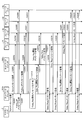
- FIG. 28 is a sequence diagram of time synchronization processing according to the fourth embodiment.
- the master node 2 periodically transmits a Sync message (step S2801).
- the message detection unit 117 detects whether it is a PTP message to be transferred with the highest priority. Since the Sync message is a PTP message transferred with the highest priority, it is directly transferred by the transfer control unit 419 to the dedicated output queue 114 of the input / output port 410 to which the destination node is connected, and the message is immediately output to the slave node 3. (Step S2802 to Step S2804).
- the data is transferred to the dedicated output queue 114 of the input / output ports 410b, 410c, 410d to which the slave nodes 3a, 3b, 3c are connected.
- the PTP message transferred with the highest priority is directly transferred to the dedicated output queue 114, so that the waiting time in the input queue 112 and the waiting time in the output queue 113 do not occur. For this reason, the message retention time in the network switch 400 is reduced, and the time synchronization accuracy between the master node 2 and the slave node 3 is improved.
- Messages other than the PTP message transferred with the highest priority are sent to the input queue 112 of the received input / output port 410, and the message of the input / output port 410 to which the destination node is connected together with the previously sent message. Wait for the order of transfer to the output queue 113.
- the master node 2 transmits a Follow_Up message following the Sync message (step S2805).
- the network switch 400 that has received the Follow_Up message detects that the PTP message is transferred with the highest priority by the message detection unit 117. As a result, the Follow_Up message is transferred with the highest priority as in the Sync message (steps S2806 to S2808).
- the network switch 400 refers to the port state storage unit 423 and detects the input / output port 410 to which the slave node 3 is connected. Then, the start time for starting the transmission of the Delay_Req message is calculated for each of the slave nodes 3a, 3b, 3c connected to each detected input / output port 410 (step S2809). At this time, the network switch 400 sets the start time of the Delay_Req start message to be transmitted to each of the slave nodes 3a, 3b, and 3c to a different time. For example, the start times of the Delay_Req start messages transmitted to the slave nodes 3a, 3b, and 3c are set to “0 milliseconds”, “10 milliseconds”, and “20 milliseconds”, respectively.
- the network switch 400 sets the calculated start time in the Delay_Req start message of each slave node 3 (step S2810) and transmits it to each slave node 3 (steps S2811 to S2813).
- the slave node 3a receives the Delay_Req start message, and the protocol processing unit 24 detects the message. Further, the protocol processing unit 24 reads the start time of the PTP body 431 of the Delay_Req start message, and transmits the Delay_Req message after the read start time (step S2814). In the above example, since the start time is “0 milliseconds”, the slave node 3a transmits the Delay_Req message immediately after receiving the Delay_Req start message.
- the slave nodes 3b and 3c receive the Delay_Req start message, and after the start time specified by the Delay_Req start message has elapsed, transmit the Delay_Req message (steps S2816 and S2818).
- the network switch 400 that has received the Delay_Req message detects by the message detection unit 117 that the message is a PTP message that is transferred with the highest priority. As a result, the Delay_Req message is preferentially transferred to the master node 2 in the same manner as the Sync message.
- the slave nodes 3b and 3c transmit the Delay_Req message 10 milliseconds and 20 milliseconds after receiving the Delay_Req start message, respectively.
- Each Delay_Req message is similarly transferred to the master node 2.
- the slave node 3 that does not need to transmit the Delay_Req message transmits a Delay_Req end message instead of the Delay_Req message.
- the master node 2 transmits the Delay_Resp message to each slave node 3 after receiving the Delay_Req message of each slave node 3.
- the network switch 400 that has received the Delay_Resp message detects by the message detection unit 117 that the message is a PTP message to be transferred with the highest priority. As a result, the Delay_Resp message is transferred to the slave node 3 with the highest priority (step S2815, step S2817, step S2819).
- the message for time synchronization is directly transferred to the dedicated output queue, and the message input to the dedicated output queue is transmitted to the destination node with the highest priority.
- the residence time of the message for time synchronization in a relay apparatus can be made constant.
- the relay device it is possible to transmit a message requesting to transmit a time synchronization message to each of a plurality of slave nodes at different timings. Thereby, it can avoid receiving the message for time synchronization which each slave node transmitted simultaneously.
- the relay device according to the fifth embodiment is connected to a slave node via another relay device. Then, the relay device according to the fifth embodiment transmits a message (Delay_Req start message) requesting to transmit a time synchronization message (Delay_Req message) to a slave node connected via another relay device. Sends with priority. Then, after receiving a Delay_Req message corresponding to the Delay_Req start message from a slave node connected via another relay device, a Delay_Req start message is transmitted to the directly connected slave node.
- FIG. 29 is a diagram illustrating a configuration example of a communication system including a network switch 500 which is a relay device according to the fifth embodiment.
- the communication system according to the fifth embodiment includes network switches 500a and 500b, a master node 2, and slave nodes 3d, 3e, 3f, and 3g. Since the network switches 500a and 500b have the same configuration, they may be simply referred to as the network switch 500 below.
- Master node 2 slave nodes 3d and 3e, and network switch 500b are connected to network switch 500a.
- the slave node 3f and the slave node 3g are connected to the network switch 500b. Since the internal configurations of the master node 2 and the slave node 3 are the same as those in the fourth embodiment, description thereof is omitted.
- FIG. 30 is a block diagram illustrating an example of a configuration of the network switch 500 according to the fifth embodiment.
- the network switch 500 includes an address storage unit 122, a port state storage unit 523, an input / output port 410, a clock unit 101, a CPU 102, a protocol processing unit 505, and a transmission determination unit 506. It is equipped with.
- Each component is connected by an internal bus 131 and transmits / receives data to / from each other via the internal bus 131.
- the fifth embodiment is different from the fourth embodiment in that a data structure of the port state storage unit 523, a function of the protocol processing unit 505, and a transmission determination unit 506 are added.
- Other configurations and functions are the same as those in FIG. 20, which is a block diagram showing the configuration of the network switch 400 according to the fourth embodiment.
- the port state storage unit 523 has a field for storing the number of slave nodes 3 connected to the other network switch 500 when the input / output port 410 to which the other network switch 500 is connected exists.
- FIG. 31 is a diagram illustrating an example of a data structure of data stored in the port state storage unit 523.
- the entry of the port state storage unit 523 includes a port number, a port state, and the number of nodes.
- switch is set as the port state of the input / output port 410 to which the other network switch 500 is connected. Further, the number of nodes holds the number of slave nodes 3 connected to the subordinate when the port state is “switch”.
- the protocol processing unit 505 executes various processes conforming to PTP in the same manner as the protocol processing unit 405 of the fourth embodiment. Also, the protocol processing unit 505 generates a Delay_Req start message and transmits it to the slave node 3. At this time, if there is an entry whose port status is “switch” in the port status storage unit 523, the protocol processing unit 505 gives priority to the other network switch 500 connected to the corresponding input / output port 410. A Delay_Req start message is transmitted to.
- the transmission determination unit 506 determines that the Delay_Req message has been transmitted from all the slave nodes 3 according to the transmitted Delay_Req start message.
- the protocol processing unit 505 transmits a Delay_Req start message to the slave node 3 that is directly connected.
- FIG. 27 is a flowchart showing the overall flow of the relay process in the fourth embodiment, and a description thereof will be omitted.
- the network switch 500 periodically transmits a PTP management request message, and acquires the port state (master or slave) for each node.
- the network switches 500a and 500b each transmit a PTP management request message and acquire the port status of each port. Since the network switch 500b does not have an appropriate port state, an appropriate PTP management response message is not transmitted to the network switch 500a.
- the network switch 500a further investigates the input / output port 410 to which the network switch 500b is connected.
- the network switch 500a transmits an extended PTP management request message to the network switch 500b. Since this is an extension of PTP, a value not assigned by PTP is set in the management ID of this PTP management request message.
- the PTP management response message for this PTP management request message is extended to include the number of subordinate nodes field.
- the number of subordinate nodes is the total number of nodes including those connected in cascade, connected to the network switch 500b.
- the network switch 500a detects the presence of the network switch 500b and detects the number of subordinate nodes. In the case of the configuration as shown in FIG. 29, it is detected that the number of subordinate nodes is two. If another network switch 500c is connected to the network switch 500b and four slave nodes 3 are connected to the network switch 500c, the value of the number of nodes is increased by 4 to 6.
- the protocol processing unit 505 reflects the detected value of the number of nodes in the port state storage unit 523.
- FIG. 32 is a sequence diagram of time synchronization processing according to the fifth embodiment.
- the master node 2 periodically transmits a PTP Sync message (step S3201).
- the network switch 500a detects that the message is processed with the highest priority by the message detection unit 117.
- the Sync message is transmitted to the slave nodes 3d, 3e, 3f, and 3g (Steps S3202 to S3206).
- the Follow_Up message to be transmitted is similarly transmitted to each slave node 3 (steps S3207 to S3212).
- the network switch 500a refers to the port state storage unit 523, and sequentially transmits a Delay_Req start message to the input / output port 410 to which the network switch 500b and the slave nodes 3d and 3e are connected.
- the start time of the Delay_Req start message is all set to zero seconds, but is first transmitted to the network switch 500b (steps S3213 and S3214).
- the network switch 500b After receiving the Delay_Req start message, the network switch 500b immediately transmits the Delay_Req start message to the slave nodes 3f and 3g (Steps S3215 and S3216).
- the start time of the Delay_Req start message is set to zero seconds for the slave node 3f and 10 milliseconds for the slave node 3g.
- the slave nodes 3f and 3g that have received the Delay_Req start message transmit the Delay_Req message to the master node 2 after the start time (steps S3217 and S3219).
- the network switch 500b that has received the Delay_Req message transfers the message to the network switch 500a with the highest priority.
- the network switch 500a that has received the Delay_Req message detects the Delay_Req message and further transfers it to the master node 2.
- the transmission determination unit 506 of the network switch 500a counts the total number of received Delay_Req messages or Delay_Req end messages from the number of nodes in the port state storage unit 523, and the counted value is equal to the number of nodes in the port state storage unit 523. If it is, it is determined that the reception of the Delay_Req message is completed. Then, the protocol processing unit 505 transmits a Delay_Req start message to the slave node 3d (step S3221).
- the slave node 3d After receiving the Delay_Req start message, the slave node 3d immediately transmits a Delay_Req message (step S3222).
- the network switch 500a that has processed the Delay_Req message transmits a Delay_Req start message to the slave node 3e (step S3224).
- the slave node 3e transmits a Delay_Req message (step S3225).
- the master node 2 When the master node 2 receives the Delay_Req transmitted from each slave node 3, the master node 2 immediately transmits a Delay_Resp message (step S3218, step S3220, step S3223, step S3226).
- the network switch 500a does not receive the Delay_Req message at the plurality of input / output ports 410 at the same time. For this reason, even when the highest priority processing for always transferring a predetermined PTP message with the highest priority is executed, the received PTP messages do not collide and the stay time does not vary.
- a Delay_Req start message when a Delay_Req start message is transmitted to a plurality of directly connected slave nodes 3, after receiving a Delay_Req message corresponding to the Delay_Req start message transmitted to one slave node 3, A Delay_Req start message was transmitted to the slave node 3.
- a Delay_Req start message in which different start times are set may be simultaneously transmitted to a plurality of slave nodes 3 by the same method as in the fourth embodiment.
- the collision of the received PTP messages is the same as in the fourth embodiment.
- the residence time can be made constant.
- an internal bus to which a protocol processing unit and a CPU are connected includes traffic on Ethernet (registered trademark), instruction data executed by the CPU, monitoring control information of each hardware constituting the device, and the like. It is very difficult to control the flow and data flow.
- a bus for transferring a message for controlling the data flow and minimizing the residence time is made independent from the internal bus as described above.
- this priority bus only the PTP messages transferred with the highest priority are transferred so that the residence time of these messages can be easily controlled.
- FIG. 33 is a block diagram illustrating an example of the configuration of the network switch 600 according to the sixth embodiment.
- the network switch 600 includes an address storage unit 122, a port state storage unit 423, input / output ports 610a, 610b, 610c, and 610d (hereinafter referred to as input / output ports 610), a clock unit 101, and the like.
- a CPU 102 and a protocol processing unit 405 are provided.
- Each component is connected by an internal bus 131 and transmits / receives data to / from each other via the internal bus 131.
- the input / output ports 610 are connected to each other by a priority bus 632 and transmit / receive a PTP message to be transmitted with priority via the priority bus 632.
- the priority bus 632 as described above is added and the function of the input / output port 610 is different from that of the fourth embodiment.
- Other configurations and functions are the same as those in FIG. 20, which is a block diagram showing the configuration of the network switch 400 according to the fourth embodiment.
- the input / output port 610 is a port to which a cable 132 for connecting to each node is connected.
- FIG. 34 is a block diagram illustrating an example of a detailed configuration of the input / output port 610.
- the input / output port 610 includes a PHY unit 111, an input queue 112, an output queue 113, a dedicated output queue 614, a connection detection unit 115, a message detection unit 117, and a transmission control unit 418.
- the input queue 112, the output queue 113, the connection detection unit 115, the transfer control unit 619, and the message determination unit 420 are connected by the internal bus 131, and the dedicated output queue 614 and the message detection.
- the point that the unit 117 and the transfer control unit 619 are connected by the priority bus 632 is different from the fourth embodiment.
- the functions of the dedicated output queue 614 and the transfer control unit 619 are different from those in the fourth embodiment.
- Other configurations and functions are the same as those shown in FIG. 24, which is a block diagram showing the configuration of the input / output port 410 according to the fourth embodiment.
- the transfer control unit 619 controls to transfer the PTP message transferred with the highest priority to the dedicated output queue 614 of all the other input / output ports 610 via the priority bus 632 in the fourth embodiment. Different from the transfer control unit 419.
- the dedicated output queue 614 determines whether or not the destination address of the transferred PTP message matches the address of the node connected to the corresponding input / output port 610, and the transferred PTP message is transferred only when they match. It differs from the dedicated output queue 114 of the fourth embodiment in that a function for storing is added.
- FIG. 35 is a flowchart illustrating an overall flow of relay processing in the sixth embodiment.
- steps S3501 to S3503 are the same as steps S2701 to S2703 in the network switch 400 according to the fourth embodiment, the description thereof is omitted.
- step S3503 If the PTP message is transferred with the highest priority (step S3503: YES), the transfer control unit 619 transfers the PTP message to the dedicated output queue 614 of all the other input / output ports 610 (step S3504).
- the dedicated output queue 614 of the input / output port 610 to which the PTP message has been transferred confirms the destination address of the PTP message and stores the transferred PTP message if it matches the address of the node connected to the input / output port 610. .
- steps S3505 to S3508 are the same as steps S2705 to S2708 in the network switch 400 according to the fourth embodiment, the description thereof is omitted.
- the PHY unit 111 converts the message into digital information and passes it to the input queue 112 and the message detection unit 117.
- the message detection unit 117 determines whether or not the currently received message is a PTP message to be transferred with the highest priority, and whether or not the message format matches the PTP message to be transferred with the highest priority. Judge by examining. If the PTP message is transferred with the highest priority, the transfer control unit 619 transfers the message to the input / output port 610 to which the message is to be transmitted through the priority bus 632. On the other hand, the transfer control unit 619 instructs the input queue 112 to discard the message.
- the transfer control unit 619 of the input / output port 610 a transfers the received message to the dedicated output queue 614 of all other input / output ports 610 via the priority bus 632.
- the dedicated output queue 614 of each input / output port 610 confirms the destination address of the message transferred on the priority bus 632, determines whether or not to capture the message, and captures the message when it is determined to capture.
- the transmission control unit 418 immediately outputs the message taken into the dedicated output queue 614 to the PHY unit 111.
- the PHY unit 111 converts the passed bit string into a signal in a format based on the Ethernet (registered trademark) specification, and sends the signal to the cable 132.
- stagnation may occur in the following two cases. (1) When a PTP message transferred with the highest priority is sent from a certain input / output port 610 (for example, input / output port 610a) to the priority bus 632, priority is given by another input / output port 610 (for example, input / output port 610b). When a message is sent to the bus 632. (2) When a message is sent from the output queue 113 when a message is sent from the dedicated output queue 614 to the cable 132.
- the stay is transferred from the master node 2 to the slave node 3 or transferred from the slave node 3 to the master node 2. This can be avoided by controlling so that it does not arrive.
- the PTP message transferred by the master node 2 since the master node 2 is one in the system and the sequence starts from the master node 2, the PTP message transferred by the master node 2 with the highest priority ( This can be avoided by controlling the transmission interval of the Sync message or the like. That is, if the master node 2 sends out the next Sync message after the series of sequences started by the Sync message sent in the past is completed, the stay can be avoided.
- the waiting time until the slave node 3 responds is specified by setting the start time in the Delay_Req start message.
- FIG. 36 is a diagram illustrating an example of processing time allocated to the dedicated output queue 614 and the output queue 113. As shown in FIG. 36, a period of time during which only the PTP message to be transferred with the highest priority can be sent to the cable 132 is periodically provided.
- 100 ⁇ sec in 1 ms is a time in which only the PTP message transferred with the highest priority can be transmitted.
- This periodic structure is created by the transmission control unit 418.
- the transmission control unit 418 calculates the time required to send the message to the cable 132. This time can be calculated from the message length and the physical speed of the cable 132. Thereafter, the transmission control unit 418 calculates a time when the message transmission ends when the message transmission starts at that time. Then, based on this time, the transmission control unit 418 determines whether or not the transmission is completed by the start of the time when only the PTP message to be transferred with the highest priority can be transmitted when the message is transmitted at the present time.
- the transmission control unit 418 keeps the output queue 113 from the output queue 113 until the time when only the PTP message transferred with the highest priority can be transmitted so as not to prevent the transmission of the PTP message transferred with the highest priority. Wait for message transmission.
- the priority bus for transferring the message to be transferred with the highest priority can be made independent of the internal bus through which other data flows. As a result, it is possible to easily realize control that makes the stay time of a message transferred with the highest priority constant.
- the relay program executed by the relay device is an installable or executable file, such as a CD-ROM (Compact Disk Read Only Memory), a flexible disk (FD), It is recorded on a computer-readable recording medium such as a CD-R (Compact Disk Recordable) or DVD (Digital Versatile Disk) and provided as a computer program product.
- a CD-ROM Compact Disk Read Only Memory
- FD flexible disk
- a computer-readable recording medium such as a CD-R (Compact Disk Recordable) or DVD (Digital Versatile Disk) and provided as a computer program product.
- the relay program executed by the relay device according to the first to sixth embodiments is stored on a computer connected to a network such as the Internet, and is provided by being downloaded via the network. May be.
- the relay program executed by the relay device according to the first to sixth embodiments may be provided or distributed via a network such as the Internet.
- relay programs of the first to sixth embodiments may be provided by being incorporated in advance in a ROM or the like.
- the present invention is not limited to the above-described embodiment as it is, and can be embodied by modifying the constituent elements without departing from the scope of the invention in the implementation stage.
- various inventions can be formed by appropriately combining a plurality of constituent elements disclosed in the above embodiments. For example, some components may be deleted from all the components shown in the embodiment. Furthermore, constituent elements over different embodiments may be appropriately combined.
Landscapes
- Engineering & Computer Science (AREA)
- Computer Networks & Wireless Communication (AREA)
- Signal Processing (AREA)
- Small-Scale Networks (AREA)
- Synchronisation In Digital Transmission Systems (AREA)
Abstract
第2通信装置を宛先とし、送信時刻を含む第1同期メッセージを第1通信装置から受信する受信部を備えた入出力ポート110aと、第1同期メッセージを第2通信装置に送信するまでの滞留時間を算出する算出部103と、第1同期メッセージを受信してから滞留時間が経過した後に第1同期メッセージを第2通信装置に送信する入出力ポート110a内の送信制御部と、第1同期メッセージに応じて第1通信装置を宛先として送信され、送信時刻を含む第2同期メッセージを第2通信装置から受信する受信部を備えた入出力ポート110b~dと、第2同期メッセージを受信してから、対応する第1同期メッセージに対して算出された滞留時間が経過した後に第2同期メッセージを第1通信装置に送信する入出力ポート110b~d内の送信制御部と、を備える。
Description
本発明は、メッセージを中継する中継装置およびプログラムに関する。
IEEE1588(非特許文献1)では、高精度な時刻同期を行うためのプロトコルであるPTP(Precision Time Protocol)が定義されている。PTPでは、マスターノードとスレーブノードの時刻を同期するために、スレーブノードは、マスターノードから定期的に送信されるSyncメッセージの送信時刻および受信時刻と、スレーブノードからマスターノードに送信するDellay_Reqメッセージの送信時刻および受信時刻とから、マスターノードに対する時刻のずれを求める。
しかしながら、IEEE1588では、マスターノードからスレーブノードにメッセージを送信する場合と、スレーブノードからマスターノードにメッセージを送信する場合とで、伝送遅延が等しいと仮定している。このため、実際には両者の伝送遅延が等しくない場合は、時刻の計算時に誤差が生じ、時刻同期精度が下がるという問題があった。例えば、マスターノードとスレーブノードとの間にネットワークスイッチ等の別のノードが存在し、当該ノードがメッセージを中継している場合は、ノード内のキューイング遅延等が生じるため、伝送遅延が等しくならない場合がある。
本発明は、上記に鑑みてなされたものであって、メッセージを中継する通信装置間の時刻同期を高精度に実行可能とする装置およびプログラムを提供することを目的とする。
上述した課題を解決し、目的を達成するために、本発明は、第1通信装置と第2通信装置との間で送受信されるメッセージを中継する中継装置であって、前記第2通信装置を宛先とし、送信時刻を含む第1同期メッセージを前記第1通信装置から受信する第1受信部と、前記第1同期メッセージを前記第2通信装置に送信するまでに滞留する時間の予測値である第1滞留時間を算出する算出部と、前記第1同期メッセージを受信してから前記第1滞留時間が経過した後に前記第1同期メッセージを前記第2通信装置に送信する第1送信制御部と、前記第1同期メッセージに応じて前記第1通信装置を宛先として送信され、送信時刻を含む第2同期メッセージを前記第2通信装置から受信する第2受信部と、前記第2同期メッセージを受信してから、対応する前記第1同期メッセージに対して算出された前記第1滞留時間が経過した後に前記第2同期メッセージを前記第1通信装置に送信する第2送信制御部と、を備えることを特徴とする。
また、本発明は、第1通信装置と第2通信装置との間で送受信されるメッセージを中継する中継装置であって、前記第2通信装置を宛先とし、送信時刻を含む第1同期メッセージを前記第1通信装置から受信する第1受信部と、前記第1同期メッセージを前記第2通信装置に送信するまでに滞留する時間の予測値である第1滞留時間を算出する第1算出部と、算出された前記第1滞留時間を前記第1同期メッセージに付加し、前記第1同期メッセージを受信してから前記第1滞留時間が経過した後に、前記第1滞留時間を付加した前記第1同期メッセージを前記第2通信装置に送信する第1送信制御部と、前記第1同期メッセージに応じて前記第1通信装置を宛先として送信され、送信時刻を含む第2同期メッセージを前記第2通信装置から受信する第2受信部と、前記第2同期メッセージを前記第1通信装置に送信するまでに滞留する時間の予測値である第2滞留時間を算出する第2算出部と、算出された前記第2滞留時間を前記第2同期メッセージに付加し、前記第2同期メッセージを受信してから前記第2滞留時間が経過した後に、前記第2滞留時間を付加した前記第2同期メッセージを前記第1通信装置に送信する第2送信制御部と、を備えることを特徴とする。
また、本発明は、第1通信装置と第2通信装置との間で送受信されるメッセージを中継する中継装置であって、FIFO(First In First Out)方式でn個(nは2以上の整数)のメッセージを記憶可能な記憶部と、前記記憶部からFIFO方式でメッセージを取得し、取得したメッセージで指定された宛先に、取得したメッセージを送信する送信制御部と、前記第2通信装置を宛先とし、送信時刻を含む第1同期メッセージを前記第1通信装置から受信する第1受信部と、前記第1同期メッセージに応じて前記第1通信装置を宛先として送信され、送信時刻を含む第2同期メッセージを前記第2通信装置から受信する第2受信部と、前記第1同期メッセージおよび前記第2同期メッセージを、前記記憶部のFIFO方式でn番目に出力される位置に保存する保存部と、を備えることを特徴とする。
また、本発明は、第1通信装置と第2通信装置との間で送受信されるメッセージを中継する中継装置であって、前記第2通信装置を宛先とするメッセージを前記第1通信装置から受信する第1受信部と、受信されたメッセージが、送信時刻を含む第1同期メッセージであるか否かを判定する第1メッセージ判定部と、前記第1同期メッセージであると判定されたメッセージを記憶する第1記憶部と、前記第1同期メッセージでないと判定されたメッセージを記憶する第2記憶部と、前記第1記憶部に記憶されたメッセージを、前記第2記憶部に記憶されたメッセージより優先して前記第2通信装置に送信する第1送信制御部と、前記第1通信装置を宛先とするメッセージを前記第2通信装置から受信する第2受信部と、受信されたメッセージが、前記第1同期メッセージに応じて送信され、送信時刻を含む第2同期メッセージであるか否かを判定する第2メッセージ判定部と、前記第2同期メッセージであると判定されたメッセージを記憶する第3記憶部と、前記第2同期メッセージでないと判定されたメッセージを記憶する第4記憶部と、前記第3記憶部に記憶されたメッセージを、前記第4記憶部に記憶されたメッセージより優先して前記第1通信装置に送信する第2送信制御部と、を備えることを特徴とする。
また、本発明は、上記装置で実行することができるプログラムである。
本発明によれば、メッセージを中継する通信装置間の時刻同期を高精度に実行できるという効果を奏する。
以下に添付図面を参照して、この発明にかかる中継装置および中継プログラムの最良な実施の形態を詳細に説明する。
(第1の実施の形態)
第1の実施の形態にかかる中継装置は、通信装置であるIEEE1588のマスターノードおよびスレーブノードに接続され、マスターノードから送信される時刻同期用のメッセージと、スレーブノードから送信される時刻同期用のメッセージとに対し、中継装置内での滞留時間を一致させるように制御する。
第1の実施の形態にかかる中継装置は、通信装置であるIEEE1588のマスターノードおよびスレーブノードに接続され、マスターノードから送信される時刻同期用のメッセージと、スレーブノードから送信される時刻同期用のメッセージとに対し、中継装置内での滞留時間を一致させるように制御する。
図1は、第1の実施の形態の中継装置であるネットワークスイッチ100を含む通信システムの構成例を示す図である。図1に示すように、第1の実施の形態の通信システムは、ネットワークスイッチ100と、マスターノード2と、スレーブノード3とを備えている。
マスターノード2およびスレーブノード3は、イーサネット(登録商標)ケーブルなどのケーブルにより、ネットワークスイッチ100に接続されている。以下では、マスターノード2およびスレーブノード3は、イーサネット(登録商標)に準拠したケーブルで接続されているものとして説明する。マスターノード2およびスレーブノード3は、IEEE1588を実装しており、それぞれIEEE1588で規定されたマスタースレーブ階層のマスターおよびスレーブとして動作する。
本実施の形態の通信システムは、原子時計内蔵マスタークロックをマスターノード2、遮断機へトリップ信号を送信する保護リレー装置等をスレーブノード3とする変電所システムに適用できる。トリップ信号は、複数の遮断機へ高い時刻制度により同時に送信されることが要求されるため、これらの機器は時刻が同期されている必要がある。
なお、適用可能なシステムはこれに限られるものではない。また、中継装置はネットワークスイッチに限られるものではなく、時刻同期用のメッセージを中継できるものであれば、ルータなどの従来から用いられているあらゆる中継装置に適用できる。また、以下では、時刻同期のためのプロトコルとしてIEEE1588で定義されるPTPを用いる場合を例に説明する。この場合の時刻同期用のメッセージを以下ではPTPメッセージという。
図2は、ネットワークスイッチ100の内部構成の一例を示すブロック図である。ネットワークスイッチ100は、対応記憶部121と、アドレス記憶部122と、入出力ポート110a、110b、110c、110dと、クロック部101と、CPU102と、算出部103と、を備えている。各構成部は、内部バス131により接続され、内部バス131を介して相互にデータを送受信する。
対応記憶部121は、マスターノード2からスレーブノード3に送信されたPTPメッセージであるSyncメッセージに含まれる所定のパラメータと、当該Syncメッセージを送信したときの滞留時間を特定可能な情報とを対応づけて記憶する。図3は、対応記憶部121に記憶されるデータのデータ構造の一例を示す図である。図3に示すように、対応記憶部121は、1つのエントリに、イーサネット(登録商標)ヘッダ(以下、イーサヘッダという)の送主(送信元)アドレスと、イーサヘッダの宛先アドレスと、PTPヘッダのシーケンス番号と、メッセージの受信時刻と、メッセージの送信時刻とを含んでいる。
なお、同図では、送信時刻と受信時刻とを保存する例が示されているが、滞留時間を特定可能な情報はこれに限られるものではない。例えば、滞留時間自体を保存するように構成してもよい。
アドレス記憶部122は、入出力ポート110a、110b、110c、110dに接続されたノードのアドレスを記憶する。この情報により、メッセージを転送すべきノードが接続されたポートを特定することができる。
なお、対応記憶部121およびアドレス記憶部122は、HDD(Hard Disk Drive)、光ディスク、メモリカード、RAM(Random Access Memory)などの一般的に利用されているあらゆる記憶媒体により構成することができる。
クロック部101は、クロック信号を発生させる。CPU102は、ネットワークスイッチ100内で実行される各種処理を制御するプロセッサである。
入出力ポート110a、110b、110c、110dは、各ノードに接続するためのケーブルが接続されるポートである。なお、入出力ポート110a、110b、110c、110dはそれぞれ同様の構成を備えるため、以下では単に入出力ポート110という場合がある。また、入出力ポート110の個数は4に限られるものではない。また、以下では、マスターノード2およびスレーブノード3が、それぞれ入出力ポート110aおよび入出力ポート110bに接続されているものとして説明する。
図4は、入出力ポート110の詳細構成の一例を示すブロック図である。図4に示すように、入出力ポート110は、PHY(PHYsical layer)部111と、入力キュー112と、出力キュー113と、専用出力キュー114と、接続検出部115と、時刻検出部116と、メッセージ検出部117と、送信制御部118と、転送制御部119と、を備えている。これらは、内部バス131により接続され、相互にデータのやり取りが可能である。
PHY部111は、OSI参照モデルの物理層に関連する処理を実行する。PHY部111は、さらに詳細な構成として、受信部111aと、送信部111bとを備えている。受信部111aは、ケーブル132からメッセージを受信する。具体的には、受信部111aは、ケーブル132からメッセージを表す電気信号が到着すると、電気信号をディジタル情報に変換し、メッセージ検出部117に渡す。送信部111bは、ケーブル132に対してメッセージを送信する。具体的には、送信部111bは、送信すべきメッセージを表すビット列を、イーサネット(登録商標)の仕様に準拠した形式の信号に変換し、ケーブル132に送出する。
入力キュー112は、受信したメッセージを一時的に記憶するキューである。入力キュー112は、複数のメッセージを一時的に記憶できる。以下では、入力キュー112に記憶可能なメッセージの個数を表す最大長をQ_imaxと表す。
出力キュー113は、ケーブル132に出力するメッセージを一時的に記憶するキューである。出力キュー113は、予め定められたクロック(以下、クロックCとする)ごとに、記憶しているメッセージを出力する。出力キュー113は、複数のメッセージを一時的に記憶できる。以下では、出力キュー113に記憶可能なメッセージの個数を表す最大長をQ_omaxと表す。なお、入力キュー112の最大長Q_imaxと、出力キュー113の最大長Q_omaxは固定値とする。
専用出力キュー114は、予め定められたPTPメッセージを一時的に記憶するキューである。専用出力キュー114は、算出部103により算出された送信予定時刻に、記憶したメッセージを出力するように送信制御部118により制御される。
接続検出部115は、ケーブル132を介してノードが接続されているか否かを検出する。例えば、接続検出部115は、ケーブル132を介してノードがアクティブであることを表す所定の信号を受信したか否かにより、ノードが接続されているか否かを検出する。接続検出部115は、ケーブル132が接続されかつノードがアクティブの場合には、接続状態としてオン情報を保持する。また、接続検出部115は、ケーブル132が接続されていない場合、または、ノードがアクティブでない場合には、接続状態としてオフ情報を保持する。
上述のようにマスターノード2およびスレーブノード3が、それぞれ入出力ポート110aおよび入出力ポート110bに接続されている場合は、入出力ポート110aおよび入出力ポート110bの接続検出部115は、オン情報を保持している。一方、入出力ポート110cおよび入出力ポート110dは、ノードが接続されていないため、オフ情報を保持している。
時刻検出部116は、メッセージを受信した時刻(受信時刻)を検出する。例えば、時刻検出部116は、クロック部101から時刻情報を受け取ることにより、メッセージの受信時刻を検出し、検出した受信時刻を保持する。
メッセージ検出部117は、受信されたメッセージの種類を検出する。具体的には、メッセージ検出部117は、イーサヘッダのタイプとPTPメッセージのPTPヘッダのメッセージタイプとを参照することにより、メッセージの種類を検出する。
図5は、受信されるPTPメッセージのメッセージ形式の一例を示す図である。図5に示すように、PTPメッセージは、イーサヘッダ41と、PTPヘッダ42と、PTPボディ43と、送信時刻タグ44とから構成される。PTPメッセージは、システムによっては、UDP/IP通信のパケットとして運ばれる場合がある。本実施の形態では、イーサネット(登録商標)により運ばれため、イーサヘッダ41が付加されている。
イーサヘッダ41は、宛先アドレス41aと、送主アドレス41bと、タイプ41cとから構成されている。宛先アドレス41aは、宛先のノードのMACアドレス、ブロードキャストアドレス、およびマルチキャストアドレスなどが割り当てられる。送主アドレス41bは、送主のノードのMACアドレスが割り当てられる。タイプ41cは、ペイロードの内容を表す。PTPの場合は、タイプ41cに「0x8807」が割り当てられる。
PTPヘッダ42は、PTPで定められたパラメータを格納するヘッダである。図6は、PTPヘッダ42の詳細な構成の一例を示す図である。図6に示すように、PTPヘッダ42は、メッセージタイプ42aと、バージョン42bと、メッセージ長42cと、ドメイン番号42dと、フラグフィールド42eと、コレクションフィールド42fと、ソースポートID42gと、シーケンスID42hと、制御フィールド42iと、ログメッセージ間隔42jとから構成される。
メッセージタイプ42aは、PTPメッセージの種類により異なる値が割り当てられる。バージョン42bは、PTPプロトコルのバージョンを表す。メッセージ長42cは、PTPヘッダを含むメッセージの長さである。ドメイン番号42dは、時刻を同期する範囲を表す識別子である。フラグフィールド42eは、メッセージによって与えられる詳細の情報である。コレクションフィールド42fは、マスターノード2およびスレーブノード3以外のIEEE1588ノードにメッセージが滞留した時間である。ソースポートID42gは、IEEE1588ノードの送主の送信ポートの識別子を示す。シーケンスID42hは、PTPメッセージの識別子を示す。制御フィールド42iは、メッセージによって異なる値が割り当てられる識別子である。ログメッセージ間隔42jは、メッセージによって役割が異なる。
図5に戻り、PTPボディ43は、PTPメッセージの種類によって構成が変更される。図7~図9は、PTPボディ43の一例を示す図である。
図7は、PTPメッセージがSyncメッセージである場合のPTPボディ43の構造を示す。SyncメッセージのPTPボディ431は、送主タイムスタンプにより構成される。送主タイムスタンプは、Syncメッセージがマスターノード2から送信された概算の時刻を表す。なお、Syncメッセージの場合、イーサヘッダ41の宛先アドレス41aはマルチキャストアドレスとなり、PTPヘッダ42のメッセージタイプ42aは「0」となる。
なお、Delay_ReqメッセージのPTPボディは、SyncメッセージのPTPボディ431と同じ構成であり、送主タイムスタンプが保持可能である。Delay_Reqメッセージの場合、イーサヘッダ41の宛先アドレス41aにはマスターノード2のMACアドレス、送主アドレス41bにはスレーブノード3のMACアドレス、PTPヘッダ42のメッセージタイプ42aの値には「1」が設定される。
図8は、PTPメッセージがFollow_Upメッセージである場合のPTPボディ43の構造を示す。Follow_UpメッセージのPTPボディ432は、精密な送主タイムスタンプにより構成される。精密な送主タイムスタンプは、Syncメッセージが実際に送信された時刻である。Follow_Upメッセージの場合、イーサヘッダ41の宛先アドレス41aにはマルチキャストアドレス。送主アドレス41bにはマスターノード2のMACアドレス、タイプ41cには「0x0087」、PTPヘッダ42のメッセージタイプ42aの値には「8」が設定される。
図9は、PTPメッセージがDelay_Respメッセージである場合のPTPボディ43の構造を示す。Delay_RespメッセージのPTPボディ433は、受信タイムスタンプと要求ポートIDとにより構成される。受信タイムスタンプは、Delay_Reqメッセージを受信した時刻が保持されている。要求ポートIDは、Delay_Reqメッセージを送信した送信先のポートIDが保持されている。Delay_Respメッセージはユニキャストである。Delay_Respメッセージの場合、イーサヘッダの送主アドレスにはマスターノード2のMACアドレス、宛先アドレスにはスレーブノード3のMACアドレス、PTPヘッダ42のメッセージタイプ42aの値には「9」が設定される。
図4に戻り、メッセージ検出部117は、このように構成されたメッセージの各ヘッダ等を参照することによりメッセージの種類を検出する。例えば、イーサヘッダ41のタイプ41cが「0x8807」で、かつPTPヘッダのメッセージタイプが「0」の場合は、メッセージ検出部117は、受信したメッセージがSyncメッセージであることを検出する。この場合、メッセージ検出部117は、Syncメッセージのイーサヘッダ41の送主アドレス41bと、イーサヘッダ41の宛先アドレス41aと、PTPヘッダ42のシーケンスID42hと、時刻検出部116により検出された受信時刻とを含むエントリを作成し、対応記憶部121に追加する。
送信制御部118は、出力キュー113および専用出力キュー114に記憶されているメッセージの送信タイミングを制御する。例えば、送信制御部118は、クロックCごとに、出力キュー113に記憶されているメッセージを、PHY部111を介してケーブル132に送信するように制御する。また、送信制御部118は、専用出力キュー114に記憶されているメッセージを、算出部103により算出された送信予定時刻にPHY部111を介してケーブル132に送信するように制御する。
転送制御部119は、入力キュー112に記憶されているメッセージを、他の入出力ポート110の出力キュー113に転送する処理を制御する。例えば、転送制御部119は、クロックCごとに、入力キュー112に記憶されているメッセージの1つを取得し、内部バス131を介して、取得したメッセージの宛先となるノードが接続された入出力ポート110の出力キュー113に転送する。
図2に戻り、算出部103は、入出力ポート110から入力されたメッセージがネットワークスイッチ100内に滞留する時間(滞留時間)の予測値を算出する。具体的には、算出部103は、以下のアルゴリズムにしたがって滞留時間を見積もる。
まず、ネットワークスイッチ100は、アクティブなノードに接続されたN個の入出力ポート110の入力キュー112および出力キュー113に対して、クロックCごとに、予め定められた順番で巡回してアクセスするものとする。ノードがアクティブか否かは、接続検出部115が保持する接続状態(オン情報かオフ情報か)により判断できる。また、滞留時間の見積り時にアクセスしている入力キュー112を基準とした、滞留時間の見積り対象であるメッセージを受信した入出力ポート110の入力キュー112のアクセスする順番をTとする。なお、TはN以下(T<=N)である。この場合、複数の入力キュー112を所定の順序でアクセスすることにより生じる滞留時間の最大値(最大滞留時間)は、C×(T×Q_imax+Q_omax)となる。
算出部103は、まず、受信されたメッセージが入力キュー112へ送られた時に、出力キュー113への転送用にアクセスされている入力キュー112の位置を検出する。そして、算出部103は、受信されたメッセージが出力するまでに滞留する時間として予測される時間の最大値であるS+C×(T×Q_imax+Q_omax)を滞留時間として算出する。なお、Sは、受信されたメッセージが入力キュー112へ送られる時間として予め定められた値である。
なお、同図に示すように算出部103をCPU102と異なるハードウェア回路により実現する代わりに、CPU102により動作するソフトウェアとして構成してもよい。
次に、このように構成された第1の実施の形態にかかるネットワークスイッチ100による中継処理について図10を用いて説明する。図10は、第1の実施の形態における中継処理の全体の流れを示すフローチャートである。
まず、PHY部111の受信部111aが、マスターノード2またはスレーブノード3から送信されたメッセージを受信する(ステップS1001)。次に、時刻検出部116が、メッセージの受信時刻を検出して保持する(ステップS1002)。次に、メッセージ検出部117が、イーサヘッダのタイプおよびPTPヘッダのメッセージタイプを参照してメッセージの種類を検出する(ステップS1003)。
次に、メッセージ検出部117が、受信したメッセージがSyncメッセージであるか否かを判断する(ステップS1004)。Syncメッセージの場合(ステップS1004:YES)、メッセージ検出部117は、Syncメッセージのイーサヘッダ41の送主アドレス41bと、PTPヘッダ42のシーケンスID42hと、受信時刻とを含むエントリを作成し、対応記憶部121へ追加する(ステップS1005)。次に、算出部103が、Syncメッセージの滞留時間を算出する(ステップS1006)。
Syncメッセージでない場合(ステップS1004:NO)、メッセージ検出部117は、さらに受信したメッセージがDelay_Reqメッセージであるか否かを判断する(ステップS1007)。Delay_Reqメッセージの場合(ステップS1007:YES)、算出部103は、受信されたDelay_Reqメッセージに対応するSyncメッセージがネットワークスイッチ100を通過した際に要した滞留時間を調べる。すなわち、算出部103は、Delay_Reqメッセージのイーサヘッダの送主アドレスと一致する宛先アドレスを有するエントリを対応記憶部121から検索する(ステップS1008)。
そして、算出部103は、検索したエントリの送信時刻と受信時刻との差分であるSyncメッセージの滞留時間を算出する(ステップS1009)。なお、対応記憶部121に滞留時間自体が記憶されている場合は、算出部103は検索したエントリから滞留時間を取得する。また、算出部103は、Delay_Reqメッセージの滞留時間を算出する(ステップS1010)。
次に、算出部103は、Delay_Reqメッセージの滞留時間が、対応するSyncメッセージの滞留時間以下であるか否かを判断する(ステップS1011)。Delay_Reqメッセージの滞留時間が、対応するSyncメッセージの滞留時間以下でない場合(ステップS1011:NO)、算出部103は、受信されたDelay_Reqメッセージを破棄し(ステップS1012)、中継処理を終了する。
Delay_Reqメッセージの滞留時間が、対応するSyncメッセージの滞留時間以下である場合(ステップS1011:YES)、算出部103は、Delay_Reqメッセージの滞留時間を対応するSyncメッセージの滞留時間に一致させる(ステップS1013)。
ステップS1006でSyncメッセージの滞留時間を算出後、または、ステップS1013でDelay_Reqメッセージの滞留時間を算出後、算出部103は、算出した滞留時間をメッセージの受信時刻に加算することにより送信予定時刻を算出し、メッセージの送信時刻タグ44に付加する(ステップS1014)。
次に、算出部103は、送信予定時刻を付加したメッセージを、メッセージを受信した入出力ポート110の入力キュー112に送出する(ステップS1015)。入力キュー112に送出されたメッセージは、別の入出力ポート110の出力キュー113に転送されるまで保持される。転送制御部119は、メッセージが転送される順番となったとき、入力キュー112に保持されたメッセージを、宛先となるノードが接続された入出力ポート110の出力キュー113に転送する(ステップS1016)。転送制御部119は、アドレス記憶部122を参照することにより宛先となるノードが接続された入出力ポート110を決定する。
メッセージが転送された入出力ポート110の送信制御部118は、クロックCごとに、送信するメッセージを出力キュー113から取得する(ステップS1017)。次に、メッセージ検出部117が、ステップS1003と同様の手法により、取得されたメッセージの種類を検出する(ステップS1018)。
次に、メッセージ検出部117が、取得されたメッセージがSyncメッセージまたはDelay_Reqメッセージであるか否かを判断する(ステップS1019)。SyncメッセージまたはDelay_Reqメッセージである場合(ステップS1019:YES)、メッセージ検出部117は、取得されたメッセージを専用出力キュー114に転送する(ステップS1020)。
次に、送信制御部118は、メッセージの送信時刻タグから送信予定時刻を抽出し、定期的にクロック部101から取得した現在時刻と送信時刻とを比較することにより、送信予定時刻に達したか否かを判断する(ステップS1021)。送信予定時刻でない場合(ステップS1021:NO)、送信予定時刻となるまで専用出力キュー114にメッセージが保持される。送信予定時刻である場合(ステップS1021:YES)、送信制御部118は、PHY部111を介して、専用出力キュー114に保持されたメッセージを宛先となるノードに送信する(ステップS1022)。
ステップS1019で、出力キュー113から取得されたメッセージがSyncメッセージまたはDelay_Reqメッセージでないと判断された場合(ステップS1019:NO)、送信制御部118は、PHY部111を介して、取得されたメッセージを宛先となるノードに送信する(ステップS1022)。
次に、送信制御部118は、対応記憶部121のエントリを更新する(ステップS1023)。例えば、Syncメッセージを送信した場合、送信制御部118は、シーケンスID42hが一致するエントリの送信時刻および宛先アドレスとして、メッセージの送信時刻と、宛先のノードのMACアドレスとを追加する。なお、このエントリ以外に同じ送主アドレスおよび宛先アドレスのエントリ(重複エントリ)が存在した場合、送信制御部118は当該重複エントリを削除する。
また、Delay_Reqメッセージを送信した場合、送信制御部118は、送信したDelay_Reqメッセージに対応するSyncメッセージを、イーサヘッダの宛先アドレスと送主アドレスとを用いて対応記憶部121から検索する。Delay_Reqメッセージの送主アドレスとSyncメッセージの宛先アドレス、および、Delay_Reqメッセージの宛先アドレスとSyncメッセージの送主アドレスが一致した場合、送信制御部118は、そのエントリを対応記憶部121から削除する。
上記のような手順により、Syncメッセージの滞留時間と、Syncメッセージに対する応答として送信されるDelay_Reqメッセージの滞留時間とを一致させることができる。すなわち、マスターノード2からスレーブノード3にメッセージを送信する場合と、スレーブノード3からマスターノード2にメッセージを送信する場合とで、伝送遅延を一致させることができる。これにより、これらのメッセージの受信時刻等を用いる時刻同期処理を高精度に実行可能となる。
次に、本実施の形態の通信システムによる時刻同期処理の具体例について説明する。IEEE1588では、マスターノード2からのSyncメッセージおよびFollow_Upメッセージの送信、スレーブノード3からのDelay_Reqメッセージの送信、および、マスターノード2からのDelay_Respメッセージの送信、という手順により、時刻同期処理が実現される。
まず、マスターノード2は、IEEE1588で定義されているPTPのSyncメッセージを定期的に送信する。
マスターノード2から送信されたSyncメッセージは、ネットワークスイッチ100の入出力ポート110aに受信される。メッセージ検出部117は、イーサヘッダ41のタイプ41cが「0x8807」で、かつPTPヘッダのメッセージタイプが「0」であるため、Syncメッセージであることを検出する。次に、算出部103が、Syncメッセージの滞留時間を見積もる。また、算出部103は、算出した滞留時間を受信時刻に加算して送信予定時刻を算出する。そして、算出部103は、算出した送信予定時刻を設定した送信時刻タグ44をSyncメッセージに付加する。
次に、Syncメッセージは、入力キュー112に送られ、別の入出力ポート110bの出力キュー113に転送されるまで保持される。Syncメッセージが転送される順番となったとき、転送制御部119が、アドレス記憶部122を参照して、Syncメッセージのイーサヘッダの宛先アドレス41aに該当する入出力ポート110を検出する。この例では、スレーブノード3が宛先となるため、入出力ポート110bが検出される。したがって、Syncメッセージは、入出力ポート110bの出力キュー113へ転送され、メッセージがスレーブノード3へ送信されるまで保持される。
送信の順番となったとき、メッセージ受信時と同様の手順により、メッセージ検出部117によりメッセージの種類が判定される。この場合はSyncメッセージであることが検出され、専用出力キュー114へ送られる。送信制御部118は、送信時刻タグから送信予定時刻を抽出し、送信予定時刻となるまでSyncメッセージを専用出力キュー114に保持する。送信制御部118は、送信予定時刻となったときにSyncメッセージをスレーブノード3に送信する。
Syncメッセージがスレーブノード3に受信されると、続いて、マスターノード2はFollow_Upメッセージを送信する。
Follow_Upメッセージがネットワークスイッチ100に受信されると、Syncメッセージと同様に、入出力ポート110aの時刻検出部116が、Follow_Upメッセージの受信時刻を検出する。次に、メッセージ検出部117が、Follow_Upメッセージのイーサヘッダのタイプと、PTPヘッダのメッセージタイプを調べる。メッセージ検出部117は、イーサヘッダ41のタイプ41cが「0x8807」で、かつPTPヘッダのメッセージタイプが「8」であるため、Follow_Upメッセージであることを検出する。Follow_Upメッセージは、Syncメッセージが送信された正確な時刻を送信するメッセージであるため、伝送遅延を対称にする必要はない。したがって、そのまま入力キュー112に送られ、スレーブノード3へ転送される。
スレーブノード3でFollow_Upメッセージが受信された後、スレーブノード3は、マスターノード2へDelay_Reqメッセージを送信する。
Delay_Reqメッセージがネットワークスイッチ100に受信されると、Syncメッセージと同様に、入出力ポート110bの時刻検出部116が、Delay_Reqメッセージの受信時刻を検出する。次に、メッセージ検出部117が、Delay_Reqメッセージのイーサヘッダのタイプと、PTPヘッダのメッセージタイプを調べる。メッセージ検出部117は、イーサヘッダ41のタイプ41cが「0x8807」で、かつPTPヘッダのメッセージタイプが「1」であるため、Delay_Reqメッセージであることを検出する。
次に、算出部103が、Syncメッセージの場合と同様の方法で、Delay_Reqメッセージの滞留時間を見積もる。さらに、算出部103は、対応記憶部121を参照することにより、過去に、対応するSyncメッセージがネットワークスイッチ100を通過した際に要した滞留時間を調べる。そして、算出部103は、計算で求めた滞留時間と対応するSyncメッセージの滞留時間とを比較する。Syncメッセージの滞留時間がDelay_Reqメッセージの滞留時間より長い場合、算出部103は、Delay_Reqメッセージの滞留時間をSyncメッセージの滞留時間に合わせる。アクティブな入出力ポート110が増加した等の理由で、Delay_Reqメッセージの滞留時間が、対応するSyncメッセージの滞留時間より長くなる場合は、滞留時間を等しくできず、誤差が生じるため、算出部103はDelay_Reqメッセージを破棄する。破棄せずに処理が続く場合は、算出部103はSyncメッセージと同様に送信予定時刻を計算し、送信時刻タグ44をDelay_Reqメッセージに付加し、入力キュー112に送る。
Delay_Reqメッセージは、入出力ポート110bの入力キュー112から、入出力ポート110aの出力キュー113へ転送され、出力の順番が待たれる。出力の順番となったときには、メッセージ受信時と同様の手順により、出力するメッセージがDelay_Reqメッセージであることが検出される。このため、Delay_Reqメッセージは専用出力キュー114に送られる。送信制御部118は、送信時刻タグから送信予定時刻を抽出し、送信予定時刻となるまでDelay_Reqメッセージを専用出力キュー114に保持する。送信制御部118は、送信予定時刻となったときにDelay_Reqメッセージをマスターノード2に送信する。
マスターノード2は、Delay_Reqメッセージを受信すると、即座にDelay_Respメッセージをスレーブノード3へ送信する。Delay_Respメッセージは、Follow_Upメッセージ同様、ネットワークスイッチ100では、特殊な処理が実行されずに、スレーブノード3へ転送される。
これらの一連の通信により、スレーブノード3は、(1)マスターノード2によるSyncメッセージの送信時刻t1、(2)Syncメッセージがスレーブノード3によって受信された時刻t2、(3)スレーブノード3によりDelay_Reqメッセージが送信された時刻t3、(4)マスターノード2によりDelay_Reqメッセージが受信された時刻t4、の4つの時刻を得ることができる。なお、(1)の送信時刻t1は、Follow_Upメッセージの精密な送主タイムスタンプから得られる。また、(4)の時刻t4は、Delay_Respメッセージの受信タイムスタンプから得られる。
これらの4つの時刻から、スレーブノード3のクロックの、マスターノード2のクロックに対するずれを表すt_oを計算することができる。
まず、マスターノード2からスレーブノード3へのメッセージ伝送遅延をt_mdとすると、t2-t1=t_o+t_mdが成り立つ。また、スレーブノード3からマスターノード2へのメッセージ伝送遅延をt_sdとすると、t4-t3=-t_o+t_sdが成り立つ。
t_mdは、マスターノード2からネットワークスイッチ100への伝送遅延、ネットワークスイッチ100内の滞留時間、および、ネットワークスイッチ100からスレーブノード3への伝送遅延で構成されている。t_sdは、スレーブノード3からネットワークスイッチ100への伝送遅延、ネットワークスイッチ100内の滞留時間、および、ネットワークスイッチ100からマスターノード2への伝送遅延で構成されている。
ケーブル132上の伝送遅延の非対称性は、無視できる範囲である。また、ネットワークスイッチ100内の滞留時間は、本実施の形態の処理により等しい。このため、t_mdとt_sdは等しい。したがって、両ノードのクロックのずれは、t_o=(t2-t1-t4+t3)/2により算出することができる。
このように、第1の実施の形態にかかる中継装置では、スレーブノードから送信されるDelay_Reqメッセージの滞留時間を、マスターノードから送信されるSyncメッセージの滞留時間と一致させることができる。これにより、マスターノードおよびスレーブノード間の時刻同期を高精度に実行することが可能となる。
(第2の実施の形態)
第2の実施の形態にかかる中継装置は、時刻同期用のメッセージの滞留時間を見積もり、見積もった滞留時間をメッセージに付加した上で、見積もった滞留時間が経過した後にメッセージを送信する。
第2の実施の形態にかかる中継装置は、時刻同期用のメッセージの滞留時間を見積もり、見積もった滞留時間をメッセージに付加した上で、見積もった滞留時間が経過した後にメッセージを送信する。
図11は、第2の実施の形態にかかるネットワークスイッチ200の構成の一例を示すブロック図である。図11に示すように、ネットワークスイッチ200は、アドレス記憶部122と、入出力ポート210a、210b、210c、210d(以下、入出力ポート210という)と、クロック部101と、CPU102と、算出部203と、を備えている。各構成部は、内部バス131により接続され、内部バス131を介して相互にデータを送受信する。
第2の実施の形態では、対応記憶部121を削除したこと、および、入出力ポート210および算出部203の機能が第1の実施の形態と異なっている。その他の構成および機能は、第1の実施の形態にかかるネットワークスイッチ100の構成を表すブロック図である図2と同様であるので、同一符号を付し、ここでの説明は省略する。
図12は、入出力ポート210の詳細構成の一例を示すブロック図である。図12に示すように、入出力ポート210は、PHY部111と、入力キュー112と、出力キュー113と、専用出力キュー114と、接続検出部115と、時刻検出部116と、メッセージ検出部217と、送信制御部218と、転送制御部119と、を備えている。
第2の実施の形態では、メッセージ検出部217および送信制御部218の機能が第1の実施の形態と異なっている。その他の構成および機能は、第1の実施の形態にかかる入出力ポート110の構成を表すブロック図である図4と同様であるので、同一符号を付し、ここでの説明は省略する。
メッセージ検出部217は、第1の実施の形態のメッセージ検出部117と同様に、受信されたメッセージの種類を検出する。一方、本実施の形態では、対応記憶部121を備えないため、メッセージ検出部217は、対応記憶部121にエントリを追加する機能を備えていない。
送信制御部218は、第1の実施の形態の送信制御部118と同様に、出力キュー113および専用出力キュー114に記憶されているメッセージの送信タイミングを制御する。一方、本実施の形態では、対応記憶部121を備えないため、送信制御部218は、対応記憶部121のエントリを更新する機能を備えていない。
算出部203は、第1の実施の形態の送信制御部118と同様の手法により、メッセージの滞留時間の予測値を算出する。さらに、算出部203は、滞留時間をPTPヘッダのコレクションフィールドに加算する機能を備えている。
一方、算出部203は、Delay_Reqメッセージに対応するSyncメッセージの滞留時間を対応記憶部121から取得する機能、Delay_Reqメッセージの滞留時間とSyncメッセージの滞留時間とを比較し、Delay_Reqメッセージの滞留時間をSyncメッセージの滞留時間に一致させる機能、滞留時間が一致させられない場合にDelay_Reqメッセージを破棄する機能を備えていない。
次に、このように構成された第2の実施の形態にかかるネットワークスイッチ200による中継処理について図13を用いて説明する。図13は、第2の実施の形態における中継処理の全体の流れを示すフローチャートである。
ステップS1301からステップS1303までの、メッセージ受信処理、受信時刻検出処理、およびメッセージ検出処理は、第1の実施の形態にかかるネットワークスイッチ100におけるステップS1001からステップS1003までと同様の処理なので、その説明を省略する。
次に、メッセージ検出部217は、受信したメッセージがSyncメッセージまたはDelay_Reqメッセージであるか否かを判断する(ステップS1304)。SyncメッセージまたはDelay_Reqメッセージである場合(ステップS1304:YES)、算出部203が、受信したメッセージの滞留時間を算出する(ステップS1305)。
次に、算出部203が、算出した滞留時間をメッセージの受信時刻に加算することにより送信予定時刻を算出し、メッセージの送信時刻タグ44に付加する(ステップS1306)。次に、算出部203は、滞留時間をPTPヘッダのコレクションフィールドに加算する(ステップS1307)。
ステップS1308からステップS1315までは、第1の実施の形態にかかるネットワークスイッチ100におけるステップS1015からステップS1022までと同様の処理なので、その説明を省略する。
また、本実施の形態では、ステップS1315で出力キュー113または専用出力キュー114に保持されたメッセージを送信後、中継処理を終了する。
従来は、例えばメッセージが送信可能となった時点で滞留時間を算出し、滞留時間をコレクションフィールドに設定した後に、メッセージを送信することにより、コレクションフィールドに設定された滞留時間を考慮した時刻同期処理を行っていた。しかし、例えば滞留時間を算出してから実際にメッセージを送信するまでにさらに時間を要する場合などでは、コレクションフィールドに設定した滞留時間と、実際の滞留時間とに誤差が生じ、時刻同期の精度が低下するおそれがあった。
一方、本実施の形態によれば、上記のような手順により、コレクションフィールドに設定する滞留時間と、実際の滞留時間とを高精度で一致させることができる。すなわち、見積もった滞留時間をコレクションフィールドに設定するとともに、見積もった滞留時間が経過した後にメッセージを送信することができる。これにより、コレクションフィールドを用いた時刻同期処理を高精度に実行可能となる。
次に、本実施の形態の通信システムによる時刻同期処理の具体例について説明する。
まず、マスターノード2は、IEEE1588で定義されているPTPのSyncメッセージを定期的に送信する。
マスターノード2から送信されたSyncメッセージは、ネットワークスイッチ200の入出力ポート210aに受信される。入出力ポート210aの時刻検出部116は、クロック部101から時刻情報を得ることにより、Syncメッセージの受信時刻を検出して保持する。
次に、メッセージ検出部217が、イーサヘッダのタイプと、PTPヘッダのメッセージタイプを調べる。メッセージ検出部217は、イーサヘッダ41のタイプ41cが「0x8807」で、かつPTPヘッダのメッセージタイプが「0」であるため、Syncメッセージであることを検出する。次に、算出部203が、Syncメッセージの滞留時間を見積もる。また、算出部203が、滞留時間を受信時刻に加算して送信予定時刻を得る。次に、算出部203は、滞留時間をPTPヘッダのコレクションフィールドに加算する。また、算出部203は、送信時刻タグ44を、Syncメッセージに付加する。送信時刻タグ44は、送信予定時刻を保持する。
この後、Syncメッセージは、入力キュー112、別の入出力ポート210の出力キュー113、および、別の入出力ポート210の専用出力キュー114に送出され、送信予定時刻となったときにスレーブノード3に送信される。このときの処理は、第1の実施の形態と同様であるため詳細な説明を省略する。
続いて、マスターノード2はFollow_Upメッセージを送信する。ネットワークスイッチ200は、Follow_Upメッセージを受信し、受信したFollow_Upメッセージをスレーブノード3に転送する。このときの処理は、第1の実施の形態と同様であるため詳細な説明を省略する。
スレーブノード3でFollow_Upメッセージが受信された後、スレーブノード3は、マスターノード2へDelay_Reqメッセージを送信する。
ネットワークスイッチ200は、Delay_Reqメッセージを受信し、Syncメッセージと同様の方法により、滞留時間の算出、送信予定時刻の算出、および、コレクションフィールドへの滞留時間の加算等の処理を行う。そして、Delay_Reqメッセージは、送信予定時刻となったときにマスターノード2に送信される。このときの処理は、第1の実施の形態と同様であるため詳細な説明を省略する。
マスターノード2は、Delay_Reqメッセージを受信すると、即座にDelay_Respメッセージをスレーブノード3へ送信する。Delay_Respメッセージは、Follow_Upメッセージ同様、ネットワークスイッチ200では、特殊な処理が実行されずに、スレーブノード3へ転送される。
これらの一連の通信により、スレーブノード3は、第1の実施の形態で説明した(1)~(4)の4つの時刻(t1~t4)に、(5)Syncメッセージがネットワークスイッチ200に滞留した時間r1、および、(6)Delay_Reqメッセージがネットワークスイッチ200に滞留した時間r2を加えた6つの時刻を得ることができる。
本実施の形態では、これらの6つの時刻から、スレーブノード3のクロックの、マスターノード2のクロックに対するずれを表すt_oを計算することができる。
マスターノード2からスレーブノード3へのメッセージ伝送遅延をt_mdとすると、t2-t1=t_o+t_md+r1が成り立つ。また、スレーブノード3からマスターノード2へのメッセージ伝送遅延をt_sdとすると、t4-t3=-t_o+t_sd+r2が成り立つ。
t_mdは、マスターノード2からネットワークスイッチ200への伝送遅延、およびネットワークスイッチ200からスレーブノード3への伝送遅延で構成されている。t_sdは、スレーブノード3からネットワークスイッチ200への伝送遅延、およびネットワークスイッチ200からマスターノード2への伝送遅延で構成されている。
ケーブル132上の伝送遅延の非対称性は、無視できる範囲であり、t_mdとt_sdは等しい。したがって、両ノードのクロックのずれは、t_o=(t2-t1-r1-t4+t3+r2)/2により算出することができる。
このように、第2の実施の形態にかかる中継装置では、SyncメッセージおよびDelay_Reqメッセージの滞留時間を見積もり、見積もった滞留時間を各メッセージのコレクションフィールドに付加した上で、見積もった滞留時間が経過した後にメッセージを送信することができる。これにより、コレクションフィールドに設定した滞留時間と実際の滞留時間との間に誤差が生じる可能性を低減し、マスターノードおよびスレーブノード間の時刻同期を高精度に実行することが可能となる。
(第3の実施の形態)
第3の実施の形態にかかる中継装置は、複数の入出力ポートに共通する入出力キューを備え、時刻同期用のメッセージを、当該入出力キューの最後尾に追加する。これにより、追加したメッセージが出力されるまでの滞留時間を一致させることができる。
第3の実施の形態にかかる中継装置は、複数の入出力ポートに共通する入出力キューを備え、時刻同期用のメッセージを、当該入出力キューの最後尾に追加する。これにより、追加したメッセージが出力されるまでの滞留時間を一致させることができる。
図14は、第3の実施の形態の中継装置であるネットワークスイッチ300を含む通信システムの構成例を示す図である。図14に示すように、第3の実施の形態の通信システムは、ネットワークスイッチ300と、マスターノード2と、複数のスレーブノード3a~3cとを備えている。
スレーブノード3a~3cは、第1および第2の実施の形態のスレーブノード3と同様の機能を備えるノードである。以下では、スレーブノード3a~3cを単にスレーブノード3という場合がある。
マスターノード2の構成は、第1および第2の実施の形態と同様であるので、同一符号を付し、ここでの説明は省略する。
図15は、ネットワークスイッチ300の内部構成の一例を示すブロック図である。ネットワークスイッチ300は、アドレス記憶部122と、入出力ポート310a、310b、310c、310d(以下、入出力ポート310という)と、クロック部101と、CPU102と、入出力キュー304と、送信制御部318と、を備えている。各構成部は、内部バス131により接続され、内部バス131を介して相互にデータを送受信する。
第3の実施の形態では、対応記憶部121と算出部103とを削除したこと、入出力ポート310の機能、および、入出力キュー304と送信制御部318とを追加したことが第1の実施の形態と異なっている。その他の構成および機能は、第1の実施の形態にかかるネットワークスイッチ100の構成を表すブロック図である図2と同様であるので、同一符号を付し、ここでの説明は省略する。
入出力ポート310は、各ノードに接続するためのケーブル132が接続されるポートである。図16は、入出力ポート310の詳細構成の一例を示すブロック図である。図16に示すように、入出力ポート310は、PHY部111を備えている。すなわち、第3の実施の形態では、PHY部111以外の構成部を削除したことが第1の実施の形態と異なっている。PHY部111の構成および機能は、第1の実施の形態と同様であるので、同一符号を付し、ここでの説明は省略する。
図15に戻り、入出力キュー304は、各入出力ポート310で送受信されるメッセージを記憶するキューである。図17は、入出力キュー304の構成例を示す図である。図17に示すように、入出力キュー304は、n個(nは2以上の整数)のFIFO構造のデータブロック305と、データ処理部306とを備えている。同図では、10個(n=10)のデータブロック305(305-1~305-10)を備える例が示されている。
1つのデータブロック305には1つのメッセージ(データ)が入力され、一定の時間t_qごとに1つのデータが出力される。全てのデータは最初にデータ処理部306に入力される。データ処理部306は、メッセージ検出部307と、保存部308とを備えている。
メッセージ検出部307は、第1の実施の形態のメッセージ検出部117と同様の手法により、受信されたメッセージの種類を検出する。すなわち、メッセージ検出部307は、イーサヘッダのタイプとPTPメッセージのPTPヘッダのメッセージタイプとを参照することにより、メッセージの種類を検出する。
保存部308は、入力されたデータをデータブロック305に保存する。例えば、保存部308は、受信されたメッセージがPTPメッセージである場合、FIFO方式により最後(n番目)に出力されるデータブロック305(最後尾のデータブロック305)に、当該PTPメッセージを保存する。なお、最後尾のデータブロック305以外に空のデータブロック305が存在する場合、保存部308は、ダミーデータを作成し、空のデータブロック305に作成したダミーデータを保存する。
また、保存部308は、受信されたメッセージがPTPメッセージ以外のメッセージである場合、空のデータブロック305またはダミーデータが保存されているデータブロック305のうち最も出力順序が小さいデータブロック305に当該メッセージを保存する。該当するデータブロック305にダミーデータが保存されている場合、保存部308は、ダミーデータと入れ替えることによりメッセージを保存する。
図15に戻り、送信制御部318は、一定の時間t_qごとに入出力キュー304からFIFO方式でデータ(メッセージ)を取得し、取得したメッセージを、メッセージで指定された宛先のノードに送信するように制御する。なお、送信制御部318は、入出力キュー304からダミーデータを取得した場合は、取得したデータを送信せずに破棄する。
上述のように、受信されたPTPメッセージは、常に入出力キュー304の最後尾に入力される。このため、PTPメッセージが入出力キュー304に入力されてから出力されるまでの時間はn×t_qで一定となる。
次に、このように構成された第3の実施の形態にかかるネットワークスイッチ300による中継処理について図18を用いて説明する。図18は、第3の実施の形態における中継処理の全体の流れを示すフローチャートである。
まず、PHY部111の受信部111aが、マスターノード2またはスレーブノード3から送信されたメッセージを受信する(ステップS1801)。PHY部111は、受信したメッセージを入出力キュー304に送出する(ステップS1802)。
次に、入出力キュー304のメッセージ検出部307が、イーサヘッダのタイプおよびPTPヘッダのメッセージタイプを参照してメッセージの種類を検出する(ステップS1803)。次に、メッセージ検出部307が、受信したメッセージがSyncメッセージまたはDelay_Reqメッセージであるか否かを判断する(ステップS1804)。
SyncメッセージまたはDelay_Reqメッセージである場合(ステップS1804:YES)、保存部308が、受信したメッセージをデータブロック305の最後尾に入力する(ステップS1805)。なお、空のデータブロック305が存在する場合は、保存部308は、空のデータブロック305にダミーデータを入力した上で、メッセージをデータブロック305の最後尾に入力する。
SyncメッセージまたはDelay_Reqメッセージでない場合(ステップS1804:NO)、保存部308は、受信したメッセージをデータブロック305のうち、最も出力に近い位置の空のデータブロック305に入力する(ステップS1806)。
次に、送信制御部318が、一定の時間t_qごとに入出力キュー304からFIFO方式で送信するメッセージを取得する(ステップS1807)。そして、送信制御部318は、取得したメッセージをメッセージで指定された宛先のノードに送信し(ステップS1808)、中継処理を終了する。
次に、本実施の形態の通信システムによる時刻同期処理の具体例について説明する。
まず、マスターノード2は、IEEE1588で定義されているPTPのSyncメッセージを定期的に送信する。
マスターノード2から送信されたSyncメッセージは、ネットワークスイッチ300の入出力ポート310aで受信される。次に、Syncメッセージは入出力キュー304に入力される。SyncメッセージはPTPメッセージであるため、保存部308は、入出力キュー304の最後尾にSyncメッセージを保存する。そして、送信制御部318が、一定時間であるn×t_qが経過後にSyncメッセージをスレーブノード3に送信する。
Syncメッセージがスレーブノード3で受信されると、続いてマスターノード2はFollow_Upメッセージを送信する。ネットワークスイッチ300では、Follow_Upメッセージは通常のデータと同じ扱いにより処理され、スレーブノード3へ転送される。
スレーブノード3でFollow_Upメッセージが受信された後、スレーブノード3は、マスターノード2へDelay_Reqメッセージを送信する。
Delay_Reqメッセージがネットワークスイッチ300に入力されると、ネットワークスイッチ300はSyncメッセージ同様の処理を行う。すなわち、データ処理部306のメッセージ検出部307が、Delay_ReqメッセージのイーサヘッダのタイプおよびPTPヘッダのメッセージタイプを調べる。イーサヘッダ41のタイプ41cが「0x8807」で、かつPTPヘッダのメッセージタイプが「1」であるため、メッセージ検出部307は、Delay_Reqメッセージであることを検出する。さらに、保存部308が、Delay_Reqメッセージをデータブロック305の最後尾に入力し、それ以外の空のデータブロック305をダミーデータで埋める。この結果、Delay_Reqメッセージは、n×t_q時間の滞留時間後に入出力キュー304から出力され、マスターノード2に送信される。
マスターノード2は、Delay_Reqメッセージを受信すると、即座にDelay_Respメッセージをスレーブノード3へ送信する。Delay_Reqメッセージがネットワークスイッチ300により受信されると、通常のデータの処理が行われ、スレーブノード3へ転送される。
これらの一連の通信により、スレーブノード3は、第1の実施の形態で説明した(1)~(4)の4つの時刻(t1~t4)を得ることができる。また、滞留時間を一定(n×t_q)にすることができるため、マスターノード2とスレーブノード3との間のクロックのずれは、第1の実施の形態と同様にt_o=(t2-t1-t4+t3)/2により算出することができる。
ところで、本実施の形態では、複数のスレーブノード3a~3cがネットワークスイッチ300に接続されている。このような構成では、ネットワークスイッチ300が、複数のスレーブノード3a~3cからマスターノード2へ送信されるDelay_Reqメッセージを同時に受信する場合がある。このような場合、データ処理部306の保存部308は、各スレーブノード3から受信した複数のメッセージを1つのデータにまとめてデータブロック305の最後尾へ入力する。
仮に、同時に受信した複数のメッセージをそれぞれ異なるデータブロック305に入力するように構成した場合、例えば、それぞれのメッセージの滞留時間は、n×t_q、(n+1)×t_q、および(n+2)×t_qのように異なる値となる。一方、上述のように同時に受信した複数のメッセージをまとめて最後尾のデータブロック305に入力するように構成すれば、滞留時間を常に一定の値であるn×t_qとすることができる。
図19は、1つのデータにまとめたDelay_Reqメッセージのデータ形式の一例を示す図である。図19では、Delay_Reqメッセージの後に別のDelay_Reqメッセージを連結して1つのデータとする例が示されている。このようなメッセージを受信したマスターノード2は、先頭から2番目のイーサヘッダが検出されるまでのメッセージを、あるスレーブノード3から送信された1つのDelay_Reqメッセージとして処理する。
次に、マスターノード2は、2番目のイーサヘッダとPTPヘッダを検出し、別のスレーブノード3から送信されたDelay_Reqメッセージとして処理を行う。マスターノード2は、2番目に処理するDelay_Reqメッセージの受信時刻を、最初に処理をしたDelay_Reqメッセージと同じ受信時刻とする。
マスターノード2は、3番目以降のDelay_Reqメッセージも同様にして処理する。マスターノード2は、複数のDelay_Reqメッセージに対して、それぞれDelay_Respメッセージを送信する。
なお、保存部308が、2番目以降のDelay_Reqメッセージのイーサヘッダに、送信元MACアドレス(送主アドレス)のみを設定するように構成してもよい。宛先アドレスやタイプは共通するためである。これにより、送信するメッセージのサイズを低減することが可能となる。
このように、第3の実施の形態にかかる中継装置では、複数の入出力ポートに共通する入出力キューを備え、SyncメッセージおよびDelay_Reqメッセージを、当該入出力キューの最後尾に追加するため、追加したメッセージが出力されるまでの滞留時間を一致させることができる。これにより、マスターノードおよびスレーブノード間の時刻同期を高精度に実行することが可能となる。
(第4の実施の形態)
第4の実施の形態にかかる中継装置は、時刻同期用のメッセージを、宛先のノードが接続された入出力ポート内の専用出力キューに直接転送する。そして、専用出力キューに入力されたメッセージを、通常のメッセージが入力される出力キューより優先して即時に宛先のノードに送信する。これにより、中継装置内での時刻同期用のメッセージの滞留時間を一定にすることができる。
第4の実施の形態にかかる中継装置は、時刻同期用のメッセージを、宛先のノードが接続された入出力ポート内の専用出力キューに直接転送する。そして、専用出力キューに入力されたメッセージを、通常のメッセージが入力される出力キューより優先して即時に宛先のノードに送信する。これにより、中継装置内での時刻同期用のメッセージの滞留時間を一定にすることができる。
なお、複数の時刻同期用のメッセージが同時に受信された場合、いずれかのメッセージが優先的に送信されることにより滞留時間を一定にできない可能性がある。そこで、第4の実施の形態にかかる中継装置は、複数のスレーブノードに対して、それぞれ異なるタイミングで時刻同期用のメッセージを送信することを要求するメッセージを送信する。これにより、各スレーブノードが送信した時刻同期用のメッセージが同時に受信されることを回避できる。
本実施の形態の通信システムの構成は、第3の実施の形態の通信システムの構成例を示す図14と同様であるため、説明を省略する。
図20は、第4の実施の形態にかかるネットワークスイッチ400の構成の一例を示すブロック図である。図20に示すように、ネットワークスイッチ400は、アドレス記憶部122と、ポート状態記憶部423と、入出力ポート410a、410b、410c、410d(以下、入出力ポート410という)と、クロック部101と、CPU102と、プロトコル処理部405と、を備えている。各構成部は、内部バス131により接続され、内部バス131を介して相互にデータを送受信する。
第4の実施の形態では、対応記憶部121と算出部103とを削除したこと、ポート状態記憶部423とプロトコル処理部405とを追加したこと、および入出力ポート410の機能が第1の実施の形態と異なっている。その他の構成および機能は、第1の実施の形態にかかるネットワークスイッチ100の構成を表すブロック図である図2と同様であるので、同一符号を付し、ここでの説明は省略する。
ポート状態記憶部423は、入出力ポート410の状態を表すポート状態を記憶する。図21は、ポート状態記憶部423に記憶されるデータのデータ構造の一例を示す図である。同図に示すように、ポート状態記憶部423のエントリは、ポート番号と、ポート状態とを含んでいる。ポート番号は、入出力ポート410を識別する番号である。ポート状態は、入出力ポート410にマスターノード2が接続されている状態の場合に「マスター」が設定され、入出力ポート410にスレーブノード3が接続されている状態の場合に「スレーブ」が設定される。同図では、ポート番号1の入出力ポート410にはマスターノード2が接続され、ポート番号2、3、および4の入出力ポート410にはスレーブノード3が接続された場合のエントリの一例が示されている。
図20に戻り、プロトコル処理部405は、PTPに準拠した各種処理を実行する。例えば、プロトコル処理部405は、ポート状態を検出するために定期的にPTP管理要求メッセージを各ノードに送信する。また、プロトコル処理部405は、PTP管理要求メッセージに対する応答であるPTP管理応答メッセージを受信し、PTP管理応答メッセージを解析することにより、各ノードのポート状態を検出する。また、検出されたポート状態は、ポート状態記憶部423に保存される。
また、プロトコル処理部405は、指定した開始時間が経過後にDelay_Reqメッセージを送信することを要求するためのDelay_Req開始メッセージを生成してスレーブノード3に送信する。このDelay_Req開始メッセージは、PTPのシグナリングメッセージを拡張したものである。
図22は、Delay_Req開始メッセージのPTPボディの構成例を示す図である。図22に示すように、Delay_Req開始メッセージのPTPボディ431は、ターゲットポートIDと、タイプと、長さと、組織IDと、組織サブタイプと、開始時間とを含んでいる。ターゲットポートIDは、宛先のポートIDである。タイプは、PTPシグナリングメッセージのタイプを表す。Delay_Req開始メッセージは組織拡張メッセージであるため、タイプには「3」の値を保持する。組織IDは、例えば組織を表すOUIコードを保持する。組織サブタイプは、組織内により自由に割り当てられる値を保持する。したがって、Delay_Req開始メッセージを表す固有の値は、組織IDおよび組織サブタイプの値となる。開始時間は、スレーブノード3がDelay_Req開始メッセージを受信してからDelay_Reqメッセージの送信を開始するまでの時間を保持する。開始時間がゼロの場合は、スレーブノード3は即座にDelay_Reqメッセージを送信する。
Delay_Req開始メッセージのイーサヘッダ41の宛先アドレス41aにはスレーブノード3のMACアドレスが保持される。送主アドレス41bにはネットワークスイッチ400のMACアドレスが保持される。タイプ41cには「0x8807」が保持され、PTPヘッダ42のメッセージタイプ42aにはシグナリングメッセージを表す「0xC」の値が保持される。
なお、Delay_Reqメッセージを送信する必要がないスレーブノード3は、Delay_Req開始メッセージに対する応答として、Delay_Reqメッセージの代わりに、Delay_Req終了メッセージを送信する。このDelay_Req終了メッセージは、PTPのシグナリングメッセージを拡張したものである。
図23は、Delay_Req終了メッセージのPTPボディの構成例を示す図である。図23に示すように、Delay_Req終了メッセージは、ターゲットポートIDと、タイプと、長さと、組織IDと、組織サブタイプとを含んでいる。組織サブタイプは、Delay_Req開始メッセージと異なる値を保持する。Delay_Req終了メッセージは、Delay_Req開始メッセージ同様に組織拡張メッセージであるため、タイプには「3」の値を保持する。
図20に戻り、入出力ポート410は、各ノードに接続するためのケーブル132が接続されるポートである。図24は、入出力ポート410の詳細構成の一例を示すブロック図である。図24に示すように、入出力ポート410は、PHY部111と、入力キュー112と、出力キュー113と、専用出力キュー114と、接続検出部115と、メッセージ検出部117と、送信制御部418と、転送制御部419と、メッセージ判定部420と、を備えている。これらは、内部バス131により接続され、相互にデータのやり取りが可能である。
第4の実施の形態では、時刻検出部116を削除したこと、送信制御部418と転送制御部419の機能、および、メッセージ判定部420を追加したことが第1の実施の形態と異なっている。その他の構成および機能は、第1の実施の形態にかかる入出力ポート110の構成を表すブロック図である図4と同様であるので、同一符号を付し、ここでの説明は省略する。
メッセージ判定部420は、受信されたメッセージが最優先で転送するPTPメッセージであるか否かを判定する。具体的には、メッセージ判定部420は、メッセージ検出部117によって検出されたメッセージの種類が、最優先で転送するPTPメッセージとして予め定められたメッセージを表すか否かを判定する。
送信制御部418は、出力キュー113および専用出力キュー114に記憶されているメッセージの送信タイミングを制御する。本実施の形態では、送信制御部418は、出力キュー113に記憶されているメッセージより、専用出力キュー114に記憶されているメッセージを優先して即時に送信するように制御する。
転送制御部419は、入力キュー112に記憶されているメッセージを、他の入出力ポート410の出力キュー113に転送する処理を制御する。また、転送制御部419は、最優先で転送するPTPメッセージを、入力キュー112に記憶せずに、宛先のノードが接続された入出力ポート410の専用出力キュー114に即時に転送するように制御する機能が追加される。
次に、マスターノード2およびスレーブノード3の内部構造について図25を用いて説明する。図25は、マスターノード2およびスレーブノード3の内部構成の一例を示すブロック図である。なお、マスターノード2およびスレーブノード3は、同図に示すような同様の内部構成を備えている。
すなわち、マスターノード2およびスレーブノード3は、クロック部22と、CPU23と、プロトコル処理部24と、入出力ポート25と、を備えている。各構成部は、内部バス26により接続され、内部バス26を介して相互にデータを送受信する。
クロック部22は、クロック信号を発生させる。CPU23は、各ノード内で実行される各種処理を制御するプロセッサである。プロトコル処理部24は、ネットワークスイッチ400と同様に、PTPに準拠した各種処理を実行する。入出力ポート25は、ネットワークスイッチ400に接続するためのケーブル132が接続されるポートである。
次に、このように構成された第4の実施の形態にかかるネットワークスイッチ400によるポート状態検出処理について説明する。ポート状態検出処理とは、PTPに準拠した所定のメッセージを送受信することにより、各入出力ポート410のポート状態を検出する処理を表す。
まず、マスターノード2やスレーブノード3がネットワークスイッチ400に接続されると、接続検出部115によって接続が検出され、接続状態がオフ情報からオン情報に変更される。これを契機として、ネットワークスイッチ400は、PTP管理要求メッセージを定期的に送信し、ノード毎のポート状態(マスターかスレーブか)を取得する。
図26は、PTP管理メッセージのメッセージ形式の一例を示す図である。PTP管理メッセージとは、ポート状態の検出等のPTPを実行するために必要な管理処理に関連して送信されるメッセージである。PTP管理メッセージには、ポート状態を検出するためのPTP管理要求メッセージ、および、PTP管理要求メッセージに対する応答であるPTP管理応答メッセージが含まれる。
図26に示すように、PTP管理メッセージは、イーサヘッダ41と、PTPヘッダ42と、PTPボディ43と、から構成される。このように、PTP管理メッセージは、図5に示すような時刻同期に用いられるPTPメッセージから送信時刻タグ44を削除した構成となっている。なお、PTPヘッダ42の詳細な構成は、第1の実施の形態で示した図6と同様であるため説明を省略する。
PTP管理メッセージのボディは、アクションフィールド、マネージメントID、およびポート状態フィールド等から構成される(図示せず)。アクションフィールドは、PTP管理要求メッセージであれば「0」の値が保持され、PTP管理応答メッセージであれば「2」の値が保持される。マネージメントIDは、PTP管理メッセージの種類を表す値が保持される。PTP管理要求メッセージおよびPTP管理応答メッセージの種類は、PORT_DATA_SETであるため、「0x2004」が保持される。
ポート状態フィールドは、ポート状態が保持される。マスターノード2が接続されている場合は「0x06」が保持され、スレーブノード3が接続されている場合は「0x09」の値が保持される。
PTP管理要求メッセージのイーサヘッダ41の宛先アドレス41aには、マルチキャストアドレスが保持される。送主アドレス41bにはネットワークスイッチ400のMACアドレスが保持される。PTPヘッダ42のメッセージタイプ42aには「0xD」が保持される。PTPボディ43のアクションフィールドには「0」が保持され、マネージメントIDには「0x2004」が保持される。
マスターノード2は、PTP管理要求メッセージを受信すると、プロトコル処理部24により、メッセージの種類が判別される。プロトコル処理部24は、PTPヘッダのメッセージタイプ、PTPボディのアクションフィールド、およびマネージメントIDの値から、PTP管理要求メッセージであることを検出し、応答としてPTP管理応答メッセージを送信する。
マスターノード2が送信するPTP管理応答メッセージのイーサヘッダ41の宛先アドレス41aには、PTP管理要求メッセージの送主アドレスであったネットワークスイッチ400のMACアドレスが保持される。イーサヘッダ41の送主アドレス41bには、マスターノード2のMACアドレスが保持される。PTPヘッダ42のメッセージタイプ42aには「0xD」が保持される。PTPボディ43のアクションフィールドには「2」が保持され、マネージメントIDには「0x2004」が保持され、ポート状態フィールドには「6」の値が保持される。
スレーブノード3a、3b、3cは、マスターノード2同様に、PTP管理要求メッセージを受信すると、プロトコル処理部24により、メッセージの種類が判別される。プロトコル処理部24は、PTP管理要求メッセージであることを検出し、PTP管理応答メッセージを送信する。
スレーブノード3が送信するPTP管理応答メッセージのイーサヘッダ41の宛先アドレス41aにはネットワークスイッチ400のMACアドレスが保持される。送主アドレス41bにはスレーブノード3のMACアドレスが保持される。PTPヘッダ42のメッセージタイプ42aには「0xD」が保持される。PTPボディ43のアクションフィールドには「2」が保持され、マネージメントIDには「0x2004」が保持され、ポート状態フィールドには「9」の値が保持される。
ネットワークスイッチ400は、マスターノード2、およびスレーブノード3a、3b、3cから送信されたPTP管理応答メッセージを受信すると、プロトコル処理部405によりメッセージの種類が検出される。プロトコル処理部405は、PTP管理応答メッセージであることを検出し、ポート状態フィールドから各入出力ポート410のポート状態を検出する。また、プロトコル処理部405は、検出したポート状態を、ポート状態記憶部423に反映する。
このようなポート状態検出処理により、ネットワークスイッチ400は、各入出力ポート410の最新のポート状態を保持することができる。
次に、このように構成された第4の実施の形態にかかるネットワークスイッチ400による中継処理について図27を用いて説明する。図27は、第4の実施の形態における中継処理の全体の流れを示すフローチャートである。
まず、PHY部111の受信部111aが、マスターノード2またはスレーブノード3から送信されたメッセージを受信する(ステップS2701)。次に、メッセージ検出部117が、イーサヘッダのタイプおよびPTPヘッダのメッセージタイプを参照してメッセージの種類を検出する(ステップS2702)。
次に、メッセージ判定部420が、受信したメッセージが最優先で転送するPTPメッセージであるか否かを判断する(ステップS2703)。例えば、メッセージ判定部420は、Syncメッセージ、Follow_Upメッセージ、Delay_Reqメッセージ、およびDelay_Respメッセージを最優先で転送するPTPメッセージであると判定する。
最優先で転送するPTPメッセージである場合(ステップS2703:YES)、転送制御部419は、当該PTPメッセージの宛先として指定されたノードが接続された入出力ポート410を特定する。そして、転送制御部419が、特定した入出力ポート410の専用出力キュー114に当該PTPメッセージを転送する(ステップS2704)。
PTPメッセージが転送された入出力ポート410の送信制御部418は、専用出力キュー114に転送されたPTPメッセージを最優先で送信し(ステップS2705)、中継処理を終了する。
最優先で転送するPTPメッセージでない場合(ステップS2703:NO)、受信されたメッセージは、メッセージが受信された入出力ポート410の入力キュー112に記憶される(ステップS2706)。
次に、転送制御部419は、記憶されたメッセージの処理の順番となったときに、当該メッセージを、内部バス131を介して、当該メッセージの宛先となるノードが接続された入出力ポート410の出力キュー113に転送する(ステップS2707)。
メッセージが転送された入出力ポート410の送信制御部418は、出力キュー113に転送されたメッセージの処理の順番となったときに、当該メッセージを宛先となるノードに送信し(ステップS2708)、中継処理を終了する。
次に、本実施の形態の通信システムによる時刻同期処理の具体例について図28を用いて説明する。図28は、第4の実施の形態の時刻同期処理のシーケンス図である。
まず、マスターノード2は、定期的にSyncメッセージを送信する(ステップS2801)。ネットワークスイッチ400は、任意のメッセージを受信すると、メッセージ検出部117によって、最優先で転送するPTPメッセージであるか否かを検出する。Syncメッセージは、最優先で転送するPTPメッセージであるため、転送制御部419によって宛先ノードが接続された入出力ポート410の専用出力キュー114へ直接転送され、即座にメッセージがスレーブノード3へ出力される(ステップS2802~ステップS2804)。本実施の形態では、スレーブノード3a、3b、3cが接続された入出力ポート410b、410c、410dの専用出力キュー114へ転送される。
最優先で転送されるPTPメッセージは、直接専用出力キュー114へ転送されることで、入力キュー112での待ち時間、および出力キュー113での待ち時間が生じなくなる。このため、ネットワークスイッチ400内でのメッセージの滞留時間が減り、マスターノード2とスレーブノード3間の時刻同期精度が向上する。
なお、最優先で転送するPTPメッセージ以外のメッセージは、受信された入出力ポート410の入力キュー112へ送られ、先に送られたメッセージと共に、宛先となるノードが接続された入出力ポート410の出力キュー113へ転送する順番を待つ。
マスターノード2は、Syncメッセージに続いて、Follow_Upメッセージを送信する(ステップS2805)。Follow_Upメッセージを受信したネットワークスイッチ400は、メッセージ検出部117により最優先で転送するPTPメッセージであることを検出する。これにより、Follow_Upメッセージは、Syncメッセージ同様に最優先で転送される(ステップS2806~ステップS2808)。
次に、ネットワークスイッチ400は、ポート状態記憶部423を参照し、スレーブノード3が接続された入出力ポート410を検出する。そして、検出した各入出力ポート410に接続されたスレーブノード3a、3b、3cそれぞれに対して、Delay_Reqメッセージの送信を開始する開始時間を算出する(ステップS2809)。このとき、ネットワークスイッチ400は、各スレーブノード3a、3b、3cに送信するDelay_Req開始メッセージの開始時間を、それぞれ異なる時間に設定する。例えば、スレーブノード3a、3b、および3cに送信するDelay_Req開始メッセージの開始時間を、それぞれ「0ミリ秒」、「10ミリ秒」、および「20ミリ秒」に設定する。
ネットワークスイッチ400は、算出した開始時間を各スレーブノード3のDelay_Req開始メッセージにそれぞれ設定し(ステップS2810)、各スレーブノード3に送信する(ステップS2811~ステップS2813)。
スレーブノード3aは、Delay_Req開始メッセージを受信し、プロトコル処理部24によってメッセージを検出する。また、プロトコル処理部24は、Delay_Req開始メッセージのPTPボディ431の開始時間を読み取り、Delay_Reqメッセージを、読み取った開始時間後に送信する(ステップS2814)。上記例では開始時間が「0ミリ秒」であるため、スレーブノード3aは、Delay_Req開始メッセージを受信してから即座にDelay_Reqメッセージを送信する。
スレーブノード3b、3cも同様にDelay_Req開始メッセージを受信し、Delay_Req開始メッセージで指定された開始時間が経過した後に、Delay_Reqメッセージを送信する(ステップS2816、ステップS2818)。
Delay_Reqメッセージを受信したネットワークスイッチ400は、メッセージ検出部117によって最優先で転送するPTPメッセージであることを検出する。これにより、Delay_Reqメッセージは、Syncメッセージと同様に優先してマスターノード2へ転送される。
スレーブノード3b、3cも同様に、それぞれDelay_Req開始メッセージを受信してから、10ミリ秒、20ミリ秒後にDelay_Reqメッセージを送信する。各Delay_Reqメッセージは、それぞれマスターノード2へ同様に転送される。Delay_Reqメッセージを送信する必要がないスレーブノード3は、Delay_Reqメッセージの代わりに、Delay_Req終了メッセージを送信する。
マスターノード2は、各スレーブノード3のDelay_Reqメッセージを受信した後、各スレーブノード3へDelay_Respメッセージを送信する。
Delay_Respメッセージを受信したネットワークスイッチ400は、メッセージ検出部117によって最優先で転送するPTPメッセージであることを検出する。これにより、Delay_Respメッセージは、最優先度でスレーブノード3へ転送される(ステップS2815、ステップS2817、ステップS2819)。
これらの一連の通信により、スレーブノード3は、第1の実施の形態で説明した(1)~(4)の4つの時刻(t1~t4)を得ることができる。また、PTPメッセージを常に最優先で転送することにより滞留時間を一定にすることができる。このため、マスターノード2とスレーブノード3との間のクロックのずれは、第1の実施の形態と同様にt_o=(t2-t1-t4+t3)/2により算出することができる。
このように、第4の実施の形態にかかる中継装置では、時刻同期用のメッセージを専用出力キューに直接転送し、専用出力キューに入力されたメッセージを最優先で宛先のノードに送信する。これにより、中継装置内での時刻同期用のメッセージの滞留時間を一定にすることができる。
また、第4の実施の形態にかかる中継装置では、複数のスレーブノードに対して、それぞれ異なるタイミングで時刻同期用のメッセージを送信することを要求するメッセージを送信することができる。これにより、各スレーブノードが送信した時刻同期用のメッセージが同時に受信されることを回避できる。
(第5の実施の形態)
第5の実施の形態にかかる中継装置は、さらに他の中継装置を介してスレーブノードに接続される。そして、第5の実施の形態にかかる中継装置は、時刻同期用のメッセージ(Delay_Reqメッセージ)を送信することを要求するメッセージ(Delay_Req開始メッセージ)を、他の中継装置を介して接続されたスレーブノードを優先して送信する。そして、他の中継装置を介して接続されたスレーブノードから、Delay_Req開始メッセージに対応するDelay_Reqメッセージを受信した後に、直接接続されたスレーブノードに対してDelay_Req開始メッセージを送信する。
第5の実施の形態にかかる中継装置は、さらに他の中継装置を介してスレーブノードに接続される。そして、第5の実施の形態にかかる中継装置は、時刻同期用のメッセージ(Delay_Reqメッセージ)を送信することを要求するメッセージ(Delay_Req開始メッセージ)を、他の中継装置を介して接続されたスレーブノードを優先して送信する。そして、他の中継装置を介して接続されたスレーブノードから、Delay_Req開始メッセージに対応するDelay_Reqメッセージを受信した後に、直接接続されたスレーブノードに対してDelay_Req開始メッセージを送信する。
図29は、第5の実施の形態の中継装置であるネットワークスイッチ500を含む通信システムの構成例を示す図である。図29に示すように、第5の実施の形態の通信システムは、ネットワークスイッチ500a、500bと、マスターノード2と、スレーブノード3d、3e、3f、3gとを備えている。なお、ネットワークスイッチ500aおよび500bは同様の構成を備えるため、以下では単にネットワークスイッチ500という場合がある。
マスターノード2、スレーブノード3d、3e、およびネットワークスイッチ500bが、ネットワークスイッチ500aに接続されている。また、スレーブノード3fおよびスレーブノード3gが、ネットワークスイッチ500bに接続されている。マスターノード2およびスレーブノード3の内部構成は、第4の実施の形態と同様であるため説明を省略する。
図30は、第5の実施の形態にかかるネットワークスイッチ500の構成の一例を示すブロック図である。図30に示すように、ネットワークスイッチ500は、アドレス記憶部122と、ポート状態記憶部523と、入出力ポート410と、クロック部101と、CPU102と、プロトコル処理部505と、送信判定部506と、を備えている。各構成部は、内部バス131により接続され、内部バス131を介して相互にデータを送受信する。
第5の実施の形態では、ポート状態記憶部523のデータ構造、プロトコル処理部505の機能、および、送信判定部506を追加したことが第4の実施の形態と異なっている。その他の構成および機能は、第4の実施の形態にかかるネットワークスイッチ400の構成を表すブロック図である図20と同様であるので、同一符号を付し、ここでの説明は省略する。
ポート状態記憶部523は、他のネットワークスイッチ500が接続された入出力ポート410が存在する場合に、当該他のネットワークスイッチ500に接続されたスレーブノード3の個数を記憶するためのフィールドが追加される。
図31は、ポート状態記憶部523に記憶されるデータのデータ構造の一例を示す図である。同図に示すように、ポート状態記憶部523のエントリは、ポート番号と、ポート状態と、ノード数とを含んでいる。本実施の形態では、他のネットワークスイッチ500が接続された入出力ポート410のポート状態として「スイッチ」が設定される。また、ノード数は、ポート状態が「スイッチ」である場合に、その配下に接続されたのスレーブノード3の個数を保持する。
プロトコル処理部505は、第4の実施の形態のプロトコル処理部405と同様に、PTPに準拠した各種処理を実行する。また、プロトコル処理部505は、Delay_Req開始メッセージを生成してスレーブノード3に送信する。このとき、プロトコル処理部505は、ポート状態記憶部523のポート状態が「スイッチ」であるエントリが存在する場合、対応する入出力ポート410に接続された他のネットワークスイッチ500に対して、優先的にDelay_Req開始メッセージを送信する。
送信判定部506は、他のネットワークスイッチ500にDelay_Req開始メッセージが送信された場合に、送信されたDelay_Req開始メッセージに応じて、すべてのスレーブノード3からDelay_Reqメッセージが送信されたことを判定する。プロトコル処理部505は、すべてのスレーブノード3からDelay_Reqメッセージが送信されたと判定されたときに、直接接続されたスレーブノード3に対してDelay_Req開始メッセージを送信する。
本実施の形態の中継処理の流れは、第4の実施の形態における中継処理の全体の流れを示すフローチャートである図27と同様であるため、説明を省略する。
次に、このように構成された第5の実施の形態にかかるネットワークスイッチ500によるポート状態検出処理について説明する。
ネットワークスイッチ500は、PTP管理要求メッセージを定期的に送信し、ノード毎のポート状態(マスターかスレーブか)を取得する。
ネットワークスイッチ500aおよび500bは、それぞれ、PTP管理要求メッセージを送信し、各ポートのポート状態を取得する。ネットワークスイッチ500bは適切なポート状態を有さないため、ネットワークスイッチ500aに対して適切なPTP管理応答メッセージを送信しない。
したがって、ネットワークスイッチ500aは、ネットワークスイッチ500bが接続された入出力ポート410をさらに調査する。まず、ネットワークスイッチ500aは、ネットワークスイッチ500bに、拡張したPTP管理要求メッセージを送信する。PTPの拡張であるため、このPTP管理要求メッセージのマネージメントIDには、PTPで割り当てられていない値を設定する。
このPTP管理要求メッセージに対するPTP管理応答メッセージは、配下のノード数フィールドを含むように拡張する。配下のノード数とは、ネットワークスイッチ500bに接続されている、カスケード接続されたものを含めたノードの総数である。
これにより、ネットワークスイッチ500aは、ネットワークスイッチ500bの存在を検出し、配下のノード数を検出する。図29のような構成の場合、配下のノード数が2であることを検出する。もしネットワークスイッチ500bに、さらに別のネットワークスイッチ500cが接続され、ネットワークスイッチ500cに4つのスレーブノード3が接続されていた場合、ノード数の値は4増加して6となる。プロトコル処理部505は、検出したノード数の値をポート状態記憶部523へ反映する。
次に、本実施の形態の通信システムによる時刻同期処理の具体例について図32を用いて説明する。図32は、第5の実施の形態の時刻同期処理のシーケンス図である。
まず、マスターノード2は、定期的にPTPのSyncメッセージを送信する(ステップS3201)。ネットワークスイッチ500aは、Syncメッセージを受信すると、メッセージ検出部117により最優先で処理するメッセージであることを検出する。そして、Syncメッセージは、スレーブノード3d、3e、3f、3gへ送信される(ステップS3202~ステップS3206)。続いて送信されるFollow_Upメッセージも、同様に各スレーブノード3に送信される(ステップS3207~ステップS3212)。
次に、ネットワークスイッチ500aは、ポート状態記憶部523を参照し、ネットワークスイッチ500bおよびスレーブノード3d、3eが接続された入出力ポート410へDelay_Req開始メッセージを順番に送信する。Delay_Req開始メッセージの開始時間は、例えば、全てゼロ秒に設定するが、最初にネットワークスイッチ500bへ送信する(ステップS3213、ステップS3214)。
ネットワークスイッチ500bは、Delay_Req開始メッセージを受信してから、即座にスレーブノード3f、3gへDelay_Req開始メッセージを送信する(ステップS3215、ステップS3216)。Delay_Req開始メッセージの開始時間は、例えば、スレーブノード3fはゼロ秒、スレーブノード3gは10ミリ秒に設定する。
Delay_Req開始メッセージを受信したスレーブノード3f、3gは、それぞれ、開始時間後に、Delay_Reqメッセージをマスターノード2宛に送信する(ステップS3217、ステップS3219)。Deley_Reqメッセージを受信したネットワークスイッチ500bは、最優先でメッセージをネットワークスイッチ500aへ転送する。Delay_Reqメッセージを受信したネットワークスイッチ500aは、Delay_Reqメッセージを検出し、マスターノード2へさらに転送する。
ネットワークスイッチ500aの送信判定部506は、ポート状態記憶部523のノード数から、Delay_Reqメッセージか、またはDelay_Req終了メッセージを受信した総数をカウントし、カウントした値がポート状態記憶部523のノード数に等しくなった場合に、Delay_Reqメッセージの受信が完了したと判断する。そして、プロトコル処理部505が、Delay_Req開始メッセージをスレーブノード3dへ送信する(ステップS3221)。
スレーブノード3dは、Delay_Req開始メッセージを受信後、即座にDelay_Reqメッセージを送信する(ステップS3222)。このDelay_Reqメッセージを処理したネットワークスイッチ500aは、Delay_Req開始メッセージをスレーブノード3eへ送信する(ステップS3224)。同様にスレーブノード3eはDelay_Reqメッセージを送信する(ステップS3225)。
マスターノード2は、各スレーブノード3が送信したDelay_Reqを受信すると、即座にDelay_Respメッセージを送信する(ステップS3218、ステップS3220、ステップS3223、ステップS3226)。
このような処理により、ネットワークスイッチ500aでは、Delay_Reqメッセージが複数の入出力ポート410に同時に受信されることがない。このため、所定のPTPメッセージを常に最優先で転送する最優先処理が実行される場合であっても、受信したPTPメッセージの衝突が起こらず、滞留時間のずれが生じない。
なお、同図では、直接接続された複数のスレーブノード3に対してDelay_Req開始メッセージを送信するときに、1つのスレーブノード3に送信したDelay_Req開始メッセージに対応するDelay_Reqメッセージを受信した後に、次のスレーブノード3にDelay_Req開始メッセージを送信していた。これに対し、第4の実施の形態と同様の方法により、異なる開始時間を設定したDelay_Req開始メッセージを複数のスレーブノード3に対して同時に送信するように構成してもよい。
このように、第5の実施の形態にかかる中継装置では、他の中継装置を介してスレーブノードが接続される場合であっても、第4の実施の形態と同様に受信したPTPメッセージの衝突を起こさず、かつ、滞留時間を一定にすることができる。
(第6の実施の形態)
一般的に、プロトコル処理部やCPUが接続される内部バスには、イーサネット(登録商標)上のトラフィックのほか、CPUが実行する命令データや、機器を構成する各ハードウェアの監視制御情報等が流れ、データの流れを制御するのが非常に困難である。
一般的に、プロトコル処理部やCPUが接続される内部バスには、イーサネット(登録商標)上のトラフィックのほか、CPUが実行する命令データや、機器を構成する各ハードウェアの監視制御情報等が流れ、データの流れを制御するのが非常に困難である。
そこで第6の実施の形態では、データの流れを制御して滞留時間を最小化するメッセージを転送するためのバス(優先バス)を、他のデータが流れる上記のような内部バスから独立させる。この優先バスでは、最優先で転送するPTPメッセージのみを転送することとして、これらのメッセージの滞留時間を容易に制御できるようにしている。
図33は、第6の実施の形態にかかるネットワークスイッチ600の構成の一例を示すブロック図である。図33に示すように、ネットワークスイッチ600は、アドレス記憶部122と、ポート状態記憶部423と、入出力ポート610a、610b、610c、610d(以下、入出力ポート610という)と、クロック部101と、CPU102と、プロトコル処理部405と、を備えている。各構成部は、内部バス131により接続され、内部バス131を介して相互にデータを送受信する。また、各入出力ポート610は、相互に優先バス632により接続され、優先バス632を介して優先的に送信するPTPメッセージを送受信する。
第6の実施の形態では、上述のような優先バス632を追加したこと、および、入出力ポート610の機能が第4の実施の形態と異なっている。その他の構成および機能は、第4の実施の形態にかかるネットワークスイッチ400の構成を表すブロック図である図20と同様であるので、同一符号を付し、ここでの説明は省略する。
入出力ポート610は、各ノードに接続するためのケーブル132が接続されるポートである。図34は、入出力ポート610の詳細構成の一例を示すブロック図である。図34に示すように、入出力ポート610は、PHY部111と、入力キュー112と、出力キュー113と、専用出力キュー614と、接続検出部115と、メッセージ検出部117と、送信制御部418と、転送制御部619と、メッセージ判定部420と、を備えている。
本実施の形態では、入力キュー112と、出力キュー113と、接続検出部115と、転送制御部619と、メッセージ判定部420とが、内部バス131により接続され、専用出力キュー614と、メッセージ検出部117と、転送制御部619とが、優先バス632により接続される点が、第4の実施の形態と異なっている。
また、第4の実施の形態では、専用出力キュー614および転送制御部619の機能が第4の実施の形態と異なっている。その他の構成および機能は、第4の実施の形態にかかる入出力ポート410の構成を表すブロック図である図24と同様であるので、同一符号を付し、ここでの説明は省略する。
転送制御部619は、最優先で転送するPTPメッセージを優先バス632を介して他のすべての入出力ポート610の専用出力キュー614に転送するように制御する点が、第4の実施の形態の転送制御部419と異なっている。
専用出力キュー614は、転送されたPTPメッセージの宛先アドレスが、対応する入出力ポート610に接続されたノードのアドレスと一致するか否かを判定し、一致する場合にのみ転送されたPTPメッセージを記憶する機能が追加された点が、第4の実施の形態の専用出力キュー114と異なっている。
次に、このように構成された第6の実施の形態にかかるネットワークスイッチ600による中継処理について図35を用いて説明する。図35は、第6の実施の形態における中継処理の全体の流れを示すフローチャートである。
ステップS3501からステップS3503までは、第4の実施の形態にかかるネットワークスイッチ400におけるステップS2701からステップS2703までと同様の処理なので、その説明を省略する。
最優先で転送するPTPメッセージである場合(ステップS3503:YES)、転送制御部619が、他のすべての入出力ポート610の専用出力キュー614に当該PTPメッセージを転送する(ステップS3504)。PTPメッセージが転送された入出力ポート610の専用出力キュー614は、PTPメッセージの宛先アドレスを確認し、入出力ポート610に接続されたノードのアドレスと一致する場合に、転送されたPTPメッセージ記憶する。
ステップS3505からステップS3508までは、第4の実施の形態にかかるネットワークスイッチ400におけるステップS2705からステップS2708までと同様の処理なので、その説明を省略する。
次に、本実施の形態のネットワークスイッチ600による中継処理の具体例について説明する。
ケーブル132からメッセージが到着すると、PHY部111が該メッセージをディジタル情報に変換し、入力キュー112とメッセージ検出部117とに渡す。メッセージ検出部117は、現在受信しているメッセージが最優先で転送するPTPメッセージであるか否かを、メッセージのフォーマットが、予め定められた最優先で転送するPTPメッセージと一致するか否かを調べることによって判断する。最優先で転送するPTPメッセージである場合は、転送制御部619は、優先バス632を通じて該メッセージを送出するべき入出力ポート610へと転送する。一方、転送制御部619は、入力キュー112に該メッセージを廃棄するよう指示する。
入出力ポート610aの転送制御部619は、受信されたメッセージを、その他の全ての入出力ポート610の専用出力キュー614に、優先バス632を介して転送する。
各入出力ポート610の専用出力キュー614は、優先バス632上を転送されてくるメッセージの宛先アドレスを確認し、メッセージを取り込むか否かを判断し、取り込むと判断した場合にメッセージを取り込む。送信制御部418は、専用出力キュー614に取り込まれたメッセージを即時にPHY部111に出力する。PHY部111は、渡されたビット列を、イーサネット(登録商標)の仕様に基づく形式の信号に変換し、ケーブル132に送出する。
本実施の形態では、以下の2つの場合に滞留が発生する可能性がある。
(1)優先バス632に対して、ある入出力ポート610(例えば入出力ポート610a)から最優先で転送するPTPメッセージを送出するとき、他の入出力ポート610(例えば入出力ポート610b)によって優先バス632にメッセージが送出されている場合。
(2)専用出力キュー614からメッセージをケーブル132に送出するとき、出力キュー113からメッセージが送出されている場合。
(1)優先バス632に対して、ある入出力ポート610(例えば入出力ポート610a)から最優先で転送するPTPメッセージを送出するとき、他の入出力ポート610(例えば入出力ポート610b)によって優先バス632にメッセージが送出されている場合。
(2)専用出力キュー614からメッセージをケーブル132に送出するとき、出力キュー113からメッセージが送出されている場合。
上記(1)の場合の滞留は、マスターノード2からスレーブノード3へ転送される、または、スレーブノード3からマスターノード2へ転送される、最優先で転送するPTPメッセージが、ネットワークスイッチ600に同時に到着しないように制御すれば回避できる。
マスターノード2から転送されるPTPメッセージについては、マスターノード2がシステムの中で1つであること、および、シーケンスがマスターノード2から始まることから、マスターノード2が最優先で転送するPTPメッセージ(Syncメッセージ等)の送出間隔を制御することにより回避できる。すなわち、マスターノード2が、過去に送出したSyncメッセージにより開始された一連のシーケンスが終了した後で、次のSyncメッセージを送出することにすれば滞留が回避できる。
一方、スレーブノード3からマスターノード2へ転送されるPTPメッセージについては、Delay_Req開始メッセージに開始時間を設定することにより、スレーブノード3が応答するまでの待ち時間を指定するようにしたので、この値をネットワークスイッチ600が適切に調節することで滞留が回避できる。
上記(2)の場合の滞留は、以下に述べる方法を適用することで回避できる。図36は、専用出力キュー614および出力キュー113に割り当てる処理時間の一例を示す図である。図36に示すように、ケーブル132に対して、最優先で転送するPTPメッセージだけを送出できる時間を周期的に設ける。
例えば、1msのうち100μ秒が、最優先で転送するPTPメッセージだけを送出できる時間とする。この周期構造は送信制御部418が作成する。通常のメッセージが出力キュー113に保持されると、送信制御部418は、該メッセージをケーブル132に送出するのに必要な時間を計算する。この時間は、メッセージの長さとケーブル132の物理速度から計算できる。その後、送信制御部418は、その時点でメッセージ送出を開始した場合に、そのメッセージ送出が終了する時刻を算出する。そして、送信制御部418は、この時刻を元に、現時点でメッセージを送出すると、最優先で転送するPTPメッセージだけを送出できる時間の開始までに送出が終了するか否かを判定する。送出が終了しないと判定した場合、送信制御部418は、最優先で転送するPTPメッセージの送出を妨げないように、最優先で転送するPTPメッセージだけを送出できる時間の終了まで出力キュー113からのメッセージ送出を待機する。
このように出力キュー113からのメッセージ送出を制御することにより、必ず、最優先で転送するPTPメッセージを送出する空き時間を確保することができる。このため、最優先で転送するPTPメッセージの滞留を周期構造の周期に留めることが可能になる。これにより、最優先で転送するPTPメッセージのネットワークスイッチ600での滞留時間を確定できるようになり、滞留時間のずれを防止できる。
このように、第6の実施の形態にかかる中継装置では、最優先で転送するメッセージを転送するための優先バスを、他のデータが流れる内部バスから独立させることができる。これにより、最優先で転送するメッセージの滞留時間を一定にする制御を容易に実現可能となる。
第1~第6の実施の形態にかかる中継装置で実行される中継プログラムは、インストール可能な形式又は実行可能な形式のファイルでCD-ROM(Compact Disk Read Only Memory)、フレキシブルディスク(FD)、CD-R(Compact Disk Recordable)、DVD(Digital Versatile Disk)等のコンピュータで読み取り可能な記録媒体に記録されてコンピュータプログラムプロダクトとして提供される。
また、第1~第6の実施の形態にかかる中継装置で実行される中継プログラムを、インターネット等のネットワークに接続されたコンピュータ上に格納し、ネットワーク経由でダウンロードさせることにより提供するように構成してもよい。また、第1~第6の実施の形態にかかる中継装置で実行される中継プログラムをインターネット等のネットワーク経由で提供または配布するように構成してもよい。
また、第1~第6の実施の形態の中継プログラムを、ROM等に予め組み込んで提供するように構成してもよい。
なお、本発明は、上記実施の形態そのままに限定されるものではなく、実施段階ではその要旨を逸脱しない範囲で構成要素を変形して具体化することができる。また、上記実施の形態に開示されている複数の構成要素の適宜な組み合わせにより、種々の発明を形成することができる。例えば、実施の形態に示される全構成要素からいくつかの構成要素を削除してもよい。さらに、異なる実施の形態にわたる構成要素を適宜組み合わせても良い。
2 マスターノード
3 スレーブノード
22 クロック部
23 CPU
24 プロトコル処理部
25 入出力ポート
26 内部バス
100、200、300、400、500、600 ネットワークスイッチ
101 クロック部
102 CPU
103、203 算出部
110、210、310、410、610 入出力ポート
111 PHY部
111a 受信部
111b 送信部
112 入力キュー
113 出力キュー
114、614 専用出力キュー
115 接続検出部
116 時刻検出部
117、217 メッセージ検出部
118、218、318、418 送信制御部
119、419、619 転送制御部
121 対応記憶部
122 アドレス記憶部
131 内部バス
132 ケーブル
304 入出力キュー
305 データブロック
306 データ処理部
307 メッセージ検出部
308 保存部
405、505 プロトコル処理部
420 メッセージ判定部
423、523 ポート状態記憶部
506 送信判定部
632 優先バス
3 スレーブノード
22 クロック部
23 CPU
24 プロトコル処理部
25 入出力ポート
26 内部バス
100、200、300、400、500、600 ネットワークスイッチ
101 クロック部
102 CPU
103、203 算出部
110、210、310、410、610 入出力ポート
111 PHY部
111a 受信部
111b 送信部
112 入力キュー
113 出力キュー
114、614 専用出力キュー
115 接続検出部
116 時刻検出部
117、217 メッセージ検出部
118、218、318、418 送信制御部
119、419、619 転送制御部
121 対応記憶部
122 アドレス記憶部
131 内部バス
132 ケーブル
304 入出力キュー
305 データブロック
306 データ処理部
307 メッセージ検出部
308 保存部
405、505 プロトコル処理部
420 メッセージ判定部
423、523 ポート状態記憶部
506 送信判定部
632 優先バス
Claims (10)
- 第1通信装置と第2通信装置との間で送受信されるメッセージを中継する中継装置であって、
前記第2通信装置を宛先とし、送信時刻を含む第1同期メッセージを前記第1通信装置から受信する第1受信部と、
前記第1同期メッセージを前記第2通信装置に送信するまでに滞留する時間の予測値である第1滞留時間を算出する算出部と、
前記第1同期メッセージを受信してから前記第1滞留時間が経過した後に前記第1同期メッセージを前記第2通信装置に送信する第1送信制御部と、
前記第1同期メッセージに応じて前記第1通信装置を宛先として送信され、送信時刻を含む第2同期メッセージを前記第2通信装置から受信する第2受信部と、
前記第2同期メッセージを受信してから、対応する前記第1同期メッセージに対して算出された前記第1滞留時間が経過した後に前記第2同期メッセージを前記第1通信装置に送信する第2送信制御部と、
を備えることを特徴とする中継装置。 - 前記算出部は、さらに、前記第2同期メッセージを前記第1通信装置に送信するまでに滞留する時間の予測値である第2滞留時間を算出し、
前記第2送信制御部は、前記第2滞留時間が、対応する前記第1同期メッセージに対して算出された前記第1滞留時間以下である場合に、前記第2同期メッセージを受信してから、対応する前記第1同期メッセージに対して算出された前記第1滞留時間が経過した後に前記第2同期メッセージを前記第1通信装置に送信すること、
を特徴とする請求項1に記載の中継装置。 - 前記算出部は、前記第2滞留時間が、前記第1滞留時間より大きい場合に前記第2同期メッセージを破棄すること、
を特徴とする請求項2に記載の中継装置。 - 前記第1同期メッセージの送信元アドレスと、前記第1同期メッセージの宛先アドレスと、前記第1滞留時間とを対応づけて記憶する対応記憶部をさらに備え、
前記第2送信制御部は、受信された前記第2同期メッセージの送信元アドレスが、対応する前記第1同期メッセージの宛先アドレスと一致する前記第1滞留時間を前記対応記憶部から読み出し、前記第2同期メッセージを受信してから、読み出した前記第1滞留時間が経過した後に前記第2同期メッセージを前記第1通信装置に送信すること、
を特徴とする請求項1に記載の中継装置。 - 前記算出部は、前記第1同期メッセージを前記第2通信装置に送信するまでに滞留する時間として予測される時間の最大値を前記第1滞留時間として算出すること、
を特徴とする請求項1に記載の中継装置。 - 第1通信装置と第2通信装置との間で送受信されるメッセージを中継する中継装置であって、
前記第2通信装置を宛先とし、送信時刻を含む第1同期メッセージを前記第1通信装置から受信する第1受信部と、
前記第1同期メッセージを前記第2通信装置に送信するまでに滞留する時間の予測値である第1滞留時間を算出する第1算出部と、
算出された前記第1滞留時間を前記第1同期メッセージに付加し、前記第1同期メッセージを受信してから前記第1滞留時間が経過した後に、前記第1滞留時間を付加した前記第1同期メッセージを前記第2通信装置に送信する第1送信制御部と、
前記第1同期メッセージに応じて前記第1通信装置を宛先として送信され、送信時刻を含む第2同期メッセージを前記第2通信装置から受信する第2受信部と、
前記第2同期メッセージを前記第1通信装置に送信するまでに滞留する時間の予測値である第2滞留時間を算出する第2算出部と、
算出された前記第2滞留時間を前記第2同期メッセージに付加し、前記第2同期メッセージを受信してから前記第2滞留時間が経過した後に、前記第2滞留時間を付加した前記第2同期メッセージを前記第1通信装置に送信する第2送信制御部と、
を備えることを特徴とする中継装置。 - 第1通信装置と第2通信装置との間で送受信されるメッセージを中継する中継装置であって、
FIFO(First In First Out)方式でn個(nは2以上の整数)のメッセージを記憶可能な記憶部と、
前記記憶部からFIFO方式でメッセージを取得し、取得したメッセージで指定された宛先に、取得したメッセージを送信する送信制御部と、
前記第2通信装置を宛先とし、送信時刻を含む第1同期メッセージを前記第1通信装置から受信する第1受信部と、
前記第1同期メッセージに応じて前記第1通信装置を宛先として送信され、送信時刻を含む第2同期メッセージを前記第2通信装置から受信する第2受信部と、
前記第1同期メッセージおよび前記第2同期メッセージを、前記記憶部のFIFO方式でn番目に出力される位置に保存する保存部と、
を備えることを特徴とする中継装置。 - 第1通信装置と第2通信装置との間で送受信されるメッセージを中継する中継装置であって、
前記第2通信装置を宛先とするメッセージを前記第1通信装置から受信する第1受信部と、
受信されたメッセージが、送信時刻を含む第1同期メッセージであるか否かを判定する第1メッセージ判定部と、
前記第1同期メッセージであると判定されたメッセージを記憶する第1記憶部と、
前記第1同期メッセージでないと判定されたメッセージを記憶する第2記憶部と、
前記第1記憶部に記憶されたメッセージを、前記第2記憶部に記憶されたメッセージより優先して前記第2通信装置に送信する第1送信制御部と、
前記第1通信装置を宛先とするメッセージを前記第2通信装置から受信する第2受信部と、
受信されたメッセージが、前記第1同期メッセージに応じて送信され、送信時刻を含む第2同期メッセージであるか否かを判定する第2メッセージ判定部と、
前記第2同期メッセージであると判定されたメッセージを記憶する第3記憶部と、
前記第2同期メッセージでないと判定されたメッセージを記憶する第4記憶部と、
前記第3記憶部に記憶されたメッセージを、前記第4記憶部に記憶されたメッセージより優先して前記第1通信装置に送信する第2送信制御部と、
を備えることを特徴とする中継装置。 - 前記第2送信制御部は、さらに、前記第2同期メッセージの送信を開始するまでの開始時間を含み、前記開始時間が経過後に前記第2同期メッセージを送信することを要求する開始メッセージを前記第2通信装置に送信すること、
を特徴とする請求項8に記載の中継装置。 - 第1通信装置と第2通信装置との間で送受信されるメッセージを中継する中継装置を、 前記第2通信装置を宛先とし、送信時刻を含む第1同期メッセージを前記第1通信装置から受信する第1受信部と、
前記第1同期メッセージを前記第2通信装置に送信するまでに滞留する時間の予測値である第1滞留時間を算出する算出部と、
前記第1同期メッセージを受信してから前記第1滞留時間が経過した後に前記第1同期メッセージを前記第2通信装置に送信する第1送信制御部と、
前記第1同期メッセージに応じて前記第1通信装置を宛先として送信され、送信時刻を含む第2同期メッセージを前記第2通信装置から受信する第2受信部と、
前記第2同期メッセージを受信してから、対応する前記第1同期メッセージに対して算出された前記第1滞留時間が経過した後に前記第2同期メッセージを前記第1通信装置に送信する第2送信制御部
として機能させるための中継プログラム。
Applications Claiming Priority (2)
| Application Number | Priority Date | Filing Date | Title |
|---|---|---|---|
| JP2009058402A JP2010213101A (ja) | 2009-03-11 | 2009-03-11 | メッセージを中継する中継装置およびプログラム |
| JP2009-058402 | 2009-03-11 |
Publications (1)
| Publication Number | Publication Date |
|---|---|
| WO2010104153A1 true WO2010104153A1 (ja) | 2010-09-16 |
Family
ID=42728441
Family Applications (1)
| Application Number | Title | Priority Date | Filing Date |
|---|---|---|---|
| PCT/JP2010/054129 Ceased WO2010104153A1 (ja) | 2009-03-11 | 2010-03-11 | メッセージを中継する中継装置およびプログラム |
Country Status (2)
| Country | Link |
|---|---|
| JP (1) | JP2010213101A (ja) |
| WO (1) | WO2010104153A1 (ja) |
Cited By (2)
| Publication number | Priority date | Publication date | Assignee | Title |
|---|---|---|---|---|
| WO2012086372A1 (ja) * | 2010-12-24 | 2012-06-28 | 日本電気株式会社 | 伝送装置、伝送方法及びコンピュータプログラム |
| JP6385596B1 (ja) * | 2016-12-22 | 2018-09-05 | 三菱電機株式会社 | 中継装置、表示装置、接続情報送信方法、およびネットワーク構成表示方法 |
Families Citing this family (15)
| Publication number | Priority date | Publication date | Assignee | Title |
|---|---|---|---|---|
| EP2381622B1 (en) | 2010-04-23 | 2012-06-20 | Alcatel Lucent | Update of a cumulative residence time of a packet in a packet-switched communication network |
| EP2487819B1 (en) * | 2011-02-10 | 2015-08-05 | Alcatel Lucent | Network element for a packet-switched network |
| JP5454489B2 (ja) * | 2011-02-21 | 2014-03-26 | 株式会社デンソー | 無線通信装置および通信システム |
| JP5797463B2 (ja) * | 2011-06-07 | 2015-10-21 | ラピスセミコンダクタ株式会社 | フレーム受信装置、フレーム送信装置、フレーム送受信システム及びフレーム送受信方法 |
| JP2013074338A (ja) * | 2011-09-26 | 2013-04-22 | Nec Saitama Ltd | タイムサーバ、端末、時刻同期システム、時刻同期方法、及びプログラム |
| JP2013074527A (ja) | 2011-09-28 | 2013-04-22 | Fujitsu Ltd | 伝送装置、伝送システム及び通信制御方法 |
| DE112013006738T5 (de) * | 2013-02-27 | 2015-11-12 | Mitsubishi Electric Corporation | Relaisvorrichtung, Relaisverfahren und Relaisprogramm |
| WO2014203449A1 (ja) * | 2013-06-18 | 2014-12-24 | 日本電気株式会社 | 通信システム、通信システムの制御方法、送信装置、及び受信装置 |
| WO2014203485A1 (ja) * | 2013-06-18 | 2014-12-24 | 日本電気株式会社 | 通信システム、通信システムの制御方法、送信装置、及び受信装置 |
| KR101501926B1 (ko) * | 2013-10-30 | 2015-03-13 | 삼성에스디에스 주식회사 | 메시지 중계 제어 장치 및 방법과 이를 이용한 기록 매체 |
| JP7276094B2 (ja) * | 2019-11-21 | 2023-05-18 | 株式会社デンソー | 中継装置 |
| WO2021166070A1 (ja) * | 2020-02-18 | 2021-08-26 | 日本電信電話株式会社 | 信号転送管理装置、信号転送管理方法および信号転送管理プログラム |
| JP6749531B1 (ja) * | 2020-02-25 | 2020-09-02 | 三菱電機株式会社 | 時刻同期システム、マスタ局、及び時刻同期方法 |
| US20230388097A1 (en) * | 2020-11-05 | 2023-11-30 | Nippon Telegraph And Telephone Corporation | Relay device, time synchronization system, and program |
| JP2024107896A (ja) * | 2023-01-30 | 2024-08-09 | 株式会社デンソー | 時刻同期通信システム、中継ノード及びメッセージの転送制御プログラム |
Citations (2)
| Publication number | Priority date | Publication date | Assignee | Title |
|---|---|---|---|---|
| JP2001177570A (ja) * | 1999-12-17 | 2001-06-29 | Mitsubishi Electric Corp | 通信ネットワークシステム、通信ネットワークシステムにおけるスレーブ装置、マスタ装置および中継装置ならびに通信ネットワークシステムにおける同期制御方法 |
| JP2005253033A (ja) * | 2004-02-06 | 2005-09-15 | Nippon Telegr & Teleph Corp <Ntt> | 網同期装置、クロック伝達方法およびクロック伝達パケット網 |
-
2009
- 2009-03-11 JP JP2009058402A patent/JP2010213101A/ja active Pending
-
2010
- 2010-03-11 WO PCT/JP2010/054129 patent/WO2010104153A1/ja not_active Ceased
Patent Citations (2)
| Publication number | Priority date | Publication date | Assignee | Title |
|---|---|---|---|---|
| JP2001177570A (ja) * | 1999-12-17 | 2001-06-29 | Mitsubishi Electric Corp | 通信ネットワークシステム、通信ネットワークシステムにおけるスレーブ装置、マスタ装置および中継装置ならびに通信ネットワークシステムにおける同期制御方法 |
| JP2005253033A (ja) * | 2004-02-06 | 2005-09-15 | Nippon Telegr & Teleph Corp <Ntt> | 網同期装置、クロック伝達方法およびクロック伝達パケット網 |
Cited By (8)
| Publication number | Priority date | Publication date | Assignee | Title |
|---|---|---|---|---|
| WO2012086372A1 (ja) * | 2010-12-24 | 2012-06-28 | 日本電気株式会社 | 伝送装置、伝送方法及びコンピュータプログラム |
| CN103299575A (zh) * | 2010-12-24 | 2013-09-11 | 日本电气株式会社 | 传输装置、传输方法以及计算机程序 |
| JP5459415B2 (ja) * | 2010-12-24 | 2014-04-02 | 日本電気株式会社 | 伝送装置、伝送方法及びコンピュータプログラム |
| US8861668B2 (en) | 2010-12-24 | 2014-10-14 | Nec Corporation | Transmission device, transmission method and computer program |
| CN103299575B (zh) * | 2010-12-24 | 2016-09-21 | 日本电气株式会社 | 传输装置以及传输方法 |
| JP6385596B1 (ja) * | 2016-12-22 | 2018-09-05 | 三菱電機株式会社 | 中継装置、表示装置、接続情報送信方法、およびネットワーク構成表示方法 |
| CN109564554A (zh) * | 2016-12-22 | 2019-04-02 | 三菱电机株式会社 | 中继装置、显示装置、连接信息发送方法、以及网络结构显示方法 |
| US10547535B2 (en) | 2016-12-22 | 2020-01-28 | Mitsubishi Electric Corporation | Relay device, display device, connection information transmission method, and network configuration display method |
Also Published As
| Publication number | Publication date |
|---|---|
| JP2010213101A (ja) | 2010-09-24 |
Similar Documents
| Publication | Publication Date | Title |
|---|---|---|
| JP2010213101A (ja) | メッセージを中継する中継装置およびプログラム | |
| CN115606121B (zh) | 网络设备中的一步时间戳 | |
| CN101971556B (zh) | 支持高效和准确的同步/后随时间戳的方法和设备 | |
| CN105814840B (zh) | 用于多个网络之间的互操作性的系统和方法 | |
| CN103004143B (zh) | 一种传送帧的方法和通信网络 | |
| CN104054284B (zh) | 通过分组交换网络的数据传输 | |
| JP7651629B2 (ja) | 低複雑度イーサネットノード(len)1ポート | |
| KR102431490B1 (ko) | 차량 네트워크에서 다중 도메인을 활용한 통신 노드의 동기화 방법 및 장치 | |
| CN103081414B (zh) | 用于实时等时数据传输的通信系统和方法 | |
| CN102291272A (zh) | 设备或网络的远程动态测试方法 | |
| KR20170099122A (ko) | 네트워크에서 통신 노드들 간의 시간 동기화 방법 | |
| WO2011154217A1 (en) | Secure clock synchronization | |
| US7898987B2 (en) | Method and device for the exchange of data between at least two users connected to a bus system | |
| WO2018099048A1 (zh) | 一种时间戳处理方法及设备、存储介质 | |
| JP2014233008A (ja) | 産業用デバイス、コントローラ、データ転送方法及びデータ送信方法 | |
| CN112671598B (zh) | 一种适用于电力系统控制保护装置的电力专用算法硬件模块 | |
| KR20170087633A (ko) | 네트워크에서 우선순위에 기초한 데이터의 전송 방법 | |
| CN113411153A (zh) | 一种用于时间敏感网络的集中式控制时间同步方法 | |
| KR20170043002A (ko) | 네트워크에서 통신 노드의 동작 방법 | |
| KR20140065409A (ko) | 데이터 패킷의 수신 시점을 식별하기 위한 시스템 및 방법 | |
| CN118200245A (zh) | 一种支持流分离的tsn混合调度系统 | |
| WO2016002367A1 (ja) | 通信システム、通信方法、及び、通信プログラム | |
| JP5457230B2 (ja) | 保護継電装置、並びに電流差動保護継電装置 | |
| JP5528257B2 (ja) | ネットワークにおいて複数のタイミングマスターを検出するためのシステム及び方法 | |
| KR100652013B1 (ko) | 무선 ieee1394 프로토콜을 사용하는 이종 네트워크환경에서의 시간 동기화 방법 |
Legal Events
| Date | Code | Title | Description |
|---|---|---|---|
| 121 | Ep: the epo has been informed by wipo that ep was designated in this application |
Ref document number: 10750906 Country of ref document: EP Kind code of ref document: A1 |
|
| NENP | Non-entry into the national phase |
Ref country code: DE |
|
| 122 | Ep: pct application non-entry in european phase |
Ref document number: 10750906 Country of ref document: EP Kind code of ref document: A1 |