WO2010104073A1 - 検体分注方法および分析装置 - Google Patents
検体分注方法および分析装置 Download PDFInfo
- Publication number
- WO2010104073A1 WO2010104073A1 PCT/JP2010/053884 JP2010053884W WO2010104073A1 WO 2010104073 A1 WO2010104073 A1 WO 2010104073A1 JP 2010053884 W JP2010053884 W JP 2010053884W WO 2010104073 A1 WO2010104073 A1 WO 2010104073A1
- Authority
- WO
- WIPO (PCT)
- Prior art keywords
- sample
- dispensing
- amount
- order
- analysis item
- Prior art date
- Legal status (The legal status is an assumption and is not a legal conclusion. Google has not performed a legal analysis and makes no representation as to the accuracy of the status listed.)
- Ceased
Links
Images






Classifications
-
- G—PHYSICS
- G01—MEASURING; TESTING
- G01N—INVESTIGATING OR ANALYSING MATERIALS BY DETERMINING THEIR CHEMICAL OR PHYSICAL PROPERTIES
- G01N35/00—Automatic analysis not limited to methods or materials provided for in any single one of groups G01N1/00 - G01N33/00; Handling materials therefor
- G01N35/10—Devices for transferring samples or any liquids to, in, or from, the analysis apparatus, e.g. suction devices, injection devices
Definitions
- the present invention relates to a sample dispensing method of an analyzer that performs multi-item analysis per sample, and an analyzer that dispenses and analyzes samples by the sample dispensing method.
- a device in which a dispenser probe with water droplets after cleaning is brought into contact with a wiper held on the movement locus of the probe to wipe off the water droplets (see, for example, Patent Document 2).
- Patent Document 1 has a problem of installation cost and space of a drying tank, which is a vacuum suction means, and it is difficult to uniformly dry the dispensing probe. There is a risk that the accuracy of variation analysis will be reduced.
- the device described in Patent Document 2 has problems such as running costs and maintenance due to damage to the wiper due to continuous use, and in addition to the device disclosed in Patent Document 1, the dispensing probe is uniformly dried. Since it is difficult to carry out, there is a possibility that the amount of water brought in varies and the analysis accuracy decreases.
- the present invention has been made in view of the above, and in the case of performing analysis of multiple items per sample, sample dispensing that can extremely easily reduce the influence of washing water brought from the dispensing probe after washing. It is an object of the present invention to provide a method and an analyzer for dispensing and analyzing a sample by the sample dispensing method.
- a sample dispensing method dispenses a sample from a sample container to a reaction container by a sample dispensing unit, and the sample dispensing unit is disposed after dispensing.
- a sample dispensing method for performing analysis of multiple items per sample using an analyzer to be cleaned, and the dispensing order of analysis items to be dispensed first in the order of dispensing of each analysis item in one sample A dispensing order determination step in which the amount is smaller than the sample dispensing amount of the analysis item to be dispensed last, and a portion for sequentially dispensing each analysis item of one sample in the order determined in the dispensing order determination step And a note step.
- sample dispensing method uses an analyzer that dispenses a sample from a sample container to a reaction container by a sample dispensing means, and cleans the sample dispensing means after dispensing.
- Sample dispensing method in the case of performing the analysis of the sample, the sample aspiration amount of the analysis item to be dispensed last is the sample aspiration amount of the analysis item to be dispensed first in the order of dispensing of each analysis item in one sample It includes a dispensing order determination step that is smaller, and a dispensing step that sequentially dispenses each analysis item of one sample in the order determined by the dispensing order determination step.
- the dispensing order determination step includes arranging the sample dispensing amount or the sample aspiration amount of each analysis item in the dispensing order of each analysis item in one sample.
- the dispensing order is such that the polynomial approximation curve of the sample dispensing amount or the sample aspiration amount is in the increasing direction.
- the dispensing order determination step includes the sample dispensing amount of the analysis item to be dispensed first or the dispensing order of each analysis item in one sample. It is characterized in that the sample aspiration amount is the smallest and the sample dispensing amount or the sample aspiration amount of the analysis item to be dispensed last is determined to be the maximum.
- the dispensing order determining step determines the dispensing order of each analysis item in one sample from an analysis item having a small sample dispensing amount or sample aspiration amount. It is characterized by deciding to carry out in order.
- the sample aspiration amount is obtained by adding the sample dispensing amount and the excess aspiration amount, and the sample with the excess aspiration amount is the sample dispensing means. It is characterized by being discharged during cleaning.
- the sample dispensing method includes a sample aspirating step for aspirating a sample for dummy ejection in addition to the sample dispensing amount and the surplus aspiration amount when the ordered analysis item requires the dummy ejection.
- the dispensing order determination step is divided into an analysis item group for dummy discharge and an analysis item group without dummy discharge to determine the dispensing order, respectively, and the dispensing step is based on the analysis item group for performing dummy discharge. It is characterized by dispensing.
- the sample dispensing method includes a dispensing amount extraction step for acquiring the sample aspiration amount required for each analysis item, or the sample dispensing amount, the excess aspiration amount, and the dummy discharge amount, respectively, in the above invention. It is characterized by that.
- the analyzer according to the present invention is an analyzer that performs multi-item analysis for one sample, and determines the order of dispensing of each analysis item in one sample by the method described above.
- the analyzer has storage means for storing the dispensing order data of each analysis item in one sample in the above invention, and the dispensing order determination means is the distribution stored in the storage means.
- the dispensing order of each analysis item in one sample is determined with reference to the ordering sequence data.
- the order of dispensing of each analysis item in one sample is determined by the simple method of dispensing from the sample dispensed amount or the sample aspirated amount required for each analytical item.
- the influence can be effectively reduced, and the analysis accuracy can be improved.
- FIG. 1 is a schematic configuration diagram showing an automatic analyzer according to the first embodiment of the present invention.
- FIG. 2 is a schematic configuration diagram showing a dispensing device used in the automatic analyzer of FIG.
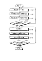
- FIG. 3 is a flowchart showing the dispensing operation of the sample dispensing method according to the first embodiment of the present invention.
- FIG. 4 is a diagram showing a state of a series of dispensing operations by the sample dispensing apparatus in the first embodiment.
- FIG. 5 is a simulation of the moisture concentration in the sample container when multiple items are dispensed with one sample in the first embodiment.
- FIG. 6 is a flowchart showing the dispensing operation of the sample dispensing method according to the second embodiment.
- FIG. 1 is a schematic configuration diagram showing an automatic analyzer according to the first embodiment of the present invention.
- FIG. 2 is a schematic configuration diagram showing a dispensing device used in the automatic analyzer of FIG.
- FIG. 3 is a flowchart showing the dispensing operation of the
- FIG. 7 is a diagram showing a state of a series of dispensing operations by the sample dispensing apparatus in the second embodiment.
- FIG. 8 is a simulation of the moisture concentration in the sample container when multi-item dispensing is performed in the second embodiment.
- FIG. 9 is a flowchart illustrating the dispensing operation of the sample dispensing method according to the third embodiment.
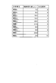
- FIG. 10 is a diagram showing the dispensing order of each analysis item based on the amount of sample suction in the third embodiment.
- FIG. 11 is a flowchart illustrating the dispensing operation of the sample dispensing apparatus according to the fourth embodiment.
- FIG. 12 is a diagram (with dummy ejection) showing a state of a series of dispensing operations by the sample dispensing apparatus in the fourth embodiment.
- FIG. 13 is a simulation of the water concentration in the specimen container when multi-item dispensing is performed in the fourth embodiment.
- FIG. 14 is a flowchart showing the dispensing operation of the sample dispensing method of the fifth embodiment.
- FIG. 15 is a simulation of the moisture concentration in the sample container when multi-item dispensing is performed in the fifth embodiment.
- FIG. 1 is a schematic configuration diagram showing an automatic analyzer that uses the sample dispensing method according to the first embodiment of the present invention.
- the automatic analyzer 1 controls a measurement mechanism 9 that measures light passing through a reaction product between a specimen and a reagent, and the entire automatic analyzer 1 including the measurement mechanism 9.
- the automatic analyzer 1 automatically performs analysis of a plurality of samples by cooperation of these two mechanisms.
- the measurement mechanism 9 roughly includes a sample table 2, a reaction table 3, a reagent table 4, a sample dispensing device 5, a reagent dispensing device 7, and dispensing probe cleaning devices 6 and 8.
- the sample table 2 includes a disk-shaped table, and includes a plurality of sample container storage portions 21 arranged at equal intervals along the circumferential direction of the table.
- a sample container 22 containing a sample is detachably stored in each sample container storage unit 21, a sample container 22 containing a sample is detachably stored in each sample container storage unit 21, a sample container 22 containing a sample is detachably stored in each sample container storage unit 21, a sample container 22 containing a sample is detachably stored.
- the sample container 22 has an opening 22a that opens upward.
- the sample table 2 is rotated in a direction indicated by an arrow in FIG. 1 by a sample table driving unit (not shown) with a vertical line passing through the center of the sample table 2 as a rotation axis.
- the sample container 22 is transported to the sample aspirating position where the sample is aspirated by the sample dispensing device 5.
- an identification label (not shown) having sample information relating to the type of sample contained and analysis items is attached to the sample container 22.
- the sample table 2 includes a reading unit 23 that reads information on the identification label of the sample container 22.
- the reaction table 3 has an annular table and includes a plurality of reaction container storage portions 31 arranged at equal intervals along the circumferential direction of the table.
- a transparent reaction container 32 for storing a sample and a reagent is detachably stored in an open shape upward.
- the reaction table 3 is rotated in a direction indicated by an arrow in FIG. 1 by a reaction table driving unit (not shown) with a vertical line passing through the center of the reaction table 3 as a rotation axis.
- the reaction container 32 is transported to the sample discharge position where the sample is discharged by the sample dispensing apparatus 5 or the reagent discharge position where the reagent is discharged by the reagent dispensing apparatus 7.
- the photometric device 33 has a light source 33a and a light receiving unit 33b.
- the light source 33a emits analysis light having a predetermined wavelength
- the light receiving unit 33b measures a light beam emitted from the light source 33a and transmitted through the reaction solution in which the sample and the reagent contained in the reaction container 32 have reacted.
- the light source 33 a and the light receiving unit 33 b are arranged at positions where the light source 33 a and the light receiving unit 33 b are opposed to each other in the radial direction with the reaction container storage unit 31 of the reaction table 3 interposed therebetween.
- the reaction table 3 includes a reaction container cleaning device 34 that discharges the measured reaction solution from the reaction container 32 and cleans the reaction container 32.
- the reagent table 4 has a disk-shaped table and includes a plurality of reagent container storage portions 41 arranged at equal intervals along the circumferential direction of the table.
- a reagent container 42 containing a reagent is detachably stored in each reagent container storage unit 41.
- the reagent container 42 has an opening 42a that opens upward.
- the reagent table 4 is rotated in a direction indicated by an arrow in FIG. 1 by a reagent table driving unit (not shown) with a vertical line passing through the center of the reagent table 4 as a rotation axis.
- the reagent container 42 is transported to the reagent suction position where the reagent is sucked by the reagent dispensing device 7.
- an identification label (not shown) having reagent information relating to the type and amount of reagent contained is affixed to the reagent container 42.
- the reagent table 4 includes a reading unit 43 that reads information on the identification label of the reagent container 42.
- the sample dispensing device 5 has a dispensing probe for aspirating and discharging a sample attached to the distal end, and freely moves up and down in the vertical direction and rotates around a vertical line passing through its proximal end as a central axis. Provide an arm.
- the sample dispensing device 5 is provided between the sample table 2 and the reaction table 3, sucks the sample in the sample container 22 transported to a predetermined position by the sample table 2 with a dispensing probe, rotates the arm, The sample is dispensed into the reaction container 32 conveyed to a predetermined position by the reaction table 3, and the sample is transferred into the reaction container 32 on the reaction table 3 at a predetermined timing.
- the reagent dispensing apparatus 7 has a dispensing probe 50 for aspirating and discharging the reagent attached to the distal end, and can freely move up and down in the vertical direction and rotate around a vertical line passing through its proximal end as a central axis.
- the reagent dispensing device 7 is provided between the reagent table 4 and the reaction table 3, sucks the reagent in the reagent container 42 transported to a predetermined position by the reagent table 4 with a dispensing probe, rotates the arm,
- the reagent is dispensed into the reaction container 32 transported to a predetermined position by the reaction table 3, and the reagent is transferred into the reaction container 32 on the reaction table 3 at a predetermined timing.
- FIG. 2 is a schematic configuration diagram of the sample dispensing device 5 (the same applies to the reagent dispensing device 7).
- the sample dispensing device 5 has a dispensing probe 50 as shown in FIG.
- the dispensing probe 50 is formed in a rod-like shape from stainless steel or the like, and the tip side is tapered.
- the upper proximal end is attached to the distal end of the arm 51 with the distal end directed downward.
- the arm 51 is horizontally arranged, and its base end is fixed to the upper end of the support shaft 52.
- the support shaft 52 is vertically arranged, and is rotated around the vertical axis O by the dispensing probe transfer unit 53.
- the arm 51 turns in the horizontal direction and moves the dispensing probe 50 in the horizontal direction. Further, the support shaft 52 is moved up and down along the vertical axis O by the dispensing probe transfer section 53.
- the support shaft 52 moves up and down
- the arm 51 moves up and down in the vertical direction
- the dispensing probe 50 moves up and down in the vertical (up and down) direction and in the longitudinal direction of the dispensing probe 50.
- the syringe 55 includes a cylindrical cylinder 55a to which the other end of the tube 54a is connected, and a plunger 55b provided so as to be able to advance and retreat in the cylinder 55a while sliding on the inner wall surface of the cylinder 55a.
- the plunger 55 b is connected to the plunger driving unit 56.
- the plunger drive unit 56 is configured using, for example, a linear motor, and moves the plunger 55b back and forth with respect to the cylinder 55a.
- One end of a tube 54b is connected to the cylinder 55a of the syringe 55.
- the other end of the tube 54b is connected to a tank 57 that contains the extrusion liquid L1. Further, an electromagnetic valve 58 and a pump 59 are connected in the middle of the tube 54b.
- an incompressible fluid such as distilled water or degassed water is applied as the extrusion liquid L1 as the extrusion liquid L1.
- the extrusion liquid L1 is also applied as a cleaning liquid for cleaning the inside of the dispensing probe 50.
- the sample dispensing device 5 drives the pump 59 and opens the electromagnetic valve 58 to fill the extruded liquid L1 accommodated in the tank 57 into the cylinder 55a of the syringe 55 via the tube 54b.
- the cylinder 55a is filled up to the tip of the dispensing probe 50 through the tube 54a.
- the electromagnetic valve 58 is closed and the pump 59 is stopped.
- the plunger drive unit 56 is driven to move the plunger 55b backward with respect to the cylinder 55a, thereby sucking the tip of the dispensing probe 50 through the extrusion liquid L1.
- the sample dispensing device 5 has a liquid level detection function (not shown) that detects the liquid level of the sample and reagent dispensed by the dispensing probe 50.
- a liquid level detection function for example, there is a function for detecting the liquid level based on a change in capacitance when the dispensing probe 50 comes into contact with a specimen or a sample.
- the dispensing probe cleaning device 6 is provided between the sample table 2 and the reaction table 3 and in the middle of the trajectory of the horizontal movement of the dispensing probe 50 in the sample dispensing device 5 to prevent carryover between samples. Therefore, every time the sample is dispensed by the dispensing probe 50, the dispensing probe 50 is washed by the dispensing probe washing device 6.
- the dispensing probe 50 is immersed in the washing water stored in the washing tank, or the outer wall surface is washed using an injection pressure such as a shower, and the inner wall surface is washed by ejecting the extrusion liquid L1 from the dispensing probe 50.
- the dispensing probe cleaning device 8 is provided between the reagent table 4 and the reaction table 3 and in the middle of the trajectory of the horizontal movement of the dispensing probe 50 in the reagent dispensing device 7 to prevent carryover between reagents. Therefore, every time the reagent is dispensed by the dispensing probe 50, the dispensing probe 50 is washed by the dispensing probe washing device 8.
- the sample dispensing device 5 dispenses a sample from the sample container 22 to the reaction container 32.
- the reagent dispensing device 7 dispenses a reagent from the reagent container 42 into the reaction container 32.
- the reaction container 32 into which the sample and the reagent are dispensed reacts while the sample and the reagent are agitated while being conveyed along the circumferential direction by the reaction table 3, and passes between the light source 33 a and the light receiving unit 33 b. pass.
- the analysis light emitted from the light source 33a and passed through the reaction solution in the reaction vessel 32 is measured by the light receiving unit 33b and analyzed for component concentration and the like.
- the reaction vessel 32 is used by the reaction vessel washing device 34 after the measurement reaction solution is discharged and washed, and then used again for analyzing the specimen.
- the control mechanism 10 includes a control unit 101, an input unit 102, an analysis unit 103, a storage unit 104, an output unit 105, a transmission / reception unit 107, and a dispensing order determination unit 108.
- Each unit included in the control mechanism 10 is electrically connected to the control unit 101.
- the control unit 101 is configured using a CPU or the like, and controls processing and operation of each unit of the automatic analyzer 1.
- the control unit 101 performs predetermined input / output control on information input / output to / from each of these components, and performs predetermined information processing on this information.
- the analysis unit 103 is connected to the photometric device 33 via the control unit 101, analyzes the component concentration of the sample based on the amount of light received by the light receiving unit 33 b, and outputs the analysis result to the control unit 101.
- the input unit 102 is a part that performs an operation of inputting an inspection item or the like to the control unit 101. For example, a keyboard or a mouse is used.
- the storage unit 104 is configured by using a hard disk that magnetically stores information and a memory that loads various programs related to the process from the hard disk and electrically stores them when the automatic analyzer 1 executes the process. Various information including the analysis result of the specimen is stored.
- the storage unit 104 may include an auxiliary storage device that can read information stored in a storage medium such as a CD-ROM, a DVD-ROM, or a PC card. Further, the storage unit 104 stores information required for analysis of all analysis items that can be analyzed, for example, analysis conditions such as a sample dispensing amount and a sample aspiration amount.
- the amount of sample dispensed means the amount of sample required for the actual analysis
- the amount of sample aspirated is the amount of sample aspirated in excess of the amount of sample required for analysis in consideration of the thinning of the sample in the extrusion liquid L1.
- excess suction amount is the amount of sample aspirated in excess of the amount of sample required for analysis in consideration of the thinning of the sample in the extrusion liquid L1.
- the sample aspiration volume is generally determined by the sample dispensing volume, so the dispensing order is determined by the sample dispensing volume.
- the sample dispensing amount and the sample suction amount are stored in the storage unit 104. Further, since the sample aspiration amount can be calculated as the sum of the sample dispensing amount and the excessive aspiration amount, it may be stored as an excessive aspiration amount instead of the sample aspiration amount.
- the output unit 105 is configured using a printer, a speaker, and the like, and outputs various information related to analysis under the control of the control unit 101.
- the output unit 105 includes a display unit 106 configured using a display or the like.
- the display unit 106 displays analysis contents, alarms, and the like, and a display panel or the like is used.
- the input unit 102 and the display unit 106 may be realized by a touch panel.
- the transmission / reception unit 107 has a function as an interface for performing transmission / reception of information according to a predetermined format via a communication network (not shown).
- the dispensing order determination unit 108 determines the dispensing order of each analysis item in one sample based on the sample dispensing amount or the sample aspiration amount required for each analysis item.
- control unit 101 is connected to each part of the above-described sample dispensing device 5 (same as the reagent dispensing device 7), a dispensing probe transfer unit 53, a plunger driving unit 56, an electromagnetic valve 58, and a pump 59. ing.
- the control mechanism 10 controls the operation process of the sample dispensing apparatus 5 using various programs related to each process of the automatic analyzer 1.
- the dispensing order determination unit 108 determines whether the sample is dispensed or dispensed based on the sample dispensing amount or the sample aspiration amount of each ordered analysis item.
- the dispensing order of each analysis item is determined, and the sample is dispensed according to the determined dispensing order.
- a predetermined amount of sample is dispensed from the sample container 22 held in the sample table 2 by the sample dispensing device 5 into the plurality of reaction containers 32 conveyed along the circumferential direction by the reaction table 3 based on the dispensing order.
- the reagent is dispensed from the reagent container 42 by the reagent dispensing device 7.
- the dispensing probe 50 after sample dispensing is washed by the dispensing probe cleaning device 6 every time dispensing is performed in order to prevent carryover between samples and clogging of the dispensing probe due to sample components and adhesion of dirt. .
- FIG. 3 is a flowchart showing the dispensing operation of the sample dispensing method in the first embodiment.
- the automatic analyzer 1 receives a test order for each sample (step S100).
- the examination order includes a specimen number and an analysis item, the examination order is accepted via the input unit 102, and the examination order is stored in the storage unit 104.
- the dispensing amount information of each analysis item is extracted (step S101).
- the automatic analyzer 1 Since the automatic analyzer 1 stores information required for analysis of all the analysis items that can be analyzed, for example, the sample dispensing amount, the reagent dispensing amount, the analysis conditions, and the like in the storage unit 104 for each analysis item.
- the dispensing amount information of each analysis item is extracted from the storage unit 104.
- the dispensing order determining unit 108 determines the order of dispensing each analysis item in one sample (step S102). In the first embodiment, dispensing is performed from a sample with a small amount.
- FIG. 4 is a diagram showing a state of a series of dispensing operations by the sample dispensing device 5.
- the dispensing probe 50 of the sample dispensing device 5 cleans the dispensing probe 50 with the dispensing probe washing device 6 after dispensing the sample into the reaction container 32 (see FIG. 4A).
- Cleaning is performed by cleaning the outer wall surface of the dispensing probe 50 by spraying the cleaning water L2 using a spraying pressure such as a shower, and the inner wall surface is cleaned by ejecting the extrusion liquid L1 from the dispensing probe 50. Distilled water, deaerated water, or the like is used as the washing water L2.
- the dispensing probe 50 in which minute water droplets W1 remain on the outer wall surface (FIG. (4-2)) is subsequently sucked from the sample container 22 (FIG. (4-3)), and the reaction container 32 performs analysis. A necessary sample amount is discharged (FIG. (4-4)).
- the dispensing probe 50 After washing with the dispensing probe cleaning device 6, minute water droplets W1 remain on the outer wall surface of the dispensing probe 50, and the dispensing probe 50 with the remaining water droplets W1 is inserted into the sample container 22 to suck the sample.
- the water droplet W1 adhering to the dispensing probe 50 is mixed in the sample S1.
- the sample S1 When the dispensing operation shown in FIG. 4 is continuously performed, the sample S1 is diluted by the moisture brought into the sample container 22, and the analysis accuracy is lowered.
- the amount of water brought in increases in proportion to the number of analysis items, so that the influence of the amount of water brought in increases.
- the order of analysis items in one sample is reduced by a simple technique such as changing the order of dispensing so that the amount of sample remaining in the sample container 22 is increased, thereby reducing the increase in water concentration due to moisture brought in. It is.
- FIG. 5 is a simulation of the moisture concentration in the sample container 22 when a sample is dispensed for a plurality of analysis items.
- the simulation conditions are that the initial sample amount in the sample container 22 is 130 ⁇ L, the number of times of dispensing is 10, and the sample dispensing amount at the time of dispensing varies from 1 to 20 ⁇ L. It is confirmed how much the moisture concentration of the sample S1 in the sample container 22 fluctuates in ascending order) and descending order (descending order). After washing, it is assumed that 0.2 ⁇ L of water droplets W1 remain on the outer wall of the dispensing probe 50, and the water droplets W1 that are brought in do not enter the sample S1 that is aspirated at that time (all remain in the container). It is said.
- the analysis item I for the first dispensing is dispensing 20 ⁇ L sample S1, so the sample volume after aspiration is 110 ⁇ L (130-20). It becomes. Since the initial sample does not contain water, the amount of water in the sample is 0 ⁇ L, and it is assumed that a 0.2 ⁇ L water droplet W1 is brought into the sample from the dispensing probe 50, and the total amount of water after dispensing is 0.2 ⁇ L. It becomes. The amount of liquid in the container is also brought into the sample amount after aspiration, and the amount of water is 110.2 ⁇ L.
- the total amount of water is divided by the amount of liquid in the container to obtain a water concentration of 0.18%.
- 20 ⁇ L sample is dispensed, but the sample amount for the analysis item J after aspirating the sample is aspirated by 20 ⁇ L from the liquid amount of 110.2 ⁇ L in the container after the end of the first dispensing. 2 ⁇ L, and the amount of water in the sample in the sample container 22 after the sample is aspirated is 0.16 ⁇ L (the previous water total amount 0.2 ⁇ the sample amount after dispensing 90.2 / the previous liquid amount in the container 110.2). .
- the order of dispensing of each analysis item in one sample is performed in order from the analysis item with the smaller sample dispensing amount (ascending order: A, B, C, D).
- the water concentration in the specimen container 22 after 10 dispensings is 2.04 (ascending order) and 2.94 (descending order), a difference of about 1.5 times.
- the first embodiment according to the present invention can not only reduce the influence due to the moisture brought in but also reduce the influence due to the carry-in of the previous specimen into the specimen container 22.
- the carry-in of the pre-sample to the post-sample is synergistically reduced by washing the dispensing probe 50, a certain amount of the pre-sample is brought in from the dispensing probe 50 each time the dispensing is performed. Therefore, the effect of carryover of the previous sample into the sample container 22 can be achieved by simply changing the dispensing order so that the order of dispensing of each analysis item in one sample is performed in order from the analysis item with the smaller sample dispensing amount. Can also be reduced.
- the control unit 101 After determination of the dispensing order by the dispensing order determination unit 108, the control unit 101 confirms whether or not there is a test order for the next sample. If there is no new test order (No in step S103), the control unit 101 proceeds to a dispensing operation. Then, the sample S1 is aspirated in the order of dispensing by the dispensing order determining unit 108 (step S104), and if there is a new examination order (step S103, Yes), the process returns to step S100 for accepting the examination order to 1 The dispensing order of each analysis item in the sample is determined. The aspirated sample S1 is discharged into the reaction container 32 (step S105).
- Step S106 the discharged sample S1 is reacted with a reagent, and photometric analysis is performed. Thereafter, the dispensing probe 50 is washed by the dispensing probe cleaning device 6 for dispensing the next analysis item (step S106), and until the dispensing of the accepted inspection order is completed (No at step S107). Steps S104 to S106 are repeated.
- air is not interposed between the extrusion liquid L1 and the specimen S1 (see FIGS. (4-3) and (4-4)), but the thinning of the specimen S1 by the extrusion liquid L1 is reduced. Therefore, it is possible to interpose air. In such a case, air may be sucked from the dispensing probe 50 before dispensing the sample from the sample container 22.
- the order of each analysis item in one sample is set to the order in which the sample dispensing amount is small.
- the order of each analysis item in one sample increases the polynomial approximation curve of the sample dispensing amount. Even in the order of dispensing in the decreasing direction, it is possible to effectively reduce the influence of the amount of water brought in.
- the first embodiment is a sample dispensing method in which the order of dispensing is determined based on the sample dispensing amount when only the sample amount required for analysis is dispensed by the sample dispensing apparatus
- the second embodiment is a second embodiment. Determines the order of dispensing based on the amount of sample aspirated by adding the amount of sample aspirated excessively in consideration of the thinning of the sample in the extruding liquid L1 to the amount of sample required for analysis.
- FIG. 6 is a flowchart showing the dispensing operation of the sample dispensing method of the second embodiment.
- the automatic analyzer 1 receives a test order for each sample (step S200).
- the examination order includes a specimen number and an analysis item, and the examination order is accepted via the input unit 102 and stored in the storage unit 104.
- sample aspiration amount information or sample dispensing amount information and surplus aspiration amount information for each analysis item is extracted (step S201).
- information required for analysis of all the analysis items that can be analyzed for example, sample dispensing amount, reagent dispensing amount, analysis conditions, etc. are stored in the storage unit 104 for each analysis item.
- the sample aspiration amount information or the sample dispensing amount information and the excess aspiration amount information of each analysis item are acquired from the storage unit 104.
- the dispensing order determination unit 108 determines the order of dispensing each analysis item in one sample (step S202). In the second embodiment, dispensing is performed from a sample with a small amount of sample suction.
- FIG. 7 is a diagram showing a state of a series of dispensing operations by the sample dispensing device 5. After dispensing the sample into the reaction container 32, the dispensing probe 50 of the sample dispensing device 5 discharges the excessively aspirated sample S1 and cleans the dispensing probe 50 with the dispensing probe cleaning device 6 (FIG. 7B). 1)).
- Cleaning is performed by cleaning the outer wall surface of the dispensing probe 50 using an injection pressure such as a shower, and the inner wall surface is cleaned by ejecting the extrusion liquid L1 from the dispensing probe 50.
- the dispensing probe 50 in which minute water droplets W1 remain on the outer wall surface (FIG. (7-2)) is subsequently sucked from the sample container 22 (FIG. (7-3)), and the reaction container 32 performs analysis.
- a necessary sample amount is discharged (FIG. 7D).
- minute water droplets W1 remain on the outer wall surface of the dispensing probe 50, and the dispensing probe 50 in which the water droplets W1 remain is inserted into the sample container 22 to suck the sample S1.
- the water droplet W1 adhering to the dispensing probe 50 is mixed in the sample S1.
- the sample S1 is diluted by the moisture brought into the sample container 22, and the analysis accuracy is lowered.
- the amount of water brought in increases in proportion to the number of analysis items, so the influence of the amount of water brought in increases.
- the order of analysis items in one sample is changed according to the amount of water brought in by a simple method such as changing the dispensing order so that the amount of sample remaining in the sample container 22 is increased as in the first embodiment. This is to reduce the increase in moisture concentration.
- FIG. 8 is a simulation of the water concentration in the sample container 22 when a multi-item dispensing is performed with one sample in the second embodiment.
- the simulation conditions are as follows: the initial sample volume in the sample container 22 is 200 ⁇ L, the number of times of dispensing is 10 times, the sample dispensing volume at the time of dispensing varies from 1 to 20 ⁇ L, and the surplus suction volume is uniformly 5 ⁇ L. Yes. After washing, it is assumed that 0.2 ⁇ L of water droplets W1 remain on the outer wall of the dispensing probe 50, and the water droplets W1 that are brought in do not enter the sample S1 that is aspirated at that time (all remain in the container). It is said.
- the first analysis item a in ascending order in which dispensing is started from a small dispensing volume is 6 ⁇ L of a total of 6 ⁇ L of a dispensing volume of 1 ⁇ L and an excess suction volume of 5 ⁇ L, and the sample S1 is 194 ⁇ L after aspiration.
- the dispensing order of each analysis item in one sample is performed in ascending order (ascending order: a, b, c, d%)
- ascending order ascending order
- water concentration in the specimen container 22 after 10 dispensings is 1.45 (ascending order) and 1.89 (descending order), a difference of about 1.3 times.
- the influence of moisture can be effectively reduced only by changing the dispensing order in accordance with the amount of sample suction.
- the influence due to the moisture brought in be reduced, but also the influence due to the carry-in of the previous specimen into the specimen container 22 can be similarly reduced.
- the carry-in of the pre-sample to the post-sample is synergistically reduced by washing the dispensing probe 50, a certain amount of the pre-sample is brought in from the dispensing probe 50 for each dispensing. Therefore, the influence of carry-over of the previous sample into the sample container 22 can be achieved only by changing the dispensing order so that the order of dispensing of each analysis item in one sample is performed in order from the analysis item with the smallest sample suction amount. It can be reduced.
- the control unit 101 After determining the dispensing order by the dispensing order determining unit 108, the control unit 101 confirms whether or not there is a test order for the next sample. If there is no new test order (No in step S203), the control unit 101 proceeds to a dispensing operation. Then, the sample S1 is aspirated in the order of dispensing by the dispensing order determining unit 108 (step S204), and if there is a new examination order (step S203, Yes), the process returns to step S200 for accepting the examination order and one sample is obtained. The dispensing order of each analysis item in is determined.
- the aspirated sample S1 is discharged into the reaction container 32 (step S205), and then a reagent is dispensed into the discharged sample S1, and a photometric analysis of a reaction product between the sample S1 and the reagent is performed.
- Dispensing probe 50 is washed after discharging an excessive amount of sample by dispensing probe washing device 6 for dispensing the next analysis item (step S206), until dispensing of the accepted inspection order is completed. (Step S207, No), Steps S204 to S206 are repeated.
- the sample S1 is excessively aspirated in consideration of the thinning of the sample S1 by the extrusion liquid L1, but in order to further reduce the thinning of the sample S1 by the extrusion liquid L1, the extrusion liquid L1 and the sample Air may be interposed between them. In such a case, air may be sucked from the dispensing probe 50 before dispensing the sample from the sample container 22.
- the sample aspiration amount of the analysis item to which surplus aspiration is not performed is set to 0 as the sample aspiration amount. What is necessary is just to calculate and determine dispensing order.
- the order of each analysis item in one sample is set to the order in which the sample aspiration amount is small, but the order of each analysis item in one sample is the increasing direction of the polynomial approximation curve of the sample aspiration amount. Even in the order of dispensing, carryover between samples can be effectively reduced.
- Embodiment 3 in which the order of dispensing of each analysis item in one sample is performed in the order determined in the dispensing order table stored in the storage unit 104 in advance will be described.
- an analysis order table for all the installed analysis items is created and held in advance, and when an examination order is received It is characterized in that the order of dispensing is determined in contrast to the analysis order table.
- FIG. 9 is a flowchart showing the dispensing operation of the sample dispensing method of the third embodiment.
- the automatic analyzer 1 receives a test order for each sample (step S300).
- the examination order is composed of a specimen number and an analysis item, and the examination order is received via the input unit 102 and stored in the storage unit 104.
- the storage unit 104 stores analysis information on all analysis items mounted on the automatic analyzer 1, and has sample aspiration information for each analysis item, or sample dispensing amount information and surplus aspiration information.
- a dispensing order table as shown in FIG. 10 is stored in the storage unit 104 in advance.
- the dispensing order determination unit 108 collates the analysis items of the inspection order received in step S300 with the dispensing order table, and determines the order of the ordered analysis items in the order of the dispensing order of the dispensing order table. (Step S301).
- a dispensing order table as shown in FIG. 10 in the storage unit 104 in advance, extraction of sample aspiration information or the like, sample dispensing amount and surplus aspiration amount, sample dispensing amount and surplus aspiration amount are stored. And the time of addition can be saved.
- the control unit 101 After determining the dispensing order by collating with the dispensing order table, the control unit 101 confirms whether or not there is an examination order for the next sample. If there is no new examination order (No in step S302), the dispensing operation is performed.
- the sample S1 is aspirated by the dispensing probe 50 (step S303). If there is a new inspection order (step S302, Yes), the flow returns to step S300 to accept the inspection order, and the dispensing order is determined.
- the aspirated sample S1 is discharged into the reaction container 32 (step S304), and then the discharged sample is reacted with a reagent to perform photometric analysis.
- the dispensing probe 50 is washed by the dispensing probe cleaning device 6 for dispensing the next analysis item (step S305), and until the dispensing of the accepted inspection order is completed (step S306, No), step Steps S303 to S305 are repeated.
- Embodiment 4 for determining the order of dispensing of each analysis item in one sample in the case of including analysis items to be subjected to dummy dispensing will be described.
- the accuracy of the sample discharge amount may decrease due to the movement of the arm 51 or the vibration of the drive unit in the apparatus.
- the dummy dispensing in addition to the sample dispensing amount and the surplus suction amount, the dummy discharge sample S1 is sucked, and the extra sucked dummy sample is discharged to the sample container 22 in advance, so that the influence of movement and vibration of the apparatus is exerted. Is performed to stabilize the dispensing amount.
- the sample discharge amount is set to an analysis item that is strictly required for analysis accuracy.
- the sample of the total amount of the sample dispensing amount, the excess suction amount, and the dummy discharge amount is used.
- the sample of the total amount of the sample dispensing amount and the excessive aspiration amount is aspirated.
- the sample S1 to be discharged by the dummy is discharged together with the moisture remaining on the inner wall of the dispensing probe 50, so that more moisture is mixed into the sample container 22.
- the analysis item to be subjected to the dummy dispensing is the period during which the moisture concentration is less likely to fluctuate due to moisture mixing, that is, the dispensing is performed while the amount of the sample in the sample container 22 is large.
- the dispensing order of each analysis item is dispensed from the order in which a larger amount of sample remains in the sample container 22, that is, from the smallest sample aspiration amount that is the total amount of the sample dispensing amount and the excess aspiration amount.
- FIG. 11 is a flowchart showing the dispensing operation of the sample dispensing apparatus of the fourth embodiment.
- the automatic analyzer 1 receives a test order for each sample (step S400).
- the examination order is composed of a specimen number and an analysis item, and the examination order is received via the input unit 102 and stored in the storage unit 104.
- sample aspiration amount information such as a sample dispensing amount, a surplus aspiration amount, and a dummy discharge amount for each analysis item is extracted (step S401).
- information required for analysis of all the analysis items that can be analyzed for example, sample dispensing amount, reagent dispensing amount, analysis conditions, etc. are stored in the storage unit 104 for each analysis item.
- the suction amount information and dummy discharge amount information of each analysis item are extracted from the storage unit 104.
- step S402 After extracting the sample suction amount information for each analysis item, it is confirmed whether there is an analysis item to be dispensed by dummy (step S402). If there is an analysis item to be dispensed by dummy (step S402, Yes), an analysis item to be subjected to dummy dispensing is selected from the analysis items (step S403), and the dispensing order of the analysis item group is determined (step S403). S404).
- the dispensing order is the order in which the amount of sample remaining in the sample container 22 increases, that is, the order in which the sample aspiration amount is the smallest of the sample dispensing amount and the excess aspiration amount (A).
- the sample to be dispensed by dummy is also aspirated in addition to the sample aspiration amount, but since the dummy dispensed amount is discharged into the sample container 22, it is not added to the reference amount when determining the dispensing order.
- dummy discharge is performed in the sample container 22 not only the water droplets W1 remaining on the outer wall of the dispensing probe 50 but also water droplets W1 discharged together with the dummy sample from the inner wall side are brought into the sample container 22.
- the amount of water brought in is the same, the final water concentration is lower and the difference in water concentration between the analysis items is smaller when more water is brought in while the amount of sample in the sample container 22 is large. Therefore, it is preferable to dispense the analysis item group to be subjected to dummy dispensing first, and then to dispense the analysis item group without dummy dispensing.
- FIG. 12 is a diagram showing a state of a series of dispensing operations by the sample dispensing device 5 (with dummy ejection).
- the dispensing probe 50 of the sample dispensing device 5 discharges the excessively aspirated sample S1 and cleans the dispensing probe 50 with the dispensing probe cleaning device 6 (FIG. (12-)). 1)). Cleaning is performed by cleaning the outer wall surface of the dispensing probe 50 using an injection pressure such as a shower, and the inner wall surface is cleaned by ejecting the extrusion liquid L1 from the dispensing probe 50.
- the dispensing probe 50 in which minute water droplets W1 remain on the outer wall surface (FIG.
- the specimen is diluted by the moisture brought into the specimen container 22 and the analysis accuracy is lowered.
- the amount of water brought in increases in proportion to the number of analysis items, so the influence of the amount of water brought in increases.
- the order of analysis items in one sample is divided so that the amount of sample remaining in the sample container 22 is large and the amount of water brought in is different when the amount of water brought in is different. By changing the order of the order, the effect of moisture brought in is reduced.
- FIG. 13 is a simulation of the water concentration in the sample container 22 when a multi-item dispensing is performed with one sample in the fourth embodiment.
- the simulation conditions are a total of 10 times: the initial sample amount in the sample container 22 is 200 ⁇ L, the number of dispensings is 5 times with dummy dispensing, and 5 times without dummy dispensing, and the sample dispensing amount at the time of dispensing is 1
- the amount of excess suction and the amount of dummy discharge are uniformly 5 ⁇ L.
- the first analysis item A ′ in the pattern 1 (ascending order) in which the analysis items that are not subjected to dummy discharge are dispensed first and the dispensing order starts with the smallest sample suction volume is the dispensing amount.
- a total of 6 ⁇ L of the sample S1 of 1 ⁇ L and an excess suction amount of 5 ⁇ L is aspirated, and 0.2 ⁇ L of the water droplet W1 brought in from the outer wall of the dispensing probe 50 is added to the sample S1 that has become 194 ⁇ L after the suction. 2 ⁇ L.
- the sixth analysis item F ′ of the pattern 1 (ascending order) in which dummy dispensing is performed is a sample that sucks and sucks a total of 11 ⁇ L of a dispensing volume of 1 ⁇ L, a surplus suction volume of 5 ⁇ L, and a dummy discharge volume of 5 ⁇ L. Of which 5 ⁇ L is discharged as a dummy.
- the amount of water in the sample in 130.8 ⁇ L is 0.77 ⁇ L (previous water total amount 0.81 ⁇ sample amount after dispensing 130.8 / previous container liquid amount 137), and the inner and outer walls of the dispensing probe 50 are added to this.
- the total amount of water is 1.17 ⁇ L, and the total amount of water in the container is 131.2 ⁇ L by adding 0.4 ⁇ L of water droplets W1, and the water concentration is 0. .89% (total water amount 1.17 / in-container liquid amount 131.2).
- simulation was performed by changing the conditions based on dummy dispensing (with and without) and sample aspiration volume, and as a result, the sample aspiration volume was small and the analysis items to be dispensed were dispensed first. As a result, it was confirmed that not only the final moisture concentration was kept low, but also the fluctuation of the moisture concentration between the analysis items became smaller.
- the dispensing order of the analysis item group that does not perform dummy dispensing is determined (step S405).
- the order in which the sample amount in the sample container 22 remains large that is, the sample aspiration amount that is the total amount of the sample dispensing amount and the excess aspiration amount is small.
- the order (B) is such that dispensing is performed.
- the order of dispensing of each analysis item in one sample is determined from (A) to (B ) (Step S406).
- the analysis item group for performing the dummy dispensing that brings in more water is dispensed first, and the dispensing is performed from the analysis item with the smaller sample suction amount in the sample container 22. This is because it is possible to suppress an increase in the moisture concentration of the specimen.
- step S406 After determining the order of dispensing of each analysis item in one sample (step S406), the control unit 101 confirms the presence or absence of a test order for the next sample (step S407), and if there is a new test order (step S407). , Yes), the process returns to step S400 to accept the test order, and the dispensing order of the analysis items of the next sample is determined. If there is no new test order (step S407, No), the process proceeds to a dispensing operation, and it is confirmed whether or not the sample to be dispensed performs dummy dispensing (step S408).
- step S408, No When dummy dispensing is not performed (step S408, No), the total amount of the sample S1 including the sample dispensing amount and the surplus suction amount is aspirated (step S414), and the sample is discharged into the reaction container 32 (step S411). .
- step S408, Yes When performing the dummy dispensing (step S408, Yes), the sample S1 of the total amount of the sample dispensing amount, the excess suction amount, and the dummy discharge amount is aspirated (step S409), and the dispensing probe 50 is lifted from the sample. Thereafter, dummy ejection is performed (step S410).
- Step S411 After the dummy discharge, the specimen is discharged into the reaction container 32 (step S411), and the dispensing probe 50 is cleaned by the dispensing probe cleaning device 6 (step S412). Until dispensing of the accepted inspection order is completed (No at Step S413), Steps S408 to S413 are repeated, and the sample S1 discharged to the reaction container 32 is reacted with the reagent, and photometric analysis is performed.
- the sample S1 is excessively aspirated in consideration of the thinning of the sample due to the extruding liquid L1, but in order to further reduce the thinning of the sample due to the extruding liquid L1, between the extruding liquid L1 and the sample.
- Air may be interposed. In such a case, air may be sucked from the dispensing probe 50 before dispensing the sample from the sample container 22.
- analysis items to be subjected to surplus aspiration and analysis items not to be performed are mixed. In such a case, the sample aspiration amount of the analysis item to which surplus aspiration is not performed is set to 0 as the sample aspiration amount. What is necessary is just to calculate and determine dispensing order.
- the order of dispensing analysis items of one sample is set such that the analysis item with the minimum amount of sample aspiration is the first, the maximum amount is the last, and the other orders are the reception order.
- the specimen water concentration can be reduced most in the specimen dispensing method according to the second or third embodiment in which the specimen is dispensed in ascending order, but the first part of the same specimen is dispensed.
- the sample water concentration can be greatly reduced by simply changing the last dispensing to the minimum and maximum amounts, compared to the case where the dispensing order is not changed at all.
- FIG. 14 is a flowchart showing the dispensing operation of the sample dispensing method of the fifth embodiment.
- the automatic analyzer 1 receives a test order for each sample (step S500).
- the examination order includes a specimen number and an analysis item, and the examination order is accepted via the input unit 102 and stored in the storage unit 104.
- sample aspiration amount information or sample dispensing amount information and surplus aspiration amount information of each analysis item is extracted (step S501).
- information required for analysis of all the analysis items that can be analyzed for example, sample dispensing amount, reagent dispensing amount, analysis conditions, etc. are stored in the storage unit 104 for each analysis item.
- the sample aspiration amount information or the sample dispensing amount information and the excess aspiration amount information of each analysis item are acquired from the storage unit 104.
- the dispensing order determination unit 108 determines the order of dispensing each analysis item in one sample (step S502).
- the analysis item with the smallest amount of sample aspiration is the first
- the analysis item with the largest amount is the last
- the other orders are the acceptance order.
- FIG. 15 is a simulation of the water concentration in the sample container 22 when a multisample is dispensed with one sample in the fifth embodiment. The simulation conditions are that the initial sample volume in the sample container 22 is 200 ⁇ L, the number of times of dispensing is 10 times, the sample dispensing volume at the time of dispensing varies from 1 to 25 ⁇ L, and the surplus suction volume is uniformly 5 ⁇ L. Yes.
- the order of accepting the analysis items of the sample is the pattern 2 shown in FIG. 15 (analysis items a ′, b ′, c ′, d ′, e ′, f ′, g ′, h ′, i ′, j ′).
- Dispensing the analysis item with the largest sample dispensing volume at the beginning of dispensing of the same sample, and finally dispensing the analysis item with the smallest sample dispensing volume, without changing the dispensing order Carryover can be greatly reduced.
- the dispensing order of each analysis item in one sample can be changed by changing the dispensing order so that the item with the smallest amount of sample suction is performed first and the item with the largest sample is performed last.
- the water concentration in the specimen container 22 after 10 dispensing is greatly different between 1.75 (pattern 1) and 2.10 (pattern 2). Even if the amount of water to be brought in is the same amount, the influence of moisture can be effectively reduced only by changing the dispensing order in accordance with the amount of sample suction.
- the fifth embodiment not only can the influence due to the moisture brought in be reduced, but also the influence due to the carry-in of the previous specimen into the specimen container 22 can be similarly reduced.
- the carry-in of the pre-sample to the post-sample is synergistically reduced by washing the dispensing probe 50, a certain amount of the pre-sample is brought in from the dispensing probe 50 for each dispensing. Therefore, the dispensing order of each analysis item in one sample can be changed by simply changing the dispensing order so that the item with the smallest amount of sample suction is performed first and the item with the largest sample is performed last. The influence of the carry-over of the specimen can also be reduced.
- the control unit 101 After determining the dispensing order by the dispensing order determining unit 108, the control unit 101 confirms whether or not there is a test order for the next sample. If there is no new test order (No in step S503), the control unit 101 proceeds to a dispensing operation. Then, the samples are aspirated in the order of dispensing by the dispensing order determining unit 108 (step S504). If there is a new examination order (step S503, Yes), the process returns to step S500 for accepting the examination order, and one sample is obtained. The dispensing order for each analysis item is determined.
- Step S505 The aspirated sample is discharged into the reaction container 32 (step S505), and then the reagent is dispensed into the discharged sample, and photometric analysis of the reaction product between the sample and the reagent is performed.
- Dispensing probe 50 is cleaned after discharging a sample with an excessive suction amount by dispensing probe cleaning device 6 for dispensing the next analysis item (step S506) until dispensing of the accepted inspection order is completed. (Step S507, No), Steps S504 to S506 are repeated.
- the specimen is aspirated excessively in consideration of the thinning of the specimen due to the extrusion liquid L1, but in order to further reduce the thinning of the specimen due to the extrusion liquid L1, air is interposed between the extrusion liquid L1 and the specimen. May be interposed. In such a case, air may be sucked from the dispensing probe 50 before dispensing the sample from the sample container 22.
- analysis items to be subjected to surplus aspiration and analysis items not to be performed are mixed. In such a case, the sample aspiration amount of the analysis item to which surplus aspiration is not performed is set to 0 as the sample aspiration amount. What is necessary is just to calculate and determine dispensing order.
- the dispensing order of the analysis items of one sample is assumed to be smaller than the sample suction amount of the analysis item to be dispensed last.
- the other orders are the order of acceptance.
- sample dispensing method and the analysis apparatus of the present invention are useful in an analysis apparatus that requires high analysis accuracy.
Landscapes
- Physics & Mathematics (AREA)
- Health & Medical Sciences (AREA)
- Life Sciences & Earth Sciences (AREA)
- Chemical & Material Sciences (AREA)
- Analytical Chemistry (AREA)
- Biochemistry (AREA)
- General Health & Medical Sciences (AREA)
- General Physics & Mathematics (AREA)
- Immunology (AREA)
- Pathology (AREA)
- Automatic Analysis And Handling Materials Therefor (AREA)
Abstract
検体分注装置(5)により検体容器(22)から反応容器(32)に検体を分注し、分注後に検体分注装置(5)を洗浄する自動分析装置(1)を用い、1検体につき多項目の分析を行う場合の検体分注方法であって、1検体における各分析項目の分注の順番を、最初に分注する分析項目の検体吸引量が最小であり、最後に分注する分析項目の検体吸引量が最大となるよう決定する分注順序決定ステップ(ステップS502)と、前記分注順序決定ステップにより決定した順番により1検体の各分析項目の分注を順次行なう分注ステップ(ステップS504およびステップS505)と、を含む。
Description
本発明は、1検体につき多項目の分析を行う分析装置の検体分注方法、および前記検体分注方法により検体を分注して分析を行う分析装置に関するものである。
従来、血液や尿などの検体を分析する自動分析装置では、先に分注した検体が分注プローブに付着したまま次に分注する検体に持ち越されることで、分析結果に影響を及ぼすキャリーオーバーを回避するため、分注プローブを洗浄する分注プローブ洗浄槽を備えている。この分注プローブ洗浄槽により洗浄された分注プローブの外壁には洗浄水が残存し、洗浄水が残存する状態で検体分注を行なうことにより、残存水が検体中に持ち込まれ、検体の希釈による濃度変化が発生する。この濃度変化を防止するためにプローブ先端を筒型状の真空吸引手段で真空吸引し、非接触で水滴を除去、乾燥する装置が開示されている(例えば、特許文献1参照)。
同様に、洗浄後の水滴の付着した分注プローブを、プローブの移動軌跡に保持させたワイパーに接触させ、水滴をふき取る装置が開示されている(例えば、特許文献2参照)。
しかしながら、特許文献1に記載の装置では、真空吸引手段である乾燥槽の設置コストやスペース的な問題を有するほか、分注プローブの乾燥を均一に行なうことは困難であるため、水持ち込み量がばらつき分析精度の低下を招くおそれがある。
また、特許文献2に記載の装置は、連続使用によりワイパーが損傷し、ランニングコストやメンテナンス等の問題を有するほか、特許文献1に開示される装置と同様に、分注プローブの乾燥を均一に行なうことは困難であるため、水持ち込み量がばらつき分析精度の低下を招くおそれがある。
本発明は、上記に鑑みてなされたものであって、1検体につき多項目の分析を行う場合において、洗浄後の分注プローブから持ち込まれる洗浄水の影響を極めて簡易に低減しうる検体分注方法、および前記検体分注方法により検体を分注して分析する分析装置を提供することを目的とする。
上述した課題を解決し、目的を達成するために、本発明にかかる検体分注方法は、検体分注手段により検体容器から反応容器に検体を分注し、分注後に該検体分注手段を洗浄する分析装置を用い、1検体につき多項目の分析を行う場合の検体分注方法であって、1検体における各分析項目の分注の順番を、最初に分注する分析項目の検体分注量が最後に分注する分析項目の検体分注量より小さいものとする分注順序決定ステップと、前記分注順序決定ステップにより決定した順番により1検体の各分析項目の分注を順次行なう分注ステップと、を含むことを特徴とする。
また、本発明にかかる検体分注方法は、検体分注手段により検体容器から反応容器に検体を分注し、分注後に該検体分注手段を洗浄する分析装置を用い、1検体につき多項目の分析を行う場合の検体分注方法であって、1検体における各分析項目の分注の順番を、最初に分注する分析項目の検体吸引量が最後に分注する分析項目の検体吸引量より小さいものとする分注順序決定ステップと、前記分注順序決定ステップにより決定した順番により1検体の各分析項目の分注を順次行なう分注ステップと、を含むことを特徴とする。
また、本発明にかかる検体分注方法は、上記発明において、前記分注順序決定ステップは、1検体における各分析項目の分注順に各分析項目の検体分注量または検体吸引量を並べた場合、前記検体分注量または前記検体吸引量の多項式近似曲線が増加方向となるような分注の順番とすることを特徴とする。
また、本発明にかかる検体分注方法は、上記発明において、前記分注順序決定ステップは、1検体における各分析項目の分注の順番が、最初に分注する分析項目の検体分注量または検体吸引量が最小であり、最後に分注する分析項目の検体分注量または検体吸引量が最大となるよう決定することを特徴とする。
また、本発明にかかる検体分注方法は、上記発明において、前記分注順序決定ステップは、1検体における各分析項目の分注の順番を、検体分注量または検体吸引量の小さい分析項目から順に行うよう決定することを特徴とする。
また、本発明にかかる検体分注方法は、上記発明において、前記検体吸引量は、検体分注量と余剰吸引量とを加算したものであり、該余剰吸引量の検体は前記検体分注手段の洗浄時に吐出されることを特徴とする。
また、本発明にかかる検体分注方法は、オーダーされた分析項目が前記ダミー吐出を必要とする場合、検体分注量と余剰吸引量とに加えダミー吐出用の検体を吸引する検体吸引ステップを含み、前記分注順序決定ステップは、ダミー吐出する分析項目群とダミー吐出なしの分析項目群とに分けてそれぞれ分注順を決定し、前記分注ステップは、ダミー吐出を行なう分析項目群から分注することを特徴とする。
また、本発明にかかる検体分注方法は、上記発明において、各分析項目に要する検体吸引量、または検体分注量と余剰吸引量とダミー吐出量とをそれぞれ取得する分注量抽出ステップを含むことを特徴とする。
また、本発明にかかる分析装置は、1検体につき多項目の分析を行う分析装置であって、1検体における各分析項目の分注の順番を、上記に記載の方法により決定する分注順序決定手段と、前記分注順序決定手段により決定した順番で検体の分注を行なう検体分注手段と、前記検体分注手段の洗浄を行なう洗浄手段と、前記検体分注手段により分注された検体の分析を行なう測定手段と、を備えたことを特徴とする。
また、本発明にかかる分析装置は、上記発明において、1検体における各分析項目の分注序列データを記憶する記憶手段を有し、前記分注順序決定手段は、前記記憶手段に記憶された分注序列データを参照して1検体における各分析項目の分注順序を決定することを特徴とする。
本発明は、1検体における各分析項目の分注の順番を、各分析項目に要する検体分注量または検体吸引量の小さいものから分注するといった簡易な方法により、検体中に持ち込まれる水分の影響を効果的に低減することができ、分析精度の向上を図ることが可能となる。
以下に添付図面を参照して、本発明にかかる検体分注方法および分析装置の好適な実施の形態を詳細に説明する。なお、この実施の形態により本発明が限定されるものではない。また、図面の記載において、同一部分には同一の符号を付している。
(実施の形態1)
図1は、本発明の実施の形態1にかかる検体分注方法を使用する自動分析装置を示す概略構成図である。図1に示すように、自動分析装置1は、検体と試薬との間の反応物を通過する光を測定する測定機構9と、測定機構9を含む自動分析装置1全体の制御を行なうとともに、測定機構9における測定結果の分析を行なう制御機構10とを備える。自動分析装置1は、これらの二つの機構が連携することによって複数の検体の分析を自動的に行なう。
図1は、本発明の実施の形態1にかかる検体分注方法を使用する自動分析装置を示す概略構成図である。図1に示すように、自動分析装置1は、検体と試薬との間の反応物を通過する光を測定する測定機構9と、測定機構9を含む自動分析装置1全体の制御を行なうとともに、測定機構9における測定結果の分析を行なう制御機構10とを備える。自動分析装置1は、これらの二つの機構が連携することによって複数の検体の分析を自動的に行なう。
まず、測定機構9について説明する。測定機構9は、大別して検体テーブル2と、反応テーブル3と、試薬テーブル4と、検体分注装置5と、試薬分注装置7と、分注プローブ洗浄装置6および8とを備えている。
検体テーブル2は、円盤状のテーブルを有し、該テーブルの周方向に沿って等間隔で複数配置された検体容器収納部21を備えている。各検体容器収納部21には、検体を収容した検体容器22が着脱自在に収納される。検体容器22は、上方に向けて開口する開口部22aを有している。また、検体テーブル2は、検体テーブル2の中心を通る鉛直線を回転軸として検体テーブル駆動部(図示せず)によって図1に矢印で示す方向に回転する。検体テーブル2が回転すると検体容器22は、検体分注装置5によって検体が吸引される検体吸引位置に搬送される。
なお、検体容器22には、収容された検体の種類や分析項目に関する検体情報を有する識別ラベル(図示せず)が貼り付けてある。一方、検体テーブル2は、検体容器22の識別ラベルの情報を読み取る読取部23を備えている。
反応テーブル3は、円環状のテーブルを有し、該テーブルの周方向に沿って等間隔で複数配置された反応容器収納部31を備えている。各反応容器収納部31には、検体と試薬を収容する透明な反応容器32が上方に向けて開口した形態で着脱自在に収納される。また、反応テーブル3は、反応テーブル3の中心を通る鉛直線を回転軸として反応テーブル駆動部(図示せず)によって図1に矢印で示す方向に回転する。反応テーブル3が回転すると反応容器32は、検体分注装置5によって検体が吐出される検体吐出位置や、試薬分注装置7によって試薬が吐出される試薬吐出位置に搬送される。
測光装置33は、光源33aおよび受光部33bを有している。光源33aは、所定波長の分析光を出射し、受光部33bは、光源33aから出射されて、反応容器32に収容された検体と試薬が反応した反応液を透過した光束を測定する。測光装置33は、前記光源33aと受光部33bが反応テーブル3の反応容器収納部31を挟んで半径方向に対向する位置に配置されている。なお、反応テーブル3は、測定後の反応液を反応容器32から排出し、該反応容器32を洗浄する反応容器洗浄装置34を備えている。
試薬テーブル4は、円盤状のテーブルを有し、該テーブルの周方向に沿って等間隔で複数配置された試薬容器収納部41を備えている。各試薬容器収納部41には、試薬を収容した試薬容器42が着脱自在に収納される。試薬容器42は、上方に向いて開口する開口部42aを有している。また、試薬テーブル4は、試薬テーブル4の中心を通る鉛直線を回転軸として試薬テーブル駆動部(図示せず)によって図1に矢印で示す方向に回転する。試薬テーブル4が回転すると試薬容器42は、試薬分注装置7によって試薬が吸引される試薬吸引位置に搬送される。
なお、試薬容器42には、収容された試薬の種類や収容量に関する試薬情報を有する識別ラベル(図示せず)が貼り付けてある。一方、試薬テーブル4は、試薬容器42の識別ラベルの情報を読み取る読取部43を備えている。
検体分注装置5は、検体の吸引および吐出を行なう分注プローブが先端部に取り付けられ、鉛直方向への昇降および自身の基端部を通過する鉛直線を中心軸とする回転を自在に行なうアームを備える。検体分注装置5は、検体テーブル2と反応テーブル3との間に設けられ、検体テーブル2によって所定位置に搬送された検体容器22内の検体を分注プローブによって吸引し、アームを旋回させ、反応テーブル3によって所定位置に搬送された反応容器32に分注して検体を所定タイミングで反応テーブル3上の反応容器32内に移送する。
試薬分注装置7は、試薬の吸引および吐出を行なう分注プローブ50が先端部に取り付けられ、鉛直方向への昇降および自身の基端部を通過する鉛直線を中心軸とする回転を自在に行なうアームを備える。試薬分注装置7は、試薬テーブル4と反応テーブル3との間に設けられ、試薬テーブル4によって所定位置に搬送された試薬容器42内の試薬を分注プローブによって吸引し、アームを旋回させ、反応テーブル3によって所定位置に搬送された反応容器32に分注して試薬を所定タイミングで反応テーブル3上の反応容器32内に移送する。
図2は、検体分注装置5(試薬分注装置7も同様である)の概略構成図である。検体分注装置5は、図2に示すように分注プローブ50を有している。分注プローブ50は、ステンレスなどによって棒管状に形成されたもので、先端側はテーパー形状をとる。先端を下方に向けて上方の基端がアーム51の先端に取り付けてある。アーム51は、水平配置され、その基端が支軸52の上端に固定してある。支軸52は、鉛直配置されており、分注プローブ移送部53によって鉛直軸Oを中心として回転する。支軸52が回転すると、アーム51が水平方向に旋回して、分注プローブ50を水平方向に移動させる。また、支軸52は、分注プローブ移送部53によって鉛直軸Oに沿って昇降する。支軸52が昇降すると、アーム51が鉛直方向に昇降して、分注プローブ50を鉛直(上下)方向であって分注プローブ50の長手方向に昇降させる。
分注プローブ50の基端には、チューブ54aの一端が接続される。このチューブ54aの他端は、シリンジ55に接続される。シリンジ55は、チューブ54aの他端が接続された筒状のシリンダー55aと、シリンダー55aの内壁面に摺動しながらシリンダー55a内を進退可能に設けられたプランジャー55bとを有する。プランジャー55bは、プランジャー駆動部56に接続される。プランジャー駆動部56は、例えばリニアモーターを用いて構成され、シリンダー55aに対するプランジャー55bの進退移動を行うものである。シリンジ55のシリンダー55aには、チューブ54bの一端が接続される。このチューブ54bの他端は、押し出し液L1を収容するタンク57に接続される。また、チューブ54bの途中には、電磁弁58およびポンプ59が接続される。なお、押し出し液L1としては、蒸留水や脱気水などの非圧縮性流体が適用される。この押し出し液L1は、分注プローブ50の内部の洗浄を行う洗浄液としても適用される。
検体分注装置5は、ポンプ59を駆動し、電磁弁58を開状態にすることでタンク57に収容されている押し出し液L1が、チューブ54bを経てシリンジ55のシリンダー55a内に充填され、さらにシリンダー55aからチューブ54aを経て分注プローブ50の先端まで満たされる。このように押し出し液L1が分注プローブ50の先端まで満たされた状態で、電磁弁58を閉状態にし、ポンプ59を止めておく。そして、検体や試薬の吸引を行う場合、プランジャー駆動部56を駆動してプランジャー55bをシリンダー55aに対して後退移動させることにより、押し出し液L1を介して分注プローブ50の先端部に吸引圧が印加され、この吸引圧によって検体や試薬が吸引される。一方、検体や試薬の吐出を行う場合には、プランジャー駆動部56を駆動してプランジャー55bをシリンダー55aに対して進出移動させることにより、押し出し液L1を介して分注プローブ50の先端部に吐出圧が印加され、この吐出圧によって検体や試薬が吐出される。
なお、検体分注装置5は、分注プローブ50で分注する検体および試薬の液面を検知する図示しない液面検知機能を備えている。液面検知機能には、例えば分注プローブ50が検体や試料に接した際の静電容量の変化によって液面を検知するものがある。
分注プローブ洗浄装置6は、検体テーブル2と反応テーブル3との間であって、検体分注装置5における分注プローブ50の水平移動の軌跡の途中位置に設けられ、検体間のキャリーオーバー防止のために、分注プローブ50により検体の分注を行なうたびに該分注プローブ洗浄装置6にて分注プローブ50の洗浄を行なう。洗浄槽に貯留した洗浄水に分注プローブ50を浸漬、またはシャワー等の噴射圧力を用いて外壁面を洗浄し、内壁面は、押し出し液L1を分注プローブ50から噴出させることにより洗浄する。分注プローブ洗浄装置8は、試薬テーブル4と反応テーブル3との間であって、試薬分注装置7における分注プローブ50の水平移動の軌跡の途中位置に設けられ、試薬間のキャリーオーバー防止のために、分注プローブ50により試薬の分注を行なうたびに該分注プローブ洗浄装置8にて分注プローブ50の洗浄を行なう。
このような構成の自動分析装置1では、反応容器32に対して検体分注装置5が、検体容器22から検体を分注する。また、反応容器32には、試薬分注装置7が試薬容器42から試薬を分注する。そして、検体および試薬が分注された反応容器32は、反応テーブル3によって周方向に沿って搬送される間に検体と試薬とが攪拌されて反応し、光源33aと受光部33bとの間を通過する。このとき、光源33aから出射され、反応容器32内の反応液を通過した分析光は、受光部33bによって測光されて成分濃度などが分析される。そして、分析が終了した反応容器32は、反応容器洗浄装置34によって測定後の反応液が排出されて洗浄された後、再度検体の分析に使用される。
つぎに、制御機構10について説明する。図1に示すように、制御機構10は、制御部101、入力部102、分析部103、記憶部104、出力部105、送受信部107および分注順序決定部108を備える。制御機構10が備える各部は、制御部101に電気的に接続されている。制御部101は、CPU等を用いて構成され、自動分析装置1の各部の処理および動作を制御する。制御部101は、これらの各構成部位に入出力される情報について所定の入出力制御を行い、かつ、この情報に対して所定の情報処理を行う。分析部103は、制御部101を介して測光装置33に接続され、受光部33bが受光した光量に基づいて検体の成分濃度等を分析し、分析結果を制御部101に出力する。入力部102は、制御部101へ検査項目等を入力する操作を行う部分であり、例えば、キーボードやマウス等が使用される。
記憶部104は、情報を磁気的に記憶するハードディスクと、自動分析装置1が処理を実行する際にその処理にかかわる各種プログラムをハードディスクからロードして電気的に記憶するメモリとを用いて構成され、検体の分析結果等を含む諸情報を記憶する。記憶部104は、CD-ROM、DVD-ROM、PCカード等の記憶媒体に記憶された情報を読み取ることができる補助記憶装置を備えてもよい。また、記憶部104は、分析可能なすべての分析項目についての分析に要する情報、たとえば、検体分注量、検体吸引量等の分析条件を記憶する。ここで、検体分注量は、実際の分析に要する検体量を意味し、検体吸引量は、分析に要する検体量に、押し出し液L1での検体の薄まりを考慮して余分に吸引した検体量(以下「余剰吸引量」と呼ぶ)を加えたものである。実際に吸引する量である検体吸引量に基づき分注順序を決定するのが好ましいが、一般的に検体分注量により検体吸引量は決定されるため、検体分注量により分注順序を決定することもできる。したがって、検体分注量と検体吸引量とが記憶部104に記憶される。また、検体吸引量は、検体分注量と余剰吸引量の和として算出できるため、検体吸引量ではなく余剰吸引量として記憶させてもよい。
出力部105は、プリンタ、スピーカー等を用いて構成され、制御部101の制御のもと、分析に関する諸情報を出力する。出力部105は、ディスプレイ等を用いて構成された表示部106を備える。表示部106は、分析内容や警報等を表示するもので、ディスプレイパネル等が使用される。入力部102および表示部106はタッチパネルによって実現するようにしてもよい。送受信部107は、図示しない通信ネットワークを介して所定の形式にしたがった情報の送受信を行なうインターフェースとしての機能を有する。分注順序決定部108は、各分析項目に要する検体分注量または検体吸引量に基づき1検体における各分析項目の分注の順序を決定する。
また、制御部101には、上述した検体分注装置5(試薬分注装置7も同様)の各部、分注プローブ移送部53、プランジャー駆動部56、電磁弁58、およびポンプ59が接続されている。制御機構10は、自動分析装置1の各処理にかかわる各種プログラムを用いて、検体分注装置5の動作処理の制御を行なう。
以上のように構成される自動分析装置1において、入力部102により検査オーダー受付後、オーダーされた各分析項目の検体分注量または検体吸引量に基づき、分注順序決定部108が1検体における各分析項目の分注順を決定し、決定した分注順により検体の分注は行なわれる。反応テーブル3によって周方向に沿って搬送されてくる複数の反応容器32に、検体分注装置5によって検体テーブル2に保持された検体容器22から、分注の順番に基づき所定量の検体が分注され、試薬分注装置7により試薬容器42から試薬が分注される。検体分注後の分注プローブ50は、検体間のキャリーオーバーや検体成分による分注プローブの詰まりや汚れ付着を防止すべく、分注が行なわれる度に分注プローブ洗浄装置6により洗浄される。
次に、本発明の実施の形態1にかかる検体分注方法について、図3~5を参照して詳細に説明する。図3は、実施の形態1における検体分注方法の分注動作を示すフローチャートである。まず、自動分析装置1は分析をスタートする際、各検体の検査オーダーを受付ける(ステップS100)。検査オーダーは検体番号と分析項目とを含み、入力部102を介して検査オーダーが受付けられ、記憶部104に検査オーダーが記憶される。次に各分析項目の分注量情報を抽出する(ステップS101)。自動分析装置1には分析可能なすべての分析項目についての分析に要する情報、たとえば、検体分注量、試薬分注量および分析条件等が分析項目毎に記憶部104に記憶されているので、記憶部104から各分析項目の分注量情報を抽出する。
分析項目毎に分注量情報を取得した後、分注順序決定部108により、1検体中における各分析項目の分注の順番を決定する(ステップS102)。実施の形態1では、検体分注量の小さいものから分注を行なう。図4は、検体分注装置5による一連の分注動作の状態を示す図である。検体分注装置5の分注プローブ50は、反応容器32への検体分注後、分注プローブ50を分注プローブ洗浄装置6で洗浄する(図(4-1)参照)。洗浄は、洗浄水L2をシャワー等の噴射圧力を用いて噴射することにより分注プローブ50の外壁面を洗浄し、内壁面は、押し出し液L1を分注プローブ50から噴出させることにより洗浄する。洗浄水L2には、蒸留水や脱気水などが使用される。外壁面に微小な水滴W1が残存する分注プローブ50は(図(4-2))、引き続いて検体容器22から検体S1を吸引し(図(4-3))、反応容器32に分析に必要な検体量が吐出される(図(4-4))。分注プローブ洗浄装置6での洗浄後、分注プローブ50外壁面には微小な水滴W1が残存し、水滴W1が残存する分注プローブ50を検体容器22内に挿入し検体を吸引するため、分注プローブ50に付着する水滴W1は検体S1中に混入する。図4に示す分注動作を連続的に行なうと、検体容器22内に持ち込まれる水分によって検体S1が希釈され分析精度が低下する。特に1検体について多項目の分析を行う場合には、持ち込まれる水分量も分析項目数に比例して増加するため、持ち込み水分量による影響が大きくなる。実施の形態1は、1検体における分析項目の順番を、検体容器22中に残存する検体量が多くなるように分注順を入れ替えるといった簡易な手法により、持ち込み水分による水分濃度上昇を低減させるものである。
図5は、1検体で複数の分析項目用の検体分注を行なった場合の検体容器22内の水分濃度のシミュレーションである。シミュレーションの条件は、検体容器22内の初期検体量が130μL、分注回数が10回であり、分注時の検体分注量は1~20μLまで変動するものとし、分注量の小さい順(昇順)と大きい順(降順)で、検体容器22内の検体S1の水分濃度がどれだけ変動するか確認したものである。洗浄後、分注プローブ50外壁には0.2μLの水滴W1が残留しているものとし、持ち込まれる水滴W1は、その回に吸引される検体S1には混入しない(すべて容器内に残留)ものとしている。たとえば、分注量が多いものから分注する降順のデータを用いて説明すると、分注1回目の分析項目Iは20μL検体S1を分注するため、吸引後検体量は110μL(130-20)となる。初期検体には水分は含まれていないものとして検体中水分量は0μLであり、これに分注プローブ50から0.2μLの水滴W1が持ち込まれたとして分注後の水合計量は0.2μLとなる。容器内液量も吸引後検体量に持ち込み水分量を加えて110.2μLとなり、水合計量を容器内液量で除して水分濃度0.18%を得る。分注2回目の分析項目Jでは20μL検体を分注するが、分析項目J用の検体吸引後の検体量は1回目の分注終了後の容器内液量110.2μLから20μL吸引して90.2μLとなり、検体吸引後の検体容器22内の検体中水分量は0.16μL(前回水合計量0.2×分注後検体量90.2/前回容器内液量110.2)となる。これに分注プローブ50から0.2μLの水滴W1が持ち込まれたとして水合計量は0.36μLとなり、容器内液量も0.2μLの水滴W1を加算して90.4μLとなり、水分濃度は0.40%(水合計量0.36/容器内液量90.4)となる。
このような条件下でのシミュレーションの結果、1検体における各分析項目の分注の順番を、検体分注量の小さい分析項目から順(昇順:A、B、C、D・・・)に行うように分注順序を変更しただけで、10回分注後の検体容器22内の水分濃度は2.04(昇順)と2.94(降順)と、約1.5倍もの相違が認められる。持ち込まれる水分量が同量であっても検体分注量に応じて分注順を変更するだけで効果的に水分による影響を低減できるものである。なお、本発明に係る実施の形態1は、持込水分による影響を低減できるだけでなく、検体容器22中への前検体の持ち込み(キャリーオーバー)による影響も同様に低減できるものである。前検体の後検体への持ち込みは、分注プローブ50の洗浄により相乗的に低減されるものの、分注の度に分注プローブ50から一定量の前検体の持ち込みが発生する。したがって、1検体における各分析項目の分注の順番を、検体分注量の小さい分析項目から順に行うように分注順序を変更するだけで、検体容器22中への前検体のキャリーオーバーによる影響も低減しうるものである。
分注順序決定部108による分注順の決定後、制御部101は、次検体の検査オーダーの有無を確認し、新たな検査オーダーがない場合は(ステップS103、No)、分注動作に移行して、分注順序決定部108による分注順に検体S1の吸引を行ない(ステップS104)、新たな検査オーダーがある場合は(ステップS103、Yes)、検査オーダーの受付のステップS100に戻って1検体における各分析項目の分注順序が決定される。吸引された検体S1は反応容器32に吐出され(ステップS105)、その後、吐出された検体S1を、試薬と反応させ、測光分析が行なわれる。その後、分注プローブ50は次の分析項目の分注のために、分注プローブ洗浄装置6で洗浄され(ステップS106)、受け付けられた検査オーダーの分注が終了するまで(ステップS107、No)、ステップS104~ステップS106が繰り返される。
上述した実施の形態1では、押し出し液L1と検体S1間にエアーが介在していないが(図(4-3)、(4-4)参照)、押し出し液L1による検体S1の薄まりを低減させるためにエアーを介在させることも可能である。かかる場合は、検体容器22から検体分注を行なう前に分注プローブ50からエアーを吸引させればよい。
なお、実施の形態1は、1検体における各分析項目の順番を検体分注量の小さい順番とするものであるが、1検体における各分析項目の順番が検体分注量の多項式近似曲線が増加減少方向とする分注順であっても、持込水分量による影響を効果的に低減できる。
(実施の形態2)
次に、1検体における各分析項目の分注の順番を検体吸引量に基づき決定する実施の形態2について説明する。実施の形態1は、分析に要する検体量のみを検体分注装置で分注する場合の検体分注量に基づき分注の順番を決定する検体分注方法であるのに対し、実施の形態2は、分析に要する検体量に、検体の押し出し液L1での薄まりを考慮して余分に吸引した検体量(余剰吸引量)を加えた検体吸引量に基づき分注の順番を決定する。
次に、1検体における各分析項目の分注の順番を検体吸引量に基づき決定する実施の形態2について説明する。実施の形態1は、分析に要する検体量のみを検体分注装置で分注する場合の検体分注量に基づき分注の順番を決定する検体分注方法であるのに対し、実施の形態2は、分析に要する検体量に、検体の押し出し液L1での薄まりを考慮して余分に吸引した検体量(余剰吸引量)を加えた検体吸引量に基づき分注の順番を決定する。
図6は、実施の形態2の検体分注方法の分注動作を示すフローチャートである。まず、自動分析装置1は分析をスタートする際、各検体の検査オーダーを受付ける(ステップS200)。検査オーダーは検体番号と分析項目からなり、入力部102を介して検査オーダーが受付けられ、記憶部104に記憶される。次に各分析項目の検体吸引量情報、または検体分注量情報および余剰吸引量情報を抽出する(ステップS201)。自動分析装置1には、分析可能なすべての分析項目についての分析に要する情報、たとえば、検体分注量、試薬分注量、分析条件等が分析項目毎に記憶部104に記憶されているので、記憶部104から各分析項目の検体吸引量情報、または検体分注量情報および余剰吸引量情報を取得する。
分析項目毎に検体吸引量を抽出した後、分注順序決定部108は、1検体中における各分析項目の分注の順番を決定する(ステップS202)。実施の形態2では、検体吸引量の小さいものから分注を行なう。図7は、検体分注装置5による一連の分注動作の状態を示す図である。検体分注装置5の分注プローブ50は、反応容器32への検体分注後、余剰吸引した検体S1を吐出するとともに分注プローブ50を分注プローブ洗浄装置6で洗浄する(図(7-1)参照)。洗浄は、シャワー等の噴射圧力を用いて分注プローブ50の外壁面を洗浄し、内壁面は、押し出し液L1を分注プローブ50から噴出させることにより洗浄する。外壁面に微小な水滴W1が残存する分注プローブ50は(図(7-2))、引き続いて検体容器22から検体S1を吸引し(図(7-3))、反応容器32に分析に必要な検体量が吐出される(図(7-4))。分注プローブ洗浄装置6での洗浄後、分注プローブ50外壁面には微小な水滴W1が残存し、水滴W1が残存する分注プローブ50を検体容器22内に挿入し検体S1を吸引するため、分注プローブ50に付着する水滴W1は検体S1中に混入する。図7に示す分注動作を連続的に行なうと、検体容器22内に持ち込まれる水分によって検体S1が希釈され分析精度が低下する。特に1検体について、多項目の分析を行う場合には、持ち込まれる水分量も分析項目数に比例して多くなるため、持ち込み水分量による影響も大きくなる。実施の形態2は、1検体における分析項目の順番を、実施の形態1と同様に検体容器22中に残存する検体量が多くなるように分注順を入れ替えるといった簡易な手法により、持ち込み水分による水分濃度上昇を低減させるものである。
図8は、実施の形態2において、1検体で多項目の分注を行なった場合の検体容器22内の水分濃度のシミュレーションである。シミュレーションの条件は、検体容器22内の初期検体量が200μL、分注回数が10回であり、分注時の検体分注量は1~20μLまで変動するものとし、余剰吸引量は一律5μLとしている。洗浄後、分注プローブ50外壁には0.2μLの水滴W1が残留しているものとし、持ち込まれる水滴W1は、その回に吸引される検体S1には混入しない(すべて容器内に残留)ものとしている。たとえば、分注量の少ないものから分注を行なう昇順の分注1回目の分析項目aは分注量1μLと余剰吸引量5μLの計6μLの検体を吸引し、吸引後194μLとなった検体S1に分注プローブ50から持ち込まれる0.2μLの水滴W1が加算され、容器内液量は194.2μLとなる。このような条件下でのシミュレーションの結果、1検体における各分析項目の分注の順番を、検体吸引量の小さい分析項目から順(昇順:a、b、c、d・・・)に行うように分注順序を変更しただけで、10回分注後の検体容器22内の水分濃度は1.45(昇順)と1.89(降順)と、約1.3倍もの相違が認められる。持ち込まれる水分量が同量であっても検体吸引量に応じて分注順を変更するだけで効果的に水分による影響を低減できるものである。なお、実施の形態2は、持込水分による影響を低減できるだけでなく、検体容器22中への前検体の持ち込み(キャリーオーバー)による影響も同様に低減できるものである。前検体の後検体への持ち込みは、分注プローブ50の洗浄により相乗的に低減されるものの、分注毎に分注プローブ50から一定量の前検体の持ち込みが発生する。したがって、1検体における各分析項目の分注の順番を、検体吸引量の小さい分析項目から順に行うように分注順序を変更するだけで、検体容器22中への前検体のキャリーオーバーによる影響も低減しうるものである。
分注順序決定部108による分注順の決定後、制御部101は、次検体の検査オーダーの有無を確認し、新たな検査オーダーがない場合は(ステップS203、No)、分注動作に移行して、分注順序決定部108による分注順に検体S1の吸引を行ない(ステップS204)、新たな検査オーダーがある場合は(ステップS203、Yes)、検査オーダーを受け付けるステップS200に戻って1検体における各分析項目の分注順序が決定される。吸引された検体S1は反応容器32に吐出され(ステップS205)、その後、吐出された検体S1中に試薬を分注し、検体S1と試薬との反応物の測光分析が行なわれる。分注プローブ50は次の分析項目の分注のために、分注プローブ洗浄装置6で余剰吸引量の検体を吐出後洗浄され(ステップS206)、受け付けられた検査オーダーの分注が終了するまで(ステップS207、No)、ステップS204~ステップS206が繰り返される。
上述した実施の形態2では、押し出し液L1による検体S1の薄まりを考慮して検体S1を余剰吸引しているが、押し出し液L1による検体S1の薄まりをさらに低減させるために、押し出し液L1と検体間にエアーを介在させてもよい。かかる場合は、検体容器22から検体分注を行なう前に分注プローブ50からエアーを吸引させればよい。また、余剰吸引を行なう分析項目と行なわない分析項目が混在する場合も考えられるが、かかる場合には、余剰吸引を行なわない分析項目の検体吸引量は、余剰吸引量を0として検体吸引量を算出して分注順序を決定すればよい。
なお、実施の形態2は、1検体における各分析項目の順番を検体吸引量の小さい順番とするものであるが、1検体における各分析項目の順番が検体吸引量の多項式近似曲線が増加方向とする分注順であっても、検体間のキャリーオーバーを効果的に低減できる。
(実施の形態3)
次に、1検体における各分析項目の分注の順番を、予め記憶部104に記憶させた分注序列表に定められた順番で行なう実施の形態3について説明する。実施の形態3の検体分注方法は、自動分析装置1が保持する検体分注量情報または検体吸引量情報に基づき、搭載全分析項目の分析序列表を予め作成、保持し、検査オーダー受付時に当該分析序列表と対照させて分注の順番を決定することを特徴とする。
次に、1検体における各分析項目の分注の順番を、予め記憶部104に記憶させた分注序列表に定められた順番で行なう実施の形態3について説明する。実施の形態3の検体分注方法は、自動分析装置1が保持する検体分注量情報または検体吸引量情報に基づき、搭載全分析項目の分析序列表を予め作成、保持し、検査オーダー受付時に当該分析序列表と対照させて分注の順番を決定することを特徴とする。
図9は、実施の形態3の検体分注方法の分注動作を示すフローチャートである。まず、自動分析装置1は分析をスタートする際、各検体の検査オーダーを受付ける(ステップS300)。検査オーダーは、検体番号と分析項目からなり、入力部102を介して検査オーダーが受付けられ、記憶部104に記憶される。記憶部104は、自動分析装置1の搭載全分析項目についての分析情報を記憶しており、分析項目毎の検体吸引量情報、または検体分注量情報および余剰吸引量情報を有している。実施の形態3では、分析項目毎の検体吸引量情報に加えて、図10に示すような分注序列表が予め記憶部104に記憶される。図10の分注序列表は、分析項目毎の検体分注量および余剰吸引量を合算した検体吸引量を予め算出し、当該検体吸引量に基づいて分注順序を決定したものであり、検体吸引量が多い順に分注順序が定められている。まず、分注順序決定部108は、ステップS300で受付けられた検査オーダーの分析項目と前記分注序列表を照合し、オーダーされた分析項目の順番を前記分注序列表の分注順序の順番に変更する(ステップS301)。予め図10に示すような分注序列表を記憶部104に記憶させておくことにより、検体吸引量情報等、または検体分注量および余剰吸引量の抽出や、検体分注量と余剰吸引量と加算の手間を省くことができる。
分注序列表と照合して分注順序を決定した後、制御部101は、次検体の検査オーダーの有無を確認し、新たな検査オーダーがない場合は(ステップS302、No)、分注動作に移行して分注プローブ50で検体S1の吸引を行ない(ステップS303)、新たな検査オーダーがある場合は(ステップS302、Yes)、検査オーダーを受け付けるステップS300に戻って分注順序が決定される。吸引された検体S1は反応容器32に吐出され(ステップS304)、その後、吐出された検体を試薬と反応させ、測光分析が行なわれる。分注プローブ50は次の分析項目の分注のために、分注プローブ洗浄装置6で洗浄され(ステップS305)、受け付けられた検査オーダーの分注が終了するまで(ステップS306、No)、ステップS303~ステップS305が繰り返される。
(実施の形態4)
次に、ダミー分注を行なう分析項目を含む場合において、1検体における各分析項目の分注の順番を決定する実施の形態4について説明する。検体分注において、アーム51の移動や装置内駆動部の振動に起因して検体吐出量の精度が低下する場合がある。ダミー分注は、検体分注量および余剰吸引量に加えダミー吐出用の検体S1を吸引し、余分に吸引したダミー検体を検体容器22に事前に吐出することにより、装置の移動や振動による影響を排除して分注量を安定化するために行なわれる。ダミー分注は、分析精度上、検体吐出量がシビアに要求される分析項目に設定され、ダミー分注が行なわれる場合は、検体分注量と余剰吸引量とダミー吐出量の合計量の検体を吸引し、ダミー分注が行なわれない場合は、検体分注量と余剰吸引量の合計量の検体を吸引する。ダミー分注を行なう場合、ダミー吐出される検体S1は分注プローブ50内壁に残存する水分とともに吐出されるため、検体容器22中により多くの水分が混入する。実施の形態4において、ダミー分注を行なう分析項目は、水分混入により水分濃度があまり変動しにくい期間、すなわち、検体容器22中の検体量が多いうちに分注を行い、かつ、1検体における各分析項目の分注の順番を検体容器22中の検体量がより多く残存するような順番、すなわち検体分注量と余剰吸引量との合計量である検体吸引量の小さい順から分注するものとする。
次に、ダミー分注を行なう分析項目を含む場合において、1検体における各分析項目の分注の順番を決定する実施の形態4について説明する。検体分注において、アーム51の移動や装置内駆動部の振動に起因して検体吐出量の精度が低下する場合がある。ダミー分注は、検体分注量および余剰吸引量に加えダミー吐出用の検体S1を吸引し、余分に吸引したダミー検体を検体容器22に事前に吐出することにより、装置の移動や振動による影響を排除して分注量を安定化するために行なわれる。ダミー分注は、分析精度上、検体吐出量がシビアに要求される分析項目に設定され、ダミー分注が行なわれる場合は、検体分注量と余剰吸引量とダミー吐出量の合計量の検体を吸引し、ダミー分注が行なわれない場合は、検体分注量と余剰吸引量の合計量の検体を吸引する。ダミー分注を行なう場合、ダミー吐出される検体S1は分注プローブ50内壁に残存する水分とともに吐出されるため、検体容器22中により多くの水分が混入する。実施の形態4において、ダミー分注を行なう分析項目は、水分混入により水分濃度があまり変動しにくい期間、すなわち、検体容器22中の検体量が多いうちに分注を行い、かつ、1検体における各分析項目の分注の順番を検体容器22中の検体量がより多く残存するような順番、すなわち検体分注量と余剰吸引量との合計量である検体吸引量の小さい順から分注するものとする。
図11は、実施の形態4の検体分注装置の分注動作を示すフローチャートである。まず、自動分析装置1は分析をスタートする際、各検体の検査オーダーを受付ける(ステップS400)。検査オーダーは、検体番号と分析項目からなり、入力部102を介して検査オーダーが受付けられ、記憶部104に記憶される。次に各分析項目の検体分注量、余剰吸引量およびダミー吐出量等の検体吸引量情報を抽出する(ステップS401)。自動分析装置1には、分析可能なすべての分析項目についての分析に要する情報、たとえば、検体分注量、試薬分注量、分析条件等が分析項目毎に記憶部104に記憶されているので、記憶部104から各分析項目の吸引量情報およびダミー吐出量情報を抽出する。
分析項目毎に検体吸引量情報を抽出した後、ダミー分注する分析項目があるか否か確認する(ステップS402)。ダミー分注する分析項目がある場合は(ステップS402、Yes)、分析項目の中からダミー分注を行なう分析項目を選択し(ステップS403)、該分析項目群の分注順序を決定する(ステップS404)。分注順序は、検体容器22中に残存する検体量が多くなるような順番、すなわち、検体分注量と余剰吸引量の合計量である検体吸引量の小さい順番とする(A)。ダミー分注する検体も検体吸引量に加えて吸引するが、ダミー分注量は検体容器22内に吐出されるので、分注順序の決定の際の基準量には加えない。また、検体容器22中にダミー吐出を行なうと、分注プローブ50外壁に残存する水滴W1だけでなく、内壁側からダミー検体とともに吐出される水滴W1も検体容器22中に持ち込まれる。水持込量が同一の場合、検体容器22内の検体量が多いうちに、より多くの水分が持ち込まれたほうが、最終的な水分濃度が低く、各分析項目間の水分濃度の差も小さくなることから、先にダミー分注を行なう分析項目群の分注を行い、その後にダミー分注なしの分析項目群の分注を行なうことが好ましい。
図12は、検体分注装置5による一連の分注動作の状態を示す図(ダミー吐出あり)である。検体分注装置5の分注プローブ50は、反応容器32への検体分注後、余剰吸引した検体S1を吐出するとともに分注プローブ50を分注プローブ洗浄装置6で洗浄する(図(12-1)参照)。洗浄は、シャワー等の噴射圧力を用いて分注プローブ50の外壁面を洗浄し、内壁面は、押し出し液L1を分注プローブ50から噴出させることにより洗浄する。外壁面に微小な水滴W1が残存する分注プローブ50は(図(12-2))、引き続いて検体容器22から検体を吸引し(図(12-3))、ダミー吐出を行なう場合はそのまま検体容器22中にダミー検体を吐出し(図(12-4))、その後反応容器32に分析に必要な検体量が吐出される(図(12-5))。分注プローブ洗浄装置6での洗浄後、分注プローブ50外壁面には微小な水滴W1が残存し、水滴W1が残存する分注プローブ50を検体容器22内に挿入し検体を吸引するため、分注プローブ50に付着する水滴W1は検体中に混入する。また、ダミー吐出時に、分注プローブ50内壁側からダミー検体と共に吐出される水滴W1が検体中に混入する。図12に示す分注動作を連続的に行なうと、検体容器22内に持ち込まれる水分によって検体が希釈され分析精度が低下する。特に1検体について、多項目の分析を行う場合には、持ち込まれる水分量も分析項目数に比例して多くなるため、持ち込み水分量による影響も大きくなる。実施の形態4は、1検体における分析項目の順番を、検体容器22中に残存する検体量が多く、かつ持ち込み水分量が異なる場合は持ち込まれる水分量が多いものから分注を行なうように分注順を入れ替えることにより、持ち込み水分による影響を低減させるものである。
図13は、実施の形態4において、1検体で多項目の分注を行なった場合の検体容器22内の水分濃度のシミュレーションである。シミュレーションの条件は、検体容器22内の初期検体量が200μL、分注回数がダミー分注あり5回、ダミー分注なし5回の計10回であり、分注時の検体分注量は1~20μLまで変動するものとし、余剰吸引量およびダミー吐出量は一律5μLとしている。洗浄後、分注プローブ50外壁には0.2μLの水滴W1が残留しているものとし、持ち込まれる水滴W1は、その回に吸引される検体S1には混入しない(すべて容器内に残留)ものとしている。また、ダミー分注がある場合は、分注プローブ50内壁側から0.2μLの水滴W1が混入し、検体容器22内にダミー吐出される検体5μLのうち、0.2μLが水滴W1と置き換わるものとする(4.8μLの検体と0.2μLの水滴W1がダミー吐出される)。
たとえば、ダミー吐出を行なわない分析項目を先に分注し、その分注順は検体吸引量の小さいものからとするパターン1(昇順)の分注1回目の分析項目A’は、分注量1μLと余剰吸引量5μLの計6μLの検体S1を吸引し、吸引後194μLとなった検体S1に分注プローブ50外壁から持ち込まれる0.2μLの水滴W1が加算され、容器内液量は194.2μLとなる。また、ダミー分注を行なうパターン1(昇順)の分注6回目の分析項目F’は、分注量1μLと余剰吸引量5μLとダミー吐出量5μLの計11μLの検体を吸引し、吸引した検体のうち5μLをダミー吐出する。ダミー吐出された5μLの内訳は、4.8μLの検体と0.2μLの水滴W1であり、吸引後(ダミー吐出後)検体量は、137(分注5回目終了後の容器内液量)-11+4.8=130.8μLとする。130.8μL中の検体中水分量は、0.77μL(前回水合計量0.81×分注後検体量130.8/前回容器内液量137)であり、これに分注プローブ50内外壁から0.2μLずつ計0.4μLの水滴W1が持ち込まれたとして水合計量は1.17μLとなり、容器内液量は0.4μLの水滴W1を加算して131.2μLとなり、水分濃度は0.89%(水合計量1.17/容器内液量131.2)となる。このような前提で、ダミー分注(有り無し)と検体吸引量に基づき条件を変更してシミュレーションを行なった結果、検体吸引量が少なく、かつダミー分注を行なう分析項目群から先に分注を行なうと、最終的な水分濃度が低く保たれるだけでなく、各分析項目間の水分濃度の変動もより小さくなることが確認された。
ダミー分注を行なう分析項目群の分注順序を決定した後(ステップS404)、ダミー分注を行わない分析項目群の分注順序を決定する(ステップS405)。ダミー分注を行わない分析項目群についても、検体容器22中の検体量が多く残存するような順番、即ち、検体分注量と余剰吸引量との合計量である検体吸引量が小さいものから分注を行なうような順番(B)とする。ダミー分注を行なう分析項目群の順番(A)とダミー分注を行なわない分析項目群の順番(B)決定の後、1検体における各分析項目の分注の順番を(A)→(B)の順番とする(ステップS406)。上記のシミュレーションに示すように、より多くの水分を持ち込むダミー分注を行なう分析項目群を先に分注し、かつ検体吸引量が小さい分析項目から分注を行なうほうが、検体容器22中に残存する検体の水分濃度の上昇を抑制できるためである。
1検体における各分析項目の分注の順番を決定した後(ステップS406)、制御部101は次検体の検査オーダーの有無を確認し(ステップS407)、新たな検査オーダーがある場合は(ステップS407、Yes)、検査オーダーを受け付けるステップS400に戻って次検体の分析項目の分注順序が決定される。新たな検査オーダーがない場合は(ステップS407、No)、分注動作に移行し、分注する検体がダミー分注を行なうか否か確認する(ステップS408)。ダミー分注を行なわない場合は(ステップS408、No)、検体分注量と余剰吸引量との合計量の検体S1を吸引し(ステップS414)、検体を反応容器32に吐出する(ステップS411)。ダミー分注を行なう場合は(ステップS408、Yes)、検体分注量と余剰吸引量とダミー吐出量との合計量の検体S1を吸引し(ステップS409)、分注プローブ50を検体から引き上げの後、ダミー吐出を行なう(ステップS410)。ダミー吐出の後、検体を反応容器32に吐出し(ステップS411)、分注プローブ洗浄装置6で分注プローブ50を洗浄する(ステップS412)。受け付けられた検査オーダーの分注が終了するまで(ステップS413、No)、ステップS408~ステップS413が繰り返され、反応容器32に吐出された検体S1は試薬と反応させ、測光分析が行なわれる。
上述した実施の形態4では、押し出し液L1による検体の薄まりを考慮して検体S1を余剰吸引しているが、押し出し液L1による検体の薄まりをさらに低減させるために、押し出し液L1と検体間にエアーを介在させてもよい。かかる場合は、検体容器22から検体分注を行なう前に分注プローブ50からエアーを吸引させればよい。また、余剰吸引を行なう分析項目と行なわない分析項目が混在する場合も考えられるが、かかる場合には、余剰吸引を行なわない分析項目の検体吸引量は、余剰吸引量を0として検体吸引量を算出して分注順序を決定すればよい。
(実施の形態5)
次に、1検体の分析項目の分注の順番を、検体吸引量が最小量の分析項目を最初に、最大量のものを最後とし、その他の順番は受付順とする実施の形態5について説明する。同じシーケンス内で最も検体水分濃度を低減しうるのは、検体吸引量が小さなものから順に分注していく実施の形態2または3の検体分注方法であるが、同一検体の分注の最初と最後の分注を最小量と最大量に変更するだけで、まったく分注の順序を変更しない場合より大幅に検体水分濃度を低減できる。
次に、1検体の分析項目の分注の順番を、検体吸引量が最小量の分析項目を最初に、最大量のものを最後とし、その他の順番は受付順とする実施の形態5について説明する。同じシーケンス内で最も検体水分濃度を低減しうるのは、検体吸引量が小さなものから順に分注していく実施の形態2または3の検体分注方法であるが、同一検体の分注の最初と最後の分注を最小量と最大量に変更するだけで、まったく分注の順序を変更しない場合より大幅に検体水分濃度を低減できる。
図14は、実施の形態5の検体分注方法の分注動作を示すフローチャートである。まず、自動分析装置1は分析をスタートする際、各検体の検査オーダーを受付ける(ステップS500)。検査オーダーは検体番号と分析項目からなり、入力部102を介して検査オーダーが受付けられ、記憶部104に記憶される。次に各分析項目の検体吸引量情報、または検体分注量情報および余剰吸引量情報を抽出する(ステップS501)。自動分析装置1には、分析可能なすべての分析項目についての分析に要する情報、たとえば、検体分注量、試薬分注量、分析条件等が分析項目毎に記憶部104に記憶されているので、記憶部104から各分析項目の検体吸引量情報、または検体分注量情報および余剰吸引量情報を取得する。
分析項目毎に検体吸引量を抽出した後、分注順序決定部108は、1検体中における各分析項目の分注の順番を決定する(ステップS502)。実施の形態5では、検体吸引量が最少量の分析項目を最初に、最大量のものを最後とし、その他の順番は受付順とする。図15は、実施の形態5において、1検体で多項目の分注を行なった場合の検体容器22内の水分濃度のシミュレーションである。シミュレーションの条件は、検体容器22内の初期検体量が200μL、分注回数が10回であり、分注時の検体分注量は1~25μLまで変動するものとし、余剰吸引量は一律5μLとしている。洗浄後、分注プローブ50外壁には0.2μLの水滴W1が残留しているものとし、持ち込まれる水滴W1は、その回に吸引される検体には混入しない(すべて容器内に残留)ものとしている。
たとえば、検体の分析項目の受付順が、図15に示すパターン2(分析項目a’、b’、c’、d’、e’、f’、g’、h’、i’、j’)とする。この検体の分析項目のうち、検体吸引量が最大となるのは、分析項目a’(検体吸引量30μL=25+5)であり、最小は分析項目j’(検体吸引量6μL=1+5)である。検体吸引量が最小量の分析項目j’を最初に、最大量の分析項目a’を最後に分注し、その他の分析項目は受付順となる。したがって、検体の分注順は、図15のパターン1(分析項目j’、b’、c’、d’、e’、f’、g’、h’、i’、a’)ようになる。同一検体の分注の最初に検体分注量が最大の分析項目の分注を行い、最後に検体分注量が最小の分析項目を分注するだけで、分注の順序を変更しない場合より大幅にキャリーオーバーの低減が可能となる。前記の条件下でのシミュレーションの結果、1検体における各分析項目の分注の順番を、検体吸引量が最小の項目を最初、最大の項目を最後に行うように分注順序を変更しただけで、10回分注後の検体容器22内の水分濃度は1.75(パターン1)と2.10(パターン2)と大きな相違が認められる。持ち込まれる水分量が同量であっても検体吸引量に応じて分注順を変更するだけで効果的に水分による影響を低減できるものである。なお、実施の形態5は、持込水分による影響を低減できるだけでなく、検体容器22中への前検体の持ち込み(キャリーオーバー)による影響も同様に低減できるものである。前検体の後検体への持ち込みは、分注プローブ50の洗浄により相乗的に低減されるものの、分注毎に分注プローブ50から一定量の前検体の持ち込みが発生する。したがって、1検体における各分析項目の分注の順番を、検体吸引量が最小の項目を最初、最大の項目を最後に行うように分注順序を変更するだけで、検体容器22中への前検体のキャリーオーバーによる影響も低減しうるものである。
分注順序決定部108による分注順の決定後、制御部101は、次検体の検査オーダーの有無を確認し、新たな検査オーダーがない場合は(ステップS503、No)、分注動作に移行して、分注順序決定部108による分注順に検体の吸引を行ない(ステップS504)、新たな検査オーダーがある場合は(ステップS503、Yes)、検査オーダーを受け付けるステップS500に戻って1検体における各分析項目の分注順序が決定される。吸引された検体は反応容器32に吐出され(ステップS505)、その後、吐出された検体中に試薬を分注し、検体と試薬との反応物の測光分析が行なわれる。分注プローブ50は次の分析項目の分注のために、分注プローブ洗浄装置6で余剰吸引量の検体を吐出後洗浄され(ステップS506)、受け付けられた検査オーダーの分注が終了するまで(ステップS507、No)、ステップS504~ステップS506が繰り返される。
上述した実施の形態5では、押し出し液L1による検体の薄まりを考慮して検体を余剰吸引しているが、押し出し液L1による検体の薄まりをさらに低減させるために、押し出し液L1と検体間にエアーを介在させてもよい。かかる場合は、検体容器22から検体分注を行なう前に分注プローブ50からエアーを吸引させればよい。また、余剰吸引を行なう分析項目と行なわない分析項目が混在する場合も考えられるが、かかる場合には、余剰吸引を行なわない分析項目の検体吸引量は、余剰吸引量を0として検体吸引量を算出して分注順序を決定すればよい。
また、実施の形態5の変形例として、1検体の分析項目の分注の順番を、最初に分注する分析項目の検体吸引量が最後に分注する分析項目の検体吸引量より小さいものとし、その他の順番は受付順とする例がある。たとえば、図15のパターン2の最初の分析項目a’(検体吸引量30μL=25+5)と最後の分析項目j’(検体吸引量6μL=1+5)の検体吸引量を対比して、検体吸引量が小さい分析項目j’を最初に分注することにより、まったく分注の順序を変更しない場合より大幅に検体水分濃度を低減できる。
る。
る。
以上のように、本発明の検体分注方法および分析装置は、高い分析精度が要求される分析装置において有用である。
1 自動分析装置
2 検体テーブル
4 試薬テーブル
5 検体分注装置
6、8 分注プローブ洗浄装置
7 試薬分注装置
9 測定機構
10 制御機構
21 検体容器収納部
22 検体容器
22a、42a 開口部
23、43 読取部
31 反応容器収納部
32 反応容器
33 測光装置
33a 光源
33b 受光部
34 反応容器洗浄装置
41 試薬容器収納部
42 試薬容器
50 分注プローブ
51 アーム
52 支軸
53 分注プローブ移送部
54a、54b チューブ
55 シリンジ
55a シリンダー
55b プランジャー
56 プランジャー駆動部
57 タンク
58 電磁弁
59 ポンプ
101 制御部
102 入力部
103 分析部
104 記憶部
105 出力部
106 表示部
107 送受信部
108 分注順序決定部
L1 押し出し液
L2 洗浄水
S1 検体
O 鉛直軸
2 検体テーブル
4 試薬テーブル
5 検体分注装置
6、8 分注プローブ洗浄装置
7 試薬分注装置
9 測定機構
10 制御機構
21 検体容器収納部
22 検体容器
22a、42a 開口部
23、43 読取部
31 反応容器収納部
32 反応容器
33 測光装置
33a 光源
33b 受光部
34 反応容器洗浄装置
41 試薬容器収納部
42 試薬容器
50 分注プローブ
51 アーム
52 支軸
53 分注プローブ移送部
54a、54b チューブ
55 シリンジ
55a シリンダー
55b プランジャー
56 プランジャー駆動部
57 タンク
58 電磁弁
59 ポンプ
101 制御部
102 入力部
103 分析部
104 記憶部
105 出力部
106 表示部
107 送受信部
108 分注順序決定部
L1 押し出し液
L2 洗浄水
S1 検体
O 鉛直軸
Claims (10)
- 検体分注手段により検体容器から反応容器に検体を分注し、分注後に該検体分注手段を洗浄する分析装置を用い、1検体につき多項目の分析を行う場合の検体分注方法であって、
1検体における各分析項目の分注の順番を、最初に分注する分析項目の検体分注量が最後に分注する分析項目の検体分注量より小さいものとする分注順序決定ステップと、
前記分注順序決定ステップにより決定した順番により1検体の各分析項目の分注を順次行なう分注ステップと、
を含むことを特徴とする検体分注方法。 - 検体分注手段により検体容器から反応容器に検体を分注し、分注後に該検体分注手段を洗浄する分析装置を用い、1検体につき多項目の分析を行う場合の検体分注方法であって、
1検体における各分析項目の分注の順番を、最初に分注する分析項目の検体吸引量が最後に分注する分析項目の検体吸引量より小さいものとする分注順序決定ステップと、
前記分注順序決定ステップにより決定した順番により1検体の各分析項目の分注を順次行なう分注ステップと、
を含むことを特徴とする検体分注方法。 - 前記分注順序決定ステップは、1検体における各分析項目の分注順に各分析項目の検体分注量または検体吸引量を並べた場合、前記検体分注量または前記検体吸引量の多項式近似曲線が増加方向となるような分注の順番とすることを特徴とする請求項1または2に記載の検体分注方法。
- 前記分注順序決定ステップは、1検体における各分析項目の分注の順番が、最初に分注する分析項目の検体分注量または検体吸引量が最小であり、最後に分注する分析項目の検体分注量または検体吸引量が最大となるよう決定することを特徴とする請求項1~3のいずれか一つに記載の検体分注方法。
- 前記分注順序決定ステップは、1検体における各分析項目の分注の順番を、検体分注量または検体吸引量の小さい分析項目から順に行うよう決定することを特徴とする請求項1~4のいずれか一つに記載の検体分注方法。
- 前記検体吸引量は、検体分注量と余剰吸引量とを加算したものであり、該余剰吸引量の検体は前記検体分注手段の洗浄時に吐出されることを特徴とする請求項1~5のいずれか一つに記載の検体分注方法。
- オーダーされた分析項目がダミー吐出を必要とする場合、検体分注量と余剰吸引量とに加えてダミー吐出用の検体を吸引する検体吸引ステップを含み、
前記分注順序決定ステップは、ダミー吐出する分析項目群とダミー吐出なしの分析項目群とに分けてそれぞれ分注順を決定し、
前記分注ステップは、ダミー吐出を行なう分析項目群から分注することを特徴とする請求項2~6のいずれか一つに記載の検体分注方法。 - 各分析項目に要する検体吸引量、または検体分注量と余剰吸引量とダミー吐出量とをそれぞれ取得する分注量抽出ステップを含むことを特徴とする請求項1~7のいずれか一つに記載の検体分注方法。
- 1検体につき多項目の分析を行う分析装置であって、
1検体における各分析項目の分注の順番を、請求項1~8のいずれか一つに記載の方法により決定する分注順序決定手段と、
前記分注順序決定手段により決定した順番で検体の分注を行なう検体分注手段と、
前記検体分注手段の洗浄を行なう洗浄手段と、
前記検体分注手段により分注された検体の分析を行なう測定手段と、
を備えたことを特徴とする分析装置。 - 1検体における各分析項目の分注序列データを記憶する記憶手段を有し、
前記分注順序決定手段は、前記記憶手段に記憶された分注序列データを参照して1検体における各分析項目の分注順序を決定することを特徴とする請求項9に記載の分析装置。
Applications Claiming Priority (2)
| Application Number | Priority Date | Filing Date | Title |
|---|---|---|---|
| JP2009-057017 | 2009-03-10 | ||
| JP2009057017A JP2010210434A (ja) | 2009-03-10 | 2009-03-10 | 検体分注方法および分析装置 |
Publications (1)
| Publication Number | Publication Date |
|---|---|
| WO2010104073A1 true WO2010104073A1 (ja) | 2010-09-16 |
Family
ID=42728362
Family Applications (1)
| Application Number | Title | Priority Date | Filing Date |
|---|---|---|---|
| PCT/JP2010/053884 Ceased WO2010104073A1 (ja) | 2009-03-10 | 2010-03-09 | 検体分注方法および分析装置 |
Country Status (2)
| Country | Link |
|---|---|
| JP (1) | JP2010210434A (ja) |
| WO (1) | WO2010104073A1 (ja) |
Citations (3)
| Publication number | Priority date | Publication date | Assignee | Title |
|---|---|---|---|---|
| JP2002162401A (ja) * | 2000-11-27 | 2002-06-07 | Hitachi Ltd | 自動分析装置 |
| JP2005249585A (ja) * | 2004-03-04 | 2005-09-15 | Olympus Corp | 自動分析装置及び分析方法 |
| JP2008209339A (ja) * | 2007-02-28 | 2008-09-11 | Hitachi High-Technologies Corp | 自動分析装置 |
-
2009
- 2009-03-10 JP JP2009057017A patent/JP2010210434A/ja not_active Withdrawn
-
2010
- 2010-03-09 WO PCT/JP2010/053884 patent/WO2010104073A1/ja not_active Ceased
Patent Citations (3)
| Publication number | Priority date | Publication date | Assignee | Title |
|---|---|---|---|---|
| JP2002162401A (ja) * | 2000-11-27 | 2002-06-07 | Hitachi Ltd | 自動分析装置 |
| JP2005249585A (ja) * | 2004-03-04 | 2005-09-15 | Olympus Corp | 自動分析装置及び分析方法 |
| JP2008209339A (ja) * | 2007-02-28 | 2008-09-11 | Hitachi High-Technologies Corp | 自動分析装置 |
Also Published As
| Publication number | Publication date |
|---|---|
| JP2010210434A (ja) | 2010-09-24 |
Similar Documents
| Publication | Publication Date | Title |
|---|---|---|
| JP7399330B2 (ja) | 自動分析装置、及びその洗浄方法 | |
| JP5300447B2 (ja) | 自動分析装置および自動分析装置における検体分注方法 | |
| JP5295069B2 (ja) | 分注装置、分析装置、および分注方法 | |
| EP2157435A1 (en) | Nozzle cleaning method, nozzle cleaning device, and automatic analyzer | |
| JP5744923B2 (ja) | 自動分析装置 | |
| JP5468219B2 (ja) | 自動分析装置、検体分注方法および検体分注装置の特別洗浄方法 | |
| CN108780102A (zh) | 自动分析装置 | |
| JP5231186B2 (ja) | 検体分注方法および分析装置 | |
| JP2010071766A (ja) | 分注装置、自動分析装置および分注不良確認方法 | |
| WO2021079645A1 (ja) | 自動分析装置および試薬の分注方法 | |
| CN116724238A (zh) | 自动分析装置以及自动分析装置中的检体的吸取方法 | |
| JP2010197047A (ja) | 分注方法、分析装置および分析装置 | |
| JP6711690B2 (ja) | 自動分析装置 | |
| EP3578994A1 (en) | Automatic analyzer | |
| WO2007132632A1 (ja) | 洗浄装置および自動分析装置 | |
| JP2010210434A (ja) | 検体分注方法および分析装置 | |
| JP6791690B2 (ja) | 自動分析装置 | |
| JP7613913B2 (ja) | 反応容器及び自動分析装置 | |
| JP6675162B2 (ja) | 自動分析装置 | |
| JP2012021892A (ja) | 自動分析装置及び分注方法 | |
| US11879902B2 (en) | Test method and dispensing device | |
| EP4700392A1 (en) | Automatic analysis device and automatic analysis method | |
| JP2011102744A (ja) | 分析装置における検体分注方法および分析装置 | |
| JP2011007568A (ja) | 自動分析装置 | |
| CN110501515B (zh) | 自动分析装置和自动分析方法 |
Legal Events
| Date | Code | Title | Description |
|---|---|---|---|
| 121 | Ep: the epo has been informed by wipo that ep was designated in this application |
Ref document number: 10750826 Country of ref document: EP Kind code of ref document: A1 |
|
| NENP | Non-entry into the national phase |
Ref country code: DE |
|
| 122 | Ep: pct application non-entry in european phase |
Ref document number: 10750826 Country of ref document: EP Kind code of ref document: A1 |