WO2010103577A1 - ハニカム建築構造体の基本ユニット及びその施工方法 - Google Patents
ハニカム建築構造体の基本ユニット及びその施工方法 Download PDFInfo
- Publication number
- WO2010103577A1 WO2010103577A1 PCT/JP2009/001694 JP2009001694W WO2010103577A1 WO 2010103577 A1 WO2010103577 A1 WO 2010103577A1 JP 2009001694 W JP2009001694 W JP 2009001694W WO 2010103577 A1 WO2010103577 A1 WO 2010103577A1
- Authority
- WO
- WIPO (PCT)
- Prior art keywords
- basic unit
- oblique column
- rigid region
- rigid
- oblique
- Prior art date
- Legal status (The legal status is an assumption and is not a legal conclusion. Google has not performed a legal analysis and makes no representation as to the accuracy of the status listed.)
- Ceased
Links
Images









Classifications
-
- E—FIXED CONSTRUCTIONS
- E04—BUILDING
- E04B—GENERAL BUILDING CONSTRUCTIONS; WALLS, e.g. PARTITIONS; ROOFS; FLOORS; CEILINGS; INSULATION OR OTHER PROTECTION OF BUILDINGS
- E04B1/00—Constructions in general; Structures which are not restricted either to walls, e.g. partitions, or floors or ceilings or roofs
- E04B1/34—Extraordinary structures, e.g. with suspended or cantilever parts supported by masts or tower-like structures enclosing elevators or stairs; Features relating to the elastic stability
- E04B1/3404—Extraordinary structures, e.g. with suspended or cantilever parts supported by masts or tower-like structures enclosing elevators or stairs; Features relating to the elastic stability supported by masts or tower-like structures
-
- E—FIXED CONSTRUCTIONS
- E04—BUILDING
- E04B—GENERAL BUILDING CONSTRUCTIONS; WALLS, e.g. PARTITIONS; ROOFS; FLOORS; CEILINGS; INSULATION OR OTHER PROTECTION OF BUILDINGS
- E04B1/00—Constructions in general; Structures which are not restricted either to walls, e.g. partitions, or floors or ceilings or roofs
- E04B1/18—Structures comprising elongated load-supporting parts, e.g. columns, girders, skeletons
- E04B1/24—Structures comprising elongated load-supporting parts, e.g. columns, girders, skeletons the supporting parts consisting of metal
-
- E—FIXED CONSTRUCTIONS
- E04—BUILDING
- E04B—GENERAL BUILDING CONSTRUCTIONS; WALLS, e.g. PARTITIONS; ROOFS; FLOORS; CEILINGS; INSULATION OR OTHER PROTECTION OF BUILDINGS
- E04B1/00—Constructions in general; Structures which are not restricted either to walls, e.g. partitions, or floors or ceilings or roofs
- E04B1/18—Structures comprising elongated load-supporting parts, e.g. columns, girders, skeletons
- E04B1/24—Structures comprising elongated load-supporting parts, e.g. columns, girders, skeletons the supporting parts consisting of metal
- E04B1/2403—Connection details of the elongated load-supporting parts
- E04B2001/2406—Connection nodes
-
- E—FIXED CONSTRUCTIONS
- E04—BUILDING
- E04B—GENERAL BUILDING CONSTRUCTIONS; WALLS, e.g. PARTITIONS; ROOFS; FLOORS; CEILINGS; INSULATION OR OTHER PROTECTION OF BUILDINGS
- E04B1/00—Constructions in general; Structures which are not restricted either to walls, e.g. partitions, or floors or ceilings or roofs
- E04B1/18—Structures comprising elongated load-supporting parts, e.g. columns, girders, skeletons
- E04B1/24—Structures comprising elongated load-supporting parts, e.g. columns, girders, skeletons the supporting parts consisting of metal
- E04B1/2403—Connection details of the elongated load-supporting parts
- E04B2001/2415—Brackets, gussets, joining plates
-
- E—FIXED CONSTRUCTIONS
- E04—BUILDING
- E04B—GENERAL BUILDING CONSTRUCTIONS; WALLS, e.g. PARTITIONS; ROOFS; FLOORS; CEILINGS; INSULATION OR OTHER PROTECTION OF BUILDINGS
- E04B1/00—Constructions in general; Structures which are not restricted either to walls, e.g. partitions, or floors or ceilings or roofs
- E04B1/18—Structures comprising elongated load-supporting parts, e.g. columns, girders, skeletons
- E04B1/24—Structures comprising elongated load-supporting parts, e.g. columns, girders, skeletons the supporting parts consisting of metal
- E04B1/2403—Connection details of the elongated load-supporting parts
- E04B2001/2421—Socket type connectors
-
- E—FIXED CONSTRUCTIONS
- E04—BUILDING
- E04B—GENERAL BUILDING CONSTRUCTIONS; WALLS, e.g. PARTITIONS; ROOFS; FLOORS; CEILINGS; INSULATION OR OTHER PROTECTION OF BUILDINGS
- E04B1/00—Constructions in general; Structures which are not restricted either to walls, e.g. partitions, or floors or ceilings or roofs
- E04B1/18—Structures comprising elongated load-supporting parts, e.g. columns, girders, skeletons
- E04B1/24—Structures comprising elongated load-supporting parts, e.g. columns, girders, skeletons the supporting parts consisting of metal
- E04B1/2403—Connection details of the elongated load-supporting parts
- E04B2001/2433—Connection details of the elongated load-supporting parts using a removable key
-
- E—FIXED CONSTRUCTIONS
- E04—BUILDING
- E04B—GENERAL BUILDING CONSTRUCTIONS; WALLS, e.g. PARTITIONS; ROOFS; FLOORS; CEILINGS; INSULATION OR OTHER PROTECTION OF BUILDINGS
- E04B1/00—Constructions in general; Structures which are not restricted either to walls, e.g. partitions, or floors or ceilings or roofs
- E04B1/18—Structures comprising elongated load-supporting parts, e.g. columns, girders, skeletons
- E04B1/24—Structures comprising elongated load-supporting parts, e.g. columns, girders, skeletons the supporting parts consisting of metal
- E04B1/2403—Connection details of the elongated load-supporting parts
- E04B2001/2448—Connections between open section profiles
-
- E—FIXED CONSTRUCTIONS
- E04—BUILDING
- E04B—GENERAL BUILDING CONSTRUCTIONS; WALLS, e.g. PARTITIONS; ROOFS; FLOORS; CEILINGS; INSULATION OR OTHER PROTECTION OF BUILDINGS
- E04B1/00—Constructions in general; Structures which are not restricted either to walls, e.g. partitions, or floors or ceilings or roofs
- E04B1/18—Structures comprising elongated load-supporting parts, e.g. columns, girders, skeletons
- E04B1/24—Structures comprising elongated load-supporting parts, e.g. columns, girders, skeletons the supporting parts consisting of metal
- E04B1/2403—Connection details of the elongated load-supporting parts
- E04B2001/2457—Beam to beam connections
Definitions
- the present invention relates to a basic unit for constructing a honeycomb building structure and a construction method using the basic unit.
- honeycomb structure a honeycomb building structure disclosed in Patent Documents 1 to 5 (hereinafter abbreviated as “honeycomb structure”).
- honeycomb structure in these documents is preferably applied to a tube frame.
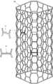
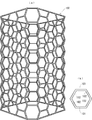
- FIG. 22 (a) shows an example of a honeycomb structure forming a tube frame (disclosed in Patent Document 1).
- This figure is a schematic view showing the overall shape of the honeycomb structure.
- An actual building structure is constructed by joining individual structural members to be pillars and beams, but in this drawing, the shape of each structural member and the joint location between the members are not specifically shown.
- FIG. 22B shows a hexagonal frame that is a unit structure of the honeycomb structure 100.
- One hexagonal frame has a pair of upper and lower horizontal sides 101 and two pairs of left and right oblique sides 102.
- adjacent hexagonal frames share one side member, thereby forming a honeycomb shape.
- the beam in the honeycomb structure 100 corresponds to the horizontal side 101 of the hexagonal frame and is not continuous in the horizontal direction.
- the pillars correspond to the left and right oblique sides 102 of the hexagonal frame, and are oblique pillars that are zigzag continuous in the vertical direction.
- Such a honeycomb structure has an advantage that a load applied to a building from various directions can be easily converted into an axial force of a beam or an oblique column.
- the rigidity peculiar to the honeycomb shape the structural stability and earthquake resistance of the entire building can be ensured only by the tube frame.
- the tube structure of the honeycomb structure has a smaller deformation and bending moment stress with respect to the same horizontal load than the tube structure of the general rigid frame structure. That is, when the strength against the same amount of deformation and bending moment stress is ensured, the honeycomb structure can be made thinner in beams and columns than the general rigid frame structure. In addition, since sufficient strength can be obtained even without a reinforcing structure inside the tube frame, a sufficient free internal space can be secured.
- a honeycomb structure can be constructed by joining a plurality of structural members, that is, basic units having substantially the same shape, according to the same regularity.
- a basic unit of the honeycomb structure shown in FIG. 22A for example, there is a trifurcated unit disclosed in Patent Document 3 (FIG. 1).
- the trifurcated unit has a shape having three leg portions extending radially from the center.
- the center of the trifurcated unit is arranged at the apex of the hexagonal frame, and the three legs are arranged to occupy the midpoints of the three sides extending from the apex.
- the connection between the three-pronged units is performed at the midpoint of each side of the hexagonal frame.
- honeycomb structure In order to construct a honeycomb structure, a large number of basic units having substantially the same shape and the same characteristics are required. Therefore, it is preferable that the honeycomb structure is produced in a factory under high quality control. Then, the factory-produced basic unit is carried into the site, and on the site, only the basic units are joined together.
- the present invention provides a basic unit for constructing a honeycomb structure, which has good workability on site and has sufficient proof stress at the apex of a hexagonal frame having a large stress load. Objective. Moreover, it aims at providing the construction method of the honeycomb structure using this basic unit.
- the configuration of the present invention that achieves the above object is as follows.
- the honeycomb structure constructed by the basic unit according to the present invention includes a plurality of hexagonal frames each having a pair of upper and lower horizontal sides and two pairs of left and right oblique sides, and two adjacent hexagonal frames sharing one side with each other. It has a structure formed from a hexagonal frame.
- the basic mode of the basic unit is a first rigid region portion and a second rigid region portion that are formed from a structural member and that respectively form end portions of one horizontal side of the hexagonal frame, and the first rigid region.
- a beam portion forming a portion between the region portion and the second rigid region portion, and extending obliquely upward and obliquely downward from the first rigid region portion to each midpoint of the two oblique sides of the hexagonal frame
- a first upper oblique column portion and a first lower oblique column portion forming the portion of the hexagonal frame, and each of the other two oblique sides of the hexagonal frame extending obliquely upward and obliquely downward from the second rigid region portion.
- the second lower oblique column part of another basic unit located in the position is connectable and one basic unit located in the lower side is connectable.
- the first inferior oblique pillar portion of a further base unit is positioned on the upper side can be bonded.
- the structural member is a structural steel material, and each of the first and second rigid regions is provided with a reinforcing steel material.
- the structural member is a structural steel material
- each of the first and second rigid regions is formed from a solid steel material
- the first and second The portion other than the rigid region is formed of a shape steel or a steel pipe.
- the structural member is a structural steel material
- the dimension of the basic unit in the prospective direction is the maximum dimension in the first and second rigid regions, and the beam portion A second dimension smaller than the maximum dimension at the middle point, and the maximum at the ends of the first and second upper oblique column parts and at the ends of the first and second lower oblique column parts.
- the third dimension is smaller than the dimension.
- the first and second rigid units may be provided when the dimensions of the basic unit in the prospective direction have the maximum dimension, the second dimension, and the third dimension.
- a first taper portion that gradually changes from the maximum dimension to the second dimension is provided between each of the region portions and the midpoint of the beam portion, and the first and second rigid portions are provided.
- second tapered portions that gradually change from the maximum dimension to the third dimension are provided.
- the construction method for constructing a honeycomb structure using the basic unit includes a step of stacking and joining a plurality of basic units in the vertical direction, and in the step, one basic unit located on the lower side
- the second upper oblique column of another basic unit located on the upper side and the second upper oblique line of one basic unit located on the lower side are joined to the first upper oblique column of
- the first lower oblique column of another basic unit located on the upper side is joined to the column.
- each end portion of the horizontal side of the hexagonal frame is formed by the first rigid region portion and the second rigid region portion beam portion.
- a portion between the two rigid regions is a beam portion.
- a first upper oblique column portion and a first lower oblique column portion extend obliquely upward and obliquely downward from the first rigid region portion, respectively.
- a second upper oblique column portion and a second lower oblique column portion extend obliquely upward and obliquely downward from the second rigid region portion, respectively.
- one basic unit is basically symmetrical.
- One basic unit can form a part of one horizontal side in the hexagonal frame of the honeycomb structure and a part to each midpoint of four oblique sides extending upward and downward from both ends thereof.
- the construction method according to the present invention is to build a honeycomb structure by stacking and joining a plurality of basic units in the vertical direction. Since the basic unit has a bilaterally symmetric shape, the crane can be lifted immediately after being brought into the site. Since it has a bilaterally symmetric shape, it is easy to maintain the correct orientation even in the air, particularly to maintain the beam portion horizontally. As a result, the joining operation in the air can be performed stably. Moreover, since the work in the construction method according to the present invention is only one kind of work for joining the ends of the oblique column parts of the two basic units positioned above and below, the work is simple. As described above, the construction method using the basic unit according to the present invention has an advantage that the workability is extremely good. As a result, a good and uniform bonded state can be realized.
- the basic unit according to the present invention is suitable for factory production, and the basic unit having the same characteristics can be mass-produced by advanced quality control. Only the ends of the four oblique column portions in the basic unit are joined at the site. These joints correspond to the midpoint of the hypotenuse of the hexagonal frame in the honeycomb structure. The midpoint of the hypotenuse of the hexagonal frame is a portion where the bending moment stress is the smallest in the honeycomb structure. Therefore, relatively strong strength is not required for bonding at this point, and pin bonding is sufficient. Since the work for pin joining is simpler than the work for rigid joining, there is less burden on the site. Moreover, advanced quality control is unnecessary for the joining state.
- the basic unit according to the present invention is an integral structural member as a whole.
- the first and second rigid zone portions are base portions that branch in three directions, that is, a beam portion and two oblique column portions, respectively.
- Each rigid region portion is inherently rigidly connected and forms a rigid region.
- “essentially” means “when the basic unit is completed”.
- the position of the two rigid regions is the apex position of the hexagonal frame of the honeycomb structure. This apex position is a portion where the stress of the bending moment is greatest in the honeycomb structure. Therefore, in the basic unit of the present invention, the place where the most proof stress is required is essentially a rigid region.
- the midpoint of the horizontal side of the hexagonal frame has a smaller bending moment stress than the apex, but is larger than the midpoint of the hypotenuse. Since the basic unit is an integral structural member, there is essentially no joint at the midpoint of the beam, and rigidity is ensured.
- the basic unit of the present invention has an optimum shape in terms of structural strength as a unit for constructing a honeycomb structure.
- this rigid region can be further strengthened by providing a reinforcing steel material in each of the two rigid regions. Or the same effect is acquired also by making two rigid zone parts into a solid steel material, respectively. As a result, it is possible to realize the proof stress required for the maximum location of the bending moment stress in the honeycomb structure.
- the dimension in the prospective direction is set to the maximum dimension in the two rigid regions, and the dimension is smaller than the maximum dimension at the midpoint of the beam part, the end of the upper inclined column part, and the end of the lower inclined column part. Furthermore, it is also preferable to provide a tapered portion with a gradual change between the maximum dimension portion and the smaller dimension portion.
- the optimum proof stress can be designed according to the magnitude of the bending moment stress at each location.
- the method of increasing the proof strength by increasing the amount of material at a location where a large stress is applied, and reducing the amount of material at a location where the stress is relatively small efficiently uses the material, It also has the effect of saving resources and reducing costs.
- FIG. It is an example of the honeycomb structure which forms the tube frame constructed
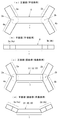
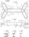
- (A) is a front view of one embodiment of the basic unit, (b) is a plan view thereof, (c) is a front view of another embodiment of the basic unit, and (d) is a plan view thereof.
- FIG. It is a schematic diagram which shows the relationship between the hexagonal frame which comprises a honeycomb structure, and a basic unit. It is a schematic diagram which shows the relationship of the stress of the bending moment with respect to the horizontal load in a honeycomb structure, and a basic unit.
- FIG. 1 shows an embodiment (the same shape as FIG. 22) of a honeycomb structure forming a tube frame constructed using the basic unit of the present invention.
- the honeycomb structure 100 is a main frame and is the most important skeleton that bears a long-term load (fixed load + load load) of the entire building.
- the honeycomb structure 100 has a horizontal cross-sectional shape that is substantially rectangular, and has four flat side surfaces that are erected.
- the used basic units U and U1 are respectively taken out and illustrated.
- the basic unit U is a basic unit for forming flat side portions
- the basic unit U1 is a basic unit for forming bent portions at four corners.
- FIG. 2 shows another embodiment of a honeycomb structure forming a tube frame constructed using the basic unit of the present invention.
- the honeycomb structure 101 has a substantially circular horizontal cross section, and has a substantially cylindrical side surface portion and a dome-shaped zenith portion which are erected.
- the used basic units U2 and U3 are respectively taken out and illustrated.
- the basic unit U2 is a basic unit for forming a cylindrical side surface portion
- the basic unit U3 is a basic unit for forming a dome surface.
- Another deformation unit is used at the zenith.
- FIG. 3 shows a basic form of the basic unit according to the present invention.
- A is the front view of one Example of the basic unit U used in order to form the flat part of a honeycomb structure
- (b) is the top view.
- C is a front view of one embodiment of the basic units U1, U2, U3 used for forming a bent portion or a curved portion of the honeycomb structure
- (d) is a plan view thereof.
- the basic unit U for a flat portion shown in the front view of FIG. 3A includes a first rigid region portion 2a and a second rigid region portion 2b, and a beam portion 1 is formed between these two rigid region portions. Yes. Further, a first upper oblique column portion 3a extends obliquely upward from the first rigid region portion 2a, and a first lower oblique column portion 4a extends obliquely below. A second upper oblique column portion 3b extends obliquely upward from the second rigid region portion 2b, and a second lower oblique column portion 4b extends obliquely below.
- the basic unit U has a symmetrical shape in front view.
- the first rigid region portion 2a is a base portion that branches in three directions: the beam portion 1, the first upper oblique column portion 3a, and the first lower oblique column portion 4a.
- the second rigid region portion 2b is a base portion that branches in three directions of the beam portion 1, the second upper oblique column portion 3b, and the second lower oblique column portion 4b.
- the beam portion 1, the upper oblique column portions 3a and 3b, and the lower oblique column portions 4a and 4b extend linearly.
- the basic unit U1, U2, U3 for the bent portion or the curved portion shown in the front view of FIG. 3C includes two rigid zone portions 2a, 2b, a beam portion 1, and four oblique column portions 3a, 4a. 3b and 4b are the same as the basic unit U.
- the basic unit U, U2, U3 for the bending portion or the bending portion is composed of the upper oblique column portions 3a, 3b and the lower oblique column portion 4a, Each 4b extends at a predetermined angle.
- the left and right oblique column portions are bent in the same direction with respect to the beam portion, but as another example, the left and right oblique column portions may be bent in different directions with respect to the beam portion.
- honeycomb frames having various shapes.
- the basic unit according to the present invention is an integral structural member as a whole.
- “Integral” in this case includes, for example, a case where a plurality of steel parts are integrated by welding.
- FIG. 4A is a front view schematically showing the relationship between the hexagonal frame H that is a unit structure of the honeycomb structure 100 and the basic unit U.
- Each of the hexagonal frames H includes six side members including a pair of opposed horizontal sides h1 and h4, a pair of opposed left and right oblique sides h2 and h5, and another pair of opposed left and right oblique sides h3 and h6. Further, two adjacent hexagonal frames H share one side member.
- the plurality of hexagonal frames H form a honeycomb shape.
- the hexagonal frame H is basically a hexagon that is vertically symmetric and symmetric in the front view.
- a cylindrical portion that gradually narrows upward or a dome portion may have a form that is not vertically symmetric or a deformed form that is neither vertically symmetric nor symmetric. Even if it is such a deformation
- the first rigid region portion 2a and the second rigid region portion 2b of the basic unit U form respective end portions of one horizontal side in the hexagonal frame H, that is, the apexes C1 and C2.
- the beam portion 1 forms a portion of one horizontal side h1, that is, a portion between the first rigid region portion 2a and the second rigid region portion 2b.
- the first upper oblique column portion 3a forms a portion from the first rigid region portion 2a to the midpoint M2 of the oblique side h2 extending obliquely upward.
- the first lower oblique column portion 4a forms a portion from the first rigid region portion 2a to the midpoint M3 of the oblique side h3 extending obliquely downward.
- the second upper oblique column portion 3b forms a portion from the second rigid region portion 2b to the midpoint M4 of the oblique side h6 extending obliquely upward.
- the second lower oblique column portion 4b forms a portion from the second rigid region portion 2b to the midpoint M5 of the oblique side h5 extending obliquely downward.
- FIG. 4B is a diagram schematically illustrating the relationship between the stress of the bending moment with respect to the horizontal load in the honeycomb structure 100 and the basic unit U.
- the horizontal axis of the graph in the figure represents the distance along the axial direction of the right half of the basic unit U, and the vertical axis represents the relative change in the magnitude of the bending moment stress. Since the basic unit U is symmetrical, the left half is the same as the right half.
- the bending moment stress in the honeycomb structure 100 becomes maximum at the vertex C2 of the hexagonal frame.
- the bending moment stress decreases from the vertex C2 of the hexagonal frame toward the midpoint M1 of the horizontal side.
- the stress on one horizontal side is minimal at the midpoint M1.
- the bending moment stress decreases from the vertex C2 of the hexagonal frame toward the midpoint M4 of the hypotenuse.
- the stress on one hypotenuse is minimal at the midpoint M4.
- the bending moment stress at the midpoint M4 of the hypotenuse is smaller than that at the midpoint M1 of the horizontal side. Therefore, the bending moment stress in the honeycomb structure 100 is minimized at the midpoint M4 of the hypotenuse.
- the stress applied to the two rigid regions 2a, 2b is the maximum, and the stress applied to the ends of the four oblique column portions 3a, 3b, 4a, 4b is the minimum. Become. Therefore, the basic unit U is required to have the most proof stress in the two rigid regions. Since the basic unit U is an integral structural member, the two rigid region portions 2a and 2b are inherently rigid joints, and inherently rigid regions are formed. Here, “essentially” means “when the basic unit U is completed”. Therefore, the rigid regions 2a and 2b have high proof stress.
- the basic unit of the present invention inherently has a shape that is optimally adapted to the stress distribution of the honeycomb structure.
- FIG. 5 is a diagram for explaining a construction method for constructing a honeycomb structure using the basic unit of the present invention.
- the honeycomb structure 100 of FIG. 5 is a part of what is shown in FIG.
- a basic unit U that forms a flat portion and a basic unit U1 that forms a corner are used.
- Each of the basic units U and U1 is lifted by a crane with the beam portion horizontal, and stacked on a lower basic unit that has already been joined. Thereafter, a joining operation with the lower basic unit is performed.
- the upper stage is configured with respect to the first upper oblique column portion 3a of one basic unit U-1 that configures the lower stage.
- the second lower oblique column portion 4b of another basic unit U-2 is joined.
- the first lower oblique column 4a of yet another basic unit U1-3 constituting the upper stage is joined to the second upper oblique column 3b of the lower basic unit U-1.
- the basic unit of the present invention Since the honeycomb structure targeted by the present invention is preferably a steel structure, the basic unit is preferably manufactured using a structural steel material.
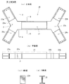
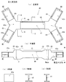
- FIG. 6 shows a first embodiment of the basic unit of the present invention.
- A is a front view
- (b) is a plan view
- (c) is an A sectional view of (a)
- (d) is a B sectional view of (a).
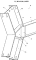
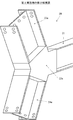
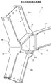
- FIG. 7 is a partial perspective view of the first embodiment.
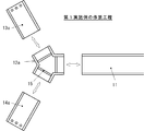
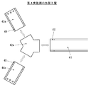
- FIG. 8 is a diagram for explaining an example of the manufacturing process of the first embodiment.
- each of the beam portion 11, the first upper oblique column portion 13a, the first lower oblique column portion 14a, the second upper oblique column portion 13b, and the second lower oblique column portion 14b is made of H-section steel. ing. Moreover, the 1st rigid region part 12a and the 2nd rigid region part 12b are produced so that it may correspond with the end surface of the H-section steel of a beam part and an oblique column part.
- the symbol P indicates a bent portion that is a boundary between the upper oblique column portion and the beam portion, a boundary between the lower oblique column portion and the beam portion, and a boundary between the upper oblique column portion and the lower oblique column portion.
- Reference numeral 16 denotes a bolt hole used for joining with another basic unit. (The same applies to the following examples)
- each reinforcing steel material 15 is plate-shaped, inserted into a space surrounded by the flange and the web, and welded thereto. The same applies to the second rigid region 12b.
- the rigid regions 12a and 12b can be further strengthened. The strength can be adjusted by the material and thickness of the reinforcing steel material 15.
- the first rigid region portion 12 a is produced, and then each end face of the three short leg portions of the first rigid region portion 12 a and the beam portion 11.
- the H-shaped steel end surfaces of the first upper oblique column portion 13a and the first lower oblique column 14a are welded and integrated.
- FIG. 9 shows a second embodiment of the basic unit of the present invention.
- (A) is a front view
- (b) is a plan view
- (c) is an A sectional view of (a)
- (d) is a B sectional view of (a).
- FIG. 10 is a partial perspective view of the second embodiment.
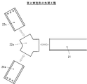
- FIG. 11 is a diagram for explaining an example of the manufacturing process of the second embodiment.
- each of the beam portion 21, the first upper oblique column portion 23a, the first lower oblique column portion 24a, the second upper oblique column portion 23b, and the second lower oblique column portion 24b is made of H-section steel. ing. As shown to Fig.9 (a) and (c), the 1st rigid region part 12a and the 2nd rigid region part 12b are produced with the solid steel material.
- the first rigid region 22a which is a solid steel material, is produced in a predetermined shape, and then the three short legs of the first rigid region 22a.
- Each end face of the portion is welded and integrated with each end face of the H-shaped steel of the beam portion 21, the first upper oblique column portion 23a, and the first lower oblique column 24a.
- FIG. 12 shows a third embodiment of the basic unit of the present invention.
- (A) is a front view
- (b) is a plan view
- (c) is an A sectional view of (a)
- (d) is a B sectional view of (a)
- (e) is a C sectional view of (a). is there.
- FIG. 13 is a partial perspective view of the third embodiment.
- FIG. 14 is a diagram for explaining an example of the manufacturing process of the third embodiment.
- each of the beam portion 31, the first upper oblique column portion 33a, the first lower oblique column portion 34a, the second upper oblique column portion 33b, and the second lower oblique column portion 34b is made of H-section steel. ing. Moreover, the 1st rigid region part 32a and the 2nd rigid region part 32b are produced so that it may correspond with the end surface of the H-section steel of a beam part and an oblique column part. As in the first embodiment, a reinforcing steel material 35 is provided in each of the rigid regions 32a and 32b.
- the feature of the third embodiment is that the dimensions of the basic unit 30 in the prospective direction are changed according to the magnitude of the stress borne by each part. .
- the maximum dimension Wmax is set in each of the rigid regions 32a and 32b where the maximum stress is applied. This strengthens each rigid region.
- the second dimension W2 is smaller than the maximum dimension Wmax.
- the third dimension W3 is smaller than the maximum dimension Wmax.
- the third dimension W3 is made equal to the second dimension W2 or smaller than the second dimension W2.
- a tapered portion 38 that gradually changes from the maximum dimension Wmax to the second dimension W2 is provided between each of the rigid region portions 32a and 32b and the midpoint M1 of the beam portion 31.
- a tapered portion 39 that gradually changes from the maximum dimension Wmax to the third dimension W3 is provided between each rigid region portion 32a, 32b and the end portion M2, M4 of each upper oblique column portion 33a, 33b. .
- taper portions 39 that gradually change from the maximum dimension Wmax to the third dimension W3 are also provided between the rigid regions 32a and 32b and the ends M3 and M5 of the lower oblique column portions 34a and 34b, respectively.
- the dimension in a prospective direction is changing continuously. Thereby, the intensity
- the axial lengths of the tapered portions 38 and 39 are set as appropriate.
- the first rigid region portion 32a is produced in a predetermined shape, and then each end face of the three short leg portions of the first rigid region portion 32a
- the beam portion 31, the first upper oblique column portion 33a and the first lower oblique column 34a are welded and integrated with the respective end faces of the H-shaped steel.
- FIG. 15 shows a fourth embodiment of the basic unit of the present invention.
- (A) is a front view
- (b) is a plan view
- (c) is an A sectional view of (a)
- (d) is a B sectional view of (a)
- (e) is a C sectional view of (a). is there.
- FIG. 16 is a partial perspective view of the fourth embodiment.
- FIG. 17 is a diagram for explaining an example of the manufacturing process of the fourth embodiment.
- each of the beam portion 41, the first upper oblique column portion 43a, the first lower oblique column portion 44a, the second upper oblique column portion 43b, and the second lower oblique column portion 44b is made of H-section steel. ing.
- the first rigid region portion 42a and the second rigid region portion 42b are made of a solid steel material.
- the feature of the fourth embodiment is that the size of the basic unit 40 in the prospective direction depends on the magnitude of the stress borne by each part, as in the third embodiment. It is a point that is changed.
- each rigid zone part 42a, 42b it is set as the maximum dimension Wmax
- in the middle point M1 of the beam part 41 it is set as the 2nd dimension W2 smaller than the maximum dimension Wmax
- the third dimension W3 is smaller than the maximum dimension Wmax.
- a tapered portion 48 that gradually changes from the maximum dimension Wmax to the second dimension W2 and a tapered portion 49 that gradually changes from the maximum dimension Wmax to the third dimension W3 are provided. These are the same as in the third embodiment.
- the first rigid region 42a which is a solid steel material, is produced in a predetermined shape, and then the three short legs of the first rigid region 42a.
- Each end surface of the part is welded to each end surface of the H-shaped steel of the beam portion 41, the first upper oblique column portion 43a, and the first lower oblique column 44a to be integrated.
- FIG. 18 to 20 show another embodiment of the basic unit.
- FIG. 18 shows a fifth embodiment of the basic unit of the present invention.
- (A) is a front view
- (b) is a plan view.
- the basic unit 50 of the fifth embodiment is an embodiment in which the reinforcing steel material 35 is not provided in the basic unit 30 of the third embodiment shown in FIG. In each rigid region portion in this embodiment, the rigid region is secured by increasing the size in the prospective direction without using a reinforcing steel material.
- FIG. 19 shows a sixth embodiment of the basic unit of the present invention and shows only a front view.
- the basic unit 60 of the sixth embodiment is an embodiment in which the reinforcing steel member 35 is not provided in the basic unit 30 of the first embodiment shown in FIG. In this case, it is strengthened by expanding the shape of each rigid region.
- the size in the prospective direction may be changed as in the third embodiment.
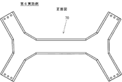
- FIG. 20 shows a seventh embodiment of the basic unit of the present invention and shows only a front view.
- the basic unit 70 of the seventh embodiment is an embodiment in which the shape of each rigid region portion in front view is enlarged in the basic unit 20 of the second embodiment shown in FIG. In this case, it is strengthened by expanding the shape of each rigid region that is a solid steel material.
- the size in the prospective direction may be changed as in the fourth embodiment.
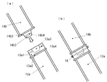
- FIG. 21A shows an embodiment of a joining means for joining two basic units.
- the first upper oblique column portion 13a of the lower basic unit and the second lower oblique column portion 14b of the upper basic unit are brought into contact with each other, and the gusset plate 17 is attached to both. Apply it so that it straddles, and fix with bolts 18 and nuts.
- FIG. 21B shows another embodiment of a joining means for joining two basic units.
- the solid steel material 13a1 is welded to the edge part of the 1st upper oblique column part 13a of the lower basic unit via the welding plate 13a2.
- a recess 13a3 and a bolt hole 13a4 are formed in the solid steel material 13a1.
- a solid steel material 14a3 is welded to the end portion of the second lower oblique column portion 14b of the upper basic unit via a welding plate 14a2.
- Bolt holes 14b4 are formed in the solid steel material 14a3.
- the solid steel material 14a3 is fitted into the recess 13a3 of the solid steel material 13a1, and the bolts 18 are passed through both sides and fixed with nuts.
- the means for joining the two basic units may have various modifications other than the means shown in FIGS. 21A and 21B.
- H-section steel is used as the steel material for the beam portion and each oblique column portion, but shape steels having various cross-sectional shapes may be used instead of the H-section steel. Further, steel pipes having various cross-sectional shapes such as square steel pipes may be used instead of H-section steel.
- a honeycomb structure using the basic unit of the present invention different types may be combined. For example, in the lower floor, a basic unit having a relatively high yield strength in the rigid zone is used, and in the upper story, a basic unit having a relatively small yield strength in the rigid zone is used.
- the two basic units can be joined even if the shapes of the other portions are different as long as the shapes of the end portions of the oblique column portions to be joined to each other match.
Landscapes
- Engineering & Computer Science (AREA)
- Architecture (AREA)
- Physics & Mathematics (AREA)
- Electromagnetism (AREA)
- Civil Engineering (AREA)
- Structural Engineering (AREA)
- Joining Of Building Structures In Genera (AREA)
- Rod-Shaped Construction Members (AREA)
Abstract
【課題】現場での施工性がよくかつ六角形フレームの頂点において剛域を形成できるハニカム構造体構築用の基本ユニット及びこれを用いたハニカム構造体の施工方法を提供する。 【解決手段】ハニカム建築構造体(100)を構築するために用いられる基本ユニット(U)であって、構造部材から形成され、六角形フレームにおける1つの水平辺の各端部を形成する第1及び第2の剛域部(2a,2b)、その間の部分を形成する梁部(1)と、各剛域部から斜め上方及び斜め下方に延び各斜辺の中点までの部分を形成する4つの斜柱部(3a,4a,3b,4b)とを備え、2つの基本ユニットを鉛直方向に積み上げた場合に、下側に位置する基本ユニットの上斜柱部と、上側に位置する基本ユニットの下斜柱部とが接合可能である。
Description
本発明は、ハニカム建築構造体を構築するための基本ユニット、並びに、当該基本ユニットを用いた施工方法に関する。
本出願人は、既に特許文献1~5に開示されたハニカム建築構造体(以下、”ハニカム構造体”と略称する)を提示している。これらの文献におけるハニカム構造体は、好適には、チューブ架構に適用される。
図22の(a)は、チューブ架構を形成するハニカム構造体の一例を示している(特許文献1に開示)。なお、この図は、ハニカム構造体の全体形状を示すための概略図である。実際の建築構造体は、柱や梁となる個々の構造部材を接合して構築されるが、この図では、個々の構造部材の形状及び部材同士の接合箇所は、具体的に示していない。
このハニカム構造体は、メインフレームであり、建物全体の長期負荷(固定荷重+積載荷重)を負担する最も重要な骨格である。図22の(b)は、ハニカム構造体100の単位構造である六角形フレームを示している。1つの六角形フレームは、上下一対の水平辺101と、左右二対の斜辺102とを有する。ハニカム構造体100においては、隣り合う六角形フレームが1つの辺部材を共有しており、これによりハニカム形状を形成している。
ハニカム構造体100における梁は、六角形フレームの水平辺101に相当し、水平方向に連続していない。また、柱は、六角形フレームの左右の斜辺102に相当し、鉛直方向にジグザグに連続する斜柱となる。このようなハニカム構造体は、様々な方向から建築物に加わる負荷を、梁又は斜柱の軸力に変換しやすいという長所がある。加えて、ハニカム形状特有の剛性を有することにより、チューブ架構のみによって建築物全体の構造的安定性と耐震性を確保することができる。構造解析の結果からも、ハニカム構造のチューブ架構は、一般ラーメン構造のチューブ架構に比べて同じ水平荷重に対する変形及び曲げモーメントの応力が小さいことが確認された。つまり、同じ量の変形及び曲げモーメントの応力に対する強度を確保する場合に、ハニカム構造では、一般ラーメン構造に比べて梁及び柱を細くできる。加えて、チューブ架構の内部に補強構造がなくとも十分な強度が得られるため、自由な内部空間を十分確保できる。
また、ハニカム構造体における水平荷重(地震力等)に対する曲げモーメントの応力は、六角形フレームの各頂点において最大となり、各辺の中点において最小となることことも、構造解析から判明している。このことは、各頂点に配置される構造部材には十分な耐力が必要であることを意味する。一方、各辺の中点は、比較的耐力が必要とされないため、構造部材同士の接合点として適しているといえる。
ハニカム構造体は、ほぼ同じ形状の複数の構造部材すなわち基本ユニットを、同じ規則性に従って接合していくことにより構築することができる。図22の(a)に示したハニカム構造体の基本ユニットとしては、例えば、特許文献3(図1)に開示された三股形ユニットがある。三股形ユニットは、中心から放射状に延びる3本の脚部を有する形状である。三股形ユニットの中心は六角形フレームの頂点に配置され、3本の脚部はこの頂点から延びる3つの辺の中点までをそれぞれ占めるように配置される。三股形ユニット同士の接合は、六角形フレームの各辺の中点で行われる。
ハニカム構造体を構築するためは、ほぼ同じ形状及び同じ特性をもつ基本ユニットを多数必要とするので、高度な品質管理の下で工場生産することが好ましい。そして、工場生産された基本ユニットを現場に搬入し、現場では、基本ユニット同士の接合のみを行う施工方法となる。
しかしながら、現場において三股形ユニットをクレーンで1つずつ吊り上げ、積み上げ、接合していく場合、1つの三股形ユニットは左右非対称であるために、正しい向きを維持しつつ支持することが難しい。また、吊り上げた2つの三股形ユニットは不安定であるため、双方の水平辺同士を空中で接合すること困難である。従って、先ず、2つの三股形ユニットを地上に寝かせた状態で水平辺同士を接合して左右対称な形状とする必要がある。その後、互いに接合した2つのユニットをクレーンで吊り、鉛直方向に積上げ、順次接合していく。この結果、現場での作業負担が多大となり、基本ユニットを工場生産することによる施工効率が損なわれてしまう。また、現場での接合作業は、工場で行う場合に比べて十分な品質管理ができないため、接合強度が不足したり不均一となったりするおそれがある。よって現場での接合作業は、最小限とすることが望ましい。
本発明は、ハニカム構造体を構築するための基本ユニットであって、現場での施工性がよく、かつ、応力負荷の大きい六角形フレームの頂点において十分な耐力を有する基本ユニットを提供することを目的とする。また、この基本ユニットを用いたハニカム構造体の施工方法を提供することを目的とする。
上記の目的を達成する本発明の構成は、以下の通りである。
本発明による基本ユニットにより構築されるハニカム構造体は、各六角形フレームが上下一対の水平辺と左右二対の斜辺とを有しかつ隣り合う2つの六角形フレームが互いに一辺を共有する複数の六角形フレームから形成された構造を有している。
本発明による基本ユニットにより構築されるハニカム構造体は、各六角形フレームが上下一対の水平辺と左右二対の斜辺とを有しかつ隣り合う2つの六角形フレームが互いに一辺を共有する複数の六角形フレームから形成された構造を有している。
基本ユニットの基本態様は、構造部材から形成され、前記六角形フレームの1つの水平辺の各端部をそれぞれ形成する第1の剛域部及び第2の剛域部と、前記第1の剛域部と前記第2の剛域部の間の部分を形成する梁部と、前記第1の剛域部から斜め上方及び斜め下方にそれぞれ延び前記六角形フレームの2つの斜辺の各中点までの部分を形成する第1の上斜柱部及び第1の下斜柱部と、前記第2の剛域部から斜め上方及び斜め下方にそれぞれ延び前記六角形フレームの別の2つの斜辺の各中点までの部分を形成する第2の上斜柱部及び第2の下斜柱部と、を備え、下側に位置する1つの基本ユニットの第1の上斜柱部に対して、上側に位置する別の基本ユニットの第2の下斜柱部が接合可能であり、かつ、該下側に位置する1つの基本ユニットの第2の上斜柱部に対して、上側に位置するさらに別の基本ユニットの第1の下斜柱部が接合可能である。
基本ユニットの一実施態様においては、前記構造部材が構造用鋼材であり、前記第1及び第2の剛域部の各々が補強鋼材をそれぞれ付設されている。
基本ユニットの別の実施態様においては、前記構造部材が構造用鋼材であり、前記第1及び第2の剛域部の各々が中実鋼材からそれぞれ形成され、かつ、前記第1及び第2の剛域部以外の部分が形鋼または鋼管から形成されている。
基本ユニットのさらに別の実施態様においては、前記構造部材が構造用鋼材であり、見込み方向における前記基本ユニットの寸法が、前記第1及び第2の剛域部において最大寸法であり、前記梁部の中点において該最大寸法よりも小さい第2の寸法であり、かつ前記第1及び第2の上斜柱部の端部並びに前記第1及び第2の下斜柱部の端部において該最大寸法よりも小さい第3の寸法である。
基本ユニットのさらに別の実施態様においては、見込み方向における前記基本ユニットの寸法が、記最大寸法と、第2の寸法と、第3の寸法とを有する場合に、前記第1及び第2の剛域部の各々と前記梁部の中点との間において、前記最大寸法から前記第2の寸法へと漸次変化する第1のテーパー部がそれぞれ設けられ、かつ、前記第1及び第2の剛域部の各々と前記第1及び第2の上斜柱部の端部との間、並びに、前記第1及び第2の剛域部の各々と前記第1及び第2の下斜柱部の端部との間において、前記最大寸法から前記第3の寸法へと漸次変化する第2のテーパー部がそれぞれ設けられている。
上記基本ユニットを用いてハニカム構造体を構築するための施工方法は、複数の基本ユニットを、鉛直方向に積上げ、接合する工程を有し、前記工程においては、下側に位置する1つの基本ユニットの第1の上斜柱部に対して、上側に位置する別の基本ユニットの第2の下斜柱部が接合されるとともに、該下側に位置する1つの基本ユニットの第2の上斜柱部に対して、上側に位置するさらに別の基本ユニットの第1の下斜柱部が接合される。
本発明による基本ユニットは、六角形フレームの水平辺の各端部が第1の剛域部及び第2の剛域部梁部により形成されている。2つの剛域部の間の部分が梁部である。第1の剛域部からは斜め上方及び斜め下方にそれぞれ第1の上斜柱部及び第1の下斜柱部が延びている。第2の剛域部からは斜め上方及び斜め下方にそれぞれ第2の上斜柱部及び第2の下斜柱部が延びている。従って、1つの基本ユニットは、基本的に左右対称形状である。1つの基本ユニットは、ハニカム構造体の六角形フレームにおける1つの水平辺の部分と、その両端からそれぞれ上方と下方へ延びる4つの斜辺の各中点までの部分を形成することができる。
本発明による施工方法は、複数の基本ユニットを鉛直方向に積上げ、接合することによりハニカム構造体を構築するものである。基本ユニットは、左右対称形状であるので、現場に搬入した後、直ちにクレーンによる吊り上げ作業を開始できる。左右対称形状であるので、空中でも正しい向きに維持すること、特に梁部を水平に維持することが容易である。この結果、空中での接合作業を安定に行うことができる。また、本発明による施工方法における作業は、上下に位置する2つの基本ユニットの斜柱部の端部同士を接合する一種類の作業のみであるので、作業が簡易である。
このように本発明による基本ユニットを用いた施工方法は、極めて施工性がよいという利点がある。この結果、良好かつ均一な接合状態を実現できる。
このように本発明による基本ユニットを用いた施工方法は、極めて施工性がよいという利点がある。この結果、良好かつ均一な接合状態を実現できる。
本発明による基本ユニットは、工場生産に適しており、高度な品質管理により、同じ特性をもつ基本ユニットを量産できる。現場で接合される箇所は、基本ユニットにおける4つの斜柱部の各端部のみである。これらの接合箇所は、ハニカム構造体における六角形フレームの斜辺の中点に対応する。六角形フレームの斜辺の中点は、ハニカム構造体において最も曲げモーメントの応力が小さい箇所である。従って、この箇所での接合には、比較的強度が要求されず、ピン接合で十分である。ピン接合のための作業は、剛接合のための作業に比べて簡易であるため、現場で行う負担が少ない。また、接合状態についても高度な品質管理が不要である。
本発明による基本ユニットは、全体が1つの一体的な構造部材である。第1及び第2の剛域部は、それぞれ梁部と2つの斜柱部の3方向に分岐する基部である。各剛域部は、本来的に剛接合となっており、剛域を形成している。ここで、”本来的に”とは、”基本ユニットの作製完了時点で”という意味である。
2つの剛域部の位置は、ハニカム構造体の六角形フレームの頂点位置である。この頂点位置は、ハニカム構造体において最も曲げモーメントの応力が大きい箇所である。従って、本発明の基本ユニットでは、最も耐力を要求される箇所が本来的に剛域となっている。
また、六角形フレームの水平辺の中点は、頂点に比べれば曲げモーメントの応力は小さいが、斜辺の中点に比べれば大きい。基本ユニットは一体的な構造部材であるから、この梁部の中点にも本来的に接合部はなく、剛性が確保されている。
以上により、本発明の基本ユニットを用いて構築されたハニカム構造体においては、曲げモーメント応力が最小となる箇所のみが現場接合され、それ以外の部分は一体的な構造部材であり剛性が確保されている、ということができる。よって、本発明の基本ユニットは、ハニカム構造体を構築するためのユニットとして、構造耐力上最適な形状であるといえる。
さらに、本発明の基本ユニットが構造用鋼材である場合、2つの剛域部にそれぞれ補強鋼材を設けることにより、この剛域をさらに強化することができる。あるいは、2つの剛域部をそれぞれ中実鋼材とすることによっても、同様の効果が得られる。この結果、ハニカム構造体における曲げモーメントの応力の最大箇所に要求される耐力を実現できる。
また、負担する応力の大きさに応じて、見込み方向における基本ユニットの寸法を変化させることも有効である。2つの剛域部において見込み方向の寸法を最大寸法とし、梁部の中点、上斜柱部の端部及び下斜柱部の端部においてはこの最大寸法よりも小さい寸法とする。さらに、最大寸法の箇所と、より小さい寸法の箇所との間に、漸次寸法の変化するテーパー部を設けることも好適である。このように、各箇所の曲げモーメントの応力の大きさに応じて、最適な耐力を設計することができる。
上記のように、大きな応力の掛かる箇所においては材料の量を多くして耐力を強化し、比較的応力の小さい箇所においては材料の量を少なくするという手法は、材料を効率的に利用し、省資源化を図り、コスト低減するという効果もある。
図1は、本発明の基本ユニットを用いて構築された、チューブ架構を形成するハニカム構造体の一実施例(図22と同形状)を示している。ハニカム構造体100は、メインフレームであり、建物全体の長期負荷(固定荷重+積載荷重)を負担する最も重要な骨格である。このハニカム構造体100は、水平断面形状が略四角形であり、立設された4つの平坦な側面を有する。図1中に、用いられた基本ユニットU及びU1をそれぞれ取り出し、例示している。基本ユニットUは、平坦側面部を形成するための基本ユニットであり、基本ユニットU1は、四隅の屈曲部を形成するための基本ユニットである。
図2は、本発明の基本ユニットを用いて構築された、チューブ架構を形成するハニカム構造体の別の実施例を示している。このハニカム構造体101は、水平断面形状が略円形であり、立設された略円筒状の側面部及びドーム状の天頂部を有する。図2中に、用いられた基本ユニットU2及びU3をそれぞれ取り出し、例示している。基本ユニットU2は、円筒側面部を形成するための基本ユニットであり、基本ユニットU3は、ドーム面を形成するための基本ユニットである。天頂部には、さらに別の変形ユニットが用いられている。
図3は、本発明による基本ユニットの基本形態を示している。(a)は、ハニカム構造体の平坦部分を形成するために用いられる基本ユニットUの一実施例の正面図であり、(b)はその平面図である。(c)は、ハニカム構造体の屈曲部分または湾曲部分を形成するために用いられる基本ユニットU1、U2、U3の一実施例の正面図であり、(d)はその平面図である。
図3(a)の正面図に示す平坦部用の基本ユニットUは、第1剛域部2a及び第2剛域部2bを備え、これら2つの剛域部の間が梁部1となっている。さらに、第1剛域部2aから斜め上方には第1上斜柱部3aが、そして斜め下方には第1下斜柱部4aが、それぞれ延びている。第2剛域部2bから斜め上方には第2上斜柱部3bが、そして斜め下方には第2下斜柱部4bが、それぞれ延びている。基本ユニットUは、正面視において左右対称形状である。
第1剛域部2aは、梁部1と第1上斜柱部3aと第1下斜柱部4aの3方向に分岐する基部である。第2剛域部2bは、梁部1と第2上斜柱部3bと第2下斜柱部4bの3方向に分岐する基部である。第1剛域部2a及び第2剛域部2bの範囲を規定する明確な境界はないが、図中に点線で示した範囲が、ほぼ該当する。
図3(b)の平面図に示すように、平坦部用の基本ユニットUでは、梁部1と上斜柱部3a、3bと下斜柱部4a、4bとが直線状に延びている。
図3(c)の正面図に示す屈曲部用または湾曲部用の基本ユニットU1、U2、U3は、2つの剛域部2a、2bと、梁部1と、4つの斜柱部3a、4a、3b、4bとを備えている点は、基本ユニットUと同じである。
図3(d)の平面図に示すように、屈曲部用または湾曲部用の基本ユニットU、U2、U3は、梁部1に対して上斜柱部3a、3b及び下斜柱部4a、4bがそれぞれ所定の角度をなして延びている。図示の例では、左右の斜柱部が梁部に対して同じ方向に曲がっているが、別の例として左右の斜柱部が梁部に対して異なる方向に曲がっていてもよい。
平坦部用、屈曲部用または湾曲部用の基本ユニットを組み合わせることにより、多様な形状の立設されたハニカムフレームを形成することができる。
本発明による基本ユニットは、全体が1つの一体的な構造部材である。この場合の”一体的”とは、例えば、複数の鋼材部品を溶接して一体化する場合も含む。
図4A及び図4Bを参照して、本発明の基本ユニットの基本原理を説明する。
図4Aは、ハニカム構造体100の単位構造である六角形フレームHと、基本ユニットUとの関係を模式的に示す正面図である。六角形フレームHの各々は、対向する一対の水平辺h1及びh4、対向する左右一対の斜辺h2及びh5、別の対向する左右一対の斜辺h3及びh6からなる6つの辺部材を有する。さらに、隣り合う2つの六角形フレームHは、1つの辺部材を共有している。複数の六角形フレームHは、ハニカム形状を形成している。六角形フレームHは、基本的には正面視において上下対称かつ左右対称な六角形である。しかしながら、例えば図2のように、上方へ向かって次第に細くなる円筒部分や、ドーム部分では、上下対称でない形態や、上下対称でも左右対称でもない変形形態もあり得る。このような変形形態であっても、少なくとも隣の基本ユニットと接合可能であればよい。
図4Aは、ハニカム構造体100の単位構造である六角形フレームHと、基本ユニットUとの関係を模式的に示す正面図である。六角形フレームHの各々は、対向する一対の水平辺h1及びh4、対向する左右一対の斜辺h2及びh5、別の対向する左右一対の斜辺h3及びh6からなる6つの辺部材を有する。さらに、隣り合う2つの六角形フレームHは、1つの辺部材を共有している。複数の六角形フレームHは、ハニカム形状を形成している。六角形フレームHは、基本的には正面視において上下対称かつ左右対称な六角形である。しかしながら、例えば図2のように、上方へ向かって次第に細くなる円筒部分や、ドーム部分では、上下対称でない形態や、上下対称でも左右対称でもない変形形態もあり得る。このような変形形態であっても、少なくとも隣の基本ユニットと接合可能であればよい。
基本ユニットUの第1剛域部2a及び第2剛域部2bは、六角形フレームHにおける1つの水平辺の各端部すなわち頂点C1、C2の部分を形成する。
梁部1は、1つの水平辺h1の部分、すなわち第1剛域部2aと第2剛域部2bの間の部分を形成する。
第1上斜柱部3aは、第1剛域部2aから斜め上方に延びる斜辺h2の中点M2までの部分を形成する。
第1下斜柱部4aは、第1剛域部2aから斜め下方に延びる斜辺h3の中点M3までの部分を形成する。
第2上斜柱部3bは、第2剛域部2bから斜め上方に延びる斜辺h6の中点M4までの部分を形成する。
第2下斜柱部4bは、第2剛域部2bから斜め下方に延びる斜辺h5の中点M5までの部分を形成する。
梁部1は、1つの水平辺h1の部分、すなわち第1剛域部2aと第2剛域部2bの間の部分を形成する。
第1上斜柱部3aは、第1剛域部2aから斜め上方に延びる斜辺h2の中点M2までの部分を形成する。
第1下斜柱部4aは、第1剛域部2aから斜め下方に延びる斜辺h3の中点M3までの部分を形成する。
第2上斜柱部3bは、第2剛域部2bから斜め上方に延びる斜辺h6の中点M4までの部分を形成する。
第2下斜柱部4bは、第2剛域部2bから斜め下方に延びる斜辺h5の中点M5までの部分を形成する。
図4Bは、ハニカム構造体100における水平荷重に対する曲げモーメントの応力と、基本ユニットUとの関係を模式的に示す図である。図中のグラフの横軸は、基本ユニットUの右半分の軸方向に沿った距離を示し、縦軸は、曲げモーメントの応力の大きさの相対変化を示している。基本ユニットUは左右対称であるので、左半分についても右半分と同様となる。
図4Bのグラフに示すように、ハニカム構造体100における曲げモーメントの応力は、六角形フレームの頂点C2において最大となる。
そして、曲げモーメントの応力は、六角形フレームの頂点C2から水平辺の中点M1へ向かって減少する。1つの水平辺上の応力は、中点M1で極小となる。
また、曲げモーメントの応力は、六角形フレームの頂点C2から斜辺の中点M4へ向かって減少する。1つの斜辺上の応力は、中点M4で極小となる。
さらに、グラフに示すように、斜辺の中点M4における曲げモーメントの応力は、水平辺の中点M1におけるそれよりも小さい。よって、ハニカム構造体100における曲げモーメントの応力は、斜辺の中点M4において最小となる。
そして、曲げモーメントの応力は、六角形フレームの頂点C2から水平辺の中点M1へ向かって減少する。1つの水平辺上の応力は、中点M1で極小となる。
また、曲げモーメントの応力は、六角形フレームの頂点C2から斜辺の中点M4へ向かって減少する。1つの斜辺上の応力は、中点M4で極小となる。
さらに、グラフに示すように、斜辺の中点M4における曲げモーメントの応力は、水平辺の中点M1におけるそれよりも小さい。よって、ハニカム構造体100における曲げモーメントの応力は、斜辺の中点M4において最小となる。
以上によれば、基本ユニットUにおいては、2つの剛域部2a、2bに掛かる応力が最大であり、4つの斜柱部3a、3b、4a、4bの端部に掛かる応力が最小ということになる。従って、基本ユニットUは、2つの剛域部において最も耐力が要求されることになる。基本ユニットUは一体的な構造部材であるので、2つの剛域部2a、2bは本来的に剛接合であり、本来的に剛域が形成されている。ここで、”本来的に”とは、”基本ユニットUの作製完了時点で”という意味である。よって、剛域部2a、2bは、高い耐力を有している。
そして、2つの基本ユニットU同士の接合は、曲げモーメントの応力が最小となる箇所、すなわち各斜柱部の端部で行われる。この部分にかかる応力は比較的小さいため、通常、ピン接合でよい。この接合は施工現場で行われ、そして、現場接合されるのはこの箇所のみである。
このように、本発明の基本ユニットは、ハニカム構造体の応力分布に最適に適応した形状を本来的に有している。
図5は、本発明の基本ユニットを用いてハニカム構造体を構築する施工方法を説明する図である。図5のハニカム構造体100は、図1に示したものの一部である。平坦部分を形成する基本ユニットUと、隅部を形成する基本ユニットU1を用いている。各基本ユニットU、U1は、梁部を水平にしてクレーンで吊り上げられ、既に接合作業の完了している下段の基本ユニットの上に積み上げられる。その後、下段の基本ユニットとの接合作業が行われる。
図5を参照すると、ハニカム構造体100における相対的に上下に位置する2段のうち、下段を構成する1つの基本ユニットU-1の第1上斜柱部3aに対して、上段を構成する別の基本ユニットU-2の第2下斜柱部4bが接合される。そして下段の基本ユニットU-1の第2上斜柱部3bに対して、上段を構成するさらに別の基本ユニットU1-3の第1下斜柱部4aが接合される。
本発明の基本ユニットを用いた施工方法における作業は、上下に位置する2つの基本ユニットの斜柱部の端部同士を接合する一種類の作業のみであるので、複雑な手順はなく、極めて施工性がよい。この結果、高品質かつ均一な接合状態を実現することができる。
図6~図17に、本発明の基本ユニットの幾つかの実施例を示す。本発明の対象とするハニカム構造体は、好適には鉄骨造であるので、基本ユニットは、好適には構造用鋼材を用いて作製される。
図6は、本発明の基本ユニットの第1実施例である。(a)は正面図、(b)は平面図、(c)は(a)のA断面図、(d)は(a)のB断面図である。図7は、第1実施例の部分斜視図である。図8は、第1実施例の作製工程の一例を説明する図である。
基本ユニット10では、梁部11、第1上斜柱部13a、第1下斜柱部14a、第2上斜柱部13b及び第2下斜柱部14bの各々が、H形鋼で作製されている。また、第1剛域部12a及び第2剛域部12bは、梁部及び斜柱部のH形鋼の端面と合致するように作製されている。
符号Pは、上斜柱部と梁部の境界、下斜柱部と梁部の境界、及び上斜柱部と下斜柱部の境界である屈曲箇所を示している。符号16は、別の基本ユニットと接合するために用いるボルト孔である。(以下の実施例でも同様)
図6(a)及び(c)に示すように、第1剛域部12aの中央部分から放射状に突出する3つの短脚部分に、それぞれ補強鋼材15を設けることが好適である。各補強鋼材15は板状であり、フランジ及びウェブに囲まれた空間に挿入され、これらと溶接されている。第2剛域部12bについても同様である。これらの補強鋼材15を設けることにより、剛域部12a、12bをさらに強化できる。補強鋼材15の材質及び厚さにより強度を調節できる。
図8に示すように、基本ユニット10の作製においては、先ず、第1剛域部12aを作製し、次に、第1剛域部12aの3つの短脚部分の各端面と、梁部11、第1上斜柱部13a及び第1下斜柱14aのH型鋼の各端面とを溶接し、一体化する。図示しないが、第2剛域部も同様である。
図9は、本発明の基本ユニットの第2実施例である。(a)は正面図、(b)は平面図、(c)は(a)のA断面図、(d)は(a)のB断面図である。図10は、第2実施例の部分斜視図である。図11は、第2実施例の作製工程の一例を説明する図である。
基本ユニット20では、梁部21、第1上斜柱部23a、第1下斜柱部24a、第2上斜柱部23b及び第2下斜柱部24bの各々が、H形鋼で作製されている。図9(a)及び(c)に示すように、第1剛域部12a及び第2剛域部12bは、中実鋼材で作製されている。
図11に示すように、基本ユニット20の作製においては、先ず、中実鋼材である第1剛域部22aを所定の形状に作製し、次に、第1剛域部22aの3つの短脚部分の各端面と、梁部21、第1上斜柱部23a及び第1下斜柱24aのH型鋼の各端面とを溶接し、一体化する。図示しないが、第2剛域部も同様である。
図12は、本発明の基本ユニットの第3実施例である。(a)は正面図、(b)は平面図、(c)は(a)のA断面図、(d)は(a)のB断面図、(e)は(a)のC断面図である。図13は、第3実施例の部分斜視図である。図14は、第3実施例の作製工程の一例を説明する図である。
基本ユニット30では、梁部31、第1上斜柱部33a、第1下斜柱部34a、第2上斜柱部33b及び第2下斜柱部34bの各々が、H形鋼で作製されている。また、第1剛域部32a及び第2剛域部32bは、梁部及び斜柱部のH形鋼の端面と合致するように作製されている。各剛域部32a、32bには、第1実施例と同様に、補強鋼材35を設けている。
図12(b)の平面図に示すように、第3実施例の特徴は、各部位の負担する応力の大きさに応じて、見込み方向における基本ユニット30の寸法を変化させている点である。
最大応力の掛かる各剛域部32a、32bにおいては、最大寸法Wmaxとする。これにより各剛域部を強化する。
最大応力よりも小さい応力の掛かる梁部31の中点M1においては、最大寸法Wmaxよりも小さい第2の寸法W2とする。
最小応力の掛かる各斜柱部の端部M2、M4、M3及びM5においては、最大寸法Wmaxよりも小さい第3の寸法W3とする。第3の寸法W3は、第2の寸法W2と等しくするか、または、第2の寸法W2よりも小さくする。
最大応力の掛かる各剛域部32a、32bにおいては、最大寸法Wmaxとする。これにより各剛域部を強化する。
最大応力よりも小さい応力の掛かる梁部31の中点M1においては、最大寸法Wmaxよりも小さい第2の寸法W2とする。
最小応力の掛かる各斜柱部の端部M2、M4、M3及びM5においては、最大寸法Wmaxよりも小さい第3の寸法W3とする。第3の寸法W3は、第2の寸法W2と等しくするか、または、第2の寸法W2よりも小さくする。
さらに、各剛域部32a、32bと梁部31の中点M1との間には、最大寸法Wmaxから第2の寸法W2へと漸次変化するテーパー部38をそれぞれ設ける。
また、各剛域部32a、32bと各上斜柱部33a、33bの端部M2、M4との間には、最大寸法Wmaxから第3の寸法W3へと漸次変化するテーパー部39をそれぞれ設ける。
同様に、各剛域部32a、32bと各下斜柱部34a、34bの端部M3、M5との間にも、最大寸法Wmaxから第3の寸法W3へと漸次変化するテーパー部39をそれぞれ設ける。
これらのテーパー部38、39では、見込み方向における寸法が連続的に変化している。これにより、応力分布の連続的変化に応じて構造部材の強度を連続的に変化させることができる。テーパー部38、39の軸方向長さは適宜設定する。
また、各剛域部32a、32bと各上斜柱部33a、33bの端部M2、M4との間には、最大寸法Wmaxから第3の寸法W3へと漸次変化するテーパー部39をそれぞれ設ける。
同様に、各剛域部32a、32bと各下斜柱部34a、34bの端部M3、M5との間にも、最大寸法Wmaxから第3の寸法W3へと漸次変化するテーパー部39をそれぞれ設ける。
これらのテーパー部38、39では、見込み方向における寸法が連続的に変化している。これにより、応力分布の連続的変化に応じて構造部材の強度を連続的に変化させることができる。テーパー部38、39の軸方向長さは適宜設定する。
図14に示すように、基本ユニット30の作製においては、先ず、第1剛域部32aを所定の形状に作製し、次に、第1剛域部32aの3つの短脚部分の各端面と、梁部31、第1上斜柱部33a及び第1下斜柱34aのH型鋼の各端面とを溶接し、一体化する。図示しないが、第2剛域部も同様である。
図15は、本発明の基本ユニットの第4実施例である。(a)は正面図、(b)は平面図、(c)は(a)のA断面図、(d)は(a)のB断面図、(e)は(a)のC断面図である。図16は、第4実施例の部分斜視図である。図17は、第4実施例の作製工程の一例を説明する図である。
基本ユニット40では、梁部41、第1上斜柱部43a、第1下斜柱部44a、第2上斜柱部43b及び第2下斜柱部44bの各々が、H形鋼で作製されている。第1剛域部42a及び第2剛域部42bは、中実鋼材で作製されている。
図15(b)の平面図に示すように、第4実施例の特徴は、第3実施例と同様に、各部位の負担する応力の大きさに応じて、見込み方向における基本ユニット40の寸法を変化させている点である。
各剛域部42a、42bにおいては、最大寸法Wmaxとし、梁部41の中点M1においては、最大寸法Wmaxよりも小さい第2の寸法W2とし、各斜柱部の端部M2、M4、M3及びM5においては、最大寸法Wmaxよりも小さい第3の寸法W3とする。また、最大寸法Wmaxから第2の寸法W2へと漸次変化するテーパー部48、並びに、最大寸法Wmaxから第3の寸法W3へと漸次変化するテーパー部49をそれぞれ設ける。これらについての説明は、上記第3実施例と同様である。
各剛域部42a、42bにおいては、最大寸法Wmaxとし、梁部41の中点M1においては、最大寸法Wmaxよりも小さい第2の寸法W2とし、各斜柱部の端部M2、M4、M3及びM5においては、最大寸法Wmaxよりも小さい第3の寸法W3とする。また、最大寸法Wmaxから第2の寸法W2へと漸次変化するテーパー部48、並びに、最大寸法Wmaxから第3の寸法W3へと漸次変化するテーパー部49をそれぞれ設ける。これらについての説明は、上記第3実施例と同様である。
図17に示すように、基本ユニット40の作製においては、先ず、中実鋼材である第1剛域部42aを所定の形状に作製し、次に、第1剛域部42aの3つの短脚部分の各端面と、梁部41、第1上斜柱部43a及び第1下斜柱44aのH型鋼の各端面とを溶接し、一体化する。図示しないが、第2剛域部も同様である。
図18~図20を参照して、基本ユニットのその他の実施例を示す。
図18は、本発明の基本ユニットの第5実施例である。(a)は正面図、(b)は平面図である。第5実施例の基本ユニット50は、図13に示した第3実施例の基本ユニット30において補強鋼材35を設けない実施例である。この実施例における各剛域部では、補強鋼材なしで、見込み方向の寸法を大きくすることで剛域を確保している。
図18は、本発明の基本ユニットの第5実施例である。(a)は正面図、(b)は平面図である。第5実施例の基本ユニット50は、図13に示した第3実施例の基本ユニット30において補強鋼材35を設けない実施例である。この実施例における各剛域部では、補強鋼材なしで、見込み方向の寸法を大きくすることで剛域を確保している。
図19は、本発明の基本ユニットの第6実施例であり、正面図のみを示す。第6実施例の基本ユニット60は、図6に示した第1実施例の基本ユニット30において、補強鋼材35を設けず、各剛域部の正面視における形状を拡大した実施例である。この場合、各剛域部の形状を拡大することで強化している。図示しないが、この実施例の変形例として、第3実施例のように見込み方向の寸法を変化させてもよい。
図20は、本発明の基本ユニットの第7実施例であり、正面図のみを示す。第7実施例の基本ユニット70は、図9に示した第2実施例の基本ユニット20において、各剛域部の正面視における形状を拡大した実施例である。この場合、中実鋼材である各剛域部の形状を拡大することで強化している。図示しないが、この実施例の変形例として、第4実施例のように見込み方向の寸法を変化させてもよい。
以上述べた第1~第7の実施例以外にも、本発明の原理に沿った基本ユニットの多様な変形形態があり得る。それらの変形形態についても本発明に含まれるものとする。
図21Aは、2つの基本ユニットを接合する接合手段の実施例を示す。例えば、図6に示した第1実施例の場合、下段の基本ユニットの第1上斜柱部13aと、上段の基本ユニットの第2下斜柱部14bとを突き合わせ、ガセットプレート17を双方に跨るように当て、ボルト18とナットで固定する。
図21Bは、2つの基本ユニットを接合する接合手段の別の実施例を示す。(a)に示すように、下段の基本ユニットの第1上斜柱部13aの端部に、溶接用プレート13a2を介して中実鋼材13a1を溶接する。中実鋼材13a1には凹部13a3とボルト孔13a4が形成されている。一方、上段の基本ユニットの第2下斜柱部14bの端部には、溶接用プレート14a2を介して中実鋼材14a3が溶接されている。中実鋼材14a3にはボルト孔14b4が形成されている。(b)に示すように、中実鋼材13a1の凹部13a3に、中実鋼材14a3を嵌め込み、ボルト18を双方に貫通させてナットで固定する。
2つの基本ユニットの接合手段は、図21A及び図21Bに示した手段以外にも、多様な変形形態があり得る。
上述の基本ユニットの各実施例では、梁部及び各斜柱部の鋼材としてH形鋼を用いたが、H形鋼に替えて種々の断面形状をもつ形鋼を用いてもよい。また、H形鋼に替えて角形鋼管等の種々の断面形状をもつ鋼管を用いてもよい。
本発明の基本ユニットを用いてハニカム構造体を構築する場合、種類の異なる基本ユニットを組み合わせてもよい。例えば、下層階においては、剛域部の耐力が相対的に大きい基本ユニットを用い、上層階においては、剛域部の耐力が相対的に小さい基本ユニットを用いるようにする。2つの基本ユニットは、互いに接合する斜柱部の端部の形状が合致していれば、それ以外の部位の形状が異なっていても接合可能である。
U、U1、U2、U3、10、20、30、40、50、60、70 基本ユニット
1、11、21、31、41 梁部
2a、12a、22a、32a、42a 第1剛域部
2b、12b、22b、32b、42b 第2剛域部
3a、13a、23a、33a、43a 第1上斜柱部
3b、13b、23b、33b、43b 第2上斜柱部
4a、14a、24a、34a、44a 第1下斜柱部
4b、14b、24b、34b、44b 第2下斜柱部
15、35 補強鋼材
17 ガセットプレート
M1 水平辺(梁部)の中点
M2 斜辺の中点(第1上斜柱部の端部)
M3 斜辺の中点(第1下斜柱部の端部)
M4 斜辺の中点(第2上斜柱部の端部)
M5 斜辺の中点(第2下斜柱部の端部)
H 六角形フレーム
h1、h4 水平辺
h2、h3、h5、h6 斜辺
C1、C2 頂点
P 屈曲部
100、101 ハニカム構造体
1、11、21、31、41 梁部
2a、12a、22a、32a、42a 第1剛域部
2b、12b、22b、32b、42b 第2剛域部
3a、13a、23a、33a、43a 第1上斜柱部
3b、13b、23b、33b、43b 第2上斜柱部
4a、14a、24a、34a、44a 第1下斜柱部
4b、14b、24b、34b、44b 第2下斜柱部
15、35 補強鋼材
17 ガセットプレート
M1 水平辺(梁部)の中点
M2 斜辺の中点(第1上斜柱部の端部)
M3 斜辺の中点(第1下斜柱部の端部)
M4 斜辺の中点(第2上斜柱部の端部)
M5 斜辺の中点(第2下斜柱部の端部)
H 六角形フレーム
h1、h4 水平辺
h2、h3、h5、h6 斜辺
C1、C2 頂点
P 屈曲部
100、101 ハニカム構造体
Claims (6)
- 各六角形フレームが上下一対の水平辺と左右二対の斜辺とを有しかつ隣り合う2つの六角形フレームが互いに一辺を共有する複数の六角形フレームから形成されるハニカム建築構造体(100)を構築するために用いられる基本ユニット(U)であって、
構造部材から形成され、
前記六角形フレームの1つの水平辺の各端部をそれぞれ形成する第1の剛域部(2a)及び第2の剛域部(2b)と、
前記第1の剛域部(2a)と前記第2の剛域部(2b)の間の部分を形成する梁部(1)と、
前記第1の剛域部(2a)から斜め上方及び斜め下方にそれぞれ延び前記六角形フレームの2つの斜辺の各中点までの部分を形成する第1の上斜柱部(3a)及び第1の下斜柱部(4a)と、
前記第2の剛域部(2b)から斜め上方及び斜め下方にそれぞれ延び前記六角形フレームの別の2つの斜辺の各中点までの部分を形成する第2の上斜柱部(3b)及び第2の下斜柱部(4b)と、を備え、
下側に位置する1つの基本ユニットの第1の上斜柱部に対して、上側に位置する別の基本ユニットの第2の下斜柱部が接合可能であり、かつ、該下側に位置する1つの基本ユニットの第2の上斜柱部に対して、上側に位置するさらに別の基本ユニットの第1の下斜柱部が接合可能であることを特徴とする
ハニカム建築構造体の基本ユニット。 - 前記構造部材が構造用鋼材であり、
前記第1及び第2の剛域部(12a、12b)の各々が補強鋼材(15)をそれぞれ付設されていることを特徴とする
請求項1に記載のハニカム建築構造体の基本ユニット。 - 前記構造部材が構造用鋼材であり、
前記第1及び第2の剛域部(22a、22b)の各々が中実鋼材からそれぞれ形成され、かつ、
前記第1及び第2の剛域部(22a、22b)以外の部分が形鋼または鋼管から形成されていることを特徴とする
請求項1に記載のハニカム建築構造体の基本ユニット。 - 前記構造部材が構造用鋼材であり、
見込み方向における前記基本ユニットの寸法が、
前記第1及び第2の剛域部において最大寸法であり、前記梁部の中点において該最大寸法よりも小さい第2の寸法であり、かつ前記第1及び第2の上斜柱部の端部並びに前記第1及び第2の下斜柱部の端部において該最大寸法よりも小さい第3の寸法であることを特徴とする
請求項1~3のいずれかに記載のハニカム建築構造体の基本ユニット。 - 前記第1及び第2の剛域部の各々と前記梁部の中点との間において、前記最大寸法から前記第2の寸法へと漸次変化する第1のテーパー部がそれぞれ設けられ、かつ、
前記第1及び第2の剛域部の各々と前記第1及び第2の上斜柱部の端部との間、並びに、前記第1及び第2の剛域部の各々と前記第1及び第2の下斜柱部の端部との間において、前記最大寸法から前記第3の寸法へと漸次変化する第2のテーパー部がそれぞれ設けられていることを特徴とする
請求項4に記載のハニカム建築構造体の基本ユニット。 - 各六角形フレームが上下一対の水平辺と左右二対の斜辺とを有しかつ隣り合う2つの六角形フレームが互いに一辺を共有する複数の六角形フレームから形成されるハニカム建築構造体(100)を構築するための施工方法であって、
複数の基本ユニット(U)を、鉛直方向に積上げ、接合する工程を有し、
1つの前記基本ユニット(U)は、構造部材から形成され、かつ、前記六角形フレームの1つの水平辺の各端部をそれぞれ形成する第1の剛域部(2a)及び第2の剛域部(2b)と、
前記第1の剛域部(2a)と前記第2の剛域部(2b)の間の部分を形成する梁部(1)と、
前記第1の剛域部(2a)から斜め上方及び斜め下方にそれぞれ延び前記六角形フレームの2つの斜辺の各中点までの部分を形成する第1の上斜柱部(3a)及び第1の下斜柱部(4a)と、
前記第2の剛域部(2b)から斜め上方及び斜め下方にそれぞれ延び前記六角形フレームの別の2つの斜辺の各中点までの部分を形成する第2の上斜柱部(3b)及び第2の下斜柱部(4b)と、を備えており、
前記工程においては、下側に位置する1つの基本ユニットの第1の上斜柱部に対して、上側に位置する別の基本ユニットの第2の下斜柱部が接合されるとともに、該下側に位置する1つの基本ユニットの第2の上斜柱部に対して、上側に位置するさらに別の基本ユニットの第1の下斜柱部が接合されることを特徴とするハニカム建築構造体の施工方法。
Priority Applications (1)
| Application Number | Priority Date | Filing Date | Title |
|---|---|---|---|
| CN2009800000456A CN101939497B (zh) | 2009-03-11 | 2009-04-13 | 蜂巢式建筑结构体的基本单元及其施工方法 |
Applications Claiming Priority (2)
| Application Number | Priority Date | Filing Date | Title |
|---|---|---|---|
| JP2009-057614 | 2009-03-11 | ||
| JP2009057614A JP4365448B1 (ja) | 2009-03-11 | 2009-03-11 | ハニカム建築構造体の基本ユニット及びその施工方法 |
Publications (1)
| Publication Number | Publication Date |
|---|---|
| WO2010103577A1 true WO2010103577A1 (ja) | 2010-09-16 |
Family
ID=41443760
Family Applications (1)
| Application Number | Title | Priority Date | Filing Date |
|---|---|---|---|
| PCT/JP2009/001694 Ceased WO2010103577A1 (ja) | 2009-03-11 | 2009-04-13 | ハニカム建築構造体の基本ユニット及びその施工方法 |
Country Status (3)
| Country | Link |
|---|---|
| JP (1) | JP4365448B1 (ja) |
| CN (1) | CN101939497B (ja) |
| WO (1) | WO2010103577A1 (ja) |
Cited By (1)
| Publication number | Priority date | Publication date | Assignee | Title |
|---|---|---|---|---|
| GB2610429A (en) * | 2021-09-06 | 2023-03-08 | Stelling Modular Ltd | Metal-construction-beam connector system, construction module using said system, and a method of construction |
Families Citing this family (2)
| Publication number | Priority date | Publication date | Assignee | Title |
|---|---|---|---|---|
| CN103982005A (zh) * | 2014-04-15 | 2014-08-13 | 安徽富煌钢构股份有限公司 | 一种蜂窝形钢框架柱 |
| RU2643100C2 (ru) * | 2015-12-08 | 2018-01-30 | Михаил Юрьевич Ивановский | Строительный модуль для космических станций |
Citations (1)
| Publication number | Priority date | Publication date | Assignee | Title |
|---|---|---|---|---|
| WO2008142792A1 (ja) * | 2007-05-24 | 2008-11-27 | Sekisui Chemical Co., Ltd. | ハニカム建築構造体 |
Family Cites Families (1)
| Publication number | Priority date | Publication date | Assignee | Title |
|---|---|---|---|---|
| JP3811708B1 (ja) * | 2005-10-25 | 2006-08-23 | 積水化学工業株式会社 | 建築構造体 |
-
2009
- 2009-03-11 JP JP2009057614A patent/JP4365448B1/ja not_active Expired - Fee Related
- 2009-04-13 WO PCT/JP2009/001694 patent/WO2010103577A1/ja not_active Ceased
- 2009-04-13 CN CN2009800000456A patent/CN101939497B/zh not_active Expired - Fee Related
Patent Citations (1)
| Publication number | Priority date | Publication date | Assignee | Title |
|---|---|---|---|---|
| WO2008142792A1 (ja) * | 2007-05-24 | 2008-11-27 | Sekisui Chemical Co., Ltd. | ハニカム建築構造体 |
Cited By (1)
| Publication number | Priority date | Publication date | Assignee | Title |
|---|---|---|---|---|
| GB2610429A (en) * | 2021-09-06 | 2023-03-08 | Stelling Modular Ltd | Metal-construction-beam connector system, construction module using said system, and a method of construction |
Also Published As
| Publication number | Publication date |
|---|---|
| CN101939497B (zh) | 2012-02-22 |
| CN101939497A (zh) | 2011-01-05 |
| JP2010209600A (ja) | 2010-09-24 |
| JP4365448B1 (ja) | 2009-11-18 |
Similar Documents
| Publication | Publication Date | Title |
|---|---|---|
| JP4146511B1 (ja) | ハニカム建築構造体 | |
| JP2009249990A (ja) | 柱梁接合構造および柱梁接合方法 | |
| CN113107131A (zh) | 一种内环交汇的外悬挑大跨弧形变截面箱型钢梁结构及构成方法 | |
| CN105350658A (zh) | 卡槽装配式钢管柱和钢梁连接节点及其施工方法 | |
| CN214884850U (zh) | 内环交汇的外悬挑大跨弧形变截面箱型钢梁结构 | |
| CN105064512A (zh) | 圆钢管混凝土柱与钢梁的连接结构 | |
| JP5714136B2 (ja) | 円形ブレース及びその施工方法 | |
| JP4365448B1 (ja) | ハニカム建築構造体の基本ユニット及びその施工方法 | |
| JP2007120032A (ja) | 建築構造体 | |
| CN111962671B (zh) | 一种工字型梁柱强弱轴一体连接的装配式节点 | |
| WO2019092882A1 (ja) | 建築構造、建築物及び建築工法 | |
| KR20090067923A (ko) | 대각가새의 접합구조 | |
| CN113605541A (zh) | 一种外环式梁柱刚性连接节点 | |
| JP4772308B2 (ja) | ユニット建物の構築方法 | |
| US11680398B2 (en) | Strata space frame | |
| KR102223831B1 (ko) | 하이브리드 지붕 프레임 | |
| JP6784466B1 (ja) | ハニカム構造を使用した建築物のパネル | |
| CN108035441B (zh) | 一种建筑结构的双层错位桁架及其施工方法 | |
| JP2010255227A (ja) | 柱梁接合構造、及び、鉄筋コンクリート部材 | |
| JP3380600B2 (ja) | 建物の鉄骨構造 | |
| CN220203009U (zh) | 一种装配式登机设施用四向接驳构件 | |
| JP2017155510A (ja) | 柱梁接合部構造 | |
| CN207829162U (zh) | 一种建筑结构的双层错位桁架 | |
| CN117266365B (zh) | 一种双圈连拱梁型铝钢组合网壳结构及其施工方法 | |
| JP5283361B2 (ja) | 屋根架構の構築方法及び屋根架構 |
Legal Events
| Date | Code | Title | Description |
|---|---|---|---|
| WWE | Wipo information: entry into national phase |
Ref document number: 200980000045.6 Country of ref document: CN |
|
| 121 | Ep: the epo has been informed by wipo that ep was designated in this application |
Ref document number: 09841409 Country of ref document: EP Kind code of ref document: A1 |
|
| NENP | Non-entry into the national phase |
Ref country code: DE |
|
| 122 | Ep: pct application non-entry in european phase |
Ref document number: 09841409 Country of ref document: EP Kind code of ref document: A1 |