WO2010100779A1 - 電気接続箱 - Google Patents
電気接続箱 Download PDFInfo
- Publication number
- WO2010100779A1 WO2010100779A1 PCT/JP2009/066507 JP2009066507W WO2010100779A1 WO 2010100779 A1 WO2010100779 A1 WO 2010100779A1 JP 2009066507 W JP2009066507 W JP 2009066507W WO 2010100779 A1 WO2010100779 A1 WO 2010100779A1
- Authority
- WO
- WIPO (PCT)
- Prior art keywords
- lever
- connector
- fitted
- hood portion
- hood
- Prior art date
- Legal status (The legal status is an assumption and is not a legal conclusion. Google has not performed a legal analysis and makes no representation as to the accuracy of the status listed.)
- Ceased
Links
Images








Classifications
-
- H—ELECTRICITY
- H01—ELECTRIC ELEMENTS
- H01R—ELECTRICALLY-CONDUCTIVE CONNECTIONS; STRUCTURAL ASSOCIATIONS OF A PLURALITY OF MUTUALLY-INSULATED ELECTRICAL CONNECTING ELEMENTS; COUPLING DEVICES; CURRENT COLLECTORS
- H01R13/00—Details of coupling devices of the kinds covered by groups H01R12/70 or H01R24/00 - H01R33/00
- H01R13/62—Means for facilitating engagement or disengagement of coupling parts or for holding them in engagement
- H01R13/629—Additional means for facilitating engagement or disengagement of coupling parts, e.g. aligning or guiding means, levers, gas pressure electrical locking indicators, manufacturing tolerances
- H01R13/62933—Comprising exclusively pivoting lever
- H01R13/62938—Pivoting lever comprising own camming means
-
- H—ELECTRICITY
- H01—ELECTRIC ELEMENTS
- H01R—ELECTRICALLY-CONDUCTIVE CONNECTIONS; STRUCTURAL ASSOCIATIONS OF A PLURALITY OF MUTUALLY-INSULATED ELECTRICAL CONNECTING ELEMENTS; COUPLING DEVICES; CURRENT COLLECTORS
- H01R9/00—Structural associations of a plurality of mutually-insulated electrical connecting elements, e.g. terminal strips or terminal blocks; Terminals or binding posts mounted upon a base or in a case; Bases therefor
- H01R9/22—Bases, e.g. strip, block, panel
Definitions
- the present invention relates to an electrical junction box mounted on an automobile or the like, and more particularly to an electrical junction box to which a lever type connector is attached.
- some connectors that are fitted and connected to an electric junction box for automobiles have a large terminal size housed therein, such as a connector for a power supply circuit.
- This type of connector has a problem in that it requires a large insertion force when mating the connector, which places a heavy burden on the operator.
- a lever-type connector that can be mated even with a low insertion force has been used. is there.
- the connector 100 is a rotation lever type connector
- the peripheral wall of the connector housing 101 has a double wall structure including a square frame-shaped inner wall portion 102 and an outer wall portion 103.
- the space between the inner wall portion 102 and the outer wall portion 103 is a fitting space 104 for the hood portion 3 protruding from the case 2 of the electrical connection box 1 described later, and the pair of long side spaces are accommodation spaces for the lever 107.
- 105 In the lever housing space 105, a pair of shaft portions 106 project from the inner surface of the outer wall portion 103.
- the lever 107 has a substantially U-shape in which one end of a pair of side plates 108 is connected by an operation plate 109, and the outer ends of both side plates 108 are curved in an arc shape. As shown in FIGS. 17A and 17B, a shaft hole 110 that fits around the shaft portion 106 is provided at the approximate center of both side plates 108, and the both side plates 108 are connected to the lever housing space 105 of the connector housing 101.
- the lever 107 is pivotally supported on the housing 101 by being inserted into the housing 101 so as to sandwich the inner wall portion 102 of the housing 101 from both sides and fitting the shaft portion 106 into the shaft hole 110. ing.
- Cam grooves 111 are formed on both side plates 108 of the lever 107.
- the cam groove 111 is opened at the periphery of the side plate 108 and includes an inlet 111a, and is curved and extended so that the distance from the shaft hole 110 gradually approaches from the inlet 111a toward the back end 111b.
- a lever-type connector of the same kind is also shown in Japanese Patent Application Laid-Open No. 2007-1876 related to the previous application of the present applicant.
- the lever type connector includes a slide lever type in addition to a rotating lever type.
- the rotating lever connector 100 is fitted and accommodated in a hood portion 3 projecting from the upper surface of the case 2 of the electrical connection box 1, and a pair of opposed hood portions 3 are opposed to each other.
- a cam pin 4 is integrally projected on the outside of the peripheral wall.
- a laminated product such as a printed circuit board or a bus bar 5 is accommodated as an internal circuit in the case 2, and a tab formed by bending the bus bar 5 is projected into the hood portion 3 as a male terminal 6. ing.
- the connector 100 When the rotary lever type connector 100 is fitted and attached to the hood portion 3, first, the connector 100 is temporarily fitted to the hood portion 3 as shown in FIG. By rotating the lever 107 after engaging the cam groove 111 of 107, the cam pin 4 is guided to the back end 111b along the cam groove 111 as shown in FIG. Is drawn deeply into the hood part 3 and is normally fitted, and the connection between the male terminal 6 in the hood part 3 and the female terminal (not shown) in the connector 100 is completed.
- the use of a lever-type connector is advantageous in that even a connector with a large fitting force can be easily normally fitted with a low insertion force.
- a strong upward pulling force acts on the cam pin 4 projecting from the hood portion 3, and the cam pin 4
- the upper hood portion 3 and the upper wall 2a of the case 2 can be lifted together.
- the laminated product such as the bus bar 5 and the insulating plate 7 is pushed down and the male terminal 6 is also submerged.
- the protrusion margin of the male terminal 6 in the hood part 3 is reduced, and there is a problem in that problems such as poor connection are likely to occur. It was.
- the insulation plate is thickened and strengthened, or a rib or a cylindrical portion protruding from the peripheral wall or bottom wall of the case is formed on the lower surface of the laminated product. It is conceivable to support it by abutting it, or to screw the laminated product to the case, etc., but these methods cannot prevent the case itself from being bent or deformed by the fitting force of the connector, There are problems in that the size of the electrical junction box is increased, and the number of steps and parts increases, leading to high costs.
- the present invention has been made in view of the above problems, and in an electrical connection box to which a lever-type connector having a strong fitting force is mounted, prevents the case from being lifted and the terminal from sinking due to the connector fitting, and the electrical connection.
- the problem is to suppress the increase in size and cost of the box.
- the present invention provides: A conductive material and an insulating plate are accommodated in the case consisting of an upper case and a lower case, A hood portion of a lever type connector housing portion is provided on the surface of the upper case, the lever type connector is inserted into the hood portion, and a terminal in the lever type connector and an inner portion of the hood portion are operated by rotating or sliding the lever.
- An electrical connection box that fits and connects the terminal of the conductive material protruding from below, A hole provided in the opposite side wall of the hood part, and a bearing material fitted into the hole, The bearing material is a separate member from the hood part, An electrical connection box is provided in which a shaft protruding from the bearing material is fitted into a shaft hole provided in a lever of the lever-type connector.
- a cut hole is provided from the lower end of the side wall of the hood portion, a through hole communicating with the cut hole is provided in the upper wall of the upper case, and a cam pin is provided in the through hole and the cut hole.
- a separate bearing member provided with the bearing is provided, and the bearing member includes a bearing part projecting the cam pin and a support part standing the bearing part, and the support part is located below the conductive material.
- the cam pins that are arranged and project from the bearing material are fitted into cam grooves provided in the lever of the lever-type connector to perform the rotation operation or the slide operation.
- the cam pin that fits in the cam groove provided in the lever of the lever-type connector is not provided integrally with the hood portion, but a separate bearing material provided with the cam pin is fitted into the hood portion. Therefore, even if a strong pulling force acts on the cam pin when the lever type connector is fitted, the pulling force does not act directly on the hood part, and it can prevent the hood part from being lifted and the upper case lifted, It is possible to prevent a reduction in the protruding margin of the terminal into the hood portion.
- the bearing material protrudes from the lower case, an insulating plate accommodated in the case, or a dedicated support material accommodated in the case. Thereby, the arrangement space of the bearing material can be reduced, and loss of the bearing material can be prevented.
- the dedicated support material may be a resin molded product, a metal processed product, or a component in which a metal is coated with a resin.
- the thickness of the bearing material is equal to or greater than the thickness of the hood portion.
- the outer peripheral surface of the bearing material has a shape that allows a gap to be formed along an inner peripheral surface of a hole provided in the hood portion. Even if the bearing material is slightly pulled up when the connector is fitted, the gap can prevent the hood portion from being pulled up, or even if the hood portion is pulled up, the lifting dimension can be reduced. It is possible to suppress a decrease in the protruding margin of the terminal.
- the cam pin may protrude either inside or outside the hood portion.
- the lever-type connector When projecting the cam pin out of the hood portion, the lever-type connector is fitted with the lever so that the outer surface of the hood portion is sandwiched from both sides and engaged with the cam pin.
- the cam pin when the cam pin is protruded into the hood portion, the lever is inserted into the hood portion and engaged with the cam pin when the connector is fitted.
- the lever-type connector is a slide lever type that slides the lever, two or one side plate may be used as a slider for the slide lever. When there is only one slide lever side plate, one cam pin protrudes into the hood.
- the cam pin that receives a strong pulling force when the lever-type connector is fitted is not provided integrally with the hood portion that fits the connector, but the hood portion or the upper case. This is provided in a separate bearing material, and the bearing material provided with this cam pin is fitted into the hole of the hood part and united with the hood part. However, it is possible to prevent the lifting force from being directly transmitted to the hood part or the upper case.
- both the hood portion and the upper case can be prevented from being pulled up and the terminal can be sunk, and the reduction in the protruding margin of the terminal in the hood portion can be effectively prevented, so that the connection reliability can be improved.
- the conventional insulation plate support structure using ribs and insulation plate fixing structure using screws are not used, so the number of parts and man-hours can be reduced, and the electrical junction box can be enlarged. Can also be prevented.
- the support portion of the bearing material with a lower case or an insulating plate to which the conductive material is fixed, the installation space for the bearing material can be minimized, and an increase in the size of the electrical connection box can be suppressed, and Loss can be prevented and workability is good.
- FIG. 5 is a sectional view taken along line VV in FIG. 3. It is a perspective view which shows the modification 1.
- FIG. (A) and (B) are partially cutaway side views for explaining the cam action when the connector shown in FIG. 6 is fitted and mounted. It is a perspective view which shows the electrical-connection box and connector which concern on 2nd embodiment of this invention. (Omit power line)
- FIG. (A) and (B) are partially cutaway side views for explaining the cam action when the connector shown in FIG. 6 is fitted and mounted.
- FIG. 9 is a sectional view taken along line IX-IX in FIG. 8.
- (A) (B) is a side view explaining the cam action at the time of fitting mounting of the connector shown in FIG. It is a perspective view which shows the electrical-connection box and connector which concern on 3rd embodiment of this invention.
- FIG. 12 is a sectional view taken along line XII-XII in FIG. 11.
- (A) (B) is a partially cutaway side view for explaining the cam action when the connector shown in FIG. 12 is fitted and mounted. It is a perspective view of the bearing member which concerns on 4th embodiment of this invention.
- (A) and (B) are partially cutaway side views for explaining the cam action when the connector shown in FIG. 16 is fitted and mounted. It is sectional drawing explaining the problem of a prior art example.
- the electrical connection box 10 is a fuse box connected to a wire harness routed in an automobile, and is formed by assembling a lower case 12 to an upper case 11 as shown in FIG. Both the upper case 11 and the lower case 12 are made of a resin molded product.
- the upper wall 11a of the upper case 11 is provided with a hood portion 14 of a housing portion 13 into which a lever-type connector 100 connected to the terminal of the power line W is fitted.
- a lever-type connector 100 connected to the terminal of the power line W is fitted.
- an internal circuit body 15 formed by laminating a plurality of insulating plates 18 having a conductive material such as a bus bar 16 fixed on the upper surface is fixed.
- the lower case 12 is assembled to the upper case 11, the internal circuit body 15 is accommodated in the case, and a plurality of tab terminals 17 formed by bending the bus bar 16 are directed upward into the hood portion 14 of the upper case 11. Protruding.
- the rotary lever connector 100 has the same configuration as the rotary lever connector 100 shown in FIGS. 16 and 17, the same reference numerals are given and description thereof is omitted.
- the hood portion 14 of the upper case 11 is formed with a pair of cut holes 20 cut from the lower end in the center portion of both side walls 19 on the long side.
- the shape of the cut hole 20 in a side view is a shape in which a rectangular lower side and a trapezoidal upper side are continuous.
- the upper wall 11a of the upper case 11 is formed with a through hole 22 continuous with the cut hole 20, and the bottom wall 21 of the connector housing portion 13 is also formed with the above-mentioned as shown in FIG. A through hole 23 communicating with the cut hole 20 is formed, and the cut hole 20 is opened downward.
- the bearing member 31 is formed of a flat plate in which the upper part of a rectangular plate piece has a trapezoidal shape corresponding to the shape of the cut hole 20, and a cam pin 32 is integrally provided on the outer surface of the upper part.
- a thickness T2 of the bearing member 31 is larger than a thickness T1 of the hood portion 14.
- the inner peripheral surface 20 a of the cut hole 20 is formed such that a gap S is formed between the inner peripheral surface 20 a and the outer peripheral surface 31 a of the bearing member 31 over the entire periphery.
- the insulating plate 18 of the internal circuit body 15 is provided with a pair of through holes 24 communicating vertically, so that the bearing material 31 can pass through the through holes 24.
- the lower case 12 is assembled to the upper case 11 so that the bearing material 31 protruding upward through the through holes 24 of the insulating plates 18 is provided as shown in FIGS.
- the through hole 23 provided in the bottom wall 21 of the connector housing portion 13 and the through hole 22 of the upper case 11 communicate with each other and are fitted into the cut hole 20 of the hood portion 14.
- the connector 100 is temporarily fitted to the hood portion 14, and then the cam of the rotary lever connector 100 is projected to the cam pin 32 protruding from the bearing material 31.
- the lever 111 is rotated by engaging the groove 111.
- the connector 100 is normally fitted and the terminal 17 in the hood part 14 and the female terminal attached to the connector 100 are fitted and connected.
- the bearing material 31 provided with the cam pins 32 protrudes integrally from the lower case 12. Since the hood portion 14 and the upper case 11 provided with the hood portion 14 are separate from each other, a strong pulling force applied to the cam pin 32 when the lever 107 of the connector 100 is rotated directly acts on the hood portion 14 and the upper case 11. It can prevent acting. In particular, as shown in FIG. 4, since the gap S is provided between the outer peripheral surface 31 a of the bearing material 31 and the inner peripheral surface 20 a of the cut hole 20 of the hood portion 14, the bearing material 31 is slightly pulled up. However, it is possible to prevent the hood portion 14 and the upper case 11 from being lifted, or to suppress the lift amount.
- the electrical connection box 10 can prevent both the hood portion 14 and the upper case 11 from floating and the terminal 17 from sinking when the rotary lever connector 100 is fitted and connected.
- the decrease in the protrusion allowance h in the portion 14 can be effectively suppressed, and the connection stability can be improved.
- the wall thickness T2 of the bearing member 31 is larger than the wall thickness T1 of the hood portion 14, resistance and strength against a large load applied to the cam pin 32 can be provided, and deformation and breakage can be prevented.
- FIGS. 6 and 7 show a first modification of the first embodiment.
- a slide lever type connector 120 can be used instead of the rotary lever type connector 100.
- the slide lever type connector 120 slides in a connector housing 121 containing a female terminal (not shown) in a direction substantially orthogonal to the fitting direction of the connector 120.
- a slide lever 122 is provided.
- the connector housing 121 includes a pair of cover portions 124 on the outer surfaces of both side walls on the long side of the cylindrical peripheral wall portion 123, and a space between the cover portion 124 and the peripheral wall portion 123 is used as a storage space for the slide lever 122.
- notches 128 are formed in both side walls on the long side of the peripheral wall 123 so as to penetrate the cam pins 32 of the bearing member 31 fitted in the hood 14 of the upper case 11. ing.
- the slide lever 122 has a U shape in which one end of a pair of sliders 125 is connected by an operation plate 126, and the slider 125 has a cam groove 127 extending from the front end side of the slider 125 toward the operation plate 126 side. Is forming.
- the cam groove 127 is opened at the distal end portion of the slider 125 at the distal end side in the connector fitting direction to form an inlet 127a, and is curved toward the connector detaching direction from the inlet 127a toward the rear end 127b.
- the slide lever connector 120 having the above-described configuration temporarily fits the connector 120 to the hood portion 14 with the slide lever 122 pulled out, and the cam pin 32 is inserted into the cam groove 127.
- the slide lever 122 After being fitted into the inlet 127a, the slide lever 122 is pushed in so that the hood portion 14 is properly fitted.
- the sliding operation of the slide lever 122 is that the connector 120 is deeply fitted into the hood portion 14 by the cam action of the curved cam groove 127 and the cam pin 32. Is the same.
- the pair of bearing members 31 are integrally protruded upward from the lowermost insulating plate 18 ⁇ / b> A having the bus bar 16 fixed to the upper surface.
- Each bearing member 31 is provided with a cam pin 32 so as to face the inside.
- a rotating lever type connector 130 is fitted to the hood portion 14 of the upper case 11 in which the bearing material 31 is fitted. As shown in FIG. 8, the rotating lever type connector 130 has a plurality of female terminals (not shown) mounted in the connector housing 131 and a rectangular cylindrical peripheral wall portion 132 of the connector housing 131. A rotating lever 134 is attached to the outside of the both side walls of the long side so as to sandwich the both side walls. A pair of shaft portions 133 are projected from the outer surfaces of the both side walls of the connector housing 131.
- the rotating lever 134 has a substantially U-shape in which one end sides of a pair of side plates 135 are connected by an operation plate 136.
- the side plates 135 are provided with shaft holes 137, and the shaft portions 133 are provided in the shaft holes 137.
- the pivot lever 134 is pivotally supported on the housing 131 so as to be pivotable.
- Cam grooves 138 are formed in both side plates 135 of the rotating lever 134.
- the cam groove 138 has an inlet 138a that opens to the periphery of the side plate 135, and extends in an arc shape that curves so that the distance from the shaft hole 137 gradually approaches the inlet 138a toward the back end 138b. I am letting.
- the rotating lever connector 130 having the above-described configuration is temporarily fitted to the hood portion 14 with the operation plate 136 of the rotating lever 134 pulled up.
- the operation plate 136 is pushed down to rotate the lever 134, so that the hood portion 14 is properly fitted.
- the turning operation of the turning lever 134 is such that the connector 130 is deeply fitted into the hood portion 14 by the cam action of the curved cam groove 138 and the cam pin 32. This is the same as the slide operation of the slide lever type connector 120. Since other configurations are the same as those in the first embodiment, the same reference numerals are given and description thereof is omitted.
- a strong pulling force acts on the cam pin 32 by the turning operation of the lever 134 of the turning lever type connector 130.
- the bearing member 31 provided with the cam pin 32 has the hood portion 14 and the upper case. 11, the lifting force received by the cam pin 32 is transmitted to the hood portion 14 and the upper case 11, and the hood portion 14 and the upper case 11 can be prevented from floating.
- the bearing member 31 projects integrally from the lowermost insulating plate 18A in which the bus bar 16 provided with the terminal 17 protruding into the hood portion 14 is fixed on the upper surface, and is laminated below the bus bar 16. Since the bearing member 31 is supported by the insulating plate 18A thus formed, even if a strong pressing force acts on the terminal 17 and the bus bar 16 when the connector 130 is fitted, the insulating plate 18A below the bus bar 16 is applied to the insulating plate 18A. The lifting force received by the bearing material 31 also acts, and the pressing force and the lifting force can be offset. Therefore, the internal circuit body 15 as a whole can be prevented from sinking, so that the terminal 17 can also be effectively prevented from sinking.
- the bearing material 31 protrudes from the lowermost insulating plate 18A.
- the bearing material 31 may protrude from the uppermost or intermediate insulating plate 18.
- the bearing member 31 may protrude from the uppermost insulating plate 18.
- the intermediate insulating plate 18 The bearing member 31 may be protruded from. In other words, the bearing material 31 is allowed to protrude from the insulating plate located at the lowest position among the insulating plates from which the tab terminals 17 protrude.
- FIG. 11 to 13 show a third embodiment of the present invention.
- one notch hole 20 is provided on one side surface of the long side of the hood portion 14, and one bearing member 31 is fitted into the notch hole 20.
- the bearing member 31 is integrally projected upward from a lowermost insulating plate 18A in which a bus bar 16 having a terminal 17 protruding from the hood portion 14 is fixed to the upper surface.
- the cam pin 32 of 31 protrudes long so that the tip portion reaches the substantially central portion in the hood portion 14 when the bearing member 31 is fitted in the cut hole 20 of the hood portion 14.
- the slide lever type connector 140 is fitted to the hood portion 14.
- the slide lever connector 140 has a plurality of female terminals (not shown) mounted in the connector housing 141, and is substantially orthogonal to the fitting direction of the connector 140, as shown in FIG.
- a housing space 142 for a lever 145 that slides in the direction is provided.
- a lever drawer opening 143 communicating with the lever accommodating space 142 is formed on the peripheral wall on the side where the lever 145 is inserted and removed.
- a cam pin insertion groove 144 is formed in the peripheral wall of the connector housing 141 on the side facing the cam pin 32 when fitted to the hood portion 14. The cam pin insertion groove 144 is open toward the distal end side in the fitting direction of the connector 140 and communicates with the lever housing space 142.
- the slide lever 145 has a T shape in which one slider 147 protrudes from the center of the operation plate 146, and a cam groove 148 is formed on one surface side of the slider 147 from the front end side of the slider 147 toward the operation plate 146 side. It is formed to extend.
- the cam groove 148 opens to the front end side of the connector 140 in the fitting direction at the front end portion of the slider 147 to form an inlet 148a, and the rear end from the inlet 148a. It is inclined toward the connector detachment direction toward 148b.
- a cutout groove 25 cut downward from the upper end is formed on the circumferential wall of the hood portion 14 so that the slide lever 145 of the slide lever connector 140 can be inserted and removed.
- the slide lever connector 140 having the above structure is temporarily fitted into the hood portion 14 with the slide lever 145 pulled out, and is introduced from the cam pin insertion groove 144 to form a housing.
- the slide lever 145 is pushed in so that the cam pin 32 is properly fitted into the hood portion 14.
- the sliding operation of the slide lever 145 is such that the connector 140 is deeply fitted into the hood portion 14 by the cam action of the inclined cam groove 148 and the cam pin 32. This is the same as the slide operation of the slide lever type connector 120. Since other configurations are the same as those of the second embodiment, the same reference numerals are given and description thereof is omitted.
- the pull-up of the hood portion 14 and the upper case 11 is suppressed, and the push-down force propagated from the terminal 17 is propagated from the cam pin 32 to the lowermost insulating plate 18A to which the bus bar 16 is fixed.
- the pulling-up force that is applied and cancels each other out can prevent the insulating plate 18A, and thus the terminal 17, from sinking.
- FIG. 14 and 15 show a fourth embodiment of the present invention.
- a dedicated bearing member 30 made of a metal workpiece is used.
- the bearing member 30 has a U shape in which a pair of bearing materials 31 are connected by a flat support portion 33.
- the shape of the bearing material 31 is the same as that of the first embodiment, and the cam pin 32 protrudes outward.
- a pair of through holes 24 are provided in all the insulating plates 18, and the through holes 24 communicate with each other vertically.
- the bearing material 31 is inserted into the through hole 24 from the lower surface side of the lowermost insulating plate 18A and penetrated, and the bearing material 31 is provided in the through hole 23 provided in the bottom wall 21 of the connector housing portion 13 and the upper case 11.
- the through hole 22 is also passed through and fitted into the cut hole 20 of the hood portion 14. At this time, the support portion 33 of the bearing member 30 contacts the lower surface side of the lowermost insulating plate 18A.
- the cam pin 32 is formed on the independent dedicated bearing member 30, the hood portion 14 and the upper case 11 are prevented from being pulled up when the connector is fitted.
- a lowering force transmitted from the terminal 17 acts on the lowermost insulating plate 18A to which the bus bar 16 is fixed, and at the same time, a lifting force transmitted from the cam pin 32 acts via the support portion 33 of the bearing member 30. The force is canceled out by the pulling force, and the insulation plate 18 and thus the terminal 17 can be prevented from sinking.
- the support portion 33 of the bearing member 30 is arranged on the lower surface of the insulating plate 18 when the tab terminal 17 fitted to the lever-type connector protrudes only from the uppermost insulating plate 18 to insulate the intermediate layer.
- the tab terminal 17 When the tab terminal 17 protrudes from the plate 18 and the tab terminal does not protrude from the lowermost insulating plate, the tab terminal 17 may be disposed on the lower surface of the intermediate insulating plate 18. Further, it is allowed to be disposed on the lower surface of the insulating plate located at the lowest position.
- the shape of the bearing member 30 is not limited to the above embodiment.
- a cam pin 32 may be protruded inside a pair of bearing materials, or a single bearing material may be provided from the center of a single flat support portion.
- a cam pin may be projected from one side of the bearing member by projecting in an inverted T shape.
- the bearing member 30 may be a resin molded product as long as the strength can be maintained. In that case, it is preferable to use a resin having a higher hardness than the material of the lever connector. Further, a part of the bearing member 30 may be a metal, and the metal may be molded with a resin. In that case, the location where the metal is employed may be only the bearing material 31, only the support portion 33, or both the bearing material 31 and the support portion 33, and can be appropriately selected. Thus, the material of the bearing member 30 can be appropriately selected in consideration of strength, dimensional accuracy, insulation, cost, and the like.
Landscapes
- Details Of Connecting Devices For Male And Female Coupling (AREA)
Abstract
レバー式コネクタを取り付ける電気接続箱において、レバー式コネクタの嵌合時にフード部の浮き上がりおよび相手方端子の沈み込みを防ぐ。 アッパケースとロアケースとからなるケース内部に導電材および絶縁板を収容し、前記アッパケースの表面にレバー式コネクタ収容部のフード部を設け、該フード部にレバー式コネクタを挿入し、レバーの回動操作またはスライド操作で該レバー式コネクタ内の端子と前記フード部の内部に下方より突出させた前記導電材の端子とを嵌合接続する電気接続箱であって、前記フード部の対向する側壁に設けた穴と、該穴に嵌め込む軸受材を備え、前記軸受材は前記フード部と別体の部材とし、前記軸受材から突設した軸を前記レバー式コネクタのレバーに設けた軸穴に嵌合させることを特徴とする。
Description
本発明は、自動車等に搭載される電気接続箱に関し、特に、レバー式コネクタを装着する電気接続箱に関する。
例えば、自動車用電気接続箱に嵌合接続されるコネクタには、電源回路用のコネクタのように、内部に収容された端子サイズが大きいものがある。この種のコネクタは、コネクタの嵌合に際して強い挿入力を必要とするため作業者の負担が大きい点に課題があり、近年では、低い挿入力でも嵌合可能なレバー式コネクタが用いられることがある。
図16および図17に、この種のレバー式コネクタの一例を示す。コネクタ100は回動レバー式コネクタであり、コネクタハウジング101の周壁は四角枠状の内壁部102と外壁部103とからなる二重壁構造である。内壁部102と外壁部103の間の空間は、後述する電気接続箱1のケース2に突設したフード部3の嵌合用空間104とすると共に、一対の長辺側空間はレバー107の収容空間105としている。該レバー収容空間105には、前記外壁部103の内面から一対の軸部106を突設している。
前記レバー107は、一対の側板108の一端同士を操作板109で連結した略コ字形状とし、両側板108の先端側は外縁を円弧状に湾曲させている。図17(A)(B)に示すように、両側板108の略中心には前記軸部106に外嵌する軸穴110を設け、該両側板108を前記コネクタハウジング101の前記レバー収容空間105内に挿入してハウジング101の前記内壁部102を両側から挟むように配置し、前記軸穴110に前記軸部106を嵌合することによって、レバー107をハウジング101に回動可能に軸支させている。
前記レバー107の両側板108にはカム溝111を形成している。該カム溝111は、側板108の周縁に開口して入口111aを備えると共に、該入口111aから奥端111bに向かって前記軸穴110との距離が漸次近接するように湾曲して延在している。
同種のレバー式コネクタは、本出願人の先の出願に係る特開2007-18764号でも示されている。また、レバー式コネクタには、回動レバー式のほかスライドレバー式もある。
同種のレバー式コネクタは、本出願人の先の出願に係る特開2007-18764号でも示されている。また、レバー式コネクタには、回動レバー式のほかスライドレバー式もある。
前記回動レバー式コネクタ100は、例えば、図16に示すように、電気接続箱1のケース2の上面に突設されたフード部3に嵌合収容され、該フード部3の対向する一対の周壁の外側にはカムピン4を一体に突設している。ケース2内には、図18に示すように、プリント基板やバスバー5等の積層品を内部回路として収容し、バスバー5を屈曲させて形成したタブを雄端子6としてフード部3内に突出させている。
前記フード部3に前記回動レバー式コネクタ100を嵌合装着する際は、まず、図17(A)に示すように該コネクタ100をフード部3に仮嵌合し、前記カムピン4に前記レバー107のカム溝111を係合させた後レバー107を回動させることにより、図17(B)に示すように、カムピン4がカム溝111に沿って奥端111bへと誘導され、同時にコネクタ100がフード部3に深く引き込まれて正規嵌合し、フード部3内の前記雄端子6とコネクタ100内の雌端子(図示せず)との接続が完了する。
このように、レバー式コネクタを用いると、嵌合力の大きいコネクタでも低い挿入力で容易に正規嵌合できる点にメリットがある。
しかしながら、その嵌合力の強さゆえに、レバー107を回動させると、図18に示すように、フード部3より突設したカムピン4に対して上方への強い引き上げ力が作用し、該カムピン4と一体のフード部3とケース2の上壁2aも一緒に持ち上げられるようになる。一方、コネクタ100の嵌合時には前記雄端子6に強い荷重がかかるため、バスバー5や絶縁板7等の積層品が押し下げられて雄端子6の沈み込みも発生する。このように、フード部3の引き上げや雄端子6の沈み込みが生じることにより、雄端子6のフード部3内の突出代が少なくなり、接続不良等の不具合が発生しやすい点に問題があった。
しかしながら、その嵌合力の強さゆえに、レバー107を回動させると、図18に示すように、フード部3より突設したカムピン4に対して上方への強い引き上げ力が作用し、該カムピン4と一体のフード部3とケース2の上壁2aも一緒に持ち上げられるようになる。一方、コネクタ100の嵌合時には前記雄端子6に強い荷重がかかるため、バスバー5や絶縁板7等の積層品が押し下げられて雄端子6の沈み込みも発生する。このように、フード部3の引き上げや雄端子6の沈み込みが生じることにより、雄端子6のフード部3内の突出代が少なくなり、接続不良等の不具合が発生しやすい点に問題があった。
前記問題に対しては、特に端子の沈み込みを防止する策として、絶縁板を厚くして強化する、あるいは、ケースの周壁や底壁から突設したリブや筒部を前記積層品の下面に当接させて下支えする、あるいは、積層品をケースに螺子留めすること等が考えられるが、これらの方法では、コネクタの嵌合力によってケース自体が撓んだり変形することを防止できず、また、電気接続箱の大型化を招いたり、工数や部品数が増加してコスト高につながる点に課題がある。
本発明は前記問題に鑑みてなされたものであり、嵌合力の強いレバー式コネクタを装着する電気接続箱において、コネクタ嵌合によるケースの浮き上がりと端子の沈み込みを共に防止し、かつ、電気接続箱の大型化およびコスト高を抑制することを課題としている。
前記課題を解決するために、本発明は、
アッパケースとロアケースとからなるケース内部に導電材および絶縁板を収容し、
前記アッパケースの表面にレバー式コネクタ収容部のフード部を設け、該フード部にレバー式コネクタを挿入し、レバーの回動操作またはスライド操作で該レバー式コネクタ内の端子と前記フード部の内部に下方より突出させた前記導電材の端子とを嵌合接続する電気接続箱であって、
前記フード部の対向する側壁に設けた穴と、該穴に嵌め込む軸受材を備え、
前記軸受材は前記フード部と別体の部材とし、
前記軸受材から突設した軸を前記レバー式コネクタのレバーに設けた軸穴に嵌合させることを特徴とする電気接続箱を提供している。
アッパケースとロアケースとからなるケース内部に導電材および絶縁板を収容し、
前記アッパケースの表面にレバー式コネクタ収容部のフード部を設け、該フード部にレバー式コネクタを挿入し、レバーの回動操作またはスライド操作で該レバー式コネクタ内の端子と前記フード部の内部に下方より突出させた前記導電材の端子とを嵌合接続する電気接続箱であって、
前記フード部の対向する側壁に設けた穴と、該穴に嵌め込む軸受材を備え、
前記軸受材は前記フード部と別体の部材とし、
前記軸受材から突設した軸を前記レバー式コネクタのレバーに設けた軸穴に嵌合させることを特徴とする電気接続箱を提供している。
具体的には、例えば、前記フード部の側壁の下端から切込穴を設けると共に、前記アッパケースの上壁に前記切込穴に連通する貫通穴を設け、これら貫通穴と切込穴にカムピンを備えた別体の軸受材を嵌め込み、該軸受材は、前記カムピンを突設した軸受部と、該軸受部を立設した支持部とからなり、該支持部を前記導電材よりも下方に配置し、軸受材から突設したカムピンを前記レバー式コネクタのレバーに設けたカム溝に嵌合させて前記回動操作またはスライド操作を行う構成としている。
前記構成の電気接続箱は、レバー式コネクタのレバーに設けたカム溝に嵌合するカムピンを、前記フード部に一体に設けず、カムピンを設けた別体の軸受材をフード部に嵌めこむようにしているため、レバー式コネクタの嵌合時にカムピンに強い引き上げ力が作用しても、その引き上げ力はフード部に直接的には作用せず、フード部の引き上げやアッパケースの浮き上がりを防止できることにより、フード部内への端子の突出代の減少を防ぐことができる。
また、前記カムピンを備えた前記軸受材の支持部を前記導電材よりも下方に配置すると、コネクタ嵌合時にカムピンが受ける強い引き上げ力が、一体連続の前記軸受部と支持部を介して前記導電材にも作用する。よって、コネクタの強い嵌合力によって導電材の端子に強い押し下げ力が加わっても、前記引き上げ力が同時に作用することにより、導電材、ひいては端子の沈み込みを有効に防止することができる。
このように、フード部の引き上げやアッパケースの浮き上がりと、端子の沈み込みの両方を同時に防ぐことができるため、フード部内への端子の突出代の減少を有効に防止でき、接続信頼性を高めることができる。また、従来のようにケースに突設したリブや筒部で絶縁板を支持したり、絶縁板をケースに螺子締めする構成ではないため、特別なスペースを必要とせず電気接続箱の大型化を防止できるうえ、コスト高も抑えることができる。
前記軸受材は、前記ロアケース、前記ケース内部に収容する絶縁板、または該ケース内に収容する専用支持材から突設している。
これにより、前記軸受材の配置スペースを小さくできるうえ、前記軸受材の紛失も防止できる。なお、前記専用支持材は、樹脂成形品でも金属加工品、金属を樹脂で被覆した部品でもよい。
これにより、前記軸受材の配置スペースを小さくできるうえ、前記軸受材の紛失も防止できる。なお、前記専用支持材は、樹脂成形品でも金属加工品、金属を樹脂で被覆した部品でもよい。
前記軸受材の肉厚は、前記フード部の肉厚以上であることが好ましい。
これにより、コネクタ嵌合時に加わる強い引き上げ力に対する耐性および強度が高まり、軸受材の変形を防ぐことができる。
これにより、コネクタ嵌合時に加わる強い引き上げ力に対する耐性および強度が高まり、軸受材の変形を防ぐことができる。
前記軸受材の外周面は前記フード部に設ける穴の内周面に隙間をあけて沿わせる形状としていることが好ましい。
前記隙間により、コネクタ嵌合時に軸受材が多少引き上げられたとしても、フード部まで引き上げられることを防止できる、あるいは、フード部も引き上げられたとしてもその引き上げ寸法を小さくすることができ、フード部内の端子の突出代の減少を抑えることができる。
前記隙間により、コネクタ嵌合時に軸受材が多少引き上げられたとしても、フード部まで引き上げられることを防止できる、あるいは、フード部も引き上げられたとしてもその引き上げ寸法を小さくすることができ、フード部内の端子の突出代の減少を抑えることができる。
なお、前記カムピンは、前記フード部の内外いずれに突出させてもよい。カムピンをフード部外に突出させる場合は、前記レバー式コネクタの嵌合時にレバーでフード部の外面を両側から挟むように嵌め込んで前記カムピンと係合させる。一方、カムピンをフード部内に突出させる場合は、コネクタ嵌合時にレバーをフード部内に挿し込んでカムピンと係合させる。また、前記レバー式コネクタが、レバーをスライド操作するスライドレバー式である場合、スライドレバーのスライダーとなる側板は2枚でも1枚でもよい。スライドレバーの側板が1枚の場合はカムピンをフード部内に1つ突出させる。
上述したように、本発明によれば、レバー式コネクタを嵌合する際に強い引き上げ力を受けるカムピンを、該コネクタを嵌合するフード部に一体に設けるのではなく、該フード部やアッパケースとは別体の軸受材に設け、このカムピンを備えた軸受材をフード部の穴に嵌めこんでフード部と合体させているため、レバー式コネクタの嵌合時にカムピンが強い引き上げ力を受けても、その引き上げ力がフード部やアッパケースに直接的に伝わることを防止できる。
また、前記軸受材の支持部を、フード部内に端子を突出させた導電材よりも下方に配置すると、レバー式コネクタの嵌合時に前記端子および導電材に強い押し下げ力が作用しても、前記軸受材が受ける前記引き上げ力の伝播により前記導電材には引き上げ力も作用し、該導電材および端子の沈み込みを防止できる。
このように、フード部およびアッパケースの引き上げと端子の沈み込みの両方を防止でき、フード部内の端子の突出代の減少を有効に防ぐことができるため、接続信頼性を高めることができる。また、端子の沈み込みを防止するために、従来のようなリブ等による絶縁板支持構造や螺子による絶縁板固定構造を用いないため、部品数および工数を削減できるうえ、電気接続箱の大型化も防止できる。
このように、フード部およびアッパケースの引き上げと端子の沈み込みの両方を防止でき、フード部内の端子の突出代の減少を有効に防ぐことができるため、接続信頼性を高めることができる。また、端子の沈み込みを防止するために、従来のようなリブ等による絶縁板支持構造や螺子による絶縁板固定構造を用いないため、部品数および工数を削減できるうえ、電気接続箱の大型化も防止できる。
さらに、前記軸受材の支持部をロアケースまたは前記導電材を固定した絶縁板で構成することにより、軸受材用の設置スペースを極小化でき、電気接続箱の大型化を抑制できると共に、軸受材の紛失を防止でき、作業性もよい。
以下、本発明の実施形態を図面を参照して説明する。
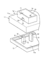
図1乃至図5に、本発明の第一実施形態に係る電気接続箱10を示す。
電気接続箱10は、自動車に配索するワイヤハーネスに接続されるヒューズボックスであり、図1に示すように、アッパケース11にロアケース12を組み付けてなる。アッパケース11およびロアケース12はいずれも樹脂成形品からなる。
図1乃至図5に、本発明の第一実施形態に係る電気接続箱10を示す。
電気接続箱10は、自動車に配索するワイヤハーネスに接続されるヒューズボックスであり、図1に示すように、アッパケース11にロアケース12を組み付けてなる。アッパケース11およびロアケース12はいずれも樹脂成形品からなる。
前記アッパケース11の上壁11aには、電源線Wの端末に接続したレバー式コネクタ100を嵌合する収容部13のフード部14を突設している。ロアケース12の底壁12aの上面には、バスバー16等の導電材を上面に固定した絶縁板18を複数積層してなる内部回路体15を固定している。該ロアケース12を前記アッパケース11に組み付け、ケース内部に前記内部回路体15を収容していると共に、バスバー16を屈曲させて形成した複数のタブ端子17をアッパケース11のフード部14内に上向きに突出させている。
前記回動レバー式コネクタ100は、図16および図17に示す回動レバー式コネクタ100と同一構成であるため、同一符合を付して説明を省略する。
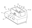
アッパケース11のフード部14には、図2に示すように、長辺側の両側壁19の中央部に下端から切り込んだ一対の切込穴20を形成している。該切込穴20の側面視形状は、長方形状の下側部と台形状の上側部とを連続させた形状よりなる
アッパケース11の上壁11aには、図2に示すように、切込穴20と連続する貫通穴22を形成し、前記コネクタ収容部13の底壁21にも、図5に示すように前記切込穴20と連通する貫通穴23を形成し、前記切込穴20を下方へ開口している。
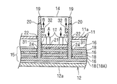
ロアケース12の底壁12aからは、図2および図3に示すように、アッパケース11の前記切込穴20に嵌めこまれる、対向した一対の軸受材31を上向きに一体に突設している。
前記軸受材31は、切込穴20の形状に対応して長方形状の板片の上側部を台形状とさせた平板よりなり、上側部の外面にカムピン32を一体に突設している。該軸受材31の肉厚T2は、前記フード部14の肉厚T1よりも大としている。
前記切込穴20の内周面20aは、図4に示すように、その全周にわたって前記軸受材31の外周面31aとの間に隙間Sがあくように形成している。
前記切込穴20の内周面20aは、図4に示すように、その全周にわたって前記軸受材31の外周面31aとの間に隙間Sがあくように形成している。
前記内部回路体15の絶縁板18には、図5に示すように、上下に連通する一対の貫通穴24を設け、該貫通穴24を前記軸受材31が貫通できるようにしている。
前記構成の電気接続箱10は、アッパケース11にロアケース12を組み付けることにより、図3および図5に示すように、各絶縁板18の貫通穴24を貫通して上向きに突出した軸受材31が、コネクタ収容部13の底壁21に設けた貫通穴23とアッパケース11の貫通穴22を連通してフード部14の切込穴20に嵌めこまれる。
電気接続箱10に回動レバー式コネクタ100を嵌合接続する際は、フード部14にコネクタ100を仮嵌合した後、軸受材31から突出した前記カムピン32に回動レバー式コネクタ100のカム溝111を係合してレバー107を回動させる。 これにより、コネクタ100を正規嵌合し、フード部14内の端子17とコネクタ100に装着された雌端子とを嵌合接続させる。
電気接続箱10に回動レバー式コネクタ100を嵌合接続する際は、フード部14にコネクタ100を仮嵌合した後、軸受材31から突出した前記カムピン32に回動レバー式コネクタ100のカム溝111を係合してレバー107を回動させる。 これにより、コネクタ100を正規嵌合し、フード部14内の端子17とコネクタ100に装着された雌端子とを嵌合接続させる。
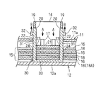
このとき、コネクタ100の強い嵌合力により、図5の矢印Aのように、端子17および該端子17を形成したバスバー16に強い押し下げ力が作用し、その強い押し下げ力はバスバー16よりも下層の絶縁板18、さらには、ロアケース12の底壁12aに伝わる。一方、前記カムピン32および該カムピン32と一体連続のロアケース12の底壁12aには、コネクタ100のレバー107の回動と同時に、図5の矢印Bに示すように上向きに引き上げる力が作用する。従って、ロアケース12の底壁12aには、矢印A方向の押し下げ力と矢印B方向の引き上げ力が同時に加わるため、両力は相殺され、引き上げも押し下げも生じず、よって、該ロアケース12の底壁12aに固定された内部回路体15のバスバー16および端子17の沈み込みを防止できる。
また、カムピン32を突設した軸受材31はロアケース12から一体に突設している。フード部14および該フード部14を設けたアッパケース11とは別体であるため、コネクタ100のレバー107の回動時にカムピン32に加わる強い引き上げ力がフード部14およびアッパケース11に直接的に作用することを防止できる。特に、図4に示すように、軸受材31の外周面31aとフード部14の切込穴20の内周面20aとの間に隙間Sを設けているため、軸受材31が多少引き上げられたとしても、フード部14およびアッパケース11の浮き上がりを防ぐ、あるいは浮き上がり量を抑えることができる。
このように、電気接続箱10は、回動レバー式コネクタ100の嵌合接続時に、フード部14およびアッパケース11の浮き上がりと、端子17の沈み込みを共に防ぐことができるため、端子17のフード部14内の突出代hの減少を有効に抑えることができ、接続安定性を高めることができる。
さらに、軸受材31の肉厚T2はフード部14の肉厚T1よりも大としているため、カムピン32にかかる大きな荷重に対する耐性および強度を備えることができ、変形や破損を防止できる。
さらに、軸受材31の肉厚T2はフード部14の肉厚T1よりも大としているため、カムピン32にかかる大きな荷重に対する耐性および強度を備えることができ、変形や破損を防止できる。
図6および図7に、第1実施形態の変形例1を示す。
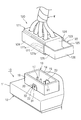
変形例1では、回動レバー式コネクタ100にかえてスライドレバー式コネクタ120を用いることができる。
変形例1では、回動レバー式コネクタ100にかえてスライドレバー式コネクタ120を用いることができる。
スライドレバー式コネクタ120は、図6および図7(A)に示すように、雌端子(図示せず)を収容したコネクタハウジング121に、該コネクタ120の嵌合方向と略直交方向にスライド移動するスライドレバー122を備えている。コネクタハウジング121は、筒状の周壁部123の長辺側の両側壁の外面に一対のカバー部124を備え、カバー部124と周壁部123との間の空間をスライドレバー122の収容空間としている。前記周壁部123の長辺側両側壁には、図7(A)に示すように、アッパケース11のフード部14に嵌めこまれた軸受材31のカムピン32を貫通させる切込穴128を設けている。
スライドレバー122は、一対のスライダー125の一端同士を操作板126で連結したコ字形状よりなり、スライダー125には、該スライダー125の先端側から操作板126側に向かって延在するカム溝127を形成している。該カム溝127は、スライダー125の先端部でコネクタ嵌合方向の先端側に開口して入口127aを形成し、該入口127aから奥端127bに向かってコネクタ離脱方向へと湾曲している。
前記構成のスライドレバー式コネクタ120は、図7(A)(B)に示すように、スライドレバー122を引き出した状態で該コネクタ120をフード部14に仮嵌合し、カムピン32をカム溝127の入口127aに嵌めこんだ後、スライドレバー122を押し込むことによりフード部14に正規嵌合される。このスライドレバー122のスライド操作は、湾曲したカム溝127とカムピン32のカム作用によってコネクタ120をフード部14内に深く嵌合させる点で、前記回動レバー式コネクタ100のレバー107の回動操作と同じである。
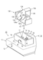
図8乃至図10に、本発明の第二実施形態を示す。
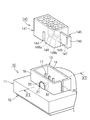
第二実施形態では、図9に示すように、一対の軸受材31を、上面にバスバー16を固定した最下層の絶縁板18Aから上向きに一体に突出させている。また、各軸受材31には、カムピン32を内側に対向させて突設している。
第二実施形態では、図9に示すように、一対の軸受材31を、上面にバスバー16を固定した最下層の絶縁板18Aから上向きに一体に突出させている。また、各軸受材31には、カムピン32を内側に対向させて突設している。
前記軸受材31を嵌めこんだアッパケース11のフード部14には、回動レバー式コネクタ130を嵌合する。該回動レバー式コネクタ130は、図8に示すように、コネクタハウジング131の内部に複数の雌端子(図示せず)を装着していると共に、該コネクタハウジング131の四角筒状の周壁部132の長辺側両側壁の外側に、該両側壁を挟むように回動レバー134を取り付けている。コネクタハウジング131の前記両側壁の外面には一対の軸部133を突設している。
前記回動レバー134は、一対の側板135の一端側を操作板136で連結した略コ字形状よりなり、前記両側板135には軸穴137を設け、該軸穴137に前記軸部133を嵌合することによって、回動レバー134をハウジング131に回動可能に軸支している。
前記回動レバー134の両側板135にはカム溝138を形成している。該カム溝138は、側板135の周縁に開口して入口138aを備えると共に、該入口138aから奥端138bに向かって前記軸穴137との距離が漸次近接するように湾曲する円弧状に延在させている。
前記回動レバー134の両側板135にはカム溝138を形成している。該カム溝138は、側板135の周縁に開口して入口138aを備えると共に、該入口138aから奥端138bに向かって前記軸穴137との距離が漸次近接するように湾曲する円弧状に延在させている。
前記構成の回動レバー式コネクタ130は、図10(A)(B)に示すように、回動レバー134の操作板136を引き上げた状態でフード部14に仮嵌合する。カムピン32をカム溝138の入口138aに嵌めこんだ後、操作板136を押し下げてレバー134を回動させることにより、フード部14に正規嵌合される。この回動レバー134の回動操作は、湾曲したカム溝138とカムピン32のカム作用によってコネクタ130をフード部14内に深く嵌合させる点で、前記回動レバー式コネクタ100の回動操作やスライドレバー式コネクタ120のスライド操作と同じである。
その他の構成は前記第1実施形態と同一構成であるため、同一符合を付して説明を省略する。
その他の構成は前記第1実施形態と同一構成であるため、同一符合を付して説明を省略する。
本第二実施形態においても、回動レバー式コネクタ130のレバー134の回動操作によりカムピン32には強い引き上げ力が作用するが、該カムピン32を設けた軸受材31はフード部14およびアッパケース11とは別体であるため、カムピン32が受けた引き上げ力がフード部14およびアッパケース11に伝わって該フード部14およびアッパケース11が浮き上がることを防止できる。
また、前記軸受材31は、フード部14内に突出させた端子17を設けたバスバー16を上面に固定した最下層の絶縁板18Aから一体に突設しており、バスバー16よりも下方に積層された絶縁板18Aで軸受材31を支持しているため、コネクタ130の嵌合時に端子17およびバスバー16に強い押し下げ力が作用しても、該バスバー16よりも下層の前記絶縁板18Aには前記軸受材31が受ける引き上げ力も作用し、押し下げ力と引き上げ力とを相殺することができる。よって、内部回路体15全体の沈み込みを防止できることにより、端子17の沈み込みも有効に防ぐことができる。
なお、本実施形態では最下層の絶縁板18Aより軸受材31を突出させているが、最上層あるいは中間層の絶縁板18より軸受材31を突出させてもよい。具体的には、回転式レバーコネクタ130と嵌合されるタブ端子17が最上層の絶縁板18から突出し、中間層および最下層の絶縁板18上からはタブ端子17が突出していない場合は、最上層の絶縁板18より軸受材31を突出させてもよい。また、中間層の絶縁板18上から回転式レバーコネクタ130と嵌合されるタブ端子17が突出し、最下層の絶縁板18Aからタブ端子17が突出していない場合には、中間層の絶縁板18から前記軸受材31を突出させてもよい。即ち、タブ端子17が突出するそれぞれの絶縁板のうち、最も下方に位置する絶縁板より軸受材31を突出させることも許容される。
図11乃至図13に本発明の第三実施形態を示す。
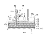
第三実施形態では、図11に示すように、フード部14の長辺側一側面に1つの切込穴20を設け、該切込穴20に1本の軸受材31を嵌めこんでいる。該軸受材31は、図12に示すように、フード部14に端子17を突出させたバスバー16を上面に固定した最下層の絶縁板18Aから上向きに一体に突設されており、該軸受材31のカムピン32は、軸受材31がフード部14の前記切込穴20に嵌めこまれたときに該フード部14内の略中央部に先端部が達するように長く突出している。
第三実施形態では、図11に示すように、フード部14の長辺側一側面に1つの切込穴20を設け、該切込穴20に1本の軸受材31を嵌めこんでいる。該軸受材31は、図12に示すように、フード部14に端子17を突出させたバスバー16を上面に固定した最下層の絶縁板18Aから上向きに一体に突設されており、該軸受材31のカムピン32は、軸受材31がフード部14の前記切込穴20に嵌めこまれたときに該フード部14内の略中央部に先端部が達するように長く突出している。
前記フード部14には、スライドレバー式コネクタ140を嵌合する。該スライドレバー式コネクタ140は、コネクタハウジング141の内部に、複数の雌端子(図示せず)を装着していると共に、図13(A)に示すように、コネクタ140の嵌合方向と略直交方向にスライドするレバー145の収容空間142を備えている。
前記コネクタハウジング141の周壁のうち、前記レバー145を挿し抜きする側の周壁には、前記レバー収容空間142と連通するレバー引き出し開口部143を形成している。また、コネクタハウジング141の周壁のうち、フード部14への嵌合状態において前記カムピン32と対向する側の周壁にはカムピン挿通溝144を形成している。このカムピン挿通溝144は、コネクタ140の嵌合方向先端側に向かって開口していると共に、前記レバー収容空間142に連通している。
前記スライドレバー145は、操作板146の中央から一枚のスライダー147を突出させたT字形状よりなり、スライダー147の一面側にはカム溝148をスライダー147の先端側から操作板146側に向かって延在させて形成している。該カム溝148は、図13(A)(B)にも示すように、スライダー147の先端部でコネクタ140の嵌合方向先端側に開口して入口148aを形成し、該入口148aから奥端148bに向かってコネクタ離脱方向へと傾斜している。
前記フード部14の一周壁には、図11に示すように、前記スライドレバー式コネクタ140のスライドレバー145を挿し抜きができるように上端から下方に切り込んだ切欠溝25を形成している。
前記構成のスライドレバー式コネクタ140は、図13(A)(B)に示すように、スライドレバー145を引き出した状態でフード部14に仮嵌合し、前記カムピン挿通溝144から導入してハウジング141内に突出させたカムピン32をカム溝148の入口148aに嵌めこんだ後、スライドレバー145を押しこむことにより、フード部14に正規嵌合される。このスライドレバー145のスライド操作は、傾斜したカム溝148とカムピン32のカム作用によってコネクタ140をフード部14内に深く嵌合させる点で、前記回動レバー式コネクタ100、130の回動操作やスライドレバー式コネクタ120のスライド操作と同じである。
その他の構成は、前記第2実施形態と同じであるため、同一符合を付して説明を省略する。
その他の構成は、前記第2実施形態と同じであるため、同一符合を付して説明を省略する。
本第三実施形態においても、フード部14およびアッパケース11の引き上げが抑制され、かつ、バスバー16を固定した最下層の絶縁板18Aに、端子17から伝播される押し下げ力と同時にカムピン32から伝播される引き上げ力が作用し、互いに相殺されることにより、絶縁板18A、ひいては端子17の沈み込みを防止することができる点は、前記第2実施形態と同じである。
図14および図15に、本発明の第四実施形態を示す。
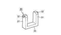
第四実施形態では、金属加工品からなる専用の軸受部材30を用いている。
前記軸受部材30は、図14に示すように、一対の軸受材31を平板状の支持部33で連結したコ字形状としている。軸受材31の形状は前記第1実施形態と同一であり、カムピン32を外側に突出させている。
全絶縁板18には、図15に示すように一対の貫通穴24を設け、各貫通穴24を上下に連通させている。
最下層の絶縁板18Aの下面側から軸受材31を貫通穴24に挿し込んで貫通させ、該軸受材31を、コネクタ収容部13の底壁21に設けた貫通穴23とアッパケース11に設けた貫通穴22も貫通させて前記フード部14の前記切込穴20に嵌めこむ。このとき、軸受部材30の支持部33は、最下層の絶縁板18Aの下面側に当接する。
第四実施形態では、金属加工品からなる専用の軸受部材30を用いている。
前記軸受部材30は、図14に示すように、一対の軸受材31を平板状の支持部33で連結したコ字形状としている。軸受材31の形状は前記第1実施形態と同一であり、カムピン32を外側に突出させている。
全絶縁板18には、図15に示すように一対の貫通穴24を設け、各貫通穴24を上下に連通させている。
最下層の絶縁板18Aの下面側から軸受材31を貫通穴24に挿し込んで貫通させ、該軸受材31を、コネクタ収容部13の底壁21に設けた貫通穴23とアッパケース11に設けた貫通穴22も貫通させて前記フード部14の前記切込穴20に嵌めこむ。このとき、軸受部材30の支持部33は、最下層の絶縁板18Aの下面側に当接する。
本実施形態においても、独立した専用の軸受部材30にカムピン32を形成しているため、コネクタ嵌合時におけるフード部14およびアッパケース11の引き上げが抑制される。また、バスバー16を固定した最下層の絶縁板18Aには、端子17から伝わる押し下げ力が作用すると同時に、カムピン32から伝わる引き上げ力が軸受部材30の前記支持部33を介して作用するため、押し下げ力が引き上げ力によって相殺され、絶縁板18、ひいては端子17の沈み込みを防止することができる。
また、軸受部材30の支持部33は、レバー式コネクタと嵌合するタブ端子17が最上層の絶縁板18のみから突出する場合には、該絶縁板18の下面に配置し、中間層の絶縁板18からタブ端子17が突出し、最下層の絶縁板からタブ端子が突出しない場合には中間層の絶縁板18の下面に配置してもよく、タブ端子17が突出するそれぞれの絶縁板のうち、最も下方に位置する絶縁板の下面に配置することも許容される。
また、軸受部材30の支持部33は、レバー式コネクタと嵌合するタブ端子17が最上層の絶縁板18のみから突出する場合には、該絶縁板18の下面に配置し、中間層の絶縁板18からタブ端子17が突出し、最下層の絶縁板からタブ端子が突出しない場合には中間層の絶縁板18の下面に配置してもよく、タブ端子17が突出するそれぞれの絶縁板のうち、最も下方に位置する絶縁板の下面に配置することも許容される。
なお、前記軸受部材30の形状は前記実施形態に限定されるものではない。フード部に嵌合するレバー式コネクタの構造に応じて、一対の軸受材の内側にカムピン32を突出させたものでも、あるいは、一枚の平板状の支持部の中央から一枚の軸受材を逆T字状に突設し該軸受材の片面からカムピンを突設してもよい。
前記軸受部材30は強度が保てるものであれば、樹脂成型品としてもよい。その場合は、レバー式コネクタの材質よりも硬度が高い樹脂を用いるのが好適である。
また、軸受部材30の一部を金属とし、該金属を樹脂でモールドしたものでも良い。その場合、金属を採用する箇所は軸受材31のみ、または支持部33のみ、あるいは軸受材31と支持部33の双方としても良く、適宜選択可能である。
このように、軸受部材30の材質は強度、寸法精度、絶縁性、コスト等を考慮して適宜に選択可能である。
また、軸受部材30の一部を金属とし、該金属を樹脂でモールドしたものでも良い。その場合、金属を採用する箇所は軸受材31のみ、または支持部33のみ、あるいは軸受材31と支持部33の双方としても良く、適宜選択可能である。
このように、軸受部材30の材質は強度、寸法精度、絶縁性、コスト等を考慮して適宜に選択可能である。
10 電気接続箱
11 アッパケース
12 ロアケース
14 フード部
16 バスバー(導電材)
17 タブ端子
18、18A 絶縁板
20 切込穴
22、23、24 貫通穴
31 軸受材
32 カムピン
100、120、130、140 レバー式コネクタ
107、122、134、145 レバー
111、127、138、148 カム溝
11 アッパケース
12 ロアケース
14 フード部
16 バスバー(導電材)
17 タブ端子
18、18A 絶縁板
20 切込穴
22、23、24 貫通穴
31 軸受材
32 カムピン
100、120、130、140 レバー式コネクタ
107、122、134、145 レバー
111、127、138、148 カム溝
Claims (4)
- アッパケースとロアケースとからなるケース内部に導電材および絶縁板を収容し、
前記アッパケースの表面にレバー式コネクタ収容部のフード部を設け、該フード部にレバー式コネクタを挿入し、レバーの回動操作またはスライド操作で該レバー式コネクタ内の端子と前記フード部の内部に下方より突出させた前記導電材の端子とを嵌合接続する電気接続箱であって、
前記フード部の対向する側壁に設けた穴と、該穴に嵌め込む軸受材を備え、
前記軸受材は前記フード部と別体の部材とし、
前記軸受材から突設した軸を前記レバー式コネクタのレバーに設けた軸穴に嵌合させることを特徴とする電気接続箱。 - 前記軸受材は、前記ロアケース、前記ケース内部に収容する絶縁板、または該ケース内に収容する専用支持材から突設している請求項1に記載の電気接続箱。
- 前記軸受材の肉厚は前記フード部の肉厚以上である請求項1または請求項2に記載の電気接続箱。
- 前記軸受材の外周面は前記フード部に設ける穴の内周面に隙間をあけて沿わせる形状としている請求項1乃至請求項3のいずれか1項に記載の電気接続箱。
Priority Applications (1)
| Application Number | Priority Date | Filing Date | Title |
|---|---|---|---|
| JP2011502569A JP5071585B2 (ja) | 2009-03-06 | 2009-09-24 | 電気接続箱 |
Applications Claiming Priority (2)
| Application Number | Priority Date | Filing Date | Title |
|---|---|---|---|
| JP2009-053199 | 2009-03-06 | ||
| JP2009053199 | 2009-03-06 |
Publications (1)
| Publication Number | Publication Date |
|---|---|
| WO2010100779A1 true WO2010100779A1 (ja) | 2010-09-10 |
Family
ID=42709354
Family Applications (1)
| Application Number | Title | Priority Date | Filing Date |
|---|---|---|---|
| PCT/JP2009/066507 Ceased WO2010100779A1 (ja) | 2009-03-06 | 2009-09-24 | 電気接続箱 |
Country Status (2)
| Country | Link |
|---|---|
| JP (1) | JP5071585B2 (ja) |
| WO (1) | WO2010100779A1 (ja) |
Cited By (1)
| Publication number | Priority date | Publication date | Assignee | Title |
|---|---|---|---|---|
| CN115244810A (zh) * | 2020-03-24 | 2022-10-25 | 住友电装株式会社 | 电气连接箱 |
Citations (3)
| Publication number | Priority date | Publication date | Assignee | Title |
|---|---|---|---|---|
| JPH10233256A (ja) * | 1997-02-17 | 1998-09-02 | Yazaki Corp | Lifコネクタ |
| JPH10243529A (ja) * | 1997-02-25 | 1998-09-11 | Yazaki Corp | 電気接続箱 |
| JP2001025134A (ja) * | 1999-07-09 | 2001-01-26 | Yazaki Corp | 電気接続箱のレバー構造 |
-
2009
- 2009-09-24 JP JP2011502569A patent/JP5071585B2/ja not_active Expired - Fee Related
- 2009-09-24 WO PCT/JP2009/066507 patent/WO2010100779A1/ja not_active Ceased
Patent Citations (3)
| Publication number | Priority date | Publication date | Assignee | Title |
|---|---|---|---|---|
| JPH10233256A (ja) * | 1997-02-17 | 1998-09-02 | Yazaki Corp | Lifコネクタ |
| JPH10243529A (ja) * | 1997-02-25 | 1998-09-11 | Yazaki Corp | 電気接続箱 |
| JP2001025134A (ja) * | 1999-07-09 | 2001-01-26 | Yazaki Corp | 電気接続箱のレバー構造 |
Cited By (1)
| Publication number | Priority date | Publication date | Assignee | Title |
|---|---|---|---|---|
| CN115244810A (zh) * | 2020-03-24 | 2022-10-25 | 住友电装株式会社 | 电气连接箱 |
Also Published As
| Publication number | Publication date |
|---|---|
| JP5071585B2 (ja) | 2012-11-14 |
| JPWO2010100779A1 (ja) | 2012-09-06 |
Similar Documents
| Publication | Publication Date | Title |
|---|---|---|
| EP2461431B1 (en) | Dual contact beam terminal | |
| US7186151B2 (en) | Electrical connector, wire harness, and method for arranging wire harness | |
| US8328579B2 (en) | Shield case and connector having the same | |
| JP4575962B2 (ja) | カードエッジコネクタ及びその組付方法 | |
| JP4074776B2 (ja) | ジャック | |
| FI126806B (en) | Coupling | |
| US11605911B2 (en) | Electrical connector including plug connector and receptacle connector detachably fitting to each other | |
| CN102610951B (zh) | 连接器 | |
| KR102076174B1 (ko) | 커넥터 | |
| JP2010198996A (ja) | 電気コネクタ | |
| CN104752896A (zh) | 电连接器 | |
| KR20030087539A (ko) | 커넥터 구조 | |
| JP5071585B2 (ja) | 電気接続箱 | |
| JP2010257863A (ja) | ロック構造及び該ロック構造を用いた電気コネクタ | |
| JP5312175B2 (ja) | コネクタ | |
| JP3152071U (ja) | 電気コネクタ | |
| JP2007179771A (ja) | コネクタ | |
| WO2010052893A1 (ja) | 電気コネクタ組立体 | |
| CN211404810U (zh) | 用于高压连接器的高压互锁机构 | |
| CN1326289C (zh) | 电连接器 | |
| JP2009170323A (ja) | コネクタ | |
| WO2020070977A1 (ja) | コネクタ組立体及びコネクタ | |
| JP2008293677A (ja) | コネクタ | |
| US11398701B2 (en) | Wafer connector and fitting connector | |
| JP3175505U (ja) | ケーブル用コネクタ |
Legal Events
| Date | Code | Title | Description |
|---|---|---|---|
| 121 | Ep: the epo has been informed by wipo that ep was designated in this application |
Ref document number: 09841139 Country of ref document: EP Kind code of ref document: A1 |
|
| ENP | Entry into the national phase |
Ref document number: 2011502569 Country of ref document: JP Kind code of ref document: A |
|
| NENP | Non-entry into the national phase |
Ref country code: DE |
|
| 122 | Ep: pct application non-entry in european phase |
Ref document number: 09841139 Country of ref document: EP Kind code of ref document: A1 |