WO2010098022A1 - 状態監視装置 - Google Patents
状態監視装置 Download PDFInfo
- Publication number
- WO2010098022A1 WO2010098022A1 PCT/JP2010/000763 JP2010000763W WO2010098022A1 WO 2010098022 A1 WO2010098022 A1 WO 2010098022A1 JP 2010000763 W JP2010000763 W JP 2010000763W WO 2010098022 A1 WO2010098022 A1 WO 2010098022A1
- Authority
- WO
- WIPO (PCT)
- Prior art keywords
- unit
- subject
- state
- monitoring device
- state monitoring
- Prior art date
- Legal status (The legal status is an assumption and is not a legal conclusion. Google has not performed a legal analysis and makes no representation as to the accuracy of the status listed.)
- Ceased
Links
Images






Classifications
-
- A—HUMAN NECESSITIES
- A61—MEDICAL OR VETERINARY SCIENCE; HYGIENE
- A61B—DIAGNOSIS; SURGERY; IDENTIFICATION
- A61B5/00—Measuring for diagnostic purposes; Identification of persons
- A61B5/103—Measuring devices for testing the shape, pattern, colour, size or movement of the body or parts thereof, for diagnostic purposes
- A61B5/11—Measuring movement of the entire body or parts thereof, e.g. head or hand tremor or mobility of a limb
- A61B5/1116—Determining posture transitions
-
- A—HUMAN NECESSITIES
- A61—MEDICAL OR VETERINARY SCIENCE; HYGIENE
- A61B—DIAGNOSIS; SURGERY; IDENTIFICATION
- A61B5/00—Measuring for diagnostic purposes; Identification of persons
- A61B5/0002—Remote monitoring of patients using telemetry, e.g. transmission of vital signals via a communication network
- A61B5/0004—Remote monitoring of patients using telemetry, e.g. transmission of vital signals via a communication network characterised by the type of physiological signal transmitted
- A61B5/0008—Temperature signals
-
- A—HUMAN NECESSITIES
- A61—MEDICAL OR VETERINARY SCIENCE; HYGIENE
- A61B—DIAGNOSIS; SURGERY; IDENTIFICATION
- A61B5/00—Measuring for diagnostic purposes; Identification of persons
- A61B5/01—Measuring temperature of body parts ; Diagnostic temperature sensing, e.g. for malignant or inflamed tissue
-
- A—HUMAN NECESSITIES
- A61—MEDICAL OR VETERINARY SCIENCE; HYGIENE
- A61B—DIAGNOSIS; SURGERY; IDENTIFICATION
- A61B5/00—Measuring for diagnostic purposes; Identification of persons
- A61B5/41—Detecting, measuring or recording for evaluating the immune or lymphatic systems
- A61B5/411—Detecting or monitoring allergy or intolerance reactions to an allergenic agent or substance
-
- A—HUMAN NECESSITIES
- A61—MEDICAL OR VETERINARY SCIENCE; HYGIENE
- A61B—DIAGNOSIS; SURGERY; IDENTIFICATION
- A61B5/00—Measuring for diagnostic purposes; Identification of persons
- A61B5/68—Arrangements of detecting, measuring or recording means, e.g. sensors, in relation to patient
- A61B5/6801—Arrangements of detecting, measuring or recording means, e.g. sensors, in relation to patient specially adapted to be attached to or worn on the body surface
- A61B5/6813—Specially adapted to be attached to a specific body part
- A61B5/6828—Leg
-
- G—PHYSICS
- G01—MEASURING; TESTING
- G01K—MEASURING TEMPERATURE; MEASURING QUANTITY OF HEAT; THERMALLY-SENSITIVE ELEMENTS NOT OTHERWISE PROVIDED FOR
- G01K1/00—Details of thermometers not specially adapted for particular types of thermometer
- G01K1/02—Means for indicating or recording specially adapted for thermometers
- G01K1/024—Means for indicating or recording specially adapted for thermometers for remote indication
-
- G—PHYSICS
- G01—MEASURING; TESTING
- G01K—MEASURING TEMPERATURE; MEASURING QUANTITY OF HEAT; THERMALLY-SENSITIVE ELEMENTS NOT OTHERWISE PROVIDED FOR
- G01K1/00—Details of thermometers not specially adapted for particular types of thermometer
- G01K1/14—Supports; Fastening devices; Arrangements for mounting thermometers in particular locations
-
- G—PHYSICS
- G01—MEASURING; TESTING
- G01K—MEASURING TEMPERATURE; MEASURING QUANTITY OF HEAT; THERMALLY-SENSITIVE ELEMENTS NOT OTHERWISE PROVIDED FOR
- G01K13/00—Thermometers specially adapted for specific purposes
- G01K13/20—Clinical contact thermometers for use with humans or animals
-
- A—HUMAN NECESSITIES
- A61—MEDICAL OR VETERINARY SCIENCE; HYGIENE
- A61B—DIAGNOSIS; SURGERY; IDENTIFICATION
- A61B2503/00—Evaluating a particular growth phase or type of persons or animals
- A61B2503/04—Babies, e.g. for SIDS detection
-
- A—HUMAN NECESSITIES
- A61—MEDICAL OR VETERINARY SCIENCE; HYGIENE
- A61B—DIAGNOSIS; SURGERY; IDENTIFICATION
- A61B5/00—Measuring for diagnostic purposes; Identification of persons
- A61B5/0002—Remote monitoring of patients using telemetry, e.g. transmission of vital signals via a communication network
- A61B5/0004—Remote monitoring of patients using telemetry, e.g. transmission of vital signals via a communication network characterised by the type of physiological signal transmitted
- A61B5/0006—ECG or EEG signals
-
- A—HUMAN NECESSITIES
- A61—MEDICAL OR VETERINARY SCIENCE; HYGIENE
- A61B—DIAGNOSIS; SURGERY; IDENTIFICATION
- A61B5/00—Measuring for diagnostic purposes; Identification of persons
- A61B5/02—Detecting, measuring or recording for evaluating the cardiovascular system, e.g. pulse, heart rate, blood pressure or blood flow
- A61B5/024—Measuring pulse rate or heart rate
- A61B5/02416—Measuring pulse rate or heart rate using photoplethysmograph signals, e.g. generated by infrared radiation
-
- A—HUMAN NECESSITIES
- A61—MEDICAL OR VETERINARY SCIENCE; HYGIENE
- A61B—DIAGNOSIS; SURGERY; IDENTIFICATION
- A61B5/00—Measuring for diagnostic purposes; Identification of persons
- A61B5/145—Measuring characteristics of blood in vivo, e.g. gas concentration or pH-value ; Measuring characteristics of body fluids or tissues, e.g. interstitial fluid or cerebral tissue
- A61B5/1455—Measuring characteristics of blood in vivo, e.g. gas concentration or pH-value ; Measuring characteristics of body fluids or tissues, e.g. interstitial fluid or cerebral tissue using optical sensors, e.g. spectral photometrical oximeters
-
- A—HUMAN NECESSITIES
- A61—MEDICAL OR VETERINARY SCIENCE; HYGIENE
- A61B—DIAGNOSIS; SURGERY; IDENTIFICATION
- A61B5/00—Measuring for diagnostic purposes; Identification of persons
- A61B5/68—Arrangements of detecting, measuring or recording means, e.g. sensors, in relation to patient
- A61B5/6801—Arrangements of detecting, measuring or recording means, e.g. sensors, in relation to patient specially adapted to be attached to or worn on the body surface
- A61B5/6813—Specially adapted to be attached to a specific body part
- A61B5/6824—Arm or wrist
-
- A—HUMAN NECESSITIES
- A61—MEDICAL OR VETERINARY SCIENCE; HYGIENE
- A61B—DIAGNOSIS; SURGERY; IDENTIFICATION
- A61B5/00—Measuring for diagnostic purposes; Identification of persons
- A61B5/68—Arrangements of detecting, measuring or recording means, e.g. sensors, in relation to patient
- A61B5/6801—Arrangements of detecting, measuring or recording means, e.g. sensors, in relation to patient specially adapted to be attached to or worn on the body surface
- A61B5/683—Means for maintaining contact with the body
- A61B5/6831—Straps, bands or harnesses
Definitions
- the present invention relates to a state monitoring device that monitors the state of subjects such as infants, the elderly, and bedridden patients.
- Japanese Patent Application Laid-Open No. 2004-181218 Japanese Patent No. 3661686, and Japanese Patent Application Laid-Open No. 2007-229076 have been proposed as state monitoring devices for monitoring the condition of subjects such as infants, the elderly, and bedridden patients. Has been.
- a wearing body on which a sensor is arranged is attached to a subject, the state of the subject is always detected, and data detected by the sensor is transmitted wirelessly or the like.
- the condition of the subject is monitored by transmitting to an external device.
- the antenna unit and the IC tag are integrally configured, and in order to perform the body temperature measurement of the subject, every time the body temperature is measured, The user needs to bring the reader device close to the vicinity of the wearing body. For this reason, there exists a problem that it is unsuitable for the application to the apparatus which always monitors the state of a subject.
- the present invention has been made in view of the above problems, and in a state monitoring device that monitors the state of a subject, the present invention is attached to the subject while maintaining measurement accuracy when measuring the state of the subject.
- the purpose is to reduce the weight and cost of the mounted body.
- a state monitoring apparatus has the following configuration. That is, A state monitoring device comprising a mounting body to be mounted on a subject and a main body unit communicating with the mounting body, and monitoring the state of the subject,
- the wearing body is A contact surface that contacts the measurement site of the subject; A winding portion for maintaining a state in which the contact surface is in contact with the measurement site, and has two gripping curved surfaces for gripping an outer peripheral surface of the site including the measurement site of the subject; A winding part capable of expanding the diameter according to the diameter of the part by elastically deforming the curved surface in the radial direction;
- a processing unit that is arranged on the contact surface and outputs data corresponding to the body temperature of the measurement site of the subject when activated, An antenna unit that is disposed in the winding unit and generates an induced electromotive force to start the processing unit and transmits data output from the processing unit to the main body unit;
- the main body is A communication unit that generates an induced electromotive force in the antenna unit by
- the weight of the mounting body to be attached to the subject and the low cost are maintained while maintaining the measurement accuracy when measuring the state of the subject. Can be realized.
- FIG. 2 is a diagram illustrating a circuit configuration of a sensor unit 211 of a state measurement unit 200.
- FIG. 2 is a diagram illustrating a circuit configuration of a circuit unit 212 of a state measurement unit 200.
- FIG. FIG. 6 is a diagram for explaining the content of body temperature data calculation processing in a signal processing unit 304 of the main body 300.
- It is a figure which shows the function structure of the state measurement part 900 of the mounting body.
- It is a figure which shows the function structure of the state measurement part 1000 of the mounting body.
- It is a figure which shows the function structure of the state measurement part 1100 of the mounting body.
- FIG. It is a figure which shows the external appearance of the mounting body 1300.
- FIG. It is a figure which shows the external appearance of the mounting body 1300.
- FIG. is a figure which shows
- the state monitoring apparatus includes a mounting body 100 and a main body unit 300. As shown in FIG. 1A, the mounting body 100 is mounted on, for example, an infant P lying on the bed or lying on the bed with a diaper Q, and the main body 300 is fixed at a position away from the infant P by a predetermined distance.
- the mounting body 100 is mounted on, for example, an infant P lying on the bed or lying on the bed with a diaper Q, and the main body 300 is fixed at a position away from the infant P by a predetermined distance.
- FIG. 1B is a diagram showing an external configuration of the mounting body 100.
- the mounting body 100 includes a curler 230 mounted on a body temperature measurement site of the infant P, a processing unit 210 having a semiconductor temperature sensor, and an antenna unit 220.
- Part 200 (RFID) RFID
- the curler 230 is further provided with a contact portion 231 that contacts the thigh that is a body temperature measurement site of the infant P with the processing unit 210, and a contact portion that contacts the thigh that is the body temperature measurement site of the infant with the antenna unit 220. And a winding portion 232 for maintaining the state in which 231 is brought into contact.
- the winding portion 232 is substantially rigid and is obtained by blending a softening agent such as SEBS with polyethylene, polypropylene, cyclic polyolefin, polycarbonate, polyethylene terephthalate, polybutylene terephthalate, polymethylpentene 1, or a mixture thereof. It is comprised by the material etc. which were made.
- a softening agent such as SEBS with polyethylene, polypropylene, cyclic polyolefin, polycarbonate, polyethylene terephthalate, polybutylene terephthalate, polymethylpentene 1, or a mixture thereof. It is comprised by the material etc. which were made.
- the winding portion 232 includes two gripping curved surfaces that grip the outer peripheral surface of the thigh, which is a body temperature measurement site, and the two gripping curved surfaces are substantially C-shaped. Further, the diameter can be increased by elastically deforming in the radial direction. With this configuration, it is possible to maintain a state in which the contact portion 231 is in contact with the thigh which is a body temperature measurement site. At this time, the bending stress of the winding part 232 is preferably 30 to 130 MPa.
- the raw material of the winding part 232 will not be limited to the said raw material, if it is a flexible material which can be expanded in diameter, For example, metals, such as ceramics and stainless steel, may be sufficient.
- the two gripping curved surfaces of the winding part 232 further have slits along the circumferential direction of the outer peripheral surface of the thigh, which is a body temperature measurement site. Further, the gripping curved surfaces adjacent via the slits have different outer diameters. By adopting such a shape, it is possible to improve the wearability with respect to a tapered portion such as the upper arm or the thigh.
- the number of slits and the outer diameter of the winding part 232 are not limited to the above example.
- the processing unit 210 having a semiconductor temperature sensor is provided inside the contact unit 231, and the antenna unit 220 is provided inside the winding unit 232.
- the antenna unit 220 is not necessarily provided inside the winding unit 232, and may be provided outside the winding unit 232.
- the contact part 231 has a convex shape in the inner direction in order to improve the contact between the processing part 210 and the body temperature measurement site.
- the main unit 300 includes a display unit that displays body temperature, a notification unit such as a buzzer, a reading unit that reads data from a processing unit wirelessly, an input unit that inputs various information, a storage unit, and a control unit such as a microcomputer. (CPU), an external communication unit that communicates with an information communication network such as the Internet using i-mode or the like (details will be described later).
- a display unit that displays body temperature
- a notification unit such as a buzzer
- a reading unit that reads data from a processing unit wirelessly
- an input unit that inputs various information
- a storage unit such as a microcomputer. (CPU)
- a control unit such as a microcomputer. (CPU)
- an external communication unit that communicates with an information communication network such as the Internet using i-mode or the like (details will be described later).
- control unit of the main unit 300 includes a ROM that stores a control program executed by the control unit and controls the entire main unit 300, various data, and the like, and a RAM that temporarily stores various data as a work area.
- the main body 300 for example, information on vaccination (immunization of influenza, mumps, polio, pertussis, rubella, measles, tuberculosis, etc.) and past medication data (drug name, dose, Information such as the administration date and time: Necessary for carrying out medication avoiding allergic reactions) can be input via the input unit, and can be stored and displayed.
- vaccination immuno of influenza, mumps, polio, pertussis, rubella, measles, tuberculosis, etc.
- past medication data drug name, dose, Information such as the administration date and time: Necessary for carrying out medication avoiding allergic reactions
- body temperature body weight (necessary for determining the dose)
- blood pressure pulse, blood glucose level, etc.
- the main body 300 can also serve as a maternal and child health notebook.
- the main body unit 300 needs to communicate with a plurality of state measuring units at the same time. For this reason, it is preferable that the state measuring unit is formed in an anti-colonic type.
- a server data processing apparatus
- the main body unit 300 may be connected, and a management site / medical site may be formed on the server.
- a management site / medical site may be formed on the server.
- it may be configured to be associated with the ID of the infant P so that biological information such as pulse, respiration, blood pressure, body temperature, blood oxygen saturation, blood glucose and the like can be collected, tabulated and analyzed in real time.
- biological information such as pulse, respiration, blood pressure, body temperature, blood oxygen saturation, blood glucose and the like can be collected, tabulated and analyzed in real time.
- a management PC is installed on the desk of the doctor in charge, so that the doctor in charge can grasp and monitor the physical condition of the subject (for example, the infant P) at any time, receive an abnormality report of the subject, An instruction may be given to the nurse's waiting room as appropriate, or the nurse may be contacted by a handy nurse call.
- FIG. 2 is a diagram illustrating a functional configuration of a state measurement unit 200 (RFID) including an antenna unit 220 and a processing unit 210.
- RFID state measurement unit 200
- 202 is a wireless interface unit, which includes a rectifier circuit, a booster circuit, and the like.
- the AC voltage generated in the antenna unit 220 is converted into a predetermined DC voltage and supplied to the storage unit 203 and a control unit (CPU) 205 such as a microcomputer.
- the control unit 205 includes a ROM that is executed by the control unit 205 and stores a control program for controlling the entire state measurement unit 200 and various data, and a RAM that temporarily stores various data as a work area.
- voltage data (data corresponding to the body temperature of the subject) acquired in the control unit 205 is transmitted to the main body unit 300 through the antenna unit 220 in a predetermined format together with various data.
- the storage unit 203 stores calibration data of a temperature sensing unit 204 described later, identification information unique to the processing unit 210, and the like.
- the storage unit 203 includes an EEPROM and is configured to store voltage data acquired by the control unit 205. In this way, by providing the state measurement unit 200 itself with a storage function, even when the infant P is transferred to another bed or another room, the voltage data is read using the main body unit 300. It becomes possible to display the past body temperature measurement result of the infant P.
- the voltage data stored in the storage unit 203 may be an anti-coregion type so that the main body unit 300 does not acquire information on the wrong infant P ′ (not shown). Further, the security function may be enhanced by encrypting the signal output from the antenna unit 220.
- the temperature sensing unit 204 includes a sensor unit 211 including a semiconductor temperature sensor and a circuit unit 212 that processes the output of the sensor unit 211.
- a C-MOS temperature sensor or the like is used as the semiconductor temperature sensor.
- the semiconductor temperature sensor has a characteristic of outputting an analog signal almost linearly with respect to a temperature change, and can be miniaturized and integrated with the processing unit 210. Further, a temperature resolution of 0.01 ° C. can be realized between 35 and 42 ° C. Details of the circuit configurations of the sensor unit 211 and the circuit unit 212 will be described later.
- the processing unit 210 has a width W ⁇ length L of 5 mm ⁇ 5 mm and a thickness T of about 1.5 mm.
- the processing unit 210 may be an electromagnetic wave of any frequency as long as communication (transmission / reception) using an electromagnetic wave having a frequency that can pass through the living body is possible, but in this embodiment, for example, 13.56 MHz. Electromagnetic waves shall be used.
- the diameter of the antenna portion is not limited to a specific shape, but preferably has a circular shape, a square shape, a rectangular shape, or the like.
- the diameter D is preferably 20 mm to 40 mm
- the thickness T is preferably about 1 mm.
- the length of the long side is L1
- the state measuring unit 200 is configured so that the curler 230 can be used when the curler 230 is to be replaced, when it is desired to remove dirt from the curler 230 with moisture, or when the processing unit or the antenna unit is to be replaced with another curler. It shall be comprised so that attachment or detachment is possible.
- FIG. 3 is a diagram illustrating a functional configuration of the main body unit 300.
- reference numeral 310 denotes a reading unit, which includes an antenna unit 301, a wireless interface unit 302, a signal conversion unit 303, and a signal processing unit 304.
- the antenna unit 301 generates an induced electromotive force by being magnetically coupled to the antenna unit 220 of the state measurement unit 200, and supplies power to the processing unit 210 or receives data from the processing unit 210.
- the wireless interface unit 302 controls the voltage applied to the antenna unit 301 or supplies data received from the processing unit 210 via the antenna unit 301 in order to supply power to the processing unit 210 via the antenna unit 301. Or transmitted to the conversion unit 303.
- the signal conversion unit 303 converts the data transmitted from the wireless interface unit 302 into digital data and transmits it to the signal processing unit 304.
- the signal processing unit 304 processes the digital data received from the signal conversion unit 303 and calculates body temperature data. Specifically, body temperature data is calculated based on voltage data and calibration data included in the received digital data. The calculated body temperature data is transmitted to the control unit 311 together with the identification information included in the received digital data.
- the control unit 311 controls operations of the wireless interface unit 302, the signal conversion unit 303, and the signal processing unit 304.
- the body temperature data transmitted from the signal processing unit 304 is stored in the storage unit 312 together with the identification information or displayed on the display unit 313. Further, the body temperature data stored in the storage unit 312 is transmitted to the other information processing apparatus (another information processing apparatus wired by way of the external communication unit 314) via the external communication unit 314 together with the identification information.
- the other information processing apparatus another information processing apparatus wired by way of the external communication unit 314
- the input unit 315 settings for body temperature measurement are input and conditions are selected.
- the notifying unit 316 notifies the user that the body temperature data is abnormal or that the measurement is completed by a buzzer, a vibrator, light, or the like.
- measurement start time setting (time setting) is instructed by the input unit 315 or the like. Thereby, the state monitoring function is started.
- a time condition set and input in advance via the input unit 315 for example, when a measurement start instruction is input after the mounting body 100 is mounted on the infant P or when a predetermined temperature rise can be confirmed.
- an electromagnetic wave having a predetermined frequency for example, 13.56 MHz
- various data including the output of the semiconductor temperature sensor obtained in synchronization with the signal is read from the state measuring unit 200.
- body temperature data calculated based on the read various data is stored in the storage unit 312.
- the stored body temperature data is compared with a threshold value.
- the upper limit value is set to 37.5 ° C. and the lower limit value is set to 35.5 ° C. It is assumed that the upper limit value / lower limit value can be arbitrarily set and input by the user based on body temperature trend information for a predetermined period.
- the notifying means 316 When it is determined that the body temperature data is abnormal as a result of the comparison with the threshold value, the notifying means 316 generates an alarm. Further, when the body temperature measurement is completed, the notification means 316 such as a buzzer, a vibrator, and light operates to notify the user.
- “fever” is displayed on the display unit 313.
- the information to that effect is stored in the storage unit 312 in association with the body temperature data. If it is determined that there is an abnormality, the body temperature may be measured again.
- the body temperature data measured by the storage unit 312 is stored, and the display unit 313 displays the body temperature data. Body temperature data is displayed together with the measurement date.
- the pulse, blood oxygen saturation (SPO2), and the like measured by a pulse oximeter connected to the main body unit 300 via the external communication unit 314 are acquired. You may do it.
- medication data may be input via the input unit 315.
- the acquired pulse, blood oxygen saturation, and inputted medication data may be stored in association with body temperature data. Thereby, when displaying the trend graph of body temperature data, it becomes possible to display the acquired pulse, blood oxygen saturation, and inputted medication data in an overlapping manner, such as influenza, RS (Respiratory Syncytial) virus, etc. This is because it becomes possible to easily grasp a respiratory disease due to an infection or the like.
- FIG. 4 is a diagram illustrating a flow of a body temperature measurement process in the state monitoring device.
- the antenna unit 301 of the main body unit 300 when the antenna unit 301 of the main body unit 300 is excited at a predetermined time interval after the main body unit 300 is activated, the antenna unit 301 and the antenna are generated by electromagnetic waves having a predetermined frequency, for example, 13.56 MHz.
- the unit 220 is magnetically coupled, and power is supplied from the main body unit 300 to the state measuring unit 200 of the mounting unit (step S401).
- the processing unit 210 is activated, and it is determined whether or not the state measurement unit 200 is in a state that affects the accuracy of body temperature measurement (step S411).
- the “state in which the state measurement unit 200 affects the accuracy of body temperature measurement” means that the voltage of a certain value or more is excited and the processing unit 210 and the antenna unit 220 generate heat, thereby affecting the accuracy of body temperature measurement. A state with a high possibility.
- the processing unit 210 When it is determined that the state measurement unit 200 is in a state that affects the accuracy of body temperature measurement, the processing unit 210 does not perform the subsequent processing. In this case, the main body unit 300 determines that there is no data transmission from the state measurement unit 200 within a certain time after the power is supplied, and displays an error on the display unit 313 (step S421). At this time, not only an error display but also an alarm or the like by the notification means 316 may be performed.
- the processing unit 210 starts processing. Specifically, after switching to a predetermined determination range (details will be described later), a current is passed through the semiconductor temperature sensor in the sensor unit 211 to detect a band gap voltage (details will be described later) (steps S413 and S414). ).
- the circuit unit 212 processes the detected band gap voltage, and the control unit 205 acquires voltage data (step S415).
- the acquired voltage data is transmitted to the main body 300 together with the calibration data and identification information stored in the storage unit 203 (steps S416 and S402).
- the body unit 300 calculates body temperature data based on the voltage data and calibration data transmitted from the state measurement unit 200. Further, the calculated body temperature data is stored in the storage unit 312 in association with the identification information and displayed on the display unit 313 (step S421).
- FIG. 5 is a diagram illustrating characteristics of the semiconductor temperature sensor.
- the semiconductor temperature sensor included in the sensor unit 211 of the present embodiment is configured by coupling a P-type semiconductor and an N-type semiconductor, and a voltage (band gap) generated at a coupling unit (junction) when a direct current is passed.
- the voltage Vb) is detected (5A in FIG. 5).
- the band gap voltage Vb and the temperature have linearity in a wide range of approximately ⁇ 40 ° C. to + 150 ° C. Therefore, the temperature can be calculated based on the detected band gap voltage Vb.
- Such a semiconductor temperature sensor has an advantage that it is more resistant to changes with time and less susceptible to noise than a thermistor.
- FIG. 6 is a diagram illustrating a circuit configuration of the sensor unit 211 configured using the semiconductor temperature sensor illustrated in 5A of FIG.
- reference numeral 601 denotes a constant current circuit, which adjusts the current flowing through each semiconductor temperature sensor to be uniform based on the voltage Vcc supplied from the control unit 205.
- 602 is a semiconductor temperature sensor, and is connected in series to the constant current circuit 601 on the downstream side of the constant current circuit 601.
- a plurality of semiconductor temperature sensors 602 are connected to the constant current circuit 601, and the respective semiconductor temperature sensors are connected in parallel to each other.
- the reason why the plurality of semiconductor temperature sensors are connected in parallel is to eliminate the influence of individual differences of the semiconductor temperature sensors.
- the influence of individual differences of semiconductor temperature sensors cannot be ignored.
- the sensor unit 211 a plurality of semiconductor temperature sensors are connected in parallel to obtain an average value. , Trying to eliminate the effects of individual differences. Therefore, the sensor unit 211 outputs the average value Vb_avg of the voltages Vb1, Vb2,... Vbn output from each semiconductor temperature sensor.
- each semiconductor temperature sensor is not limited to once, and may be configured to flow multiple times.
- the average value Vb_avg is output from the sensor unit 211 a plurality of times.
- FIG. 7 is a diagram illustrating a circuit configuration of the circuit unit 212.
- the circuit unit 212 includes a system connected to the A / D converter 701 via the comparison / amplifier 711 and the analog switch 712, and an A / D via the comparison / amplifier 721 and the analog switch 722. It is composed of two systems connected to the D converter 701.
- the voltage Vb_avg output from the sensor unit 211 is output to the A / D converter 701 in the measurement range of ⁇ 40 ° C. to + 150 ° C.
- the voltage Vb_avg output from the sensor unit 211 is output to the A / D converter 701 in a measurement range of 20 ° C. to 50 ° C.
- Whether to output using the first system or the second system (that is, the measurement range) is controlled by switching the analog switches 712 and 722 based on the signal from the control circuit 702. The When more accurate body temperature measurement is performed, the second system is selected.
- the voltage Vb_avg input to the A / D converter 701 is A / D converted by the A / D converter 701 and input to the control circuit 702 as digital data.
- the digital data input to the control circuit 702 is transmitted to the wireless interface unit 202.
- each digital data is temporarily stored in the memory 703, and all the digital data stored in the memory 703 is stored in the control circuit 702. After the average value is calculated, it is transmitted to the wireless interface unit 202.
- FIG. 8 is a diagram for explaining the contents of processing for calculating body temperature data in the signal processing unit 304.
- the received voltage data is substituted. Derived body temperature data.
- 8A in FIG. 8 is a diagram showing a correction process when one type of calibration data corresponding to one type of temperature is received.
- the offset value of the correspondence function between the voltage data and the body temperature data in the semiconductor temperature sensor serving as a reference is adjusted. To do. Specifically, the graph 801 is translated in the direction of the arrow as a whole to obtain a graph 802.
- the signal processing unit 304 derives body temperature data by substituting the voltage data received from the state measurement unit 200 into the graph 802 after the parallel movement.
- 8B in FIG. 8 is a diagram showing correction processing when two types of calibration data corresponding to two types of temperatures are received. As shown in 8B of FIG. 8, when two types of calibration data corresponding to two types of temperatures are received, a straight line 803 passing through the two points is calculated, and the voltage data and body temperature data in the semiconductor temperature sensor are calculated. Is a graph showing the correspondence relationship with.
- the temperature data is derived by substituting the voltage data received from the state measurement unit 200 into the calculated straight line 803.
- 8C in FIG. 8 is a diagram showing a correction process when three or more types of calibration data corresponding to three or more types of temperatures are received. As shown in 8C of FIG. 8, when three or more kinds of calibration data corresponding to three or more kinds of temperatures are received, a regression line 804 is calculated by the least square method based on the three or more points. This is a graph showing the correspondence between voltage data and body temperature data in the semiconductor temperature sensor.
- the signal processing unit 304 calculates body temperature data by substituting the voltage data received from the state measurement unit 200 into the calculated regression line 804.
- the mounting body is a curler type
- the antenna unit is disposed on the winding portion
- the processing unit having the semiconductor temperature sensor is disposed on the contact portion. It was.
- the semiconductor temperature sensor In order to eliminate the influence of individual differences of the semiconductor temperature sensors, a plurality of semiconductor temperature sensors are connected in parallel in the sensor unit. -In order to eliminate measurement errors, a current was passed through the sensor section a plurality of times and an average value was output during one body temperature measurement. -Configuration to store calibration data for each processing unit in the storage unit in the processing unit to eliminate the influence of individual differences in the processing unit, and transmit calibration data together when transmitting voltage data to the main unit It was. As a result, it became possible to realize a more accurate body temperature measurement.
- FIG. 9 is a diagram illustrating a functional configuration of the state measurement unit 900 in the present embodiment.
- reference numeral 906 denotes body movement detecting means for measuring body movement / position information of the subject.
- the body motion detection unit 906 for example, a MEMS type triaxial acceleration sensor is used.
- the MEMS type triaxial acceleration sensor can be roughly classified into three types, ie, a piezoresistive type, a capacitance type, and a thermal detection type, depending on the detection mechanism.
- the state measurement unit 900 in this embodiment may use any of the detection mechanisms.
- the body motion detection means 906 is not limited to the MEMS type triaxial acceleration sensor, and for example, an inclination sensor or a gyroscope respectively arranged in the triaxial direction may be used.
- the body movement detecting means 906 is activated when the state measuring section 900 is excited from the main body section 300 at a predetermined time interval, and detects body movement / position information.
- the detected body movement / position information is transmitted to the main body 300 together with voltage data detected by the activation of the semiconductor temperature sensor (the detected body movement / position information is generated by the activation of the semiconductor temperature sensor). In association with the detected voltage data, it is stored in the EEPROM of the storage unit 203).
- the display unit 313 of the main unit 300 receives and displays various data transmitted from the state measurement unit 900. Thereby, the user can check not only body temperature data but also body movement / position information due to turning over or coughing that could not be confirmed only by body temperature data.
- the present invention is not limited to this, and may be configured to detect, for example, the state of sweating of the subject. .
- details of the present embodiment will be described focusing on differences from the first embodiment.
- FIG. 10 is a diagram illustrating a functional configuration of the state measurement unit 1000 according to the present embodiment.
- reference numeral 1006 denotes a humidity sensor, which measures a subject's sweating state.
- the humidity sensor 1006 for example, a MEMS type humidity sensor (polymer film humidity sensor, ceramic humidity sensor, or the like) is used.
- the polymer film humidity sensor is a capacitance-type sensor that utilizes the property that the capacitance of the wet and dry material changes according to the amount of moisture adsorbed by the wet and dry material of the cellulosic hydrophilic polymer.
- the ceramic humidity sensor is preferably a MgCr 2 O 4 —TiO 2 ceramics or TiO 2 —V 2 O 5 ceramics humidity sensor.
- the humidity sensor 1006 is activated when the state measuring unit 1000 is excited by the main body unit 300 at a predetermined time interval, and detects a sweating state.
- the detected sweating state is transmitted to the main body unit 300 together with voltage data detected by the activation of the semiconductor temperature sensor (the detected sweating state is the voltage data detected by the activation of the semiconductor temperature sensor and the voltage data detected by the activation of the semiconductor temperature sensor).
- the detected sweating state is the voltage data detected by the activation of the semiconductor temperature sensor and the voltage data detected by the activation of the semiconductor temperature sensor.
- it is stored in the EEPROM of the storage unit 203).
- the display unit 313 of the main unit 300 receives and displays various data transmitted from the state measurement unit 900. Accordingly, the user can check sweating (a sign of recovery) or sweating due to poor physical condition, which cannot be confirmed not only from the body temperature data but also from the body temperature data alone.
- the main body unit 300 is configured to be able to display a combination of body temperature data and body movement / position information or a combination of body temperature data and sweating information. It is not limited. For example, it is good also as a structure which can be displayed about the combination of body temperature data, body movement and body position information, and sweating information.
- a combination of body temperature data and body movement / position information or a combination of body temperature data and sweating information It is not limited. For example, it is good also as a structure which can be displayed about the combination of body temperature data, body movement and body position information, and sweating information.
- FIG. 11 is a diagram illustrating a functional configuration of the state measurement unit 1100 according to the present embodiment.
- reference numeral 906 denotes body movement detecting means for measuring body movement / position information of the subject.
- the body motion detection unit 906 for example, a MEMS type triaxial acceleration sensor is used.
- the MEMS type triaxial acceleration sensor can be roughly classified into three types, ie, a piezoresistive type, a capacitance type, and a thermal detection type, depending on the detection mechanism. In the present embodiment, any of the detection mechanisms may be used.
- the body motion detection means 906 is not limited to the MEMS type triaxial acceleration sensor, and for example, an inclination sensor or a gyroscope respectively arranged in the triaxial direction may be used.
- reference numeral 1006 denotes a humidity sensor, which measures a subject's sweating state.
- a humidity sensor 1006 for example, a MEMS type humidity sensor (polymer film humidity sensor, ceramic humidity sensor, or the like) is used.
- the polymer film humidity sensor is a capacitance type sensor that utilizes the property that the capacitance of the wet and dry material changes according to the amount of moisture adsorbed by the dry and wet material made of cellulosic hydrophilic polymer.
- the sensor is preferably a sensor, and the ceramic humidity sensor is preferably a MgCr 2 O 4 —TiO 2 ceramic or TiO 2 —V 2 O 5 ceramic humidity sensor.
- the body movement detecting means 906 and the humidity sensor 1006 are activated when the state measuring section 1100 is excited by the main body section 300 at predetermined time intervals, and detect body movement / position information and sweating state of the subject, respectively.
- the detected body movement / position information and sweating state are transmitted to the main body 300 together with voltage data detected by the activation of the semiconductor temperature sensor (the detected body movement / position information and sweating state are
- the data is stored in the EEPROM of the storage unit 203 in association with the voltage data detected by the activation of the semiconductor temperature sensor).
- the display unit 313 of the main body unit 300 receives and displays various data transmitted from the state measurement unit 1100.
- the user can check not only body temperature data but also body movement / position information due to turning over or coughing that could not be confirmed only by body temperature data.
- body movement / position information due to turning over or coughing that could not be confirmed only by body temperature data.
- sweating a sign of recovery
- the surface property of the winding portion 232 of the curler 230 is not particularly mentioned. However, since the winding portion 232 comes into contact with the skin of the subject, for example, silk, cotton, hemp, A material that can be a material for clothing such as fibers such as nylon and polyester, artificial leather, and nonwoven fabric is preferable.
- the curler 230 is attached to the body temperature measurement site of the subject using the flexibility of the material of the winding portion 232 of the curler 230. It is not limited to this.
- a male surface fastener 1230 and a female surface fastener 1240 are provided at the front end of one inner surface of the winding portion 232, and a female surface fastener 1240 at the front end of the other outer surface.
- the curler 230 may be attached to the body temperature measurement site of the subject.
- the male surface fastener 1230 and the female surface fastener 1240 function as a one-touch type locking member. Note that the male surface fastener 1230 and the female surface fastener 1240 are provided at the distal end corresponding to a range corresponding to the diameter of the measurement site of the subject.
- the winding portion 232 has a slit, and the gripping curved surfaces adjacent to each other through the slit have different outer diameters.
- the present invention is not limited to this. Instead, for example, as shown in FIG. 12, the curvature of the gripped curved surface may gradually change in the longitudinal direction (from the front side to the back side).
- the mounting body 1200 has a fan shape when viewed from the upper surface (above the contact portion 231).
- the configuration is such that the flexibility of the material of the winding portion 232 of the curler 230 is used to attach to the body temperature measurement site of the subject.
- the present invention is not limited to this.
- a belt 1340 with a buckle 1350 may be attached to the outer surface of the curler 230 (FIG. 13). By attaching the belt 1340 with the buckle 1350, the length of the belt can be adjusted, and the difference in the diameter of the body temperature measurement site of the subject can be dealt with.
- the buckle 1350 functions as a one-touch type locking member (FIG. 14).
- the buckle 250 is a one-touch type, and any shape and material may be used as long as it secures locking.
- the buckle 250 is preferably a rigid body, for example, plastic such as polyethylene, polypropylene, and cyclic polyolefin. It is preferable to use metal, metals such as ceramics and stainless steel.
- the main body unit 300 includes the antenna unit 301, the wireless interface unit 302, the signal conversion unit 303, the signal processing unit 304, the control unit 311, the storage unit 312, the display unit 313, the external communication unit 314, and the input.
- the unit 315 is provided, the functional configuration of the main body unit 300 is not limited to this.
- an external device may be communicably connected via the external communication unit 314, and the external device may have user interface functions such as the display unit 313 and the input unit 315.
- the main body unit 300 functions as a relay device that transmits the result of the state measurement process to the external device.
- the main body 300 fixed at a predetermined distance from the infant P can be reduced in size, while the state measurement processing by the main body 300 is operated and monitored from a remotely located external device. It becomes possible.
Landscapes
- Health & Medical Sciences (AREA)
- Life Sciences & Earth Sciences (AREA)
- Physics & Mathematics (AREA)
- Engineering & Computer Science (AREA)
- Surgery (AREA)
- Public Health (AREA)
- Biomedical Technology (AREA)
- Heart & Thoracic Surgery (AREA)
- Medical Informatics (AREA)
- Molecular Biology (AREA)
- Biophysics (AREA)
- Animal Behavior & Ethology (AREA)
- General Health & Medical Sciences (AREA)
- Pathology (AREA)
- Veterinary Medicine (AREA)
- General Physics & Mathematics (AREA)
- Physiology (AREA)
- Dentistry (AREA)
- Oral & Maxillofacial Surgery (AREA)
- Computer Networks & Wireless Communication (AREA)
- Immunology (AREA)
- Vascular Medicine (AREA)
- Measuring And Recording Apparatus For Diagnosis (AREA)
Abstract
被検者の状態監視を行う状態監視装置において、被検者の状態を測定する際の測定精度を維持しつつ、被検者に装着する装着体の軽量化、低コスト化を実現する。本発明に係る状態監視装置は、被検者に装着される装着体と、該装着体と通信する本体部とを備え、前記装着体は、測定部位に接触する接触面と、測定部位の外周面を把持する2つの把持曲面を有する巻き付け部と、前記接触面に配された半導体温度センサを有する処理部と、前記巻き付け部に配されたアンテナ部と、を備え、前記本体部は、所定の時間間隔で電磁波を出力しアンテナ部に誘導起電力を発生させるとともに、半導体温度センサの出力を受信する通信部と、前記通信部における通信結果に基づいて算出された被検者の体温データを表示する表示部とを備える。
Description
本発明は、乳幼児やお年寄り、寝たきり患者等の被検者の状態監視を行う状態監視装置に関するものである。
従来より、乳幼児やお年寄り、寝たきり患者等の被検者の状態監視を行う状態監視装置として、例えば、特開平2004-181218号公報、特許第3661686号、特開2007-229076号公報等が提案されている。
これらの文献に開示された状態監視装置では、センサが配された装着体を被検者に装着し、被検者の状態を常時検知するとともに、センサにより検知されたデータを無線等を介して外部機器に送信することで、被検者の状態を監視している。このような構成の場合、センサを動作させ、かつ検知したデータを送信するための電源をセンサとともに被検者側に装着しておく必要がある。このため、被検者にとっては装着体の重量が重くなるとともに、コストが高くなるという問題がある。
一方で、近年、RFID等を用いてデータの送受信を行う近距離無線通信技術が汎用化されており、例えば、特開2003-270051号公報では、被検者に装着された半導体センサにリーダ装置を近づけることで、当該半導体センサを起動させ、体温測定を実行させるとともに、測定結果を読み取る構成が提案されている。当該文献によれば、被検者に装着される装着体を軽量化できるとともに、低コスト化を実現することができる。
しかしながら、特開2003-270051号公報に開示された構成の場合、アンテナ部とICタグとが一体的に構成されており、被検者の体温測定を実行させるためには、体温測定のたびに、ユーザがリーダ装置を装着体近傍まで近づける必要がある。このため、被検者の状態を常時監視する装置への適用には不向きであるという問題がある。
これに対して、データの送受信を行う際の電波強度を上げ通信距離を長くすることで、リーダ装置を被検者に近づけなくても体温測定を実行させることができるようにすることも考えられる。しかしながら、この場合、ICタグの発熱量が増加することとなり、被検者の体温測定の精度が落ちるという問題が新たに生じる。
本発明は上記課題に鑑みてなされたものであり、被検者の状態監視を行う状態監視装置において、被検者の状態を測定する際の測定精度を維持しつつ、被検者に装着される装着体の軽量化、低コスト化を実現することを目的とする。
上記課題を解決するために、本発明に係る状態監視装置は以下のような構成を備える。即ち、
被検者に装着される装着体と、該装着体と通信する本体部とを備え、該被検者の状態を監視する状態監視装置であって、
前記装着体は、
前記被検者の測定部位に接触する接触面と、
前記接触面を前記測定部位に接触させた状態を維持するための巻き付け部であって、前記被検者の測定部位を含む部位の外周面を把持する2つの把持曲面を有し、かつ該把持曲面が径方向に弾性変形することにより該部位の径に応じて拡径可能である巻き付け部と、
前記接触面に配され、起動時に前記被検者の測定部位の体温に応じたデータを出力する処理部と、
前記巻き付け部に配され、誘導起電力を発生し前記処理部を起動させるとともに、前記処理部より出力されたデータを前記本体部に送信するアンテナ部と、を備え、
前記本体部は、
所定の時間間隔で電磁波を出力することで、前記アンテナ部に誘導起電力を発生させるとともに、前記アンテナ部より送信されたデータを受信する通信部と、
前記通信部において受信されたデータに基づいて算出された前記被検者の状態に関する情報を表示する表示部とを備えることを特徴とする。
被検者に装着される装着体と、該装着体と通信する本体部とを備え、該被検者の状態を監視する状態監視装置であって、
前記装着体は、
前記被検者の測定部位に接触する接触面と、
前記接触面を前記測定部位に接触させた状態を維持するための巻き付け部であって、前記被検者の測定部位を含む部位の外周面を把持する2つの把持曲面を有し、かつ該把持曲面が径方向に弾性変形することにより該部位の径に応じて拡径可能である巻き付け部と、
前記接触面に配され、起動時に前記被検者の測定部位の体温に応じたデータを出力する処理部と、
前記巻き付け部に配され、誘導起電力を発生し前記処理部を起動させるとともに、前記処理部より出力されたデータを前記本体部に送信するアンテナ部と、を備え、
前記本体部は、
所定の時間間隔で電磁波を出力することで、前記アンテナ部に誘導起電力を発生させるとともに、前記アンテナ部より送信されたデータを受信する通信部と、
前記通信部において受信されたデータに基づいて算出された前記被検者の状態に関する情報を表示する表示部とを備えることを特徴とする。
本発明によれば、被検者の状態監視を行う状態監視装置において、被検者の状態を測定する際の測定精度を維持しつつ、被検者に装着する装着体の軽量化、低コスト化を実現することが可能となる。
添付図面は明細書に含まれ、その一部を構成し、本発明の実施の形態を示し、その記述と共に本発明の原理を説明するために用いられる。
本発明の一実施形態に係る状態監視装置において、装着体100を乳幼児Pに装着し、本体部300を乳幼児Pから離れた位置に固定した様子を示す図である。
装着体100の外観構成を示す図である。
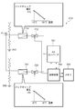
装着体100の状態測定部200の機能構成を示す図である。
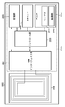
本体部300の機能構成を示す図である。
状態監視装置における体温測定処理の流れを示す図である。
半導体温度センサの特性を示す図である。
状態測定部200のセンサ部211の回路構成を示す図である。
状態測定部200の回路部212の回路構成を示す図である。
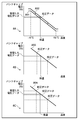
本体部300の信号処理部304における体温データ算出処理の内容を説明するための図である。
装着体100の状態測定部900の機能構成を示す図である。
装着体100の状態測定部1000の機能構成を示す図である。
装着体100の状態測定部1100の機能構成を示す図である。
装着体1200の外観を示す図である。
装着体1300の外観を示す図である。
装着体1300の外観を示す図である。
以下、必要に応じて添付図面を参照しながら本発明の各実施形態の詳細を説明する。
[第1の実施形態]
<状態監視装置の構成>
はじめに状態監視装置の構成について説明する。本発明の一実施形態に係る状態監視装置は、装着体100と本体部300とにより構成される。そして、図1Aに示すように、装着体100は、例えばベッド上にオムツQをはいて横臥または仰臥した乳幼児P等に装着され、本体部300は乳幼児Pから所定距離だけ離れた位置に固定される。
<状態監視装置の構成>
はじめに状態監視装置の構成について説明する。本発明の一実施形態に係る状態監視装置は、装着体100と本体部300とにより構成される。そして、図1Aに示すように、装着体100は、例えばベッド上にオムツQをはいて横臥または仰臥した乳幼児P等に装着され、本体部300は乳幼児Pから所定距離だけ離れた位置に固定される。
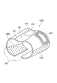
図1Bは装着体100の外観構成を示す図であり、装着体100は、乳幼児Pの体温測定部位に装着されるカーラ230と、半導体温度センサを有する処理部210及びアンテナ部220からなる状態測定部200(RFID)とを備える。
カーラ230は、更に、処理部210が配され乳幼児Pの体温測定部位である大腿部に接触する接触部231と、アンテナ部220が配され乳幼児の体温測定部位である大腿部に接触部231を接触させた状態を維持するための巻き付け部232とを備える。
巻き付け部232は略剛体であり、ポリエチレン、ポリプロピレン、環状ポリオレフィン、ポリカーボネート、ポリエチレンテレフタレート、ポリブチレンテレフタレート、ポリメチルペンテン1、或いはそれらの混合物、又はそれらにSEBSなどの柔軟化剤をブレンドすることにより得られた素材等により構成されている。
巻き付け部232は、体温測定部位である大腿部の外周面を把持する2つの把持曲面を備え、当該2つの把持曲面は略C字形状をしている。また、径方向に弾性変形することで、拡径可能となっている。かかる構成により、接触部231を体温測定部位である大腿部に接触させた状態を維持させることができる。このときの巻き付け部232の曲げ応力は30~130MPaであることが好ましい。なお、巻き付け部232の素材は、拡径可能な可撓性の素材であれば上記素材に限定されず、例えばセラミックス、ステンレスなどの金属類であってもよい。
巻き付け部232の2つの把持曲面は、更に、体温測定部位である大腿部の外周面の円周方向に沿ったスリットをそれぞれ有している。また、当該スリットを介して隣り合う把持曲面は互いに外径が異なっている。このような形状にすることにより、上腕部や大腿部のようなテーパ形状の部位に対して、装着性を向上させることができる。
なお、巻き付け部232におけるスリットの数や外径の大きさ等は、上述の例に限定されないものとする。
半導体温度センサを有する処理部210は、接触部231の内側に設けられ、アンテナ部220は、巻き付け部232の内側に設けられている。なお、アンテナ部220は、必ずしも巻き付け部232の内側に設けられている必要はなく、巻き付け部232の外側に設けられていてもよい。
接触部231は、処理部210と体温測定部位との接触性を高めるため、内側方向に凸形状を有している。
一方、本体部300は、体温などを表示する表示部や、ブザー等の報知手段、無線により処理部よりデータを読み取る読取部、各種情報を入力する入力部、記憶部、マイクロコンピュータなどのコントロール部(CPU)、i-モード等を用いてインターネット等の情報通信ネットワークと通信を行う外部通信部等を備える(詳細は後述)。
更に、本体部300のコントロール部は、コントロール部により実行され本体部300全体を制御する制御プログラムや各種データ等を記憶するROMと、ワークエリアとして各種データを一時的に記憶するRAMを備える。
このような構成のもと、本体部300では、例えば予防接種(インフルエンザ、おたふくかぜ、ポリオ、百日咳、風疹、麻疹、結核等の予防接種)の情報や、過去の投薬データ(薬剤名、投与量、投与日時などの情報:アレルギー反応を回避した投薬を行なうために必要)を、入力部を介して入力し、記憶、表示させることできる。
また、入力部を介して入力項目を適宜選択することで、体温、体重(投与量の決定に必要)、血圧、脈拍、血糖値等を入力したり、記憶、表示させたりすることができる。本体部300がこのような機能を有することで、本体部300は母子健康手帳としての役割を果たすことも可能となる。
なお、このような状態監視装置を病院等で使用する場合にあっては、本体部300が同時に複数の状態測定部と通信を行う必要がある。このため、状態測定部は、アンチコリージョン型に形成されていることが好ましい。
更に、図1Aにおいては不図示であるが、サーバ(データ処理装置)を別途設け、本体部300を接続し、当該サーバ上に管理サイト/医療サイトを形成するようにしてもよい。その際、乳幼児PのIDと関連付けして、脈拍、呼吸、血圧、体温、血中酸素飽和度、血糖等の生体情報をリアルタイムに収集、集計、分析できるように構成してもよい。このような構成とすることで、感染症等による急激な体温の上昇、うつ伏せ寝や嘔吐等に起因する窒息による呼吸停止などに対しても、いち早く異常を把握することが可能となるからである。
更に、担当医の机上に管理パソコン等を設置し、担当医が随時、被検者(例えば乳幼児P)の身体状態を把握、監視できるようにするとともに、被検者の異常通報を受けたり、適宜看護士の待機部屋に指示を出したり、ハンディ・ナースコールで看護士に連絡したりすることができるように構成してもよい。
<状態測定部の機能構成>
次に、状態測定部200の機能構成について説明する。図2は、アンテナ部220と処理部210とを備える状態測定部200(RFID)の機能構成を示す図である。
次に、状態測定部200の機能構成について説明する。図2は、アンテナ部220と処理部210とを備える状態測定部200(RFID)の機能構成を示す図である。
図2において、202は無線インターフェイス部であり、整流回路や昇圧回路等を備える。無線インターフェイス部202では、アンテナ部220において生じた交流電圧を、所定の直流電圧に変換し、記憶部203及びマイクロコンピュータなどのコントロール部(CPU)205に供給する。なお、コントロール部205は、コントロール部205により実行され、状態測定部200全体の制御を行う制御プログラムや各種データを記憶するROMと、ワークエリアとして各種データを一時的に記憶するRAMとを備える。また、コントロール部205において取得された電圧データ(被検者の体温に対応するデータ)を各種データとともに、所定の形式によりアンテナ部220を介して本体部300に送信する。
記憶部203は、後述する感温部204の校正データや、処理部210固有の識別情報等を記憶する。また、記憶部203はEEPROMを備え、コントロール部205において取得された電圧データが記憶できるように構成されている。このように、状態測定部200自体に記憶機能を持たせることにより、乳幼児Pが別のベッドや別の部屋に移し変えられた場合であっても、本体部300を用いて当該電圧データを読み出し当該乳幼児Pの過去の体温測定結果を表示させることが可能となる。
なお、記憶部203に記憶される電圧データをアンチコリージョン型とし、本体部300が、間違った乳幼児P’(不図示)の情報を取得することがないように構成してもよい。更に、アンテナ部220から出力される信号を暗号化処理することで、セキュリティ機能を強化させるように構成してもよい。
感温部204は、半導体温度センサを備えるセンサ部211と、センサ部211の出力を処理する回路部212とを備える。半導体温度センサにはC-MOS温度センサ等が用いられるものとする。半導体温度センサは温度変化に対してほぼリニアにアナログ出力する特性を有しており、小型化及び処理部210との一体化が可能である。また、35~42℃の間において0.01℃の温度分解能を実現することができる。なお、センサ部211及び回路部212の回路構成の詳細は、後述する。
処理部210は、幅W×長さLが5mm×5mm、厚さTが1.5mm程度の大きさとなっている。なお、処理部210は、生体を通過可能な周波数を有する電磁波による通信(送受信)が可能であれば、どのような周波数の電磁波であってもよいが、本実施形態では、例えば13.56MHzの電磁波を用いるものとする。
上述したようにアンテナ部220は、巻き付け部232に実装されるため、処理部内に組み込まれた従来のアンテナ部に比べ、径を大きくすることができる。なお、アンテナ部の形状は特定の形状に限定されるものではないが、円形、正方形、長方形などの形状を有していることが好ましい。また、円形状の場合にあっては、直径Dが20mm~40mm、厚さTが1mm程度であることが好ましく、また、長方形の場合にあっては、長辺の長さをL1、短辺の長さをL2とした場合、L1=20mm、L2=40mmであって、厚さTが1mm程度であることが好ましい。
なお、カーラ230を交換したい場合や、水気などでカーラ230の汚れを取り除きたい場合、あるいは処理部やアンテナ部を他のカーラへ入れ替えたい場合にも対応できるよう、状態測定部200は、カーラ230に対して着脱可能に構成されているものとする。
<本体部の機能構成>
次に、本体部300の機能構成について説明する。図3は、本体部300の機能構成を示す図である。
次に、本体部300の機能構成について説明する。図3は、本体部300の機能構成を示す図である。
図3において、310は読取部であり、アンテナ部301と、無線インターフェイス部302と、信号変換部303と、信号処理部304とを備える。
アンテナ部301は、状態測定部200のアンテナ部220との間で磁気結合することで誘導起電力が発生し、処理部210に電源を供給したり、処理部210よりデータを受信したりする。
無線インターフェイス部302は、アンテナ部301を介して処理部210に電源を供給するために、アンテナ部301に印加する電圧を制御したり、アンテナ部301を介して処理部210より受信したデータを信号変換部303に送信したりする。
信号変換部303では、無線インターフェイス部302より送信されたデータをデジタルデータに変換し、信号処理部304に送信する。
信号処理部304では、信号変換部303より受信したデジタルデータを処理し、体温データを算出する。具体的には、受信したデジタルデータに含まれる、電圧データと校正データとに基づいて体温データを算出する。また、算出した体温データを、受信したデジタルデータに含まれる識別情報とともにコントロール部311に送信する。
コントロール部311では、無線インターフェイス部302、信号変換部303、信号処理部304の動作を制御する。また、信号処理部304から送信された体温データを、識別情報とともに記憶部312に収納したり、表示部313に表示したりする。更に、記憶部312に収納された体温データを、識別情報とともに外部通信部314を介して、他の情報処理装置(外部通信部314を介して有線接続された他の情報処理装置)に送信したりする。
入力部315では、体温測定における設定を入力し、条件を選択したりする。また、報知手段316では、ブザー、バイブレータ、光などにより体温データが異常であること、あるいは測定が終了したことなどをユーザに知らせる。
<状態監視装置における状態監視機能>
次に、状態監視装置における状態監視機能について説明する。状態監視を行うにあたり、ユーザは、感温部204を有する処理部210が乳幼児Pに対して接触するように、装着体100を乳幼児Pの上腕部や大腿部などの体温測定部位に装着する。
次に、状態監視装置における状態監視機能について説明する。状態監視を行うにあたり、ユーザは、感温部204を有する処理部210が乳幼児Pに対して接触するように、装着体100を乳幼児Pの上腕部や大腿部などの体温測定部位に装着する。
装着が完了すると、ユーザは測定開始の時間をカウントするカウント機能の動作開始を指示する。あるいは、入力部315などで測定開始時刻設定(時間設定)を指示する。これにより、状態監視機能が開始される。
具体的には、入力部315を介して予め設定入力された時間条件、例えば装着体100を、乳幼児Pに装着した後に、測定開始指示を入力した時点、あるいは所定の温度上昇が確認できた時点等を基点として、例えば5分後に状態測定部200に対して読取部310から所定の周波数(例えば13.56MHz)の電磁波を送信する。そして、その信号と同期して得られる半導体温度センサの出力を含む各種データ(電圧データ、校正データ等)を状態測定部200より読み取る。
そして、読み取った各種データに基づいて算出した体温データを、記憶部312に記憶する。また、記憶した体温データを閾値と比較する。閾値は、例えば、上限値を37.5℃、下限値を35.5℃と設定されているものとする。なお、上限値/下限値は、所定期間の体温トレンド情報に基づいてユーザが任意に設定入力できるよう構成されているものとする。
閾値との比較の結果、体温データが異常であると判断した場合には、報知手段316がアラームを発生する。また、体温測定が終了するとブザー、バイブレータ、光などの報知手段316が動作し、ユーザに報知する。
更に、体温データを異常と判断した場合にあっては、表示部313に、「発熱」と表示する。また、ユーザが入力部315を介してその旨の情報を入力した場合にあっては、体温データと対応付けて、記憶部312にその旨の情報を記憶する。なお、異常と判断した場合には、再度体温測定を行うように構成してもよい。
一方、体温データが異常でないと判断した場合には、記憶部312が測定した体温データを記憶するとともに、表示部313が体温データを表示する。なお、体温データの表示は、測定年月日時とともに行うものとする。
なお、体温データを異常と判断した場合にあっては、本体部300と外部通信部314を介して接続されたパルスオキシメータにおいて測定された脈拍、血中酸素飽和度(SPO2)等を取得するようにしてもよい。また、被検者に投薬を行った場合にあっては、入力部315を介して投薬データを入力できるようにしてもよい。更に、取得した脈拍、血中酸素飽和度や、入力された投薬データを、体温データと対応付けて記憶するようにしてもよい。これにより、体温データのトレンドグラフを表示する際に、当該取得した脈拍、血中酸素飽和度、入力された投薬データを重ねて表示することが可能となり、インフルエンザ、RS(Respiratory Syncytial)ウイルス等の感染症等による呼吸器系疾患を容易に把握することが可能となるからである。
<状態監視装置における体温測定処理の流れ>
次に、状態監視装置における体温測定処理の流れについて説明する。図4は、状態監視装置における体温測定処理の流れを示す図である。
次に、状態監視装置における体温測定処理の流れについて説明する。図4は、状態監視装置における体温測定処理の流れを示す図である。
図4に示すように、本体部300が起動した後に、本体部300のアンテナ部301が所定の時間間隔で励磁されると、所定の周波数、例えば13.56MHzの電磁波により、アンテナ部301とアンテナ部220とが磁気結合され、本体部300から装着部の状態測定部200に対して電源が供給される(ステップS401)。
電源が供給された状態測定部200では、処理部210が起動し、状態測定部200が体温測定の精度に影響を与える状態になっていないか否かが判定される(ステップS411)。なお、「状態測定部200が体温測定の精度に影響を与える状態」とは、一定値以上の電圧が励磁され処理部210やアンテナ部220が発熱することにより、体温測定の精度に影響を与える可能性が高い状態をいう。
状態測定部200が体温測定の精度に影響を与える状態になっていると判定された場合、処理部210では、以降の処理は行わない。この場合、本体部300では、電源供給を行ってから一定時間内に状態測定部200よりデータ送信がないと判断し、表示部313にエラー表示を行う(ステップS421)。このとき、エラー表示だけでなく、報知手段316によるアラーム等の報知を行ってもよい。
一方、状態測定部200が体温測定の精度に影響を与える状態になっていないと判定された場合には、処理部210が処理を開始する。具体的には、予め設定された判定レンジ(詳細は後述)に切り替えた後、センサ部211内の半導体温度センサに電流を流し、バンドギャップ電圧(詳細は後述)を検出する(ステップS413、S414)。
更に、回路部212が当該検出されたバンドギャップ電圧を処理し、コントロール部205が電圧データを取得する(ステップS415)。取得した電圧データは、記憶部203に記憶された校正データ及び識別情報とともに、本体部300に送信される(ステップS416、S402)。
本体部300では、状態測定部200より送信された電圧データ及び校正データに基づいて体温データを算出する。更に、算出した体温データを、識別情報と対応付けて記憶部312に記憶するとともに表示部313に表示する(ステップS421)。
<半導体温度センサの説明>
次に、センサ部211が有する半導体温度センサについて説明する。図5は、半導体温度センサの特性を示す図である。なお、本実施形態のセンサ部211が有する半導体温度センサは、P型半導体とN型半導体とを結合することにより構成され、直流電流を流した際の結合部(ジャンクション)に生じる電圧(バンドギャップ電圧Vb)を検出する構成となっている(図5の5A)。
次に、センサ部211が有する半導体温度センサについて説明する。図5は、半導体温度センサの特性を示す図である。なお、本実施形態のセンサ部211が有する半導体温度センサは、P型半導体とN型半導体とを結合することにより構成され、直流電流を流した際の結合部(ジャンクション)に生じる電圧(バンドギャップ電圧Vb)を検出する構成となっている(図5の5A)。
かかる半導体温度センサの場合、図5の5Bに示すように、バンドギャップ電圧Vbと温度とは、概ね-40℃~+150℃の広範囲において線形性を有している。このため、検出したバンドギャップ電圧Vbに基づいて、温度を算出することができる。
かかる半導体温度センサは、サーミスタと比較して、経時変化に強く、かつノイズの影響を受けにくいといった利点を有している。
<センサ部の回路構成>
次に、センサ部211の回路構成について説明する。図6は、図5の5Aに示す半導体温度センサを用いて構成されたセンサ部211の回路構成を示す図である。
次に、センサ部211の回路構成について説明する。図6は、図5の5Aに示す半導体温度センサを用いて構成されたセンサ部211の回路構成を示す図である。
図6において、601は定電流回路であり、コントロール部205より供給される電圧Vccに基づいて、各半導体温度センサに流す電流が均一になるように調整する。
602は半導体温度センサであり、定電流回路601の下流側において、定電流回路601に対して直列に接続されている。なお、半導体温度センサ602は定電流回路601に対して複数接続されており、それぞれの半導体温度センサは、互いに並列に接続されている。
このように、複数の半導体温度センサを並列に接続しているのは、半導体温度センサの個体差の影響を排除するためである。より高精度な体温測定を実現するためには、半導体温度センサの個体差の影響も無視することができず、センサ部211では、複数の半導体温度センサを並列に接続し平均値をとることで、個体差の影響を排除することとしている。このため、センサ部211からは、各半導体温度センサより出力された電圧Vb1、Vb2、・・・Vbnの平均値Vb_avgが出力されることとなる。
なお、各半導体温度センサに電流を流すのは1回に限られず、複数回流すように構成してもよい。その場合、センサ部211からは、平均値Vb_avgが複数回出力されることとなる。
<回路部の回路構成>
次に、回路部212の回路構成について説明する。図7は、回路部212の回路構成を示す図である。
次に、回路部212の回路構成について説明する。図7は、回路部212の回路構成を示す図である。
図7に示すように、回路部212は、比較・増幅器711とアナログスイッチ712とを介してA/Dコンバータ701に接続される系と、比較・増幅器721とアナログスイッチ722とを介してA/Dコンバータ701に接続される系の2系統から構成されている。
前者の系(第1の系)では、センサ部211より出力された電圧Vb_avgを、-40℃~+150℃の測定レンジでA/Dコンバータ701に出力する。一方、後者の系(第2の系)では、センサ部211より出力された電圧Vb_avgを、20℃~50℃の測定レンジでA/Dコンバータ701に出力する。
第1の系を用いて出力するか、第2の系を用いて出力するかは(つまり、測定レンジは)、制御回路702からの信号に基づいてアナログスイッチ712、722を切り替えることにより制御される。より高精度な体温測定を行う場合には、第2の系が選択されることとなる。
A/Dコンバータ701に入力された電圧Vb_avgは、A/Dコンバータ701においてA/D変換され、デジタルデータとして制御回路702に入力される。
制御回路702に入力されたデジタルデータは、無線インターフェイス部202に送信される。
なお、センサ部211より電圧Vb_avgが複数回出力される場合にあっては、それぞれのデジタルデータをメモリ703に一時的に格納し、制御回路702において、メモリ703に格納された全てのデジタルデータの平均値を算出した後に、無線インターフェイス部202に送信されることとなる。
<本体部における体温データ算出処理>
次に、本体部300の信号処理部304において体温データを算出するための処理について説明する。図8は、信号処理部304において体温データを算出するための処理の内容を説明するための図である。
次に、本体部300の信号処理部304において体温データを算出するための処理について説明する。図8は、信号処理部304において体温データを算出するための処理の内容を説明するための図である。
信号処理部304では、基準となる半導体温度センサにおける、電圧データと体温データとの対応関係を示すグラフ(関数)を、校正データに基づいて補正した後に、受信した電圧データを代入することにより、体温データを導出する。
図8の8Aは、1種類の温度に対応する1種類の校正データを受信した場合における補正処理を示す図である。図8の8Aに示すように、1種類の温度に対応する1種類の校正データを受信した場合には、基準となる半導体温度センサにおける、電圧データと体温データとの対応関数のオフセット値を調整する。具体的には、グラフ801を全体として矢印方向に平行移動させ、グラフ802を得る。
信号処理部304では、状態測定部200より受信した電圧データを、当該平行移動後のグラフ802に代入することで、体温データを導出する。
図8の8Bは、2種類の温度に対応する2種類の校正データを受信した場合における補正処理を示す図である。図8の8Bに示すように、2種類の温度に対応する2種類の校正データを受信した場合には、当該2点を通る直線803を算出し、これを半導体温度センサにおける電圧データと体温データとの対応関係を示すグラフとする。
信号処理部304では、状態測定部200より受信した電圧データを、当該算出された直線803に代入することで、体温データを導出する。
図8の8Cは、3種類以上の温度に対応する3種類以上の校正データを受信した場合における補正処理を示す図である。図8の8Cに示すように、3種類以上の温度に対応する3種類以上の校正データを受信した場合には、当該3点以上の点に基づいて、最小2乗法により回帰直線804を算出し、これを半導体温度センサにおける電圧データと体温データとの対応関係を示すグラフとする。
信号処理部304では、状態測定部200より受信した電圧データを、当該算出された回帰直線804に代入することで、体温データを算出する。
以上の説明から明らかなように、本実施形態にかかる状態監視装置では、装着体をカーラ型とし、その巻き付け部にアンテナ部を配するとともに接触部に半導体温度センサを有する処理部を配する構成とした。
これにより、アンテナ部の径を大きくすることが可能となり、離れた位置との間であっても、少ない消費電力でデータの送受信を行うことが可能となった。この結果、被検者に装着する装着体の軽量化、低コスト化を実現しつつ、測定精度が維持された体温測定を所定の時間間隔で自動的に行うことが可能となった。
また、本実施形態に係る状態監視装置では、半導体温度センサを適用するにあたり、
・半導体温度センサの個体差の影響を排除するため、センサ部において、複数の半導体温度センサを並列に接続する構成とした。
・測定誤差を排除するため、1回の体温測定に際して、センサ部に対して複数回電流を流し、その平均値を出力する構成とした。
・処理部の個体差の影響を排除するため、処理部内の記憶部に処理部ごとに校正データを記憶しておき、本体部に電圧データを送信する際に、合わせて校正データを送信する構成とした。この結果、更に高精度な体温測定を実現することが可能となった。
・半導体温度センサの個体差の影響を排除するため、センサ部において、複数の半導体温度センサを並列に接続する構成とした。
・測定誤差を排除するため、1回の体温測定に際して、センサ部に対して複数回電流を流し、その平均値を出力する構成とした。
・処理部の個体差の影響を排除するため、処理部内の記憶部に処理部ごとに校正データを記憶しておき、本体部に電圧データを送信する際に、合わせて校正データを送信する構成とした。この結果、更に高精度な体温測定を実現することが可能となった。
[第2の実施形態]
上記第1の実施形態では、被検者の状態として体温データの監視を行う場合について説明したが、本発明はこれに限定されず、例えば、被検者の体動・体位を監視するように構成してもよい。以下、本実施形態の詳細について、上記第1の実施形態との相違点を中心に説明する。
上記第1の実施形態では、被検者の状態として体温データの監視を行う場合について説明したが、本発明はこれに限定されず、例えば、被検者の体動・体位を監視するように構成してもよい。以下、本実施形態の詳細について、上記第1の実施形態との相違点を中心に説明する。
<状態測定部の機能構成>
図9は、本実施形態における状態測定部900の機能構成を示す図である。図9において、906は体動検出手段であり、被検者の体動・体位情報を測定する。体動検出手段906としては、例えば、MEMS型の3軸加速度センサが用いられるものとする。なお、MEMS型の3軸加速度センサは、検知機構の違いにより、ピエゾ抵抗型、静電容量型、熱検知型の3種類に大別することができる。本実施形態における状態測定部900は、そのうちのいずれの検知機構を用いても構わない。
図9は、本実施形態における状態測定部900の機能構成を示す図である。図9において、906は体動検出手段であり、被検者の体動・体位情報を測定する。体動検出手段906としては、例えば、MEMS型の3軸加速度センサが用いられるものとする。なお、MEMS型の3軸加速度センサは、検知機構の違いにより、ピエゾ抵抗型、静電容量型、熱検知型の3種類に大別することができる。本実施形態における状態測定部900は、そのうちのいずれの検知機構を用いても構わない。
また、体動検出手段906は、MEMS型の3軸加速度センサに限定されるものではなく、例えば、3軸方向にそれぞれ配された傾斜センサやジャイロスコープを用いても良い。
体動検出手段906は、所定の時間間隔で本体部300より状態測定部900が励磁されることにより起動し、体動・体位情報を検出する。検出された体動・体位情報は、半導体温度センサの起動により検出された電圧データ等とともに、本体部300に送信される(なお、検出された体動・体位情報は、半導体温度センサの起動により検出された電圧データと対応付けて、記憶部203が有するEEPROMに記憶される)。
本体部300の表示部313では、状態測定部900より送信された各種データを受信し、表示する。これにより、ユーザは体温データだけでなく、体温データのみでは確認できなかった、寝返りや咳による体動・体位情報を確認することができる。
[第3の実施形態]
上記第1の実施形態では、被検者の状態として体温測定を行う場合について説明したが、本発明はこれに限定されず、例えば、被検者の発汗状態を検知するよう構成してもよい。以下、本実施形態の詳細について、上記第1の実施形態との相違点を中心に説明する。
上記第1の実施形態では、被検者の状態として体温測定を行う場合について説明したが、本発明はこれに限定されず、例えば、被検者の発汗状態を検知するよう構成してもよい。以下、本実施形態の詳細について、上記第1の実施形態との相違点を中心に説明する。
<状態測定部の機能構成>
図10は、本実施形態における状態測定部1000の機能構成を示す図である。図10において、1006は湿度センサであり、被検者の発汗状態を測定する。湿度センサ1006としては、例えば、MEMS型の湿度センサ(高分子膜湿度センサやセラミック湿度センサ等)が用いられるものとする。
図10は、本実施形態における状態測定部1000の機能構成を示す図である。図10において、1006は湿度センサであり、被検者の発汗状態を測定する。湿度センサ1006としては、例えば、MEMS型の湿度センサ(高分子膜湿度センサやセラミック湿度センサ等)が用いられるものとする。
なお、高分子膜湿度センサは、セルロース系の親水性高分子の乾湿材料により吸着される水分量に応じて、当該乾湿材料の静電容量が変化する性質を利用した、静電容量型のセンサであることが好ましく、またセラミック湿度センサは、MgCr2O4-TiO2系セラミックス、TiO2-V2O5系セラミックス湿度センサであることが好ましい。
湿度センサ1006は、所定の時間間隔で本体部300により状態測定部1000が励磁されることにより起動し、発汗状態を検出する。検出された発汗状態は、半導体温度センサの起動により検出された電圧データ等とともに、本体部300に送信される(なお、検出された発汗状態は、半導体温度センサの起動により検出された電圧データと対応付けて、記憶部203が有するEEPROMに記憶される)。
本体部300の表示部313では、状態測定部900より送信された各種データを受信し、表示する。これによりユーザは、体温データだけでなく、体温データのみでは確認できなかった、熱が下がる前の発汗(快復する予兆)や体調不良による発汗などを確認することが可能となる。
[第4の実施形態]
上記第2及び第3の実施形態では、本体部300において、体温データと体動・体位情報との組み合わせ、または体温データと発汗情報との組み合わせについて表示できるよう構成したが、本発明はこれに限定されない。例えば、体温データと体動・体位情報と発汗情報との組み合わせについて表示できる構成としてもよい。以下、本実施形態の詳細について、上記第1の実施形態との相違点を中心に説明する。
上記第2及び第3の実施形態では、本体部300において、体温データと体動・体位情報との組み合わせ、または体温データと発汗情報との組み合わせについて表示できるよう構成したが、本発明はこれに限定されない。例えば、体温データと体動・体位情報と発汗情報との組み合わせについて表示できる構成としてもよい。以下、本実施形態の詳細について、上記第1の実施形態との相違点を中心に説明する。
<状態測定部の機能構成>
図11は、本実施形態における状態測定部1100の機能構成を示す図である。図11において、906は体動検出手段であり、被検者の体動・体位情報を測定する。体動検出手段906としては、例えば、MEMS型の3軸加速度センサが用いられるものとする。なお、MEMS型の3軸加速度センサは、検知機構の違いにより、ピエゾ抵抗型、静電容量型、熱検知型の3種類に大別することができる。本実施形態では、そのうちのいずれの検知機構を用いても構わない。
図11は、本実施形態における状態測定部1100の機能構成を示す図である。図11において、906は体動検出手段であり、被検者の体動・体位情報を測定する。体動検出手段906としては、例えば、MEMS型の3軸加速度センサが用いられるものとする。なお、MEMS型の3軸加速度センサは、検知機構の違いにより、ピエゾ抵抗型、静電容量型、熱検知型の3種類に大別することができる。本実施形態では、そのうちのいずれの検知機構を用いても構わない。
また、体動検出手段906は、MEMS型の3軸加速度センサに限定されるものではなく、例えば、3軸方向にそれぞれ配された傾斜センサやジャイロスコープを用いても良い。
また、図11において、1006は湿度センサであり、被検者の発汗状態を測定する。湿度センサ1006としては、例えば、MEMS型の湿度センサ(高分子膜湿度センサやセラミック湿度センサ等)が用いられるものとする。
なお、高分子膜湿度センサは、セルロース系の親水性高分子からなる乾湿材料により吸着される水分量に応じて、当該乾湿材料の静電容量が変化する性質を利用した、静電容量型のセンサであることが好ましく、またセラミック湿度センサとしては、MgCr2O4-TiO2系セラミックス、TiO2-V2O5系セラミックス湿度センサであることが好ましい。
体動検出手段906及び湿度センサ1006は、所定の時間間隔で本体部300により状態測定部1100が励磁されることで起動し、それぞれ被検者の体動・体位情報及び発汗状態を検出する。検出された体動・体位情報及び発汗状態は、半導体温度センサの起動により検出された電圧データ等とともに、本体部300に送信される(なお、検出された体動・体位情報及び発汗状態は、半導体温度センサの起動により検出された電圧データと対応付けて、記憶部203が有するEEPROMに記憶される)。
本体部300の表示部313では、状態測定部1100より送信された各種データを受信し、表示する。これによりユーザは、体温データだけでなく、体温データのみでは確認できなかった、寝返りや咳による体動・体位情報を確認することが可能となる。更に、体温データのみでは確認できなかった、熱が下がる前の発汗(快復する予兆)や体調不良による発汗などを確認することも可能となる。
[第5の実施形態]
上記第1乃至4の実施形態では、カーラ230の巻き付け部232の表面性状について特に言及しなかったが、巻き付け部232は被検者の肌と接触することから、例えば、絹、綿、麻、ナイロン、ポリエステルといった繊維や、人工皮革、不織布などの衣類の素材に成り得る素材であることが好ましい。
上記第1乃至4の実施形態では、カーラ230の巻き付け部232の表面性状について特に言及しなかったが、巻き付け部232は被検者の肌と接触することから、例えば、絹、綿、麻、ナイロン、ポリエステルといった繊維や、人工皮革、不織布などの衣類の素材に成り得る素材であることが好ましい。
また、上記第1乃至4の実施形態では、カーラ230の巻き付け部232の素材の可撓性を利用して、カーラ230を被検者の体温測定部位に装着する構成としたが、本発明はこれに限定されない。例えば、図12に示すように、巻き付け部232の一方の内面先端に雄型面ファスナ1230を、もう一方の外面先端に雌型面ファスナ1240を設け、雄型面ファスナ1230と雌型面ファスナ1240とを結合させることで、カーラ230を被検者の体温測定部位に装着する構成としてもよい。この場合、雄型面ファスナ1230と雌型面ファスナ1240とは、ワンタッチ式係止部材として機能することとなる。なお、雄型面ファスナ1230と雌型面ファスナ1240は、被検者の測定部位の径に応じた範囲に対応して先端部に設けられているものとする。
また、上記第1乃至4の実施形態では、巻き付け部232がスリットを有し、当該スリットを介して隣り合う把持曲面の外径が互いに異なる形状であるとしたが、本発明はこれに限定されず、例えば、図12に示すように、長手方向(紙面手前側から奥側)に向かって把持曲面の曲率が徐々に変化していく構成としてもよい。この場合、装着体1200は、上面(接触部231の上方)から見ると、扇形状を有することとなる。
[第6の実施形態]
上記第1乃至第4の実施形態では、カーラ230の巻き付け部232の素材の可撓性を利用して、被検者の体温測定部位に装着する構成としたが、本発明はこれに限定されない。例えば、カーラ230の外面にバックル1350付きのベルト1340を付すように構成してもよい(図13)。バックル1350付きのベルト1340を付すことにより、ベルトの長さ調整が可能となり、被検者の体温測定部位の径の違いに対応することが可能となる。この場合、バックル1350は、ワンタッチ式係止部材として機能することとなる(図14)。
上記第1乃至第4の実施形態では、カーラ230の巻き付け部232の素材の可撓性を利用して、被検者の体温測定部位に装着する構成としたが、本発明はこれに限定されない。例えば、カーラ230の外面にバックル1350付きのベルト1340を付すように構成してもよい(図13)。バックル1350付きのベルト1340を付すことにより、ベルトの長さ調整が可能となり、被検者の体温測定部位の径の違いに対応することが可能となる。この場合、バックル1350は、ワンタッチ式係止部材として機能することとなる(図14)。
なお、バックル250は、ワンタッチ式であり、係止を確実にするものであれば、形状・材質などは何でも構わないが、剛体であることが好ましく、例えば、ポリエチレン、ポリプロピレン、環状ポリオレフィンなどのプラスチック材や、セラミックス、ステンレスなどの金属類であることが好ましい。
[第7の実施形態]
上記第1の実施形態では、本体部300が、アンテナ部301、無線インターフェイス部302、信号変換部303、信号処理部304、コントロール部311、記憶部312、表示部313、外部通信部314、入力部315を備えるものとして説明したが、本体部300の機能構成はこれに限定されない。
上記第1の実施形態では、本体部300が、アンテナ部301、無線インターフェイス部302、信号変換部303、信号処理部304、コントロール部311、記憶部312、表示部313、外部通信部314、入力部315を備えるものとして説明したが、本体部300の機能構成はこれに限定されない。
例えば、外部通信部314を介して外部機器を通信可能に接続し、表示部313、入力部315等のユーザインタフェース機能を、当該外部機器に持たせる構成としてもよい。この場合、本体部300は、状態測定処理の結果を当該外部機器に伝達する中継装置として機能することとなる。
このような構成とすることで、乳幼児Pから所定距離だけ離れた位置に固定される本体部300を小型化できる一方、本体部300による状態測定処理を遠隔に配置した外部機器から操作、監視することが可能となる。
本発明は上記実施の形態に制限されるものではなく、本発明の精神及び範囲から離脱することなく、様々な変更及び変形が可能である。従って、本発明の範囲を公にするために、以下の請求項を添付する。
本願は、2009年2月26日提出の日本国特許出願特願2009-043250、特願2009-043251、特願2009-043252、特願2009-043253、特願2009-043254、特願2009-043255、特願2009-043256、特願2009-043257を基礎として優先権を主張するものであり、その記載内容の全てを、ここに援用する。
Claims (10)
- 被検者に装着される装着体と、該装着体と通信する本体部とを備え、該被検者の状態を監視する状態監視装置であって、
前記装着体は、
前記被検者の測定部位に接触する接触面と、
前記接触面を前記測定部位に接触させた状態を維持するための巻き付け部であって、前記被検者の測定部位を含む部位の外周面を把持する2つの把持曲面を有し、かつ該把持曲面が径方向に弾性変形することにより該部位の径に応じて拡径可能である巻き付け部と、
前記接触面に配され、起動時に前記被検者の測定部位の体温に応じたデータを出力する処理部と、
前記巻き付け部に配され、誘導起電力を発生し前記処理部を起動させるとともに、前記処理部より出力されたデータを前記本体部に送信するアンテナ部と、を備え、
前記本体部は、
所定の時間間隔で電磁波を出力することで、前記アンテナ部に誘導起電力を発生させるとともに、前記アンテナ部より送信されたデータを受信する通信部と、
前記通信部において受信されたデータに基づいて算出された前記被検者の状態に関する情報を表示する表示部と
を備えることを特徴とする状態監視装置。 - 前記処理部は前記接触面に着脱可能に配され、前記アンテナ部は前記巻き付け部に着脱可能に配されていることを特徴とする請求項1に記載の状態監視装置。
- 前記巻き付け部は、前記把持曲面により把持される前記外周面の円周方向に沿って、スリットが形成されていることを特徴とする請求項1または2に記載の状態監視装置。
- 前記巻き付け部が有する前記把持曲面は、前記部位の長手方向に沿って、異なる曲率を有していることを特徴とする請求項1乃至3のいずれか1項に記載の状態監視装置。
- 前記巻き付け部が有する前記把持曲面のうち、前記スリットを介して互いに隣り合う把持曲面は、異なる曲率を有していることを特徴とする請求項3に記載の状態監視装置。
- 前記処理部は、更に、起動時に前記被検者の測定部位の体動または体位に応じたデータを出力することを特徴とする請求項1に記載の状態監視装置。
- 前記処理部は、更に、起動時に前記被検者の測定部位の湿度に応じたデータを出力することを特徴とする請求項1または6に記載の状態監視装置。
- 前記巻き付け部は、前記2つの把持曲面の先端に、それぞれの先端部を係止する係止部材を更に備えることを特徴とする請求項1に記載の状態監視装置。
- 前記係止部材は、前記2つの把持曲面にそれぞれ設けられた雄型面ファスナと雌型面ファスナであることを特徴とする請求項8に記載の状態監視装置。
- 前記係止部材は、バックルであることを特徴とする請求項8に記載の状態監視装置。
Priority Applications (1)
| Application Number | Priority Date | Filing Date | Title |
|---|---|---|---|
| CN2010800096305A CN102333479A (zh) | 2009-02-26 | 2010-02-09 | 状态监视装置 |
Applications Claiming Priority (16)
| Application Number | Priority Date | Filing Date | Title |
|---|---|---|---|
| JP2009-043254 | 2009-02-26 | ||
| JP2009-043252 | 2009-02-26 | ||
| JP2009043257A JP5243301B2 (ja) | 2009-02-26 | 2009-02-26 | 生体動態測定装置 |
| JP2009-043251 | 2009-02-26 | ||
| JP2009043255A JP2010194131A (ja) | 2009-02-26 | 2009-02-26 | 生体動態測定装置 |
| JP2009043252A JP2010194129A (ja) | 2009-02-26 | 2009-02-26 | 生体動態測定装置 |
| JP2009043254A JP2010197255A (ja) | 2009-02-26 | 2009-02-26 | 体温測定装置 |
| JP2009043256A JP2010194132A (ja) | 2009-02-26 | 2009-02-26 | 生体動態測定装置 |
| JP2009-043255 | 2009-02-26 | ||
| JP2009-043250 | 2009-02-26 | ||
| JP2009043250A JP2010197254A (ja) | 2009-02-26 | 2009-02-26 | 体温測定装置 |
| JP2009-043257 | 2009-02-26 | ||
| JP2009043251A JP2010194128A (ja) | 2009-02-26 | 2009-02-26 | 生体動態測定装置 |
| JP2009-043256 | 2009-02-26 | ||
| JP2009043253A JP5243300B2 (ja) | 2009-02-26 | 2009-02-26 | 生体動態測定装置 |
| JP2009-043253 | 2009-02-26 |
Publications (1)
| Publication Number | Publication Date |
|---|---|
| WO2010098022A1 true WO2010098022A1 (ja) | 2010-09-02 |
Family
ID=42665240
Family Applications (1)
| Application Number | Title | Priority Date | Filing Date |
|---|---|---|---|
| PCT/JP2010/000763 Ceased WO2010098022A1 (ja) | 2009-02-26 | 2010-02-09 | 状態監視装置 |
Country Status (2)
| Country | Link |
|---|---|
| CN (1) | CN102333479A (ja) |
| WO (1) | WO2010098022A1 (ja) |
Cited By (10)
| Publication number | Priority date | Publication date | Assignee | Title |
|---|---|---|---|---|
| JP2010194133A (ja) * | 2009-02-26 | 2010-09-09 | Terumo Corp | 生体動態測定装置 |
| JP2010194130A (ja) * | 2009-02-26 | 2010-09-09 | Terumo Corp | 生体動態測定装置 |
| GB2497335A (en) * | 2011-12-08 | 2013-06-12 | Sherief Elgarib | Wireless baby temperature monitor |
| JP6013668B1 (ja) * | 2016-03-22 | 2016-10-25 | 株式会社E3 | 基礎体温測定システムおよび基礎体温測定装置 |
| CN111657929A (zh) * | 2020-07-21 | 2020-09-15 | 广东高驰运动科技有限公司 | 可穿戴设备及使用方法 |
| US12246132B2 (en) | 2014-03-17 | 2025-03-11 | Fisher & Paykel Healthcare Limited | Medical tubes for respiratory systems |
| US12280215B2 (en) | 2011-06-03 | 2025-04-22 | Fisher & Paykel Healthcare Limited | Medical tubes and methods of manufacture |
| US12296102B2 (en) | 2012-12-04 | 2025-05-13 | Fisher & Paykel Healthcare Limited | Medical tubes and methods of manufacture |
| US12364837B2 (en) | 2013-10-24 | 2025-07-22 | Fisher & Paykel Healthcare Limited | Tubing for delivery of respiratory gases |
| EP4560272A4 (en) * | 2022-09-09 | 2025-11-19 | Mitsubishi Heavy Ind Ltd | MOUNTING TEMPLATE AND MOUNTING METHOD FOR MOUNTING SENSOR |
Families Citing this family (6)
| Publication number | Priority date | Publication date | Assignee | Title |
|---|---|---|---|---|
| CN105310660A (zh) * | 2015-11-20 | 2016-02-10 | 深圳九星印刷包装集团有限公司 | 体温检测装置及其体温检测方法 |
| CN105286804B (zh) * | 2015-12-04 | 2018-11-30 | 重庆大学 | 一种可穿戴式膝爬运动生理参数检测装置 |
| CN105615838A (zh) * | 2016-04-01 | 2016-06-01 | 无锡市翱宇特新科技发展有限公司 | 一种基于物联网的幼儿行为感知系统 |
| CN107595270A (zh) * | 2016-07-12 | 2018-01-19 | 龚品如 | 婴幼儿生命监测装置及系统 |
| CN108236469A (zh) * | 2017-01-21 | 2018-07-03 | 北京理工大学 | 一种可用于区别人体运动状态的装置 |
| US20230147448A1 (en) * | 2020-03-16 | 2023-05-11 | icuco Inc. | Body motion sensor, program, and information presentation system |
Citations (6)
| Publication number | Priority date | Publication date | Assignee | Title |
|---|---|---|---|---|
| JPH02274223A (ja) * | 1989-04-17 | 1990-11-08 | Seiko Epson Corp | 電子健康診断機 |
| JPH04133804U (ja) * | 1991-03-04 | 1992-12-14 | 非破壊検査株式会社 | 携帯用血圧測定器の腕巻きバンド |
| JPH0989676A (ja) * | 1995-09-21 | 1997-04-04 | Casio Comput Co Ltd | 電子体温計 |
| JP2004024551A (ja) * | 2002-06-26 | 2004-01-29 | Renesas Technology Corp | センサシステム用半導体装置 |
| JP2005124883A (ja) * | 2003-10-24 | 2005-05-19 | Nippon Seimitsu Sokki Kk | 手首用血圧計及びカフスプリング |
| JP2007313299A (ja) * | 2006-04-28 | 2007-12-06 | Semiconductor Energy Lab Co Ltd | 生体情報検出センサ装置 |
Family Cites Families (6)
| Publication number | Priority date | Publication date | Assignee | Title |
|---|---|---|---|---|
| US6214034B1 (en) * | 1996-09-04 | 2001-04-10 | Radiancy, Inc. | Method of selective photothermolysis |
| CN1420680A (zh) * | 2001-11-20 | 2003-05-28 | 骆俊光 | 可通过无线网络传输的人体健康监控或居家保全装置 |
| CN2730320Y (zh) * | 2004-08-25 | 2005-10-05 | 蔡菁菁 | 可量测温度的体重计及体脂计 |
| CN1632838A (zh) * | 2004-12-17 | 2005-06-29 | 中国海洋大学 | 一种遥测移动人体体温的电子装置 |
| JP2009500061A (ja) * | 2005-06-29 | 2009-01-08 | コーニンクレッカ フィリップス エレクトロニクス エヌ ヴィ | 超音波振動子における最適化された温度測定 |
| US20080076974A1 (en) * | 2006-04-28 | 2008-03-27 | Semiconductor Energy Laboratory Co., Ltd. | Biological information detection sensor device |
-
2010
- 2010-02-09 WO PCT/JP2010/000763 patent/WO2010098022A1/ja not_active Ceased
- 2010-02-09 CN CN2010800096305A patent/CN102333479A/zh active Pending
Patent Citations (6)
| Publication number | Priority date | Publication date | Assignee | Title |
|---|---|---|---|---|
| JPH02274223A (ja) * | 1989-04-17 | 1990-11-08 | Seiko Epson Corp | 電子健康診断機 |
| JPH04133804U (ja) * | 1991-03-04 | 1992-12-14 | 非破壊検査株式会社 | 携帯用血圧測定器の腕巻きバンド |
| JPH0989676A (ja) * | 1995-09-21 | 1997-04-04 | Casio Comput Co Ltd | 電子体温計 |
| JP2004024551A (ja) * | 2002-06-26 | 2004-01-29 | Renesas Technology Corp | センサシステム用半導体装置 |
| JP2005124883A (ja) * | 2003-10-24 | 2005-05-19 | Nippon Seimitsu Sokki Kk | 手首用血圧計及びカフスプリング |
| JP2007313299A (ja) * | 2006-04-28 | 2007-12-06 | Semiconductor Energy Lab Co Ltd | 生体情報検出センサ装置 |
Cited By (13)
| Publication number | Priority date | Publication date | Assignee | Title |
|---|---|---|---|---|
| JP2010194130A (ja) * | 2009-02-26 | 2010-09-09 | Terumo Corp | 生体動態測定装置 |
| JP2010194133A (ja) * | 2009-02-26 | 2010-09-09 | Terumo Corp | 生体動態測定装置 |
| US12280215B2 (en) | 2011-06-03 | 2025-04-22 | Fisher & Paykel Healthcare Limited | Medical tubes and methods of manufacture |
| GB2497335A (en) * | 2011-12-08 | 2013-06-12 | Sherief Elgarib | Wireless baby temperature monitor |
| US12296102B2 (en) | 2012-12-04 | 2025-05-13 | Fisher & Paykel Healthcare Limited | Medical tubes and methods of manufacture |
| US12364837B2 (en) | 2013-10-24 | 2025-07-22 | Fisher & Paykel Healthcare Limited | Tubing for delivery of respiratory gases |
| US12246132B2 (en) | 2014-03-17 | 2025-03-11 | Fisher & Paykel Healthcare Limited | Medical tubes for respiratory systems |
| JP6013668B1 (ja) * | 2016-03-22 | 2016-10-25 | 株式会社E3 | 基礎体温測定システムおよび基礎体温測定装置 |
| US10383523B2 (en) | 2016-03-22 | 2019-08-20 | E3 Co., Ltd | Basal body temperature measuring system and basal body temperature measuring device |
| WO2017163300A1 (ja) * | 2016-03-22 | 2017-09-28 | 株式会社E3 | 基礎体温測定システムおよび基礎体温測定装置 |
| CN111657929B (zh) * | 2020-07-21 | 2023-08-25 | 广东高驰运动科技股份有限公司 | 可穿戴设备及使用方法 |
| CN111657929A (zh) * | 2020-07-21 | 2020-09-15 | 广东高驰运动科技有限公司 | 可穿戴设备及使用方法 |
| EP4560272A4 (en) * | 2022-09-09 | 2025-11-19 | Mitsubishi Heavy Ind Ltd | MOUNTING TEMPLATE AND MOUNTING METHOD FOR MOUNTING SENSOR |
Also Published As
| Publication number | Publication date |
|---|---|
| CN102333479A (zh) | 2012-01-25 |
Similar Documents
| Publication | Publication Date | Title |
|---|---|---|
| CN102333479A (zh) | 状态监视装置 | |
| JP5243300B2 (ja) | 生体動態測定装置 | |
| US20090264714A1 (en) | Non-invasive vital sign monitoring method, apparatus and system | |
| US20110040197A1 (en) | Wireless patient monitoring system | |
| JP5204980B2 (ja) | 乳幼児健康管理/監視装置 | |
| ES2899892T3 (es) | Sensor médico, así como procedimiento de uso del mismo y dispositivo operativo del mismo | |
| JP2011161115A (ja) | 状態監視装置 | |
| US20100256460A1 (en) | Wearable Monitoring System | |
| JP2010197254A (ja) | 体温測定装置 | |
| KR101778637B1 (ko) | 의복에 구성되는 웨어러블 장치 및 이를 이용한 유아 상태 알림 시스템 | |
| GB2491944A (en) | An alarm apparatus and a method of measuring and evaluating an infant's vital body parameters with respect to Sudden Infant Death (SID). | |
| US20200015746A1 (en) | Wearable device, method and system for monitoring one or more vital signs of a human body | |
| KR20110131661A (ko) | 생체신호 수집이 가능한 의류 및 이를 이용한 시스템 | |
| US11100779B1 (en) | Comprehensive care device | |
| US20230346254A1 (en) | Method for monitoring respiration of a patient during motion, and a respiration monitoring device | |
| CN108903910A (zh) | 一种自动发送信息的智能腕带 | |
| JP5095949B2 (ja) | 乳幼児健康管理/監視装置 | |
| JP5243301B2 (ja) | 生体動態測定装置 | |
| JP2012152374A (ja) | 医療環境向け無線光学式脈拍計システム | |
| JP2007229077A (ja) | 介護施設および/または在宅における監視装置 | |
| JP2010194128A (ja) | 生体動態測定装置 | |
| JP4884029B2 (ja) | 呼吸器系疾患監視装置 | |
| JP2010194132A (ja) | 生体動態測定装置 | |
| JP2007135862A (ja) | 被検者の状態を監視する監視装置及び監視システム | |
| JP2010197255A (ja) | 体温測定装置 |
Legal Events
| Date | Code | Title | Description |
|---|---|---|---|
| WWE | Wipo information: entry into national phase |
Ref document number: 201080009630.5 Country of ref document: CN |
|
| 121 | Ep: the epo has been informed by wipo that ep was designated in this application |
Ref document number: 10745909 Country of ref document: EP Kind code of ref document: A1 |
|
| NENP | Non-entry into the national phase |
Ref country code: DE |
|
| 122 | Ep: pct application non-entry in european phase |
Ref document number: 10745909 Country of ref document: EP Kind code of ref document: A1 |