WO2010097836A1 - 電子ペーパー装置及び電子ペーパーの表示制御方法 - Google Patents
電子ペーパー装置及び電子ペーパーの表示制御方法 Download PDFInfo
- Publication number
- WO2010097836A1 WO2010097836A1 PCT/JP2009/000868 JP2009000868W WO2010097836A1 WO 2010097836 A1 WO2010097836 A1 WO 2010097836A1 JP 2009000868 W JP2009000868 W JP 2009000868W WO 2010097836 A1 WO2010097836 A1 WO 2010097836A1
- Authority
- WO
- WIPO (PCT)
- Prior art keywords
- coordinate
- coordinates
- end point
- start point
- area
- Prior art date
- Legal status (The legal status is an assumption and is not a legal conclusion. Google has not performed a legal analysis and makes no representation as to the accuracy of the status listed.)
- Ceased
Links
Images



Classifications
-
- G—PHYSICS
- G09—EDUCATION; CRYPTOGRAPHY; DISPLAY; ADVERTISING; SEALS
- G09G—ARRANGEMENTS OR CIRCUITS FOR CONTROL OF INDICATING DEVICES USING STATIC MEANS TO PRESENT VARIABLE INFORMATION
- G09G3/00—Control arrangements or circuits, of interest only in connection with visual indicators other than cathode-ray tubes
- G09G3/20—Control arrangements or circuits, of interest only in connection with visual indicators other than cathode-ray tubes for presentation of an assembly of a number of characters, e.g. a page, by composing the assembly by combination of individual elements arranged in a matrix no fixed position being assigned to or needed to be assigned to the individual characters or partial characters
- G09G3/34—Control arrangements or circuits, of interest only in connection with visual indicators other than cathode-ray tubes for presentation of an assembly of a number of characters, e.g. a page, by composing the assembly by combination of individual elements arranged in a matrix no fixed position being assigned to or needed to be assigned to the individual characters or partial characters by control of light from an independent source
- G09G3/36—Control arrangements or circuits, of interest only in connection with visual indicators other than cathode-ray tubes for presentation of an assembly of a number of characters, e.g. a page, by composing the assembly by combination of individual elements arranged in a matrix no fixed position being assigned to or needed to be assigned to the individual characters or partial characters by control of light from an independent source using liquid crystals
- G09G3/3611—Control of matrices with row and column drivers
- G09G3/3622—Control of matrices with row and column drivers using a passive matrix
- G09G3/3629—Control of matrices with row and column drivers using a passive matrix using liquid crystals having memory effects, e.g. ferroelectric liquid crystals
-
- G—PHYSICS
- G09—EDUCATION; CRYPTOGRAPHY; DISPLAY; ADVERTISING; SEALS
- G09G—ARRANGEMENTS OR CIRCUITS FOR CONTROL OF INDICATING DEVICES USING STATIC MEANS TO PRESENT VARIABLE INFORMATION
- G09G2310/00—Command of the display device
- G09G2310/04—Partial updating of the display screen
Definitions
- the present invention relates to an electronic paper device and an electronic paper display control method.
- An electronic paper device using a liquid crystal display device having a memory property has been put into practical use. Since the electronic paper device does not need to supply power for display after rewriting information, a display device with low power consumption can be realized.
- Patent Document 1 in a liquid crystal panel having a viewing area wider than the display area, a refreshing dummy electrode is provided outside the display area within the viewing area, and a voltage is applied to the dummy electrode, so that the outside of the display area is provided. It is described that the indentation or the like attached is erased.
- Patent Document 2 describes that in a liquid crystal display device having a memory property and having a cholesteric phase, when partial rewriting is performed, correction is performed according to the amount of decrease in reflectance due to crosstalk in a region where rewriting is not performed. ing.
- FIG. 6 is an explanatory diagram of the problem of partial rewriting of electronic paper. As shown in FIG. 6, when the user selects sample 2 on the selection screen for sample 1 and sample 2, the selection button for sample 2 is displayed in black. At this time, only the area surrounded by the dotted line in FIG. 6 including the selection button is rewritten.
- Liquid crystal for example, cholesteric liquid crystal
- Liquid crystal used for an electronic paper display device
- the reflectance of the liquid crystal after the rewriting process is different between 20 ° C. and 5 ° C. That is, when the partial rewriting as described above is repeatedly performed, the temperature and humidity during the writing process to the area where the partial rewriting has been performed are the same as the temperature and humidity during the writing process to the area where the partial rewriting is not performed. If they are different from each other, the reflectance is different, so that the brightness difference is increased and the display quality is deteriorated.
- JP 2002-162642 A Japanese Patent Laid-Open No. 2003-228044
- An object of the present invention is to make a difference in brightness of a liquid crystal display unit due to partial rewriting inconspicuous in an electronic paper device.
- An electronic paper device includes a liquid crystal display unit having a memory property, storage means for storing coordinates of the start point and end point of a region where partial rewriting is performed, and a region between the start point and end point of a region where partial rewriting is performed next.
- a coordinate determination unit that determines whether or not a coordinate exists in the storage unit; and when the coordinate determination unit determines that a corresponding coordinate exists in the storage unit, the corresponding coordinate is deleted from the storage unit At the same time, the coordinate management means for storing the coordinates of the start point and end point of the area to be partially rewritten next in the storage means, and whether or not the number of coordinates stored in the storage means has reached a predetermined value is determined.
- a coordinate number determination unit; and a display control unit configured to rewrite the entire liquid crystal display unit when the coordinate number determination unit determines that the number of coordinates stored in the storage unit has reached the predetermined value.
- FIG. 1 is a diagram illustrating a configuration of an electronic paper device 11 according to an embodiment.
- the electronic paper device 11 includes various application programs (group) 12, an electronic paper control unit 13 that performs display control of the electronic paper display unit 15, a video driver 14, an electronic paper display unit 15, a video RAM 16, and a driver circuit. 17.
- the application program 12, the electronic paper control unit 13, and the video driver 14 are configured by software.
- the electronic paper control unit 13 is a software module, and these functions are realized by a CPU (not shown).
- the electronic paper display unit 15, the video RAM (hereinafter referred to as VRAM) 16, and the driver circuit 17 are configured by hardware.
- the electronic paper display unit 15 is a memory-type liquid crystal display device.
- the screen drawing instruction from the application program (group) 12 is output to the video driver 14.
- the electronic paper control unit 13 monitors a drawing instruction from the application program 12, and performs partial rewriting or full screen rewriting based on the instructed drawing request range.
- step S11 the work holding start point and end point are initialized (S11).
- the initial values of the work holding start point and end point are set to the origin (0, 0).
- the rewrite target area of the VRAM is monitored, and the start point A and end point B of the rewrite target area are acquired (S12).
- the start point A of the VRAM rewrite target area is compared with the work holding start point a (initial value in the first determination) to determine which start point is the start point of a wider area. (S13).
- step S14 When it is determined that the start point A of the rewrite target area of the VRAM 16 is a start point of an area wider than the work holding start point a (S13, a ⁇ A), the process proceeds to step S14, and the start point A is set as the work holding start point a. To do.
- step S13 is performed by comparing the x coordinate of the start point A with the x coordinate of the work holding start point a.
- the y coordinate of the starting point A is compared with the y coordinate of the work holding starting point a.
- step S13 if it is determined in step S13 that the start point A of the rewrite target area of the VRAM 16 is the start point of the area narrower than the work holding start point a, the process proceeds to step S15, and then the end point is determined.
- step S15 the end point B of the rewrite target area of the VRAM 16 is compared with the work holding end point b to determine which end point is the end point of the wider area.
- step S16 When it is determined that the end point B of the rewrite target area of the VRAM 16 is an end point of an area wider than the work holding end point b (S15, b ⁇ B), the process proceeds to step S16, and the end point B is set as the work holding end point b. To do.
- step S15 when it is determined in step S15 that the end point B of the rewrite target area of the VRAM 16 is an end point of an area narrower than the work holding end point b, the process proceeds to step S17.
- the end point B of the area to be rewritten in the VRAM 16 is determined to be the end point of the area wider than the current work holding end point b by the processing in steps S15 and S16, the end point B is set as a new work holding end point b. It is stored in a storage unit such as a memory.
- step S17 it is determined whether or not a certain monitoring time has elapsed.
- the process returns to step S12 and the above-described processing is repeated.
- the process proceeds to step S18, and the start point a and end point b of the rewrite target area are determined from the work holding start point a and end point b.
- step S18 the process proceeds to step S19 in FIG. 3 (B in FIG. 3).
- step S19 it is determined whether the drawing instruction is full screen rewriting.
- the process proceeds to step S20, and the coordinates between the start point a and the end point b of the area where partial rewriting is performed next are stored in the storage unit (for example, , Memory).
- step S20 for example, when the start point and end point of the area where partial rewriting is performed next are on the X axis (this is called horizontal rewriting), the x coordinate and end point of the start point a of the rewriting target area It is determined whether or not coordinates between x coordinates of b are stored in the storage unit. If the start point a and end point b of the area to be partially rewritten are on the Y axis (this is called vertical rewriting), the coordinates between the y coordinate of the start point a and the y coordinate of the end point b are stored in the storage unit. It is determined whether or not it is stored.
- the coordinates of the start point and the end point stored in the storage unit will be described with reference to FIG.
- the coordinates of the start point and end point of the area where partial rewriting has been performed are stored in a table 21 of a storage unit (for example, a memory) as shown in FIG.
- the table 21 stores data indicating the direction (vertical or horizontal direction) of the partial rewrite area, the x-coordinate and y-coordinate of the start point, and the x-coordinate and y-coordinate of the end point in order of partial rewrite.
- the horizontal direction is a case where the start point and the end point are on the X axis
- the vertical direction is a case where the start point and the end point are on the Y axis.
- step S20 in FIG. 3 it is determined whether or not the coordinates between the start point a and the end point b of the area to be partially rewritten next are registered in the storage unit, for example, the table 21 in FIG. Yes.
- step S20 If it is determined in step S20 in FIG. 3 that the coordinates between the start point a and the end point b of the area where partial writing is performed do not exist in the storage unit (S20, does not exist), the process proceeds to step S22 and partial writing is performed this time.
- the start point a and end point b of the area to be performed are stored in the storage unit.
- the coordinates of the start point a and the end point b are stored in the table 21 of FIG.
- step S23 it is determined whether or not the number of coordinates of the partial rewrite area held (stored) in the storage unit is greater than or equal to a predetermined value N (S23).
- N a predetermined value
- the process proceeds to step S24, and partial rewriting of the area specified by the start point a and the end point b is performed.
- step S25 When the number of coordinates held in the storage unit is greater than or equal to the predetermined value N (S23, N ⁇ number of held coordinates), the process proceeds to step S25, and the entire screen is rewritten. By rewriting the entire screen, the brightness difference between the area where the partial rewriting is performed and the area where the partial rewriting is not performed is eliminated, so the coordinates held in the storage unit are cleared (S26). In the process of step S26, for example, a plurality of start point and end point coordinates stored in the table 21 of FIG. 4 are deleted.
- step S19 when it is determined that the drawing instruction is to rewrite the entire screen (S19, all rewriting), the process proceeds to step S27, and the start point a and the end point b of the rewriting target area are temporarily stored in a memory or the like. Then, the entire screen specified by the start point a and the end point b is rewritten (S28).
- step S24 or S28 If rewriting is completed in step S24 or S28, the process returns to step S11 (A in FIG. 32) and the above-described processing is repeated.
- step S11 A in FIG. 32
- the first partial rewrite after the entire rewrite is horizontal rewrite
- the x coordinate of the start point of the rewrite area is x1
- the x coordinate of the end point is x2.
- the x coordinate x1 of the start point and the x coordinate x2 of the end point are obtained by the above-described rewrite processing. It is stored in a storage unit (for example, table 21).
- the second partial rewrite is horizontal rewrite
- the x coordinate of the start point of the rewrite area is x3
- the x coordinate of the end point is x4.
- the x coordinate x3 of the start point and the x coordinate x4 of the end point at that time are stored in the storage unit.
- four x coordinates of x1, x2, x3, and x4 are stored in the storage unit.
- the third partial rewrite is vertical rewrite
- the y coordinate of the start point of the rewrite area is y1
- the y coordinate of the end point is y2.
- the start point y coordinate y1 and the end point y coordinate y2 are stored in the storage unit.
- six coordinates x1, x2, x3, x4, y1, and y2 are stored in the storage unit.
- the nth partial rewrite is horizontal rewrite
- the x coordinate of the start point of the rewrite area is x5
- the x coordinate of the end point is x6.
- the coordinate x3 is deleted from the storage unit.
- seven coordinates x2, x3, x4, x5, y1, and y2 are stored in the storage unit.
- the coordinates of the start point and end point of the area where partial rewriting is performed are stored in the storage unit, and whether the coordinates between the start point and end point of the area where partial rewriting is performed next exist in the storage unit. It is determined whether or not the coordinates exist, and if the coordinates exist, the coordinates are deleted. Then, it is determined whether or not the number of coordinates stored in the storage unit is equal to or greater than a predetermined value N. When the number of coordinates becomes equal to or greater than the predetermined value N, the entire screen is rewritten. Thereby, it is possible to suppress a noticeable difference in brightness between the area where partial rewriting has been performed and another area.
- the partial rewrite area when the partial rewrite area includes a part (or all) of the previous partial rewrite area, the coordinates of the start point or end point (start point and end point) of the area are deleted. Compared to the method of performing full rewrite when the number of rewrites reaches a certain value, the number of full rewrites can be reduced.
Landscapes
- Engineering & Computer Science (AREA)
- Chemical & Material Sciences (AREA)
- Crystallography & Structural Chemistry (AREA)
- Physics & Mathematics (AREA)
- Computer Hardware Design (AREA)
- General Physics & Mathematics (AREA)
- Theoretical Computer Science (AREA)
- Control Of Indicators Other Than Cathode Ray Tubes (AREA)
- Liquid Crystal (AREA)
- Liquid Crystal Display Device Control (AREA)
Abstract
本発明の課題は、電子ペーパー装置において、部分書き換えによる液晶表示部の明度差を目立たなくすることである。部分書き換えを行った領域の始点と終点の座標を記憶部に保存する。次に部分書き換えを行う領域の始点aと終点bの間の座標が前記記憶部に記憶されているか否かを判定する(S20)。該当する座標が前記記憶部に保存されている場合には、該当する座標を削除する(S21)。そして、前記記憶部に記憶されている座標数が所定値に達したか否かを判定し(S23)、前記記憶部に記憶されている座標数が前記所定値に達したと判定されたときに、液晶表示部の全面書き換えを行う(S25)。
Description
本発明は、電子ペーパー装置及び電子ペーパーの表示制御方法に関する。
メモリ性を有する液晶表示装置等を用いた電子ペーパー装置が実用化されている。電子ペーパー装置は、情報を書き換えた後、表示のための電力を供給する必要がないので、電力消費の少ない表示装置を実現できる。
特許文献1には、表示エリアより広いビューイングエリアを有する液晶パネルにおいて、ビューイングエリア内で表示エリアの外にリフレッシュ用ダミー電極を設け、ダミー電極に電圧を印加することで、表示エリア外に付いた圧痕等を消去することが記載されている。
特許文献2には、メモリ性を有するコレステリック相を示す液晶表示装置において、部分書き換えを行う際に、書き換えを行わない領域のクロストークによる反射率の低下量に応じた補正を行うことが記載されている。
電子ペーパーで部分書き換えを繰り返すと、部分書き換えを行った領域と行わなかった領域とで明度差が生じてしまう。
図6は、電子ペーパーの部分書き換えの問題点の説明図である。図6に示すようにsample1とsample2の選択画面で、ユーザがsample2を選択した場合には、sample2の選択ボタンが黒く表示される。このとき、選択ボタンを含む、図6に点線で囲まれる領域のみが書き換えられる。
図6は、電子ペーパーの部分書き換えの問題点の説明図である。図6に示すようにsample1とsample2の選択画面で、ユーザがsample2を選択した場合には、sample2の選択ボタンが黒く表示される。このとき、選択ボタンを含む、図6に点線で囲まれる領域のみが書き換えられる。
電子ペーパー表示装置に使用される液晶(例えば、コレステリック液晶)は、温度や湿度による反射率の特性変化が大きい。つまり、同じデータを液晶へ書込み処理を行ったとしても、20℃と5℃とでは書換え処理後の液晶の反射率が異なる。つまり、上述のような部分書き換えが繰り返し行われると、部分書き換えが行われた領域への書込み処理時の温度や湿度が、部分書き換えが行われていない領域への書込み処理時の温度や湿度と異なった場合は、反射率が異なってしまうため明度差が大きくなり、表示品質が低下するという問題点があった。
特開2002-162642号公報
特開2003-228044号公報
本発明の課題は、電子ペーパー装置において、部分書き換えによる液晶表示部の明度差を目立たなくすることである。
本発明の電子ペーパ装置は、メモリ性を有する液晶表示部と、部分書き換えを行った領域の始点と終点の座標を記憶する記憶手段と、次に部分書き換えを行う領域の始点と終点の間の座標が前記記憶手段に存在するか否かを判定する座標判定手段と、前記座標判定手段により、前記記憶手段に該当する座標が存在すると判定された場合に、前記記憶手段から該当する座標を削除すると共に、次に部分書き換えを行う領域の始点と終点の座標を前記記憶手段に保存する座標管理手段と、前記記憶手段に記憶されている座標数が所定値に達したか否かを判定する座標数判定手段と、前記座標数判定手段により前記記憶手段に記憶されている座標数が前記所定値に達したと判定されたときに、前記液晶表示部の全面書き換えを行う表示制御手段とを備える。
本発明の電子ペーパ装置は、メモリ性を有する液晶表示部と、部分書き換えを行った領域の始点と終点の座標を記憶する記憶手段と、次に部分書き換えを行う領域の始点と終点の間の座標が前記記憶手段に存在するか否かを判定する座標判定手段と、前記座標判定手段により、前記記憶手段に該当する座標が存在すると判定された場合に、前記記憶手段から該当する座標を削除すると共に、次に部分書き換えを行う領域の始点と終点の座標を前記記憶手段に保存する座標管理手段と、前記記憶手段に記憶されている座標数が所定値に達したか否かを判定する座標数判定手段と、前記座標数判定手段により前記記憶手段に記憶されている座標数が前記所定値に達したと判定されたときに、前記液晶表示部の全面書き換えを行う表示制御手段とを備える。
このように構成することで、電子ペーパー装置の液晶表示部の部分書き換え領域と他の領域の明度差を目立たなくすることができる。
以下、本発明の好適な実施の形態について図面を参照して説明する。図1は、実施の形態の電子ペーパー装置11の構成を示す図である。
電子ペーパー装置11は、各種アプリケーションプログラム(群)12と、電子ペーパー表示部15の表示制御を行う電子ペーパー制御部13と、ビデオドライバ14と、電子ペーパー表示部15と、ビデオRAM16と、ドライバ回路17を有する。
電子ペーパー装置11は、各種アプリケーションプログラム(群)12と、電子ペーパー表示部15の表示制御を行う電子ペーパー制御部13と、ビデオドライバ14と、電子ペーパー表示部15と、ビデオRAM16と、ドライバ回路17を有する。
アプリケーションプログラム12と電子ペーパー制御部13とビデオドライバ14はソフトウェアで構成されている。電子ペーパー制御部13は、ソフトウェアモジュールであり、図示しないCPUによりそれらの機能が実現される。
電子ペーパー表示部15とビデオRAM(以下、VRAMと呼ぶ)16とドライバ回路17はハードウェアで構成されている。電子ペーパー表示部15は、メモリ性の液晶表示装置である。
アプリケーションプログラム(群)12からの画面描画指示はビデオドライバ14に出力される。電子ペーパー制御部13は、アプリケーションプログラム12からの描画指示を監視し、指示された描画依頼範囲に基づいて部分書き換え又は全画面書き換えを行う。
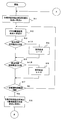
図2及び図3は、実施の形態の電子ペーパー表示部15の書き換え処理のフローチャートである。この書き換え処理は、電子ペーパー制御部13により実行される。
最初に、作業用保持始点及び終点を初期化する(S11)。ステップS11の初期化処理では、例えば、作業用保持始点と終点の初期値を原点(0,0)にする。
最初に、作業用保持始点及び終点を初期化する(S11)。ステップS11の初期化処理では、例えば、作業用保持始点と終点の初期値を原点(0,0)にする。
次に、VRAMの書き換え対象領域を監視し、書き換え対象領域の始点Aと終点Bを取得する(S12)。
最初に始点の判定を行うために、VRAMの書き換え対象領域の始点Aと作業用保持始点a(最初の判定では、初期値)を比較して、どちらの始点がより広い領域の始点かを判定する(S13)。
最初に始点の判定を行うために、VRAMの書き換え対象領域の始点Aと作業用保持始点a(最初の判定では、初期値)を比較して、どちらの始点がより広い領域の始点かを判定する(S13)。
VRAM16の書き換え対象領域の始点Aが、作業用保持始点aより広い領域の始点であると判定されたときには(S13、a<A)、ステップS14に進み、始点Aを作業用保持始点aとして設定する。
ステップS13の判定処理は、例えば、始点AがX軸上にあるときには、始点Aのx座標と作業用保持始点aのx座標を比較することで行う。また、始点AがY軸上にあるときには、始点Aのy座標と作業用保持始点aのy座標を比較することで行う。
他方、ステップS13において、VRAM16の書き換え対象領域の始点Aが、作業用保持始点aより狭い領域の始点であると判定されたときには、ステップS15に進み、次に終点の判定を行う。ステップS15においては、VRAM16の書き換え対象領域の終点Bと作業用保持終点bを比較して、どちらの終点がより広い領域の終点かを判定する。
VRAM16の書き換え対象領域の終点Bが、作業用保持終点bより広い領域の終点であると判定されたときには(S15、b<B)、ステップS16に進み、終点Bを作業用保持終点bとして設定する。
他方、ステップS15において、VRAM16の書き換え対象領域の終点Bが、作業用保持終点bより狭い領域の終点であると判定されたときには、ステップS17に進む。
上記のステップS15及びS16の処理により、VRAM16の書き換え対象領域の終点Bが、現在の作業用保持終点bより広い領域の終点と判定されたときには、その終点Bが新たな作業用保持終点bとしてメモリ等の記憶部に保存される。
上記のステップS15及びS16の処理により、VRAM16の書き換え対象領域の終点Bが、現在の作業用保持終点bより広い領域の終点と判定されたときには、その終点Bが新たな作業用保持終点bとしてメモリ等の記憶部に保存される。
ステップS17では、一定監視時間が経過したか否かを判定する。一定監視時間が経過していないときには(S17、NO)、ステップS12に戻り上述した処理を繰り返す。
一定監視時間が経過したときには(S17、YES)、ステップS18に進み、作業用保持始点a及び終点bから書き換え対象領域の始点aと終点bを決定する。ステップS18の次には、図3のステップS19(図3のB)に進む。
一定監視時間が経過したときには(S17、YES)、ステップS18に進み、作業用保持始点a及び終点bから書き換え対象領域の始点aと終点bを決定する。ステップS18の次には、図3のステップS19(図3のB)に進む。
次に、上記の前処理により書き換え対象領域の始点aと終点bが確定した後に、電子ペーパー表示部15の画面を書き換える場合の処理について、図3のフローチャートを参照して説明する。
ステップS19において、描画指示が全画面書き換えか否かを判定する。ステップS19において、描画指示が部分書き換えであると判定されたときには(S19、部分書き換え)、ステップS20に進み、次に部分書き換えを行う領域の始点aと終点bの間の座標が記憶部(例えば、メモリ)に存在するか否かを判定する。
上記のステップS20の処理では、例えば、次に部分書き換えを行う領域の始点と終点がX軸上にある場合には(これを横書き換えと呼ぶ)、書き換え対象領域の始点aのx座標と終点bのx座標の間の座標が記憶部に記憶されているか否かを判定する。また、部分書き換えを行う領域の始点aと終点bがY軸上にある場合には(これを縦書き換えと呼ぶ)、始点aのy座標と終点bのy座標の間の座標が記憶部に記憶されているか否かを判定する。
今回部分書き換えを行う領域の始点aと終点bとの間の座標が記憶部に存在する場合、つまり、それ以前に部分書き換えが行われていて、今回部分書き換えを行う領域に一部又は全部が含まれる領域が存在する場合には(S20、a、b間に座標が存在する)、ステップS21に進み、記憶部に格納されている該当する座標を削除する。これは、以前に部分書き換えを行った領域を含む広い領域の部分書き換えを新たに行うことで、その領域に含まれる部分領域の明度差が目立たなくなるからである。
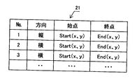
ここで、図4を参照して、記憶部に記憶されている始点と終点の座標について説明する。本実施の形態においては、部分書き換えを行った領域の始点と終点の座標を、図4に示すように記憶部(例えば、メモリ)のテーブル21に格納するようにしている。
テーブル21には、部分書き換えが行われた順に、部分書き換え領域の方向(縦又は横方向)を示すデータと、始点のx座標、y座標と、終点のx座標、y座標が格納されている。横方向とは、始点と終点がX軸上にある場合であり、縦方向とは、始点と終点がY軸上にある場合である。
図3のステップS20の判定処理では、次に部分書き換えを行う領域の始点aと終点bとの間の座標が記憶部、例えば、図4のテーブル21に登録されているか否かを判定している。
図3のステップS20の判定で、今回部分書き込みを行う領域の始点aと終点bとの間の座標が記憶部に存在しない場合には(S20、存在しない)、ステップS22に進み、今回部分書き込みを行う領域の始点aと終点bを記憶部に保存する。ステップS22の処理では、例えば、始点aと終点bの座標が、図4のテーブル21に格納される。
次に、記憶部に保持(記憶)してある部分書き換え領域の座標数が所定値N以上か否かを判定する(S23)。
記憶部に保持されている座標数が所定値N未満のときには(S23、保持座標数<N)、ステップS24に進み、始点aと終点bで指定される領域の部分書き換えを行う。
記憶部に保持されている座標数が所定値N未満のときには(S23、保持座標数<N)、ステップS24に進み、始点aと終点bで指定される領域の部分書き換えを行う。
記憶部に保持されている座標数が所定値N以上のときには(S23、N≦保持座標数)、ステップS25に進み、全画面の書き換えを行う。
全画面の書き換えを行うことにより、部分書き換えを行った領域と行っていない領域との明度差が無くなるので、記憶部の保持座標をクリアする(S26)。ステップS26の処理では、例えば、図4のテーブル21に格納されている複数の始点と終点の座標を削除する。
全画面の書き換えを行うことにより、部分書き換えを行った領域と行っていない領域との明度差が無くなるので、記憶部の保持座標をクリアする(S26)。ステップS26の処理では、例えば、図4のテーブル21に格納されている複数の始点と終点の座標を削除する。
ステップS19において、描画指示が全画面の書き換えと判定されたときには(S19、全書き換え)、ステップS27に進み、書き換え対象領域の始点aと終点bをメモリ等に一時記憶する。そして、始点a及び終点bで指定される全画面の書き換えを行う(S28)。
ステップS24又はS28において、書き換えが終了したなら、ステップS11(図32のA)に戻り上述した処理を繰り返す。
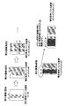
ここで、部分書き換え時の座標について、図5を参照して説明する。
ここで、部分書き換え時の座標について、図5を参照して説明する。
全面書き換え後の1回目の部分書き換えが横書き換えで、その書き換え領域の始点のx座標がx1,終点のx座標がx2であるとする。この場合、部分書き換え領域の始点のx座標x1と終点のx座標x2の間の座標は、記憶部には存在しないので、上述した書き換え処理により、始点のx座標x1と終点のx座標x2が記憶部(例えば、テーブル21)に保存される。
2回目の部分書き換えが横書き換えで、その書き換え領域の始点のx座標がx3、終点のx座標がx4であるとする。この場合、始点のx座標x3と終点のx座標x4との間の座標は記憶部には存在しないので、そのときの始点のx座標x3と終点のx座標x4は記憶部に保存される。この結果、記憶部には、x1とx2とx3とx4の4個のx座標が保存される。
3回目の部分書き換えが縦書き換えで、その書き換え領域の始点のy座標がy1、終点のy座標がy2であるとする。この場合、始点のy座標y1と終点のy座標y2の間の座標は記憶部には存在しないので、始点のy座標y1と終点のy座標y2が記憶部に保存される。この結果、記憶部には、x1、x2、x3、x4、y1、y2の6個の座標が保存される。
n回目の部分書き換えが横書き換えで、その書き換え領域の始点のx座標がx5、終点のx座標がx6であるとする。この場合、始点のx座標x5と終点のx座標x6との間の座標x3が記憶部に存在するので、その座標x3を記憶部から削除する。この結果、記憶部には、x2、x3、x4、x5、y1、y2の7個の座標が保存される。
n回目の部分書き換え領域の始点のx座標x5と終点のx座標x6の間の座標が記憶部に存在する場合には、n回目の部分書き換えを行うことで、座標x1を始点とする領域の一部(又は全部)も書き換えられることになる。その結果、n回目の部分書き換え領域と、その領域に含まれる座標x1を始点とする領域の一部(又は全部)の領域の明度差は無視できることになるので、座標x1を記憶部から座標を削除する。なお、削除する座標は、1個に限らず、その間に複数の座標が存在する場合には、それらの座標を削除する。
上述した実施の形態は、部分書き換えを行った領域の始点及び終点の座標を記憶部に保存しておき、次に部分書き換えを行う領域の始点と終点の間の座標が記憶部に存在するか否かを判定し、座標が存在する場合にはその座標を削除する。そして、記憶部に記憶されている座標数が所定値N以上か否かを判定し、座標数が所定値N以上となった時点で全画面の書き換えを行う。これにより、部分書き換えが行われた領域と他の領域との明度差が目立つのを抑えることができる。
実施の形態は、部分書き換え領域が、それ以前の部分書き換え領域の一部(又は全部)を含む場合には、その領域の始点又は終点(始点及び終点)の座標を削除しているので、部分書き換え回数が一定値に達したときに全面書き換えを行う方法に比べて、全面書き換えの回数を減らすことができる。
Claims (4)
- メモリ性を有する液晶表示部と、
部分書き換えを行った領域の始点と終点の座標を記憶する記憶手段と、
次に部分書き換えを行う領域の始点と終点の間の座標が前記記憶手段に存在するか否かを判定する座標判定手段と、
前記座標判定手段により、前記記憶手段に該当する座標が存在すると判定された場合に、前記記憶手段から該当する座標を削除すると共に、次に部分書き換えを行う領域の始点と終点の座標を前記記憶手段に保存する座標管理手段と、
前記記憶手段に記憶されている座標数が所定値に達したか否かを判定する座標数判定手段と、
前記座標数判定手段により前記記憶手段に記憶されている座標数が前記所定値に達したと判定されたときに、前記液晶表示部の全面書き換えを行う表示制御手段とを備える電子ペーパー装置。 - 前記記憶手段は、部分書き換えを行った領域のX軸方向の始点のx座標と終点のx座標又はY軸方向の始点のy座標と終点のy座標を記憶し、
前記座標判定手段は、次に部分書き換えを行う領域の前記始点のx座標又はy座標と前記終点のx座標又はy座標の間の座標が、前記記憶手段に記憶されているか否かを判定する請求項1記載の電子ペーパー装置。 - メモリ性の液晶表示部を有する電子ペーパー装置の表示制御方法であって、
部分書き換えを行った領域の始点と終点の座標を記憶手段に記憶し、
次に部分書き換えを行う領域の始点と終点の間の座標が前記記憶手段に存在するか否かを判定し、
次に部分書き換えを行う領域の始点と終点の座標の間の座標が前記記憶手段に存在する場合には、前記記憶手段から該当する座標を削除し、次に部分書き換えを行う領域の前記始点と前記終点の座標を前記記憶手段に保存し、
前記記憶手段に記憶されている座標数が所定値に達したか否かを判定し、
前記座標数が所定値に達したときには、前記液晶表示部の全面書き換えを行う電子ペーパー装置の表示制御方法。 - 部分書き換えを行った領域のX軸方向の始点のx座標と終点のx座標又はY軸方向の始点のy座標と終点のy座標を前記記憶手段に記憶し、
次に部分書き換えを行う領域の前記始点のx座標又はy座標と前記終点のx座標又はy座標の間の座標が、前記記憶手段に記憶されているか否かを判定する請求項3記載の電子ペーパー装置の表示制御方法。
Priority Applications (3)
| Application Number | Priority Date | Filing Date | Title |
|---|---|---|---|
| JP2011501348A JP5276160B2 (ja) | 2009-02-26 | 2009-02-26 | 電子ペーパー装置及び電子ペーパーの表示制御方法 |
| PCT/JP2009/000868 WO2010097836A1 (ja) | 2009-02-26 | 2009-02-26 | 電子ペーパー装置及び電子ペーパーの表示制御方法 |
| TW099105009A TW201037692A (en) | 2009-02-26 | 2010-02-22 | Electronic paper device and display control method for electronic paper |
Applications Claiming Priority (1)
| Application Number | Priority Date | Filing Date | Title |
|---|---|---|---|
| PCT/JP2009/000868 WO2010097836A1 (ja) | 2009-02-26 | 2009-02-26 | 電子ペーパー装置及び電子ペーパーの表示制御方法 |
Publications (1)
| Publication Number | Publication Date |
|---|---|
| WO2010097836A1 true WO2010097836A1 (ja) | 2010-09-02 |
Family
ID=42665066
Family Applications (1)
| Application Number | Title | Priority Date | Filing Date |
|---|---|---|---|
| PCT/JP2009/000868 Ceased WO2010097836A1 (ja) | 2009-02-26 | 2009-02-26 | 電子ペーパー装置及び電子ペーパーの表示制御方法 |
Country Status (3)
| Country | Link |
|---|---|
| JP (1) | JP5276160B2 (ja) |
| TW (1) | TW201037692A (ja) |
| WO (1) | WO2010097836A1 (ja) |
Cited By (2)
| Publication number | Priority date | Publication date | Assignee | Title |
|---|---|---|---|---|
| CN112703555A (zh) * | 2018-02-26 | 2021-04-23 | 先端科技株式会社 | 电子显示装置及电子显示方法 |
| WO2025213351A1 (zh) * | 2024-04-09 | 2025-10-16 | 虹彩光电股份有限公司 | 电子纸显示装置及其更新方法 |
Citations (3)
| Publication number | Priority date | Publication date | Assignee | Title |
|---|---|---|---|---|
| JPH03109524A (ja) * | 1989-06-26 | 1991-05-09 | Matsushita Electric Ind Co Ltd | 表示パネルの駆動方法と表示装置 |
| JPH05323281A (ja) * | 1992-05-19 | 1993-12-07 | Canon Inc | 表示制御装置及び方法 |
| WO2008038358A1 (en) * | 2006-09-28 | 2008-04-03 | Fujitsu Limited | Display element and display element image rewrite method, electronic paper using the display element, and electronic terminal |
-
2009
- 2009-02-26 JP JP2011501348A patent/JP5276160B2/ja active Active
- 2009-02-26 WO PCT/JP2009/000868 patent/WO2010097836A1/ja not_active Ceased
-
2010
- 2010-02-22 TW TW099105009A patent/TW201037692A/zh unknown
Patent Citations (3)
| Publication number | Priority date | Publication date | Assignee | Title |
|---|---|---|---|---|
| JPH03109524A (ja) * | 1989-06-26 | 1991-05-09 | Matsushita Electric Ind Co Ltd | 表示パネルの駆動方法と表示装置 |
| JPH05323281A (ja) * | 1992-05-19 | 1993-12-07 | Canon Inc | 表示制御装置及び方法 |
| WO2008038358A1 (en) * | 2006-09-28 | 2008-04-03 | Fujitsu Limited | Display element and display element image rewrite method, electronic paper using the display element, and electronic terminal |
Cited By (2)
| Publication number | Priority date | Publication date | Assignee | Title |
|---|---|---|---|---|
| CN112703555A (zh) * | 2018-02-26 | 2021-04-23 | 先端科技株式会社 | 电子显示装置及电子显示方法 |
| WO2025213351A1 (zh) * | 2024-04-09 | 2025-10-16 | 虹彩光电股份有限公司 | 电子纸显示装置及其更新方法 |
Also Published As
| Publication number | Publication date |
|---|---|
| JPWO2010097836A1 (ja) | 2012-08-30 |
| JP5276160B2 (ja) | 2013-08-28 |
| TW201037692A (en) | 2010-10-16 |
Similar Documents
| Publication | Publication Date | Title |
|---|---|---|
| US10395587B2 (en) | Method and apparatus for establishing luminance compensation model, method and apparatus for compensating for luminance of display screen, and display device | |
| US5583534A (en) | Method and apparatus for driving liquid crystal display having memory effect | |
| TWI439992B (zh) | 電光顯示器之顯示更新控制 | |
| KR102417633B1 (ko) | 디스플레이에 표시된 콘텐트의 표시 위치에 기반하여, 콘텐트를 수신할 수 있는 상태에 대응하는 신호의 출력 타이밍을 제어하기 위한 전자 장치 및 방법 | |
| JP2012155317A (ja) | 電子ディスプレイのための時間的および空間的にオーバーラップした更新を処理するための方法および装置 | |
| CN104867449A (zh) | 显示器的像素补偿方法及显示器 | |
| JP2011237709A (ja) | 表示装置の制御方法、表示装置、及び表示装置の制御装置 | |
| JP2009204813A (ja) | 画像書き換え制御装置および情報表示装置 | |
| JP5786292B2 (ja) | 制御装置、表示装置及び表示装置の制御方法 | |
| JP2009204814A (ja) | 画像書き換え制御装置および情報表示装置 | |
| US11488552B2 (en) | Display device and method for controlling same | |
| JP5276160B2 (ja) | 電子ペーパー装置及び電子ペーパーの表示制御方法 | |
| JP4267299B2 (ja) | 表示制御装置、画像表示装置および制御データ転送方法 | |
| JP2005140959A (ja) | 表示装置及びこれを用いた携帯機器 | |
| JP4599049B2 (ja) | 表示装置及びこれを用いた携帯機器 | |
| JP2006154750A (ja) | 液晶表示装置及びその駆動方法 | |
| JP2013109291A5 (ja) | 表示装置、表示装置の制御方法及び制御装置 | |
| JP2008111930A (ja) | 情報表示装置および駆動方法 | |
| US20060017738A1 (en) | System and method for detecting memory writes to initiate image data transfers | |
| JP5076934B2 (ja) | 情報表示装置 | |
| JP5268146B2 (ja) | 表示ムラの再現方法及び表示装置 | |
| CN116935812B (zh) | 液晶显示面板开启电压的确定方法、装置及电子设备 | |
| JP2006072351A (ja) | 画像データ転送用転送矩形を連続的にトレースするシステムおよび方法 | |
| US20050259105A1 (en) | System and method for detecting memory location modifications to initiate image data transfers | |
| JP2005140957A (ja) | 表示装置及びこれを用いた携帯機器 |
Legal Events
| Date | Code | Title | Description |
|---|---|---|---|
| 121 | Ep: the epo has been informed by wipo that ep was designated in this application |
Ref document number: 09840691 Country of ref document: EP Kind code of ref document: A1 |
|
| ENP | Entry into the national phase |
Ref document number: 2011501348 Country of ref document: JP Kind code of ref document: A |
|
| NENP | Non-entry into the national phase |
Ref country code: DE |
|
| 122 | Ep: pct application non-entry in european phase |
Ref document number: 09840691 Country of ref document: EP Kind code of ref document: A1 |