WO2010095708A1 - 伝送遅延時間測定方法 - Google Patents
伝送遅延時間測定方法 Download PDFInfo
- Publication number
- WO2010095708A1 WO2010095708A1 PCT/JP2010/052522 JP2010052522W WO2010095708A1 WO 2010095708 A1 WO2010095708 A1 WO 2010095708A1 JP 2010052522 W JP2010052522 W JP 2010052522W WO 2010095708 A1 WO2010095708 A1 WO 2010095708A1
- Authority
- WO
- WIPO (PCT)
- Prior art keywords
- communication terminal
- delay time
- transmission delay
- time
- packet
- Prior art date
- Legal status (The legal status is an assumption and is not a legal conclusion. Google has not performed a legal analysis and makes no representation as to the accuracy of the status listed.)
- Ceased
Links
Images



Classifications
-
- H—ELECTRICITY
- H04—ELECTRIC COMMUNICATION TECHNIQUE
- H04L—TRANSMISSION OF DIGITAL INFORMATION, e.g. TELEGRAPHIC COMMUNICATION
- H04L43/00—Arrangements for monitoring or testing data switching networks
- H04L43/08—Monitoring or testing based on specific metrics, e.g. QoS, energy consumption or environmental parameters
- H04L43/0852—Delays
- H04L43/0858—One way delays
-
- H—ELECTRICITY
- H04—ELECTRIC COMMUNICATION TECHNIQUE
- H04L—TRANSMISSION OF DIGITAL INFORMATION, e.g. TELEGRAPHIC COMMUNICATION
- H04L43/00—Arrangements for monitoring or testing data switching networks
- H04L43/04—Processing captured monitoring data, e.g. for logfile generation
- H04L43/045—Processing captured monitoring data, e.g. for logfile generation for graphical visualisation of monitoring data
Definitions
- the present invention relates to a transmission delay time measuring method for measuring a transmission delay time of a communication network, particularly a minimum transmission delay time.
- the minimum transmission delay time of the communication network is the basic data for management of communication services sensitive to transmission delay and creation of virtual maps on the communication network.
- the transmission delay time has been acquired by transmitting a packet signal from one communication terminal and measuring the elapsed time until the other communication terminal receives the packet signal.
- a transmitting device transmits a signal including time information to a communication network
- a receiving device detects time information from the received signal and measures a transmission delay time from a difference from the time information possessed by the receiving device.
- Patent Document 1 For example, refer to Patent Document 1.
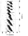
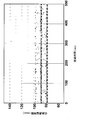
- FIG. 1 is an example of measuring the transmission delay time in a wireless access section of a cellular phone network.
- packet signals are regularly transmitted to the reception side via the mobile phone network, and the transmission delay time from when the transmission side transmits the packet signal until the reception side receives the packet signal is measured. It is a result.
- the transmission interval is largely dependent on the frame period because the time interval for transmitting the packet signal on the transmitting side and the frame period used in the radio access section of the cellular phone network are asynchronous and the frame period is quite long. Will do. As shown in FIG. 1, when the transmission delay time varies greatly in the relative time position with respect to the frame, even if the minimum transmission delay time is calculated from the measured transmission delay time, the reliability of the minimum transmission delay time is deteriorated.
- an object of the present invention is to provide a transmission delay time measuring method capable of calculating a reliable minimum transmission delay time.
- the transmission delay time measuring method of the present invention measures a transmission delay time until a large number of packet signals with random time intervals are transmitted and received via a target communication network. It was.
- the transmission delay time measuring method of the present invention measures a transmission delay time from a first communication terminal connected to a communication network using a periodic fixed-length frame to a second communication terminal.
- a transmission delay time measuring method wherein a plurality of packet signals with random time intervals are transmitted from the first communication terminal to the second communication terminal via the communication network, and the plurality of packets Measure the transmission delay time from the first communication terminal to the second communication terminal based on the time from when the first communication terminal transmits the signal to when the second communication terminal receives the signal It is characterized by doing.
- the transmission delay time can be measured without depending on the frame period even if the frame length used by the target communication network is long.
- the transmission delay time measuring method of the present invention is characterized in that the first communication terminal and the second communication terminal are the same.
- the measurement system can be configured simply.
- the transmission delay time measuring method of the present invention is a transmission delay time measuring method for measuring a transmission delay time from a first communication terminal connected to a communication network using a periodic fixed-length frame to a second communication terminal.
- the first communication terminal transmits a plurality of packet signals with random time intervals to the second communication terminal via the communication network, and each time the packet signal is received, A packet signal with a random time interval is transmitted from the second communication terminal to the first communication terminal via the communication network, and the plurality of packet signals are transmitted by the first communication terminal.
- measuring the transmission delay time from the first communication terminal to the second communication terminal based on the time until the first communication terminal receives the data again.
- the transmission delay time can be measured without depending on the frame period even if the frame length used by the target communication network is long.
- the transmission delay time measuring method of the present invention is a transmission delay time measuring method for measuring a transmission delay time from a first communication terminal connected to a communication network using a periodic fixed-length frame to a second communication terminal.
- the first communication terminal transmits a plurality of packet signals with random time intervals to the second communication terminal via the communication network, and each time the packet signal is received, From the second communication terminal via the communication network to the first communication terminal, receive and transmit a packet signal after a lapse of a fixed time, and the first communication terminal receives the plurality of packet signals.
- a transmission delay time from the first communication terminal to the second communication terminal is measured based on a time from when the first communication terminal receives the signal to when the first communication terminal receives again. .
- the transmission delay time can be measured without depending on the frame period even if the frame length used by the target communication network is long.
- the transmission delay time measuring method of the present invention is characterized in that the first communication terminal and the second communication terminal have different frame lengths and are connected to asynchronous communication networks.
- the above-described measuring method can achieve the object.
- the transmission delay time measuring method of the present invention is characterized in that the plurality of packet signals with random time intervals are generated by giving random fluctuation times to a fixed period.
- the packet signal when a packet signal is randomly generated, the packet signal can be transmitted at random time intervals.
- the transmission delay time measuring method of the present invention is characterized in that the plurality of packet signals with random time intervals are generated with a constant period and delayed by a random fluctuation time.
- the packet signal when a random delay is given to a packet signal, the packet signal can be transmitted at random time intervals.
- the transmission delay time measuring method of the present invention is characterized in that a maximum time interval of a plurality of packet signals with random time intervals is equal to or longer than a time corresponding to a frame length used by the communication network.
- a random time interval of the packet signal transmitted by the second communication terminal can be maintained.
- the outer edge on the lower side of the distribution is set to the minimum value of the transmission delay time, and the center of the transmission delay time is densely distributed. It is calculated as the most frequently occurring value.
- the transmission delay time measuring method of the present invention even if the frame length used by the target communication network is a fixed length, the transmission delay time can be measured without depending on the frame period.
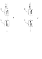
- the transmission delay time measurement system which measures the one-way transmission delay time concerning this embodiment at a near end is shown.
- the transmission delay time measuring system which measures the one-way transmission delay time based on this embodiment in a far end is shown.
- (A) And (b) shows the structural example of a packet transmission circuit.
- the transmission delay time measurement system which measures the round trip transmission delay time which concerns on this embodiment at a near end is shown.
- 1 shows a transmission delay time measurement system for measuring a round trip transmission delay time at a far end according to the present embodiment.
- (A) And (b) shows the structural example of a packet transmission circuit. An example of measured transmission delay time is shown. An example of measured transmission delay time is shown.
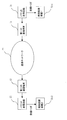
- FIG. 1 A transmission delay time measurement system according to the present embodiment is shown in FIG.
- 11 is a first communication terminal
- 12 is a second communication terminal
- 21 is a packet transmission circuit
- 22 is a packet reception circuit
- 31 is a delay time measurement circuit
- 51 is a communication whose transmission delay time is to be measured. It is a network.
- the communication network 51 transmits a packet using a periodic fixed-length frame.
- the packet transmission circuit 21 generates a plurality of packet signals with random time intervals and outputs them to the first communication terminal 11.
- the first communication terminal 11 to which the packet signal is input transmits the packet signal to the second communication terminal 12 via the communication network 51.
- the packet transmission circuit 21 outputs a transmission trigger to the delay time measurement circuit 31 simultaneously with outputting the packet signal.
- the second communication terminal 12 receives the packet signal that has passed through the communication network and outputs it to the packet receiving circuit 22.
- the packet reception circuit 22 decodes the packet signal and outputs a reception trigger to the delay time measurement circuit 31.
- the delay time measurement circuit 31 transmits the time from when the transmission trigger is input to when the reception trigger is input as the time from when the first communication terminal 11 transmits until the second communication terminal 12 receives it. Measure the delay time. If the delay in the first communication terminal 11, the second communication terminal 12, the packet transmission circuit 21 or the packet reception circuit 22 is not negligible compared to the transmission delay time, these delays are measured in advance, The measured transmission delay time may be calibrated.
- the first communication terminal 11 transmits a packet signal
- the communication network 51 uses a fixed-length frame
- a transmission delay time depending on the frame occurs. If the packet signal is transmitted around the end of the frame, the waiting time is short, but if the packet signal is transmitted around the beginning of the frame, the waiting time becomes long.
- the transmission delay time becomes regular depending on the frame period of the communication network 51. However, when the first communication terminal 11 transmits a plurality of packet signals with random time intervals, the transmission delay time of each packet signal becomes random.
- the first communication terminal 11 and the second communication terminal 12 may be the same terminal.
- the packet signal directed to itself is received by itself through the communication network 51. Since the packet signal is received by itself, the transmission delay time can be easily measured.
- FIG. 32-1 is the time recording device 1
- 32-2 is the time recording device 2.
- the transmission delay time of the packet signal uses the transmission trigger of the packet transmission circuit 21, records the time when the packet signal is output by the time recording device 1, and uses the reception trigger of the packet reception circuit 22.
- the time recording device 2 records the time when the packet signal is input. If the times of the time recording device 1 and the time recording device 2 are calibrated, the transmission delay time of the packet signal can be measured from the time difference between the time recording device 1 and the time recording device 2. Even in this case, when the first communication terminal 11 transmits a plurality of packet signals with random time intervals, the transmission delay time of each packet signal becomes random.
- the first communication terminal 11 and the second communication terminal 12 have different frame lengths, and may be connected to an asynchronous communication network. This is because when the first communication terminal 11 transmits a plurality of packet signals with random time intervals, the transmission delay time of each packet signal becomes random.
- the maximum time interval of a plurality of packet signals with random time intervals is preferably equal to or longer than the time corresponding to the frame length used by the communication network 51. This is because if the maximum time interval between a plurality of random packet signals is shorter than the time corresponding to the frame length used by the communication network 51, the distribution of the transmission delay time is affected by the frame period.
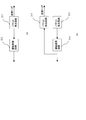
- FIG. 4 A configuration example of the packet transmission circuit is shown in FIG.
- 211 and 213 are packet generation circuits
- 212 and 214 are delay variation circuits
- 215 is a packet detection circuit.
- the packet generation circuit 211 generates a packet signal and outputs it to the delay variation circuit 212.
- the delay variation circuit 212 adds a delay variation to the input packet signal and outputs it. Since this packet generation circuit 211 knows in advance the delay amount provided by the delay variation circuit 212, the packet generation circuit 211 outputs a transmission trigger at the timing when the delay variation circuit 212 outputs the packet signal.
- the packet generation circuit 213 generates a packet signal and outputs it to the delay variation circuit 214.
- the delay variation circuit 214 gives a delay variation to the input packet signal and outputs it.
- the packet detection circuit 215 detects the packet signal from the delay variation circuit 214 and outputs a transmission trigger.
- the packet detection circuit 215 outputs a transmission trigger by detecting the packet signal without knowing the delay amount given by the delay variation circuit 212.
- the packet generation circuits 211 and 213 may generate a plurality of packet signals at random time intervals with respect to a certain period, and randomize the packet signal time intervals. Further, a plurality of packet signals may be generated at a constant period and delayed by a random time, so that the time interval of the packet signals is random. Packet signals can be transmitted at random time intervals.
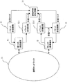
- FIG. 5 shows a transmission delay time measurement system according to this embodiment.
- 11 is a first communication terminal
- 12 is a second communication terminal
- 21 and 23 are packet transmission circuits
- 22-1 and 22-2 are packet reception circuits
- 33 is a delay time measurement circuit
- 51 is a transmission.
- This is a communication network whose delay time is to be measured.
- the communication network 51 transmits a packet using a periodic fixed-length frame.
- the packet transmission circuit 21 generates a plurality of packet signals with random time intervals and outputs them to the first communication terminal 11.
- the first communication terminal 11 to which the packet signal is input transmits the packet signal to the second communication terminal 12 via the communication network 51.
- the packet transmission circuit 21 outputs a transmission trigger to the delay time measurement circuit 33 simultaneously with outputting the packet signal.
- the second communication terminal 12 receives the packet signal transmitted via the communication network and outputs it to the packet receiving circuit 22-2.
- the packet reception circuit 22-2 decodes the packet signal and outputs a reception trigger to the delay time measurement circuit 33.
- the packet reception circuit 22-2 also outputs a reception trigger to the packet transmission circuit 23.
- the packet transmission circuit 23 to which the reception trigger is input generates a plurality of packet signals with random time intervals and outputs them to the second communication terminal 12.
- the second communication terminal 12 to which the packet signal is input transmits the packet signal toward the first communication terminal 11 via the communication network 51.
- the packet transmission circuit 23 outputs a transmission trigger to the delay time measurement circuit 33 simultaneously with outputting the packet signal.
- the first communication terminal 11 receives the packet signal that has passed through the communication network, and outputs the packet signal to the packet receiving circuit 22-1.
- the packet reception circuit 22-1 decodes the packet signal and outputs a reception trigger to the delay time measurement circuit 33.
- the delay time measurement circuit 33 transmits the time from the transmission trigger output from the packet transmission circuit 21 to the reception trigger output from the packet reception circuit 22-2 after the first communication terminal 11 transmits.
- the second communication terminal 12 transmits the time from the transmission trigger output from the packet transmission circuit 23 to the reception trigger output from the packet reception circuit 22-1 until the first communication terminal 11
- the transmission delay time is measured as the time until reception. The sum of the respective transmission delay times becomes the round trip transmission delay time. If delays in the first communication terminal 11, the second communication terminal 12, the packet transmission circuits 21 and 23 or the packet reception circuits 22-1 and 22-2 are not negligible compared to the transmission delay time, It is sufficient to calibrate the measured transmission delay time.
- the transmission delay time becomes regular depending on the frame period of the communication network.
- the transmission delay time of each packet signal becomes random.
- the first communication terminal 11 When measuring the round trip transmission delay time at the near end, not only the first communication terminal 11 transmits a plurality of packet signals with random time intervals, but also the second communication terminal 12 has a random time interval. It is necessary to transmit a plurality of packet signals.
- the second communication terminal 12 When the second communication terminal 12 periodically transmits a packet signal, the transmission delay time greatly varies in the relative time position with the frame used by the communication network, so the minimum transmission delay time is calculated from the measured transmission delay time. Even so, the reliability of the minimum transmission delay time is deteriorated.
- the second communication terminal 12 may transmit a packet signal having a random time interval, or may receive the packet signal and transmit the packet signal after a fixed time has elapsed. That is, the time interval at which the packet reception circuit 22-2 outputs the reception trigger is random.
- the packet transmission circuit 23 outputs a packet signal after a fixed time has elapsed after the reception trigger output from the packet reception circuit 22-2 is input
- the second communication terminal outputs a packet signal with a random time interval. Will be sent.
- the transmission delay time of the packet signal includes not only the time from the transmission trigger output from the packet transmission circuit 21 to the reception trigger output from the packet reception circuit 22-1 but also the reception trigger output from the packet reception circuit 22-2. It is necessary to calculate in consideration of the time from the input to the packet transmission circuit 23 until the packet transmission circuit 23 outputs the packet signal.
- the round-trip transmission delay time is measured at the far end, not only the first communication terminal 11 transmits a plurality of packet signals with random time intervals, but also the second communication terminal 12 has a random time interval. Multiple packet signals need to be transmitted.
- the second communication terminal 12 periodically transmits a packet signal, the transmission delay time greatly varies in the relative time position with the frame used by the communication network, so the minimum transmission delay time is calculated from the measured transmission delay time. Even so, the reliability of the minimum transmission delay time is deteriorated.
- the second communication terminal 12 may transmit a packet signal having a random time interval, or may receive the packet signal and transmit the packet signal after a fixed time has elapsed. That is, the time interval at which the packet reception circuit 22-2 outputs the reception trigger is random.
- the packet transmission circuit 23 outputs a packet signal after a fixed time has elapsed after the reception trigger output from the packet reception circuit 22-2 is input
- the second communication terminal outputs a packet signal with a random time interval. Will be sent.
- FIG. 7 A configuration example of the packet transmission circuit is shown in FIG.
- 216 is a packet generation circuit
- 217 is a delay variation circuit
- 218 is a fixed delay circuit.
- the packet generation circuit 216 when a reception trigger is input, the packet generation circuit 216 generates a packet signal and outputs the packet signal to the delay variation circuit 217.
- the delay variation circuit 217 gives a delay variation to the input packet signal and outputs it.
- the packet transmission circuit transmits a plurality of packet signals with random time intervals without periodically outputting the packet signals.
- the packet generation circuit 216 when the reception trigger is input, the packet generation circuit 216 generates a packet signal and outputs the packet signal to the fixed delay circuit 218.
- the fixed delay circuit 218 gives a fixed delay to the input packet signal and outputs it.
- the packet transmission circuit transmits a plurality of packet signals with random time intervals without periodically outputting the packet signals. This is because if the fixed time has elapsed, the randomness of the packet signal transmission time interval is maintained.
- the first communication terminal 11 and the second communication terminal 12 have different frame lengths, and may be connected to an asynchronous communication network. This is because when the first communication terminal 11 transmits a plurality of packet signals with random time intervals, the transmission delay time of each packet signal becomes random.
- the maximum time interval of a plurality of packet signals with random time intervals be equal to or longer than the time corresponding to the frame length used by the communication network 51. This is because if the maximum time interval between a plurality of random packet signals is shorter than the time corresponding to the frame length used by the communication network 51, the distribution of the transmission delay time is affected by the frame period.
- FIG. 8 shows an example of the transmission delay time measured by the transmission delay time measurement system shown in FIG.
- the lower outer edge of the transmission delay time with respect to the elapsed time is set as the minimum value of the transmission delay time.
- the transmission delay time becomes sufficiently random, and as a result, it is easy to calculate the minimum value of the transmission delay time from the measured transmission delay time distribution. Become.
- FIG. 9 shows an example of another transmission delay time measured by the transmission delay time measurement system shown in FIG.
- the lower outer edge of the distribution of the transmission delay time with respect to the elapsed time is the minimum value of the transmission delay time
- the transmission delay time that is densely distributed with respect to the elapsed time is the most frequent value.
- the transmission delay time becomes sufficiently random, and as a result, it is easy to calculate the minimum value or the most frequent value from the measured transmission delay time distribution. Become.
- the transmission delay time measuring method of the present invention can be used for management of communication services sensitive to transmission delay and creation of virtual maps on a communication network.
- first communication terminal 12 second communication terminal 21, 23: packet transmission circuits 22, 22-1, 22-2: packet reception circuits 211, 213, 216: packet generation circuits 212, 214, 217 are delayed Fluctuation circuit 215: Packet detection circuit 218: Fixed delay circuits 31, 33, 34: Delay time measurement circuits 32-1, 32-2: Time recording device 51: Communication network
Landscapes
- Engineering & Computer Science (AREA)
- Environmental & Geological Engineering (AREA)
- Computer Networks & Wireless Communication (AREA)
- Signal Processing (AREA)
- Data Exchanges In Wide-Area Networks (AREA)
- Mobile Radio Communication Systems (AREA)
Abstract
本願発明は、信頼性のよい最小伝送遅延時間を算出することのできる伝送遅延時間測定方法を提供することを目的とする。本願発明の伝送遅延時間測定方法は、周期的な固定長のフレームを利用する通信ネットワークに接続された第一の通信端末から第二の通信端末までの伝送遅延時間を測定する伝送遅延時間測定方法であって、前記第一の通信端末から前記通信ネットワークを経由して前記第二の通信端末に向けて、時間間隔がランダムな複数のパケット信号を送信し、前記複数のパケット信号を、前記第一の通信端末が送信してから前記第二の通信端末が受信するまでの時間に基づいて、前記第一の通信端末から前記第二の通信端末までの伝送遅延時間を測定する。
Description
本発明は、通信ネットワークの伝送遅延時間、特に最小伝送遅延時間を測定する伝送遅延時間測定方法に関する。
伝送遅延に敏感な通信サービスの管理や、通信ネットワーク上で仮想地図の作成には、通信ネットワークの最小伝送遅延時間が基本データとなる。従来、伝送遅延時間は、一つの通信端末からパケット信号を送信し、他の通信端末が受信するまでの経過時間を測定することによって取得していた。例えば、送信装置では、時刻情報を含む信号を通信ネットワークに送信し、受信装置では、受信した信号から時刻情報を検出して、受信装置の有する時刻情報との差分から伝送遅延時間を測定していた(例えば、特許文献1参照。)。
しかし、携帯電話ネットワークの無線アクセス区間では、他のネットワークよりもかなり長いフレームを利用しているため、携帯電話ネットワークの伝送遅延時間は受信するパケット信号のタイミングとフレームとの相対時間位置で大きく変動することになる。図1は、携帯電話ネットワークの無線アクセス区間での伝送遅延時間を測定した例である。送信側では、携帯電話ネットワークを経由して受信側に向けて規則的にパケット信号を送信し、送信側がパケット信号を送信してから受信側でパケット信号を受信するまでの伝送遅延時間を測定した結果である。
送信側のパケット信号を送信する時間間隔と携帯電話ネットワークの無線アクセス区間に利用しているフレーム周期が非同期であり、かつ、当該フレーム周期がかなり長いため、伝送遅延時間は当該フレーム周期に大きく依存することになる。図1に示すように、伝送遅延時間が当該フレームとの相対時間位置で大きく変動すると、測定した伝送遅延時間から最小伝送遅延時間を算出しても、最小伝送遅延時間の信頼性が悪くなる。
前記課題を解決するために、本発明は、信頼性のよい最小伝送遅延時間を算出することのできる伝送遅延時間測定方法を提供することを目的とする。
上記目的を達成するために、本願発明の伝送遅延時間測定方法は、時間間隔がランダムなパケット信号を多数送信し、対象とする通信ネットワークを経由して受信するまでの伝送遅延時間を測定することとした。
具体的には、本願発明の伝送遅延時間測定方法は、周期的な固定長のフレームを利用する通信ネットワークに接続された第一の通信端末から第二の通信端末までの伝送遅延時間を測定する伝送遅延時間測定方法であって、前記第一の通信端末から前記通信ネットワークを経由して前記第二の通信端末に向けて、時間間隔がランダムな複数のパケット信号を送信し、前記複数のパケット信号を、前記第一の通信端末が送信してから前記第二の通信端末が受信するまでの時間に基づいて、前記第一の通信端末から前記第二の通信端末までの伝送遅延時間を測定することを特徴とする。
本願発明の伝送遅延時間測定方法によれば、対象とする通信ネットワークの利用するフレーム長が長くても、フレーム周期に依存することなく伝送遅延時間を測定することができる。
本願発明の伝送遅延時間測定方法は、前記第一の通信端末と前記第二の通信端末が同一であることを特徴とする。
本願発明の伝送遅延時間測定方法によれば、同一の通信端末で測定できれば、測定系を簡易な構成とすることができる。
本願発明の伝送遅延時間測定方法は、周期的な固定長のフレームを利用する通信ネットワークに接続された第一の通信端末から第二の通信端末までの伝送遅延時間を測定する伝送遅延時間測定方法であって、前記第一の通信端末から前記通信ネットワークを経由して前記第二の通信端末に向けて、時間間隔がランダムな複数のパケット信号を送信し、前記パケット信号を受信するごとに前記第二の通信端末から前記通信ネットワークを経由して前記第一の通信端末に向けて、時間間隔がランダムなパケット信号を送信し、前記複数のパケット信号を、前記第一の通信端末が送信してから再び前記第一の通信端末が受信するまでの時間に基づいて、前記第一の通信端末から前記第二の通信端末までの伝送遅延時間を測定することを特徴とする。
本願発明の伝送遅延時間測定方法によれば、対象とする通信ネットワークの利用するフレーム長が長くても、フレーム周期に依存することなく伝送遅延時間を測定することができる。
本願発明の伝送遅延時間測定方法は、周期的な固定長のフレームを利用する通信ネットワークに接続された第一の通信端末から第二の通信端末までの伝送遅延時間を測定する伝送遅延時間測定方法であって、前記第一の通信端末から前記通信ネットワークを経由して前記第二の通信端末に向けて、時間間隔がランダムな複数のパケット信号を送信し、前記パケット信号を受信するごとに前記第二の通信端末から前記通信ネットワークを経由して前記第一の通信端末に向けて、受信して固定時間経過後パケット信号を送信し、前記複数のパケット信号を、前記第一の通信端末が送信してから再び前記第一の通信端末が受信するまでの時間に基づいて、前記第一の通信端末から前記第二の通信端末までの伝送遅延時間を測定することを特徴とする。
本願発明の伝送遅延時間測定方法によれば、対象とする通信ネットワークの利用するフレーム長が長くても、フレーム周期に依存することなく伝送遅延時間を測定することができる。
本願発明の伝送遅延時間測定方法は、前記第一の通信端末及び前記第二の通信端末はそれぞれフレーム長が異なり、互いに非同期の通信ネットワークに接続されていることを特徴とする。
本願発明の伝送遅延時間測定方法によれば、互いに非同期の通信ネットワークであっても、前述した測定方法であれば、目的を達成することができる。
本願発明の伝送遅延時間測定方法は、前記時間間隔がランダムな複数のパケット信号は、一定周期に対してランダムな変動時間を付与して生成することを特徴とする。
本願発明の伝送遅延時間測定方法によれば、パケット信号をランダムに生成すると、パケット信号をランダムな時間間隔で送信することができる。
本願発明の伝送遅延時間測定方法は、前記時間間隔がランダムな複数のパケット信号は、一定周期で発生させ、ランダムな変動時間だけ遅延させて生成することを特徴とする
本願発明の伝送遅延時間測定方法によれば、パケット信号にランダムな遅延を付与すると、パケット信号をランダムな時間間隔で送信することができる。
本願発明の伝送遅延時間測定方法は、前記時間間隔がランダムな複数のパケット信号の最大時間間隔が、前記通信ネットワークの利用するフレーム長に相当する時間以上であることを特徴とする
本願発明の伝送遅延時間測定方法によれば、第二の通信端末の送信するパケット信号のランダムな時間間隔を維持することができる。
本願発明の伝送遅延時間測定方法は、測定した経過時間に対する前記伝送遅延時間の分布から、分布の下側の外縁を伝送遅延時間の最小値とし、密に分布している中心を伝送遅延時間の最頻出値として算出することを特徴とする。
なお、上記各発明は、可能な限り組み合わせることができる。
本願発明の伝送遅延時間測定方法によれば、対象とする通信ネットワークの利用するフレーム長が固定長であっても、フレーム周期に依存することなく伝送遅延時間を測定することができる。
添付の図面を参照して本発明の実施形態を説明する。以下に説明する実施形態は本発明の実施例であり、本発明は、以下の実施形態に制限されるものではない。なお、本明細書及び図面において符号が同じ構成要素は、相互に同一のものを示すものとする。
(実施形態1)
本実施形態は片道の伝送遅延時間を近端で測定する例である。本実施形態に係る伝送遅延時間測定系を図2に示す。図2において、11は第一の通信端末、12は第二の通信端末、21はパケット送信回路、22はパケット受信回路、31は遅延時間測定回路、51は伝送遅延時間の測定対象である通信ネットワークである。
本実施形態は片道の伝送遅延時間を近端で測定する例である。本実施形態に係る伝送遅延時間測定系を図2に示す。図2において、11は第一の通信端末、12は第二の通信端末、21はパケット送信回路、22はパケット受信回路、31は遅延時間測定回路、51は伝送遅延時間の測定対象である通信ネットワークである。
通信ネットワーク51は、周期的な固定長のフレームを利用してパケットを伝送する。パケット送信回路21は、時間間隔がランダムな複数のパケット信号を生成し、第一の通信端末11に出力する。パケット信号が入力された第一の通信端末11は、通信ネットワーク51を経由して第二の通信端末12に向けて、パケット信号を送信する。パケット送信回路21は、パケット信号を出力すると同時に遅延時間測定回路31に送信トリガを出力する。第二の通信端末12は、通信ネットワークを経由してきたパケット信号を受信し、パケット受信回路22に出力する。パケット受信回路22は、パケット信号を解読して遅延時間測定回路31に受信トリガを出力する。
遅延時間測定回路31は、送信トリガが入力されてから受信トリガが入力されるまでの時間を第一の通信端末11が送信してから第二の通信端末12が受信するまでの時間として、伝送遅延時間を測定する。第一の通信端末11、第二の通信端末12、パケット送信回路21又はパケット受信回路22内での遅延が伝送遅延時間に比較して無視できない場合は、予めこれらの遅延を測定しておき、測定した伝送遅延時間を校正すればよい。
第一の通信端末11がパケット信号を送信しても、通信ネットワーク51が固定長のフレームを利用すると、フレームに依存した伝送遅延時間が発生する。フレームの終わり頃にパケット信号が送信されると、待ち時間は短いが、フレームの始まった頃にパケット信号が送信されると、待ち時間は長くなる。第一の通信端末11が周期的なタイミングでパケット信号を送信すると、通信ネットワーク51のフレーム周期に依存して規則的な伝送遅延時間となってしまう。しかし、第一の通信端末11が、時間間隔がランダムな複数のパケット信号を送信すると、それぞれのパケット信号の伝送遅延時間はランダムになる。
第一の通信端末11と第二の通信端末12が同一端末であってもよい。この場合は、自己に向けたパケット信号を、通信ネットワーク51を経由して自己で受信することになる。パケット信号を自己で受信するため、伝送遅延時間の測定が容易になる。
片道の伝送遅延時間を遠端で測定する例を説明する。伝送遅延時間測定系を図3に示す。図3において、32-1は時刻記録装置1、32-2は時刻記録装置2である。図2の実施形態との違いは、第一の通信端末11と第二の通信端末12が遠端に設置されていることである。そのため、パケット信号の伝送遅延時間は、パケット送信回路21の送信トリガを利用して、パケット信号を出力したときの時刻を時刻記録装置1で記録し、パケット受信回路22の受信トリガを利用して、パケット信号が入力されたときの時刻を時刻記録装置2で記録する。時刻記録装置1と時刻記録装置2の時刻を校正しておけば、時刻記録装置1と時刻記録装置2との時刻差からパケット信号の伝送遅延時間を測定することができる。この場合でも、第一の通信端末11が、時間間隔がランダムな複数のパケット信号を送信すると、それぞれのパケット信号の伝送遅延時間はランダムになる。
従って、対象とする通信ネットワークの利用するフレーム長が固定長であっても、フレーム周期に依存することなくランダムに発生する伝送遅延時間を測定することができる。
第一の通信端末11及び第二の通信端末12はそれぞれフレーム長が異なり、非同期の通信ネットワークに接続されていてもよい。第一の通信端末11が、時間間隔がランダムな複数のパケット信号を送信すると、それぞれのパケット信号の伝送遅延時間はランダムになるからである。
時間間隔がランダムな複数のパケット信号の最大時間間隔は、通信ネットワーク51の利用するフレーム長に相当する時間以上であることが望ましい。ランダムな複数のパケット信号の最大時間間隔が通信ネットワーク51の利用するフレーム長に相当する時間より短いと、伝送遅延時間の分布がフレーム周期の影響を受けてしまうからである。
パケット送信回路の構成例を図4に示す。図4において、211、213はパケット発生回路、212、214は遅延変動回路、215はパケット検出回路である。図4(a)において、パケット発生回路211はパケット信号を生成し、遅延変動回路212に出力する。遅延変動回路212は、入力されたパケット信号に遅延変動を付与して出力する。このパケット発生回路211は、遅延変動回路212の付与する遅延量を予め知っているので、遅延変動回路212がパケット信号を出力するタイミングを見計らって、送信トリガを出力する。
図4(b)において、パケット発生回路213はパケット信号を生成し、遅延変動回路214に出力する。遅延変動回路214は、入力されたパケット信号に遅延変動を付与して出力する。パケット検出回路215は、遅延変動回路214からのパケット信号を検出して送信トリガを出力する。パケット検出回路215は、遅延変動回路212によって付与された遅延量を知ることなく、パケット信号の検出によって、送信トリガを出力する。
パケット発生回路211、213は、一定周期に対してランダムな時間間隔で複数のパケット信号を生成して、パケット信号の時間間隔をランダムにしてもよい。また、複数のパケット信号を一定周期で発生させ、ランダムな時間だけ遅延させて、パケット信号の時間間隔をランダムにしてもよい。パケット信号をランダムな時間間隔で送信することができる。
(実施形態2)
本実施形態は往復の伝送遅延時間を近端で測定する例である。本実施形態に係る伝送遅延時間測定系を図5に示す。図5において、11は第一の通信端末、12は第二の通信端末、21、23はパケット送信回路、22-1、22-2はパケット受信回路、33は遅延時間測定回路、51は伝送遅延時間の測定対象である通信ネットワークである。
本実施形態は往復の伝送遅延時間を近端で測定する例である。本実施形態に係る伝送遅延時間測定系を図5に示す。図5において、11は第一の通信端末、12は第二の通信端末、21、23はパケット送信回路、22-1、22-2はパケット受信回路、33は遅延時間測定回路、51は伝送遅延時間の測定対象である通信ネットワークである。
通信ネットワーク51は、周期的な固定長のフレームを利用してパケットを伝送する。パケット送信回路21は、時間間隔がランダムな複数のパケット信号を生成し、第一の通信端末11に出力する。パケット信号が入力された第一の通信端末11は、通信ネットワーク51を経由して第二の通信端末12に向けて、パケット信号を送信する。パケット送信回路21は、パケット信号を出力すると同時に遅延時間測定回路33に送信トリガを出力する。第二の通信端末12は、通信ネットワークを経由してきたパケット信号を受信し、パケット受信回路22-2に出力する。パケット受信回路22-2は、パケット信号を解読して遅延時間測定回路33に受信トリガを出力する。
パケット受信回路22-2は、パケット送信回路23にも受信トリガを出力する。受信トリガが入力されたパケット送信回路23は、時間間隔がランダムな複数のパケット信号を生成し、第二の通信端末12に出力する。パケット信号が入力された第二の通信端末12は、通信ネットワーク51を経由して第一の通信端末11に向けて、パケット信号を送信する。パケット送信回路23は、パケット信号を出力すると同時に遅延時間測定回路33に送信トリガを出力する。第一の通信端末11は、通信ネットワークを経由してきたパケット信号を受信し、パケット受信回路22-1に出力する。パケット受信回路22-1は、パケット信号を解読して遅延時間測定回路33に受信トリガを出力する。
遅延時間測定回路33は、パケット送信回路21の出力する送信トリガからパケット受信回路22-2の出力する受信トリガまでの時間を第一の通信端末11が送信してから第二の通信端末12が受信するまでの時間とし、パケット送信回路23の出力する送信トリガからパケット受信回路22-1の出力する受信トリガまでの時間を第二の通信端末12が送信してから第一の通信端末11が受信するまでの時間として、それぞれ伝送遅延時間を測定する。それぞれの伝送遅延時間の和が往復の伝送遅延時間となる。第一の通信端末11、第二の通信端末12、パケット送信回路21、23又はパケット受信回路22-1、22-2内での遅延が伝送遅延時間に比較して無視できない場合は、予めこれらの遅延を測定しておき、測定した伝送遅延時間を校正すればよい。
第一の通信端末11及び第二の通信端末12が周期的なタイミングでパケット信号を送信すると、通信ネットワークのフレーム周期に依存して規則的な伝送遅延時間となってしまう。しかし、第一の通信端末11及び第二の通信端末12が、時間間隔がランダムな複数のパケット信号を送信すると、それぞれのパケット信号の伝送遅延時間はランダムになる。
往復の伝送遅延時間を近端で測定する場合、第一の通信端末11が、時間間隔がランダムな複数のパケット信号を送信するだけでなく、第二の通信端末12も、時間間隔がランダムな複数のパケット信号を送信する必要がある。第二の通信端末12が、周期的にパケット信号を送信すると、伝送遅延時間が通信ネットワークの利用するフレームとの相対時間位置で大きく変動するため、測定した伝送遅延時間から最小伝送遅延時間を算出しても、最小伝送遅延時間の信頼性が悪くなる。
第二の通信端末12は、上述のように時間間隔がランダムなパケット信号を送信してもよいし、パケット信号を受信して固定時間経過後パケット信号を送信してもよい。即ち、パケット受信回路22-2が受信トリガを出力する時間間隔はランダムになっている。パケット送信回路23は、パケット受信回路22-2の出力する受信トリガが入力されてから固定時間経過後にパケット信号を出力すると、第二の通信端末は、結果として、時間間隔がランダムなパケット信号を送信することになる。
往復の伝送遅延時間を遠端で測定する例を説明する。伝送遅延時間測定系を図6に示す。図6において、34は遅延時間測定回路である。図5の実施形態との違いは、第一の通信端末11と第二の通信端末12が遠端に設置されていることである。そのため、パケット信号の伝送遅延時間は、パケット送信回路21の出力する送信トリガからパケット受信回路22-1の出力する受信トリガまでの時間だけでなく、パケット受信回路22-2の出力する受信トリガがパケット送信回路23に入力されてから、パケット送信回路23がパケット信号を出力するまでの時間を考慮して算出する必要がある。
往復の伝送遅延時間を遠端で測定する場合も、第一の通信端末11が、時間間隔がランダムな複数のパケット信号を送信するだけでなく、第二の通信端末12も、時間間隔がランダムな複数のパケット信号を送信する必要がある。第二の通信端末12が、周期的にパケット信号を送信すると、伝送遅延時間が通信ネットワークの利用するフレームとの相対時間位置で大きく変動するため、測定した伝送遅延時間から最小伝送遅延時間を算出しても、最小伝送遅延時間の信頼性が悪くなる。
第二の通信端末12は、上述のように時間間隔がランダムなパケット信号を送信してもよいし、パケット信号を受信して固定時間経過後パケット信号を送信してもよい。即ち、パケット受信回路22-2が受信トリガを出力する時間間隔はランダムになっている。パケット送信回路23は、パケット受信回路22-2の出力する受信トリガが入力されてから固定時間経過後にパケット信号を出力すると、第二の通信端末は、結果として、時間間隔がランダムなパケット信号を送信することになる。
パケット送信回路の構成例を図7に示す。図7において、216はパケット発生回路、217は遅延変動回路、218は固定遅延回路である。図7(a)において、パケット発生回路216は、受信トリガが入力されるとパケット信号を生成し、遅延変動回路217に出力する。遅延変動回路217は、入力されたパケット信号に遅延変動を付与して出力する。この結果、パケット送信回路は、周期的にパケット信号を出力することなく、時間間隔がランダムな複数のパケット信号を送信することになる。
図7(b)において、パケット発生回路216は、受信トリガが入力されるとパケット信号を生成し、固定遅延回路218に出力する。固定遅延回路218は、入力されたパケット信号に固定遅延を付与して出力する。この結果、パケット送信回路は、周期的にパケット信号を出力することなく、時間間隔がランダムな複数のパケット信号を送信することになる。固定時間経過後であれば、パケット信号の送信の時間間隔のランダム性が維持されるからである。
従って、対象とする通信ネットワークの利用するフレーム長が固定長であっても、フレーム周期に依存することなくランダムに発生する伝送遅延時間を測定することができる。
第一の通信端末11及び第二の通信端末12はそれぞれフレーム長が異なり、非同期の通信ネットワークに接続されていてもよい。第一の通信端末11が、時間間隔がランダムな複数のパケット信号を送信すると、それぞれのパケット信号の伝送遅延時間はランダムになるからである。
時間間隔がランダムな複数のパケット信号の最大時間間隔が、通信ネットワーク51の利用するフレーム長に相当する時間以上であることが望ましい。ランダムな複数のパケット信号の最大時間間隔が通信ネットワーク51の利用するフレーム長に相当する時間より短いと、伝送遅延時間の分布がフレーム周期の影響を受けてしまうからである。
図6に示す伝送遅延時間測定系で測定した伝送遅延時間の例を図8に示す。図8において、経過時間に対する伝送遅延時間の下側の外縁を伝送遅延時間の最小値とする。図1と異なり、本実施形態の伝送遅延時間測定系では、伝送遅延時間が十分にランダムになり、その結果、測定した伝送遅延時間の分布から伝送遅延時間の最小値を算出することが容易となる。
図6に示す伝送遅延時間測定系で測定した他の伝送遅延時間の例を図9に示す。図8において、経過時間に対する伝送遅延時間の分布の下側の外縁を伝送遅延時間の最小値とし、経過時間に対して、密に分布している伝送遅延時間を最頻出値とする。図1と異なり、本実施形態の伝送遅延時間測定系では、伝送遅延時間が十分にランダムになり、その結果、測定した伝送遅延時間の分布から最小値又は最頻出値を算出することが容易となる。
本発明の伝送遅延時間測定方法は、伝送遅延に敏感な通信サービスの管理や、通信ネットワーク上で仮想地図の作成に利用することができる。
11:第一の通信端末
12:第二の通信端末
21、23:パケット送信回路
22、22-1、22-2:パケット受信回路
211、213、216:パケット発生回路
212、214、217は遅延変動回路
215:パケット検出回路
218:固定遅延回路
31、33、34:遅延時間測定回路
32-1、32-2:時刻記録装置
51:通信ネットワーク
12:第二の通信端末
21、23:パケット送信回路
22、22-1、22-2:パケット受信回路
211、213、216:パケット発生回路
212、214、217は遅延変動回路
215:パケット検出回路
218:固定遅延回路
31、33、34:遅延時間測定回路
32-1、32-2:時刻記録装置
51:通信ネットワーク
Claims (9)
- 周期的な固定長のフレームを利用する通信ネットワークに接続された第一の通信端末から第二の通信端末までの伝送遅延時間を測定する伝送遅延時間測定方法であって、
前記第一の通信端末から前記通信ネットワークを経由して前記第二の通信端末に向けて、時間間隔がランダムな複数のパケット信号を送信し、
前記複数のパケット信号を、前記第一の通信端末が送信してから前記第二の通信端末が受信するまでの時間に基づいて、前記第一の通信端末から前記第二の通信端末までの伝送遅延時間を測定する伝送遅延時間測定方法。 - 前記第一の通信端末と前記第二の通信端末が同一であることを特徴とする請求項1に記載の伝送遅延時間測定方法。
- 周期的な固定長のフレームを利用する通信ネットワークに接続された第一の通信端末から第二の通信端末までの伝送遅延時間を測定する伝送遅延時間測定方法であって、
前記第一の通信端末から前記通信ネットワークを経由して前記第二の通信端末に向けて、時間間隔がランダムな複数のパケット信号を送信し、
前記パケット信号を受信するごとに前記第二の通信端末から前記通信ネットワークを経由して前記第一の通信端末に向けて、時間間隔がランダムなパケット信号を送信し、
前記複数のパケット信号を、前記第一の通信端末が送信してから再び前記第一の通信端末が受信するまでの時間に基づいて、前記第一の通信端末から前記第二の通信端末までの伝送遅延時間を測定する伝送遅延時間測定方法。 - 周期的な固定長のフレームを利用する通信ネットワークに接続された第一の通信端末から第二の通信端末までの伝送遅延時間を測定する伝送遅延時間測定方法であって、
前記第一の通信端末から前記通信ネットワークを経由して前記第二の通信端末に向けて、時間間隔がランダムな複数のパケット信号を送信し、
前記パケット信号を受信するごとに前記第二の通信端末から前記通信ネットワークを経由して前記第一の通信端末に向けて、受信して固定時間経過後パケット信号を送信し、
前記複数のパケット信号を、前記第一の通信端末が送信してから再び前記第一の通信端末が受信するまでの時間に基づいて、前記第一の通信端末から前記第二の通信端末までの伝送遅延時間を測定する伝送遅延時間測定方法。 - 前記第一の通信端末及び前記第二の通信端末はそれぞれフレーム長が異なり、互いに非同期の通信ネットワークに接続されていることを特徴とする請求項1から4のいずれかに記載の伝送遅延時間測定方法。
- 前記時間間隔がランダムな複数のパケット信号は、一定周期に対してランダムな変動時間を付与して生成することを特徴とする請求項1から5のいずれかに記載の伝送遅延時間測定方法。
- 前記時間間隔がランダムな複数のパケット信号は、一定周期で発生させ、ランダムな変動時間だけ遅延させて生成することを特徴とする請求項1から5のいずれかに記載の伝送遅延時間測定方法。
- 前記時間間隔がランダムな複数のパケット信号の最大時間間隔が、前記通信ネットワークの利用するフレーム長に相当する時間以上であることを特徴とする請求項1から7のいずれかに記載の伝送遅延時間測定方法。
- 測定した経過時間に対する前記伝送遅延時間の分布から、分布の下側の外縁を伝送遅延時間の最小値とし、密に分布している中心を伝送遅延時間の最頻出値として算出することを特徴とする請求項1から8のいずれかに記載の伝送遅延時間測定方法。
Applications Claiming Priority (2)
| Application Number | Priority Date | Filing Date | Title |
|---|---|---|---|
| JP2009038643A JP2010199641A (ja) | 2009-02-20 | 2009-02-20 | 伝送遅延時間測定方法 |
| JP2009-038643 | 2009-02-20 |
Publications (1)
| Publication Number | Publication Date |
|---|---|
| WO2010095708A1 true WO2010095708A1 (ja) | 2010-08-26 |
Family
ID=42633987
Family Applications (1)
| Application Number | Title | Priority Date | Filing Date |
|---|---|---|---|
| PCT/JP2010/052522 Ceased WO2010095708A1 (ja) | 2009-02-20 | 2010-02-19 | 伝送遅延時間測定方法 |
Country Status (2)
| Country | Link |
|---|---|
| JP (1) | JP2010199641A (ja) |
| WO (1) | WO2010095708A1 (ja) |
Cited By (1)
| Publication number | Priority date | Publication date | Assignee | Title |
|---|---|---|---|---|
| JP2011160195A (ja) * | 2010-02-01 | 2011-08-18 | Nippon Telegr & Teleph Corp <Ntt> | 帯域割当装置および帯域割当方法 |
Families Citing this family (1)
| Publication number | Priority date | Publication date | Assignee | Title |
|---|---|---|---|---|
| JP6797753B2 (ja) * | 2017-05-25 | 2020-12-09 | 大井電気株式会社 | 伝搬特性測定装置 |
Citations (3)
| Publication number | Priority date | Publication date | Assignee | Title |
|---|---|---|---|---|
| JPS62271546A (ja) * | 1986-05-20 | 1987-11-25 | Fujitsu Ltd | 擬似パケツト発生制御方式 |
| JP2003044269A (ja) * | 2001-07-31 | 2003-02-14 | Anritsu Corp | 乱数発生装置およびデータ発生装置 |
| JP2008042879A (ja) * | 2006-07-08 | 2008-02-21 | Kddi R & D Laboratories Inc | パケットの遅延変動時間に基づいて輻輳パスを分類する輻輳パス分類方法、管理装置及びプログラム |
-
2009
- 2009-02-20 JP JP2009038643A patent/JP2010199641A/ja active Pending
-
2010
- 2010-02-19 WO PCT/JP2010/052522 patent/WO2010095708A1/ja not_active Ceased
Patent Citations (3)
| Publication number | Priority date | Publication date | Assignee | Title |
|---|---|---|---|---|
| JPS62271546A (ja) * | 1986-05-20 | 1987-11-25 | Fujitsu Ltd | 擬似パケツト発生制御方式 |
| JP2003044269A (ja) * | 2001-07-31 | 2003-02-14 | Anritsu Corp | 乱数発生装置およびデータ発生装置 |
| JP2008042879A (ja) * | 2006-07-08 | 2008-02-21 | Kddi R & D Laboratories Inc | パケットの遅延変動時間に基づいて輻輳パスを分類する輻輳パス分類方法、管理装置及びプログラム |
Non-Patent Citations (1)
| Title |
|---|
| TAKAHITO MUROFUSHI ET AL.: "B-7-28 Keitai Denwa ni yoru Data Tsushin ni Okeru Denso Chien Tokusei no Jikkenteki Kaiseki", IEICE COMMUNICATIONS SOCIETY CONFERENCE 2008, 2 September 2008 (2008-09-02), pages 82 * |
Cited By (1)
| Publication number | Priority date | Publication date | Assignee | Title |
|---|---|---|---|---|
| JP2011160195A (ja) * | 2010-02-01 | 2011-08-18 | Nippon Telegr & Teleph Corp <Ntt> | 帯域割当装置および帯域割当方法 |
Also Published As
| Publication number | Publication date |
|---|---|
| JP2010199641A (ja) | 2010-09-09 |
Similar Documents
| Publication | Publication Date | Title |
|---|---|---|
| US10091081B2 (en) | Method for devices in a network to participate in an end-to-end measurement of latency | |
| KR101481396B1 (ko) | 노드들 사이의 집성된 연결을 갖는 패킷-스위칭된 네트워크의 마스터 및 슬레이브 클록들을 동기화시키기 위한 방법 및 관련된 동기화 디바이스들 | |
| JP4810169B2 (ja) | 無線通信ネットワークにおいて送信機の送信クロックと受信機の受信クロックとを同期させるための方法 | |
| US10488509B2 (en) | Asymmetric double-sided two-way ranging in an ultrawideband communication system | |
| CN1706135B (zh) | 确定通信网络中第一时钟和第二时钟之间的定时偏差的方法 | |
| KR100640492B1 (ko) | 네트워크의 가용 대역폭 측정 방법 | |
| US20110064091A1 (en) | Method and apparatus for monitoring packet networks | |
| CN109997336B (zh) | 用于按需确定数据网络中的渡越时间的测量方法 | |
| CN104871487B (zh) | 对网络进行探测 | |
| JP6575529B2 (ja) | 可用帯域推定システム、可用帯域推定方法、受信装置及び受信装置の制御プログラム | |
| US11575590B2 (en) | Method for devices in a network to participate in an end-to-end measurement of latency | |
| JP5451775B2 (ja) | ワイヤレスネットワークにおけるリンク品質推定方法 | |
| WO2010095708A1 (ja) | 伝送遅延時間測定方法 | |
| JP4837389B2 (ja) | 複数点計測装置および複数点計測方法 | |
| JP2017510819A (ja) | 位置の正確な測定のための、方法、システム、トランスポンダ、及び位置検出装置 | |
| JPWO2009011020A1 (ja) | パケット遅延特性計測装置及び方法 | |
| CN116746126A (zh) | 测量方法及网络设备 | |
| US12192084B2 (en) | Method for devices in a network to participate in an end-to-end measurement of latency | |
| Uwase et al. | Poster: ContikiMAC, some critical issues with the CC2420 Radio. | |
| CN100396017C (zh) | 覆盖路由网络中的虚链路性能实时测量方法 | |
| Dopico et al. | Analysis of ieee 802.15. 4 throughput in beaconless mode on micaz under tinyos 2 | |
| CN115589376B (zh) | 一种时延测量方法及装置、通信设备 | |
| JP6559627B2 (ja) | 通信網の可用帯域を推定するシステム及びその方法 | |
| JP7843951B2 (ja) | 通信装置、通信品質測定方法、制御回路および記憶媒体 | |
| CN106936528A (zh) | 对基于网络的定时系统中的内部不对称延迟的自适应补偿 |
Legal Events
| Date | Code | Title | Description |
|---|---|---|---|
| 121 | Ep: the epo has been informed by wipo that ep was designated in this application |
Ref document number: 10743833 Country of ref document: EP Kind code of ref document: A1 |
|
| DPE1 | Request for preliminary examination filed after expiration of 19th month from priority date (pct application filed from 20040101) | ||
| NENP | Non-entry into the national phase |
Ref country code: DE |
|
| 122 | Ep: pct application non-entry in european phase |
Ref document number: 10743833 Country of ref document: EP Kind code of ref document: A1 |