WO2010095536A1 - Method for producing resin-based composite - Google Patents
Method for producing resin-based composite Download PDFInfo
- Publication number
- WO2010095536A1 WO2010095536A1 PCT/JP2010/051830 JP2010051830W WO2010095536A1 WO 2010095536 A1 WO2010095536 A1 WO 2010095536A1 JP 2010051830 W JP2010051830 W JP 2010051830W WO 2010095536 A1 WO2010095536 A1 WO 2010095536A1
- Authority
- WO
- WIPO (PCT)
- Prior art keywords
- resin
- plate
- based composite
- conductive layer
- composite material
- Prior art date
Links
- 239000000805 composite resin Substances 0.000 title claims abstract description 27
- 238000004519 manufacturing process Methods 0.000 title claims abstract description 15
- 239000011347 resin Substances 0.000 claims abstract description 145
- 229920005989 resin Polymers 0.000 claims abstract description 145
- 229910052751 metal Inorganic materials 0.000 claims abstract description 27
- 239000002184 metal Substances 0.000 claims abstract description 27
- 239000000843 powder Substances 0.000 claims abstract description 26
- RYGMFSIKBFXOCR-UHFFFAOYSA-N Copper Chemical group [Cu] RYGMFSIKBFXOCR-UHFFFAOYSA-N 0.000 claims description 34
- 239000000463 material Substances 0.000 claims description 27
- 239000000835 fiber Substances 0.000 claims description 14
- BQCADISMDOOEFD-UHFFFAOYSA-N Silver Chemical compound [Ag] BQCADISMDOOEFD-UHFFFAOYSA-N 0.000 claims description 10
- 238000010030 laminating Methods 0.000 claims description 6
- 238000010304 firing Methods 0.000 claims description 4
- 239000002131 composite material Substances 0.000 abstract description 38
- 238000003475 lamination Methods 0.000 abstract 1
- 239000011159 matrix material Substances 0.000 description 31
- 239000011889 copper foil Substances 0.000 description 24
- 102100040287 GTP cyclohydrolase 1 feedback regulatory protein Human genes 0.000 description 22
- 101710185324 GTP cyclohydrolase 1 feedback regulatory protein Proteins 0.000 description 22
- 239000004918 carbon fiber reinforced polymer Substances 0.000 description 19
- 238000000465 moulding Methods 0.000 description 15
- 230000000052 comparative effect Effects 0.000 description 13
- 238000001035 drying Methods 0.000 description 9
- 238000000034 method Methods 0.000 description 8
- 239000002904 solvent Substances 0.000 description 8
- 229910052802 copper Inorganic materials 0.000 description 7
- 239000010949 copper Substances 0.000 description 7
- 229910052709 silver Inorganic materials 0.000 description 7
- 239000004332 silver Substances 0.000 description 7
- 229910052782 aluminium Inorganic materials 0.000 description 6
- XAGFODPZIPBFFR-UHFFFAOYSA-N aluminium Chemical compound [Al] XAGFODPZIPBFFR-UHFFFAOYSA-N 0.000 description 6
- 238000010438 heat treatment Methods 0.000 description 6
- 239000003822 epoxy resin Substances 0.000 description 5
- 229920000647 polyepoxide Polymers 0.000 description 5
- 239000005011 phenolic resin Substances 0.000 description 4
- 229920000049 Carbon (fiber) Polymers 0.000 description 3
- 239000004917 carbon fiber Substances 0.000 description 3
- 239000003365 glass fiber Substances 0.000 description 3
- 239000003973 paint Substances 0.000 description 3
- BFKJFAAPBSQJPD-UHFFFAOYSA-N tetrafluoroethene Chemical group FC(F)=C(F)F BFKJFAAPBSQJPD-UHFFFAOYSA-N 0.000 description 3
- 238000001816 cooling Methods 0.000 description 2
- 238000010586 diagram Methods 0.000 description 2
- 230000003628 erosive effect Effects 0.000 description 2
- 238000011156 evaluation Methods 0.000 description 2
- VNWKTOKETHGBQD-UHFFFAOYSA-N methane Chemical compound C VNWKTOKETHGBQD-UHFFFAOYSA-N 0.000 description 2
- 238000002360 preparation method Methods 0.000 description 2
- 238000005507 spraying Methods 0.000 description 2
- 229920002803 thermoplastic polyurethane Polymers 0.000 description 2
- XLYOFNOQVPJJNP-UHFFFAOYSA-N water Substances O XLYOFNOQVPJJNP-UHFFFAOYSA-N 0.000 description 2
- 230000037303 wrinkles Effects 0.000 description 2
- KXGFMDJXCMQABM-UHFFFAOYSA-N 2-methoxy-6-methylphenol Chemical compound [CH]OC1=CC=CC([CH])=C1O KXGFMDJXCMQABM-UHFFFAOYSA-N 0.000 description 1
- 229920000178 Acrylic resin Polymers 0.000 description 1
- 239000004925 Acrylic resin Substances 0.000 description 1
- 238000000576 coating method Methods 0.000 description 1
- 239000000356 contaminant Substances 0.000 description 1
- 238000011109 contamination Methods 0.000 description 1
- 238000005520 cutting process Methods 0.000 description 1
- 229910003460 diamond Inorganic materials 0.000 description 1
- 239000010432 diamond Substances 0.000 description 1
- 238000005553 drilling Methods 0.000 description 1
- 230000001771 impaired effect Effects 0.000 description 1
- 238000005259 measurement Methods 0.000 description 1
- 229920001568 phenolic resin Polymers 0.000 description 1
- 239000007921 spray Substances 0.000 description 1
- 239000000758 substrate Substances 0.000 description 1
Images


Classifications
-
- B—PERFORMING OPERATIONS; TRANSPORTING
- B32—LAYERED PRODUCTS
- B32B—LAYERED PRODUCTS, i.e. PRODUCTS BUILT-UP OF STRATA OF FLAT OR NON-FLAT, e.g. CELLULAR OR HONEYCOMB, FORM
- B32B27/00—Layered products comprising a layer of synthetic resin
- B32B27/04—Layered products comprising a layer of synthetic resin as impregnant, bonding, or embedding substance
-
- B—PERFORMING OPERATIONS; TRANSPORTING
- B32—LAYERED PRODUCTS
- B32B—LAYERED PRODUCTS, i.e. PRODUCTS BUILT-UP OF STRATA OF FLAT OR NON-FLAT, e.g. CELLULAR OR HONEYCOMB, FORM
- B32B27/00—Layered products comprising a layer of synthetic resin
- B32B27/06—Layered products comprising a layer of synthetic resin as the main or only constituent of a layer, which is next to another layer of the same or of a different material
- B32B27/08—Layered products comprising a layer of synthetic resin as the main or only constituent of a layer, which is next to another layer of the same or of a different material of synthetic resin
-
- B—PERFORMING OPERATIONS; TRANSPORTING
- B32—LAYERED PRODUCTS
- B32B—LAYERED PRODUCTS, i.e. PRODUCTS BUILT-UP OF STRATA OF FLAT OR NON-FLAT, e.g. CELLULAR OR HONEYCOMB, FORM
- B32B27/00—Layered products comprising a layer of synthetic resin
- B32B27/12—Layered products comprising a layer of synthetic resin next to a fibrous or filamentary layer
-
- B—PERFORMING OPERATIONS; TRANSPORTING
- B32—LAYERED PRODUCTS
- B32B—LAYERED PRODUCTS, i.e. PRODUCTS BUILT-UP OF STRATA OF FLAT OR NON-FLAT, e.g. CELLULAR OR HONEYCOMB, FORM
- B32B27/00—Layered products comprising a layer of synthetic resin
- B32B27/18—Layered products comprising a layer of synthetic resin characterised by the use of special additives
- B32B27/20—Layered products comprising a layer of synthetic resin characterised by the use of special additives using fillers, pigments, thixotroping agents
-
- B—PERFORMING OPERATIONS; TRANSPORTING
- B32—LAYERED PRODUCTS
- B32B—LAYERED PRODUCTS, i.e. PRODUCTS BUILT-UP OF STRATA OF FLAT OR NON-FLAT, e.g. CELLULAR OR HONEYCOMB, FORM
- B32B27/00—Layered products comprising a layer of synthetic resin
- B32B27/30—Layered products comprising a layer of synthetic resin comprising vinyl (co)polymers; comprising acrylic (co)polymers
- B32B27/308—Layered products comprising a layer of synthetic resin comprising vinyl (co)polymers; comprising acrylic (co)polymers comprising acrylic (co)polymers
-
- B—PERFORMING OPERATIONS; TRANSPORTING
- B32—LAYERED PRODUCTS
- B32B—LAYERED PRODUCTS, i.e. PRODUCTS BUILT-UP OF STRATA OF FLAT OR NON-FLAT, e.g. CELLULAR OR HONEYCOMB, FORM
- B32B27/00—Layered products comprising a layer of synthetic resin
- B32B27/38—Layered products comprising a layer of synthetic resin comprising epoxy resins
-
- B—PERFORMING OPERATIONS; TRANSPORTING
- B32—LAYERED PRODUCTS
- B32B—LAYERED PRODUCTS, i.e. PRODUCTS BUILT-UP OF STRATA OF FLAT OR NON-FLAT, e.g. CELLULAR OR HONEYCOMB, FORM
- B32B27/00—Layered products comprising a layer of synthetic resin
- B32B27/40—Layered products comprising a layer of synthetic resin comprising polyurethanes
-
- B—PERFORMING OPERATIONS; TRANSPORTING
- B32—LAYERED PRODUCTS
- B32B—LAYERED PRODUCTS, i.e. PRODUCTS BUILT-UP OF STRATA OF FLAT OR NON-FLAT, e.g. CELLULAR OR HONEYCOMB, FORM
- B32B27/00—Layered products comprising a layer of synthetic resin
- B32B27/42—Layered products comprising a layer of synthetic resin comprising condensation resins of aldehydes, e.g. with phenols, ureas or melamines
-
- B—PERFORMING OPERATIONS; TRANSPORTING
- B32—LAYERED PRODUCTS
- B32B—LAYERED PRODUCTS, i.e. PRODUCTS BUILT-UP OF STRATA OF FLAT OR NON-FLAT, e.g. CELLULAR OR HONEYCOMB, FORM
- B32B7/00—Layered products characterised by the relation between layers; Layered products characterised by the relative orientation of features between layers, or by the relative values of a measurable parameter between layers, i.e. products comprising layers having different physical, chemical or physicochemical properties; Layered products characterised by the interconnection of layers
- B32B7/04—Interconnection of layers
- B32B7/12—Interconnection of layers using interposed adhesives or interposed materials with bonding properties
-
- B—PERFORMING OPERATIONS; TRANSPORTING
- B64—AIRCRAFT; AVIATION; COSMONAUTICS
- B64D—EQUIPMENT FOR FITTING IN OR TO AIRCRAFT; FLIGHT SUITS; PARACHUTES; ARRANGEMENT OR MOUNTING OF POWER PLANTS OR PROPULSION TRANSMISSIONS IN AIRCRAFT
- B64D45/00—Aircraft indicators or protectors not otherwise provided for
- B64D45/02—Lightning protectors; Static dischargers
-
- B—PERFORMING OPERATIONS; TRANSPORTING
- B32—LAYERED PRODUCTS
- B32B—LAYERED PRODUCTS, i.e. PRODUCTS BUILT-UP OF STRATA OF FLAT OR NON-FLAT, e.g. CELLULAR OR HONEYCOMB, FORM
- B32B2255/00—Coating on the layer surface
- B32B2255/10—Coating on the layer surface on synthetic resin layer or on natural or synthetic rubber layer
-
- B—PERFORMING OPERATIONS; TRANSPORTING
- B32—LAYERED PRODUCTS
- B32B—LAYERED PRODUCTS, i.e. PRODUCTS BUILT-UP OF STRATA OF FLAT OR NON-FLAT, e.g. CELLULAR OR HONEYCOMB, FORM
- B32B2255/00—Coating on the layer surface
- B32B2255/20—Inorganic coating
- B32B2255/205—Metallic coating
-
- B—PERFORMING OPERATIONS; TRANSPORTING
- B32—LAYERED PRODUCTS
- B32B—LAYERED PRODUCTS, i.e. PRODUCTS BUILT-UP OF STRATA OF FLAT OR NON-FLAT, e.g. CELLULAR OR HONEYCOMB, FORM
- B32B2262/00—Composition or structural features of fibres which form a fibrous or filamentary layer or are present as additives
- B32B2262/10—Inorganic fibres
- B32B2262/101—Glass fibres
-
- B—PERFORMING OPERATIONS; TRANSPORTING
- B32—LAYERED PRODUCTS
- B32B—LAYERED PRODUCTS, i.e. PRODUCTS BUILT-UP OF STRATA OF FLAT OR NON-FLAT, e.g. CELLULAR OR HONEYCOMB, FORM
- B32B2262/00—Composition or structural features of fibres which form a fibrous or filamentary layer or are present as additives
- B32B2262/10—Inorganic fibres
- B32B2262/106—Carbon fibres, e.g. graphite fibres
-
- B—PERFORMING OPERATIONS; TRANSPORTING
- B32—LAYERED PRODUCTS
- B32B—LAYERED PRODUCTS, i.e. PRODUCTS BUILT-UP OF STRATA OF FLAT OR NON-FLAT, e.g. CELLULAR OR HONEYCOMB, FORM
- B32B2264/00—Composition or properties of particles which form a particulate layer or are present as additives
- B32B2264/10—Inorganic particles
- B32B2264/105—Metal
-
- B—PERFORMING OPERATIONS; TRANSPORTING
- B32—LAYERED PRODUCTS
- B32B—LAYERED PRODUCTS, i.e. PRODUCTS BUILT-UP OF STRATA OF FLAT OR NON-FLAT, e.g. CELLULAR OR HONEYCOMB, FORM
- B32B2307/00—Properties of the layers or laminate
- B32B2307/20—Properties of the layers or laminate having particular electrical or magnetic properties, e.g. piezoelectric
- B32B2307/202—Conductive
-
- B—PERFORMING OPERATIONS; TRANSPORTING
- B32—LAYERED PRODUCTS
- B32B—LAYERED PRODUCTS, i.e. PRODUCTS BUILT-UP OF STRATA OF FLAT OR NON-FLAT, e.g. CELLULAR OR HONEYCOMB, FORM
- B32B2307/00—Properties of the layers or laminate
- B32B2307/50—Properties of the layers or laminate having particular mechanical properties
- B32B2307/546—Flexural strength; Flexion stiffness
-
- B—PERFORMING OPERATIONS; TRANSPORTING
- B32—LAYERED PRODUCTS
- B32B—LAYERED PRODUCTS, i.e. PRODUCTS BUILT-UP OF STRATA OF FLAT OR NON-FLAT, e.g. CELLULAR OR HONEYCOMB, FORM
- B32B2307/00—Properties of the layers or laminate
- B32B2307/50—Properties of the layers or laminate having particular mechanical properties
- B32B2307/582—Tearability
- B32B2307/5825—Tear resistant
-
- B—PERFORMING OPERATIONS; TRANSPORTING
- B32—LAYERED PRODUCTS
- B32B—LAYERED PRODUCTS, i.e. PRODUCTS BUILT-UP OF STRATA OF FLAT OR NON-FLAT, e.g. CELLULAR OR HONEYCOMB, FORM
- B32B2307/00—Properties of the layers or laminate
- B32B2307/70—Other properties
- B32B2307/71—Resistive to light or to UV
-
- B—PERFORMING OPERATIONS; TRANSPORTING
- B32—LAYERED PRODUCTS
- B32B—LAYERED PRODUCTS, i.e. PRODUCTS BUILT-UP OF STRATA OF FLAT OR NON-FLAT, e.g. CELLULAR OR HONEYCOMB, FORM
- B32B2307/00—Properties of the layers or laminate
- B32B2307/70—Other properties
- B32B2307/732—Dimensional properties
Definitions
- the present invention relates to a method for producing a conductive resin-based composite material.
- Resin-based composite materials such as fiber reinforced resins are widely used as structural members for aircraft, automobiles, ships, and the like because they are lightweight and have high strength. Since such a resin-based composite material includes a resin having low conductivity as a matrix, for example, when used as an aircraft main wing structure, it is necessary to impart conductivity to the surface in order to provide lightning resistance.
- a method for imparting conductivity to the surface of the composite material a method of laminating the copper foil on the surface of the composite material by heating and bonding the copper foil simultaneously with the molding of the composite material is generally used (for example, Patent Documents). 1).
- the above-described method of simultaneously heating and forming a copper foil on the surface of a resin matrix composite material has a problem that wrinkles occur because a resin and a copper foil having different thermal expansion coefficients are bonded together.
- thin copper foil has disadvantages such as poor handling, easy breakage, easy adhesion of contaminants, and burring when copper foil is cut, and requires careful handling.
- the operation of bonding the copper foil on the composite material has been technically difficult.
- wrinkles and contamination adhere to the strength characteristics.
- the resin-based composite material using copper foil for the lightning-resistant layer is prone to burrs due to cutting and drilling, and has poor workability.
- the present invention has been made in view of such circumstances, and provides a method for producing a composite material having excellent adhesion to a resin-based composite material and having a lightning resistant layer with good workability.
- the present invention provides a conductive layer composed of a resin containing metal powder on a first resin plate composed mainly of a resin reinforced with fibers, and reinforced with fibers.
- a step of sequentially laminating a second resin plate composed mainly of the formed resin and forming a laminated body, and firing the laminated body to form the first resin plate, the conductive layer, and the first A method for producing a resin-based composite material comprising a step of bonding a resin plate of 2 to form a resin-based composite material.
- the present invention provides a conductive layer made of a resin containing metal powder on one surface of a first resin plate composed mainly of a resin reinforced with fibers, and the conductive layer Forming a laminate by sequentially laminating a second resin plate composed mainly of a fiber reinforced resin on a surface opposite to the surface on which the substrate is formed, and firing the laminate
- the manufacturing method of the resin matrix composite material which includes the process of bonding the said 1st resin board, the said conductive layer, and the said 2nd resin board, and forming a resin matrix composite material is provided.
- the conductive layer contains resin as a main component, the difference in thermal expansion coefficient between the conductive layer and the fiber reinforced resin plate is small. As a result, since the residual stress after bonding becomes small, it is possible to obtain a resin matrix composite having a lightning resistant layer with good adhesion to the fiber reinforced resin plate. Moreover, since handling property improves, it becomes possible to form a conductive layer in a wide area of the fiber reinforced resin plate surface.
- the metal powder is copper powder or silver powder, a conductive layer having good conductivity can be obtained, which is preferable.
- a conductive layer made of a resin containing metal powder it is possible to obtain a resin matrix composite in which a lightning-resistant layer having excellent adhesion to a fiber reinforced resin plate is formed. Moreover, since handling property improves, a conductive layer can be formed in the wide area of the fiber reinforced resin board surface.
- FIG. 1 is a schematic cross-sectional view of a resin matrix composite manufactured by the manufacturing method of the first embodiment.
- the resin-based composite material 10 has a configuration in which a first resin plate 11, a conductive layer 12 as a lightning protection layer, and a second resin plate 13 are sequentially laminated.
- the outermost surface can be smoothed by using a resin-based composite material in which the conductive layer is sandwiched between the first and second resin plates.
- the first resin plate 11 is a plate made of glass fiber reinforced resin (GFRP) in which glass fibers are fixed with epoxy resin.
- the second resin plate 13 is a plate made of carbon fiber reinforced resin (CFRP) in which carbon fibers are hardened with an epoxy resin.
- the conductive layer 12 is a conductive sheet made of a resin containing metal powder.
- the resin constituting the conductive sheet include phenol resin, epoxy resin, acrylic resin, and urethane resin.
- copper powder or silver powder is used as the metal powder, good conductivity can be obtained.
- a resin containing metal powder is applied on a molding plate with a predetermined film thickness by, for example, a spray or an applicator, and heated and dried in the air to remove the solvent in the resin and remove the resin. After curing, it is obtained by peeling from the molding plate.
- the molding plate is, for example, a plate in which the resin-coated surface is coated with tetrafluoroethylene, the conductive sheet after drying can be easily peeled off.
- the drying temperature is a temperature at which the resin used is cured. For example, in the case of a phenol resin, it is dried in a temperature range of 130 ° C. to 180 ° C. In the case of an epoxy resin, it is dried in a temperature range of 60 ° C to 150 ° C.
- the resin matrix composite 10 is manufactured by the following steps. First, a conductive sheet as the conductive layer 12 is arranged on the GFRP prepreg as the first resin plate 11. When arranging a plurality of conductive sheets on the GFRP prepreg, the ends of the adjacent conductive sheets are overlapped with a width of, for example, about 5 mm.
- the conductive sheet prepared by the above method in which a resin containing metal powder is applied onto a molding plate and dried is used to deposit the metal powder in the resin on the side of the molding plate, or to remove the applied resin. Since the surface is oxidized during drying, the resistance value on the outer surface is larger than the resistance value on the molding plate side. Thus, when the end portions of the adjacent conductive sheets are stacked so that the surfaces on the molding plate side are in contact with each other, an increase in the resistance value on the contact surface can be prevented.
- a CFRP prepreg as the second resin plate 13 is disposed on the conductive sheet.
- a laminate in which the GFRP prepreg, the conductive sheet, and the CFRP prepreg are laminated is placed in a vacuum bag.
- the laminated body is heated within a temperature range of 175 ° C. to 185 ° C. while evacuating the inside of the vacuum bag, and the prepreg and the conductive sheet are bonded to produce the resin matrix composite 10.
- a conductive sheet (a resin containing metal powder previously formed into a sheet shape), it is possible to prevent erosion of the resin plate by the solvent and generation of water components during heat bonding.
- a conductive sheet containing a resin as a main component is excellent in handling properties such as superior flexibility and resistance to tearing compared to conventional copper foils. Therefore, the workability at the time of bonding can be greatly improved, and the conductive sheet can be bonded to the resin plate with a large area, which is advantageous.
- the resin-based composite material of the present embodiment uses a conductive sheet mainly composed of a resin containing metal powder as a lightning resistant layer, the coefficient of thermal expansion between the lightning resistant layer and the first and second resin plates is The difference is small. As a result, the adhesion between the lightning resistant layer and the first and second resin plates is good.
- the burrs of the lightning-resistant layer on the processed surface do not occur as in the conventional resin-based composite material using copper foil as the lightning-resistant layer. .
- the conductive layer is formed by applying a resin containing metal powder onto the first resin plate.
- the resin and the metal powder are the same material as in the first embodiment.
- the resin matrix composite 10 is manufactured by the following steps.
- a resin containing metal powder is applied onto the GFRP prepreg as the first resin plate 11.
- the coating method may be spray coating, or a resin paste may be coated using a coater.
- the solvent in the resin is removed by heating and drying in the atmosphere, and the resin is cured to form the conductive layer 12.
- the drying temperature is a temperature at which the resin used is cured.
- a CFRP prepreg as the second resin plate 13 is disposed on the conductive layer 12.
- a laminate in which the GFRP prepreg, the conductive layer, and the CFRP prepreg are laminated is placed in a vacuum bag.
- the laminated body is heated within a temperature range of 175 ° C. to 185 ° C. while evacuating the inside of the vacuum bag, and the prepreg and the conductive layer are bonded to produce the resin matrix composite 10.
- the epoxy resin constituting the FRP prepreg may be eroded by the solvent if the amount of the solvent contained in the resin is large.
- the amount of solvent contained in the resin is small, erosion of the prepreg by the solvent can be prevented even when the metal powder-containing resin is directly applied on the FRP prepreg.
- FIG. 2 is a schematic cross-sectional view of a resin matrix composite material manufactured by the manufacturing method of the third embodiment.
- the resin matrix composite 20 is configured such that a conductive layer 22 is formed as a lightning-resistant layer on one surface of a first resin plate 21 and a second resin plate 23 is formed on the other surface.
- the first resin plate 21, the second resin plate 22, and the conductive layer 23 are a plate made of glass fiber reinforced resin (GFRP) and a plate made of carbon fiber reinforced resin (CFRP), respectively. And a conductive sheet.
- GFRP glass fiber reinforced resin
- CFRP carbon fiber reinforced resin
- the resin matrix composite 20 of this embodiment is manufactured by the following steps.
- a GFRP prepreg as the first resin plate 21 is placed on the conductive sheet as the conductive layer 22.
- the ends of adjacent conductive sheets are overlapped with a width of, for example, about 5 mm.
- a CFRP prepreg as the second resin plate 23 is disposed on the GFRP prepreg to obtain a laminate.
- the laminate may be formed by sequentially laminating a GFRP prepreg and a conductive sheet on a CFRP prepreg.
- the laminate is placed in a vacuum bag.
- the laminated body is heated to a temperature range of 175 ° C. to 185 ° C. while evacuating the inside of the vacuum bag, and the prepreg and the conductive sheet are bonded to produce the resin matrix composite 20.
- a conductive layer is formed by applying a resin containing metal powder on the first resin plate, and a resin-based composite material having the configuration shown in FIG. 2 is manufactured.
- the resin matrix composite 20 is manufactured by the following steps.
- a resin containing metal powder is applied onto the GFRP prepreg as the first resin plate 21 by spraying or a coater.
- the conductive layer 22 is formed by heating and drying in the air to remove the solvent in the resin and curing the resin.
- a CFRP prepreg as the second resin plate 23 is disposed on the surface of the first resin plate 21 opposite to the surface on which the conductive layer 22 is formed.
- a laminate in which the conductive layer, the GFRP prepreg, and the CFRP prepreg are laminated is placed in a vacuum bag. The laminated body is heated within a temperature range of 175 ° C. to 185 ° C. while evacuating the inside of the vacuum bag, and the prepreg and the conductive layer are bonded to produce the resin matrix composite 20.
- the first resin plate is made of GFRP and the second resin plate is made of CFRP, but the present invention is not limited to this.
- the present invention can also be applied to a resin-based composite material in which the first resin plate is CFRP and the second resin plate is GFRP.
- Silver paste (urethane resin) was applied on an aluminum molding plate having a surface coated with tetrafluoroethylene using an applicator.
- the aluminum plate coated with the silver paste was heated at 80 ° C. for 20 minutes. After cooling, the silver paste film was peeled from the aluminum plate to obtain a silver-containing conductive sheet.
- the film thickness of the silver-containing conductive sheet was in the range of 100 ⁇ m to 150 ⁇ m.
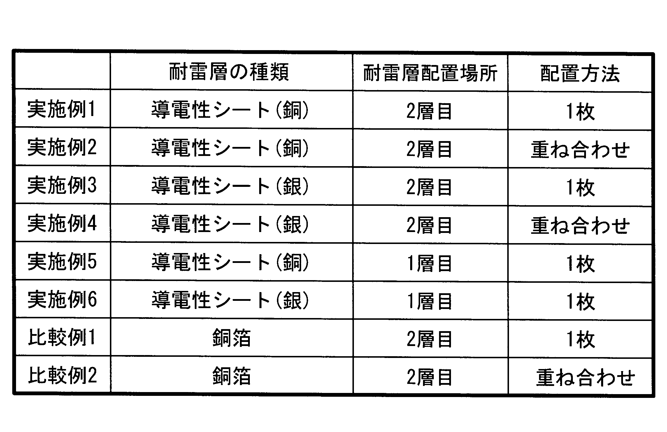
- Table 1 shows the types of lightning-resistant layers, the location of lightning-resistant layers, and the method for arranging lightning-resistant layers.
- a conductive sheet or copper foil produced by the above method as a lightning-resistant layer on a GFRP prepreg (manufactured by Toray, extremely thin).
- CFRP prepreg manufactured by Toray, high-strength elastic unidirectional material in this order to obtain a laminate.
- the side surfaces for molding the two conductive sheets were superposed with a width of 5 mm.
- Example 5 and Example 6 a GFRP prepreg and a CFRP prepreg were arranged in this order on the surface of the conductive sheet opposite to the molding plate side to form a laminate.
- the laminate was placed in a vacuum bag and heated and bonded while evacuating to obtain a resin matrix composite.
- the bonding conditions were as follows: degree of vacuum: 3.4 ⁇ 10 3 Pa, pressure: 5.9 ⁇ 10 5 Pa, heating temperature: 180 ° C., heating time: 2 hours.
- the cross sections of the resin matrix composites of Examples and Comparative Examples were observed with a digital macroscope and a metal microscope.
- the resin matrix composites of Examples 1 and 2 had good adhesion between the conductive sheet and GFRP and good adhesion between the conductive sheet and CFRP.
- the resin matrix composites of Examples 3 and 4 had good adhesion between the conductive sheet and CFRP.
- the resin component of FRP did not enter the overlapping portion of the conductive sheets, and the adhesion between the conductive sheets was good.
- the resin matrix composites of Examples 5 and 6 had good adhesion between the conductive sheet and GFRP.
- the composite materials of Comparative Examples 1 and 2 had good adhesion between the copper foil and GFRP and good adhesion between the copper foil and CFRP. However, it was confirmed that the composite material of Comparative Example 2 had a gap between the copper foils, and the adhesion between the copper foils was poor.
- Example 1 For the resin matrix composites of Example 1, Example 3, and Comparative Example 1, the GFRP around the point where the distance between the terminals was 100 mm was removed to expose the conductive sheet or the copper foil.
- Example 2 Example 4, and Comparative Example 2, for each of the two conductive sheets or copper foils, the GFRP around the point that was 50 mm from the center of the overlapped portion was removed.
- Example 5 and Example 6 the surface of the conductive sheet around the point where the distance between the terminals was 100 mm was polished, and the oxide film was removed.
- the surface resistance of the copper-containing conductive sheet is larger than that of the molding plate side.
- the surface resistance of the copper-containing conductive sheet was larger than the surface resistance of the copper foil, but was a sufficient value as a lightning-resistant layer for aircraft main wing structural materials.
- the silver-containing conductive sheet had substantially the same resistance value on the outer surface side and the molding plate side. In addition, when it heated on 150 degreeC time conditions after silver containing electroconductive sheet preparation, each resistance value became 8 m (ohm).
- the surface resistance of the example was larger than the surface resistance of the example, but it was a sufficient value as a lightning-resistant layer for the aircraft main wing structure material.
Landscapes
- Engineering & Computer Science (AREA)
- Aviation & Aerospace Engineering (AREA)
- Laminated Bodies (AREA)
- Moulding By Coating Moulds (AREA)
Abstract
Description
(第1実施形態)
図1は、第1実施形態の製造方法により製造される樹脂基複合材の断面概略図である。樹脂基複合材10は、第1の樹脂板11、耐雷層として導電層12、第2の樹脂板13が順に積層された構成とされる。このように、導電層を第1及び第2の樹脂板で挟む構成の樹脂基複合材とすることにより、最表面を平滑にすることができる。図1の構成の樹脂基複合材を航空機主翼構造体に適用する場合、主翼構造体最表面に耐雷層を設ける構成と比べて、空力的に有利である。 Hereinafter, embodiments of the present invention will be described.
(First embodiment)
FIG. 1 is a schematic cross-sectional view of a resin matrix composite manufactured by the manufacturing method of the first embodiment. The resin-based
まず、第1の樹脂板11としてのGFRPプリプレグ上に、導電層12としての導電性シートを配置する。複数枚の導電性シートをGFRPプリプレグに配置する際は、隣接する導電性シートの端部を、例えば5mm程度の幅で重ねる。なお、金属粉を含有する樹脂を成形用板上に塗布し乾燥させる上記の方法により作製した導電性シートは、樹脂内の金属粉が成形用板側に沈殿したり、塗布された樹脂の外表面が乾燥時に酸化されたりするため、外表面の抵抗値が成形用板側の抵抗値よりも大きくなる。このように、成形用板側の表面同士が接触するように隣接する導電性シートの端部を重ねて配置すると、接触面での抵抗値の上昇を防止できる。 The
First, a conductive sheet as the
また、本実施形態の樹脂基複合材は、金属粉を含有する樹脂を主成分とする導電性シートを耐雷層とするため、耐雷層と第1及び第2の樹脂板との熱膨張係数の差が小さい。その結果、耐雷層と第1及び第2の樹脂板との密着性が良好である。 As in the present embodiment, by using a conductive sheet (a resin containing metal powder previously formed into a sheet shape), it is possible to prevent erosion of the resin plate by the solvent and generation of water components during heat bonding. A conductive sheet containing a resin as a main component is excellent in handling properties such as superior flexibility and resistance to tearing compared to conventional copper foils. Therefore, the workability at the time of bonding can be greatly improved, and the conductive sheet can be bonded to the resin plate with a large area, which is advantageous.
Moreover, since the resin-based composite material of the present embodiment uses a conductive sheet mainly composed of a resin containing metal powder as a lightning resistant layer, the coefficient of thermal expansion between the lightning resistant layer and the first and second resin plates is The difference is small. As a result, the adhesion between the lightning resistant layer and the first and second resin plates is good.
第2実施形態では、金属粉を含有する樹脂を第1の樹脂板上に塗布することにより、導電層を形成する。なお、樹脂及び金属粉は、第1実施形態と同じ材料とされる。 (Second embodiment)
In the second embodiment, the conductive layer is formed by applying a resin containing metal powder onto the first resin plate. The resin and the metal powder are the same material as in the first embodiment.
第1の樹脂板11としてのGFRPプリプレグ上に、金属粉を含有する樹脂を塗布する。塗布方法は、スプレー塗布でも良いし、コーターを使用して樹脂ペーストを塗布しても良い。塗布後、大気中での加熱乾燥により樹脂中の溶媒を除去するとともに、樹脂を硬化させ、導電層12を形成する。乾燥温度は、使用する樹脂が硬化する温度とされる。 In the second embodiment, the
A resin containing metal powder is applied onto the GFRP prepreg as the
図2は、第3実施形態の製造方法により製造される樹脂基複合材の断面概略図である。樹脂基複合材20は、第1の樹脂板21の一方の表面に耐雷層として導電層22、他方の表面に第2の樹脂板23が形成された構成とされる。 (Third embodiment)
FIG. 2 is a schematic cross-sectional view of a resin matrix composite material manufactured by the manufacturing method of the third embodiment. The
導電層22としての導電性シート上に、第1の樹脂板21としてのGFRPプリプレグを配置する。複数枚の導電性シートを使用する場合は、隣接する導電性シートの端部を、例えば5mm程度の幅で重ねる。次に、GFRPプリプレグ上に、第2の樹脂板23としてのCFRPプリプレグを配置し、積層体とする。なお、積層体は、CFRPプリプレグ上に、GFRPプリプレグ及び導電性シートを順に積層させて形成しても良い。
上記積層体を、真空バッグ中に入れる。真空バッグ内部を排気しながら積層体を175℃から185℃の温度範囲内に加熱して、プリプレグと導電性シートとを接着させ、樹脂基複合材20を作製する。 The
A GFRP prepreg as the
The laminate is placed in a vacuum bag. The laminated body is heated to a temperature range of 175 ° C. to 185 ° C. while evacuating the inside of the vacuum bag, and the prepreg and the conductive sheet are bonded to produce the
第4実施形態では、金属粉を含有する樹脂を第1の樹脂板上に塗布することにより、導電層を形成し、図2に示す構成の樹脂基複合材を製造する。 (Fourth embodiment)
In the fourth embodiment, a conductive layer is formed by applying a resin containing metal powder on the first resin plate, and a resin-based composite material having the configuration shown in FIG. 2 is manufactured.
第1の樹脂板21としてのGFRPプリプレグ上に、スプレーやコーターにより、金属粉を含有する樹脂を塗布する。塗布後、大気中で加熱乾燥させて樹脂中の溶媒を除去するとともに樹脂を硬化させ、導電層22を形成する。
次に、第1の樹脂板21における導電層22が形成された面と反対側の面に、第2の樹脂板23としてのCFRPプリプレグを配置する。導電層、GFRPプリプレグ、及びCFRPプリプレグを積層させた積層体を、真空バッグの中に入れる。真空バッグ内部を排気しながら積層体を175℃から185℃の温度範囲内に加熱して、プリプレグと導電層とを接着させ、樹脂基複合材20を作製する。 In the fourth embodiment, the
A resin containing metal powder is applied onto the GFRP prepreg as the
Next, a CFRP prepreg as the
表面に四フッ化エチレンがコーティングされたアルミ製成形用板上に、銅ペイント(フェノール樹脂)をスプレーして塗布した。銅ペイントが塗布されたアルミ板を、150℃30分の条件で加熱した。放冷後、銅ペイントの膜をアルミ板から剥離し、銅含有導電性シートを得た。銅含有導電性シートの膜厚は、70μmから85μmの範囲内であった。 (Preparation of conductive sheet)
Copper paint (phenolic resin) was sprayed and applied onto an aluminum molding plate whose surface was coated with tetrafluoroethylene. The aluminum plate coated with copper paint was heated at 150 ° C. for 30 minutes. After cooling, the copper paint film was peeled from the aluminum plate to obtain a copper-containing conductive sheet. The film thickness of the copper-containing conductive sheet was in the range of 70 μm to 85 μm.
表1に耐雷層の種類、耐雷層の配置場所、及び耐雷層の配置方法を示す。
実施例1乃至実施例4、及び比較例1及び比較例2では、GFRPプリプレグ(東レ製、極薄型)上に、耐雷層として、上記の方法で作製した導電性シートまたは銅箔(電解銅箔)、CFRPプリプレグ(東レ製、高強度弾力性一方向材)の順で配置し、積層体とした。実施例2及び4、比較例2は、2枚の導電性シートの成型用板側面同士を5mmの幅で重ね合わせた。
実施例5及び実施例6では、導電性シートの成型用板側と反対側の面上に、GFRPプリプレグ、CFRPプリプレグの順で配置し、積層体とした。 (Production of resin matrix composite)
Table 1 shows the types of lightning-resistant layers, the location of lightning-resistant layers, and the method for arranging lightning-resistant layers.
In Examples 1 to 4 and Comparative Examples 1 and 2, a conductive sheet or copper foil (electrolytic copper foil) produced by the above method as a lightning-resistant layer on a GFRP prepreg (manufactured by Toray, extremely thin). ), CFRP prepreg (manufactured by Toray, high-strength elastic unidirectional material) in this order to obtain a laminate. In Examples 2 and 4 and Comparative Example 2, the side surfaces for molding the two conductive sheets were superposed with a width of 5 mm.
In Example 5 and Example 6, a GFRP prepreg and a CFRP prepreg were arranged in this order on the surface of the conductive sheet opposite to the molding plate side to form a laminate.
実施例及び比較例の樹脂基複合材の断面を、デジタル・マクロスコープ及び金属顕微鏡で観察した。実施例1及び2の樹脂基複合材は、導電性シートとGFRPとの密着性、及び、導電性シートとCFRPとの密着性が良好であった。実施例3及び4の樹脂基複合材は、導電性シートとCFRPとの密着性が良好であった。特に実施例4では、導電性シートの重ね合わせ部分にFRPの樹脂成分が進入せず、導電性シート同士の密着性が良好であった。実施例5及び6の樹脂基複合材は、導電性シートとGFRPとの密着性が良好であった。比較例1及び2の複合材は、銅箔とGFRPとの密着性、及び、銅箔とCFRPとの密着性が良好であった。しかし、比較例2の複合材は、銅箔間に隙間があり、銅箔同士の密着性が不良であることが確認された。 (Adhesion evaluation)
The cross sections of the resin matrix composites of Examples and Comparative Examples were observed with a digital macroscope and a metal microscope. The resin matrix composites of Examples 1 and 2 had good adhesion between the conductive sheet and GFRP and good adhesion between the conductive sheet and CFRP. The resin matrix composites of Examples 3 and 4 had good adhesion between the conductive sheet and CFRP. In particular, in Example 4, the resin component of FRP did not enter the overlapping portion of the conductive sheets, and the adhesion between the conductive sheets was good. The resin matrix composites of Examples 5 and 6 had good adhesion between the conductive sheet and GFRP. The composite materials of Comparative Examples 1 and 2 had good adhesion between the copper foil and GFRP and good adhesion between the copper foil and CFRP. However, it was confirmed that the composite material of Comparative Example 2 had a gap between the copper foils, and the adhesion between the copper foils was poor.
実施例及び比較例の樹脂基複合材を、ダイヤモンドカッターを用いて切断し、断面をデジタル・マイクロスコープで観察した。実施例の樹脂基複合材は、いずれもバリは発生しなかった。比較例の樹脂基複合材は、銅箔によるバリが発生しているのが確認された。 (Processability evaluation)
The resin matrix composites of Examples and Comparative Examples were cut using a diamond cutter, and the cross section was observed with a digital microscope. None of the resin matrix composites of the examples produced burrs. In the resin-based composite material of the comparative example, it was confirmed that burrs due to the copper foil were generated.
上記の方法で作製した導電性シートの外表面側及び成型用板側の表面抵抗、及び、上記の銅箔の表面抵抗(表裏2面)を測定した。端子間距離は100mmとした。 (Resistance measurement)
The surface resistance on the outer surface side and the molding plate side of the conductive sheet produced by the above method and the surface resistance (front and back two surfaces) of the copper foil were measured. The distance between terminals was 100 mm.
実施例及び比較例の樹脂基複合材の導電性シートまたは銅箔の表面抵抗(端子間距離:100mm)を測定した。表2に、導電性シート、銅箔、実施例及び比較例の表面抵抗を示す。 For the resin matrix composites of Example 1, Example 3, and Comparative Example 1, the GFRP around the point where the distance between the terminals was 100 mm was removed to expose the conductive sheet or the copper foil. In Example 2, Example 4, and Comparative Example 2, for each of the two conductive sheets or copper foils, the GFRP around the point that was 50 mm from the center of the overlapped portion was removed. In Example 5 and Example 6, the surface of the conductive sheet around the point where the distance between the terminals was 100 mm was polished, and the oxide film was removed.
The surface resistance (distance between terminals: 100 mm) of the conductive sheets or copper foils of the resin matrix composites of Examples and Comparative Examples was measured. Table 2 shows the surface resistance of the conductive sheet, copper foil, examples and comparative examples.
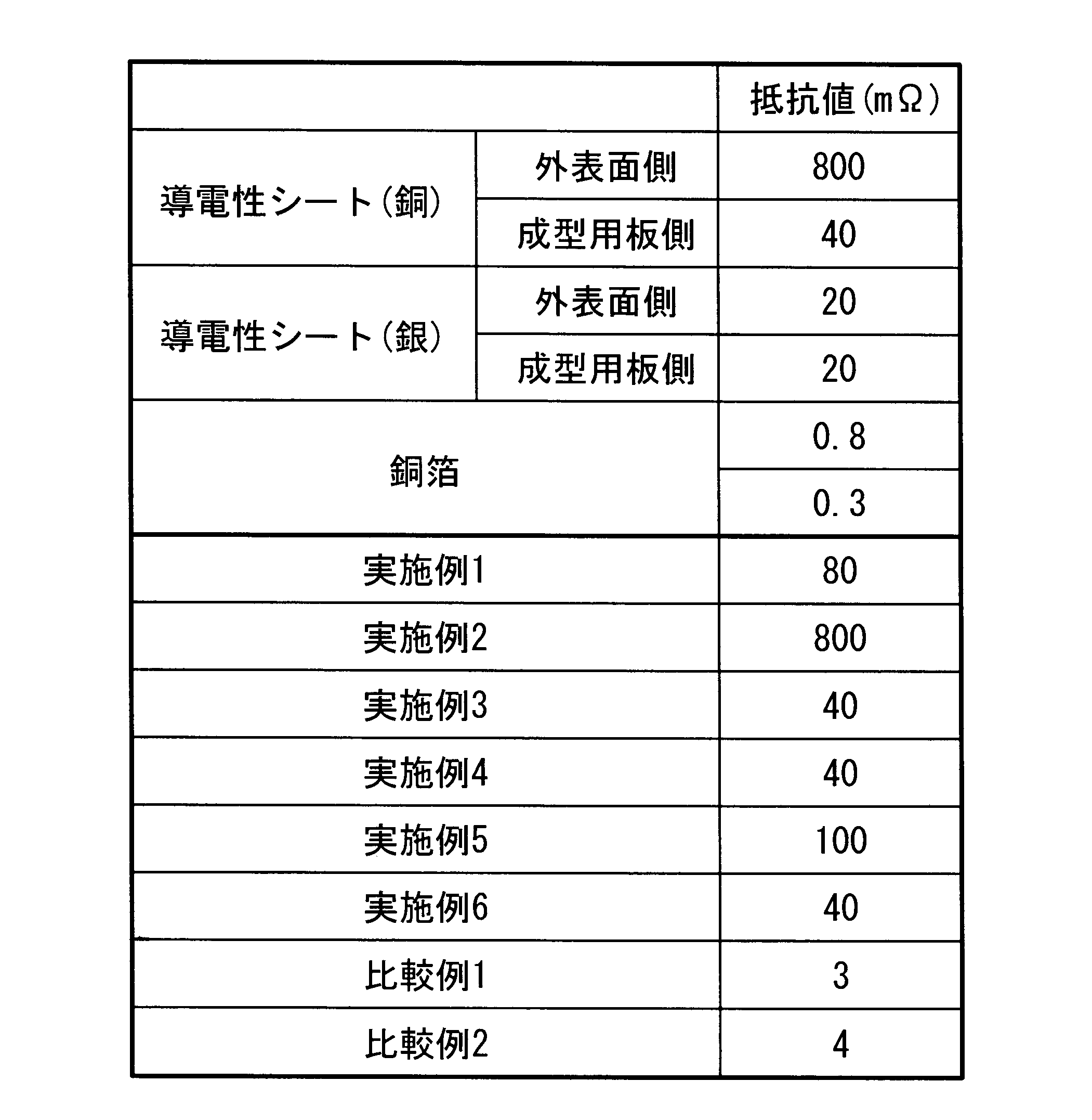
銀含有導電性シートは、外表面側及び成型用板側で抵抗値がほぼ同じであった。なお、銀含有導電性シート作製後に150℃時間の条件で加熱すると、抵抗値がそれぞれ8mΩとなった。 Since the outer surface side of the copper-containing conductive sheet is oxidized during drying, the surface resistance is larger than that of the molding plate side. The surface resistance of the copper-containing conductive sheet was larger than the surface resistance of the copper foil, but was a sufficient value as a lightning-resistant layer for aircraft main wing structural materials.
The silver-containing conductive sheet had substantially the same resistance value on the outer surface side and the molding plate side. In addition, when it heated on 150 degreeC time conditions after silver containing electroconductive sheet preparation, each resistance value became 8 m (ohm).
11,21 第1の樹脂板
12,22 導電層(耐雷層)
13,23 第2の樹脂板 10, 20 Resin-based
13, 23 Second resin plate
Claims (3)
- 繊維で強化された樹脂を主たる要素として構成された第1の樹脂板上に、金属粉を含有する樹脂から構成された導電層と、繊維で強化された樹脂を主たる要素として構成された第2の樹脂板とを順次積層させて積層体を形成する工程と、
該積層体を焼成して、前記第1の樹脂板と前記導電層と前記第2の樹脂板とを接着させて樹脂基複合材を形成する工程とを含む樹脂基複合材の製造方法。 On the first resin plate composed mainly of a resin reinforced with fibers, a conductive layer composed of a resin containing metal powder, and a second composed mainly of a resin reinforced with fibers. Forming a laminate by sequentially laminating the resin plates;
A method for producing a resin-based composite material, comprising: firing the laminate, and bonding the first resin plate, the conductive layer, and the second resin plate to form a resin-based composite material. - 繊維で強化された樹脂を主たる要素として構成された第1の樹脂板の一方の面上に、金属粉を含有する樹脂から構成された導電層を積層し、該導電層が形成された面と反対側の面上に、繊維で強化された樹脂を主たる要素として構成された第2の樹脂板とを順次積層させて積層体を形成する工程と、
該積層体を焼成して、前記第1の樹脂板と前記導電層と前記第2の樹脂板とを接着させて樹脂基複合材を形成する工程とを含む樹脂基複合材の製造方法。 A conductive layer made of a resin containing metal powder is laminated on one surface of the first resin plate that is mainly composed of a resin reinforced with fibers, and the surface on which the conductive layer is formed. A step of sequentially laminating a second resin plate composed mainly of a fiber reinforced resin on the opposite surface to form a laminate;
A method for producing a resin-based composite material, comprising: firing the laminate, and bonding the first resin plate, the conductive layer, and the second resin plate to form a resin-based composite material. - 前記金属粉が、銅粉または銀粉とされる請求項1または請求項2に記載の樹脂基複合材の製造方法。 The method for producing a resin-based composite material according to claim 1 or 2, wherein the metal powder is copper powder or silver powder.
Priority Applications (5)
| Application Number | Priority Date | Filing Date | Title |
|---|---|---|---|
| EP10743663.6A EP2399739A4 (en) | 2009-02-23 | 2010-02-08 | Method for producing resin-based composite |
| CA2752575A CA2752575A1 (en) | 2009-02-23 | 2010-02-08 | Method for producing resin-based composite |
| BRPI1007953A BRPI1007953A2 (en) | 2009-02-23 | 2010-02-08 | method for producing a resin-based compound |
| US13/201,509 US20110297315A1 (en) | 2009-02-23 | 2010-02-08 | Method for producing resin-based composite |
| CN2010800085495A CN102395465A (en) | 2009-02-23 | 2010-02-08 | Method for producing resin-based composite |
Applications Claiming Priority (2)
| Application Number | Priority Date | Filing Date | Title |
|---|---|---|---|
| JP2009039686A JP2010194749A (en) | 2009-02-23 | 2009-02-23 | Method for producing resin-base composite material |
| JP2009-039686 | 2009-02-23 |
Publications (1)
| Publication Number | Publication Date |
|---|---|
| WO2010095536A1 true WO2010095536A1 (en) | 2010-08-26 |
Family
ID=42633819
Family Applications (1)
| Application Number | Title | Priority Date | Filing Date |
|---|---|---|---|
| PCT/JP2010/051830 WO2010095536A1 (en) | 2009-02-23 | 2010-02-08 | Method for producing resin-based composite |
Country Status (7)
| Country | Link |
|---|---|
| US (1) | US20110297315A1 (en) |
| EP (1) | EP2399739A4 (en) |
| JP (1) | JP2010194749A (en) |
| CN (1) | CN102395465A (en) |
| BR (1) | BRPI1007953A2 (en) |
| CA (1) | CA2752575A1 (en) |
| WO (1) | WO2010095536A1 (en) |
Cited By (7)
| Publication number | Priority date | Publication date | Assignee | Title |
|---|---|---|---|---|
| WO2013028830A3 (en) * | 2011-08-25 | 2013-06-27 | Lord Corporation | Lightning strike protection system |
| JP2015507566A (en) * | 2012-01-04 | 2015-03-12 | ザ・ボーイング・カンパニーTheBoeing Company | Aircraft charge dissipation system |
| TWI510367B (en) * | 2013-10-24 | 2015-12-01 | Hon Hai Prec Ind Co Ltd | Composite of metal and resin and method of manufacturing thereof |
| US9302333B2 (en) | 2011-01-05 | 2016-04-05 | Mitsubishi Heavy Industries, Ltd. | End portion processing apparatus |
| US9484123B2 (en) | 2011-09-16 | 2016-11-01 | Prc-Desoto International, Inc. | Conductive sealant compositions |
| US9802714B2 (en) | 2010-12-03 | 2017-10-31 | The Boeing Company | Electric charge dissipation system for aircraft |
| US9840338B2 (en) | 2010-12-03 | 2017-12-12 | The Boeing Company | Electric charge dissipation system for aircraft |
Families Citing this family (9)
| Publication number | Priority date | Publication date | Assignee | Title |
|---|---|---|---|---|
| WO2012091897A1 (en) * | 2010-12-31 | 2012-07-05 | Cytec Technology Corp. | Method of fabricating a composite structure with a conductive surface |
| JP5773679B2 (en) | 2011-02-16 | 2015-09-02 | 三菱重工業株式会社 | Carbon fiber reinforced plastic structure and manufacturing method thereof |
| JP5972967B2 (en) | 2012-03-26 | 2016-08-17 | 三菱重工業株式会社 | Fuel tank, main wing, aircraft fuselage, aircraft and mobile |
| US9776732B2 (en) | 2012-10-09 | 2017-10-03 | Mitsubishi Heavy Industries, Ltd. | Structural material for structure, fuel tank, main wing, and aircraft |
| JP6071686B2 (en) | 2013-03-26 | 2017-02-01 | 三菱重工業株式会社 | Fuel tank, main wing, aircraft fuselage, aircraft and mobile |
| JP6113544B2 (en) * | 2013-03-26 | 2017-04-12 | 三菱重工業株式会社 | Fuel tank, main wing, aircraft fuselage, aircraft and mobile |
| US20160196891A1 (en) * | 2014-09-26 | 2016-07-07 | The Boeing Company | Method for mitigating edge glow |
| JP6580359B2 (en) | 2015-03-31 | 2019-09-25 | 三菱重工業株式会社 | Structure manufacturing method and structure |
| EP3299297B1 (en) | 2016-09-27 | 2018-12-12 | AIRBUS HELICOPTERS DEUTSCHLAND GmbH | A rotary wing aircraft with a structural arrangement that comprises an electrically conductive connection |
Citations (2)
| Publication number | Priority date | Publication date | Assignee | Title |
|---|---|---|---|---|
| JPS6219435A (en) * | 1985-07-18 | 1987-01-28 | Yuka Meramin Kk | Manufacture of electromagnetic wave shielding resin laminated board |
| JPH05147147A (en) * | 1989-12-23 | 1993-06-15 | Bayer Ag | Half-finished product having electrically conductive layer of plastic material |
Family Cites Families (5)
| Publication number | Priority date | Publication date | Assignee | Title |
|---|---|---|---|---|
| US4746389A (en) * | 1987-08-04 | 1988-05-24 | United Technologies Corporation | Method for producing a clean, highly conductive surface for mating composite articles |
| WO2006042251A2 (en) * | 2004-10-08 | 2006-04-20 | Bell Helicopter Textron Inc. | Apparatus and method for ultrasonic processing of laminates |
| CN101466598B (en) * | 2006-03-10 | 2013-02-27 | 豪富公司 | Low density lightning strike protection for use in airplanes |
| GB0622060D0 (en) * | 2006-11-06 | 2006-12-13 | Hexcel Composites Ltd | Improved composite materials |
| JP5770106B2 (en) * | 2009-02-16 | 2015-08-26 | サイテク・テクノロジー・コーポレーシヨン | Co-curing conductive surface film for lightning and electromagnetic interference shielding of thermosetting composites |
-
2009
- 2009-02-23 JP JP2009039686A patent/JP2010194749A/en not_active Withdrawn
-
2010
- 2010-02-08 US US13/201,509 patent/US20110297315A1/en not_active Abandoned
- 2010-02-08 CA CA2752575A patent/CA2752575A1/en not_active Abandoned
- 2010-02-08 WO PCT/JP2010/051830 patent/WO2010095536A1/en active Application Filing
- 2010-02-08 BR BRPI1007953A patent/BRPI1007953A2/en not_active IP Right Cessation
- 2010-02-08 CN CN2010800085495A patent/CN102395465A/en active Pending
- 2010-02-08 EP EP10743663.6A patent/EP2399739A4/en not_active Withdrawn
Patent Citations (2)
| Publication number | Priority date | Publication date | Assignee | Title |
|---|---|---|---|---|
| JPS6219435A (en) * | 1985-07-18 | 1987-01-28 | Yuka Meramin Kk | Manufacture of electromagnetic wave shielding resin laminated board |
| JPH05147147A (en) * | 1989-12-23 | 1993-06-15 | Bayer Ag | Half-finished product having electrically conductive layer of plastic material |
Non-Patent Citations (1)
| Title |
|---|
| See also references of EP2399739A4 * |
Cited By (9)
| Publication number | Priority date | Publication date | Assignee | Title |
|---|---|---|---|---|
| US9802714B2 (en) | 2010-12-03 | 2017-10-31 | The Boeing Company | Electric charge dissipation system for aircraft |
| US9840338B2 (en) | 2010-12-03 | 2017-12-12 | The Boeing Company | Electric charge dissipation system for aircraft |
| US10513347B2 (en) | 2010-12-03 | 2019-12-24 | The Boeing Company | Electric charge dissipation system for aircraft |
| US9302333B2 (en) | 2011-01-05 | 2016-04-05 | Mitsubishi Heavy Industries, Ltd. | End portion processing apparatus |
| WO2013028830A3 (en) * | 2011-08-25 | 2013-06-27 | Lord Corporation | Lightning strike protection system |
| US9007739B2 (en) | 2011-08-25 | 2015-04-14 | Lord Corporation | Lightning strike protection system |
| US9484123B2 (en) | 2011-09-16 | 2016-11-01 | Prc-Desoto International, Inc. | Conductive sealant compositions |
| JP2015507566A (en) * | 2012-01-04 | 2015-03-12 | ザ・ボーイング・カンパニーTheBoeing Company | Aircraft charge dissipation system |
| TWI510367B (en) * | 2013-10-24 | 2015-12-01 | Hon Hai Prec Ind Co Ltd | Composite of metal and resin and method of manufacturing thereof |
Also Published As
| Publication number | Publication date |
|---|---|
| EP2399739A4 (en) | 2013-07-03 |
| EP2399739A1 (en) | 2011-12-28 |
| JP2010194749A (en) | 2010-09-09 |
| CA2752575A1 (en) | 2010-08-26 |
| US20110297315A1 (en) | 2011-12-08 |
| BRPI1007953A2 (en) | 2016-02-23 |
| CN102395465A (en) | 2012-03-28 |
Similar Documents
| Publication | Publication Date | Title |
|---|---|---|
| WO2010095536A1 (en) | Method for producing resin-based composite | |
| JP5788314B2 (en) | Integrated lightning protection material creation system and method | |
| JP5550245B2 (en) | Method for manufacturing metal-ceramic matrix hybrid composite structure, method for manufacturing composite structure, and laminated composite structure | |
| AU2005289392B2 (en) | Thin ply laminates | |
| US20130271891A1 (en) | Metallic Mesh and Lightning Strike Protection System | |
| US11407199B2 (en) | Metal-coated fabrics for fiber-metal laminates | |
| CN108274829A (en) | A kind of light-weighted shielding wallboard of shelter and preparation method thereof with radar invisible function | |
| CN108274830B (en) | Lightweight shelter wallboard with broadband shielding function and preparation method thereof | |
| CN110242358B (en) | Composite blade, method for manufacturing same, and leading edge metal cover forming unit | |
| CN103722808A (en) | Metal foil with carrier | |
| WO2019172020A1 (en) | Leading edge cover member, leading edge cover member unit, composite-material blade, method of manufacturing leading edge cover member, and method of manufacturing composite-material blade | |
| CN101472687B (en) | Corrosion resistant honeycomb | |
| WO2014034112A1 (en) | Exfoliable copper foil attached substrate and circuit board producing method | |
| CN108278928B (en) | Lightweight shielding shelter wallboard with infrared stealth function and preparation method thereof | |
| JP5486020B2 (en) | Circuit board and manufacturing method thereof | |
| JP2020059841A (en) | Integrated surface protection system, composite structure, and method for protecting the same | |
| CN117341288A (en) | Three-dimensional wave-absorbing frequency selecting material and manufacturing method thereof | |
| JP7074266B1 (en) | How to make a sandwich panel | |
| EP3266607B1 (en) | Fiber-reinforced resin structure and method for producing fiber-reinforced resin structure | |
| CN209908843U (en) | Carbon fiber and expansion material combined type fan blade | |
| CN111086224A (en) | Solder for resistance welding of thermoplastic composite material, preparation method and application thereof | |
| TW202208157A (en) | Multi-layer plate having composite material | |
| JP6110406B2 (en) | Manufacturing method of forming jig | |
| CN216017260U (en) | Epoxy-enhanced glass fiber copper-clad plate | |
| JP3299501B2 (en) | Laminate molding plate and laminate |
Legal Events
| Date | Code | Title | Description |
|---|---|---|---|
| WWE | Wipo information: entry into national phase |
Ref document number: 201080008549.5 Country of ref document: CN |
|
| 121 | Ep: the epo has been informed by wipo that ep was designated in this application |
Ref document number: 10743663 Country of ref document: EP Kind code of ref document: A1 |
|
| WWE | Wipo information: entry into national phase |
Ref document number: 2752575 Country of ref document: CA Ref document number: 13201509 Country of ref document: US |
|
| WWE | Wipo information: entry into national phase |
Ref document number: 2010743663 Country of ref document: EP |
|
| NENP | Non-entry into the national phase |
Ref country code: DE |
|
| REG | Reference to national code |
Ref country code: BR Ref legal event code: B01A Ref document number: PI1007953 Country of ref document: BR |
|
| ENP | Entry into the national phase |
Ref document number: PI1007953 Country of ref document: BR Kind code of ref document: A2 Effective date: 20110819 |