JP6113544B2 - Fuel tank, main wing, aircraft fuselage, aircraft and mobile - Google Patents
Fuel tank, main wing, aircraft fuselage, aircraft and mobile Download PDFInfo
- Publication number
- JP6113544B2 JP6113544B2 JP2013064444A JP2013064444A JP6113544B2 JP 6113544 B2 JP6113544 B2 JP 6113544B2 JP 2013064444 A JP2013064444 A JP 2013064444A JP 2013064444 A JP2013064444 A JP 2013064444A JP 6113544 B2 JP6113544 B2 JP 6113544B2
- Authority
- JP
- Japan
- Prior art keywords
- fuel tank
- bolt
- structural member
- aircraft
- main wing
- Prior art date
- Legal status (The legal status is an assumption and is not a legal conclusion. Google has not performed a legal analysis and makes no representation as to the accuracy of the status listed.)
- Active
Links
- 239000002828 fuel tank Substances 0.000 title claims description 41
- 239000004918 carbon fiber reinforced polymer Substances 0.000 claims description 42
- 239000000565 sealant Substances 0.000 claims description 20
- 239000000446 fuel Substances 0.000 claims description 12
- 238000005520 cutting process Methods 0.000 claims description 11
- 239000011159 matrix material Substances 0.000 claims description 9
- 229920000049 Carbon (fiber) Polymers 0.000 claims description 7
- 239000004917 carbon fiber Substances 0.000 claims description 7
- 239000004033 plastic Substances 0.000 claims description 7
- 229920003023 plastic Polymers 0.000 claims description 7
- 239000012779 reinforcing material Substances 0.000 claims description 6
- VNWKTOKETHGBQD-UHFFFAOYSA-N methane Chemical compound C VNWKTOKETHGBQD-UHFFFAOYSA-N 0.000 claims description 5
- 238000010030 laminating Methods 0.000 claims description 3
- 238000000465 moulding Methods 0.000 claims 1
- 238000000034 method Methods 0.000 description 12
- 239000000463 material Substances 0.000 description 9
- 239000007769 metal material Substances 0.000 description 7
- 238000003908 quality control method Methods 0.000 description 6
- 238000004519 manufacturing process Methods 0.000 description 5
- 229910052751 metal Inorganic materials 0.000 description 5
- 239000002184 metal Substances 0.000 description 5
- 239000000835 fiber Substances 0.000 description 4
- 239000002131 composite material Substances 0.000 description 3
- 239000000295 fuel oil Substances 0.000 description 3
- 239000002245 particle Substances 0.000 description 3
- OKTJSMMVPCPJKN-UHFFFAOYSA-N Carbon Chemical compound [C] OKTJSMMVPCPJKN-UHFFFAOYSA-N 0.000 description 2
- PXHVJJICTQNCMI-UHFFFAOYSA-N Nickel Chemical compound [Ni] PXHVJJICTQNCMI-UHFFFAOYSA-N 0.000 description 2
- 239000000805 composite resin Substances 0.000 description 2
- 239000011347 resin Substances 0.000 description 2
- 229920005989 resin Polymers 0.000 description 2
- 229920003002 synthetic resin Polymers 0.000 description 2
- 238000010998 test method Methods 0.000 description 2
- 229920001187 thermosetting polymer Polymers 0.000 description 2
- 229910000838 Al alloy Inorganic materials 0.000 description 1
- RYGMFSIKBFXOCR-UHFFFAOYSA-N Copper Chemical compound [Cu] RYGMFSIKBFXOCR-UHFFFAOYSA-N 0.000 description 1
- RTAQQCXQSZGOHL-UHFFFAOYSA-N Titanium Chemical compound [Ti] RTAQQCXQSZGOHL-UHFFFAOYSA-N 0.000 description 1
- 229910052782 aluminium Inorganic materials 0.000 description 1
- XAGFODPZIPBFFR-UHFFFAOYSA-N aluminium Chemical compound [Al] XAGFODPZIPBFFR-UHFFFAOYSA-N 0.000 description 1
- 229910052799 carbon Inorganic materials 0.000 description 1
- 239000002041 carbon nanotube Substances 0.000 description 1
- 229910021393 carbon nanotube Inorganic materials 0.000 description 1
- 239000011248 coating agent Substances 0.000 description 1
- 238000000576 coating method Methods 0.000 description 1
- 230000006835 compression Effects 0.000 description 1
- 238000007906 compression Methods 0.000 description 1
- 239000004020 conductor Substances 0.000 description 1
- 229910052802 copper Inorganic materials 0.000 description 1
- 239000010949 copper Substances 0.000 description 1
- 239000003822 epoxy resin Substances 0.000 description 1
- 229910052759 nickel Inorganic materials 0.000 description 1
- 229910052755 nonmetal Inorganic materials 0.000 description 1
- 239000004745 nonwoven fabric Substances 0.000 description 1
- 239000003921 oil Substances 0.000 description 1
- -1 plastic Chemical compound 0.000 description 1
- 229920000647 polyepoxide Polymers 0.000 description 1
- 239000002952 polymeric resin Substances 0.000 description 1
- 238000004080 punching Methods 0.000 description 1
- 239000011208 reinforced composite material Substances 0.000 description 1
- 239000000758 substrate Substances 0.000 description 1
- 239000000057 synthetic resin Substances 0.000 description 1
- 239000010936 titanium Substances 0.000 description 1
- 229910052719 titanium Inorganic materials 0.000 description 1
- 229920006305 unsaturated polyester Polymers 0.000 description 1
- 239000013585 weight reducing agent Substances 0.000 description 1
Images


Classifications
-
- B—PERFORMING OPERATIONS; TRANSPORTING
- B64—AIRCRAFT; AVIATION; COSMONAUTICS
- B64D—EQUIPMENT FOR FITTING IN OR TO AIRCRAFT; FLIGHT SUITS; PARACHUTES; ARRANGEMENTS OR MOUNTING OF POWER PLANTS OR PROPULSION TRANSMISSIONS IN AIRCRAFT
- B64D37/00—Arrangements in connection with fuel supply for power plant
- B64D37/32—Safety measures not otherwise provided for, e.g. preventing explosive conditions
-
- B—PERFORMING OPERATIONS; TRANSPORTING
- B32—LAYERED PRODUCTS
- B32B—LAYERED PRODUCTS, i.e. PRODUCTS BUILT-UP OF STRATA OF FLAT OR NON-FLAT, e.g. CELLULAR OR HONEYCOMB, FORM
- B32B7/00—Layered products characterised by the relation between layers; Layered products characterised by the relative orientation of features between layers, or by the relative values of a measurable parameter between layers, i.e. products comprising layers having different physical, chemical or physicochemical properties; Layered products characterised by the interconnection of layers
- B32B7/04—Interconnection of layers
- B32B7/08—Interconnection of layers by mechanical means
-
- B—PERFORMING OPERATIONS; TRANSPORTING
- B32—LAYERED PRODUCTS
- B32B—LAYERED PRODUCTS, i.e. PRODUCTS BUILT-UP OF STRATA OF FLAT OR NON-FLAT, e.g. CELLULAR OR HONEYCOMB, FORM
- B32B1/00—Layered products having a general shape other than plane
-
- B—PERFORMING OPERATIONS; TRANSPORTING
- B32—LAYERED PRODUCTS
- B32B—LAYERED PRODUCTS, i.e. PRODUCTS BUILT-UP OF STRATA OF FLAT OR NON-FLAT, e.g. CELLULAR OR HONEYCOMB, FORM
- B32B15/00—Layered products comprising a layer of metal
- B32B15/04—Layered products comprising a layer of metal comprising metal as the main or only constituent of a layer, which is next to another layer of the same or of a different material
- B32B15/08—Layered products comprising a layer of metal comprising metal as the main or only constituent of a layer, which is next to another layer of the same or of a different material of synthetic resin
-
- B—PERFORMING OPERATIONS; TRANSPORTING
- B32—LAYERED PRODUCTS
- B32B—LAYERED PRODUCTS, i.e. PRODUCTS BUILT-UP OF STRATA OF FLAT OR NON-FLAT, e.g. CELLULAR OR HONEYCOMB, FORM
- B32B27/00—Layered products comprising a layer of synthetic resin
- B32B27/12—Layered products comprising a layer of synthetic resin next to a fibrous or filamentary layer
-
- B—PERFORMING OPERATIONS; TRANSPORTING
- B32—LAYERED PRODUCTS
- B32B—LAYERED PRODUCTS, i.e. PRODUCTS BUILT-UP OF STRATA OF FLAT OR NON-FLAT, e.g. CELLULAR OR HONEYCOMB, FORM
- B32B27/00—Layered products comprising a layer of synthetic resin
- B32B27/18—Layered products comprising a layer of synthetic resin characterised by the use of special additives
- B32B27/20—Layered products comprising a layer of synthetic resin characterised by the use of special additives using fillers, pigments, thixotroping agents
-
- B—PERFORMING OPERATIONS; TRANSPORTING
- B64—AIRCRAFT; AVIATION; COSMONAUTICS
- B64C—AEROPLANES; HELICOPTERS
- B64C3/00—Wings
- B64C3/34—Tanks constructed integrally with wings, e.g. for fuel or water
-
- B—PERFORMING OPERATIONS; TRANSPORTING
- B64—AIRCRAFT; AVIATION; COSMONAUTICS
- B64D—EQUIPMENT FOR FITTING IN OR TO AIRCRAFT; FLIGHT SUITS; PARACHUTES; ARRANGEMENTS OR MOUNTING OF POWER PLANTS OR PROPULSION TRANSMISSIONS IN AIRCRAFT
- B64D37/00—Arrangements in connection with fuel supply for power plant
- B64D37/005—Accessories not provided for in the groups B64D37/02 - B64D37/28
-
- B—PERFORMING OPERATIONS; TRANSPORTING
- B64—AIRCRAFT; AVIATION; COSMONAUTICS
- B64D—EQUIPMENT FOR FITTING IN OR TO AIRCRAFT; FLIGHT SUITS; PARACHUTES; ARRANGEMENTS OR MOUNTING OF POWER PLANTS OR PROPULSION TRANSMISSIONS IN AIRCRAFT
- B64D37/00—Arrangements in connection with fuel supply for power plant
- B64D37/02—Tanks
- B64D37/04—Arrangement thereof in or on aircraft
-
- B—PERFORMING OPERATIONS; TRANSPORTING
- B64—AIRCRAFT; AVIATION; COSMONAUTICS
- B64D—EQUIPMENT FOR FITTING IN OR TO AIRCRAFT; FLIGHT SUITS; PARACHUTES; ARRANGEMENTS OR MOUNTING OF POWER PLANTS OR PROPULSION TRANSMISSIONS IN AIRCRAFT
- B64D37/00—Arrangements in connection with fuel supply for power plant
- B64D37/02—Tanks
- B64D37/06—Constructional adaptations thereof
-
- B—PERFORMING OPERATIONS; TRANSPORTING
- B64—AIRCRAFT; AVIATION; COSMONAUTICS
- B64D—EQUIPMENT FOR FITTING IN OR TO AIRCRAFT; FLIGHT SUITS; PARACHUTES; ARRANGEMENTS OR MOUNTING OF POWER PLANTS OR PROPULSION TRANSMISSIONS IN AIRCRAFT
- B64D45/00—Aircraft indicators or protectors not otherwise provided for
- B64D45/02—Lightning protectors; Static dischargers
-
- B—PERFORMING OPERATIONS; TRANSPORTING
- B32—LAYERED PRODUCTS
- B32B—LAYERED PRODUCTS, i.e. PRODUCTS BUILT-UP OF STRATA OF FLAT OR NON-FLAT, e.g. CELLULAR OR HONEYCOMB, FORM
- B32B2262/00—Composition or structural features of fibres which form a fibrous or filamentary layer or are present as additives
- B32B2262/10—Inorganic fibres
- B32B2262/106—Carbon fibres, e.g. graphite fibres
-
- B—PERFORMING OPERATIONS; TRANSPORTING
- B32—LAYERED PRODUCTS
- B32B—LAYERED PRODUCTS, i.e. PRODUCTS BUILT-UP OF STRATA OF FLAT OR NON-FLAT, e.g. CELLULAR OR HONEYCOMB, FORM
- B32B2307/00—Properties of the layers or laminate
- B32B2307/20—Properties of the layers or laminate having particular electrical or magnetic properties, e.g. piezoelectric
-
- B—PERFORMING OPERATIONS; TRANSPORTING
- B32—LAYERED PRODUCTS
- B32B—LAYERED PRODUCTS, i.e. PRODUCTS BUILT-UP OF STRATA OF FLAT OR NON-FLAT, e.g. CELLULAR OR HONEYCOMB, FORM
- B32B2605/00—Vehicles
-
- B—PERFORMING OPERATIONS; TRANSPORTING
- B32—LAYERED PRODUCTS
- B32B—LAYERED PRODUCTS, i.e. PRODUCTS BUILT-UP OF STRATA OF FLAT OR NON-FLAT, e.g. CELLULAR OR HONEYCOMB, FORM
- B32B2605/00—Vehicles
- B32B2605/18—Aircraft
-
- Y—GENERAL TAGGING OF NEW TECHNOLOGICAL DEVELOPMENTS; GENERAL TAGGING OF CROSS-SECTIONAL TECHNOLOGIES SPANNING OVER SEVERAL SECTIONS OF THE IPC; TECHNICAL SUBJECTS COVERED BY FORMER USPC CROSS-REFERENCE ART COLLECTIONS [XRACs] AND DIGESTS
- Y02—TECHNOLOGIES OR APPLICATIONS FOR MITIGATION OR ADAPTATION AGAINST CLIMATE CHANGE
- Y02T—CLIMATE CHANGE MITIGATION TECHNOLOGIES RELATED TO TRANSPORTATION
- Y02T50/00—Aeronautics or air transport
- Y02T50/40—Weight reduction
Description
本発明は、構造部材として炭素繊維強化プラスチックを用いた燃料タンク、主翼、航空機胴体、航空機及び移動体に関するものである。 The present invention relates to a fuel tank, a main wing, an aircraft fuselage, an aircraft, and a moving body using carbon fiber reinforced plastic as a structural member.
航空機の主翼は、燃料を収容することが可能な燃料タンクとして使用される場合がある。主翼と一体化し、翼構造を油が漏れない液密構造とした燃料タンクは、インテグラルタンクと呼ばれる。インテグラルタンクは、重量軽減を目的として、複合材、例えば炭素繊維強化プラスチック(CFRP)が適用される傾向にある。CFRPは、補強材として炭素繊維が用いられ、マトリックスとして合成樹脂が用いられる。 An aircraft main wing may be used as a fuel tank capable of containing fuel. A fuel tank that is integrated with the main wing and has a liquid-tight structure that prevents oil from leaking is called an integral tank. The integral tank tends to be applied with a composite material such as carbon fiber reinforced plastic (CFRP) for the purpose of weight reduction. CFRP uses carbon fiber as a reinforcing material and synthetic resin as a matrix.
特許文献1では、3次元繊維強化樹脂複合材の発明であって、生産性を損なうことなく、繊維強化樹脂複合材に導電性を付与するため、耳糸が面内方向糸より導電性の高い導電性材料から構成される技術が開示されている。また、特許文献2では、プリプレグ及び炭素繊維強化複合材料の発明であって、優れた耐衝撃性と導電性とを兼ね備えることを目的として、導電性の粒子又は繊維を含ませる技術が開示されている。更に、特許文献3では、改良型複合材料の発明であって、導電性を有し、標準の複合材料と比較してほとんど又は全く重量増加させないことを目的として、高分子樹脂中に分散した導電性粒子を含ませる技術が開示されている。
In patent document 1, it is invention of a three-dimensional fiber reinforced resin composite material, Comprising: In order to provide electroconductivity to a fiber reinforced resin composite material without impairing productivity, an ear thread has higher electroconductivity than an in-plane direction thread | yarn A technique composed of a conductive material is disclosed. Patent Document 2 discloses an invention of a prepreg and a carbon fiber reinforced composite material, and discloses a technique of including conductive particles or fibers for the purpose of combining excellent impact resistance and conductivity. Yes. Further,
ところで、航空機の燃料タンクにおいて、複数の材料同士を締結する場合、ボルトが用いられている。このとき、主翼への着雷時に、雷電流がボルト締結部を流れるとき、ボルトの締結孔と締結孔に挿入されたボルトの間でスパークが発生するおそれがある。従来、スパークの発生を防止するため、締結孔の孔径をボルト径よりも小さくする隙間ばめや、材料に形成した孔にスリーブを設置してボルトを締結するスリーブボルトが用いられている。また、ボルトと締結孔の隙間を埋めるため、ボルトにシーラントを塗布して孔にボルトを挿入する場合もある。 By the way, in the fuel tank of an aircraft, when fastening a plurality of materials, a bolt is used. At this time, when a lightning current flows through the bolt fastening portion during a lightning strike on the main wing, there is a possibility that a spark may occur between the bolt fastening hole and the bolt inserted into the fastening hole. Conventionally, in order to prevent the occurrence of sparks, a clearance fit that makes the hole diameter of the fastening hole smaller than the bolt diameter, or a sleeve bolt that fastens the bolt by installing a sleeve in a hole formed in the material has been used. Further, in order to fill a gap between the bolt and the fastening hole, a sealant may be applied to the bolt and the bolt may be inserted into the hole.
しかし、ボルトと材料との間の抵抗を小さくすることが重要であり、締結孔の孔径の品質がそのまま耐雷性能に直結するため、孔径の品質管理要求が厳しくなる。これにより、品質管理に掛かる時間やコストが増加する。
また、スリーブボルトを使用する場合は、スリーブが挿入される孔の周りの材料を破損させながらスリーブを取り付けることになるため、強度が通常のボルトを使用する場合よりも弱まる。また、スリーブによって重量が増加する。
However, it is important to reduce the resistance between the bolt and the material, and the quality of the hole diameter of the fastening hole is directly linked to the lightning resistance performance, so that the quality control requirement of the hole diameter becomes severe. This increases the time and cost required for quality control.
Also, when using a sleeve bolt, the sleeve is attached while damaging the material around the hole into which the sleeve is inserted, so the strength is weaker than when using a normal bolt. Further, the weight is increased by the sleeve.
なお、上述した課題は、CFRP製の材料同士の締結だけでなく、CFRPと金属材料との締結、金属材料同士の締結でも生じる。また、航空機の主翼と一体化したインテグラルタンクに限られず、燃料が流通する燃料電池の容器にも生じる。以下では、燃料電池の容器も燃料タンクに含めて説明する。また、燃料タンクを有する航空機の胴体、航空機以外の燃料タンクを搭載した自動車等の移動体にも同様の課題が生じる。 The above-described problem occurs not only between the CFRP materials but also between the CFRP and the metal material and between the metal materials. Moreover, it is not limited to an integral tank integrated with the main wing of an aircraft, but also occurs in a fuel cell container through which fuel flows. In the following description, the fuel cell container is also included in the fuel tank. In addition, similar problems occur in a mobile body such as an aircraft fuselage having a fuel tank and an automobile equipped with a fuel tank other than an aircraft.
本発明は、このような事情に鑑みてなされたものであって、品質管理における作業時間やコストを低減し、重量の増加を防止することが可能な燃料タンク、主翼、航空機胴体、航空機及び移動体を提供することを目的とする。 The present invention has been made in view of such circumstances, and is capable of reducing work time and cost in quality control and preventing an increase in weight, a fuel tank, a main wing, an aircraft fuselage, an aircraft, and a movement The purpose is to provide a body.
上記課題を解決するために、本発明の燃料タンク、主翼、航空機胴体、航空機及び移動体は以下の手段を採用する。
すなわち、本発明に係る燃料タンクは、炭素繊維を含む補強材と、プラスチックを含むマトリックスとを有する炭素繊維強化プラスチックを用いた構造部材を備え、前記構造部材は、前記炭素繊維強化プラスチックのプリプレグ間に導電性シートが積層され成形されており、ボルトが締結される締結孔が形成されている。
In order to solve the above problems, the fuel tank, the main wing, the aircraft fuselage, the aircraft, and the moving body of the present invention employ the following means.
That is, the fuel tank according to the present invention includes a structural member using a carbon fiber reinforced plastic having a reinforcing material including carbon fiber and a matrix including plastic, and the structural member is provided between the prepregs of the carbon fiber reinforced plastic. A conductive sheet is laminated and formed on the substrate, and a fastening hole for fastening a bolt is formed.
また、本発明に係る燃料タンクは、ボルトが締結される締結孔が形成された構造部材と、前記ボルトと前記締結孔との間に塗布された導電性が付与されているシーラントと、
を備える。
The fuel tank according to the present invention includes a structural member in which a fastening hole to which a bolt is fastened is formed, and a sealant to which conductivity is applied between the bolt and the fastening hole,
Is provided.
また、本発明に係る主翼は、上記の燃料タンクを構造体とし、本発明に係る航空機胴体は、上記の燃料タンクを備える。本発明に係る航空機は、上記の主翼又は航空機胴体を備える。さらに、本発明に係る移動体は、上記の燃料タンクを備える。 The main wing according to the present invention includes the above fuel tank as a structure, and the aircraft fuselage according to the present invention includes the above fuel tank. An aircraft according to the present invention includes the main wing or the aircraft fuselage. Furthermore, the moving body according to the present invention includes the fuel tank described above.
本発明によれば、ボルトの締結部分において、ボルトと構造部材との間の抵抗が小さくなることから、ボルトの締結孔を形成する際の孔径の管理を簡略化でき、品質管理における作業時間やコストを低減し、重量の増加を防止することができる。 According to the present invention, since the resistance between the bolt and the structural member is reduced in the bolt fastening portion, the management of the hole diameter when forming the bolt fastening hole can be simplified, and the work time in quality control and Cost can be reduced and weight increase can be prevented.
以下に、本発明に係る実施形態について、図面を参照して説明する。
[第1実施形態]
まず、本実施形態に係る航空機の主翼1の構成について説明する。
主翼1は、図1及び図2に示すように、上側スキン3と、下側スキン5と、前側スパー7と、後側スパー9と、複数のリブ11などを備える。
上側スキン3及び下側スキン5は、主翼1の外形を構成し、空力面も兼ねる薄板である。上側スキン3及び下側スキン5は、前側スパー7、後側スパー9及びストリンガ(図示せず。)と共に主翼1に作用する引っ張り荷重や、圧縮荷重の一部を受け持つ。
Embodiments according to the present invention will be described below with reference to the drawings.
[First Embodiment]
First, the structure of the main wing 1 of the aircraft according to the present embodiment will be described.
As shown in FIGS. 1 and 2, the main wing 1 includes an
The
前側スパー7及び後側スパー9は、図1に示すように、主翼1の翼長方向に延設される構造部材であって、上側スキン3及び下側スキン5との間に配置される。複数のストリンガは、上側スキン3又は下側スキン5の内側面に主翼1の翼長方向に延設される補助部材であって、前側スパー7と後側スパー9との間に配置される。
As shown in FIG. 1, the
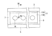
リブ11は、図1に示すように、主翼1の翼幅方向に設けられる構造部材であって、上側スキン3及び下側スキン5の間に配置される。すなわち、リブ11は、前側スパー7及び後側スパー9と略直交する方向に延設される構造部材であって、主翼1の縦断面形状に形成された板状の部材である。リブ11には、図1や図2に示すように、長手方向に複数の開口部14が形成されている。
As shown in FIG. 1, the
主翼1では、前側スパー7、後側スパー9、上側スキン3及び下側スキン5で囲まれた部分が燃料を収容する燃料タンク13として用いられる。燃料タンク13は、機体構造物自体が容器とされており、インテグラルタンク(integral tank)と呼ばれている。そして、前側スパー7、後側スパー9、上側スキン3、下側スキン5及びリブ11は、燃料タンク13の構造部材でもある。燃料タンク13は、燃料が外部に漏れない液密構造を有する。
In the main wing 1, a portion surrounded by the
燃料タンク13の内側には、燃料を燃料タンク13へ供給する燃料配管(図示せず。)、燃料油量を検出する複数の燃料油量計(図示せず。)、及び燃料油量計の配線(図示せず。)などが設置される。
Inside the
次に、燃料タンク13の構造部材について説明する。
燃料タンク13の構造部材、すなわち、前側スパー7、後側スパー9、上側スキン3、下側スキン5及びリブ11は、炭素繊維強化プラスチック(CFRP)が用いられる。そして、燃料タンク13に適用される本実施形態の構造部材は、製造時において、CFRP15のプリプレグ間に導電性シート17が積層されて成形される。したがって、構造部材は、図3に示すように、CFRP15と導電性シート17による積層構造を有する。
Next, the structural member of the
Carbon fiber reinforced plastic (CFRP) is used for the structural members of the
CFRP15は、炭素繊維を含有する補強材と、プラスチックを含有するマトリックスなどからなる。なお、マトリックスは、導電性が付与されなくてもよいし、導電性が付与されてもよい。マトリックスに導電性が付与されている場合、CFRP15自身も、導電性を有する。
The
マトリックスは、例えば、不飽和ポリエステル、エポキシ樹脂などの熱硬化性樹脂等のプラスチックを含む。マトリックスに導電性を付与する方法は、熱硬化性樹脂等のプラスチックに対して導電性を付与する様々な技術を適用することができ、本明細書では詳細な説明を省略する。マトリックスに導電性を付与する方法としては、例えば、プラスチック内に導電性の粒子又は繊維を含ませる方法や、プラスチックそのものに導電性を付与する方法などがある。 The matrix includes, for example, a plastic such as an unsaturated polyester or a thermosetting resin such as an epoxy resin. As a method for imparting conductivity to the matrix, various techniques for imparting conductivity to a plastic such as a thermosetting resin can be applied, and detailed description thereof is omitted in this specification. Examples of a method for imparting conductivity to the matrix include a method of including conductive particles or fibers in the plastic, and a method of imparting conductivity to the plastic itself.
導電性シート17は、シート状であって、電気抵抗の低い部材である。導電性シート17は、金属製でもよいし、非金属製でもよい。金属製の導電性シート17は、例えば、銅又はチタンなどであり、開口を有さない均一なシート状、開口を有するパンチングメタル状、又は、メッシュ状などである。非金属製の導電性シート17は、例えば、炭素繊維などからなり、不織布又はガーゼのような平織りなどに形成されたものを含む。また、炭素繊維は、カーボンナノチューブを用いてもよい。
なお、導電性シート17には、CFRP15の炭素と接触することによって電池を形成する金属、例えば、ニッケルやアルミニウムを用いることは望ましくない。
The
For the
導電性シート17は、構造部材の外部に設けられるスパーク場所、すなわち、雷電流が最終的に流れる場所と接続されている。
The
なお、図3では、リブ11について示しているが、他の部材についても同様である。燃料タンク13において、前側スパー7、後側スパー9、上側スキン3、下側スキン5及びリブ11の全てを、CFRP15を有する構造部材で形成しなくてもよく、部分的にアルミニウム合金等の金属で形成されてもよい。
In FIG. 3, the
燃料タンク13のCFRP15と導電性シート17による構造部材は、燃料が収容される燃料タンク13の内部において、切削加工によって形成された切削面が露出している。例えば、図4に示すように、リブ11がフランジ11Aとウェブ11B等からなる場合、フランジ11Aの端部において、切削面11aが燃料タンク13の内部に露出する。
In the structural member of the
本実施形態では、CFRP15を有する構造部材に、高い導電性を持つ導電性シート17が挿入されていることから、図5に示すように、主翼1のリブ11への着雷時に、着雷地点Pから雷電流Cが構造部材を流れる際、雷電流Cが構造部材のうち導電性シート17にも流れる。その結果、CFRP15に流れ込む雷電流Cが減ることによって、構造部材の切削面11aにおいて、スパークが発生しにくい。
In the present embodiment, since the
本実施形態と異なり、構造部材に導電性シート17が挿入されていない場合、図6に示すように、主翼1のリブ11への着雷時に、着雷地点Pから雷電流CがCFRP部品の表面又は切削面11aを流れる際、補強材の端部において、補強材間でスパークD(図6参照)が発生するおそれがある。従来、このスパーク対策として、図6に示すようにCFRP部品の表面又は切削面11aにシーラント12などを塗布し、発生した電流を内部に閉じ込める方法が採用されている。しかし、シーラント12の塗布作業によって、燃料タンク13の製造工程は、作業時間やコストが増加する。また、塗布されたシーラント12によって、主翼1の重量が増える。
Unlike the present embodiment, when the
これに対して、本実施形態によれば、CFRP15を有する構造部材に、高い導電性を持つ導電性シート17が挿入されているため、切削面11aが燃料タンク13の内部に露出していたとしても、構造部材の切削面11aにおけるスパークの発生を防止できる。その結果、構造部材の表面又は切削面11aに塗布されるシーラントを不要としたり、シーラントの塗布方法を簡便化したりすることができる。したがって、燃料タンクの製造工程やシーラント塗布の品質管理について、作業時間やコストを低減できる。また、シーラント分の重量も削減が可能となる。
On the other hand, according to the present embodiment, since the
次に、図7を参照して、上述したCFRP15を有する構造部材と金属材料30との締結構造について説明する。
CFRP15を有する構造部材は、ボルト20が締結される締結孔22が形成されている。そして、ボルト20には導電性を有する導電性シーラント23が塗布されて、ボルト20が締結孔22に挿入される。その結果、ボルト20と締結孔22との間には導電性シーラント23が設置される。
CFRP15を有する構造部材と金属材料30は、ボルト20とナット21によって締め付けられることによって、互いに強固に固定される。なお、導電性シーラント23を製造する方法は、シーラントに導電性を付与する様々な技術を適用することができ、本明細書では詳細な説明を省略する。
Next, with reference to FIG. 7, the fastening structure of the structural member having the
The structural member having the
The structural member having the
このような締結構造では、ボルト20と上述した導電性シート17とが導電性シーラント23を介して電気的に接触することによって、ボルト20とCFRP15を有する構造部材との間の抵抗を小さくすることができ、着雷時のスパークの発生を低減又は防止できる。特に、締結孔22にボルト20の皿部分に対応した円錐状の開口が形成され、開口部分に導電性シート17が位置するように構造部材が形成されている場合、ボルト20と導電性シート17の距離が互いに短くなる。この場合、確実にボルト20とCFRP15を有する構造部材との間の抵抗を小さくできる。
また、導電性シーラント23がボルト20と締結孔22との間に設置される場合に限定されず、ボルト20と締結孔22との間に導電性シーラント23が設置されない領域が生じる場合もある。この場合、ボルト20と上述した導電性シート17とが物理的に接触することによって、ボルト20とCFRP15を有する構造部材との間の抵抗を小さくすることができ、着雷時のスパークの発生を低減又は防止できる。
したがって、従来のように、隙間ばめのための孔径の形成が不要になり、ボルトの締結孔を形成する際の孔径の管理を簡略化でき、品質管理における作業時間やコストを低減し、重量の増加を防止することができる。また、スリーブボルトの使用もしなくてよいため、強度低下がなく、同じ強度を確保しようとする場合、より軽量化を図ることができる。
In such a fastening structure, the resistance between the
Further, the
Therefore, unlike the conventional case, it is not necessary to form a hole diameter for clearance fitting, management of the hole diameter when forming a bolt fastening hole can be simplified, work time and cost in quality control can be reduced, and weight can be reduced. Can be prevented from increasing. Further, since it is not necessary to use a sleeve bolt, there is no reduction in strength, and when attempting to secure the same strength, the weight can be further reduced.
次に、本発明の第1実施形態と、従来例のそれぞれについて、試験体を作成し、耐雷試験を実施した結果について説明する。
本試験では、導電性を有する導電性シート17が積層されたCFRPを備える構造部材(本実施形態)と、導電性シート17が積層されていないCFRP(従来)とにおいて、試験体に大電流波形を印加してスパークが発生する電流値の違いを比較した。
耐雷試験の試験方法は、SAE internationalのAircraft Lightning Test Methods(ARP5416)のConducted Current Testの記載に従った。試験体に印加した大電流波形は、ARP5412Aに規定される雷模擬電流のコンポーネントA波形である。
Next, a description will be given of the results of creating a specimen and conducting a lightning resistance test for each of the first embodiment of the present invention and the conventional example.
In this test, a large current waveform is applied to a test specimen in a structural member (this embodiment) including CFRP in which a
The test method of the lightning resistance test was in accordance with the description of the Conducted Current Test of SAE international's Aircraft Lightning Test Methods (ARP5416). The large current waveform applied to the specimen is the component A waveform of the simulated lightning current defined in ARP5412A.
図8は、各試験体における相対スパーク発生電流[%]を示している。導電性シート17の種類又は積層枚数の異なる複数の試験体に対して耐雷試験を実施した結果、図7に示す結果が得られた。図8では、導電性シートが積層されていないCFRPのスパーク発生電流値を100%としたときの各試験体のスパーク発生電流値を割合で示している。
FIG. 8 shows the relative spark generation current [%] in each specimen. As a result of conducting a lightning resistance test on a plurality of test specimens having different types of
導電性シート17が積層されたCFRPを備える構造部材の試験体として、非金属製の導電性シート17を1枚積層したもの、及び非金属製の導電性シート17を4枚積層したものを用意した。
試験結果によれば、本実施形態に係る試験体は、相対スパーク発生電流が高くなり、導電性シート17が積層されていないCFRPに比べて、着雷時の雷電流によるスパークの発生を抑制できることが確認された。
また、積層するシートの枚数が1枚、4枚のいずれの場合でも、相対スパーク発生電流がほぼ同値であり、少なくとも1枚の導電性シート17がCFRPに積層されることによって、着雷時の雷電流によるスパークの発生を抑制できることが確認された。
Prepared as a test body of a structural member having a CFRP laminated with a
According to the test results, the test body according to the present embodiment has a higher relative spark generation current, and can suppress the occurrence of a spark due to a lightning current at the time of lightning compared to CFRP in which the
In addition, when the number of sheets to be stacked is one or four, the relative spark generation current is substantially the same, and by laminating at least one
なお、上述した本発明の第1実施形態は、CFRPと金属材料との締結において、CFRPを有する構造部材に導電性シート17を積層する場合について説明したが、本発明はこの例に限定されない。すなわち、導電性シート17が積層されたCFRPを用いずに、ボルト20と締結孔22との間に導電性シーラント23を塗布するだけでもよい。この場合でも、ボルト20と締結孔22が形成された材料との間の抵抗を小さくすることができ、ボルト20と締結孔22との間に発生するスパークを防止できる。
In addition, although 1st Embodiment of this invention mentioned above demonstrated the case where the
また、上述した本発明の第1実施形態は、CFRPと金属材料との締結による場合について説明したが、本発明はこの例に限定されない。すなわち、CFRP製の材料同士の締結にも適用できる。そして、ボルト20と締結孔22との間に導電性シーラント23を塗布するという発明は、金属材料同士の締結の場合にも適用できる。
Moreover, although 1st Embodiment of this invention mentioned above demonstrated the case by the fastening of CFRP and a metal material, this invention is not limited to this example. That is, the present invention can also be applied to fastening between CFRP materials. And the invention of apply | coating the
さらに、上述した実施形態は、航空機の主翼と一体化したインテグラルタンクと呼ばれる燃料タンク13の場合について説明したが、本発明は、この例に限られない。例えば、燃料が流通する燃料電池の容器(燃料タンク)に用いられる構造部材にも適用できる。また、航空機の胴体に設置される燃料タンクの構造部材、航空機以外の自動車等の移動体に搭載される燃料タンクの構造部材にも適用可能である。
Furthermore, although embodiment mentioned above demonstrated the case of the
1 主翼
3 上側スキン
5 下側スキン
7 前側スパー
9 後側スパー
11 リブ
11a 切削面
11A フランジ
11B ウェブ
12 シーラント
13 燃料タンク
15 CFRP
17 導電性シート
1
17 Conductive sheet
Claims (6)
前記構造部材は、前記炭素繊維強化プラスチックのプリプレグ間に導電性シートが積層され成形されており、ボルトが締結される締結孔が設けられ、
燃料が収容される内部に、前記構造部材の切削面が露出している燃料タンク。 A structural member using a carbon fiber reinforced plastic having a reinforcing material containing carbon fiber and a matrix containing plastic,
The structural member is formed by laminating and molding a conductive sheet between the prepregs of the carbon fiber reinforced plastic, and provided with a fastening hole for fastening a bolt,
A fuel tank in which a cutting surface of the structural member is exposed inside the fuel.
Priority Applications (8)
| Application Number | Priority Date | Filing Date | Title |
|---|---|---|---|
| JP2013064444A JP6113544B2 (en) | 2013-03-26 | 2013-03-26 | Fuel tank, main wing, aircraft fuselage, aircraft and mobile |
| CA2907845A CA2907845C (en) | 2013-03-26 | 2014-01-28 | Fuel tank, main wings, aircraft fuselage, aircraft, and moving body |
| CN201480018287.9A CN105102319B (en) | 2013-03-26 | 2014-01-28 | Fuel tank, main wing, aviation machine fuselage, aviation machine and moving body |
| PCT/JP2014/051831 WO2014156274A1 (en) | 2013-03-26 | 2014-01-28 | Fuel tank, main wings, aircraft fuselage, aircraft, and moving body |
| EP14776202.5A EP2979977B1 (en) | 2013-03-26 | 2014-01-28 | Fuel tank, main wings, aircraft fuselage, aircraft, and moving body |
| US14/780,156 US20160052638A1 (en) | 2013-03-26 | 2014-01-28 | Fuel tank, main wings, aircraft fuselage, aircraft, and moving body |
| BR112015024865A BR112015024865A8 (en) | 2013-03-26 | 2014-01-28 | fuel tank, main wings, aircraft fuselage, aircraft and mobile structure |
| RU2015140425A RU2641404C2 (en) | 2013-03-26 | 2014-01-28 | Fuel tank, main wings, aircraft body, flying vehicle and vehicle |
Applications Claiming Priority (1)
| Application Number | Priority Date | Filing Date | Title |
|---|---|---|---|
| JP2013064444A JP6113544B2 (en) | 2013-03-26 | 2013-03-26 | Fuel tank, main wing, aircraft fuselage, aircraft and mobile |
Publications (3)
| Publication Number | Publication Date |
|---|---|
| JP2014189070A JP2014189070A (en) | 2014-10-06 |
| JP2014189070A5 JP2014189070A5 (en) | 2016-03-31 |
| JP6113544B2 true JP6113544B2 (en) | 2017-04-12 |
Family
ID=51623276
Family Applications (1)
| Application Number | Title | Priority Date | Filing Date |
|---|---|---|---|
| JP2013064444A Active JP6113544B2 (en) | 2013-03-26 | 2013-03-26 | Fuel tank, main wing, aircraft fuselage, aircraft and mobile |
Country Status (8)
| Country | Link |
|---|---|
| US (1) | US20160052638A1 (en) |
| EP (1) | EP2979977B1 (en) |
| JP (1) | JP6113544B2 (en) |
| CN (1) | CN105102319B (en) |
| BR (1) | BR112015024865A8 (en) |
| CA (1) | CA2907845C (en) |
| RU (1) | RU2641404C2 (en) |
| WO (1) | WO2014156274A1 (en) |
Cited By (1)
| Publication number | Priority date | Publication date | Assignee | Title |
|---|---|---|---|---|
| JP7114364B2 (en) | 2018-06-22 | 2022-08-08 | キヤノン株式会社 | Power supply and image forming apparatus |
Families Citing this family (16)
| Publication number | Priority date | Publication date | Assignee | Title |
|---|---|---|---|---|
| JP6139582B2 (en) * | 2015-02-23 | 2017-05-31 | 株式会社Subaru | Aircraft structure, aircraft structure manufacturing method, and aircraft structure design information creation method |
| JP2016190627A (en) * | 2015-03-31 | 2016-11-10 | 三菱重工業株式会社 | Structure manufacturing device, structure manufacturing method, and structure |
| CN105501450B (en) * | 2015-11-30 | 2020-09-18 | 中国航空工业集团公司沈阳飞机设计研究所 | Unmanned aerial vehicle composite material integral oil tank sealing method |
| EP3252842A1 (en) * | 2016-06-01 | 2017-12-06 | Airbus Operations GmbH | Structural composite component and method for configuring a structural composite component |
| GB2551560A (en) * | 2016-06-22 | 2017-12-27 | Airbus Operations Ltd | A method of forming a structural portion of a fuel tank for an aircraft |
| US10052847B2 (en) * | 2016-09-16 | 2018-08-21 | The Boeing Company | Method for promoting electrical conduction between metallic components and composite materials |
| CN106585957B (en) * | 2016-12-14 | 2023-03-31 | 中航通飞研究院有限公司 | Composite material wing integral oil tank and manufacturing method thereof |
| CN107140178A (en) * | 2017-06-05 | 2017-09-08 | 芜湖中科飞机制造有限公司 | The wing structure of basic trainer aircraft |
| CN107264817A (en) * | 2017-06-05 | 2017-10-20 | 芜湖中科飞机制造有限公司 | Wing tank |
| JP6778221B2 (en) | 2018-01-15 | 2020-10-28 | 株式会社Subaru | Fastening structure |
| JP6770987B2 (en) | 2018-03-12 | 2020-10-21 | 株式会社Subaru | Composite structure, aircraft and lightning current induction method |
| US11046416B2 (en) * | 2018-08-03 | 2021-06-29 | Aurora Flight Sciences Corporation | Combination flight and ground apparatus for a vehicle |
| US11038334B2 (en) | 2019-01-14 | 2021-06-15 | The Boeing Company | Aircraft wing composite ribs having electrical grounding paths |
| CN111113947A (en) * | 2019-12-18 | 2020-05-08 | 华侨大学 | FASE racing car PMI fin and forming process thereof |
| CN112072335B (en) * | 2020-09-25 | 2022-06-24 | 中国直升机设计研究所 | Conductive structure between composite material structural members and conductive processing method |
| CN113415430A (en) * | 2021-07-30 | 2021-09-21 | 天津爱思达新材料科技有限公司 | Lug beam structure of auxiliary fuel tank of airplane |
Family Cites Families (24)
| Publication number | Priority date | Publication date | Assignee | Title |
|---|---|---|---|---|
| US4556591A (en) * | 1981-09-25 | 1985-12-03 | The Boeing Company | Conductive bonded/bolted joint seals for composite aircraft |
| SU1362681A1 (en) * | 1986-04-10 | 1987-12-30 | Государственный научно-исследовательский институт гражданской авиации | Arrangement for lightning protection of aircraft external fuel tanks |
| US4755904A (en) * | 1986-06-06 | 1988-07-05 | The Boeing Company | Lightning protection system for conductive composite material structure |
| US5866272A (en) * | 1996-01-11 | 1999-02-02 | The Boeing Company | Titanium-polymer hybrid laminates |
| GB9807198D0 (en) * | 1998-04-04 | 1998-06-03 | British Aerospace | Adhesively bonded joints in carbon fibre composite structures |
| US6327132B1 (en) * | 1998-06-10 | 2001-12-04 | Aerospatiale Matra | Spark resistant structure, in particular for aircraft |
| RU2192991C2 (en) * | 2000-12-18 | 2002-11-20 | Открытое Акционерное Общество "Московский Вертолетный Завод Им. М.Л. Миля" | Method of protection of helicopter fuel tanks against thermal effect of lightning current |
| US20050175813A1 (en) * | 2004-02-10 | 2005-08-11 | Wingert A. L. | Aluminum-fiber laminate |
| ES2279664B1 (en) * | 2004-12-30 | 2008-08-01 | Airbus España S.L. | PROTECTION DEVICE AGAINST ELECTRIC SHOCK IN AIRCRAFT. |
| JP4972341B2 (en) | 2006-05-11 | 2012-07-11 | 富士重工業株式会社 | 3D fiber reinforced resin composite |
| JP4969363B2 (en) | 2006-08-07 | 2012-07-04 | 東レ株式会社 | Prepreg and carbon fiber reinforced composites |
| GB0622060D0 (en) | 2006-11-06 | 2006-12-13 | Hexcel Composites Ltd | Improved composite materials |
| JP2010194749A (en) * | 2009-02-23 | 2010-09-09 | Mitsubishi Heavy Ind Ltd | Method for producing resin-base composite material |
| ES2376323B1 (en) * | 2009-02-27 | 2013-01-24 | Airbus Operations, S.L. | IMPROVEMENT OF PROTECTION AGAINST DIRECT IMPACT OF RAYS IN RIVED PANEL AREAS IN CFRP. |
| JP5237170B2 (en) * | 2009-03-30 | 2013-07-17 | 三菱重工業株式会社 | COMPOSITE TANK, WING, AND METHOD FOR PRODUCING COMPOSITE TANK |
| JP5101554B2 (en) * | 2009-03-30 | 2012-12-19 | 三菱重工業株式会社 | Aircraft fuel tank |
| GB0906686D0 (en) * | 2009-04-20 | 2009-06-03 | Airbus Uk Ltd | Edge seal for fibre-reinforced composite structure |
| GB0912016D0 (en) * | 2009-07-10 | 2009-08-19 | Airbus Operations Ltd | Edge glow protection for composite component |
| JP5455541B2 (en) * | 2009-10-14 | 2014-03-26 | 三菱重工業株式会社 | Stringer manufacturing method |
| WO2011050040A1 (en) * | 2009-10-22 | 2011-04-28 | Alcoa Inc. | Enhanced conductivity sleeved fastener and method for making same |
| JP5619446B2 (en) * | 2010-03-23 | 2014-11-05 | 三菱重工業株式会社 | Cap, fastening structure using the cap, and aircraft having the fastening structure |
| US9802714B2 (en) * | 2010-12-03 | 2017-10-31 | The Boeing Company | Electric charge dissipation system for aircraft |
| EP2832645B1 (en) * | 2012-03-26 | 2023-03-08 | Mitsubishi Heavy Industries, Ltd. | Fuel tank, main wing, aircraft fuselage, aircraft, and mobile body |
| JP6071686B2 (en) * | 2013-03-26 | 2017-02-01 | 三菱重工業株式会社 | Fuel tank, main wing, aircraft fuselage, aircraft and mobile |
-
2013
- 2013-03-26 JP JP2013064444A patent/JP6113544B2/en active Active
-
2014
- 2014-01-28 BR BR112015024865A patent/BR112015024865A8/en not_active IP Right Cessation
- 2014-01-28 CN CN201480018287.9A patent/CN105102319B/en not_active Expired - Fee Related
- 2014-01-28 CA CA2907845A patent/CA2907845C/en active Active
- 2014-01-28 US US14/780,156 patent/US20160052638A1/en not_active Abandoned
- 2014-01-28 RU RU2015140425A patent/RU2641404C2/en active
- 2014-01-28 EP EP14776202.5A patent/EP2979977B1/en active Active
- 2014-01-28 WO PCT/JP2014/051831 patent/WO2014156274A1/en active Application Filing
Cited By (1)
| Publication number | Priority date | Publication date | Assignee | Title |
|---|---|---|---|---|
| JP7114364B2 (en) | 2018-06-22 | 2022-08-08 | キヤノン株式会社 | Power supply and image forming apparatus |
Also Published As
| Publication number | Publication date |
|---|---|
| BR112015024865A2 (en) | 2017-07-18 |
| RU2641404C2 (en) | 2018-01-17 |
| BR112015024865A8 (en) | 2019-12-17 |
| CN105102319B (en) | 2018-09-28 |
| WO2014156274A1 (en) | 2014-10-02 |
| JP2014189070A (en) | 2014-10-06 |
| CA2907845C (en) | 2018-02-13 |
| CA2907845A1 (en) | 2014-10-02 |
| EP2979977B1 (en) | 2018-08-15 |
| RU2015140425A (en) | 2017-04-27 |
| EP2979977A4 (en) | 2016-12-14 |
| US20160052638A1 (en) | 2016-02-25 |
| EP2979977A1 (en) | 2016-02-03 |
| CN105102319A (en) | 2015-11-25 |
Similar Documents
| Publication | Publication Date | Title |
|---|---|---|
| JP6113544B2 (en) | Fuel tank, main wing, aircraft fuselage, aircraft and mobile | |
| EP2415693B1 (en) | Composite tank, manufacturing method therefor, and wing | |
| JP6071686B2 (en) | Fuel tank, main wing, aircraft fuselage, aircraft and mobile | |
| JP5972967B2 (en) | Fuel tank, main wing, aircraft fuselage, aircraft and mobile | |
| JP5852255B2 (en) | Structural materials, fuel tanks, main wings and aircraft | |
| US20150044925A1 (en) | Structural material for structure |
Legal Events
| Date | Code | Title | Description |
|---|---|---|---|
| A521 | Request for written amendment filed |
Free format text: JAPANESE INTERMEDIATE CODE: A523 Effective date: 20160215 |
|
| A621 | Written request for application examination |
Free format text: JAPANESE INTERMEDIATE CODE: A621 Effective date: 20160215 |
|
| TRDD | Decision of grant or rejection written | ||
| A01 | Written decision to grant a patent or to grant a registration (utility model) |
Free format text: JAPANESE INTERMEDIATE CODE: A01 Effective date: 20170214 |
|
| A61 | First payment of annual fees (during grant procedure) |
Free format text: JAPANESE INTERMEDIATE CODE: A61 Effective date: 20170315 |
|
| R150 | Certificate of patent or registration of utility model |
Ref document number: 6113544 Country of ref document: JP Free format text: JAPANESE INTERMEDIATE CODE: R150 |