RU2641404C2 - Fuel tank, main wings, aircraft body, flying vehicle and vehicle - Google Patents
Fuel tank, main wings, aircraft body, flying vehicle and vehicle Download PDFInfo
- Publication number
- RU2641404C2 RU2641404C2 RU2015140425A RU2015140425A RU2641404C2 RU 2641404 C2 RU2641404 C2 RU 2641404C2 RU 2015140425 A RU2015140425 A RU 2015140425A RU 2015140425 A RU2015140425 A RU 2015140425A RU 2641404 C2 RU2641404 C2 RU 2641404C2
- Authority
- RU
- Russia
- Prior art keywords
- fuel tank
- cfrp
- bolt
- fuel
- structural element
- Prior art date
Links
- 239000002828 fuel tank Substances 0.000 title claims abstract description 43
- 239000000565 sealant Substances 0.000 claims abstract description 21
- 239000011159 matrix material Substances 0.000 claims abstract description 10
- 239000004033 plastic Substances 0.000 claims abstract description 9
- 229920003023 plastic Polymers 0.000 claims abstract description 9
- 239000012779 reinforcing material Substances 0.000 claims abstract description 7
- 238000005096 rolling process Methods 0.000 claims abstract description 5
- 239000004918 carbon fiber reinforced polymer Substances 0.000 claims description 42
- 239000000446 fuel Substances 0.000 claims description 16
- 229920000049 Carbon (fiber) Polymers 0.000 claims description 8
- 239000004917 carbon fiber Substances 0.000 claims description 8
- VNWKTOKETHGBQD-UHFFFAOYSA-N methane Chemical compound C VNWKTOKETHGBQD-UHFFFAOYSA-N 0.000 claims description 7
- 238000003908 quality control method Methods 0.000 abstract description 7
- 239000000835 fiber Substances 0.000 abstract description 6
- OKTJSMMVPCPJKN-UHFFFAOYSA-N Carbon Chemical compound [C] OKTJSMMVPCPJKN-UHFFFAOYSA-N 0.000 abstract description 5
- 229910052799 carbon Inorganic materials 0.000 abstract description 4
- 230000004584 weight gain Effects 0.000 abstract description 4
- 235000019786 weight gain Nutrition 0.000 abstract description 4
- 230000000694 effects Effects 0.000 abstract description 2
- 229920002430 Fibre-reinforced plastic Polymers 0.000 abstract 2
- 239000011151 fibre-reinforced plastic Substances 0.000 abstract 2
- 230000002265 prevention Effects 0.000 abstract 1
- 239000000126 substance Substances 0.000 abstract 1
- 238000012360 testing method Methods 0.000 description 15
- 238000000034 method Methods 0.000 description 11
- 239000000463 material Substances 0.000 description 10
- 239000007769 metal material Substances 0.000 description 8
- 229910052751 metal Inorganic materials 0.000 description 5
- 239000002184 metal Substances 0.000 description 5
- 239000002131 composite material Substances 0.000 description 4
- 238000004519 manufacturing process Methods 0.000 description 4
- 239000002245 particle Substances 0.000 description 3
- PXHVJJICTQNCMI-UHFFFAOYSA-N Nickel Chemical compound [Ni] PXHVJJICTQNCMI-UHFFFAOYSA-N 0.000 description 2
- 239000000805 composite resin Substances 0.000 description 2
- 239000011347 resin Substances 0.000 description 2
- 229920005989 resin Polymers 0.000 description 2
- 229920003002 synthetic resin Polymers 0.000 description 2
- 238000010998 test method Methods 0.000 description 2
- 229920001187 thermosetting polymer Polymers 0.000 description 2
- 229910000838 Al alloy Inorganic materials 0.000 description 1
- RYGMFSIKBFXOCR-UHFFFAOYSA-N Copper Chemical compound [Cu] RYGMFSIKBFXOCR-UHFFFAOYSA-N 0.000 description 1
- 239000004593 Epoxy Substances 0.000 description 1
- RTAQQCXQSZGOHL-UHFFFAOYSA-N Titanium Chemical compound [Ti] RTAQQCXQSZGOHL-UHFFFAOYSA-N 0.000 description 1
- 229910052782 aluminium Inorganic materials 0.000 description 1
- XAGFODPZIPBFFR-UHFFFAOYSA-N aluminium Chemical compound [Al] XAGFODPZIPBFFR-UHFFFAOYSA-N 0.000 description 1
- 230000015572 biosynthetic process Effects 0.000 description 1
- 239000002041 carbon nanotube Substances 0.000 description 1
- 229910021393 carbon nanotube Inorganic materials 0.000 description 1
- 239000003795 chemical substances by application Substances 0.000 description 1
- 239000004020 conductor Substances 0.000 description 1
- 229910052802 copper Inorganic materials 0.000 description 1
- 239000010949 copper Substances 0.000 description 1
- 238000002474 experimental method Methods 0.000 description 1
- 239000004744 fabric Substances 0.000 description 1
- 230000036039 immunity Effects 0.000 description 1
- 229910052759 nickel Inorganic materials 0.000 description 1
- 239000004745 nonwoven fabric Substances 0.000 description 1
- 239000002952 polymeric resin Substances 0.000 description 1
- 239000011208 reinforced composite material Substances 0.000 description 1
- 238000010008 shearing Methods 0.000 description 1
- 239000000057 synthetic resin Substances 0.000 description 1
- 239000010936 titanium Substances 0.000 description 1
- 229910052719 titanium Inorganic materials 0.000 description 1
- 229920006305 unsaturated polyester Polymers 0.000 description 1
Images
Classifications
-
- B—PERFORMING OPERATIONS; TRANSPORTING
- B64—AIRCRAFT; AVIATION; COSMONAUTICS
- B64D—EQUIPMENT FOR FITTING IN OR TO AIRCRAFT; FLIGHT SUITS; PARACHUTES; ARRANGEMENTS OR MOUNTING OF POWER PLANTS OR PROPULSION TRANSMISSIONS IN AIRCRAFT
- B64D37/00—Arrangements in connection with fuel supply for power plant
- B64D37/32—Safety measures not otherwise provided for, e.g. preventing explosive conditions
-
- B—PERFORMING OPERATIONS; TRANSPORTING
- B32—LAYERED PRODUCTS
- B32B—LAYERED PRODUCTS, i.e. PRODUCTS BUILT-UP OF STRATA OF FLAT OR NON-FLAT, e.g. CELLULAR OR HONEYCOMB, FORM
- B32B7/00—Layered products characterised by the relation between layers; Layered products characterised by the relative orientation of features between layers, or by the relative values of a measurable parameter between layers, i.e. products comprising layers having different physical, chemical or physicochemical properties; Layered products characterised by the interconnection of layers
- B32B7/04—Interconnection of layers
- B32B7/08—Interconnection of layers by mechanical means
-
- B—PERFORMING OPERATIONS; TRANSPORTING
- B32—LAYERED PRODUCTS
- B32B—LAYERED PRODUCTS, i.e. PRODUCTS BUILT-UP OF STRATA OF FLAT OR NON-FLAT, e.g. CELLULAR OR HONEYCOMB, FORM
- B32B1/00—Layered products having a general shape other than plane
-
- B—PERFORMING OPERATIONS; TRANSPORTING
- B32—LAYERED PRODUCTS
- B32B—LAYERED PRODUCTS, i.e. PRODUCTS BUILT-UP OF STRATA OF FLAT OR NON-FLAT, e.g. CELLULAR OR HONEYCOMB, FORM
- B32B15/00—Layered products comprising a layer of metal
- B32B15/04—Layered products comprising a layer of metal comprising metal as the main or only constituent of a layer, which is next to another layer of the same or of a different material
- B32B15/08—Layered products comprising a layer of metal comprising metal as the main or only constituent of a layer, which is next to another layer of the same or of a different material of synthetic resin
-
- B—PERFORMING OPERATIONS; TRANSPORTING
- B32—LAYERED PRODUCTS
- B32B—LAYERED PRODUCTS, i.e. PRODUCTS BUILT-UP OF STRATA OF FLAT OR NON-FLAT, e.g. CELLULAR OR HONEYCOMB, FORM
- B32B27/00—Layered products comprising a layer of synthetic resin
- B32B27/12—Layered products comprising a layer of synthetic resin next to a fibrous or filamentary layer
-
- B—PERFORMING OPERATIONS; TRANSPORTING
- B32—LAYERED PRODUCTS
- B32B—LAYERED PRODUCTS, i.e. PRODUCTS BUILT-UP OF STRATA OF FLAT OR NON-FLAT, e.g. CELLULAR OR HONEYCOMB, FORM
- B32B27/00—Layered products comprising a layer of synthetic resin
- B32B27/18—Layered products comprising a layer of synthetic resin characterised by the use of special additives
- B32B27/20—Layered products comprising a layer of synthetic resin characterised by the use of special additives using fillers, pigments, thixotroping agents
-
- B—PERFORMING OPERATIONS; TRANSPORTING
- B64—AIRCRAFT; AVIATION; COSMONAUTICS
- B64C—AEROPLANES; HELICOPTERS
- B64C3/00—Wings
- B64C3/34—Tanks constructed integrally with wings, e.g. for fuel or water
-
- B—PERFORMING OPERATIONS; TRANSPORTING
- B64—AIRCRAFT; AVIATION; COSMONAUTICS
- B64D—EQUIPMENT FOR FITTING IN OR TO AIRCRAFT; FLIGHT SUITS; PARACHUTES; ARRANGEMENTS OR MOUNTING OF POWER PLANTS OR PROPULSION TRANSMISSIONS IN AIRCRAFT
- B64D37/00—Arrangements in connection with fuel supply for power plant
- B64D37/005—Accessories not provided for in the groups B64D37/02 - B64D37/28
-
- B—PERFORMING OPERATIONS; TRANSPORTING
- B64—AIRCRAFT; AVIATION; COSMONAUTICS
- B64D—EQUIPMENT FOR FITTING IN OR TO AIRCRAFT; FLIGHT SUITS; PARACHUTES; ARRANGEMENTS OR MOUNTING OF POWER PLANTS OR PROPULSION TRANSMISSIONS IN AIRCRAFT
- B64D37/00—Arrangements in connection with fuel supply for power plant
- B64D37/02—Tanks
- B64D37/04—Arrangement thereof in or on aircraft
-
- B—PERFORMING OPERATIONS; TRANSPORTING
- B64—AIRCRAFT; AVIATION; COSMONAUTICS
- B64D—EQUIPMENT FOR FITTING IN OR TO AIRCRAFT; FLIGHT SUITS; PARACHUTES; ARRANGEMENTS OR MOUNTING OF POWER PLANTS OR PROPULSION TRANSMISSIONS IN AIRCRAFT
- B64D37/00—Arrangements in connection with fuel supply for power plant
- B64D37/02—Tanks
- B64D37/06—Constructional adaptations thereof
-
- B—PERFORMING OPERATIONS; TRANSPORTING
- B64—AIRCRAFT; AVIATION; COSMONAUTICS
- B64D—EQUIPMENT FOR FITTING IN OR TO AIRCRAFT; FLIGHT SUITS; PARACHUTES; ARRANGEMENTS OR MOUNTING OF POWER PLANTS OR PROPULSION TRANSMISSIONS IN AIRCRAFT
- B64D45/00—Aircraft indicators or protectors not otherwise provided for
- B64D45/02—Lightning protectors; Static dischargers
-
- B—PERFORMING OPERATIONS; TRANSPORTING
- B32—LAYERED PRODUCTS
- B32B—LAYERED PRODUCTS, i.e. PRODUCTS BUILT-UP OF STRATA OF FLAT OR NON-FLAT, e.g. CELLULAR OR HONEYCOMB, FORM
- B32B2262/00—Composition or structural features of fibres which form a fibrous or filamentary layer or are present as additives
- B32B2262/10—Inorganic fibres
- B32B2262/106—Carbon fibres, e.g. graphite fibres
-
- B—PERFORMING OPERATIONS; TRANSPORTING
- B32—LAYERED PRODUCTS
- B32B—LAYERED PRODUCTS, i.e. PRODUCTS BUILT-UP OF STRATA OF FLAT OR NON-FLAT, e.g. CELLULAR OR HONEYCOMB, FORM
- B32B2307/00—Properties of the layers or laminate
- B32B2307/20—Properties of the layers or laminate having particular electrical or magnetic properties, e.g. piezoelectric
-
- B—PERFORMING OPERATIONS; TRANSPORTING
- B32—LAYERED PRODUCTS
- B32B—LAYERED PRODUCTS, i.e. PRODUCTS BUILT-UP OF STRATA OF FLAT OR NON-FLAT, e.g. CELLULAR OR HONEYCOMB, FORM
- B32B2605/00—Vehicles
-
- B—PERFORMING OPERATIONS; TRANSPORTING
- B32—LAYERED PRODUCTS
- B32B—LAYERED PRODUCTS, i.e. PRODUCTS BUILT-UP OF STRATA OF FLAT OR NON-FLAT, e.g. CELLULAR OR HONEYCOMB, FORM
- B32B2605/00—Vehicles
- B32B2605/18—Aircraft
-
- Y—GENERAL TAGGING OF NEW TECHNOLOGICAL DEVELOPMENTS; GENERAL TAGGING OF CROSS-SECTIONAL TECHNOLOGIES SPANNING OVER SEVERAL SECTIONS OF THE IPC; TECHNICAL SUBJECTS COVERED BY FORMER USPC CROSS-REFERENCE ART COLLECTIONS [XRACs] AND DIGESTS
- Y02—TECHNOLOGIES OR APPLICATIONS FOR MITIGATION OR ADAPTATION AGAINST CLIMATE CHANGE
- Y02T—CLIMATE CHANGE MITIGATION TECHNOLOGIES RELATED TO TRANSPORTATION
- Y02T50/00—Aeronautics or air transport
- Y02T50/40—Weight reduction
Landscapes
- Engineering & Computer Science (AREA)
- Aviation & Aerospace Engineering (AREA)
- Mechanical Engineering (AREA)
- Laminated Bodies (AREA)
- Cooling, Air Intake And Gas Exhaust, And Fuel Tank Arrangements In Propulsion Units (AREA)
- Fuel Cell (AREA)
Abstract
Description
ОБЛАСТЬ ТЕХНИЧЕСКОГО ПРИМЕНЕНИЯFIELD OF TECHNICAL APPLICATION
[0001][0001]
Настоящее изобретение относится к топливным бакам, основным крыльям, корпусам летательных аппаратов, летательному аппарату и транспортным средствам, в конструктивных элементах которых используется армированный углеродным волокном пластик.The present invention relates to fuel tanks, main wings, aircraft bodies, aircraft and vehicles, in the structural elements of which carbon-fiber reinforced plastic is used.
[0002][0002]
Основное крыло летательного аппарата можно использовать в качестве топливного бака с возможностью хранения топлива. Топливный бак, образующий неотъемлемую часть основного крыла, причем конструктивный блок крыла имеет герметичную конструкцию, предотвращающую утечку топлива, называется встроенным баком. Композитные материалы, такие как армированный углеродным волокном пластик (CFRP), обычно используют для встроенных баков с целью снижения их веса. В CFRP углеродные волокна используют в качестве армирующего материала, а синтетическую смолу используют в качестве матрицы.The main wing of the aircraft can be used as a fuel tank with the ability to store fuel. The fuel tank, which forms an integral part of the main wing, and the structural block of the wing has a sealed structure that prevents fuel leakage, is called an integrated tank. Composite materials, such as carbon fiber reinforced plastic (CFRP), are commonly used for embedded tanks to reduce their weight. In CFRP, carbon fibers are used as a reinforcing material, and a synthetic resin is used as a matrix.
[0003][0003]
В патентном документе 1 раскрыто изобретение трехмерного армированного волокнами композитного материала на основе смолы, в котором волокна кромки образованы из проводящего материала, имеющего более высокий уровень проводимости, чем волокна, ориентированные в плоскости, чтобы придать армированному волокнами композитному материалу на основе смолы проводимость, не снижая эффективности. В патентном документе 2 раскрыто изобретение препрега и армированного углеродными волокнами композитного материала, в который включены проводящие частицы или волокна для обеспечения как отличной ударной прочности, так и проводимости. В патентном документе 3 раскрыто изобретение улучшенного композитного материала, содержащего распределенные в полимерной смоле проводящие частицы, чтобы одновременно с приданием материалу проводимости по существу или полностью избежать повышения его веса в сравнении со стандартным композитным материалом.
СПИСОК ЦИТИРОВАННОЙ ЛИТЕРАТУРЫLITERATURE LITERATURE
Патентная литератураPatent Literature
[0004][0004]
Патентный документ 1: нерассмотренная публикация заявки на патентPatent Document 1: Unexamined Publication of Patent Application
Японии №2007-301838АJapan No. 2007-301838A
Патентный документ 2: нерассмотренная публикация заявки на патентPatent Document 2: Unexamined Publication of Patent Application
Японии №2010-280904АJapan No. 2010-280904A
Патентный документ 3: нерассмотренная публикация заявки на патентPatent Document 3: Unexamined Publication of Patent Application
Японии №2011-168792АJapan No. 2011-168792A
КРАТКОЕ ОПИСАНИЕ ИЗОБРЕТЕНИЯSUMMARY OF THE INVENTION
Техническая проблемаTechnical problem
[0005][0005]
В топливных баках летательных аппаратов для прикрепления разных материалов используют болты. В случае удара молнии в основное крыло и протекания тока молнии в области, скрепленной такими болтами, существует опасность искрообразования между крепежным отверстием болта и болтом, вставленным в крепежное отверстие. До настоящего времени для предотвращения искрообразования использовали ходовые посадки, которые задают диаметр крепежного отверстия меньше диаметра болта, болты с втулками, у которых втулку устанавливают в образованное в материале отверстие, а болт за счет резьбы завинчивают во втулку и т.п. Также для заполнения зазоров между болтом и крепежным отверстием иногда на болт распределяют герметик, а затем вставляют болт в отверстие.In the fuel tanks of aircraft, bolts are used to attach different materials. In the event of a lightning strike in the main wing and the flow of lightning in the area fastened by such bolts, there is a risk of sparking between the mounting hole of the bolt and the bolt inserted into the mounting hole. To date, to prevent sparking, running landings have been used that set the diameter of the mounting hole less than the diameter of the bolt, bolts with bushings, in which the sleeve is installed in the hole formed in the material, and the bolt is screwed into the sleeve due to the thread, etc. Also, to fill the gaps between the bolt and the mounting hole, the sealant is sometimes distributed on the bolt, and then the bolt is inserted into the hole.
[0006][0006]
Однако важно уменьшить сопротивление между болтом и материалом, а также поскольку точность диаметра крепежного отверстия непосредственно связана с характеристикой молниестойкости, к диаметрам отверстий предъявляются все более жесткие требования, связанные с контролем качества. Это увеличивает время, необходимое для проведения контроля качества, и приводит к росту затрат.However, it is important to reduce the resistance between the bolt and the material, and also since the accuracy of the diameter of the mounting hole is directly related to the lightning resistance characteristic, increasingly stringent requirements are imposed on hole diameters related to quality control. This increases the time required for quality control and leads to higher costs.
В то же время в случае использования болтов с втулками материал, окружающий отверстие, в которое вставляют втулку, растрескивается, что приводит к снижению прочности в сравнении со случаем, когда используют обычные болты. Кроме того, втулки повышают вес.At the same time, when using bolts with bushings, the material surrounding the hole into which the sleeve is inserted is cracked, which leads to a decrease in strength compared to the case when using conventional bolts. In addition, bushings increase weight.
[0007][0007]
Следует отметить, что вышеупомянутые проблемы возникают не только при прикреплении одного материала CFRP к другому материалу CFRP, но также и при прикреплении CFRP к металлическому материалу или при прикреплении металлического материала к другому металлическому материалу. Более того, проблемы не ограничены лишь встроенными баками, которые образуют неотъемлемые части основного крыла летательного аппарата, но также возникают в емкостях топливного отсека, через которые течет топливо. В представленных ниже описаниях емкость топливного отсека также считается типом топливного бака. Более того, аналогичные проблемы возникают в корпусах летательных аппаратов, имеющих топливные баки, и в транспортных средствах помимо летательных аппаратов, таких как автомобили, в которых установлены топливные баки.It should be noted that the above problems arise not only when attaching one CFRP material to another CFRP material, but also when attaching CFRP to a metal material or when attaching a metal material to another metal material. Moreover, the problems are not limited only to the built-in tanks, which form integral parts of the main wing of the aircraft, but also arise in the capacities of the fuel compartment through which the fuel flows. In the descriptions below, the fuel cell capacity is also considered a type of fuel tank. Moreover, similar problems arise in aircraft bodies having fuel tanks, and in vehicles other than aircraft, such as cars in which fuel tanks are installed.
[0008][0008]
В свете таких проблем целью настоящего изобретения является обеспечение топливного бака, основных крыльев, корпуса летательного аппарата, летательного аппарата и транспортного средства, способных снижать трудоемкость и сокращать затраты, связанные с контролем качества, а также предотвращать повышения веса.In light of such problems, an object of the present invention is to provide a fuel tank, main wings, an aircraft body, an aircraft and a vehicle capable of reducing labor intensity and reducing costs associated with quality control, as well as preventing weight gain.
Решение проблемыSolution
[0009][0009]
Топливный бак в соответствии с первым аспектом настоящего изобретения включает конструктивный элемент, в котором используется армированный углеродным волокном пластик, имеющий армирующий материал, который содержит углеродное волокно, и матрицу, которая содержит пластик, причем конструктивный элемент образован путем прикатывания проводящего листа между листами препрега из армированного углеродным волокном пластика и образован с крепежным отверстием, в котором закреплен болт.A fuel tank in accordance with a first aspect of the present invention includes a structural member that uses carbon fiber reinforced plastic having a reinforcing material that contains carbon fiber and a matrix that contains plastic, the structural member being formed by rolling a conductive sheet between the reinforced prepreg sheets carbon fiber plastic and formed with a mounting hole in which the bolt is fixed.
[0010][0010]
Кроме того, топливный бак в соответствии со вторым аспектом настоящего изобретения включает конструктивный элемент, в котором образовано крепежное отверстие, в котором закреплен болт, и между болтом и крепежным отверстием нанесен придающий проводимость герметик.In addition, the fuel tank in accordance with the second aspect of the present invention includes a structural element in which a mounting hole is formed in which the bolt is fixed, and a conductive imparting sealant is applied between the bolt and the mounting hole.
[0011][0011]
Основное крыло в соответствии с третьим аспектом настоящего изобретения включает топливный бак, описанный в первом или втором аспекте как конструктивный блок, а корпус летательного аппарата в соответствии с четвертым аспектом настоящего изобретения включает топливный бак, описанный в первом или втором аспекте. Летательный аппарат в соответствии с пятым аспектом настоящего изобретения включает основное крыло, описанное в третьем аспекте, или корпус летательного аппарата, описанный в четвертом аспекте. Более того, транспортное средство в соответствии с шестым аспектом настоящего изобретения включает топливный бак, описанный в первом или втором аспекте.The main wing in accordance with the third aspect of the present invention includes a fuel tank described in the first or second aspect as a structural unit, and the aircraft body in accordance with the fourth aspect of the present invention includes a fuel tank described in the first or second aspect. An aircraft in accordance with a fifth aspect of the present invention includes a main wing described in a third aspect, or an aircraft body described in a fourth aspect. Moreover, the vehicle in accordance with the sixth aspect of the present invention includes a fuel tank described in the first or second aspect.
Преимущественные эффекты изобретенияAdvantageous Effects of the Invention
[0012][0012]
В соответствии с настоящим изобретением сопротивление между болтом и конструктивным элементом может быть снижено в области крепления болта, что позволяет упростить контроль диаметра при образовании крепежного отверстия для болта; это, в свою очередь, снижает трудоемкость, затраты и т.п., связанные с контролем качества, а также позволяет предотвратить повышение веса.In accordance with the present invention, the resistance between the bolt and the structural member can be reduced in the area of the bolt fastening, which makes it easier to control the diameter when forming a fixing hole for the bolt; this, in turn, reduces the complexity, costs, etc., associated with quality control, and also helps prevent weight gain.
Краткое описание рисунковBrief Description of Drawings
[0013][0013]
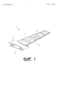
На ФИГ. 1 представлен вид основного крыла в перспективе с частичным разрезом в соответствии с первым вариантом осуществления настоящего изобретения.In FIG. 1 is a partial cross-sectional perspective view of a main wing in accordance with a first embodiment of the present invention.
На ФИГ. 2 представлен продольный вид в поперечном сечении, на котором показано основное крыло в соответствии с первым вариантом осуществления настоящего изобретения.In FIG. 2 is a longitudinal cross-sectional view showing a main wing in accordance with a first embodiment of the present invention.
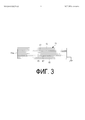
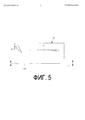
На ФИГ. 3 представлен вид с торца полки нервюры в соответствии с первым вариантом осуществления настоящего изобретения по стрелкам III-III на ФИГ. 5.In FIG. 3 is an end view of a rib shelf in accordance with a first embodiment of the present invention, as shown by arrows III-III in FIG. 5.
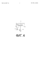
На ФИГ. 4 представлен частичный продольный вид в поперечном сечении верхней обшивки и нервюры в соответствии с первым вариантом осуществления настоящего изобретения, причем сечение выполнено вдоль линии IV-IV на ФИГ. 2.In FIG. 4 is a partial longitudinal cross-sectional view of the upper skin and rib according to the first embodiment of the present invention, the cross section being taken along line IV-IV of FIG. 2.
На ФИГ. 5 представлен вид сверху, на котором показана полка нервюры в соответствии с первым вариантом осуществления настоящего изобретения.In FIG. 5 is a plan view showing a rib of a rib according to a first embodiment of the present invention.
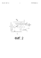
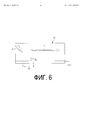
На ФИГ. 6 представлен вид сверху, на котором показана полка стандартной нервюры.In FIG. 6 is a plan view showing a shelf of a standard rib.
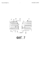
На ФИГ. 7 представлен продольный вид в поперечном сечении, на котором показана прикрепленная область в полке нервюры, в соответствии с первым вариантом осуществления настоящего изобретения.In FIG. 7 is a longitudinal cross-sectional view showing an attached region in a flange of a rib according to a first embodiment of the present invention.
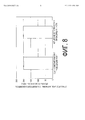
На ФИГ. 8 представлен график, на котором показаны относительные значения тока искрообразования [%] для каждого из испытываемых образцов.In FIG. 8 is a graph showing the relative values of the sparking current [%] for each of the test samples.
Описание вариантов осуществленияDescription of Embodiments
[0014][0014]
Описание варианта осуществления настоящего изобретения будет представлено со ссылкой на чертежи.A description of an embodiment of the present invention will be presented with reference to the drawings.
Первый вариант осуществленияFirst Embodiment
Сначала будет описана конфигурация основного крыла 1 летательного аппарата в соответствии с вариантом осуществления.First, a configuration of a
Как показано на ФИГ. 1 и 2, основное крыло 1 включает верхнюю обшивку 3, нижнюю обшивку 5, передний лонжерон 7, задний лонжерон 9, множество нервюр 11 и т.п.As shown in FIG. 1 and 2, the
Верхняя обшивка 3 и нижняя обшивка 5 составляют внешний контур основного крыла 1 и представляют собой тонкие пластины, которые также действуют как аэродинамические поверхности. Верхняя обшивка 3 и нижняя обшивка 5 вместе с передним лонжероном 7, задним лонжероном 9 и стрингерами (не показаны) несут часть растягивающих нагрузок и сжимающих нагрузок, воздействующих на основное крыло 1.The
[0015][0015]
Как показано на ФИГ. 1, передний лонжерон 7 и задний лонжерон 9 представляют собой конструктивные элементы, проходящие в продольном направлении основного крыла 1 и размещенные между верхней обшивкой 3 и нижней обшивкой 5. Множество стрингеров представляют собой вспомогательные элементы, проходящие в продольном направлении основного крыла 1 на внутренней поверхности верхней обшивки 3 или нижней обшивки 5 и размещенные между передним лонжероном 7 и задним лонжероном 9.As shown in FIG. 1, the
[0016][0016]
Как показано на ФИГ. 1, нервюры 11 представляют собой конструктивные элементы, обеспеченные в поперечном направлении основного крыла 1 и размещенные между верхней обшивкой 3 и нижней обшивкой 5. В частности, нервюры 11 представляют собой конструктивные элементы, проходящие в направлении, приблизительно ортогональном переднему лонжерону 7 и заднему лонжерону 9, и представляют собой пластинчатые элементы, образованные в форме продольного сечения основного крыла 1. Как показано на ФИГ. 1 и 2, в нервюрах 11 в продольном направлении образовано множество отверстий 14.As shown in FIG. 1,
[0017][0017]
В основном крыле 1 секция, окруженная передним лонжероном 7, задним лонжероном 9, верхней обшивкой 3 и нижней обшивкой 5, используется как топливный бак 13, в котором хранится топливо. Топливный бак 13 использует в качестве емкости конструктивные части самого летательного аппарата и называется встроенным баком. Передний лонжерон 7, задний лонжерон 9, верхняя обшивка 3, нижняя обшивка 5 и нервюры 11 также являются конструктивными элементами топливного бака 13. Топливный бак 13 имеет герметичную конструкцию, которая предотвращает утечку топлива во внешний контур.In the main wing, 1 section, surrounded by the
[0018][0018]
Внутри топливного бака 13 размещены топливный трубопровод (не показан) для подачи топлива в топливный бак 13, множество датчиков уровня топлива (не показаны) для детекции уровня топлива, провода для датчиков уровня топлива (не показаны) и т.п.Inside the
[0019][0019]
Ниже будет приведено описание конструктивных элементов топливного бака 13.Below will be a description of the structural elements of the
Армированный углеродным волокном пластик (CFRP) используют для конструктивных элементов топливного бака 13, т.е. переднего лонжерона 7, заднего лонжерона 9, верхней обшивки 3, нижней обшивки 5 и нервюр 11. Конструктивные элементы в соответствии с настоящим вариантом осуществления, которые используются для топливного бака 13, образованы путем прикатывания проводящего листа 17 между листами препрега CFRP 15 во время производства. Соответственно, как показано на ФИГ. 3, конструктивные элементы имеют слоистые структуры, образованные из CFRP 15 и проводящего листа 17.Carbon Fiber Reinforced Plastic (CFRP) is used for structural elements of
[0020][0020]
CFRP 15 состоит из армирующего материала, содержащего углеродное волокно, матрицы, содержащей пластик, и т.п. Следует отметить, что матрице может быть придана или может не быть придана проводимость. В том случае, когда матрице придана проводимость, сам CFRP 15 тоже является проводящим.
[0021][0021]
Матрица включает пластик, такой как термореактивная смола, например ненасыщенный полиэфир или эпоксидная смола. В качестве способа придания матрице проводимости можно применять различные методики придания проводимости пластику, такому как термореактивная смола или т.п. Подробное описание таких методик в настоящем документе представлено не будет. Способы придания проводимости матрице включают, например, включение в пластик проводящих частиц или волокон или придание проводимости самому пластику.The matrix includes plastic, such as a thermosetting resin, for example, an unsaturated polyester or epoxy. As a method for imparting conductivity to a matrix, various techniques for imparting conductivity to plastic, such as a thermosetting resin or the like, can be used. A detailed description of such techniques will not be provided herein. Methods for imparting conductivity to a matrix include, for example, incorporating conductive particles or fibers into the plastic or imparting conductivity to the plastic itself.
[0022][0022]
Проводящий лист 17 представляет собой элемент в форме листа, имеющий низкое электрическое сопротивление. Проводящий лист 17 может быть или может не быть изготовлен из металла. Металлический проводящий лист 17, например, образован из меди, титана или т.п. и имеет форму однородного листа без отверстий, форму штампованного металла с отверстиями, сетчатую форму или т.п. Неметаллический проводящий лист 17, например, образован из углеродного волокна или т.п. и включает элементы, образованные в виде нетканых полотен, тканей гладкого переплетения, аналогичных марле, и т.п. В углеродном волокне можно использовать углеродные нанотрубки.The
Однако следует отметить, что в проводящем листе 17 нежелательно использовать металл, образующий гальванический элемент при вхождении в контакт с углеродом в CFRP 15, такой как никель или алюминий.However, it should be noted that in the
[0023][0023]
Проводящий лист 17 соединен с областью искр, предусмотренной за пределами конструктивных элементов, или, иными словами, с областью, в которой в конечном итоге протекает ток молнии.The
[0024][0024]
Хотя на ФИГ. 3 показаны нервюры 11, аналогичная конструкция используется также для других элементов. В топливном баке 13 весь передний лонжерон 7, задний лонжерон 9, верхняя обшивка 3, нижняя обшивка 5 и нервюры 11 не обязательно должны быть образованы как конструктивные элементы, содержащие CFRP 15, а могут быть частично образованы из металла, такого как алюминиевый сплав.Although in FIG. 3 shows
[0025][0025]
Конструктивные элементы топливного бака 13, образованные из CFRP 15 и проводящего листа 17, имеют поверхности среза, образованные в рамках процесса срезания, которые обращены внутрь топливного бака 13, в котором хранится топливо. Например, как показано на ФИГ. 4, в том случае, когда у каждой нервюры 11 имеется полка 11А, стенка 11В и т.п., поверхность среза 11а в концевой части каждой полки 11А обращена внутрь топливного бака 13.The structural elements of the
[0026][0026]
В настоящем варианте осуществления проводящий лист 17, который имеет высокую проводимость, вставлен в конструктивные элементы, имеющие CFRP 15. Таким образом, как показано на ФИГ. 5, при ударе молнии в нервюру 11 основного крыла 1 и протекании тока молнии С через конструктивный элемент от точки удара Ρ ток молнии С также протекает через проводящий лист 17 внутри конструктивного элемента. В результате этого в CFRP 15 протекает ток молнии С меньшей силы, и, таким образом, искрообразование на поверхностях среза 11а конструктивных элементов затрудняется.In the present embodiment, the
[0027][0027]
В том случае, в котором, в отличие от настоящего варианта осуществления, проводящий лист 17 не вставлен в конструктивный элемент, при ударе молнии в нервюру 11 основного крыла 1 и протекании тока молнии С от точки удара Ρ вдоль поверхности компонента из CFRP или поверхности среза 11а, как показано на ФИГ. 6, существует риск образования искры D между армирующими материалами в концевых частях армирующих материалов (см. ФИГ. 6). Таким образом, до настоящего времени в качестве средства против искр применяли способ, в котором на поверхность компонента из CFRP или на поверхности среза 11а наносили герметик 12 или т.п., как показано на ФИГ. 6, так, чтобы удержать образующийся ток во внутреннем контуре. Однако процесс нанесения герметика 12 приводит к повышению трудоемкости и росту затрат, связанных с производством топливного бака 13. Также из-за нанесения герметика 12 повышается вес основного крыла 1.In the case in which, in contrast to the present embodiment, the
[0028][0028]
В противоположность этому, в соответствии с настоящим вариантом осуществления в конструктивные элементы, имеющие CFRP 15, вставлен проводящий лист 17, имеющий высокую проводимость, и таким образом предотвращается искрообразование на поверхностях среза 11а конструктивных элементов, даже в том случае, когда поверхности среза 11а обращены внутрь топливного бака 13. В результате этого нет необходимости наносить герметик на поверхности или поверхности среза 11а конструктивных элементов, причем способ нанесения герметика можно упростить и т.п. Следовательно, можно снизить трудоемкость и затраты, связанные с производством топливного бака, контролем качества нанесения герметика и т.п. Также можно исключить вес, соответствующий количеству герметика.In contrast, in accordance with the present embodiment, a
[0029][0029]
Далее приведено описание конструкции для прикрепления вышеупомянутого конструктивного элемента, имеющего CFRP 15, к металлическому материалу 30 со ссылкой на ФИГ. 7.The following is a description of the structure for attaching the aforementioned structural
В конструктивном элементе, имеющем CFRP 15, образовано крепежное отверстие 22, в котором закреплен болт 20. На болт 20 наносят проводящий герметик 23, имеющий проводимость, после чего болт 20 вставляют в крепежное отверстие 22. В результате этого проводящий герметик 23 размещен между болтом 20 и крепежным отверстием 22.In the structural
Конструктивный элемент, имеющий CFRP 15, и металлический материал 30 надежно прикреплены друг к другу путем затягивания гайки 21 на болте 20. Следует отметить, что для производства проводящего герметика 23 можно использовать различные методики придания проводимости герметику, подробные описания которых в данной спецификации приведены не будут.A structural
[0030][0030]
При такой конструкции крепления болт 20 и вышеупомянутый проводящий лист 17 электрически связаны посредством проводящего герметика 23. Это позволяет уменьшить сопротивление между болтом 20 и конструктивным элементом, имеющим CFRP 15, что, в свою очередь, позволяет уменьшить или предотвратить искрообразование при ударах молнии. В частности, в том случае, когда в крепежном отверстии 22 образована полость круговой конической формы, соответствующая головной секции болта 20, а конструктивный элемент образован так, что проводящий лист 17 размещен в секции полости, расстояние между болтом 20 и проводящим листом 17 сокращается. В этом случае сопротивление между болтом 20 и конструктивным элементом, имеющим CFRP 15, можно определенно уменьшить.With this attachment structure, the
Однако конструкция не ограничена размещением проводящего герметика 23 между болтом 20 и крепежным отверстием 22, и в ней могут быть области, в которых между болтом 20 и крепежным отверстием 22 проводящий герметик 23 не размещен. В таком случае создание физического контакта между болтом 20 и вышеупомянутым проводящим листом 17 позволяет уменьшить сопротивление между болтом 20 и конструктивным элементом, имеющим CFRP 15, что, в свою очередь, позволяет сократить или предотвратить искрообразование при ударах молнии.However, the design is not limited to the placement of the
Соответственно, отсутствует необходимость в использовании ходовых посадок, как при формировании диаметра традиционными методиками, что позволяет упростить контроль диаметра в процессе образования крепежного отверстия для болта; это, в свою очередь, снижает трудоемкость, затраты и т.п., связанные с контролем качества, а также позволяет предотвратить повышение веса. Более того, отсутствует необходимость в использовании болтов с втулками, что гарантирует отсутствие резкого снижения прочности; таким образом, такая же прочность может быть обеспечена при меньшем весе.Accordingly, there is no need to use landing landings, as in the formation of the diameter by traditional methods, which makes it easier to control the diameter in the process of forming the mounting hole for the bolt; this, in turn, reduces the complexity, costs, etc., associated with quality control, and also helps prevent weight gain. Moreover, there is no need to use bolts with bushings, which guarantees the absence of a sharp decrease in strength; thus, the same strength can be achieved with less weight.
[0031][0031]
Далее будут описаны результаты проведения испытания на молниестойкость испытываемых образцов, созданных в соответствии с первым вариантом осуществления настоящего изобретения, и стандартного примера.Next will be described the results of a lightning test of test samples created in accordance with the first embodiment of the present invention, and a standard example.
В этих экспериментах сильноточный импульс прикладывали к испытываемым образцам конструктивного элемента, имеющего CFRP, в котором прикатывали проводящий лист 17, имеющий проводимость (настоящий вариант осуществления), и CFRP, в котором проводящий лист 17 не прикатан (стандартная структура), и сравнивали различия в значениях тока начала искрообразования.In these experiments, a high current pulse was applied to test samples of a structural member having CFRP in which a
Способ испытания на молниестойкость соответствует «Испытанию на проводимый ток», приведенному в международном стандарте SAE Aircraft Lightning Test Methods («Испытания летательных аппаратов на молниестойкость», ARP5416). Прикладываемый к испытываемым образцам сильноточный импульс представлял собой моделированный импульс компоненты А тока молнии, как определено в ARP5412A.The lightning resistance test method conforms to the “Conducted Current Test” given in the SAE Aircraft Lightning Test Methods international standard (“Lightning Immunity Testing Aircraft”, ARP5416). The high current pulse applied to the test samples was a simulated pulse of lightning current component A, as defined in ARP5412A.
[0032][0032]
На ФИГ. 8 представлен график, на котором показаны относительные значения тока искрообразования [%] для каждого из испытываемых образцов. Результаты, указанные на ФИГ. 7, были получены при проведении испытания на молниестойкость множества испытываемых образцов, имеющих разные типы проводящих листов 17 или разные количества прикатанных в них проводящих листов 17. На ФИГ. 8 показано значение тока искрообразования для каждого испытываемого образца в виде процентного значения, причем за 100% взято значение тока искрообразования для CFRP, в котором прикатанный проводящий лист отсутствует.In FIG. 8 is a graph showing the relative values of the sparking current [%] for each of the test samples. The results indicated in FIG. 7 were obtained when conducting lightning tests on a plurality of test samples having different types of
[0033][0033]
Для конструктивного элемента, имеющего CFRP, в котором прикатан проводящий лист 17, были получены испытываемый образец, в котором прикатан один неметаллический проводящий лист 17, и испытываемый образец, в котором прикатаны четыре неметаллических проводящих листа 17.For a structural member having CFRP in which a
Результаты испытаний подтвердили, что испытываемый образец в соответствии с настоящим вариантом осуществления обеспечивает повышенное относительное значение тока искрообразования и может лучше подавлять искрообразование, связанное с током молнии, чем CFRP, в котором проводящий лист 17 не прикатан.The test results confirmed that the test sample in accordance with this embodiment provides an increased relative value of the sparking current and can better suppress the sparking associated with the lightning current than CFRP, in which the
Более того, относительный ток искрообразования по существу имел такое же значение независимо от того, один или четыре листа были включены в слоистую структуру, и, следовательно, было подтверждено, что прикатывание по меньшей мере одного проводящего листа 17 в CFRP позволяет подавлять искрообразование, вызванное током при ударах молнии.Moreover, the relative sparking current essentially had the same value regardless of whether one or four sheets were included in the layered structure, and therefore it was confirmed that rolling at least one
[0034][0034]
Хотя в вышеупомянутом первом варианте осуществления настоящего изобретения описан случай, в котором проводящий лист 17 прикатан в конструктивных элементах, имеющих CFRP, для ситуаций, в которых CFRP и металлические материалы прикреплены друг к другу, настоящее изобретение не ограничено этим примером. То есть вместо использования CFRP, в котором предусмотрен проводящий лист 17, между болтом 20 и крепежным отверстием 22 можно просто нанести проводящий герметик 23. Даже в таком случае можно уменьшить сопротивление между болтом 20 и материалом, из которого образовано крепежное отверстие 22, и предотвратить искрообразование между болтом 20 и крепежным отверстием 22.Although the above-described first embodiment of the present invention describes a case in which the
[0035][0035]
Кроме того, хотя в вышеупомянутом первом варианте осуществления настоящего изобретения описан случай, в котором CFRP и металлические материалы прикреплены друг к другу, настоящее изобретение не ограничено этим примером. То есть настоящее изобретение может также применяться в случаях, в которых друг к другу прикреплены материалы CFRP. Аналогичным образом, изобретение нанесения проводящего герметика 23 между болтом 20 и крепежным отверстием 22 может также применяться в случаях, в которых друг к другу прикреплены металлические материалы.Furthermore, although a case in which CFRP and metallic materials are attached to each other is described in the above-mentioned first embodiment of the present invention, the present invention is not limited to this example. That is, the present invention can also be applied in cases in which CFRP materials are attached to each other. Similarly, the invention of applying a
[0036][0036]
Более того, хотя в вышеупомянутом варианте осуществления описан топливный бак 13, который называется встроенным баком, образованным зацело с основным крылом 1 летательного аппарата, настоящее изобретение не ограничено этим примером. Настоящее изобретение также может применяться, например, в конструктивных элементах, используемых в емкостях топливного отсека, через которые течет топливо (топливные баки). Настоящее изобретение также можно применять в конструктивных элементах топливных баков, размещенных в корпусе летательного аппарата, и конструктивных элементах топливных баков, установленных в транспортных средствах помимо летательных аппаратов, таких как автомобили.Moreover, although the
Перечень ссылочных обозначенийReference List
[0037][0037]
1 Основное крыло1 Main wing
3 Верхняя обшивка3 Upper trim
5 Нижняя обшивка5 Bottom trim
7 Передний лонжерон7 Front spar
9 Задний лонжерон9 Rear spar
11 Нервюра (-ы)11 Rib (s)
11а Поверхность среза11a cut surface
11А Полка11A Shelf
11В Стенка11V Wall
12 Герметик12 Sealant
13 Топливный бак13 fuel tank
15 CFRP15 CFRP
17 Проводящий лист17 conductive sheet
Claims (8)
Applications Claiming Priority (3)
| Application Number | Priority Date | Filing Date | Title |
|---|---|---|---|
| JP2013-064444 | 2013-03-26 | ||
| JP2013064444A JP6113544B2 (en) | 2013-03-26 | 2013-03-26 | Fuel tank, main wing, aircraft fuselage, aircraft and mobile |
| PCT/JP2014/051831 WO2014156274A1 (en) | 2013-03-26 | 2014-01-28 | Fuel tank, main wings, aircraft fuselage, aircraft, and moving body |
Publications (2)
| Publication Number | Publication Date |
|---|---|
| RU2015140425A RU2015140425A (en) | 2017-04-27 |
| RU2641404C2 true RU2641404C2 (en) | 2018-01-17 |
Family
ID=51623276
Family Applications (1)
| Application Number | Title | Priority Date | Filing Date |
|---|---|---|---|
| RU2015140425A RU2641404C2 (en) | 2013-03-26 | 2014-01-28 | Fuel tank, main wings, aircraft body, flying vehicle and vehicle |
Country Status (8)
| Country | Link |
|---|---|
| US (1) | US20160052638A1 (en) |
| EP (1) | EP2979977B1 (en) |
| JP (1) | JP6113544B2 (en) |
| CN (1) | CN105102319B (en) |
| BR (1) | BR112015024865A8 (en) |
| CA (1) | CA2907845C (en) |
| RU (1) | RU2641404C2 (en) |
| WO (1) | WO2014156274A1 (en) |
Families Citing this family (17)
| Publication number | Priority date | Publication date | Assignee | Title |
|---|---|---|---|---|
| JP6139582B2 (en) * | 2015-02-23 | 2017-05-31 | 株式会社Subaru | Aircraft structure, aircraft structure manufacturing method, and aircraft structure design information creation method |
| JP2016190627A (en) * | 2015-03-31 | 2016-11-10 | 三菱重工業株式会社 | Structure manufacturing device, structure manufacturing method, and structure |
| CN105501450B (en) * | 2015-11-30 | 2020-09-18 | 中国航空工业集团公司沈阳飞机设计研究所 | Unmanned aerial vehicle composite material integral oil tank sealing method |
| EP3252842A1 (en) * | 2016-06-01 | 2017-12-06 | Airbus Operations GmbH | Structural composite component and method for configuring a structural composite component |
| GB2551560A (en) * | 2016-06-22 | 2017-12-27 | Airbus Operations Ltd | A method of forming a structural portion of a fuel tank for an aircraft |
| US10052847B2 (en) * | 2016-09-16 | 2018-08-21 | The Boeing Company | Method for promoting electrical conduction between metallic components and composite materials |
| CN106585957B (en) * | 2016-12-14 | 2023-03-31 | 中航通飞研究院有限公司 | Composite material wing integral oil tank and manufacturing method thereof |
| CN107140178A (en) * | 2017-06-05 | 2017-09-08 | 芜湖中科飞机制造有限公司 | The wing structure of basic trainer aircraft |
| CN107264817A (en) * | 2017-06-05 | 2017-10-20 | 芜湖中科飞机制造有限公司 | Wing tank |
| JP6778221B2 (en) | 2018-01-15 | 2020-10-28 | 株式会社Subaru | Fastening structure |
| JP6770987B2 (en) | 2018-03-12 | 2020-10-21 | 株式会社Subaru | Composite structure, aircraft and lightning current induction method |
| JP7114364B2 (en) | 2018-06-22 | 2022-08-08 | キヤノン株式会社 | Power supply and image forming apparatus |
| US11046416B2 (en) * | 2018-08-03 | 2021-06-29 | Aurora Flight Sciences Corporation | Combination flight and ground apparatus for a vehicle |
| US11038334B2 (en) | 2019-01-14 | 2021-06-15 | The Boeing Company | Aircraft wing composite ribs having electrical grounding paths |
| CN111113947A (en) * | 2019-12-18 | 2020-05-08 | 华侨大学 | FASE racing car PMI fin and forming process thereof |
| CN112072335B (en) * | 2020-09-25 | 2022-06-24 | 中国直升机设计研究所 | Conductive structure between composite material structural members and conductive processing method |
| CN113415430A (en) * | 2021-07-30 | 2021-09-21 | 天津爱思达新材料科技有限公司 | Lug beam structure of auxiliary fuel tank of airplane |
Citations (6)
| Publication number | Priority date | Publication date | Assignee | Title |
|---|---|---|---|---|
| SU1362681A1 (en) * | 1986-04-10 | 1987-12-30 | Государственный научно-исследовательский институт гражданской авиации | Arrangement for lightning protection of aircraft external fuel tanks |
| US6114050A (en) * | 1996-01-11 | 2000-09-05 | The Boeing Company | Titanium-polymer hybrid laminates |
| US6327132B1 (en) * | 1998-06-10 | 2001-12-04 | Aerospatiale Matra | Spark resistant structure, in particular for aircraft |
| RU2192991C2 (en) * | 2000-12-18 | 2002-11-20 | Открытое Акционерное Общество "Московский Вертолетный Завод Им. М.Л. Миля" | Method of protection of helicopter fuel tanks against thermal effect of lightning current |
| US20100264274A1 (en) * | 2009-04-20 | 2010-10-21 | Airbus Operations Limited | Edge seal for fibre-reinforced composite structure |
| WO2012074639A1 (en) * | 2010-12-03 | 2012-06-07 | The Boeing Company | Electric charge dissipation system for aircraft |
Family Cites Families (18)
| Publication number | Priority date | Publication date | Assignee | Title |
|---|---|---|---|---|
| US4556591A (en) * | 1981-09-25 | 1985-12-03 | The Boeing Company | Conductive bonded/bolted joint seals for composite aircraft |
| US4755904A (en) * | 1986-06-06 | 1988-07-05 | The Boeing Company | Lightning protection system for conductive composite material structure |
| GB9807198D0 (en) * | 1998-04-04 | 1998-06-03 | British Aerospace | Adhesively bonded joints in carbon fibre composite structures |
| US20050175813A1 (en) * | 2004-02-10 | 2005-08-11 | Wingert A. L. | Aluminum-fiber laminate |
| ES2279664B1 (en) * | 2004-12-30 | 2008-08-01 | Airbus España S.L. | PROTECTION DEVICE AGAINST ELECTRIC SHOCK IN AIRCRAFT. |
| JP4972341B2 (en) | 2006-05-11 | 2012-07-11 | 富士重工業株式会社 | 3D fiber reinforced resin composite |
| JP4969363B2 (en) | 2006-08-07 | 2012-07-04 | 東レ株式会社 | Prepreg and carbon fiber reinforced composites |
| GB0622060D0 (en) | 2006-11-06 | 2006-12-13 | Hexcel Composites Ltd | Improved composite materials |
| JP2010194749A (en) * | 2009-02-23 | 2010-09-09 | Mitsubishi Heavy Ind Ltd | Method for producing resin-base composite material |
| ES2376323B1 (en) * | 2009-02-27 | 2013-01-24 | Airbus Operations, S.L. | IMPROVEMENT OF PROTECTION AGAINST DIRECT IMPACT OF RAYS IN RIVED PANEL AREAS IN CFRP. |
| JP5237170B2 (en) * | 2009-03-30 | 2013-07-17 | 三菱重工業株式会社 | COMPOSITE TANK, WING, AND METHOD FOR PRODUCING COMPOSITE TANK |
| JP5101554B2 (en) * | 2009-03-30 | 2012-12-19 | 三菱重工業株式会社 | Aircraft fuel tank |
| GB0912016D0 (en) * | 2009-07-10 | 2009-08-19 | Airbus Operations Ltd | Edge glow protection for composite component |
| JP5455541B2 (en) * | 2009-10-14 | 2014-03-26 | 三菱重工業株式会社 | Stringer manufacturing method |
| WO2011050040A1 (en) * | 2009-10-22 | 2011-04-28 | Alcoa Inc. | Enhanced conductivity sleeved fastener and method for making same |
| JP5619446B2 (en) * | 2010-03-23 | 2014-11-05 | 三菱重工業株式会社 | Cap, fastening structure using the cap, and aircraft having the fastening structure |
| EP2832645B1 (en) * | 2012-03-26 | 2023-03-08 | Mitsubishi Heavy Industries, Ltd. | Fuel tank, main wing, aircraft fuselage, aircraft, and mobile body |
| JP6071686B2 (en) * | 2013-03-26 | 2017-02-01 | 三菱重工業株式会社 | Fuel tank, main wing, aircraft fuselage, aircraft and mobile |
-
2013
- 2013-03-26 JP JP2013064444A patent/JP6113544B2/en active Active
-
2014
- 2014-01-28 BR BR112015024865A patent/BR112015024865A8/en not_active IP Right Cessation
- 2014-01-28 CN CN201480018287.9A patent/CN105102319B/en not_active Expired - Fee Related
- 2014-01-28 CA CA2907845A patent/CA2907845C/en active Active
- 2014-01-28 US US14/780,156 patent/US20160052638A1/en not_active Abandoned
- 2014-01-28 RU RU2015140425A patent/RU2641404C2/en active
- 2014-01-28 EP EP14776202.5A patent/EP2979977B1/en active Active
- 2014-01-28 WO PCT/JP2014/051831 patent/WO2014156274A1/en active Application Filing
Patent Citations (6)
| Publication number | Priority date | Publication date | Assignee | Title |
|---|---|---|---|---|
| SU1362681A1 (en) * | 1986-04-10 | 1987-12-30 | Государственный научно-исследовательский институт гражданской авиации | Arrangement for lightning protection of aircraft external fuel tanks |
| US6114050A (en) * | 1996-01-11 | 2000-09-05 | The Boeing Company | Titanium-polymer hybrid laminates |
| US6327132B1 (en) * | 1998-06-10 | 2001-12-04 | Aerospatiale Matra | Spark resistant structure, in particular for aircraft |
| RU2192991C2 (en) * | 2000-12-18 | 2002-11-20 | Открытое Акционерное Общество "Московский Вертолетный Завод Им. М.Л. Миля" | Method of protection of helicopter fuel tanks against thermal effect of lightning current |
| US20100264274A1 (en) * | 2009-04-20 | 2010-10-21 | Airbus Operations Limited | Edge seal for fibre-reinforced composite structure |
| WO2012074639A1 (en) * | 2010-12-03 | 2012-06-07 | The Boeing Company | Electric charge dissipation system for aircraft |
Also Published As
| Publication number | Publication date |
|---|---|
| BR112015024865A2 (en) | 2017-07-18 |
| JP6113544B2 (en) | 2017-04-12 |
| BR112015024865A8 (en) | 2019-12-17 |
| CN105102319B (en) | 2018-09-28 |
| WO2014156274A1 (en) | 2014-10-02 |
| JP2014189070A (en) | 2014-10-06 |
| CA2907845C (en) | 2018-02-13 |
| CA2907845A1 (en) | 2014-10-02 |
| EP2979977B1 (en) | 2018-08-15 |
| RU2015140425A (en) | 2017-04-27 |
| EP2979977A4 (en) | 2016-12-14 |
| US20160052638A1 (en) | 2016-02-25 |
| EP2979977A1 (en) | 2016-02-03 |
| CN105102319A (en) | 2015-11-25 |
Similar Documents
| Publication | Publication Date | Title |
|---|---|---|
| RU2641404C2 (en) | Fuel tank, main wings, aircraft body, flying vehicle and vehicle | |
| EP2415693B1 (en) | Composite tank, manufacturing method therefor, and wing | |
| RU2628291C2 (en) | Fuel tank, main wings, air frame, aircraft and vehicle | |
| CA2792105C (en) | Cap, fastening structure using the same, and aircraft including the fastening structure | |
| US9776732B2 (en) | Structural material for structure, fuel tank, main wing, and aircraft | |
| US10011366B2 (en) | Fuel tank, main wing, aircraft fuselage, aircraft, and mobile body | |
| JP2011051517A (en) | Aircraft wing | |
| EP2465776A2 (en) | Lightning and corrosion protection arrangement in an aircraft structural component | |
| CN107521653B (en) | Lightning strike dispersion for composite aircraft structures |