WO2010090129A1 - バランおよび磁気共鳴撮像装置 - Google Patents
バランおよび磁気共鳴撮像装置 Download PDFInfo
- Publication number
- WO2010090129A1 WO2010090129A1 PCT/JP2010/051144 JP2010051144W WO2010090129A1 WO 2010090129 A1 WO2010090129 A1 WO 2010090129A1 JP 2010051144 W JP2010051144 W JP 2010051144W WO 2010090129 A1 WO2010090129 A1 WO 2010090129A1
- Authority
- WO
- WIPO (PCT)
- Prior art keywords
- balun
- frequency
- coaxial cable
- resonance
- magnetic field
- Prior art date
- Legal status (The legal status is an assumption and is not a legal conclusion. Google has not performed a legal analysis and makes no representation as to the accuracy of the status listed.)
- Ceased
Links
Images





Classifications
-
- G—PHYSICS
- G01—MEASURING; TESTING
- G01R—MEASURING ELECTRIC VARIABLES; MEASURING MAGNETIC VARIABLES
- G01R33/00—Arrangements or instruments for measuring magnetic variables
- G01R33/20—Arrangements or instruments for measuring magnetic variables involving magnetic resonance
- G01R33/28—Details of apparatus provided for in groups G01R33/44 - G01R33/64
- G01R33/32—Excitation or detection systems, e.g. using radio frequency signals
- G01R33/36—Electrical details, e.g. matching or coupling of the coil to the receiver
- G01R33/3685—Means for reducing sheath currents, e.g. RF traps, baluns
Definitions
- the present invention relates to a technique for improving the performance of a magnetic resonance imaging (MRI) apparatus, and more particularly to a technique for removing common mode noise.
- MRI magnetic resonance imaging
- the MRI apparatus is a medical image diagnostic apparatus that causes magnetic resonance in nuclei in an arbitrary cross section that crosses the examination target, and obtains a tomographic image in the cross section from the generated nuclear magnetic resonance signal.
- RF radio frequency
- a high frequency is irradiated to the object to be inspected with the transmitting RF coil to generate a nuclear magnetic resonance signal of hydrogen nuclei ( 1 H).
- the generated nuclear magnetic resonance signal is detected by a receiving RF coil in close contact with the inspection object, and then acquired by a receiver.
- the acquired signal is converted into an image to obtain a tomographic image.
- a high-frequency power source and a transmission RF coil, and a receiver and a reception RF coil are connected by a coaxial cable.
- the RF coil for transmission and the RF coil for reception are not distinguished from each other and are referred to as an RF coil. Therefore, the RF coil, the coaxial cable, and the inspection object are often installed close to each other.
- the coaxial cable has a configuration in which an inner conductor and an outer conductor are sandwiched between insulators (dielectrics) and arranged on the same axis.
- the coaxial cable has excellent electromagnetic shielding characteristics because it has a small signal loss and the outer conductor is connected to the ground. Therefore, it is widely used as a connection cable for high-frequency equipment such as an RF coil.
- high-frequency equipment such as an RF coil.
- the characteristic impedance of the coaxial cable is not constant depending on the location (hereinafter, such a state is referred to as unbalance). In such a state, noise called common mode noise is generated, and the shielding effect of the coaxial cable is lowered, so that it is easily affected by various noises.
- Common mode noise is unbalanced current flowing through the earth line. This noise travels through the floor and ground, and may come back in a large loop, so it returns while picking up various noises. Therefore, noise is given to equipment connected to the coaxial cable such as an RF coil. Furthermore, not only the connected equipment but also the coaxial cable itself may have an unexpected impact. When such noise occurs in the MRI apparatus, the coaxial cable is more susceptible to coupling (specifically, electromagnetic radiation or electromagnetic induction) due to the structure of the apparatus. As a result, the performance of the RF coil to which the coaxial cable is connected is degraded, and the image quality of MRI is degraded. In addition, reflected power may be generated due to an imbalance of characteristic impedance generated in the coaxial cable.
- balun Balance-Unbalance
- FIG. 12B is a circuit diagram 21 when the inductance of the balun 20 shown in FIG. 12A due to the coaxial cable 10 forming a loop is represented by a lumped element (inductor).
- the inductor 33 and the capacitor 31 constitute a parallel resonant circuit 34 in series with the outer conductor 12 of the coaxial cable 10.
- the impedance (resistance) Z of the parallel resonance circuit 34 changes as shown in FIG. 12C depending on the frequency f of the applied voltage.
- the frequency f at which the impedance Z is maximum is referred to as the resonance frequency f RC of the parallel resonance circuit 34. That is, when noise having the same frequency as the resonant frequency f RC of the parallel resonant circuit 34 (for example, common mode noise) flows to the outer conductor 12, the noise is most effectively removed by the highest impedance Z of the parallel resonant circuit.
- the resonance frequency (hereinafter referred to as the resonance frequency of the balun 20) f RC of the parallel resonance circuit 34 of the balun 20 shown in FIGS. 12A and 12B is determined by the equation (1).
- the resonance frequency f RC that is the frequency at which the balun removes common mode noise is adjusted to the nuclear magnetic resonance frequency f 0 of the measurement nuclide (for example, hydrogen nucleus) of the MRI apparatus.
- the characteristic impedance of the coaxial cable may be unbalanced.
- the reactance value of the coaxial cable 10 forming the balun 20 changes. Equivalently, the change in inductance L G of the outer conductor 12 of the coaxial cable 10 to form a loop occurs.
- the resonance frequency f RC of the balun 20 shifts from the value f 0 adjusted by the equation (1) to a higher frequency or a lower frequency. Since the resonance frequency f RC shifts, the impedance generated by the balun 20 is reduced at the nuclear magnetic resonance frequency f 0 of the measurement nuclide, so that the common mode noise at the frequency cannot be effectively removed.
- balun 20 in the RF coil unit having many channels causes coupling between the baluns 20, thereby reducing the performance of the balun 20 and reducing the performance of the RF coil.
- the increase in the balun 20 occupies a large space and increases the weight and cost of the entire unit including the RF coil.
- the present invention has been made in view of the above circumstances, and maintains an effective function of removing common mode noise even when an imbalance occurs in the characteristic impedance of a coaxial cable in an MRI apparatus with a simple configuration, and an RF coil. Provide technology to improve performance.
- the present invention provides a balun that is connected in parallel to a coaxial cable, wherein a plurality of series resonant circuits having different resonant frequencies are connected in parallel, and the frequency for removing common mode noise of the balun is such that the frequency of these series resonant circuits The value of each component of each series resonance circuit is adjusted so that it is between the resonance frequencies.
- a balun for removing common mode noise flowing in a coaxial cable comprising: a part of the coaxial cable; and a parallel circuit connected in parallel to a part of the outer conductor of the coaxial cable,
- Each of the parallel circuits includes a plurality of series resonance circuits connected in parallel, and each of the plurality of series resonance circuits includes a capacitor and an inductor connected in series, and the capacitance of the capacitor and the inductance of the inductor
- Each resonance frequency can be adjusted, and at least one of the resonance frequencies of the plurality of series resonance circuits is lower than a frequency at which the balun removes the common mode noise, and at least one of the baluns is the common
- the frequency is adjusted to be higher than the frequency to remove mode noise.
- a static magnetic field forming means for forming a static magnetic field
- a gradient magnetic field forming means for forming a gradient magnetic field
- a high frequency magnetic field forming means for forming a high frequency magnetic field
- a transmission coil for applying the high frequency magnetic field to an inspection object
- an inspection object Receiving coil for receiving the magnetic resonance signal from the signal
- signal processing means for processing the magnetic resonance signal received by the receiving coil
- control means for controlling the gradient magnetic field forming means, the high frequency magnetic field forming means and the signal processing means
- a first coaxial cable that transmits a high-frequency magnetic field formed by the high-frequency magnetic field forming unit to the transmitting coil, and a magnetic resonance signal received by the receiving coil as the signal processing unit.
- a second coaxial cable for transmitting to the first coaxial cable, and the first coaxial cable and the second coaxial cable each provided with a balun Is a balun for removing common mode noise flowing in the coaxial cable, and includes a part of the coaxial cable and a parallel circuit connected in parallel to a part of the outer conductor of the coaxial cable, the parallel circuit
- Each includes a plurality of series resonant circuits connected in parallel, and each of the plurality of series resonant circuits includes a capacitor and an inductor connected in series, and the capacitance of the capacitor and the inductance of the inductor
- the resonance frequency is adjustable, and at least one of the resonance frequencies of the plurality of series resonance circuits is lower than a frequency at which the balun removes the common mode noise, and at least one of the baluns is the common mode noise.
- the frequency is adjusted to be higher than the frequency to remove
- a balun to provide a magnetic resonance imaging apparatus characterized by being connected to said first coaxial cable and the second co
- the present invention even when the characteristic impedance of the coaxial cable is unbalanced in the MRI apparatus with a simple configuration, an effective removal function of common mode noise can be maintained, and the performance of the RF coil is improved.
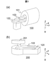
- MRI apparatus of 1st embodiment It is a general-view figure of the MRI apparatus of 1st embodiment, (a) is a horizontal magnetic field type MRI apparatus, (b) is a general-view figure of a vertical magnetic field type MRI apparatus. BRIEF DESCRIPTION OF THE DRAWINGS It is a block diagram of the MRI apparatus of 1st embodiment, (a) is a block diagram of the structure which provided the RF coil for transmission and the RF coil for reception separately, (b) is RF which uses both transmission and reception It is a block diagram of a structure provided with a coil. It is a schematic diagram of the balun of 1st embodiment.
- (A) And (b) is a figure for demonstrating the structure of the coaxial cable of 1st embodiment
- (c) is a figure for demonstrating the structure at the time of use. It is a figure for demonstrating operation
- (a) is an equivalent circuit schematic
- (b) is a figure which shows the frequency characteristic of an impedance. It is a figure for demonstrating operation
- (a) is a circuit diagram
- (b) is an equivalent circuit diagram when a resonant frequency is applied.
- (A), (c), (e) is a figure which shows the simulation result of the frequency characteristic of the impedance of the balun of 1st embodiment, (b), (d), (f) is the conventional balun.
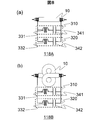
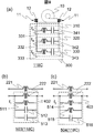
- (A), (b) is a schematic diagram of the modification of the balun of 1st embodiment. It is a figure for demonstrating operation
- (A) is a schematic diagram of the balun of 2nd embodiment, (b) is a circuit diagram of the balun of 2nd embodiment. It is the schematic diagram which attached the electromagnetic wave shield to the balun of 1st embodiment.
- (A) is a figure for demonstrating the structure of the conventional balun, (b) is a circuit diagram of the conventional balun, (c) is a figure which shows the frequency characteristic of the impedance of the conventional balun.
- FIG. 1 is an overview of the MRI apparatus of this embodiment.
- the z-axis direction of coordinate 9 is the static magnetic field direction.
- An MRI apparatus 100 shown in FIG. 1A includes a horizontal magnetic field type magnet 101.
- An MRI apparatus 200 shown in FIG. 1B includes a vertical magnetic field type magnet 201.
- These MRI apparatuses 100 and 200 include a table 120 on which the inspection object 103 is placed.
- This embodiment is applicable to both the MRI apparatus 100 including the horizontal magnetic field type magnet 101 and the MRI apparatus 200 including the vertical magnetic field type magnet 201.
- the MRI apparatus 100 having the horizontal magnetic field type magnet 101 will be described as an example.
- FIG. 2 is a block diagram showing a schematic configuration of the MRI apparatus 100.
- FIG. 2A is a block diagram in the case where a transmission RF coil that irradiates a high-frequency magnetic field and a reception RF coil that detects a nuclear magnetic resonance signal are separately provided.
- the MRI apparatus 100 includes a horizontal magnetic field type magnet 101, a gradient magnetic field coil 102 that generates a gradient magnetic field, a sequencer 104, an RF coil for transmission 116 that irradiates a test object 103 with a high-frequency magnetic field, and an inspection target 103.
- the gradient coil 102 is connected to a gradient power source 105.
- the transmission RF coil 116 is connected to the high-frequency power source 106 via the balun 118.
- the receiving RF coil 117 is connected to the receiver 108 via the balun 118.
- the sequencer 104 sends commands to the gradient magnetic field power source 105 and the high frequency power source 106 to generate a gradient magnetic field and a high frequency magnetic field, respectively.
- the high-frequency signal generated by the high-frequency power source 106 is applied to the inspection object 103 as a high-frequency magnetic field through the transmission RF coil 116.
- a magnetic resonance signal generated from the inspection object 103 by applying a high-frequency magnetic field is detected by the receiving RF coil 117, detected by the receiver 108, A / D converted, and sent to the computer 109.
- the magnetic resonance frequency used as a reference for detection by the receiver 108 is set by the sequencer 104.
- the computer 109 performs signal processing such as image reconstruction. As a result, an image is displayed on the display 110.
- the detected signals and measurement conditions are stored in the storage medium 111 as necessary.
- the sequencer 104 controls the operation of each device so that a gradient magnetic field and a high-frequency magnetic field are generated at a preprogrammed timing and intensity.
- the shim coil 112 When it is necessary to adjust the static magnetic field uniformity, the shim coil 112 is used.
- the transmission RF coil 116 and the reception RF coil 117 may be shared by a single transmission / reception RF coil 126 as shown in FIG. However, in this case, the transmission / reception RF coil is connected to the high-frequency power source 106 and the receiver 108 via a transmission / reception selector switch 127 that switches transmission / reception in time.
- a transmission RF coil 116 that generates a high-frequency magnetic field and a reception RF coil 117 that receives a signal from the inspection target 103 are provided separately will be described as an example.
- the RF coil for transmission 116 and the RF coil for reception 117 are represented by an RF coil when it is not necessary to distinguish between them.
- the transmission RF coil 116 and the high-frequency power source 106, and the reception RF coil 117 and the receiver 108 are connected by the coaxial cable 10, respectively.
- the balun 118 is formed with a part of the coaxial cable 10 as a part of the configuration.
- the characteristic impedance of the coaxial cable 10 to form the coaxial cable 10 and the balun 118 is connected to the balun 118, even when the unbalance occurs, common nuclear magnetic resonance frequency f 0 of the test object
- a balun 118 is provided that can provide high impedance to mode noise.
- FIG. 3 is a schematic diagram of a balun 118 using the coaxial cable 10 of the present embodiment.
- the balun 118 of this embodiment has a configuration in which the balun forming circuit 300 is connected in parallel to the outer conductors 12 at both ends of the coaxial cable 10 having a loop shape.
- the balun forming circuit 300 includes a first series resonance circuit 310 and a second series resonance circuit 320 connected in parallel.
- the first series resonance circuit 310 includes an inductor 331 and a capacitor 341 connected in series
- the second series resonance circuit 320 includes an inductor 332 and a capacitor 342 connected in series.
- a part of the coaxial cable 10 constituting the balun 118 of the present embodiment is obtained by extending the coaxial cable 10 so that the high-frequency power source 106, the transmission RF coil 116, the receiver 108, and the reception RF The coil 117 is connected. Accordingly, both ends of the coaxial cable 10 constituting the balun 118 are connected to the high-frequency power source 106 and the transmission RF coil 116 by the coaxial cable 10 or to the receiver 108 and the reception RF coil 117, respectively.
- the inductor 331 and the L A and L B respectively the inductance of the inductor 332, and C A and C B, respectively the capacitance of capacitor 341 and capacitor 342, a first series resonance circuit 310 and the second series resonance circuit 320 are represented as f A and f B , respectively.
- the nuclear magnetic resonance frequency f 0 of the measurement nuclide and the resonance frequencies f A and f B of the series resonance circuits 310 and 320 are adjusted so as to satisfy the following formula (2).
- the resonance frequencies f A and f B of the series resonance circuits 310 and 320 are the inductance L A , the capacitance C A , and the inductance L B of the inductor 331, the capacitor 341, the inductor 332, and the capacitor 342 constituting the respective series resonance circuit. and it is adjusted by adjusting the capacitance C B.
- the balun 118 can obtain a high impedance at the nuclear magnetic resonance frequency f 0 of the measurement nuclide.
- the resonance frequencies f A and f B of the series resonance circuits 310 and 320 are adjusted so as to satisfy the above formula (2), the balun 118 can obtain a high impedance at the nuclear magnetic resonance frequency f 0 of the measurement nuclide.
- FIG. 4A and FIG. 4B are diagrams for explaining the structure of the coaxial cable 10.
- the coaxial cable 10 of the present embodiment is a high-frequency transmission cable having a structure similar to that of the general coaxial cable described with reference to FIGS. 12A and 12B and having characteristic impedance.
- components having the same functions as those in FIGS. 12A and 12B are denoted by the same reference numerals.
- the coaxial cable 10 has a structure in which an inner conductor 11 and an outer conductor 12 are sandwiched between insulators (dielectrics) 13 and arranged on the same axis.
- the coaxial cable 10 exhibits excellent shielding characteristics because the outer conductor 12 is connected to the ground when in use.
- FIG. 4C is a diagram for explaining a configuration of the coaxial cable 10 in general use.
- a signal source 15 and a load 16 are connected to both ends of the inner conductor 11 of the coaxial cable 10.
- the other ends of the signal source 15 and the load 16 are connected to the ground 17.
- the outer conductor 12 of the coaxial cable 10 is also connected to the ground 17.
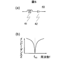
- FIG. 5A and FIG. 5B are diagrams for explaining the operation of a general series resonant circuit 40.
- the series resonance circuit 40 is formed by connecting an inductor 41 having an inductance L and a capacitor 42 having a capacitance C in series.
- the impedance Z at both ends of the series resonant circuit 40 is expressed by the following equation (3).
- FIG. 5B is a diagram for explaining the frequency characteristics of the series resonant circuit 40.
- the series resonant circuit 40 operates as inductive reactance in a frequency region (f RS ⁇ f) higher than the resonant frequency f RS .
- the impedance Z at this time is expressed by the following equation (4).
- the apparent inductance L ′ of the series resonant circuit 40 at this time is expressed by the following equation (5).
- the series resonance circuit 40 operates as a capacitive reactance in a frequency region (f ⁇ f RS ) lower than the resonance frequency f RS .
- the impedance Z at this time is expressed by the following equation (6).
- the apparent capacitance C ′ of the series resonant circuit 40 at this time is expressed by the following equation (7).
- the series resonance circuit 40 operates differently with the resonance frequency fRS as a boundary according to the frequency f of the voltage to be applied. That is, when the frequency f of the voltage applied is higher than the resonance frequency f RS operates as an inductive reactance, is lower than the resonance frequency f RS operates as a capacitive reactance.
- the operation and characteristics of the balun 118 of this embodiment will be described with reference to FIG.
- the resonance frequencies f A and f B of the first series resonance circuit 310 and the second series resonance circuit 320 constituting the balun 118 are adjusted so as to satisfy the above formula (2).
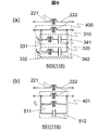
- FIG. 6A is a simplified circuit diagram 500 of the balun 118, and the inductances of the inner conductor 11 and the outer conductor 12 of the coaxial cable 10 are represented by lumped elements (inductors) 221 and 222, respectively, and are simplified. Is. As shown in the figure, the inner conductor 11, the inductance is represented by inductor 221 L S, the outer conductor 12, the inductance is represented by inductor 222 L G. As shown in the figure, the inductor 222, the first series resonance circuit 310, and the second series resonance circuit 320 constitute a parallel circuit 400 in series with the outer conductor 12 of the coaxial cable 10. That is, the balun 118 of this embodiment is represented as a parallel circuit 400 inserted in series with the outer conductor 12 of the coaxial cable 10.
- the balun 118 of this embodiment is represented as a parallel circuit 400 inserted in series with the outer conductor 12 of the coaxial cable 10.
- the resonance frequencies f A and f B of the series resonance circuits 310 and 320 of the balun 118 of the present embodiment are adjusted so as to satisfy the expression (2). Therefore, when the resonance frequency f RN is applied to the parallel circuit 400, the first series resonance circuit 310 operates as an inductive reactance (inductor), and the second series resonance circuit 320 functions as a capacitive reactance (capacitor). Operate.
- FIG. 6B shows a circuit diagram 501 of an equivalent circuit of the parallel circuit 400 when the resonance frequency f RN is applied to the parallel circuit 400.
- the first series resonance circuit 310 is represented by an inductor 511
- the second series resonance circuit 320 is represented by a capacitor 512.
- the inductance and capacitance at this time are L A ′ and C A ′, respectively.
- the equivalent circuit 501 is represented as a parallel resonant circuit 401 in which an inductor 222, an inductor 511, and a capacitor 512 are connected in parallel.
- the inductance L A ′ of the inductor 511 of the parallel resonant circuit 401 is expressed by the following formula (8) from the formula (5).
- the capacitance C B ′ of the capacitor 512 is expressed by the following formula (9) from the formula (7).
- f is the frequency of the voltage applied to the parallel resonant circuit 401.
- the resonance frequency f RN is affected by the inductance L A ′ and the capacitance C B ′ when f A and f B are set to a frequency higher and lower than f RN , respectively. It becomes easy. Furthermore, in the calculation formula (12) of the resonance frequency f RN , when f A and f B are set close to f RN , the inductance L A ′ and the capacitance C B ′ become dominant. Therefore, the resonance frequency f RN hardly changes even if the inductance L G of the outer conductor 12 of the coaxial cable 10 is changed.
- the outline of the adjustment is as follows. First, to determine the inductance L G of the inductor 222 that the outer conductor 12 of the coaxial cable 10 is made. Then, using the determined L G, from equation (13), equation (8), equation (9) and Equation (2), constituting a balun 118 (parallel circuit 400), the first series resonance circuit 310 The inductance L A of the inductor 331, the capacitance C A and the resonance frequency f A of the capacitor 341, the inductance L B of the inductor 341 of the second series resonance circuit 320, the capacitance C B of the capacitor 342, and the resonance frequency f B are determined.
- it is 128 MHz.
- L G of the inductor 222 that the outer conductor 12 of the coaxial cable 10 is made.
- the inductance of a typical 3T MRI apparatus balun inductor is 100 nH.
- size of an inductance is not limited to this. From equation (13), in order to increase the impedance Z RN of the parallel circuit 400 is preferably L G is a great value. However, since the required impedance differs depending on the application, it is appropriately determined according to the application.
- the inductance L A and the capacitance C B of the inductor 331 of the first series resonance circuit 310 and the capacitor 342 of the second series resonance circuit 320 are determined. From equation (13), in order to increase the impedance Z RN of the parallel circuit 400 (parallel resonance circuit 401), the inductance L A ′ of the inductor 511 is preferably a large value. Similarly, in order to increase the impedance Z RN of the parallel circuit 400 (parallel resonant circuit 401), the capacitance C B ′ of the capacitor 512 is preferably small. In other words, equation (8), large inductance L A of the inductor 331 from the equation (9), the capacitance C B of the capacitor 342 is preferably small.
- an inductor having an inductance in the range of 10 nH to 200 nH, a capacitor having a capacitance in the range of 1 pF to 100 pF, and Select is preferable.
- the inductance L A of the inductor 331 is 200 nH
- the capacitance C B of the capacitor 342 is set to 7 pF.
- the inductor 331 and the capacitor 342 are not limited to the above range. Any element having a value in a feasible range may be used.
- the resonance frequencies f A and f B are the nuclear magnetic resonance of the measurement nuclide. it is desirable close to the frequency f 0.
- f A and f B are separated from f 0 according to the equation (13). Based on the above, it is desirable that f 0 , f A , and f B satisfy the following expressions (14) and (15) in order to obtain a higher effect than the conventional system.
- each value is determined so that f A and f B obtained from Expression (8), Expression (9), and Expression (12) satisfy Expression (14) and Expression (15).
- f A is between 102 MHz and 120 MHz
- Expression (14) and Expression (15) are satisfied.
- f A is set to 110 MHz.
- the resonance frequency f a 110 MHz
- the resonance frequency f B of the second series resonance circuit 320 the capacitance C a of the capacitor 341
- an inductance L B of the inductor 332 (8)
- equation (9) the formula ( 12).
- f B 139 MHz
- C A 10.5 pF
- L B 186 nH.
- the balun 118 of the present embodiment is capable of removing common mode noise with high accuracy even when the characteristic impedance of the coaxial cable 10 is unbalanced and the resonance frequency is difficult to shift from the initial adjustment value. is there.
- the balun 118 having such an effect can be realized with a simple configuration and an easily available element. Therefore, a high-performance RF coil can be realized at low cost.
- FIG. 7 is a diagram showing the result of the simulation. Effects caused by the imbalance of the characteristic impedance, the equivalent can be represented by a change in the inductance L G of the inductor 222 by the outer conductor 12 of the coaxial cable 10 to form a loop. By changing the inductance L G in the simulation, and reproduces the effects caused by the imbalance of the characteristic impedance.
- FIGS. 7 (c) and 7 FIG. 7 (d) the respective balun 118 of this embodiment and the conventional method balun 20, the influence caused by the imbalance of the characteristic impedance, increasing the inductance L G of the coaxial cable 10 is 10%
- the frequency characteristic of the impedance Z in the case of the above is shown.
- the resonance peak of the balun 118 is shifted slightly (0.2 MHz) to a low frequency.
- the conventional balun 20 as shown in FIG. 7D, the resonance peak of the balun 20 is greatly shifted to a low frequency (6.0 MHz).
- the inductance L G of the coaxial cable 10 is affected by the imbalance between the characteristic impedances of the balun 118 of the present embodiment and the balun 20 of the conventional method.
- the frequency characteristic of the impedance Z when the value of is reduced by 10% is shown.
- the resonance peak of the balun 118 is shifted to a high frequency slightly (0.2 MHz).
- the conventional balun 20 as shown in FIG. 7 (e), the resonance peak of the balun was greatly shifted to a high frequency (6.9 MHz).
- the present embodiment in the formula is a formula for calculating the f RN an equation (12) representing the resonant frequency of the balun 118 (12), it is evident from the fact that 'the L C' L a is the dominant.
- the balun 118 of this embodiment provides a high impedance to common mode noise in the adjusted frequency f 0.
- the first series resonance circuit 310 and the second series resonance circuit 320 constituting the balun 118 have one of the resonance frequencies f A and f B set to a frequency lower than the frequency f 0 and the other set to f 0. It has been adjusted to a higher frequency. Therefore, even if a change in the inductance L G COAX 10 constituting a balun 118 for any reason arises, the resonance frequency f RN balun 118 hardly changes. Thus, the balun 118 of this embodiment can maintain high impedance at the frequency f 0 that is adjusted.
- the balun 118 of this embodiment an imbalance occurs in the characteristic impedance of the coaxial cable 10, even if a change in the inductance L G occurs, higher than the adjusted common mode noise frequency f 0 Impedance can be provided. Therefore, according to the present embodiment, even when the characteristic impedance of the coaxial cable 10 is unbalanced, the common mode noise can be effectively removed and the performance of the RF coil can be improved.
- the resonance frequency f RN balun 118 of this embodiment is not susceptible to inductance L G of the outer conductor 12 of the coaxial cable 10 that is affected the most external factors. Therefore, once the resonance frequency f RN of the balun 118 is adjusted to the nuclear magnetic resonance frequency f 0 of the measurement nuclide, the coaxial cable 10 connected to the balun 118, the installation method, and the positional relationship are hardly affected by external factors. . Therefore, the balun 118 of this embodiment can maintain high impedance at the nuclear magnetic resonance frequency f 0 of the measurement nuclide.
- the characteristic impedance of the coaxial cable 10 forming the balun is unbalanced, a high impedance can be maintained, so that when the coaxial cable 10 constituting the balun 118 is used, There are no restrictions on placement. That is, there is no need to consider that the characteristic impedance is unbalanced, and the degree of freedom during use is increased.
- the balun 118 of the present embodiment can maintain a high impedance at the nuclear magnetic resonance frequency f 0 of the measurement nuclide, so that the number of baluns can be reduced.
- unbalance occurs in the characteristic impedance of the coaxial cable 10, as the inductance L G of the outer conductor 12 of the coaxial cable 10 is changed, it can be maintained high impedance. Therefore, unlike the conventional balun 20, it is not necessary to connect the baluns 20 in series to synthesize impedance. For this reason, it is possible to reduce the weight, volume and cost of the apparatus.
- the frequency f RN at which the balun 118 intentionally removes the common mode noise may be shifted by several MHz from the nuclear magnetic resonance frequency f 0 of the measurement nuclide. is there. Even in such a case, by using the balun 118 of this embodiment, it is possible to prevent the resonance frequency of the balun 118 and the RF coil from matching due to an unexpected frequency shift of the balun 118. For this reason, the performance of the RF coil can be improved.
- the resonance frequency of the balun 118 is adjusted to the nuclear magnetic resonance frequency of the hydrogen nucleus in the 3T MRI apparatus.
- the resonance frequency to be adjusted is not limited to this.
- it may be the nuclear magnetic resonance frequency of a hydrogen nucleus in an MRI apparatus having a static magnetic field strength of 1.5T or 7T.
- it may be a nuclear magnetic resonance frequency such as fluorine or carbon nucleus.
- the resonance frequency of the balun used in the MRI apparatus is less likely to fluctuate with a simple configuration. Therefore, even if there is an imbalance in the characteristic impedance of the coaxial cable connected to the balun or the coaxial cable forming the balun, it has a high impedance against the common mode noise of the nuclear magnetic resonance frequency f 0 of the measurement nuclide. Since it can be provided, common mode noise can be removed. Therefore, the performance of the RF coil is improved.
- the shape of the balun 118 of this embodiment is not restricted to the said shape.
- the electrical circuit diagram may be equivalent to the circuit diagram 500.
- the shape of the coaxial cable 10 of the balun 118 of this embodiment may be a straight line.
- FIG. 8A shows a linear balun 118A which is a modification of the balun 118 of the present embodiment.
- the linear balun 118A has a shape in which two series resonant circuits 310 and 320 are connected in parallel to a straight coaxial cable 10 having no special shape.
- the configuration of the two series resonant circuits 310 and 320 is the same as that of the balun 118.
- the shape of the coaxial cable 10 may be an 8-shaped shape.
- FIG. 8B shows an 8-shaped balun 118B, which is a modification of the balun 118 of the present embodiment.
- the 8-shaped balun 118B has a shape in which two series resonant circuits 310 and 320 are connected in parallel to the coaxial cable 10 formed in an 8-shaped shape.
- the configuration of the two series resonant circuits 310 and 320 is the same as that of the balun 118.
- the circuit configuration of the straight baluns 118 ⁇ / b> A and the 8-shaped balun 118 ⁇ / b> B can be represented by the same circuit diagram 500 as the balun 118. Therefore, these baluns 118A and 118B have the same circuit configuration and operation principle as the balun 118 of the above embodiment. For this reason, the linear balun 118A and the figure-shaped balun 118B have a high impedance with respect to the adjusted common mode noise of the frequency f 0 even when the characteristic impedance of the coaxial cable 10 is unbalanced. Can be provided.
- the shape of the coaxial cable 10 and the balun 118 are different, the value of the inductance L G by inductor inductance L S and Dogaibu conductor 12 by an inductor with an inner conductor 11 of the coaxial cable 10 is made to make changes. Therefore, according to the value of the inductance L G, determining f A, f B, L B , and C A.
- the linear balun 118A has a linear shape
- the balun can be formed in a space-saving manner as shown in FIG.
- the figure-shaped balun 118B has a shape in which two loops generate magnetic fields in opposite directions as shown in FIG. 8B
- the coaxial cable 10 of the balun 118B is The generated magnetic field can be canceled.
- the disturbance of the magnetic field can be reduced, the performance of the RF coil is improved.
- the balun that removes common mode noise of one frequency has been described as an example.
- the frequency of the common mode noise that can be removed by the balun to which the present invention is applicable is not limited to one.
- it may be a balun capable of removing common mode noise at two different frequencies (for example, magnetic resonance frequencies of hydrogen and fluorine).
- FIG. 9 shows a balun 118C, which is a modification of the balun 118 of the present embodiment and can remove common mode noise of two different frequencies.
- the balun 118C of the present modification includes a third series resonant circuit in which an inductor (L C ) 333 and a capacitor (C C ) 343 are connected in series in addition to the configuration of the balun 118 of the present embodiment.
- 330 is connected to the second resonant circuit 320.
- the resonance frequencies (f A , f B , f C ) of the first, second, and third series resonance circuits 310, 320, and 330 are determined by the balun 118 C according to the magnetic resonance frequencies of the first and second elements. It is adjusted so as to resonate at the first and second resonance frequencies (f 1 , f 2 ) and to show a high impedance. Specifically, it adjusts so that the following formula
- balun 118C The operation and characteristics of the balun 118C of this modification will be described with reference to circuit diagrams shown in FIGS. 9 (a), (b), and (c).
- the balun 118C is represented by a circuit in which three series resonance circuits 310, 320, and 330 including inductors and capacitors are connected in parallel. Resonant frequencies of the respective series resonant circuits 310, 320, and 330 are f A , f B , and f C.
- the first series resonance circuit 310 since it is adjusted to satisfy the equation (16), the first voltage of the resonance frequency f 1 is applied, the first series resonance circuit 310 operates as an inductive reactance And can be regarded as an inductor 511 (L A ′′).
- the second series resonance circuit 320 and the third series resonance circuit 330 operate as capacitive reactances and can be regarded as capacitors 512 and 513 (C B ′′, C C ′′).
- the balun 118C of the present modified example is represented as an inductor 222,511, the parallel resonant circuit 402 connected to the capacitor 512 and 513 in parallel shown in Figure 9 (b).
- the balun 118C exhibits a high impedance at the first resonance frequency f 1, to remove common mode noise.
- the relationship between the values of the capacitor capacitors 512 and 513, C B ′′, C C ′′ is as shown in the following formula (17) from the formula (10).
- the balun 118C of this modified example since it is adjusted to satisfy the equation (16), when the voltage of the second resonance frequency f 2 is applied, the first series resonance circuit 310, the second The series resonant circuit 320 operates as an inductive reactance and can be regarded as inductors 514 and 515 (L A ′′, L B ′′).
- the third series resonant circuit 330 operates as a capacitive reactance and can be regarded as a capacitor 516 (C C ′′).
- the balun 118C of this modified example the inductor 222,511 shown in FIG. 9 (c), expressed as a parallel resonant circuit 403 connected to the capacitor 514 and 515 in parallel.
- the balun 118C exhibits a high impedance at the first resonant frequency f 2, to remove common mode noise.
- the second resonance frequency f 2 and the values L G , L A ′′ of the inductors 222, 514, 515 constituting the parallel resonance circuit 402.
- the relationship between L B ′′ and the value of each capacitor capacitor 516, C C ′′ is as shown in the following equation (18) from equation (10).
- the balun 118C of the present modified example adjusts the values of f A , f B , f C , and the constituent inductors and capacitors so as to satisfy the expressions (16), (17), and (18). By doing so, it resonates at the magnetic resonance frequencies (f 1 , f 2 ) of the two elements and exhibits high impedance. Therefore, the common mode noise of these magnetic resonance frequencies f 1 and f 2 can be removed. Further, the same effects as those of the balun 118 of the present embodiment can be obtained except for the number of common mode noise frequencies that can be removed.
- the two different frequencies are the magnetic resonance frequencies of hydrogen and fluorine, but the combination is not limited to this.
- fluorine and helium ( 3 He), phosphorus ( 31 P), lithium ( 7 Li), or the like may be used.
- the combination of nuclei is not limited to this.
- FIG. 10A is a diagram showing the shape of the balun 118-2 of the present embodiment.
- the balun forming circuit 300-2 of this embodiment includes a first series resonance circuit 310 and a second series resonance circuit 320 connected in parallel, and a conductor 350 connected in parallel thereto.
- the balun forming circuit 300-2 in which the two series resonant circuits 310 and 320 are connected in parallel and the coaxial cable 10 are not directly physically connected.
- the conductor 350 is brought into close contact with the outer conductor 12 of the coaxial cable 10 and magnetically coupled.
- FIG. 10B is a circuit diagram 500-2 of the balun 118-2 of the present embodiment, in which the inductances of the inner conductor 11 and the outer conductor 12 of the coaxial cable 10 are concentrated elements (inductors) 221 and 222, respectively. Further, the inductance due to the conductor 350 is represented by a lumped element (inductor) 351 and simplified. As in the first embodiment, the inductance of the inductor 221 is L S , the inductance of the inductor 222 is L G , and the inductance of the inductor 351 is L C.
- the balun 118-2 of this embodiment since the magnetic coupling 990 is generated between the inductor 222 and the inductor 351, the inductor 222 and the inductor 351 are electromagnetically inductively connected. Therefore, in the balun 118-2 of this embodiment, the balun forming circuit 300-2 and the coaxial cable 10 are not directly physically connected by a conductor, but are electromagnetically inductively connected.
- the balun 118-2 also has an electrical equivalent circuit equivalent to the circuit diagram 500. However, since the balun 118 of the first embodiment bonding method is different, the inductance L G of the inductor 222 must consider the mutual inductance.
- the inductances L A and L B and the capacitances C A and C B of each component are determined so that a high impedance is obtained at the nuclear magnetic resonance frequency f 0 of the detection target nuclide.
- the balun 118-2 of this embodiment the nuclear magnetic resonance frequency f 0 of the measurement nuclide can be given a high impedance to common mode noise. Also, one of the resonance frequency f B of the first resonant frequency f A and the second series resonance circuit 320 of the series resonant circuit 310 which constitutes a balun 118-2, a frequency lower than the nuclear magnetic resonance frequency f 0 , to set the other with a frequency higher than f 0, even if a change in the inductance L G cOAX 10 is caused for some reason, the resonance frequency f RN balun 118-2 of the present embodiment hardly changes do not do.
- the balun 118-2 of the present embodiment can maintain the operation and the resonance frequency of the frequency f 0 that is adjusted. Therefore, even when the unbalance occurs in the characteristic impedance of the coaxial cable 10, it is possible to provide a high impedance to the adjusted common mode noise frequency f 0. As described above, the balun 118-2 of the present embodiment can provide a high-performance RF coil as in the first embodiment.
- balun 118-2 of the present embodiment does not require direct physical connection to the coaxial cable 10, the same effects as those of the first embodiment can be realized with a simpler configuration. Furthermore, since a direct physical connection is not required, the MRI examination operator can use the balun 118-2 as necessary. Therefore, the degree of freedom in using the balun 118-2 is increased, and high-precision inspection is possible.
- the coaxial cable 10 forming the balun may be covered with the radio wave shield 600.
- FIG. 11 is a view for explaining an example (118 ⁇ / b> D) when the balun 118 of the first embodiment is covered with the radio wave shield 600. As shown in the figure, the balun 118D is entirely covered with the radio wave shield 600. The radio wave shield 600 is connected to the ground 17.
- the inductors in the balun 118D are an inductor made by the coaxial cable 10, an inductor 331 of the first series resonance circuit 310, and an inductor 332 of the second series resonance circuit 320.
- the balun 118D covered with the radio wave shield 600 is further less susceptible to fluctuations in the resonance frequency than the balun 118 having the configuration described in the first embodiment. Accordingly, a high impedance can be given to the common mode noise at a desired nuclear magnetic resonance frequency, and even when the characteristic impedance of the coaxial cable 10 is unbalanced, the resonance peak moves less, Higher impedance can be maintained.
- the disturbance of the magnetic field generated by the coaxial cable 10 and the inductors 331 and 332 can be suppressed, the influence on other baluns and RF coils can be suppressed. That is, according to this embodiment, it is possible to reduce the external influence and reduce the loss due to magnetic coupling.
- the case where the measurement nuclide is one type (hydrogen nucleus) and the balun of each of the above embodiments and modifications is used as an example for an RF coil that acquires only a magnetic resonance signal of one frequency is taken as an example.
- the baluns of the above embodiments and modifications may be used for, for example, a double-tuned RF coil that can acquire magnetic resonance signals of two nuclei with one RF coil. Of course, it is not limited to this.
- the resonance frequency f 0 of the balun the relationship between the resonance frequency f B of the resonance frequency f A and the second series resonance circuit 320 of the first series resonance circuit 310, the formula ( Although a case in which as shown by 2) are described as an example, the resonant frequency f a and the resonance frequency f B may be reversed. That is, a configuration that satisfies the following expression (19) may be used. That is, f A , f B , and f 0 are different frequencies, and any one of f A and f B may be a frequency lower than f 0 and the other may be a frequency higher than f 0 .
- the balun forming circuit includes two series resonant circuits each having a different resonance frequency
- the circuit configuration of the balun forming circuit is limited to this. Absent. It may be configured to include two or more series resonant circuits having at least two different resonant frequencies. In this case, the resonance frequency of each series resonance circuit is adjusted so that the resonance frequency of the baluns of the above embodiments and modifications is between the resonance frequencies of any of the series resonance circuits.
- At least one of the resonance frequencies of each series resonance circuit is a frequency lower than f 0 . at least one so as to be a frequency higher than f 0, adjusting the resonance frequency of the nuclei series resonant circuit.
- baluns of the above embodiments and modifications may be directly connected to the feeding point of the RF coil.
- common mode noise flowing into the RF coil can be more reliably removed.
- the performance of the RF coil can be improved.
- baluns of the above embodiments and modifications may be used in combination with the conventional balun 20.
- the performance of the RF coil can be improved.
- the baluns of the above embodiments and modifications can be used in a multi-channel RF coil system.
- the multi-channel RF coil system it is possible to prevent the balun's resonance frequency from being shifted due to the coupling between the balun and the balun and the coaxial cable 10. For this reason, even in a multi-channel RF coil system, the performance of the RF coil can be improved by using the baluns of the above embodiments and modifications.
- baluns there is one balun between the high-frequency power source 106 and the transmission RF coil 116 or between the receiver 108 and the reception RF coil 117 in the MRI apparatus 100 has been shown. There may be more than one balun.
- the balun is formed using the general coaxial cable 10 having the configuration shown in FIG. 4
- the applicable coaxial cable is not limited to the coaxial cable 10.
- a coaxial cable called a “semi-rigid cable” in which the outer conductor is a small-diameter copper pipe may be used.
- it is not limited to this.
Landscapes
- Physics & Mathematics (AREA)
- Condensed Matter Physics & Semiconductors (AREA)
- General Physics & Mathematics (AREA)
- Magnetic Resonance Imaging Apparatus (AREA)
Abstract
Description

以下、本発明を適用する第一の実施形態について説明する。以下、本発明の実施形態を説明するための全図において、同一機能を有するものは同一符号を付し、その繰り返しの説明は省略する。












および各キャパシタキャパシタ512,513の値、CB’’、CC’’との関係は、式(10)より、以下の式(17)とおりとなる。

LB’’ および各キャパシタキャパシタ516の値、CC’’の関係は、式(10)より、以下の式(18)のとおりとなる。

次に本発明を適用する第二の実施形態について説明する。本実施形態のMRI装置は基本的に第一の実施形態と同様である。本実施形態では、二つの直列共振回路310、320を並列に接続したバラン形成回路と、同軸ケーブル10とを直接物理的に接続する代わりに、磁気結合を用いて、磁気的に誘導接続する。以下、第一の実施形態と異なる構成に主眼をおいて説明する。

Claims (15)
- 同軸ケーブルに流れるコモンモードノイズを除去するバランであって、
前記同軸ケーブルの一部と、
前記同軸ケーブルの一部の外部導体に並列接続される並列回路と、を備え、
前記並列回路は、それぞれ並列に接続される複数の直列共振回路を備え、
前記複数の直列共振回路は、それぞれ、直列に接続されるキャパシタとインダクタとを備え、当該キャパシタのキャパシタンスおよび当該インダクタのインダクタンスによりそれぞれの共振周波数が調整可能であり、
前記複数の直列共振回路の共振周波数は、少なくとも1つが、当該バランが前記コモンモードノイズを除去する周波数より低い周波数に、少なくとも1つが、当該バランが前記コモンモードノイズを除去する周波数より高い周波数になるよう調整されていること
を特徴とするバラン。 - 請求項1記載のバランであって、
前記複数の直列共振回路は、第一の直列共振回路と第二の直列共振回路の2つであり、
前記第一の直列共振回路の共振周波数である第一の共振周波数と、前記第二の直列共振回路の共振周波数である第二の共振周波数とは、いずれか一方が、当該バランが前記コモンモードノイズを除去する周波数より低い周波数に、他方が、当該バランが前記コモンモードノイズを除去する周波数より高い周波数になるよう調整されていること
を特徴とするバラン。 - 請求項2記載のバランであって、
前記第一の共振周波数および前記第二の共振周波数の中で、前記バランが前記コモンモードノイズを除去する周波数より低い周波数となるよう調整されている共振周波数は、前記バランが前記コモンモードノイズを除去する周波数の70%から95%の間となるよう調整されていること
を特徴とするバラン。 - 請求項2記載のバランであって、
前記第一の共振周波数および前記第二の共振周波数の中で、前記バランが前記コモンモードノイズを除去する周波数より高く調整されている共振周波数は、前記バランが前記コモンモードノイズを除去する周波数の105%から130%の間となるよう調整されていること
を特徴とするバラン。 - 請求項1記載のバランであって、
前記複数の直列共振回路は、第一の直列共振回路と第二の直列共振回路と第三の直列共振回路の3つであり、
前記第一直列共振回路の共振周波数fAと前記第二直列共振回路の共振周波数fBと前記第一直列共振回路の共振周波数fCと当該バランが前記コモンモードノイズを除去する第一の周波数f1と当該バランが前記コモンモードノイズを除去する第二の周波数f2(>f1)とが、fA<f1<fB<f2<fCの関係を満たすように調整されていること
を特徴とするバラン。 - 請求項1記載のバランであって、
前記同軸ケーブルの一部は、ループ形状を有すること
を特徴とするバラン。 - 請求項1記載のバランであって、
前記同軸ケーブルの一部は、直線状であること
を特徴とするバラン。 - 請求項1記載のバランであって、
前記同軸ケーブルの一部は、8の字型形状を有すること
を特徴とするバラン。 - 請求項1記載のバランであって、
前記並列回路は、磁気結合手段を備え、前記同軸ケーブルの一部の外部導体と磁気的に接続されること
を特徴とするバラン。 - 請求項1記載のバランであって、
前記同軸ケーブルの一部と、前記並列回路とに、電波シールドが施されていること
を特徴とするバラン。 - バランを形成する同軸ケーブルであって、
当該同軸ケーブルの一部の外部導体に接続される並列回路を備え、
前記並列回路は、それぞれ並列に接続される複数の直列共振回路でを備え、
前記複数の直列共振回路は、それぞれ、直列に接続されるキャパシタとインダクタとを備え、当該キャパシタのキャパシタンスおよび当該インダクタのインダクタンスによりそれぞれの共振周波数が調整可能であり、
前記複数の直列共振回路の共振周波数は、少なくとも1つが、当該バランが前記コモンモードノイズを除去する周波数より低い周波数に、少なくとも1つが、当該バランが前記コモンモードノイズを除去する周波数より高い周波数になるよう調整されていること
を特徴とする同軸ケーブル。 - 静磁場を形成する静磁場形成手段と、傾斜磁場を形成する傾斜磁場形成手段と、高周波磁場を形成する高周波磁場形成手段と、前記高周波磁場を検査対象に印加するとともに検査対象からの磁気共鳴信号を受信する送受信コイルと、前記送受信コイルで受信した磁気共鳴信号を処理する信号処理手段と、前記高周波磁場を検査対象に印加する時は、前記高周波磁場形成手段と前記送受信コイルとを接続し、前記送受信コイルで受信した磁気共鳴信号を処理する時は、前記送受信コイルと前記信号処理手段とを接続する送受信切替手段と、前記傾斜磁場形成手段、前記高周波磁場形成手段および前記信号処理手段を制御する制御手段と、を備える磁気共鳴撮像装置であって、
前記送受信コイルと前記送受信切替手段とは同軸ケーブルで接続され、
前記同軸ケーブルはバランを備え、
前記バランは、請求項1記載のバランであり、前記同軸ケーブルに接続されていること
を特徴とする磁気共鳴撮像装置。 - 静磁場を形成する静磁場形成手段と、傾斜磁場を形成する傾斜磁場形成手段と、高周波磁場を形成する高周波磁場形成手段と、前記高周波磁場を検査対象に印加する送信コイルと、検査対象からの磁気共鳴信号を受信する受信コイルと、前記受信コイルで受信した磁気共鳴信号を処理する信号処理手段と、前記傾斜磁場形成手段、前記高周波磁場形成手段および前記信号処理手段を制御する制御手段と、を備える磁気共鳴撮像装置であって、
前記高周波磁場形成手段で形成した高周波磁場を前記送信コイルに送信する第一の同軸ケーブルと、
前記受信コイルで受信した磁気共鳴信号を前記信号処理手段に送信する第二の同軸ケーブルと、を備え、
前記第一の同軸ケーブルと前記第二の同軸ケーブルとはそれぞれバランを備え、
前記バランは、請求項1記載のバランであり、前記第一の同軸ケーブルおよび前記第二の同軸ケーブルに接続されていること
を特徴とする磁気共鳴撮像装置。 - 請求項12記載の磁気共鳴撮像装置であって、
前記同軸ケーブルは、前記バランを複数備えること
を特徴とする磁気共鳴撮像装置。 - 請求項13記載の磁気共鳴撮像装置であって、
前記第一の同軸ケーブルおよび前記第二の同軸ケーブルの少なくとも一方は、前記バランを複数備えること
を特徴とする磁気共鳴撮像装置。
Priority Applications (2)
| Application Number | Priority Date | Filing Date | Title |
|---|---|---|---|
| US13/142,439 US8803526B2 (en) | 2009-02-04 | 2010-01-28 | Balun and magnetic resonance imaging apparatus |
| JP2010549448A JP5220872B2 (ja) | 2009-02-04 | 2010-01-28 | バランおよび磁気共鳴撮像装置 |
Applications Claiming Priority (2)
| Application Number | Priority Date | Filing Date | Title |
|---|---|---|---|
| JP2009023491 | 2009-02-04 | ||
| JP2009-023491 | 2009-02-04 |
Publications (1)
| Publication Number | Publication Date |
|---|---|
| WO2010090129A1 true WO2010090129A1 (ja) | 2010-08-12 |
Family
ID=42542027
Family Applications (1)
| Application Number | Title | Priority Date | Filing Date |
|---|---|---|---|
| PCT/JP2010/051144 Ceased WO2010090129A1 (ja) | 2009-02-04 | 2010-01-28 | バランおよび磁気共鳴撮像装置 |
Country Status (3)
| Country | Link |
|---|---|
| US (1) | US8803526B2 (ja) |
| JP (1) | JP5220872B2 (ja) |
| WO (1) | WO2010090129A1 (ja) |
Cited By (4)
| Publication number | Priority date | Publication date | Assignee | Title |
|---|---|---|---|---|
| JP2015501069A (ja) * | 2011-11-30 | 2015-01-08 | ゼネラル・エレクトリック・カンパニイ | 微小電気機械スイッチおよびその関連方法 |
| JP2018201868A (ja) * | 2017-06-05 | 2018-12-27 | キヤノンメディカルシステムズ株式会社 | 傾斜磁場コイル |
| JP2019532740A (ja) * | 2016-10-24 | 2019-11-14 | コーニンクレッカ フィリップス エヌ ヴェKoninklijke Philips N.V. | 磁気共鳴イメージング(mri)システムで使用するためのバラン及びバランを使用したmriシステム |
| US20210215778A1 (en) * | 2016-09-29 | 2021-07-15 | Hyperfine Research, Inc. | Radio frequency coil tuning methods and apparatus |
Families Citing this family (12)
| Publication number | Priority date | Publication date | Assignee | Title |
|---|---|---|---|---|
| US9685704B2 (en) * | 2012-01-18 | 2017-06-20 | Michael Bank | Surface antenna with a single radiation element |
| CN103378391B (zh) * | 2012-04-27 | 2016-08-31 | Ge医疗系统环球技术有限公司 | 一种巴伦 |
| US9093978B2 (en) * | 2013-04-29 | 2015-07-28 | Qualcomm Incorporated | Multi-loop transformer having wideband frequency applications |
| US10234518B2 (en) | 2014-02-21 | 2019-03-19 | Children's Hospital Medical Center | Loop coil with integrated balun for MR applications |
| US10031195B2 (en) | 2014-07-30 | 2018-07-24 | Children's Hospital Medical Center | Detector grid arrays for MR imaging |
| US10816621B2 (en) | 2014-07-30 | 2020-10-27 | Children's Hospital Medical Center | Magnetic resonance signal detector grid assemblies for magnetic resonance imaging |
| US10353028B2 (en) * | 2015-11-20 | 2019-07-16 | Quality Electrodynamics, Llc | Current magnitude control at different sections in one coil |
| US10408897B2 (en) * | 2016-06-30 | 2019-09-10 | Canon Medical Systems Corporation | Magnetic resonance imaging apparatus |
| DE102016214441B3 (de) * | 2016-08-04 | 2017-11-30 | Bruker Biospin Gmbh | Hochfrequenz-Interface-Schaltkreis, Hochfrequenzsystem und Magnetresonanzapparatur mit einem Hochfrequenz-Interface-Schaltkreis |
| WO2019243274A1 (en) * | 2018-06-17 | 2019-12-26 | Skope Magnetic Resonance Technologies Ag | Sheath wave barrier for magnetic resonance (mr) applications |
| CN113036382A (zh) * | 2021-04-27 | 2021-06-25 | 上海辰光医疗科技股份有限公司 | 一种用于磁共振射频线圈的新型共模抑制巴伦结构 |
| JP2024126931A (ja) * | 2023-03-08 | 2024-09-20 | 富士フイルム株式会社 | コイルユニット及びそれを用いた磁気共鳴撮像装置 |
Citations (2)
| Publication number | Priority date | Publication date | Assignee | Title |
|---|---|---|---|---|
| JP2007517570A (ja) * | 2004-01-14 | 2007-07-05 | コーニンクレッカ フィリップス エレクトロニクス エヌ ヴィ | 電気導電性調整要素を選択的に挿入することにより調整されるrfトラップ |
| JP2008295737A (ja) * | 2007-05-31 | 2008-12-11 | Hitachi Ltd | 磁場コイル及び磁気共鳴撮像装置 |
Family Cites Families (3)
| Publication number | Priority date | Publication date | Assignee | Title |
|---|---|---|---|---|
| US4682125A (en) * | 1986-02-10 | 1987-07-21 | The Regents Of The University Of California | RF coil coupling for MRI with tuned RF rejection circuit using coax shield choke |
| US5371466A (en) * | 1992-07-29 | 1994-12-06 | The Regents Of The University Of California | MRI RF ground breaker assembly |
| US6320385B1 (en) * | 1999-09-17 | 2001-11-20 | Picker International, Inc. | Multi-channel balun for magnetic resonance apparatus |
-
2010
- 2010-01-28 US US13/142,439 patent/US8803526B2/en active Active
- 2010-01-28 JP JP2010549448A patent/JP5220872B2/ja active Active
- 2010-01-28 WO PCT/JP2010/051144 patent/WO2010090129A1/ja not_active Ceased
Patent Citations (2)
| Publication number | Priority date | Publication date | Assignee | Title |
|---|---|---|---|---|
| JP2007517570A (ja) * | 2004-01-14 | 2007-07-05 | コーニンクレッカ フィリップス エレクトロニクス エヌ ヴィ | 電気導電性調整要素を選択的に挿入することにより調整されるrfトラップ |
| JP2008295737A (ja) * | 2007-05-31 | 2008-12-11 | Hitachi Ltd | 磁場コイル及び磁気共鳴撮像装置 |
Non-Patent Citations (1)
| Title |
|---|
| P.SIPILA ET AL.: "A magnetic field monitoring add-on toolkit based on transmit-receive NMR probes", PROC. INTL. SOC. MAG. RESON. MED., 2008, pages 680 * |
Cited By (7)
| Publication number | Priority date | Publication date | Assignee | Title |
|---|---|---|---|---|
| JP2015501069A (ja) * | 2011-11-30 | 2015-01-08 | ゼネラル・エレクトリック・カンパニイ | 微小電気機械スイッチおよびその関連方法 |
| US20210215778A1 (en) * | 2016-09-29 | 2021-07-15 | Hyperfine Research, Inc. | Radio frequency coil tuning methods and apparatus |
| US11714147B2 (en) * | 2016-09-29 | 2023-08-01 | Hyperfine Operations, Inc. | Radio frequency coil tuning methods and apparatus |
| JP2019532740A (ja) * | 2016-10-24 | 2019-11-14 | コーニンクレッカ フィリップス エヌ ヴェKoninklijke Philips N.V. | 磁気共鳴イメージング(mri)システムで使用するためのバラン及びバランを使用したmriシステム |
| JP7004709B2 (ja) | 2016-10-24 | 2022-01-21 | コーニンクレッカ フィリップス エヌ ヴェ | 磁気共鳴イメージング(mri)システムで使用するためのバラン及びバランを使用したmriシステム |
| JP2018201868A (ja) * | 2017-06-05 | 2018-12-27 | キヤノンメディカルシステムズ株式会社 | 傾斜磁場コイル |
| JP7005179B2 (ja) | 2017-06-05 | 2022-01-21 | キヤノンメディカルシステムズ株式会社 | 傾斜磁場コイル |
Also Published As
| Publication number | Publication date |
|---|---|
| US8803526B2 (en) | 2014-08-12 |
| JPWO2010090129A1 (ja) | 2012-08-09 |
| JP5220872B2 (ja) | 2013-06-26 |
| US20110267062A1 (en) | 2011-11-03 |
Similar Documents
| Publication | Publication Date | Title |
|---|---|---|
| JP5220872B2 (ja) | バランおよび磁気共鳴撮像装置 | |
| JP6145115B2 (ja) | Mr画像生成のためのマルチ共振t/rアンテナ | |
| US8742759B2 (en) | High-frequency coil and magnetic resonance imaging device | |
| JP5705884B2 (ja) | Rfコイル及び磁気共鳴撮像装置 | |
| US7573432B1 (en) | MRI antenna | |
| US8193810B2 (en) | MRI apparatus with RF surface coil having at least three resonance frequencies | |
| CN103026251B (zh) | Mri rf线圈阵列的多个通道的解耦 | |
| JP5675921B2 (ja) | 高周波コイルおよびそれを用いた磁気共鳴撮像装置 | |
| JP5207662B2 (ja) | 磁場コイル及び磁気共鳴撮像装置 | |
| JP7004709B2 (ja) | 磁気共鳴イメージング(mri)システムで使用するためのバラン及びバランを使用したmriシステム | |
| JP2007325826A (ja) | 2重同調rfコイル | |
| CN103412271B (zh) | 多通道核磁共振线圈 | |
| US8207735B2 (en) | Method and apparatus for tuning and matching MRI/NMR probe | |
| CN107453728B (zh) | 用于借助差分的导线引导来传输磁共振信号的装置 | |
| CN110988762A (zh) | 射频功率放大器和磁共振成像系统的射频信号激发电路 | |
| US7777588B2 (en) | Transmission path for use in RF fields | |
| CN110366688B (zh) | 对用于磁共振成像的线圈进行感应性馈送 | |
| US20100109667A1 (en) | Transverse electromagnetic radio-frequency coil | |
| US11169232B2 (en) | Device and method for electrically linking electronic assemblies by means of symmetrical shielded cables | |
| US8378681B2 (en) | Multiple-frequency RF trap and MRI system | |
| CN212137625U (zh) | 用于局部线圈的对称组件和局部线圈 | |
| KR101081339B1 (ko) | 자기공명영상 장치용 rf 코일 어셈블리 | |
| EP4417991A1 (en) | Radio frequency transmission line arrangement |
Legal Events
| Date | Code | Title | Description |
|---|---|---|---|
| 121 | Ep: the epo has been informed by wipo that ep was designated in this application |
Ref document number: 10738463 Country of ref document: EP Kind code of ref document: A1 |
|
| ENP | Entry into the national phase |
Ref document number: 2010549448 Country of ref document: JP Kind code of ref document: A |
|
| WWE | Wipo information: entry into national phase |
Ref document number: 13142439 Country of ref document: US |
|
| NENP | Non-entry into the national phase |
Ref country code: DE |
|
| 122 | Ep: pct application non-entry in european phase |
Ref document number: 10738463 Country of ref document: EP Kind code of ref document: A1 |