WO2010087264A1 - 画像表示システム及び画像表示プログラム - Google Patents
画像表示システム及び画像表示プログラム Download PDFInfo
- Publication number
- WO2010087264A1 WO2010087264A1 PCT/JP2010/050691 JP2010050691W WO2010087264A1 WO 2010087264 A1 WO2010087264 A1 WO 2010087264A1 JP 2010050691 W JP2010050691 W JP 2010050691W WO 2010087264 A1 WO2010087264 A1 WO 2010087264A1
- Authority
- WO
- WIPO (PCT)
- Prior art keywords
- sub
- pixels
- display
- image
- signal conversion
- Prior art date
- Legal status (The legal status is an assumption and is not a legal conclusion. Google has not performed a legal analysis and makes no representation as to the accuracy of the status listed.)
- Ceased
Links
Images
















Classifications
-
- G—PHYSICS
- G09—EDUCATION; CRYPTOGRAPHY; DISPLAY; ADVERTISING; SEALS
- G09G—ARRANGEMENTS OR CIRCUITS FOR CONTROL OF INDICATING DEVICES USING STATIC MEANS TO PRESENT VARIABLE INFORMATION
- G09G3/00—Control arrangements or circuits, of interest only in connection with visual indicators other than cathode-ray tubes
- G09G3/20—Control arrangements or circuits, of interest only in connection with visual indicators other than cathode-ray tubes for presentation of an assembly of a number of characters, e.g. a page, by composing the assembly by combination of individual elements arranged in a matrix no fixed position being assigned to or needed to be assigned to the individual characters or partial characters
- G09G3/34—Control arrangements or circuits, of interest only in connection with visual indicators other than cathode-ray tubes for presentation of an assembly of a number of characters, e.g. a page, by composing the assembly by combination of individual elements arranged in a matrix no fixed position being assigned to or needed to be assigned to the individual characters or partial characters by control of light from an independent source
- G09G3/36—Control arrangements or circuits, of interest only in connection with visual indicators other than cathode-ray tubes for presentation of an assembly of a number of characters, e.g. a page, by composing the assembly by combination of individual elements arranged in a matrix no fixed position being assigned to or needed to be assigned to the individual characters or partial characters by control of light from an independent source using liquid crystals
-
- G—PHYSICS
- G09—EDUCATION; CRYPTOGRAPHY; DISPLAY; ADVERTISING; SEALS
- G09G—ARRANGEMENTS OR CIRCUITS FOR CONTROL OF INDICATING DEVICES USING STATIC MEANS TO PRESENT VARIABLE INFORMATION
- G09G2320/00—Control of display operating conditions
- G09G2320/02—Improving the quality of display appearance
- G09G2320/0271—Adjustment of the gradation levels within the range of the gradation scale, e.g. by redistribution or clipping
-
- G—PHYSICS
- G09—EDUCATION; CRYPTOGRAPHY; DISPLAY; ADVERTISING; SEALS
- G09G—ARRANGEMENTS OR CIRCUITS FOR CONTROL OF INDICATING DEVICES USING STATIC MEANS TO PRESENT VARIABLE INFORMATION
- G09G2340/00—Aspects of display data processing
- G09G2340/04—Changes in size, position or resolution of an image
- G09G2340/0407—Resolution change, inclusive of the use of different resolutions for different screen areas
-
- G—PHYSICS
- G09—EDUCATION; CRYPTOGRAPHY; DISPLAY; ADVERTISING; SEALS
- G09G—ARRANGEMENTS OR CIRCUITS FOR CONTROL OF INDICATING DEVICES USING STATIC MEANS TO PRESENT VARIABLE INFORMATION
- G09G2340/00—Aspects of display data processing
- G09G2340/04—Changes in size, position or resolution of an image
- G09G2340/0457—Improvement of perceived resolution by subpixel rendering
-
- G—PHYSICS
- G09—EDUCATION; CRYPTOGRAPHY; DISPLAY; ADVERTISING; SEALS
- G09G—ARRANGEMENTS OR CIRCUITS FOR CONTROL OF INDICATING DEVICES USING STATIC MEANS TO PRESENT VARIABLE INFORMATION
- G09G2380/00—Specific applications
- G09G2380/08—Biomedical applications
Definitions
- the present invention relates to an image display system and an image display program.
- radiographs taken by medical diagnostic apparatuses such as X-ray diagnostic apparatuses, MRI (Magnetic Resonance Imaging) diagnostic apparatuses, and various CT (Computed Tomography) tomographic apparatuses are usually used. It is recorded on a light transmissive image recording film such as an X-ray film or other film photosensitive material, and is reproduced as a light transmissive image.
- the film on which the medical image is reproduced is set in an observation apparatus called a shark caster, and is observed in a state of being irradiated with light from the back, and a diagnosis such as the presence or absence of a lesion is performed.
- a monochrome image taken by a medical diagnostic apparatus in particular has a large number of pixels of the original image data, and when it is output as it is, it cannot display the entire image on one screen. For this reason, conventionally, a plurality of sub-pixels constituting one pixel of the monitor are set as one unit of gradation expression, and the original image data is reduced and adjusted so that the entire image can be displayed on one screen. (For example, refer to Patent Document 1 and Non-Patent Document 1).
- the number of gradations (display gradations) that can be expressed by the sub-pixels of the monitor is 8 bits (256 gradations). If the sub-pixels are uniformly used as one unit of gradation expression, 256 gradations are possible. It is not possible to display a multi-gradation image exceeding.
- the number of gradations is 8 bits (256 gradations) when a monochrome image is to be displayed at a high resolution, and the resolution is low when the display gradation of a monochrome image is multiple gradations.
- the technique of Patent Document 2 relates to a color display device having light sources of a plurality of colors, and has a drawback that the configuration is complicated because the light sources are turned on and off in a time-sharing manner.
- the present invention has been made in view of the above circumstances, and provides an image display system and an image display program capable of displaying a high-resolution and multi-gradation image by a simple method. It is for the purpose.
- an image display system includes: Monochrome display means for displaying an image having a plurality of pixels composed of a plurality of sub-pixels arranged in a fixed direction; An input signal value corresponding to monochrome image data having a number of gradations exceeding the maximum number of display gradations that can be expressed independently by the sub-pixel is set to a number of gradations higher than the input signal value corresponding to each sub-pixel.
- Signal conversion means for performing signal conversion processing for converting into a small output signal value;
- Display driving means capable of driving the display means for each sub-pixel,
- the output signal value converted by the signal conversion means is any integer from 0 to 1 ⁇ 1, where l is the maximum number of display gradations that can be expressed by the sub-pixel alone.
- the signal conversion means uses n sub-pixels (n is an integer of 2 or more) continuous in the arrangement direction of the sub-pixels as one unit of signal conversion processing, and n pieces of signals having different relations of output signal values to input signal values. It is characterized in that n output signal values are obtained by performing signal conversion processing on n sub-pixels constituting one unit of signal conversion processing without duplication.
- the image display program of the present invention is An image display program for causing a computer to display an image on a monochrome display means having a plurality of pixels composed of a plurality of sub-pixels arranged in a certain direction, An input signal value corresponding to monochrome image data having a gradation number exceeding the maximum display gradation number that can be expressed by the sub-pixel alone, and a maximum display gradation number that can be expressed by the sub-pixel independently.
- n sub-pixels (n is an integer of 2 or more) continuous in the arrangement direction of the sub-pixels are used as one unit of signal conversion processing, and n pieces of signals having different relations of output signal values to input signal values. It is characterized in that n output signal values are obtained by performing signal conversion processing on n sub-pixels constituting one unit of signal conversion processing without duplication.
- an image of monochrome original image data having a number of gradations exceeding the maximum number of display gradations that can be independently expressed by a sub-pixel is reduced and the entire image is displayed on the monochrome liquid crystal display means.
- the resolution is improved by treating each sub-pixel as one unit of gradation expression, and n different signal conversion processes are performed without duplication on n sub-pixels which are one unit of the signal conversion process.
- n output signal values corresponding to each sub-pixel it is possible to realize multi-tone gradation expression by using a combination of display luminances of n sub-pixels.
- the sum A of n output signal values obtained by n different signal processes for the same input signal value is any integer from 0 to n ⁇ (l ⁇ 1),
- the output signal for the input signal changes monotonically, so that the display luminance does not reverse.
- a smooth gradation image can be displayed.
- each of the n signal conversion processes is configured such that the output signal value with respect to the input signal value is monotonously non-decreasing or monotonically non-increasing as the input signal value increases, Fine noise generated by using the combination can be minimized, so that a smoother gradation image can be displayed.
- the image can be displayed in a size suitable for observing. For example, it is preferable to first display the entire original image by performing a resampling process that reduces the number of pixels, and then display the image after performing the resampling process again so that the display magnification of a portion where an abnormality is recognized is increased. Thereby, a lesioned part etc. can be observed with particular care.
- the vertical / horizontal aspect ratio of the displayed image can be made substantially equal to the vertical / horizontal aspect ratio when the original image is displayed in units of pixels.
- n when the value of n is determined according to the type of the image generation device that generated the original image data, signal conversion processing suitable for each image can be performed.
- n is determined according to the number of gradations of the original image data, it is possible to display an image with a sufficient number of gradations according to the number of gradations possessed by each image.
- n is determined according to the maximum luminance of the display means, signal conversion processing suitable for the gradation characteristics that can be expressed by the display means can be performed.
- n when the value of n is determined according to the pixel size of the display means, signal conversion processing suitable for the resolution characteristics of the display means can be performed.
- n is determined based on the information input from the input means, it is possible to perform a desired signal conversion process in accordance with the user's usage and the like.
- the signal conversion process is performed by selecting a look-up table based on the value of n stored in association with each display means, thereby adapting to the characteristics of each display means.
- Signal conversion processing can be performed.
- the original image data is to be processed depending on whether it is monochrome image data or color image data with a gradation number exceeding the maximum display gradation number that can be expressed by a sub-pixel
- Monochrome image data with a large number of keys can be displayed with high resolution and multi-gradation, and color image data with a resolution that is not so high can be displayed with the same brightness as when displayed on a color monitor. .
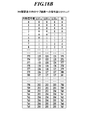
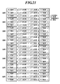
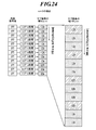
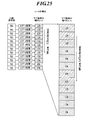
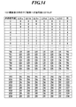
- FIG. 1 is a block diagram showing a schematic configuration of an image display system in the present embodiment. It is explanatory drawing which shows the relationship between a pixel and a sub pixel. It is explanatory drawing which showed typically the process in which original image data was reduced by reduction processing. It is explanatory drawing which showed typically the process in which original image data was reduced by reduction processing. It is explanatory drawing which shows typically the data for a display obtained by the reduction method. It is explanatory drawing explaining the conventional reduction method. It is a table
- 13B is a table showing a modification of the signal distribution LUT in FIG. 13A.
- 13B is a table showing a modification of the monochrome gradation conversion LUT in FIG. 13A.
- 13B is a table showing a modification of the signal distribution LUT in FIG. 13A.
- 13B is a table showing a modification of the monochrome gradation conversion LUT in FIG. 13A.
- 13B is a table showing a modification of the signal distribution LUT in FIG. 13A.
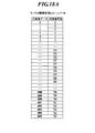
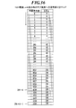
- surface which shows an example of the signal distribution LUT applied when n 6.
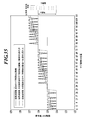
- FIG. 35 is a graph showing an example of signal values after signal conversion processing of a low-frequency image when signal conversion processing is performed with the LUT of FIG. 34.
- FIG. It is a table
- surface which shows the modification of the signal distribution LUT applied when n 6. It is a table
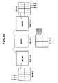
- surface which shows an example of signal distribution LUT in case original image data is color image data. It is explanatory drawing explaining the difference in the arrangement of the sub pixel by the direction of a liquid crystal panel.
- FIG. 1 is a principal block diagram showing a configuration example of an image display system in the present embodiment.
- the image display system 100 is connected to the image generation apparatus 1 via a communication network (not shown) such as a LAN (Local Area Network) or a WAN (Wide Area Network), and is generated by the image generation apparatus 1.
- the captured image data (hereinafter referred to as “original image data”) is received.
- the image generation apparatus 1 includes, for example, an endoscopic image apparatus, an ultrasonic image apparatus, an MRI (Magnetic Resonance Imaging) apparatus, a CR (Computed Radiography) apparatus, a CT (Computed Tomography), a MRT (Magnetic Resonance Imaging), and a breast image generation.
- An apparatus (mammography), an X-ray image apparatus such as an FPD (Flat Panel Detector), or the like. Note that the type and the like of the image generation device 1 are not limited to those exemplified here.
- DICOM Digital Image and Communication Communications in Medicine
- DICOM MWM Mode Worklist Management
- DICOM MPPS Mode Performed Procedure Step
- the image display system 100 includes an image processing unit 3 that performs display data generation processing for generating display data based on original image data generated by the image generation device 1, and display data generated by the image processing unit 3.
- the image display means 5 for displaying an image based on the above, the input unit 7 as an input means for inputting various information, instructions, and the like are provided.
- the image display means 5 is, for example, a monitor that displays medical diagnostic images. As shown in FIG. 1, the image display means 5 drives a liquid crystal panel (LCD (Liquid Crystal Display)) 51 as a monochrome liquid crystal display means for displaying a monochrome image based on display data, and the liquid crystal panel 51.
- LCD Liquid Crystal Display
- a liquid crystal driving unit 52 is provided.
- FIG. 2 is an explanatory diagram schematically showing the pixels constituting the liquid crystal panel 51.
- four pixels A, B, C, and D are extracted and shown.
- each pixel A, B, C, D (portion surrounded by a thick line in FIG. 2) of the liquid crystal panel 51 is in a fixed direction (subpixel arrangement direction: FIG. 2).
- the subpixels a, b, and c (portions surrounded by an alternate long and short dash line in FIG. 2) are arranged.
- the number k of sub-pixels included in one pixel is not limited to three, and k may be an integer of 2 or more.
- the liquid crystal driving unit 52 is a display driving unit that drives the liquid crystal panel 51 for each sub-pixel a, b, c with the sub-pixels a, b, c as one unit based on display data. That is, the display unit control unit 32 of the image processing unit 3 supplies the liquid crystal driving unit 52 with display data (that is, each subpixel a, b, c) of the subpixels a, b, c of the liquid crystal panel 51 as one unit. The output signal value corresponding to c) is sent, and the liquid crystal driving unit 52 uses the display panel to set the liquid crystal panel 51 using each subpixel a, b, c as one unit of gradation expression. Drive.
- the liquid crystal panel 51 can express 8-bit gradation (256 gradations) as gradation characteristics, and the maximum that each sub-pixel a, b, c can represent.
- the number of gradations is 8 bits (256 gradations).
- display data with each sub pixel a, b, c as one unit is sent to the liquid crystal driving unit 52, and each sub pixel a, b, c corresponds to each.
- the output signal value to be assigned is assigned, and the liquid crystal driving unit 52 drives each of the sub-pixels a, b, and c independently.
- the liquid crystal panel 51 is set with one pixel of the liquid crystal panel 51 as one unit of gradation expression. Compared to the case of driving, it is possible to realize three times the resolution. Conventionally, there is a method of independently driving subpixels.
- gradation expression can be performed with the number of gradations that can be expressed by the subpixel (in this embodiment, 8 bits (256 gradations)).
- the sub-pixel in this embodiment, 8 bits (256 gradations)
- the type of the liquid crystal panel 51 applicable to the present embodiment is not particularly limited, and the TN (Twisted ⁇ Nematic) method, STN (Super Twisted Nematic) method, MVA is also used for the method in which the liquid crystal driving unit 52 drives the liquid crystal panel 51.
- TN Transmission ⁇ Nematic
- STN Super Twisted Nematic
- MVA Magnetic Angel Deformation
- Various drive systems such as a (Multi-domain / Vertical / Alignment) system and an IPS (In-Plane / Switching) system can be applied.
- the image display means 5 includes a backlight 53 that irradiates light to the liquid crystal panel 51 from the non-observation side.
- the backlight 53 may be anything as long as it can provide light sufficient to illuminate the liquid crystal panel 51.
- an LED, a cold cathode fluorescent tube, a hot cathode fluorescent tube, and other light emitting elements can be applied.
- the maximum brightness on the observation side is preferably 300 to 5000 cd / m 2 so that it can be suitably used for a monitor for medical purposes.
- the input unit 7 includes a keyboard having character input keys, numeric input keys, and various function keys (not shown), a pointing device such as a mouse, and the like. Is output to the main body control unit 31 as an input signal.
- the input unit 7 inputs information on the image type by a user such as a doctor, displays the display magnification of the image displayed on the liquid crystal panel 51 of the image display unit 5, enlargement display / trimming, and the like. It functions as an input means for inputting selection / designation of a target location when performing.
- a pressure-sensitive (resistive film pressure) touch panel (not shown) in which transparent electrodes are arranged in a grid is formed on the screen of the liquid crystal panel 51 of the image display means 5, and the liquid crystal panel 51, the input unit 7, May be made to function as a means for inputting selection / designation of a target portion when performing enlarged display / trimming.
- the touch panel is configured to detect the XY coordinates of the power point pressed by a finger, a touch pen, or the like as a voltage value and output the detected position signal to the main body control unit 31 as an operation signal.
- the image processing means 3 inputs an input signal value corresponding to monochrome image data having a number of gradations exceeding the maximum number of display gradations that can be expressed independently by a subpixel, corresponding to each subpixel.
- the computer includes a control unit 32, a storage unit 33, and the like.
- the storage unit 33 includes a program storage unit 34, an image processing information storage unit 35, a RAM (Random Access Memory) 36, and the like.
- the program storage unit 34 is a memory that stores information in a readable manner.
- the program storage unit 34 generates display data based on the original image data, or according to the display magnification when the image is displayed on the image display means 5, the image type of the original image data, or the like.
- Various programs such as an image display program for appropriately displaying an image on the image display means 5 such as switching the display method are stored.
- the image processing information storage unit 35 stores various LUTs and data for converting the signal of the original image data and generating display data based on the original image data.
- the RAM 36 is a volatile memory for storing various information, and has a storage area for temporarily storing various information and a work area for developing various programs, data, and the like (none of which are shown).
- the main body control unit 31 acquires the original image data from the image generation apparatus 1
- the original image data is temporarily stored in the storage area of the RAM 36.
- the means for storing the original image data is not limited to the RAM 36, and the image processing means 3 may be provided with a storage unit for storing the original image data.
- the main body control unit 31 includes a CPU (Central Processing Unit) (not shown) and the like, and includes an image type determination unit 37, a display data generation unit 38, and the like.
- the main body control unit 31 develops a program designated from the system program and various application programs stored in the program storage unit 34 in the work area of the RAM 36, and in cooperation with the program expanded in the RAM 36, Execute the process.
- CPU Central Processing Unit
- the main body control unit 31 develops a program designated from the system program and various application programs stored in the program storage unit 34 in the work area of the RAM 36, and in cooperation with the program expanded in the RAM 36, Execute the process.
- the image type determination unit 37 is a functional unit that determines an image type for original image data input via an interface (not shown).
- the image type determined by the image type determination unit 37 includes the number of pixels in the vertical and horizontal directions of the original image data (original image data), whether the original image data is color image data or monochrome image data. Size), the type of the image generation apparatus 1 that generated the original image data, and the like.
- the determination result by the image type determination unit 37 is sent to the display data generation unit 38.
- each original image data as supplementary information (header information of the image data), the type of the image generation apparatus 1 that acquired the original image data, the color information of the image, the number of bits per pixel of the image, the byte per pixel Various information such as the number, the number of pixels in the vertical direction of the image, and the number of pixels in the horizontal direction of the image are attached.
- Each supplementary information is assigned an address and is attached to the original image data in a referenceable form.
- the image type determination unit 37 determines the image type of each image based on the supplementary information attached to the original image data. It comes to judge.
- the conditions considered as the image type are not limited to those exemplified here. For example, the image type may be combined with the number of gradations.
- the determination of the image type by the image type determination unit 37 is not limited to the case where the determination is made based on the incidental information of the original image data.
- information is separately input by the input unit 7 or the like, and based on the input information. You may make it determine.
- the original image data is stored in accordance with the DICOM standard, which is a standard related to the distribution of medical images, the storage format of medical images, and the like.
- the original image data is stored in the header area of the medical image.
- this DICOM standard it is possible to exchange original image data between different apparatuses.
- the method for attaching the auxiliary information to the original image data is not particularly limited.
- the image generation apparatus 1 When the original image data is not stored in the storage format of the DICOM standard, the image generation apparatus 1 is provided with an input unit (not shown). In addition, it is possible to use a method of inputting necessary information from the input unit to obtain auxiliary information, or a method of adding necessary auxiliary information by reading a barcode or the like.
- the display data generation unit 38 includes the number of pixels in the vertical direction and the number of pixels in the horizontal direction of the image of the original image data determined by the image type determination unit 37, and the number of pixels in the vertical direction and the pixels in the horizontal direction of the liquid crystal panel 51.
- the signal conversion process for converting the image signal of each original image data is performed according to the number, the number of gradations of the original image data, the number of gradations that can be displayed on the liquid crystal panel 51, and the like. It is signal conversion means for generating data.
- the display data is composed of output signal values corresponding to the sub-pixels a, b, and c.
- the display data generation unit 38 appropriately reads and applies the gradation conversion LUT from the image processing information storage unit 35, thereby performing image processing of each original image data under image processing conditions corresponding to the image type of the original image data. To generate display data.
- the original image data has 4800 pixels in the vertical direction and 3600 pixels in the horizontal direction of the image, and the number of pixels in the vertical direction of the liquid crystal panel 51 that displays the original image data.
- 1600 pixels and the number of pixels in the horizontal direction are 1200 pixels
- the entire pixels are reduced by reducing the vertical pixels and the horizontal pixels.
- an image is displayed on the liquid crystal panel 51 at a reduction ratio in which the ratio of the number of pixels of display data to the number of pixels of the original image data is 1: 3. It is necessary to generate display data for displaying.
- the number of pixels in the vertical direction of the image is 15 pixels
- the number of pixels in the horizontal direction is 12 pixels
- the number of pixels in the vertical direction of the liquid crystal panel 51 on which the original image data is displayed is 5 pixels.
- the reduction processing is performed with 9 pixels (3 vertical pixels ⁇ 3 horizontal pixels) in the original image data as one pixel, so that the vertical pixel count is 5 pixels and the horizontal pixel count.
- the display data with 4 pixels can be generated.
- pixel values of nine constituent pixels are obtained by performing resampling processing for generating reduced image data by changing the pixel pitch of the pixels in the original image data (hereinafter referred to as “constituent pixels”). Is set to a pixel value of one pixel, which is one unit when an image is displayed on the liquid crystal panel 51.
- a representative value of nine constituent pixels (vertical 3 pixels ⁇ horizontal 3 pixels) is obtained, and reduction is performed with a pixel having the representative value as a pixel value as one pixel.
- This representative value may be one pixel value among the nine constituent pixels, or an average value, median value, and maximum value of the nine constituent pixels may be obtained.
- FIG. 5 schematically shows a decrease in the number of pixels when display data is generated by this method.
- the above is a conventional method. According to this method, even when the number of pixels of the original image data is large and the entire image cannot be displayed on the liquid crystal panel 51 as it is, the entire image is displayed on the liquid crystal panel 51. Display data can be generated.
- the number of pixels in the arrangement direction (vertical direction in FIG. 6) of the sub-pixels a, b, c is the same as the number of constituent pixels, and the sub-pixel a , B, c to generate display data by obtaining new pixel values so that the number of pixels in the direction orthogonal to the arrangement direction (horizontal direction in FIG. 6) is one third of the number of constituent pixels. .
- the number of gradations of the input signal value is converted in accordance with the number of gradations of the liquid crystal panel 51, and a signal conversion process for converting the input signal value into the output signal value is performed.
- the maximum display gradation number of the liquid crystal panel 51 is 256 gradations. It is. Therefore, monochrome gradation conversion processing is performed for converting the number of gradations of the original image data of 4096 gradations to 256 gradations (FIG. 6C), and outputs corresponding to the sub-pixels a, b, and c. Get the signal value.
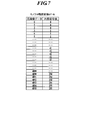
- FIG. 7 shows an example of a monochrome gradation conversion LUT (“LUT-N” in FIG. 7) applied in this monochrome gradation conversion process.
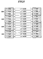
- FIG. 8 schematically shows signal conversion processing for obtaining the output signal values of the sub-pixels a, b, and c by performing signal conversion processing using the LUT-N for the sub-pixels a, b, and c. Is.
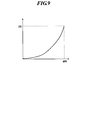
- the LUT-N for performing the monochrome gradation conversion process may be a simple proportional relationship, or may be a curved LUT with display gradation characteristics as shown in FIG.
- the LUT-N sets input signal values from 0 to 4095 (that is, 4096-1) from 0 to all output signal values so that the maximum number of gradations is 256.
- the signal is converted to 255 (that is, 256-1).
- 256-gradation display image data with each sub-pixel a, b, c as one unit of gradation representation is generated (FIG. 6D).
- the number of pixels in the vertical direction that is, the subpixel arrangement direction
- the horizontal direction that is, the direction orthogonal to the subpixel arrangement direction).
- FIG. 11 schematically shows a decrease in the number of pixels when display data is generated by this method.
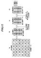
- the reduction methods employed in the present embodiment are first configured in three ways only in the horizontal direction in the original image data (FIG. 12A), as described with reference to FIG.
- a representative value of the pixel is obtained and resampling is performed to obtain an input signal value that is reduced image data of the original image data (FIG. 12B).
- a predetermined LUT is applied to the original image data after the reduction process, and the first signal conversion process is performed so as to obtain a desired display gradation number when the entire image is displayed on the liquid crystal panel 51 (FIG. 12 (c)).
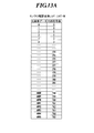
- FIG. 13A shows a monochrome image for converting the original image data into an internal signal value of the maximum number of display gradations when displaying the entire image on the liquid crystal panel 51 when the original image data is a 4096 gradation monochrome signal.
- An example of a monochrome gradation conversion LUT (“LUT-M” in FIG. 13A) applied when gradation conversion processing is performed as the first signal conversion processing is shown.
- the LUT-M for performing the monochrome gradation conversion processing may be a simple proportional relationship, or may be a curved LUT in consideration of display gradation characteristics as shown in FIG.
- the maximum number of gradations 1 that can be expressed by each of the sub-pixels a, b, and c is 256 gradations.
- the three sub-pixels a, b, and c are used as one unit for multi-gradation display, and each sub-pixel a, A case where the entire image is displayed on the liquid crystal panel 51 by combining the three sub-pixels a, b, and c to express multiple gradations while driving b and c independently will be described.
- the maximum display gradation number of the liquid crystal panel 51 is 766 gradations (255 ⁇ 3 + 1). Therefore, the LUT-M shown in FIG. 13A has a liquid crystal panel so that the maximum number of gradations that can represent an input signal value from 0 to 4095 (ie, 4096-1) in each pixel is 766 gradations.
- the internal signal value is obtained by performing signal conversion so that all output signal values for each pixel in 51 are from 0 to 765 (ie, 766-1).
- the internal signal value is converted into the number of gradations according to the maximum number of gradations that can be expressed by the sub-pixels a, b, and c of the liquid crystal panel 51, and a signal distribution process for distributing the internal signal values to the sub-pixels a, b, and c.
- the second signal conversion process is performed.
- the maximum number of gradations obtained by applying the LUT-M is subtracted from the internal signal value of 766 gradations.
- Three types of signal distribution LUTs corresponding to the pixels a, b, and c are applied to convert the internal signal values into output signal values corresponding to the sub-pixels a, b, and c. Thereby, multi-gradation display can be performed.
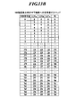
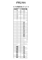
- FIG. 13B shows an example of a signal distribution LUT (LUT-a, LUT-b, LUT-c) used for the second signal conversion process
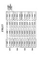
- FIG. 15 shows the subpixels a, b
- LUT-a, LUT-b, and LUT-c all have internal signal values from 0 to 765 (ie, 766-1), the maximum number of gradations is 256, The signal is converted so that the output signal value becomes 0 to 255 (that is, 256-1).
- the display data generation unit 38 which is a signal conversion means, applies such an LUT to perform signal conversion processing, whereby each subpixel a, b, c is represented as one unit of gradation expression. 256-gradation display image data is generated (FIG. 12D).
- the display data generation unit 38 serving as signal conversion means outputs an output signal value corresponding to the same input signal value.
- signal conversion processing can be performed on the signals corresponding to the three sub-pixels a, b, and c without overlapping, and the three sub-pixels a , B and c, three output signal values are obtained.
- the output signal value converted by the display data generation unit 38 ranges from 0 to l ⁇ 1, where l is the maximum number of display gradations that each subpixel a, b, and c can represent independently.
- the number of sub-pixels obtained corresponding to the same input signal value (the number of sub-pixels serving as one unit of signal conversion processing. For example, when three sub-pixels are used as one unit of signal conversion processing)
- the sum A of the output signal values is preferably configured so that all integers from 0 to n ⁇ (l ⁇ 1) exist, but the present invention is not limited to this.
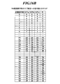
- some numerical values of the sum A of the output signal values may overlap. That is, in FIG. 16B, the part surrounded by the dotted line partially overlaps numerical values such as “3, 3” and “377, 377”, but such overlap may exist.
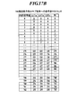
- FIGS. 16A and 16B when the internal signal value is larger than 766 gradations which is the maximum display gradation number of the liquid crystal panel 51, a partial value of the sum A of the output signal values is set. Respond by overlapping. Further, as shown in FIG.
- the LUT-a, LUT-b, and LUT-c may perform signal conversion processing in which the value A of the output signal values has such a relationship.
- the maximum number of gradations 1 that can be expressed by each of the sub-pixels a, b, and c is 256 gradations, and two sets of the sub-pixels a, b, and c (that is, 6 for two pixels in the liquid crystal panel 51).
- the liquid crystal panel 51 A case where the entire image is displayed will be described.
- the maximum display gradation number of the liquid crystal panel 51 is 1531 gradations (255 ⁇ 6 + 1). Therefore, the monochrome gradation conversion LUT (LUT-M) shown in FIG. 19 has an input signal value from 0 to 4095 (that is, 4096-1), and the maximum number of gradations that can be expressed in each pixel is 1531 floors. The signal conversion is performed so that all output signal values for each pixel in the liquid crystal panel 51 become 0 to 1530 (that is, 1531-1) so that the internal signal value is obtained.
- the internal signal value is converted into the number of gradations according to the maximum number of gradations that can be expressed by the sub-pixels a, b, and c of the liquid crystal panel 51, and a signal distribution process for distributing the internal signal values to the sub-pixels a, b, c
- the second signal conversion process is performed.
- the maximum number of gradations obtained by applying LUT-M is 6 for the internal signal value of 1531 gradations.
- Six types of LUTs corresponding to the two sub-pixels a, b, and c are applied to convert the internal signal values into output signal values corresponding to the sub-pixels a, b, and c. Thereby, multi-gradation display can be performed.
- FIG. 20 shows examples of LUT-a, LUT-b, LUT-c, LUT-d, LUT-e, and LUT-f used for the second signal conversion processing.
- Signal conversion processing is performed by applying LUT-a, LUT-b, LUT-c, LUT-d, LUT-e, and LUT-f to each of the six sub-pixels a, b, and c, and the sub-pixels a, b , C schematically represents signal conversion processing for obtaining output signal values corresponding to c.
- LUT-a, LUT-b, LUT-c, LUT-d, LUT-e, and LUT-f all have internal signal values from 0 to 1530 (ie, 1531-1).
- the signal conversion is performed so that all output signal values are 0 to 255 (that is, 256-1) so that the maximum number of gradations is 256 gradations.
- the display data generation unit 38 which is a signal conversion unit, applies such an LUT to perform signal conversion processing, whereby six sub-pixels a, b, and c are represented by 1 in gradation expression. Display image data of 256 gradations as a unit is generated.
- the display data generation unit 38 serving as a signal conversion unit generates one input signal value.
- the display data generation unit 38 serving as a signal conversion unit generates one input signal value.
- the display data generation unit 38 determines the value of the number n of subpixels as one unit of signal conversion processing according to the image type of the original image data, the display characteristics of the liquid crystal panel 51, and the like. It has become.
- the display data generation unit 38 determines the value of n according to the type of the image generation device 1 that generated the original image data. For example, an image acquired by a CR device or a simple X-ray image acquired by an FPD device or the like has a large number of gradations of the original image data, so that the value of n is increased and displayed in multiple gradations. Is preferred. For this reason, when the image generation apparatus 1 that generated the original image data is an X-ray imaging apparatus such as a CR apparatus or an FPD, the balance between the luminance resolution of the human eye and the calculation processing time in the display data generation unit 38 is balanced.
- the display data generation unit 38 determines the type of the image generation apparatus 1 based on the incidental information of the original image data, and the image generation apparatus 1 that generated the original image data is a CR apparatus or an X-ray imaging apparatus.
- the value of n is determined to be 3 to 6, and the number of LUTs corresponding to the determined value of n is selected to perform the signal conversion process.
- an image captured by a CT apparatus, an MRI apparatus, or the like has a small number of gradation levels of the original image data, and in many cases has 256 gradation levels. Therefore, it is not always necessary to display an image captured with a CT apparatus, an MRI apparatus, or the like with the number of gradations higher than that of the original image. There is no need to perform the signal conversion processing as described above.
- the display data generation unit 38 may determine the value of n according to the number of gradations of the original image data.
- the number of gradations of the original image data is derived from the type or the like of the image generation apparatus 1 that generated the original image data, but even if there is no information of the image generation apparatus 1, the number of gradations of the original image data
- information such as the type of the image generation device 1 that generated the original image data and the number of gradations of the original image data is simple and preferable to obtain from the incidental information of the original image data, but is not limited thereto.
- information for determining n from the input unit 7 may be input, and the display data generation unit 38 may determine the value of n based on the information input from the input unit 7.
- the display data generation unit 38 determines the value of n according to the maximum luminance (cd / m 2 ) of the liquid crystal panel 51.
- the maximum luminance of the liquid crystal panel 51 is high, the ability to discriminate the luminance difference per gradation of human eyes increases. Therefore, the higher the maximum luminance of the liquid crystal panel 51, the larger the number of gradations of display data. Is preferred. Therefore, for example, the image processing information storage unit 35 or the like stores n association information that associates the maximum luminance of the liquid crystal panel 51 with the value of n as shown in FIG. By referring to the n association information, the value of n corresponding to the maximum luminance is determined so that the higher the maximum luminance of the liquid crystal panel 51 is, the larger n is.
- the display data generation unit 38 determines the value of n according to the pixel size of the liquid crystal panel 51.
- the pixel size of the liquid crystal panel 51 is large, if the value of n is increased, the period of the portion that is different by one gradation becomes longer due to different signal processing in the portion where the same signal value continues in the original image data ( That is, the frequency becomes low) and it is easy to be visually recognized as noise.
- the image processing information storage unit 35 or the like stores an LUT that associates the pixel size of the liquid crystal panel 51 (“monitor” in FIG. 23) with the value of n as shown in FIG.
- the generation unit 38 refers to the LUT, and determines the value of n according to the pixel size so that the smaller the pixel size of the liquid crystal panel 51, the smaller n.
- a method for the display data generation unit 38 to acquire information on the maximum luminance of the liquid crystal panel 51 and information on the pixel size of the liquid crystal panel 51 is not particularly limited, but for example, the liquid crystal panel 51 connected to the image display system 100.
- the display data generator 38 stores the display characteristic information in advance in the storage unit 33 and the like, and the display data generation unit 38 refers to this information as appropriate, thereby information on the maximum luminance of the liquid crystal panel 51 and information on the pixel size of the liquid crystal panel 51. And determine the value of n.
- the value of n may be determined in association with information such as the model number of the image display means and the total number of pixels.
- the number n of sub-pixels which is a unit of signal conversion processing, is the number of sub-pixels constituting each pixel in the liquid crystal panel 51 and an integer multiple thereof from the standpoint of ease of arithmetic processing.
- the number n of subpixels as one unit of signal conversion processing may be an integer equal to or greater than 2.
- n 5 or the like.
- the display data generated by the display data generation unit 38 is sent to the display means control unit 32.
- the display unit control unit 32 inputs display data sent from the display data generation unit 38 to the liquid crystal driving unit 52 of the image display unit 5, whereby the image display unit 5.
- the image display means 5 is controlled so that the liquid crystal panel 51 displays images, characters, and the like based on the display data.
- the display means control unit 32 inputs display data including output signal values corresponding to the sub-pixels a, b, and c to the liquid crystal driving unit 52, and converts the sub-pixels a, b, and c to gradations.
- the liquid crystal driving unit 52 is controlled to drive the liquid crystal panel 51 as one unit of expression.
- a graphic board or the like can be used as the display means control unit 32.
- the main body control unit 31 determines the image type or the like of the original image data (step S3), and the determination result is sent to the display data generation unit 38.
- the storage unit 33 stores information related to display characteristics such as the maximum luminance and pixel size of the liquid crystal panel 51 of the image display means 5, and the display data generation unit 38 uses the image type determination unit 37. Based on the determination result and the display characteristics of the liquid crystal panel 51, the number n of sub-pixels, which is one unit of signal conversion processing, is determined (step S4).
- the display data generation unit 38 sets the ratio between the subpixel arrangement direction and the direction orthogonal thereto, where k is the number of subpixels a, b, c in the arrangement direction of the subpixels a, b, c. Resampling processing is performed on the original image data so that becomes k: 1 (step S5).
- the display data generation unit 38 applies a monochrome gradation conversion LUT (LUT-M) to the input signal value subjected to the resampling process, and supports the maximum display gradation number of the liquid crystal panel 51.
- a monochrome gradation conversion process (first signal conversion process) for obtaining the internal signal value is performed (step S6).
- n 3, LUT-a, LUT-b, LUT-c
- the generated display data is sent to the display means control section 32, and the display means control section 32 inputs the sent display data to the liquid crystal drive section 52 of the image display means 5 (step S9).
- the liquid crystal driving unit 52 drives each sub-pixel of the liquid crystal panel 51 based on the display data input from the display means control unit 32, so that the entire image corresponding to the original image data fits in the liquid crystal panel 51. It is displayed (step S10).
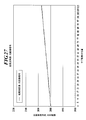
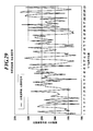
- FIGS. 27 and 29 are obtained by taking a profile in the sub-pixel direction for the image signal of the original image before image processing.
- FIG. 27 is an example of a low-frequency image, that is, an image of a portion where the density changes smoothly little by little, such as an abdominal X-ray image.
- FIG. 29 is an example of a high-frequency image, that is, an image of a portion where the density change is intense and changes very finely.
- fine components such as various organs such as blood vessels, bones, and lungs.
- These include X-ray images of the chest that contain a lot of breasts, and X-ray images of breasts that contain many fine components such as microcalcifications and mammary glands.
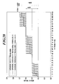
- FIG. 28 shows the processing result when the conventional sub-pixel independent drive signal conversion processing is performed on the low-frequency image shown in FIG. 27, and one unit of the signal conversion processing among the methods shown in this embodiment.
- the processing result when the number n of sub-pixels is 3 is shown.
- the signal value changes only in three stages of 124, 125, and 126 between the sub-pixels 1 to 113.
- the signal value changes for each sub-pixel. Therefore, if this is viewed microscopically, the signal value that has a very fine amplitude as shown by a straight line is obtained. Obtainable.
- the output signal values of these three subpixels as shown by the one-dot chain line. Is taken as an intermediate brightness with a moving average of. Since the amplitude of the signal is as small as one gradation of 256 gradations and the period is also small at the 100 ⁇ level, the amplitude of this signal cannot be grasped microscopically by the human eye, It is captured with a macroscopic appearance as shown by the alternate long and short dash line. For this reason, in the present embodiment, it is possible to display a portion that can only express three gradations by the conventional method so that it can be seen as nine gradations in a pseudo manner.
- FIG. 30 shows a processing result when the conventional subpixel independent drive signal conversion processing is performed on the high-frequency image shown in FIG. 29 and one unit of the signal conversion processing among the methods shown in this embodiment.
- the processing result in the case where the number n of sub-pixels is 3 is shown.
- the high-frequency image has a part in which the pixel value is slightly different from the conventional sub-pixel independent driving method.
- information with a high frequency and a small signal difference cannot be visually recognized by human eyes, even if there is a slight difference in the signal value, there is almost no difference in the actual appearance, which may hinder diagnosis. It is not a thing.
- the low frequency component of the image information is visually recognized at a high gradation by a combination of n subpixels, and the high frequency component of the image information is visually recognized at a high resolution in units of subpixels.
- a gradation image can be diagnosed.
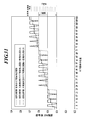
- FIG. 31 shows the processing result when the conventional sub-pixel independent drive signal conversion processing is performed on the low-frequency image shown in FIG. 27 and the signal conversion processing of the method shown in this embodiment.
- the signal value changes only in three stages of 124, 125, and 126 between the sub-pixels 1 to 113 as described above.
- the signal value changes for each sub-pixel. Therefore, if this is viewed microscopically, the signal value that has a very fine amplitude as shown by a straight line is obtained. Obtainable.
- this subpixel It is perceived as an intermediate brightness obtained by taking a moving average of the output signal values. Since the amplitude of the signal is as small as one gradation of 256 gradations and the period is also small at the 100 ⁇ level, the amplitude of this signal cannot be grasped microscopically by the human eye, It is captured with a macroscopic appearance as shown by the alternate long and short dash line. For this reason, in the present embodiment, it is possible to display a portion that can only be expressed with 3 gradations by the conventional method so that it can be seen as 18 gradations in a pseudo manner.
- FIG. 32 shows the processing result when the conventional subpixel independent drive signal conversion processing is performed on the high-frequency image shown in FIG. 29, and one unit of the signal conversion processing among the methods shown in this embodiment.
- the processing result in the case where the number n of sub-pixels is 6 is shown.
- the high-frequency image has a part in which the pixel value is slightly different from the conventional sub-pixel independent driving method.
- information with a high frequency and a small signal difference cannot be visually recognized by human eyes, even if there is a slight difference in the signal value, there is almost no difference in the actual appearance, which may hinder diagnosis. It is not a thing.
- the low frequency component of the image information is visually recognized at a high gradation by a combination of n subpixels, and the high frequency component of the image information is visually recognized at a high resolution in units of subpixels.
- a gradation image can be diagnosed.
- the sub-pixels a, b, and c are expressed in gradation. Therefore, the resolution can be increased. Further, in the signal conversion process, by applying different LUTs to the sub-pixels a, b, and c periodically, the shift is made so that the output signal values corresponding to the sub-pixels a, b, and c are slightly different. Can be generated. Thereby, when the image is observed macroscopically, a multi-gradation image exceeding the maximum number of gradations that can be expressed by each of the sub-pixels a, b, and c can be displayed.
- the sub-pixel is one unit of gradation expression microscopically, and the combination of n pixels is one unit of gradation expression macroscopically.
- a multi-tone image can be displayed on the liquid crystal panel 51.
- the display data generation unit 38 determines the number of sub-pixels as one unit of signal processing according to the type of the image generation device 1, the number of gradations of the original image data, the maximum luminance of the liquid crystal panel 51, the pixel size, and the like. Since n is determined, signal conversion processing most suitable for the image data and the liquid crystal panel 51 can be performed.
- the signal distribution process when the number n of sub-pixels that is one unit of the signal conversion process is 3, for the sub-pixels a, b, and c Three LUTs (LUT-a, LUT-b, LUT-c) are periodically applied in order, and when n is 6, for sub-pixels a, b, c, a, b, c, An example in which six LUTs (LUT-a, LUT-b, LUT-c, LUT-d, LUT-e, and LUT-f) are periodically applied in this order is shown as an example.
- n LUTs When the n LUTs are periodically applied in order, it is preferable because a multi-gradation can be expressed by a combination of arbitrary consecutive n sub-pixels.
- the subpixels may be a combination of subpixels a, b, and c, or a combination of subpixels b, c, and a lower by one subpixel in the subpixel arrangement direction of FIG. 766 gradations can also be expressed by a combination of the sub-pixels c, a, and b below by two.
- the method of applying the LUT is not limited to this. It is only necessary that the LUTs applied to the n sub-pixels do not overlap. For example, as shown in FIG.
- the sub-pixels a, b, c, a, b, c have 1
- LUTs are applied in the order of “LUT-a, LUT-b, LUT-c, LUT-d, LUT-e, LUT-f”, and in the second period, “LUT-a, LUT-d,
- the six LUTs may be applied randomly without overlapping, such that the LUTs are applied in the order of “LUT-c, LUT-f, LUT-e, LUT-b”.
- n is large, such as when the number n of subpixels that are one unit of signal conversion processing is 6, a low-frequency image is displayed when the same output signal value is distributed to adjacent subpixels.
- the amplitude of the signal is reduced, and the frequency of the noise component is lowered, so that it is easily detected by human eyes.
- different signals are arranged alternately.
- the number of LUTs corresponding to the number n of sub-pixels which are one unit of signal conversion processing is prepared as the signal distribution LUT and is switched in order and applied periodically.
- the number of LUTs to be prepared need not be n.
- the number n of sub-pixels as one unit of signal conversion processing is 6, instead of providing six LUTs, one LUT as shown in FIG. 36 is prepared, and the signal conversion processing is performed.
- the output signal value corresponding to each sub-pixel is calculated while sequentially adding 6 extra offsets to the internal signal value corresponding to each sub-pixel. Thereby, it is possible to obtain the same effect as when applied while switching six LUTs.
- the signal conversion process is not limited to the one using the LUT, and may be performed using, for example, a calculation formula.
- the monochrome gradation conversion LUT-M used for the monochrome gradation conversion process (first signal conversion process), the signal distribution LUT-a used for the signal distribution process (second signal conversion process), LUT-b, LUT-c,... are separately provided and sequentially applied to perform signal conversion processing in two stages, but the method of LUT and signal conversion processing is not limited to this.
- a combined LUT (LUT-Ma, LUT-Mb, LUT-Mc...) Of monochrome gradation conversion LUT-M and signal distribution LUT-a, LUT-b, LUT-c.
- the signal conversion process may be performed in one step by applying the synthesis LUT.
- the ratio between the number of pixels of the display data and the number of pixels of the original image data is one pair.
- the reduction rate is 3
- the reduction rate is not limited to this.
- the display data may be an enlargement of the original image data.
- the method for obtaining new pixel data when the image is reduced is not limited to this embodiment.
- various commonly used interpolation methods such as closest interpolation, linear interpolation, spline interpolation, bicubic interpolation, and simple average / weighted average of a plurality of pixels can be used.
- a filtering process that attenuates the high-frequency noise component may be performed during the interpolation.
- Different interpolation methods may be used depending on the reduction ratio, or different interpolation methods may be used for the subpixel arrangement direction and the direction orthogonal thereto.
- linear interpolation is performed in both the subpixel arrangement direction and the direction orthogonal thereto, and frequency enhancement processing is performed in the subpixel arrangement direction. May be subjected to frequency attenuation processing in a direction orthogonal to the subpixel arrangement direction.
- bicubic interpolation may be used as an interpolation method. By performing such interpolation, it is preferable that noise generated when the image is reduced can be further reduced.
- the interpolation process and the frequency process may be performed in two stages, but the process can be completed in one stage by performing an interpolation using a weighting coefficient having a frequency processing effect. Thus, it is preferable to perform the process in one stage because the calculation time can be shortened.
- the image generation apparatus 1 is connected to the image display system 100 via a communication network.
- external devices connected to the image display system 100 are not limited to the image generation apparatus 1.
- a patient information storage device that stores electronic medical record information or the like may be connected to the image display system 100.
- the image generation apparatus 1 is connected to the image display system 100.
- a PACS Picture Archiving and Communication System
- a PACS server to be managed may be connected to the image display system 100 via a communication network.
- the image display system 100 is configured to acquire the original image data by reading the original image data and the like collectively managed in the PACS server.
- the PACS server stores patient information such as original image data and electronic medical record information generated by various image generating apparatuses in a database.
- the original image data and the like are stored in accordance with the DICOM standard, and various information relating to the image data is written in the header area of the image data and added to the database as incidental information. Even when the PACS server is not connected to the communication network, it is only necessary that the storage means for storing the original image data generated by the individual image generation apparatuses is connected to the image display system 100 via the communication network.
- the image display processing program is stored in the program storage unit 34 of the image processing means 3, but the storage destination of the image display processing program is not limited to the one illustrated here.
- the main body control unit 31 may read a program stored in an external storage unit and expand it in the RAM 36.
- the liquid crystal panel 51 is provided as the image display unit.
- the image display unit is not limited to the liquid crystal panel as long as it can display a medical image with high luminance.
- a CRT (Cathode Ray Tube) display or the like may be used as the image display means.
- the case where the original image data is monochrome image data has been mainly described.
- the original image data is color image data
- Resampling is performed so that the ratio between the pixel arrangement direction and the direction perpendicular thereto is 1: 1, and then signal conversion processing is performed with the pixel as one unit of gradation expression, and color image data is converted. Display with the brightness associated with the brightness displayed on the color monitor. That is, in this case, for example, as shown in FIGS. 37A and 37B, the signal value of each RGB component of the color image data is the ratio of the visibility of the human eye to each RGB component (or representative color).
- the result is converted to monochrome image data of 4095 gradations by rounding off the result, for example, by 4095/255.
- a signal distribution process for distributing values to the three sub-pixels is performed on the monochrome image data by applying a signal distribution LUT as shown in FIG.
- a color image can be displayed with a luminance ratio substantially equal to that displayed on the color liquid crystal monitor.
- the LUT in FIG. 13B switches LUT-a for sub-pixel a, LUT-b for sub-pixel b, and LUT-c for sub-pixel c with respect to the internal signal value corresponding to each sub-pixel.
- the method of converting the signal values of the RGB components into signal values for driving the sub-pixels of the monochrome display means when displaying a color image is not limited to the above.
- the signal values of the RGB components are respectively 0.30, 0.59, 0.
- a value obtained by multiplying the weighting coefficient of 11 may be used as the output signal value of the sub-pixels a, b, and c included in the pixel.
- the weighting coefficients may be set to 0.51, 1.0, and 0.19.
- the coefficients are larger than when 0.30, 0.59, and 0.11 are used as the weighting coefficients, it is possible to increase the display brightness of the image. Furthermore, it is possible to minimize the demerit that the number of gradations is reduced by multiplying by a weighting coefficient smaller than 1.
- R, G, B color image signals defined by an operating system (hereinafter referred to as “OS”).
- OS operating system
- the liquid crystal drive unit drives the sub-pixels a, b, and c in response to the R, G, and B color image signals.
- the image processing means performs image processing based on the arrangement method of the sub-pixels a, b, and c and the correspondence relationship between the sub-pixels a, b, and c and the signal values of R, G, and B.
- the sub-pixels a, b, and c are in the vertical direction of the image.
- the reduction processing is performed so that the unit becomes one unit of gradation expression, and the pixel becomes one unit of gradation expression in the left-right direction of the image.
- the sub-pixels a, b, and c are arranged in the left-right direction (see “horizontal orientation” on the left and right sides in FIGS. 39 and 40)
- the sub-pixels a, b, c The reduction processing is performed so that c is one unit of gradation expression and the pixel is one unit of gradation expression in the vertical direction of the image.
- the signal values are distributed in consideration of which of the R, G, and B signal values the sub-pixels a, b, and c are driven to correspond to. For example, when the sub-pixels a, b, and c correspond to the order of R, G, and B, and when the sub-pixels a, b, and c correspond to the order of B, G, and R, the signal distribution order Is different.
- the order of signal distribution varies. That is, when the subpixels are arranged in the order of a, b, c, a, b, c..., The signal values are associated in the order of R, G, B, R, G, B. In some cases (Case 1) is associated with signal values in the order of B, G, R, B, G, R... (Case 2), and the sub-pixels are c, b, a, c, b.
- Case 1 and Case 3 Case 2 and Case 4 have the same signal distribution order
- Case 1 and Case 3 have the same signal distribution order as Case 2 and Case 4.
- the distribution of the R, G, and B signals of the image signal with respect to the arrangement order of the sub-pixels is performed so that the order of the image information in the vertical direction and the horizontal direction is maintained in the order to be displayed.
- the arrangement order of the subpixels in the left-right direction that is, the arrangement order of the R, G, and B signals of the image signal
- the arrangement order of the subpixels in the left-right direction that is, the arrangement order of the R, G, and B signals of the image signal
- the arrangement order of the sub-pixels is c, b, a, c from the left.
- B, a... Are associated with signal values in the order of R, G, B, R, G, B... From the left (Case 3).
- FIG. 1 In FIG.
- the arrangement order of the sub-pixels is R, G, B, R, from the top with respect to c, b, a, c, b, a.
- the arrangement order of the sub-pixels is a, b, c.
- the order of sub-pixels and the R, G, B signals, such as associating signal values in the order of R, G, B, R, G, B.
- Various combinations are possible for the association. The same applies to the case of FIG.
- the structure of subpixels differs depending on the liquid crystal panel. Also, the direction in which the sub-pixels are arranged differs by 90 degrees depending on whether the monitor (liquid crystal panel) is placed vertically or horizontally (see FIGS. 39 and 40).
- information for associating a, b, c with R, G, B signals defined by the OS and information on whether the monitor is placed vertically or horizontally is stored for each monitor, or the OS, device Information is acquired from the driver (display means control unit, liquid crystal drive unit) and the monitor itself, and the vertical and horizontal display magnifications and / or how to assign signals to the sub-pixels a, b, and c are selected according to the information. It is preferable to configure as described above.
- the image processing unit 3 distributes the signal value in consideration of which signal value of R, G, and B is driven corresponding to each of the sub-pixels a, b, and c is shown.
- the image processing means 3 uniformly distributes the signal without considering which of the R, G, and B signal values the sub-pixels a, b, and c are driven to correspond to, and the display driving means.
- the liquid crystal driving unit 52 of a certain image display means 5 the subpixels a, b, c and the R, R, and B of the image signal are maintained so that the order of the image information in the vertical direction and the horizontal direction is maintained. It is preferable to switch the correspondence between the G and B signals because the algorithm of the image processing unit can be simplified.
- a plurality of image display means 5 may be connected to the image display system 100.
- a value of n is determined in advance for each image display means 5, and this is associated with each image display means 5 and stored in the storage unit 33 or the like. It is preferable to memorize.
- the display data generation unit 38 as the signal conversion means selects the LUT used for the signal conversion process based on the stored value n and performs the signal conversion process. As a result, even when each image display means 5 has different maximum brightness, pixel size, etc., it is possible to perform signal conversion processing using an appropriate LUT.
- the example in which the program storage unit 34 and the image processing information storage unit 35 are provided in the image processing unit 3 has been described.
- the program storage unit 34 and the image processing information in the image processing unit 3 are described.
- the storage unit 35 may not be provided, and various programs and LUTs may be collectively managed by a server (not shown) or the like.
- a server not shown
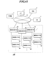
- FIG. 41 when the network N includes a plurality of image processing means 3 (3a, 3b, 3c) and a plurality of image display means 5 (5a to 5f) controlled thereby, any one of the image processing means 3 (in FIG.
- the image processing means 3a) is a server combined machine, and only the image processing means 3a is provided with a program storage unit 34 and an image processing information storage unit 35.
- the image processing information storage unit 35 for example, a monochrome gradation conversion LUT and a signal distribution LUT necessary for the image display processing of the present embodiment, and the image type and the characteristics of the liquid crystal panel 51 and one unit of the signal conversion processing are used.
- n association information Stored is n association information that associates the number n of sub-pixels. In this case, information such as the display characteristics of the image display means 5 controlled by the image processing means 3b and 3c is sent to the image processing means 3a, and the image processing means 3a determines the display characteristics and the like of each image display means 5.
- the corresponding LUT may be stored in association with each image display means 5.
- the other image processing units 3b and 3c access the program storage unit 34 and the image processing information storage unit 35 of the image processing unit 3a as appropriate, read out necessary application programs and LUTs, and perform signal conversion processing.
- a server (not shown) that collectively manages data may be provided separately from the image processing means 3, and the program storage unit 34 and the image processing information storage unit 35 may be provided with this server.
- each image processing means 3 is connected to a server and configured to be able to read out programs and LUTs stored in the program storage unit 34 and the image processing information storage unit 35 of the server.
- Information such as display characteristics of the image display means 5 controlled by the image processing means 3 is sent to the server, and the server corresponds to each image display means 5 with an LUT corresponding to the display characteristics of each image display means 5. You may make it memorize it.
Landscapes
- Engineering & Computer Science (AREA)
- Chemical & Material Sciences (AREA)
- Crystallography & Structural Chemistry (AREA)
- Physics & Mathematics (AREA)
- Computer Hardware Design (AREA)
- General Physics & Mathematics (AREA)
- Theoretical Computer Science (AREA)
- Control Of Indicators Other Than Cathode Ray Tubes (AREA)
- Liquid Crystal (AREA)
- Liquid Crystal Display Device Control (AREA)
- Video Image Reproduction Devices For Color Tv Systems (AREA)
- Controls And Circuits For Display Device (AREA)
Abstract
簡易な手法により、高解像度で、かつ多階調の画像を表示させることのできる画像表示システム及び画像表示プログラムを提供する。 そのため、表示用データ生成部(38)によって変換される出力信号値が、サブ画素a,b,cが単独で表現することのできる最大表示階調数をlとしたとき、0からl-1までのいずれかの整数であり、サブ画素a,b,cの配列方向に連続するサブ画素n個(nは2以上の整数)を信号変換処理の1単位とし、入力信号値に対する出力信号値の関係が異なるn個の信号変換処理を、信号変換処理の1単位を構成するn個のサブ画素に対して重複なく行うことによりn個の出力信号値を得て、サブ画素a,b,cが単独で表現することのできる最大表示階調数を超える階調数のモノクロ画像を表示させるようにする。
Description
本発明は、画像表示システム及び画像表示プログラムに関するものである。
従来、X線診断装置、MRI(Magnetic Resonance Imaging 磁気共鳴映像法)診断装置、各種CT(Computed Tomography コンピュータ断層撮影)装置などの医療用診断装置で撮影された撮影画像(医用画像)は、通常、X線フィルムやその他のフィルム感光材料などの光透過性の画像記録フィルムに記録され、光透過性の画像として再生される。この医用画像が再生されたフィルムは、シャーカステンと呼ばれる観察用の装置にセットされて、背面から光を照射された状態で観察され、病変箇所の有無等の診断が行われる。
また、近年は、各種の医療用診断装置で撮影された医用画像を、CRT(Cathode Ray Tube)ディスプレイやLCD(Liquid Crystal Display 液晶ディスプレイ)等のモニタに出力し、モニタに出力された画像により、診断等が行われている。
しかし、特に医療用診断装置で撮影されるモノクロ画像は、その元画像データの画素数が多く、そのままではモニタに出力した際に、1画面に画像全体を表示させることができない。このため、従来、モニタの1画素を構成する複数のサブ画素を階調表現の1単位とし、元画像データを縮小して画像全体が1画面に収まるように調整して表示させることが行われている(例えば、特許文献1、非特許文献1参照)。
しかし、一般にモニタのサブ画素が表現できる階調数(表示階調数)は、8ビット(256階調)であり、一律にサブ画素を階調表現の1単位としたのでは、256階調を超える多階調の画像表示を行うことができない。
他方で、複数のサブ画素を組み合わせて1画素を表現し、この1画素を階調表現の1単位とした場合には、多階調の画像表示を行うことはできるが、その分元画像データからの縮小率を大きくしなければ、1画面に画像全体を収めることができない。
この点、カラー画像を表示する際には画素を階調表現の1単位とし、モノクロ画像を表示する際にはサブ画素を階調表現の1単位とする技術が提案されている(例えば、特許文献2参照)。これによれば、カラー画像については多階調の表示を行うことが可能となる。
しかし、上記各従来技術では、モノクロ画像を高い解像度で表示しようとすると階調数が8ビット(256階調)となり、モノクロ画像の表示階調を多階調とすると解像度が低くなる。
また、特許文献2の技術は複数色の光源を有するカラー表示装置に関するものであり、光源の点灯・消灯を時分割的に制御するので、構成が複雑になるという欠点を有する。
また、特許文献2の技術は複数色の光源を有するカラー表示装置に関するものであり、光源の点灯・消灯を時分割的に制御するので、構成が複雑になるという欠点を有する。
そこで、解像度は高いが表示階調数が8ビット(256階調)となるモードと、表示階調を多階調とすることができるが解像度が低くなるモードとを切り替える手法も知られている(例えば、特許文献3参照)。
東京特殊電線(株)製のモノクロ液晶モニタのカタログ(2007.10版)
しかしながら、解像度は高いが表示階調数が8ビット(256階調)となるモードと、表示階調を多階調とすることができるが解像度が低くなるモードとを単に切り替えただけでは、モニタにどちらか一方の表示しかできないという問題がある。
そこで、本発明は以上のような事情に鑑みてなされたものであり、簡易な手法により、高解像度で、かつ多階調の画像を表示させることのできる画像表示システム及び画像表示プログラムを提供することを目的とするものである。
前記課題を解決するために、本発明の画像表示システムは、
一定方向に配列された複数のサブ画素から構成される画素を複数有し、画像を表示させるモノクロ表示手段と、
前記サブ画素が単独で表現することのできる最大表示階調数を超える階調数のモノクロ画像データに対応する入力信号値を、前記各サブ画素に対応し前記入力信号値よりも階調数の少ない出力信号値に変換する信号変換処理を行う信号変換手段と、
前記表示手段を前記サブ画素毎に駆動可能な表示駆動手段と、を備え、
前記信号変換手段によって変換される出力信号値は、前記サブ画素が単独で表現することのできる最大表示階調数をlとしたとき、0からl-1までのいずれかの整数であり、
前記信号変換手段は、前記サブ画素の配列方向に連続するサブ画素n個(nは2以上の整数)を信号変換処理の1単位とし、入力信号値に対する出力信号値の関係が異なるn個の信号変換処理を、信号変換処理の1単位を構成するn個のサブ画素に対して重複なく行うことによりn個の出力信号値を得ることを特徴としている。
一定方向に配列された複数のサブ画素から構成される画素を複数有し、画像を表示させるモノクロ表示手段と、
前記サブ画素が単独で表現することのできる最大表示階調数を超える階調数のモノクロ画像データに対応する入力信号値を、前記各サブ画素に対応し前記入力信号値よりも階調数の少ない出力信号値に変換する信号変換処理を行う信号変換手段と、
前記表示手段を前記サブ画素毎に駆動可能な表示駆動手段と、を備え、
前記信号変換手段によって変換される出力信号値は、前記サブ画素が単独で表現することのできる最大表示階調数をlとしたとき、0からl-1までのいずれかの整数であり、
前記信号変換手段は、前記サブ画素の配列方向に連続するサブ画素n個(nは2以上の整数)を信号変換処理の1単位とし、入力信号値に対する出力信号値の関係が異なるn個の信号変換処理を、信号変換処理の1単位を構成するn個のサブ画素に対して重複なく行うことによりn個の出力信号値を得ることを特徴としている。
また、本発明の画像表示プログラムは、
一定方向に配列された複数のサブ画素から構成される画素を複数有するモノクロ表示手段にコンピュータにより画像を表示させる画像表示プログラムであって、
前記サブ画素が単独で表現することのできる最大表示階調数を超える階調数のモノクロ画像データに対応する入力信号値を、前記サブ画素が単独で表現することのできる最大表示階調数をlとしたとき、0からl-1までのいずれかの整数となるように、前記各サブ画素に対応し前記入力信号値よりも階調数の少ない出力信号値に変換する信号変換処理を行う信号変換機能と、
前記表示手段を前記サブ画素毎に駆動可能な表示駆動機能と、を前記コンピュータに実現させ、
前記信号変換機能において、前記サブ画素の配列方向に連続するサブ画素n個(nは2以上の整数)を信号変換処理の1単位とし、入力信号値に対する出力信号値の関係が異なるn個の信号変換処理を、信号変換処理の1単位を構成するn個のサブ画素に対して重複なく行うことによりn個の出力信号値を得ることを特徴としている。
一定方向に配列された複数のサブ画素から構成される画素を複数有するモノクロ表示手段にコンピュータにより画像を表示させる画像表示プログラムであって、
前記サブ画素が単独で表現することのできる最大表示階調数を超える階調数のモノクロ画像データに対応する入力信号値を、前記サブ画素が単独で表現することのできる最大表示階調数をlとしたとき、0からl-1までのいずれかの整数となるように、前記各サブ画素に対応し前記入力信号値よりも階調数の少ない出力信号値に変換する信号変換処理を行う信号変換機能と、
前記表示手段を前記サブ画素毎に駆動可能な表示駆動機能と、を前記コンピュータに実現させ、
前記信号変換機能において、前記サブ画素の配列方向に連続するサブ画素n個(nは2以上の整数)を信号変換処理の1単位とし、入力信号値に対する出力信号値の関係が異なるn個の信号変換処理を、信号変換処理の1単位を構成するn個のサブ画素に対して重複なく行うことによりn個の出力信号値を得ることを特徴としている。
本発明によれば、例えば、サブ画素が単独で表現することのできる最大表示階調数を超える階調数のモノクロの元画像データの画像を縮小して画像全体をモノクロ液晶表示手段に表示させる場合に、各サブ画素を階調表現の1単位として扱うことにより解像度を上げるとともに、信号変換処理の1単位となるn個のサブ画素に対してn個の異なる信号変換処理を重複なく行って各サブ画素に対応するn個の出力信号値を得ることにより、n個のサブ画素の表示輝度の組み合わせを用いることによって多階調での階調表現を実現することができる。これにより、微視的にはサブ画素を階調表現の1単位とし、巨視的にはn個の画素の組み合わせを階調表現の1単位とする表現が可能となる。
このため、高解像度の画像表示と多階調の画像表示とを切り替え操作等無しに両立させることができるとの効果を奏する。特に乳房画像のような高精細で多階調の画像を表示させて診断に用いる際に好適である。
このため、高解像度の画像表示と多階調の画像表示とを切り替え操作等無しに両立させることができるとの効果を奏する。特に乳房画像のような高精細で多階調の画像を表示させて診断に用いる際に好適である。
また、同一の入力信号値に対して、n個の異なる信号処理によって得られるn個の出力信号値の和Aが、0からn×(l-1)までのいずれかの整数であって、かつ入力信号値の増大に伴って単調非減少又は単調非増加となるように信号変換処理を行う場合には、入力信号に対しする出力信号が単調に変化するので、表示輝度の逆転が起こらず滑らかな階調の画像を表示させることができる。
また、出力信号値の和Aの値として、0からn×(l-1)までの全ての整数が存在するようにした場合には、n個のサブ画素の組み合わせによる階調数を最大限利用することができるので、より高階調な画像を表示させることができる。
また、n個の信号変換処理のそれぞれが、入力信号値に対する出力信号値が入力信号値の増大に伴って単調非減少又は単調非増加となるようにした場合には、n個のサブ画素の組み合わせを用いることによって生ずる微細なノイズを最小限に抑えることができるので、より滑らかな階調の画像を表示させることができる。
また、n個の信号変換処理をルックアップテーブルを用いて行うこととした場合には、信号変換処理にかかる演算処理時間を短縮して迅速な画像処理を行うことができる。
また、信号変換処理を行う前に、元画像データについてリサンプリング処理を行うようにした場合には、画像を観察するのに適切な大きさで表示することができる。例えば、最初に画素数が少なくするリサンプリング処理を行って元画像全体を表示し、その後に異常が認められた部分の表示倍率が大きくなるようにリサンプリング処理をし直してから表示すると好ましい。これにより病変部等を特に注意して観察することができる。
また、サブ画素の配列方向とこれに直交する方向との比率がk:1となるようにリサンプリング処理を行う場合には、サブ画素の配列方向については高解像度を維持することができるとともに、表示される画像の縦・横のアスペクト比を、元画像を画素単位で表示した場合の縦・横のアスペクト比と略等しくすることができる。
また、元画像データを生成した画像生成装置の種別に応じて、nの値を決定するとした場合には、各画像に適した信号変換処理を行うことができる。
また、元画像データの階調数に応じて、nの値を決定するとした場合には、各画像の持つ階調数に応じて過不足の無い階調数で画像を表示することができる。
また、表示手段の最大輝度に応じて、nの値を決定するとした場合には、表示手段が表現できる階調特性に適合した信号変換処理を行うことができる。
また、表示手段の画素サイズに応じて、nの値を決定するとした場合には、表示手段の解像特性に適合した信号変換処理を行うことができる。
また、入力手段から入力された情報に基づいて、nの値を決定するとした場合には、ユーザの用途等に沿った所望の信号変換処理を行うことができる。
また、表示手段が複数ある場合には、各表示手段に対応付けて記憶されているnの値に基づいてルックアップテーブルを選択して信号変換処理を行うことにより、各表示手段の特性に適合した信号変換処理を行うことができる。
また、元画像データが、サブ画素が単独で表現することのできる最大表示階調数を超える階調数のモノクロ画像データか、カラー画像データかにより、処理を変えることとした場合には、階調数の多いモノクロ画像データについては、高解像度かつ多階調の表示を可能とし、もともと解像度のあまり高くないカラー画像データについては、カラーモニタで表示した場合と同様の輝度で表示させることができる。
以下に、本発明に係る画像表示システムの一実施形態について、図1から図32を参照しつつ説明する。ただし、発明の範囲を図示例に限定するものではない。
図1は、本実施形態における画像表示システムの構成例を示した要部ブロック図である。
本実施形態において、画像表示システム100は、LAN(Local Area Network)、WAN(Wide Area Network)等の図示しない通信ネットワークを介して画像生成装置1と接続されており、画像生成装置1によって生成された撮影画像データ(以下、「元画像データ」と称する。)が受信するようになっている。
本実施形態において、画像表示システム100は、LAN(Local Area Network)、WAN(Wide Area Network)等の図示しない通信ネットワークを介して画像生成装置1と接続されており、画像生成装置1によって生成された撮影画像データ(以下、「元画像データ」と称する。)が受信するようになっている。
画像生成装置1は、例えば、内視鏡画像装置、超音波画像装置、MRI(Magnetic Resonance Imaging)装置、CR(Computed Radiography)装置、CT(Computed Tomografhy)、MRT(Magnetic Resonance Imaging)、乳房画像生成装置(マンモグラフィ)、FPD(Flat Panel Detector)等のX線画像装置、等である。なお、画像生成装置1の種類等はここに例示したものに限定されない。
なお、画像表示システム100と画像生成装置1等との通信方式としては、例えばDICOM(Digital Image and Communications in Medicine)規格が用いられ、LAN接続された各装置間の通信では、DICOM MWM(Modality Worklist Management)やDICOM MPPS(Modality Performed Procedure Step)等が用いられる。なお、本実施形態に適用可能な通信方式はこれに限定されない。
画像表示システム100は、画像生成装置1によって生成された元画像データに基づいて表示用データを生成する表示用データ生成処理等を行う画像処理手段3、画像処理手段3によって生成された表示用データに基づいて画像を表示する画像表示手段5、各種情報や指示等を入力する入力手段としての入力部7等を備えて構成されている。
画像表示手段5は、例えば、医療用診断画像を表示させるモニタである。図1に示すように、画像表示手段5には、表示用データに基づいてモノクロ画像を表示するモノクロ液晶表示手段としての液晶パネル(LCD(Liquid Crystal Display))51と、液晶パネル51を駆動させる液晶駆動部52とが備えられている。
図2は、液晶パネル51を構成する画素を模式的に示した説明図である。なお、図2においては4つの画素A,B,C,Dを抜き出して示している。
図2に示すように、本実施形態において、液晶パネル51の各画素A,B,C,D(図2中、太線で囲まれた部分)は、一定方向(サブ画素の配列方向:図2において縦方向)に配列された3つのサブ画素a,b,c(図2中、一点鎖線で囲まれた部分)により構成されている。なお、1つの画素に含まれるサブ画素の数kは3個に限られるものではなく、kは2以上の整数であればいい。
図2に示すように、本実施形態において、液晶パネル51の各画素A,B,C,D(図2中、太線で囲まれた部分)は、一定方向(サブ画素の配列方向:図2において縦方向)に配列された3つのサブ画素a,b,c(図2中、一点鎖線で囲まれた部分)により構成されている。なお、1つの画素に含まれるサブ画素の数kは3個に限られるものではなく、kは2以上の整数であればいい。
液晶駆動部52は、表示用データに基づいて液晶パネル51を、この各サブ画素a,b,cを1単位として各サブ画素a,b,c毎に駆動させる表示駆動手段である。
すなわち、液晶駆動部52には、画像処理手段3の表示手段制御部32から液晶パネル51の各サブ画素a,b,cを1単位とした表示用データ(すなわち、各サブ画素a,b,cに対応した出力信号値)が送られるようになっており、液晶駆動部52は、この表示用データに基づいて各サブ画素a,b,cを階調表現の1単位として液晶パネル51を駆動させる。
すなわち、液晶駆動部52には、画像処理手段3の表示手段制御部32から液晶パネル51の各サブ画素a,b,cを1単位とした表示用データ(すなわち、各サブ画素a,b,cに対応した出力信号値)が送られるようになっており、液晶駆動部52は、この表示用データに基づいて各サブ画素a,b,cを階調表現の1単位として液晶パネル51を駆動させる。
本実施の形態においては、液晶パネル51は、階調特性として、8ビットの階調(256階調)を表現することが可能となっており、各サブ画素a,b,cが表現できる最大階調数は8ビット(256階調)となっている。
上述のように、液晶駆動部52には、各サブ画素a,b,cを1単位とした表示用データが送られるようになっており、各サブ画素a,b,cには、それぞれ対応する出力信号値が割り当てられて、液晶駆動部52は、各サブ画素a,b,cを独立に駆動させる。
この場合、例えば、本実施形態のように1画素が3つのサブ画素a,b,cで構成されている場合には、液晶パネル51の1画素を階調表現の1単位として液晶パネル51を駆動させる場合と比べて3倍の解像度を実現することができる。
なお、従来もサブ画素を独立駆動させる手法は存在するが、従来の手法では、サブ画素が表現できる階調数(本実施形態では、8ビット(256階調))での階調表現ができるにとどまる。これに対して、本発明では、後に詳説する手法により、サブ画素が表現できる階調数(本実施形態では、8ビット(256階調))を超える階調数で表示させることが可能となる。
この場合、例えば、本実施形態のように1画素が3つのサブ画素a,b,cで構成されている場合には、液晶パネル51の1画素を階調表現の1単位として液晶パネル51を駆動させる場合と比べて3倍の解像度を実現することができる。
なお、従来もサブ画素を独立駆動させる手法は存在するが、従来の手法では、サブ画素が表現できる階調数(本実施形態では、8ビット(256階調))での階調表現ができるにとどまる。これに対して、本発明では、後に詳説する手法により、サブ画素が表現できる階調数(本実施形態では、8ビット(256階調))を超える階調数で表示させることが可能となる。
本実施形態に適用可能な液晶パネル51の種類は特に限定されず、また、液晶駆動部52が液晶パネル51を駆動させる方式についてもTN(Twisted Nematic)方式、STN(Super Twisted Nematic)方式、MVA(Multi-domain Vertical Alignement)方式、IPS(In Plane Switching)方式等の各種の駆動方式のものを適用することができる。
また、画像表示手段5は非観察側から液晶パネル51に光を照射するバックライト53を備えている。バックライト53は、液晶パネル51を照明するに足りる光を提供し得るものであればよく、例えば、LED、冷陰極蛍光管、熱陰極蛍光管、その他の発光素子等を適用可能であるが、医療用途のモニタにも好適に利用可能なように、観察側での最大輝度が300~5000cd/m2であることが好ましい。
入力部7は、図示しない文字入力キー、数字入力キー、及び各種機能キー等を備えたキーボードや、マウス等のポインティングデバイス等を備えて構成され、キーボードで押下操作されたキーの押下信号やマウスによる操作信号を、入力信号として本体制御部31に出力する。
本実施形態において、入力部7は、例えば、医師等のユーザが画像種別に関する情報等を入力したり、画像表示手段5の液晶パネル51に表示させる画像の表示倍率や、拡大表示・トリミング等を行う場合の対象箇所の選択・指定等を入力する入力手段として機能する。
本実施形態において、入力部7は、例えば、医師等のユーザが画像種別に関する情報等を入力したり、画像表示手段5の液晶パネル51に表示させる画像の表示倍率や、拡大表示・トリミング等を行う場合の対象箇所の選択・指定等を入力する入力手段として機能する。
なお、前記画像表示手段5の液晶パネル51の画面上に、透明電極を格子状に配置した感圧式(抵抗膜圧式)のタッチパネル(図示せず)を形成し、液晶パネル51と入力部7とが一体に構成されるタッチスクリーンとし、拡大表示・トリミング等を行う場合の対象箇所の選択・指定等を入力する手段として機能させてもよい。この場合、タッチパネルは、手指やタッチペン等で押下された力点のXY座標を電圧値で検出し、検出された位置信号が操作信号として本体制御部31に出力されるように構成される。
本実施形態において、画像処理手段3は、サブ画素が単独で表現することのできる最大表示階調数を超える階調数のモノクロ画像データに対応する入力信号値を、各サブ画素に対応し入力信号値よりも階調数の少ない出力信号値に変換する信号変換処理を行う信号変換手段であり、画像処理手段3を統括的に制御する本体制御部31、画像表示手段5を制御する表示手段制御部32、記憶部33等を備えて構成されるコンピュータである。
記憶部33は、プログラム記憶部34、画像処理情報記憶部35、RAM(Random Access Memory)36等を備えている。
プログラム記憶部34は、情報を読み込み可能に記憶するメモリである。本実施形態において、プログラム記憶部34には、元画像データに基づいて表示用データを生成したり、画像を画像表示手段5に表示させる際の表示倍率や元画像データの画像種別等に応じて表示の仕方を切り替える等、画像を適切に画像表示手段5に表示させるための画像表示プログラム等の各種プログラムが格納されている。
画像処理情報記憶部35には、元画像データの信号を変換して元画像データに基づく表示用データを生成するための各種LUTやデータ等が格納されている。具体的には、例えば、本実施形態の画像表示処理に必要なモノクロ階調変換LUT(後述)、信号振り分けLUT(後述)や、画像種別や液晶パネル51の特性と信号変換処理の1単位となるサブ画素の数nとを対応付けたn対応付け情報等が格納されている。
RAM36は、各種情報を格納する揮発性のメモリであり、各種情報を一時記憶する記憶領域と、各種プログラム、データ等を展開する作業領域と(いずれも図示せず)を有している。
プログラム記憶部34は、情報を読み込み可能に記憶するメモリである。本実施形態において、プログラム記憶部34には、元画像データに基づいて表示用データを生成したり、画像を画像表示手段5に表示させる際の表示倍率や元画像データの画像種別等に応じて表示の仕方を切り替える等、画像を適切に画像表示手段5に表示させるための画像表示プログラム等の各種プログラムが格納されている。
画像処理情報記憶部35には、元画像データの信号を変換して元画像データに基づく表示用データを生成するための各種LUTやデータ等が格納されている。具体的には、例えば、本実施形態の画像表示処理に必要なモノクロ階調変換LUT(後述)、信号振り分けLUT(後述)や、画像種別や液晶パネル51の特性と信号変換処理の1単位となるサブ画素の数nとを対応付けたn対応付け情報等が格納されている。
RAM36は、各種情報を格納する揮発性のメモリであり、各種情報を一時記憶する記憶領域と、各種プログラム、データ等を展開する作業領域と(いずれも図示せず)を有している。
なお、本実施形態において、本体制御部31が画像生成装置1から元画像データを取得すると、RAM36の記憶領域に一時的に記憶されるようになっている。なお、元画像データを記憶する手段はRAM36に限定されず、画像処理手段3に、元画像データを記憶する記憶部が別途備えられていてもよい。
本体制御部31は、図示しないCPU(Central Processing Unit)等により構成されており、画像種別判定部37、表示用データ生成部38等を備えている。
本体制御部31は、プログラム記憶部34に記憶されているシステムプログラム及び各種アプリケーションプログラムの中から指定されたプログラムをRAM36の作業領域に展開し、RAM36に展開されたプログラムとの協働により、各種処理を実行する。
本体制御部31は、プログラム記憶部34に記憶されているシステムプログラム及び各種アプリケーションプログラムの中から指定されたプログラムをRAM36の作業領域に展開し、RAM36に展開されたプログラムとの協働により、各種処理を実行する。
画像種別判定部37は、図示しないインターフェースを介して入力された元画像データについて、画像種別を判定する機能部である。本実施形態において、画像種別判定部37によって判定される画像種別としては、元画像データがカラー画像データかモノクロ画像データかの別、元画像データの縦方向・横方向の画素数(元画像データサイズ)、元画像データを生成した画像生成装置1の種別等である。画像種別判定部37による判定結果は、表示用データ生成部38に送られる。
各元画像データには、付帯情報(画像データのヘッダ情報)として、元画像データを取得した画像生成装置1の種別、画像のカラー情報、画像の1画素当たりのビット数、1画素当たりのバイト数、画像の縦方向の画素数、画像の横方向の画素数、といった各種の情報が付帯されている。各付帯情報はそれぞれアドレスを付与され、参照可能な形で元画像データに付帯されており、画像種別判定部37は、元画像データに付帯するこの付帯情報に基づいて、各画像の画像種別を判定するようになっている。
なお、画像種別として考慮される条件はここに例示したものに限定されず、例えば、さらに階調数等をも併せて画像種別としてもよい。また、画像種別判定部37による画像種別の判定は、元画像データの付帯情報に基づいてなされる場合に限定されず、例えば別途入力部7等により情報を入力し、入力された情報に基づいて判定するようにしてもよい。
なお、画像種別として考慮される条件はここに例示したものに限定されず、例えば、さらに階調数等をも併せて画像種別としてもよい。また、画像種別判定部37による画像種別の判定は、元画像データの付帯情報に基づいてなされる場合に限定されず、例えば別途入力部7等により情報を入力し、入力された情報に基づいて判定するようにしてもよい。
なお、元画像データの保存は、例えば医用画像の配信、医用画像の保存フォーマット等に係る規格であるDICOM規格に従って行われ、このDICOM規格の保存フォーマットでは、医用画像のヘッダ領域に元画像データに関する各種付帯情報を書き込み、付帯させる際の規格が定められている。したがって、元画像データの保存がDICOM規格の保存フォーマットで行われた場合には、元画像データを保存する際に、DICOM規格に従って必要な付帯情報が元画像データに付帯される。このDICOM規格を適用することにより異なる装置間での元画像データの交換が可能となる。なお、元画像データに付帯情報を付帯させる手法は特に限定されず、元画像データの保存がDICOM規格の保存フォーマットで行われていない場合には、画像生成装置1に図示しない入力部を設けて、この入力部から必要な情報を入力して付帯情報としたり、バーコード等を読み込ませることにより必要な付帯情報を付帯させる手法等を用いることができる。
表示用データ生成部38は、画像種別判定部37によって判定された元画像データの画像の縦方向の画素数・横方向の画素数と、液晶パネル51の縦方向の画素数・横方向の画素数、元画像データの階調数と、液晶パネル51により表示可能な階調数等とに応じて、各元画像データの画像信号を変換する信号変換処理を行い、元画像データに基づく表示用データを生成する信号変換手段である。表示用データは、各サブ画素a,b,cに対応した出力信号値により構成されている。表示用データ生成部38は、画像処理情報記憶部35から適宜階調変換用のLUTを読み出して適用することにより、元画像データの画像種別に応じた画像処理条件で各元画像データの画像処理を行い、表示用データを生成するようになっている。
例えば、図3に示すように、元画像データが、画像の縦方向の画素数が4800画素、横方向の画素数が3600画素であり、これを表示させる液晶パネル51の縦方向の画素数が1600画素、横方向の画素数が1200画素である場合、液晶パネル51に元画像データに基づく画像全体を表示させるためには、縦方向の画素及び横方向の画素を縮小することより全体の画素数を液晶パネル51に表示可能なものとする縮小処理を行って、例えば、表示用データの画素数と元画像データの画素数との比率が1対3となる縮小率で液晶パネル51に画像を表示させる表示用データを生成する必要がある。
これを便宜上、画素数を少なくして、図4を参照しつつ説明する。
例えば、元画像データが、画像の縦方向の画素数が15画素、横方向の画素数が12画素であり、これを表示させる液晶パネル51の縦方向の画素数が5画素、横方向の画素数が4画素である場合、元画像データにおける9画素(縦3画素×横3画素)を1つの画素とする縮小処理を行うことで、縦方向の画素数を5画素、横方向の画素数を4画素とする表示用データを生成することができる。
すなわち、この手法では、元画像データにおける画素(以下これを「構成画素」という。)の画素ピッチを変更して縮小画像データを生成するリサンプリング処理を行うことにより、9つの構成画素の画素値に基づく値を液晶パネル51に画像を表示させる際の1単位となる1画素の画素値とする。
例えば、元画像データが、画像の縦方向の画素数が15画素、横方向の画素数が12画素であり、これを表示させる液晶パネル51の縦方向の画素数が5画素、横方向の画素数が4画素である場合、元画像データにおける9画素(縦3画素×横3画素)を1つの画素とする縮小処理を行うことで、縦方向の画素数を5画素、横方向の画素数を4画素とする表示用データを生成することができる。
すなわち、この手法では、元画像データにおける画素(以下これを「構成画素」という。)の画素ピッチを変更して縮小画像データを生成するリサンプリング処理を行うことにより、9つの構成画素の画素値に基づく値を液晶パネル51に画像を表示させる際の1単位となる1画素の画素値とする。
このような表示用データを生成する手法としては、例えば、9つの構成画素(縦3画素×横3画素)の代表値を求めて、この代表値を画素値とする画素を1画素とする縮小処理を行う。この代表値は、9つの構成画素の中の1つの画素値でもよいし、9つの構成画素の平均値、中央値、最多値を求めてもよい。図5は、この手法で表示用データを生成した場合の画素数の減少を模式的に示したものである。
上記は従来の手法であるが、この手法によれば、元画像データの画素数が多く、そのままでは画像全体を液晶パネル51に表示させることができない場合でも、液晶パネル51に画像全体を表示させることのできる表示用データを生成することができる。しかし、3つのサブ画素a,b,cの画素値として同じ数値が設定されるため、液晶パネル51に表示させた際の階調数は256階調に減少してしまう。このため、高階調の画像を表示させることができない。
上記は従来の手法であるが、この手法によれば、元画像データの画素数が多く、そのままでは画像全体を液晶パネル51に表示させることができない場合でも、液晶パネル51に画像全体を表示させることのできる表示用データを生成することができる。しかし、3つのサブ画素a,b,cの画素値として同じ数値が設定されるため、液晶パネル51に表示させた際の階調数は256階調に減少してしまう。このため、高階調の画像を表示させることができない。
また、別の縮小手法としては、図6に示すように、サブ画素a,b,cの配列方向(図6における縦方向)の画素数が構成画素の画素数と同一であり、サブ画素a,b,cの配列方向と直交する方向(図6における横方向)の画素数が構成画素の画素数の3分の1になるように、新たな画素値を求めて表示用データを生成する。
具体的には、まず、元画像データ(図6(a))における横方向についてだけ3つ構成画素の代表値を求めてリサンプリング処理を行い、縮小画像データを生成する(図6(b))。すなわち、リサンプリング処理の際に、ある画素におけるサブ画素の配列方向のサブ画素の数をk(サブ画素a,b,cであれば、k=3)としたとき、当該画素における前記サブ画素の配列方向とこれに直交する方向との比率がk:1となるようにリサンプリング処理を行い、元画像データの縮小画像データとなる入力信号値を得る。
さらに、この入力信号値の階調数を液晶パネル51の階調数に合わせて変換し、入力信号値を出力信号値に変換する信号変換処理を行う。
例えば、元画像データが4096階調のモノクロ1チャンネルの信号である場合に、これを液晶パネル51に画像全体を表示させる際の最大表示階調数の内部信号値に変換するためのモノクロ階調変換処理を、この信号変換処理として行う。
サブ画素a,b,cが表現できる最大階調数が256階調である場合、サブ画素a,b,cを独立駆動させる場合には、液晶パネル51の最大表示階調数は256階調である。そこで、4096階調の元画像データを256階調になるように階調数を変換するモノクロ階調変換処理を行い(図6(c))、各サブ画素a,b,cに対応する出力信号値を得る。
例えば、元画像データが4096階調のモノクロ1チャンネルの信号である場合に、これを液晶パネル51に画像全体を表示させる際の最大表示階調数の内部信号値に変換するためのモノクロ階調変換処理を、この信号変換処理として行う。
サブ画素a,b,cが表現できる最大階調数が256階調である場合、サブ画素a,b,cを独立駆動させる場合には、液晶パネル51の最大表示階調数は256階調である。そこで、4096階調の元画像データを256階調になるように階調数を変換するモノクロ階調変換処理を行い(図6(c))、各サブ画素a,b,cに対応する出力信号値を得る。
図7は、このモノクロ階調変換処理において適用されるモノクロ階調変換LUT(図7において「LUT-N」)の例を示したものである。また、図8は、各サブ画素a,b,cにLUT-Nを用いた信号変換処理を行って各サブ画素a,b,cの出力信号値を得る信号変換処理を模式的に表したものである。なお、その際、モノクロ階調変換処理を行うLUT-Nは単なる比例関係でもよいが、図9に示すように表示階調特性を加味した曲線のLUTであってもよい。
図7に示すように、LUT-Nは、0から4095(すなわち、4096-1)である入力信号値を、最大階調数が256階調となるように、全ての出力信号値が0から255(すなわち、256-1)となるように信号変換するものである。これにより、各サブ画素a,b,cを階調表現の1単位とする256階調の表示用画像データが生成される(図6(d))。そして、図10に示すように、縦方向(すなわち、サブ画素の配列方向)においては画素数が元画像データの画素数と同一であり、横方向(すなわち、サブ画素の配列方向と直交する方向)においては画素数が元画像データの画素数の3分の1となるように、各サブ画素a,b,cに出力信号値が割り当てられる。図11は、この手法で表示用データを生成した場合の画素数の減少を模式的に示したものである。
この手法によれば、元画像データの画素数が多く、そのままでは画像全体を液晶パネル51に表示させることができない場合でも、液晶パネル51に画像全体を表示させることのできる表示用データを生成することができる。また、縦方向(サブ画素a,b,cの配列方向)については元画像データの画素数と同一であるため、解像度が向上し、高精細な画像を表示させることができる。ただ、各サブ画素a,b,cをそれぞれ独立に駆動させるため、液晶パネル51に表示させた際の階調数は256階調に減少してしまう。
そこで、本実施形態において採用する縮小手法は、図12に示すように、まず、上記図6で説明したのと同様に、元画像データ(図12(a))における横方向についてだけ3つ構成画素の代表値を求めてリサンプリング処理を行い、元画像データの縮小画像データとなる入力信号値を得る(図12(b))。そして、この縮小処理後の元画像データに、所定のLUTを適用し、液晶パネル51に画像全体を表示させる際の所望の表示階調数となるように第1の信号変換処理を行う(図12(c))。
図13Aは、元画像データが4096階調のモノクロ1チャンネルの信号である場合に、これを液晶パネル51に画像全体を表示させる際の最大表示階調数の内部信号値に変換するためのモノクロ階調変換処理を、この第1の信号変換処理として行う場合に適用されるモノクロ階調変換LUT(図13Aにおいて「LUT-M」)の例を示したものである。なお、その際、モノクロ階調変換処理を行うLUT-Mは単なる比例関係でもよいが、図14に示すように表示階調特性を加味した曲線のLUTであってもよい。
まず、各サブ画素a,b,cが表現できる最大階調数lが256階調であり、この3つのサブ画素a,b,cを多階調表示の1単位として、各サブ画素a,b,cをそれぞれ独立駆動させながら、3つのサブ画素a,b,cを組み合わせて多階調を表現することにより、液晶パネル51に画像全体を表示させる場合について説明する。
この場合、液晶パネル51の最大表示階調数は766階調(255×3+1)となる。そこで、図13Aに示すLUT-Mは、0から4095(すなわち、4096-1)である入力信号値を、各画素において表現することのできる最大階調数が766階調となるよう、液晶パネル51における各画素ごとの全ての出力信号値が0から765(すなわち、766-1)となるように信号変換して、内部信号値を得るものとなっている。
そして、この内部信号値を液晶パネル51の各サブ画素a,b,cが表現できる最大階調数に合わせて階調数を変換し、各サブ画素a,b,cに振り分ける信号振り分け処理を、第2の信号変換処理として行う。3つのサブ画素a,b,cを信号変換処理の1単位とする場合には、LUT-Mを適用することにより得られた最大階調数が766階調の内部信号値に対して、サブ画素a,b,cに対応する3種類の信号振り分けLUTを適用し、内部信号値を各サブ画素a,b,cに対応する出力信号値に変換する。これによって、多階調の表示を行うことができる。
図13Bは、この第2の信号変換処理に用いられる信号振り分けLUT(LUT-a、LUT-b、LUT-c)の例を示したものであり、図15は、各サブ画素a,b,cにそれぞれLUT-a、LUT-b、LUT-cを適用した信号変換処理を行って各サブ画素a,b,cに対応する出力信号値を得る信号変換処理を模式的に表したものである。
図13Bに示すように、LUT-a、LUT-b、LUT-cは、いずれも0から765(すなわち、766-1)である内部信号値を、最大階調数が256階調となり、全ての出力信号値が0から255(すなわち、256-1)となるように信号変換するものである。
本実施形態においては、信号変換手段である表示用データ生成部38が、このようなLUTを適用して信号変換処理を行うことにより、各サブ画素a,b,cを階調表現の1単位とする256階調の表示用画像データが生成される(図12(d))。
図13Bに示すように、LUT-a、LUT-b、LUT-cは、いずれも0から765(すなわち、766-1)である内部信号値を、最大階調数が256階調となり、全ての出力信号値が0から255(すなわち、256-1)となるように信号変換するものである。
本実施形態においては、信号変換手段である表示用データ生成部38が、このようなLUTを適用して信号変換処理を行うことにより、各サブ画素a,b,cを階調表現の1単位とする256階調の表示用画像データが生成される(図12(d))。
サブ画素a,b,cの配列方向に連続するサブ画素3個を信号変換処理の1単位とする場合、信号変換手段である表示用データ生成部38は、同一の入力信号値に対する出力信号値の関係が異なる3個のLUTを周期的に適用することによって、3つのサブ画素a,b,cに対応する信号について重複なく信号変換処理を行うことが可能であり、3個のサブ画素a,b,cに対応する3個の出力信号値を得るようになっている。
また、表示用データ生成部38によって変換される出力信号値は、各サブ画素a,b,cが単独で表現することのできる最大表示階調数をlとしたとき、0からl-1までのいずれかの整数であり、同一の入力信号値に対応して得られるn個(信号変換処理の1単位となるサブ画素の個数。例えばサブ画素3個を信号変換処理の1単位とする場合には、n=3)の出力信号値の和Aが、0からn×(l-1)までのいずれかの整数であって、かつ入力信号値の増大に伴って単調非減少又は単調非増加となるように信号変換処理を行うようになっている。
なお、出力信号値の和Aの値は、0からn×(l-1)までの全ての整数が存在するように構成されていることが好ましいが、これに限定されない。
例えば、図16Bに示すように、出力信号値の和Aの一部数値が重複していても構わない。すなわち、図16Bにおいて、点線で囲まれた部分は、「3,3」「377,377」というように一部数値が重複しているが、このような重複があってもよい。特に、図16A、図16Bに示す場合のように、内部信号値が液晶パネル51の最大表示階調数である766階調よりも多い場合には、出力信号値の和Aの一部数値を重複させることにより対応する。
また、図17Bに示すように、出力信号値の和Aの一部数値が欠如していても構わない。すなわち、図17Bにおいて、点線で囲まれた部分は、「3,5」「377,379」というように、その間の数値である「4」「378」が欠如しているが、このような一部数値が欠如していてもよい。特に、図17A、図17Bに示す場合のように、内部信号値が液晶パネル51の最大表示階調数である766階調よりも少ない場合には、出力信号値の和Aの一部数値を抜くことにより対応する。
また、図18Bに示すように、出力信号値の和Aの一部数値に重複及び欠如があっても構わない。すなわち、図18Bにおいて、点線で囲まれた部分は、「375,375」であり、その次の数値は「377」となっていることから、「375」が重複するとともに「376」が欠如している。LUT-a、LUT-b、LUT-cは、出力信号値の和Aの値がこのような関係となる信号変換処理を行うものでも構わない。
例えば、図16Bに示すように、出力信号値の和Aの一部数値が重複していても構わない。すなわち、図16Bにおいて、点線で囲まれた部分は、「3,3」「377,377」というように一部数値が重複しているが、このような重複があってもよい。特に、図16A、図16Bに示す場合のように、内部信号値が液晶パネル51の最大表示階調数である766階調よりも多い場合には、出力信号値の和Aの一部数値を重複させることにより対応する。
また、図17Bに示すように、出力信号値の和Aの一部数値が欠如していても構わない。すなわち、図17Bにおいて、点線で囲まれた部分は、「3,5」「377,379」というように、その間の数値である「4」「378」が欠如しているが、このような一部数値が欠如していてもよい。特に、図17A、図17Bに示す場合のように、内部信号値が液晶パネル51の最大表示階調数である766階調よりも少ない場合には、出力信号値の和Aの一部数値を抜くことにより対応する。
また、図18Bに示すように、出力信号値の和Aの一部数値に重複及び欠如があっても構わない。すなわち、図18Bにおいて、点線で囲まれた部分は、「375,375」であり、その次の数値は「377」となっていることから、「375」が重複するとともに「376」が欠如している。LUT-a、LUT-b、LUT-cは、出力信号値の和Aの値がこのような関係となる信号変換処理を行うものでも構わない。
次に、各サブ画素a,b,cが表現できる最大階調数lが256階調であり、このサブ画素a,b,cのセット2つ(すなわち、液晶パネル51における2画素分の6つのサブ画素a,b,c)を多階調表示の1単位として、それぞれ独立駆動させながら、6つのサブ画素a,b,cを組み合わせて多階調を表現することにより、液晶パネル51に画像全体を表示させる場合について説明する。
この場合、液晶パネル51の最大表示階調数は1531階調(255×6+1)となる。そこで、図19に示すモノクロ階調変換LUT(LUT-M)は、0から4095(すなわち、4096-1)である入力信号値を、各画素において表現することのできる最大階調数が1531階調となるよう、液晶パネル51における各画素ごとの全ての出力信号値が0から1530(すなわち、1531-1)となるように信号変換して、内部信号値を得るものとなっている。
そして、この内部信号値を液晶パネル51の各サブ画素a,b,cが表現できる最大階調数に合わせて階調数を変換し、各サブ画素a,b,cに振り分ける信号振り分け処理を、第2の信号変換処理として行う。6つのサブ画素a,b,cを信号変換処理の1単位とする場合には、LUT-Mを適用することにより得られた最大階調数が1531階調の内部信号値に対して、6つのサブ画素a,b,cに対応する6種類のLUTを適用し、内部信号値を各サブ画素a,b,cに対応する出力信号値に変換する。これによって、多階調の表示を行うことができる。
図20は、この第2の信号変換処理に用いられるLUT-a、LUT-b、LUT-c、LUT-d、LUT-e、LUT-fの例を示したものであり、図21は、6つの各サブ画素a,b,cにそれぞれLUT-a、LUT-b、LUT-c、LUT-d、LUT-e、LUT-fを適用した信号変換処理を行って各サブ画素a,b,cに対応する出力信号値を得る信号変換処理を模式的に表したものである。
図20に示すように、LUT-a、LUT-b、LUT-c、LUT-d、LUT-e、LUT-fは、いずれも0から1530(すなわち、1531-1)である内部信号値を、最大階調数が256階調となるよう、全ての出力信号値が0から255(すなわち、256-1)となるように信号変換するものである。
本実施形態においては、信号変換手段である表示用データ生成部38が、このようなLUTを適用して信号変換処理を行うことにより、6つのサブ画素a,b,cを階調表現の1単位とする256階調の表示用画像データが生成される。
図20に示すように、LUT-a、LUT-b、LUT-c、LUT-d、LUT-e、LUT-fは、いずれも0から1530(すなわち、1531-1)である内部信号値を、最大階調数が256階調となるよう、全ての出力信号値が0から255(すなわち、256-1)となるように信号変換するものである。
本実施形態においては、信号変換手段である表示用データ生成部38が、このようなLUTを適用して信号変換処理を行うことにより、6つのサブ画素a,b,cを階調表現の1単位とする256階調の表示用画像データが生成される。
このようにサブ画素a,b,cの配列方向に連続するサブ画素6個を信号変換処理の1単位とする場合、信号変換手段である表示用データ生成部38は、1つの入力信号値に対して6個の異なるLUTを周期的に適用することによって、6つのサブ画素a,b,cに対応する信号について重複なく信号変換処理を行うことが可能であり、同一の入力信号値に対する出力信号値の関係が異なる6個のLUTを周期的に適用することによって、6つのサブ画素a,b,cに対応する信号について重複なく信号変換処理を行うことが可能であり、6個のサブ画素a,b,cに対応する6個の出力信号値を得るようになっている。
本実施形態において、表示用データ生成部38は、元画像データの画像種別や液晶パネル51の表示特性等に応じて、信号変換処理の1単位とするサブ画素の数nの値を決定するようになっている。
具体的には、例えば、表示用データ生成部38は、元画像データを生成した画像生成装置1の種別に応じて、nの値を決定する。
例えば、CR装置で取得された画像やFPD装置等で取得された単純X線撮影の画像は、元画像データの階調数が多いため、nの値を大きくして多階調で表示させることが好ましい。このため、元画像データを生成した画像生成装置1がCR装置やFPD等のX線撮影装置である場合には、人の目の輝度分解能と表示用データ生成部38における演算処理時間のバランスを考慮して、n=3~6(階調数が766~1531)程度とすることが好ましい。そこで、表示用データ生成部38は、元画像データの付帯情報等に基づいて画像生成装置1の種別を判断し、元画像データを生成した画像生成装置1がCR装置やX線撮影装置である場合には、nの値を3~6に決定し、決定したnの値に応じた個数のLUTを選択して前記信号変換処理を行う。
なお、CT装置やMRI装置等で撮影された画像は、元画像データの階調数が少なく、多くの場合は256階調である。そのため、CT装置やMRI装置等で撮影された画像については、必ずしも元画像以上の階調数で表示させる必要がなく、演算処理時間とのバランスを考慮すると、多階調に信号変換するための前述のような信号変換処理を行う必要がない。
例えば、CR装置で取得された画像やFPD装置等で取得された単純X線撮影の画像は、元画像データの階調数が多いため、nの値を大きくして多階調で表示させることが好ましい。このため、元画像データを生成した画像生成装置1がCR装置やFPD等のX線撮影装置である場合には、人の目の輝度分解能と表示用データ生成部38における演算処理時間のバランスを考慮して、n=3~6(階調数が766~1531)程度とすることが好ましい。そこで、表示用データ生成部38は、元画像データの付帯情報等に基づいて画像生成装置1の種別を判断し、元画像データを生成した画像生成装置1がCR装置やX線撮影装置である場合には、nの値を3~6に決定し、決定したnの値に応じた個数のLUTを選択して前記信号変換処理を行う。
なお、CT装置やMRI装置等で撮影された画像は、元画像データの階調数が少なく、多くの場合は256階調である。そのため、CT装置やMRI装置等で撮影された画像については、必ずしも元画像以上の階調数で表示させる必要がなく、演算処理時間とのバランスを考慮すると、多階調に信号変換するための前述のような信号変換処理を行う必要がない。
また、例えば、表示用データ生成部38は、元画像データの階調数に応じて、nの値を決定してもよい。上述のように、元画像データの階調数は、元画像データを生成した画像生成装置1の種別等に由来するが、画像生成装置1の情報がない場合でも、元画像データの階調数に応じてnの値を決定するようにする。例えば、階調数が766であれば、n=3程度とし、階調数が1531であれば、n=6程度とすることが好ましい。
なお、元画像データを生成した画像生成装置1の種別や元画像データの階調数等の情報は、元画像データの付帯情報から取得することが簡便であり好ましいが、これに限定されない。例えば、入力部7からnを決定するための情報を入力し、表示用データ生成部38がこの入力部7から入力された情報に基づいて、nの値を決定するようにしてもよい。
また、例えば、表示用データ生成部38は、液晶パネル51の最大輝度(cd/m2)に応じて、nの値を決定する。
液晶パネル51の最大輝度が高いと、人の目の1階調当たりの輝度差の識別能が高くなるので、液晶パネル51の最大輝度が高いほど、表示用データの階調数を大きくすることが好ましい。このため、例えば、画像処理情報記憶部35等に、図22に示すような液晶パネル51の最大輝度とnの値とを対応付けるn対応付け情報を格納しておき、表示用データ生成部38は、このn対応付け情報を参照することにより、液晶パネル51の最大輝度が高いほど大きなnとなるように、最大輝度に応じたnの値を決定する。
液晶パネル51の最大輝度が高いと、人の目の1階調当たりの輝度差の識別能が高くなるので、液晶パネル51の最大輝度が高いほど、表示用データの階調数を大きくすることが好ましい。このため、例えば、画像処理情報記憶部35等に、図22に示すような液晶パネル51の最大輝度とnの値とを対応付けるn対応付け情報を格納しておき、表示用データ生成部38は、このn対応付け情報を参照することにより、液晶パネル51の最大輝度が高いほど大きなnとなるように、最大輝度に応じたnの値を決定する。
また、例えば、表示用データ生成部38は、液晶パネル51の画素サイズに応じて、nの値を決定する。
液晶パネル51の画素サイズが大きい場合、nの値を大きくすると、元画像データにおおいて同じ信号値が続く部分で、異なる信号処理をしたことによって1階調分違う部分の周期が長くなり(すなわち、周波数が低くなり)、ノイズとして視認されやすくなる。
液晶パネル51の画素サイズが大きい場合、nの値を大きくすると、元画像データにおおいて同じ信号値が続く部分で、異なる信号処理をしたことによって1階調分違う部分の周期が長くなり(すなわち、周波数が低くなり)、ノイズとして視認されやすくなる。
例えば、図24及び図25に示すように、サブ画素の幅が50μmであるような画素サイズの液晶パネル51の場合には、nの値が3であれば信号変換処理の1周期が150μmであり、nの値が6であっても信号変換処理の1周期が300μmであるため、人の目にノイズとして視認される可能性は低い。これに対して、サブ画素の幅が100μmであるような画素サイズの液晶パネル51の場合には、nの値が3程度であれば(図24参照)、信号変換処理の1周期が300μmであるため、人の目にノイズとして視認されないが、nの値が6程度であると(図25参照)、信号変換処理の1周期が600μmとなり、空間周波数が低くなるため、人の目にノイズとして視認される可能性が高くなる。
このため、液晶パネル51の画素サイズが大きいほどnの値は小さい方が好ましい。そこで、例えば、画像処理情報記憶部35等に、図23に示すような液晶パネル51(図23において「モニタ」)の画素サイズとnの値とを対応付けるLUTを格納しておき、表示用データ生成部38は、このLUTを参照することにより、液晶パネル51の画素サイズが大きいほど小さいnとなるように、画素サイズに応じたnの値を決定する。
このため、液晶パネル51の画素サイズが大きいほどnの値は小さい方が好ましい。そこで、例えば、画像処理情報記憶部35等に、図23に示すような液晶パネル51(図23において「モニタ」)の画素サイズとnの値とを対応付けるLUTを格納しておき、表示用データ生成部38は、このLUTを参照することにより、液晶パネル51の画素サイズが大きいほど小さいnとなるように、画素サイズに応じたnの値を決定する。
なお、液晶パネル51の最大輝度に関する情報や液晶パネル51の画素サイズに関する情報を表示用データ生成部38が取得する手法は特に限定されないが、例えば、画像表示システム100に接続されている液晶パネル51の表示特性情報を予め記憶部33等に記憶させておき、表示用データ生成部38は、この情報を適宜参照することにより、液晶パネル51の最大輝度に関する情報や液晶パネル51の画素サイズに関する情報を取得し、nの値を決定する。
液晶パネル51の最大輝度に関する情報や液晶パネル51の画素サイズに関する情報の代わりに、画像表示手段の型番や総画素数などの情報に対応付けてnの値を決定しても良い。
液晶パネル51の最大輝度に関する情報や液晶パネル51の画素サイズに関する情報の代わりに、画像表示手段の型番や総画素数などの情報に対応付けてnの値を決定しても良い。
なお、信号変換処理の1単位となるサブ画素の数nは、演算処理の容易性等の見地から、液晶パネル51における各画素を構成しているサブ画素の個数及びその整数倍の数であることが好ましいが、これに限定されない。信号変換処理の1単位となるサブ画素の数nは、2以上の整数であればよく、例えば、液晶パネル51における各画素が3つのサブ画素で構成されている場合に、n=5等としてもよい。この場合には、1つの入力信号値に対して5個の異なる信号変換処理を重複なく行うように、第2の信号変換処理を行うためのLUTを5個備えることが好ましい。
表示用データ生成部38により生成された表示用データは、表示手段制御部32に送られる。
表示手段制御部32は、本体制御部31の制御に基づいて、表示用データ生成部38から送られた表示用データを画像表示手段5の液晶駆動部52に入力することにより、画像表示手段5の液晶パネル51が表示用データに基づいた画像や文字等を表示するように画像表示手段5を制御する。
具体的には、表示手段制御部32は、各サブ画素a,b,cに対応する出力信号値からなる表示用データを液晶駆動部52に入力し、サブ画素a,b,cを階調表現の1単位として液晶パネル51を駆動させるように液晶駆動部52を制御する。
表示手段制御部32としては、例えばグラフィックボード等を用いることができる。
表示手段制御部32は、本体制御部31の制御に基づいて、表示用データ生成部38から送られた表示用データを画像表示手段5の液晶駆動部52に入力することにより、画像表示手段5の液晶パネル51が表示用データに基づいた画像や文字等を表示するように画像表示手段5を制御する。
具体的には、表示手段制御部32は、各サブ画素a,b,cに対応する出力信号値からなる表示用データを液晶駆動部52に入力し、サブ画素a,b,cを階調表現の1単位として液晶パネル51を駆動させるように液晶駆動部52を制御する。
表示手段制御部32としては、例えばグラフィックボード等を用いることができる。
次に、図26を参照しつつ、本実施形態における画像表示システム100の作用について説明する。
図26に示すように、画像処理手段3に、画像表示手段5の液晶パネル51に表示させるものとして、画像生成装置1から元画像データが入力されると(ステップS1)、本体制御部31は、元画像データをRAM36に記憶させる(ステップS2)。そして、画像種別判定部37において当該元画像データの画像種別等が判定され(ステップS3)、判定結果が表示用データ生成部38に送られる。
本実施形態において、記憶部33には画像表示手段5の液晶パネル51の最大輝度や画素サイズ等の表示特性に関する情報が記憶されており、表示用データ生成部38は、画像種別判定部37による判定結果と、液晶パネル51の表示特性とに基づいて、信号変換処理の1単位となるサブ画素の個数nを決定する(ステップS4)。
本実施形態において、記憶部33には画像表示手段5の液晶パネル51の最大輝度や画素サイズ等の表示特性に関する情報が記憶されており、表示用データ生成部38は、画像種別判定部37による判定結果と、液晶パネル51の表示特性とに基づいて、信号変換処理の1単位となるサブ画素の個数nを決定する(ステップS4)。
そして、表示用データ生成部38は、サブ画素a,b,cの配列方向のサブ画素a,b,cの数をkとしたとき、サブ画素の配列方向とこれに直交する方向との比率がk:1となるように、元画像データに対してリサンプリング処理を行う(ステップS5)。
次に、表示用データ生成部38は、リサンプリング処理が施された入力信号値に対してモノクロ階調変換LUT(LUT-M)を適用して、液晶パネル51の最大表示階調数に対応した内部信号値を得るモノクロ階調変換処理(第1の信号変換処理)を行う(ステップS6)。
さらに、表示用データ生成部38は、信号変換処理の1単位となるサブ画素の個数nに応じてn個の信号振り分けLUT(例えばn=3であれば、LUT-a、LUT-b、LUT-cの3つのLUT)を選択する(ステップS7)。そして、各サブ画素a,b,cに対応してそれぞれLUT-a、LUT-b、LUT-cを適用することにより、内部信号値を各サブ画素a,b,c毎の出力信号値に変換する信号振り分け処理(第2の信号変換処理)を行う(ステップS8)。これにより、各サブ画素a,b,cに対応する出力信号値からなる表示用データが生成される。
次に、表示用データ生成部38は、リサンプリング処理が施された入力信号値に対してモノクロ階調変換LUT(LUT-M)を適用して、液晶パネル51の最大表示階調数に対応した内部信号値を得るモノクロ階調変換処理(第1の信号変換処理)を行う(ステップS6)。
さらに、表示用データ生成部38は、信号変換処理の1単位となるサブ画素の個数nに応じてn個の信号振り分けLUT(例えばn=3であれば、LUT-a、LUT-b、LUT-cの3つのLUT)を選択する(ステップS7)。そして、各サブ画素a,b,cに対応してそれぞれLUT-a、LUT-b、LUT-cを適用することにより、内部信号値を各サブ画素a,b,c毎の出力信号値に変換する信号振り分け処理(第2の信号変換処理)を行う(ステップS8)。これにより、各サブ画素a,b,cに対応する出力信号値からなる表示用データが生成される。
生成された表示用データは表示手段制御部32に送られ、表示手段制御部32は、送られた表示用データを画像表示手段5の液晶駆動部52に入力する(ステップS9)。液晶駆動部52は表示手段制御部32から入力された表示用データに基づいて液晶パネル51の各サブ画素を駆動させ、これにより、元画像データに対応する画像全体が液晶パネル51に収まるように表示される(ステップS10)。
ここで、本実施形態において信号変更処理された出力信号値に基づいて液晶パネル51に画像を表示させた場合の見え方について、図27から図32を参照しつつ説明する。
図27及び図29は、画像処理をする前の元画像の画像信号についてサブ画素方向にプロファイルを取ったものである。このうち、図27は、低周波画像、すなわち、濃度が少しずつ滑らかに変わっていくような非常にゆっくりと変化していく部分の画像の例であり、例えば、腹部のX線撮影画像等がこれにあたる。また、図29は、高周波画像、すなわち、濃度の変化が激しく、非常に細かく変化していく部分の画像の例であり、例えば、胸部だと、血管、骨、肺等各種器官等の細かい成分を多く含む胸部のX線撮影画像や微小石灰化や乳腺等の細かい成分を多く含む乳房のX線撮影画像等がこれにあたる。
図27及び図29は、画像処理をする前の元画像の画像信号についてサブ画素方向にプロファイルを取ったものである。このうち、図27は、低周波画像、すなわち、濃度が少しずつ滑らかに変わっていくような非常にゆっくりと変化していく部分の画像の例であり、例えば、腹部のX線撮影画像等がこれにあたる。また、図29は、高周波画像、すなわち、濃度の変化が激しく、非常に細かく変化していく部分の画像の例であり、例えば、胸部だと、血管、骨、肺等各種器官等の細かい成分を多く含む胸部のX線撮影画像や微小石灰化や乳腺等の細かい成分を多く含む乳房のX線撮影画像等がこれにあたる。
図28は、図27に示した低周波画像について、従来のサブ画素独立駆動の信号変換処理を行った場合の処理結果と、本実施形態で示した手法のうち、信号変換処理の1単位となるサブ画素の数nが3である場合の処理結果を示したものである。
図28に示すように、従来の手法によった場合には、サブ画素1から113までの間に、信号値は124、125、126の3段階しか変化しない。これに対して、本実施形態で示した手法によれば、サブ画素毎に信号値が変化するため、これを微視的に見れば、直線で示すように、非常に細かく振幅する信号値を得ることができる。例えば、サブ画素1から3に対応する信号値は、124、125,124と変化しているので、これを巨視的に見ると、一点鎖線で示すように、この3つのサブ画素の出力信号値の移動平均をとった中間的な明るさとして捉えられる。信号の振幅は、256階調の1階調分という小さいものであり、周期も100μレベルの小さいものであるため、人の目では、この信号の振幅を微視的に捉えることはできず、一点鎖線で示すような、巨視的な見え方で捉えられる。このため、従来の手法では3階調しか表現できなかった部分を、本実施形態では、擬似的に9階調に見えるように表示させることが可能となる。
図28に示すように、従来の手法によった場合には、サブ画素1から113までの間に、信号値は124、125、126の3段階しか変化しない。これに対して、本実施形態で示した手法によれば、サブ画素毎に信号値が変化するため、これを微視的に見れば、直線で示すように、非常に細かく振幅する信号値を得ることができる。例えば、サブ画素1から3に対応する信号値は、124、125,124と変化しているので、これを巨視的に見ると、一点鎖線で示すように、この3つのサブ画素の出力信号値の移動平均をとった中間的な明るさとして捉えられる。信号の振幅は、256階調の1階調分という小さいものであり、周期も100μレベルの小さいものであるため、人の目では、この信号の振幅を微視的に捉えることはできず、一点鎖線で示すような、巨視的な見え方で捉えられる。このため、従来の手法では3階調しか表現できなかった部分を、本実施形態では、擬似的に9階調に見えるように表示させることが可能となる。
他方、図30は、図29に示した高周波画像について、従来のサブ画素独立駆動の信号変換処理を行った場合の処理結果と、本実施形態で示した手法のうち、信号変換処理の1単位となるサブ画素の数nが3である場合の処理結果を示したものである。
本実施形態の手法では、各サブ画素に異なったLUT処理をかけているため、高周波画像については、従来のサブ画素独立駆動の手法と比べて画素値に多少の差異がある部分がある。しかし、人の目では高周波でかつ信号差の小さい情報はもともと視認することができないため、多少信号値に差異があっても、実際の見え方としてはほとんど差異がなく、診断等において支障をきたすものではない。
画像の観察者には、画像情報の低周波成分はn個のサブ画素の組み合わせによる高階調で視認され、画像情報の高周波成分はサブ画素単位の高解像度で視認されるので、高精細で多階調の画像を診断することができる。
本実施形態の手法では、各サブ画素に異なったLUT処理をかけているため、高周波画像については、従来のサブ画素独立駆動の手法と比べて画素値に多少の差異がある部分がある。しかし、人の目では高周波でかつ信号差の小さい情報はもともと視認することができないため、多少信号値に差異があっても、実際の見え方としてはほとんど差異がなく、診断等において支障をきたすものではない。
画像の観察者には、画像情報の低周波成分はn個のサブ画素の組み合わせによる高階調で視認され、画像情報の高周波成分はサブ画素単位の高解像度で視認されるので、高精細で多階調の画像を診断することができる。
次に、図31は、図27に示した低周波画像について、従来のサブ画素独立駆動の信号変換処理を行った場合の処理結果と、本実施形態で示した手法のうち、信号変換処理の1単位となるサブ画素の数nが6である場合の処理結果を示したものである。
図31に示すように、従来の手法によった場合には、前述のように、サブ画素1から113までの間に、信号値は124、125、126の3段階しか変化しない。これに対して、本実施形態で示した手法によれば、サブ画素毎に信号値が変化するため、これを微視的に見れば、直線で示すように、非常に細かく振幅する信号値を得ることができる。例えば、サブ画素1から3に対応する信号値は、124、124、125、125、125、124と変化しているので、これを巨視的に見ると、一点鎖線で示すように、このサブ画素の出力信号値の移動平均をとった中間的な明るさとして細かく変化して捉えられる。信号の振幅は、256階調の1階調分という小さいものであり、周期も100μレベルの小さいものであるため、人の目では、この信号の振幅を微視的に捉えることはできず、一点鎖線で示すような、巨視的な見え方で捉えられる。このため、従来の手法では3階調しか表現できなかった部分を、本実施形態では、擬似的に18階調に見えるように表示させることが可能となる。
図31に示すように、従来の手法によった場合には、前述のように、サブ画素1から113までの間に、信号値は124、125、126の3段階しか変化しない。これに対して、本実施形態で示した手法によれば、サブ画素毎に信号値が変化するため、これを微視的に見れば、直線で示すように、非常に細かく振幅する信号値を得ることができる。例えば、サブ画素1から3に対応する信号値は、124、124、125、125、125、124と変化しているので、これを巨視的に見ると、一点鎖線で示すように、このサブ画素の出力信号値の移動平均をとった中間的な明るさとして細かく変化して捉えられる。信号の振幅は、256階調の1階調分という小さいものであり、周期も100μレベルの小さいものであるため、人の目では、この信号の振幅を微視的に捉えることはできず、一点鎖線で示すような、巨視的な見え方で捉えられる。このため、従来の手法では3階調しか表現できなかった部分を、本実施形態では、擬似的に18階調に見えるように表示させることが可能となる。
他方、図32は、図29に示した高周波画像について、従来のサブ画素独立駆動の信号変換処理を行った場合の処理結果と、本実施形態で示した手法のうち、信号変換処理の1単位となるサブ画素の数nが6である場合の処理結果を示したものである。
本実施形態の手法では、各サブ画素に異なったLUT処理をかけているため、高周波画像については、従来のサブ画素独立駆動の手法と比べて画素値に多少の差異がある部分がある。しかし、人の目では高周波でかつ信号差の小さい情報はもともと視認することができないため、多少信号値に差異があっても、実際の見え方としてはほとんど差異がなく、診断等において支障をきたすものではない。
画像の観察者には、画像情報の低周波成分はn個のサブ画素の組み合わせによる高階調で視認され、画像情報の高周波成分はサブ画素単位の高解像度で視認されるので、高精細で多階調の画像を診断することができる。
本実施形態の手法では、各サブ画素に異なったLUT処理をかけているため、高周波画像については、従来のサブ画素独立駆動の手法と比べて画素値に多少の差異がある部分がある。しかし、人の目では高周波でかつ信号差の小さい情報はもともと視認することができないため、多少信号値に差異があっても、実際の見え方としてはほとんど差異がなく、診断等において支障をきたすものではない。
画像の観察者には、画像情報の低周波成分はn個のサブ画素の組み合わせによる高階調で視認され、画像情報の高周波成分はサブ画素単位の高解像度で視認されるので、高精細で多階調の画像を診断することができる。
以上のように、本実施形態によれば、元画像データの画像を縮小して画像全体(全体画像)を液晶パネル51に表示させる場合には、各サブ画素a,b,cを階調表現の1単位として扱うので、解像度を上げることができる。
また、信号変換処理において、各サブ画素a,b,cにそれぞれ異なるLUTを周期的に適用することにより、各サブ画素a,b,cに対応する出力信号値が少しずつ異なるようにずれを生じさせることができる。これにより、画像を巨視的に観察するときには各サブ画素a,b,cが表現できる最大階調数を超える多階調の画像を表示させることができる。
すなわち、本実施形態によれば、微視的にはサブ画素を階調表現の1単位とし、巨視的にはn個の画素の組み合わせを階調表現の1単位としているため、高解像度で、かつ多階調の画像を液晶パネル51に表示させることができる。
また、信号変換処理において、各サブ画素a,b,cにそれぞれ異なるLUTを周期的に適用することにより、各サブ画素a,b,cに対応する出力信号値が少しずつ異なるようにずれを生じさせることができる。これにより、画像を巨視的に観察するときには各サブ画素a,b,cが表現できる最大階調数を超える多階調の画像を表示させることができる。
すなわち、本実施形態によれば、微視的にはサブ画素を階調表現の1単位とし、巨視的にはn個の画素の組み合わせを階調表現の1単位としているため、高解像度で、かつ多階調の画像を液晶パネル51に表示させることができる。
また、表示用データ生成部38は、画像生成装置1の種別や、元画像データの階調数、液晶パネル51の最大輝度や画素サイズ等に応じて信号処理の1単位となるサブ画素の数nを決定するようになっているので、画像データや液晶パネル51に最も適した信号変換処理を行うことができる。
なお、本実施形態では、信号振り分け処理(第2の信号変換処理)において、信号変換処理の1単位となるサブ画素の数nが3の場合には、サブ画素a,b,cに対して、3つのLUT(LUT-a、LUT-b、LUT-c)を順に周期的に適用し、nが6の場合には、サブ画素a,b,c,a,b,cに対して、6つのLUT(LUT-a、LUT-b、LUT-c、LUT-d、LUT-e、LUT-f)を順に周期的に適用する場合を例として示した。n個のLUTを順に周期的に適用する場合には、任意の連続するn個のサブ画素の組み合わせで多階調を表現できるので好ましい。たとえば、nが3の場合、図15のサブ画素配列方向に対して、サブ画素a,b,cの組み合わせでも、サブ画素1つ分下のサブ画素b,c,aの組み合わせでも、サブ画素2つ分下のサブ画素c,a,bの組み合わせでも766階調を表現することができる。しかし、LUTの適用の仕方はこれに限定されない。
n個のサブ画素に対して適用されるLUTが重複しないようになっていればよく、例えば、図33に示すように、サブ画素a,b,c,a,b,cに対して、1周期目は「LUT-a、LUT-b、LUT-c、LUT-d、LUT-e、LUT-f」の順にLUTを適用し、2周期目には、「LUT-a、LUT-d、LUT-c、LUT-f、LUT-e、LUT-b」の順にLUTを適用するというように、6つのLUTを重複しないようにしながらランダムに適用してもよい。
n個のサブ画素に対して適用されるLUTが重複しないようになっていればよく、例えば、図33に示すように、サブ画素a,b,c,a,b,cに対して、1周期目は「LUT-a、LUT-b、LUT-c、LUT-d、LUT-e、LUT-f」の順にLUTを適用し、2周期目には、「LUT-a、LUT-d、LUT-c、LUT-f、LUT-e、LUT-b」の順にLUTを適用するというように、6つのLUTを重複しないようにしながらランダムに適用してもよい。
また、特に信号変換処理の1単位となるサブ画素の数nが6の場合等、nの値が大きい場合には、隣り合うサブ画素に同じ出力信号値が振り分けられると、低周波画像を表示させる場合に、信号の振幅が少なくなり、ノイズ成分の周波数が低くなって人の目に検知されやすくなる。
このため、ノイズ成分の周波数を高くして人の目に検知されにくくし、低周波画像を表示させた際の巨視的な見え方をより滑らかにするためには、できるだけ異なる信号が交互に並ぶように出力信号値を得ることがより好ましいが、少なくとも、同じ出力信号値がn/2以上連続しないような配列となるように信号振り分け処理(第2の信号変換処理)を行うように、表示用データ生成部38がLUTの適用の順序を変更する等、LUTの適用の仕方を制御することが好ましい。
例えば、図34において点線で囲んだ部分は、n=6の場合に、同じ出力信号値が3(=n/2)以上連続しないような配列となっている。すなわち、例えば内部信号値「3」に対応する各サブ画素の出力信号値は「1、0、1、0、0、1」となっており、3つ以上同じ値が連続する箇所がない配列となっている。このように出力信号値を配列することにより、図35におけるサブ画素の位置2から4に示すように、信号の周期が小さくノイズ成分の周波数の高い画像を表示させることができ、巨視的に見た場合により滑らかに見える。
例えば、液晶パネル51の画素サイズが大きい場合であって、信号変換処理の1単位となるサブ画素の数nも大きな値が選択された場合には、ノイズ成分が人の目に視認されやすくなるが、このように、できるだけ同じ出力信号値が連続しないような配列とすることにより、巨視的な見え方を滑らかにすることが可能となる。
このため、ノイズ成分の周波数を高くして人の目に検知されにくくし、低周波画像を表示させた際の巨視的な見え方をより滑らかにするためには、できるだけ異なる信号が交互に並ぶように出力信号値を得ることがより好ましいが、少なくとも、同じ出力信号値がn/2以上連続しないような配列となるように信号振り分け処理(第2の信号変換処理)を行うように、表示用データ生成部38がLUTの適用の順序を変更する等、LUTの適用の仕方を制御することが好ましい。
例えば、図34において点線で囲んだ部分は、n=6の場合に、同じ出力信号値が3(=n/2)以上連続しないような配列となっている。すなわち、例えば内部信号値「3」に対応する各サブ画素の出力信号値は「1、0、1、0、0、1」となっており、3つ以上同じ値が連続する箇所がない配列となっている。このように出力信号値を配列することにより、図35におけるサブ画素の位置2から4に示すように、信号の周期が小さくノイズ成分の周波数の高い画像を表示させることができ、巨視的に見た場合により滑らかに見える。
例えば、液晶パネル51の画素サイズが大きい場合であって、信号変換処理の1単位となるサブ画素の数nも大きな値が選択された場合には、ノイズ成分が人の目に視認されやすくなるが、このように、できるだけ同じ出力信号値が連続しないような配列とすることにより、巨視的な見え方を滑らかにすることが可能となる。
また、本実施形態では、信号振り分けLUTとして、信号変換処理の1単位となるサブ画素の数nに対応する数のLUTを用意し、順に切り替えて周期的に適用する場合を例としたが、用意するLUTの数はn個でなくてもよい。例えば、信号変換処理の1単位となるサブ画素の数nが6である場合に、6つのLUTを備える代わりに、図36に示すようなLUTを1つ用意しておき、信号変換処理の際には、このLUTを適用するとともに、各サブ画素に対応する内部信号値に6の余剰のオフセットを順次加えながら各サブ画素に対応する出力信号値を算出する。これにより、6つのLUTを切り替えながら適用した場合と同様の効果を得ることができる。
また、本実施形態では、信号変換処理としてLUTを用いて行う場合を例示したが、信号変換処理はLUTを用いるものに限定されず、例えば計算式を用いて行ってもよい。
また、本実施形態では、モノクロ階調変換処理(第1の信号変換処理)に用いるモノクロ階調変換LUT-Mと、信号振り分け処理(第2の信号変換処理)に用いる信号振り分けLUT-a、LUT-b、LUT-c・・・とを別個に備え、順次適用して2段階で信号変換処理を行うようにしたが、LUT及び信号変換処理の仕方はこれに限定されない。例えば、モノクロ階調変換LUT-Mと信号振り分けLUT-a、LUT-b、LUT-c・・・との合成LUT(LUT-Ma、LUT-Mb、LUT-Mc・・・)を作成しておき、信号変換処理においては、この合成LUTを適用することにより、1段階で信号変換処理を行うようにしてもよい。
また、本実施形態では、元画像データの画像を縮小して全体画像を液晶パネル51に表示させる場合の縮小率として、表示用データの画素数と元画像データの画素数との比率が1対3となる縮小率である場合を例として説明したが、縮小率はこれに限定されない。
また、元画像データの画像を縮小して表示用データを生成する場合について説明したが、逆に、表示用データが元画像データを拡大したものであってもよい。
また、元画像データの画像を縮小して表示用データを生成する場合について説明したが、逆に、表示用データが元画像データを拡大したものであってもよい。
また、画像を縮小する際に新たな画素データを求める方法は、本実施態様に限られない。例えば、最近接補間、線形(リニア)補間、スプライン補間、バイキュービック補間、複数画素の単純平均・加重平均など、一般的に行われている各種の補間方法を用いることができる。補間の際に、高周波ノイズ成分を減弱させるようなフィルタリング処理を行ってもよい。
また、縮小率の違いで異なる補間方法を用いたり、サブ画素の配列方向とこれに直交する方向とで異なる補間方法を用いるようにしてもよい。
例えば、WO2008026259公報の段落番号[0016]から[0030]に記載されているように、サブ画素の配列方向とこれに直交する方向ともにリニア補間を行うとともに、サブ画素の配列方向には周波数強調処理を、サブ画素の配列方向に直交する方向には周波数減弱処理を施してもよい。
さらに、補間方法としてバイキュービック補間を用いてもよい。このような補間を行うことにより、画像を縮小する際に生じるノイズをより低減させることができて好ましい。
また、補間処理と周波数処理を2段階で行っても良いが、周波数処理効果を有する重み付け係数を用いた補間を行うことにより、処理を1段階で済ますことが可能である。このように処理を1段階で行う場合には、演算時間を短縮できるので好ましい。
また、縮小率の違いで異なる補間方法を用いたり、サブ画素の配列方向とこれに直交する方向とで異なる補間方法を用いるようにしてもよい。
例えば、WO2008026259公報の段落番号[0016]から[0030]に記載されているように、サブ画素の配列方向とこれに直交する方向ともにリニア補間を行うとともに、サブ画素の配列方向には周波数強調処理を、サブ画素の配列方向に直交する方向には周波数減弱処理を施してもよい。
さらに、補間方法としてバイキュービック補間を用いてもよい。このような補間を行うことにより、画像を縮小する際に生じるノイズをより低減させることができて好ましい。
また、補間処理と周波数処理を2段階で行っても良いが、周波数処理効果を有する重み付け係数を用いた補間を行うことにより、処理を1段階で済ますことが可能である。このように処理を1段階で行う場合には、演算時間を短縮できるので好ましい。
また、本実施形態においては、画像生成装置1が通信ネットワークを介して画像表示システム100と接続されている構成としたが、画像表示システム100に接続される外部機器は画像生成装置1に限定されない。例えば、電子カルテ情報等を記憶する患者情報記憶装置等が画像表示システム100と接続されていてもよい。
また、画像生成装置1が画像表示システム100と接続されていることは必須の構成ではなく、例えば、画像生成装置1で生成された元画像データ等を格納するPACS(Picture Archiving and Communication System)を管理するPACSサーバが通信ネットワークを介して画像表示システム100と接続されている構成としてもよい。
この場合には、画像表示システム100は、このPACSサーバにおいて一括管理されている元画像データ等を読み出してくることにより元画像データを取得するように構成される。
ここで、PACSサーバとは、各種の画像生成装置で生成された元画像データや電子カルテ情報等の患者情報をデータベース化して保存するものである。PACSサーバにおいては、元画像データ等の保存はDICOM規格に従って行われており、画像データに関する各種の情報を画像データのヘッダ領域に書き込み、付帯情報として付帯させることによりデータベース化されている。
また、通信ネットワークにPACSサーバが接続されていない場合でも、個々の画像生成装置で生成された元画像データを記憶する記憶手段が通信ネットワークを介して画像表示システム100と接続されていればよい。
この場合には、画像表示システム100は、このPACSサーバにおいて一括管理されている元画像データ等を読み出してくることにより元画像データを取得するように構成される。
ここで、PACSサーバとは、各種の画像生成装置で生成された元画像データや電子カルテ情報等の患者情報をデータベース化して保存するものである。PACSサーバにおいては、元画像データ等の保存はDICOM規格に従って行われており、画像データに関する各種の情報を画像データのヘッダ領域に書き込み、付帯情報として付帯させることによりデータベース化されている。
また、通信ネットワークにPACSサーバが接続されていない場合でも、個々の画像生成装置で生成された元画像データを記憶する記憶手段が通信ネットワークを介して画像表示システム100と接続されていればよい。
また、本実施形態では、画像処理手段3のプログラム記憶部34に画像表示処理プログラムが格納されているものとしたが、画像表示処理プログラムの格納先はここに例示したものに限定されない。例えば外部の記憶手段に記憶されているプログラムを本体制御部31が読み込んでRAM36に展開するように構成してもよい。
また、本実施形態では画像表示手段として液晶パネル51を備えるものとしたが、画像表示手段は医用画像を高輝度で表示可能なものであればよく、液晶パネルに限定されない。
例えばCRT(Cathode Ray Tube)ディスプレイ等を画像表示手段として用いてもよい。
例えばCRT(Cathode Ray Tube)ディスプレイ等を画像表示手段として用いてもよい。
また、本実施態様では、元画像データがモノクロ画像データである場合を主として説明したが、元画像データがカラー画像データである場合には、リサンプリング処理を行わないか、又は前記画素における前記サブ画素の配列方向とこれに直交する方向との比率が1:1となるようにリサンプリング処理を行った上で、画素を階調表現の1単位とし信号変換処理を行って、カラー画像データをカラーモニタで表示した際の輝度と対応付けた輝度で表示する。
すなわち、この場合には、例えば図37A、図37Bに示すように、カラー画像データのRGBの各成分の信号値に、RGBの各成分に対する人の目の視感度の比(或いは代表的なカラー液晶モニタのRGBの輝度比)を乗じて、その和を算出する。さらに、その結果を、例えば4095/255倍して四捨五入することにより、4095階調のモノクロ画像データに変換する。そして、そのモノクロ画像データに対して、図38に示すような信号振り分けLUTを適用して3つのサブ画素に値を振り分ける信号振り分け処理を行う。これにより、カラー液晶モニタに表示した場合とほぼ等しい輝度比でカラー画像を表示させることができる。図13BのLUTが、それぞれのサブ画素に対応する内部信号値に対して、サブ画素aにはLUT-aを、サブ画素bにはLUT-bを、サブ画素cにはLUT-cを切り替えて処理するものであるのに対し、図38のLUTは画素に対応する内部信号値に対して画素に含まれるサブ画素a,b,cの出力信号値を同時に求めるものである。
なお、カラー画像の表示の際にRGBの各成分の信号値を、モノクロ表示手段のサブ画素を駆動するための信号値に変換する方法は上記に限られない。例えば、3原色の画素値(R,G,B)をNTSC系加重平均法によりグレイスケール化する場合には、RGBの各成分の信号値に、それぞれ、0.30,0.59,0.11の重み付け係数を乗じた値を画素に含まれるサブ画素a,b,cの出力信号値としても良い。また、0.30:0.59:0.10≒0.51:1.0:0.19であるから、重み付け係数を0.51,1.0,0.19としても良い。この場合、重み付け係数として0.30,0.59,0.11を用いた場合よりも係数が大きいので、画像の表示輝度を高くすることが可能である。さらに、1より小さい重み付け係数を乗ずると階調数が減少するというデメリットを最小限に抑えることが可能である。
すなわち、この場合には、例えば図37A、図37Bに示すように、カラー画像データのRGBの各成分の信号値に、RGBの各成分に対する人の目の視感度の比(或いは代表的なカラー液晶モニタのRGBの輝度比)を乗じて、その和を算出する。さらに、その結果を、例えば4095/255倍して四捨五入することにより、4095階調のモノクロ画像データに変換する。そして、そのモノクロ画像データに対して、図38に示すような信号振り分けLUTを適用して3つのサブ画素に値を振り分ける信号振り分け処理を行う。これにより、カラー液晶モニタに表示した場合とほぼ等しい輝度比でカラー画像を表示させることができる。図13BのLUTが、それぞれのサブ画素に対応する内部信号値に対して、サブ画素aにはLUT-aを、サブ画素bにはLUT-bを、サブ画素cにはLUT-cを切り替えて処理するものであるのに対し、図38のLUTは画素に対応する内部信号値に対して画素に含まれるサブ画素a,b,cの出力信号値を同時に求めるものである。
なお、カラー画像の表示の際にRGBの各成分の信号値を、モノクロ表示手段のサブ画素を駆動するための信号値に変換する方法は上記に限られない。例えば、3原色の画素値(R,G,B)をNTSC系加重平均法によりグレイスケール化する場合には、RGBの各成分の信号値に、それぞれ、0.30,0.59,0.11の重み付け係数を乗じた値を画素に含まれるサブ画素a,b,cの出力信号値としても良い。また、0.30:0.59:0.10≒0.51:1.0:0.19であるから、重み付け係数を0.51,1.0,0.19としても良い。この場合、重み付け係数として0.30,0.59,0.11を用いた場合よりも係数が大きいので、画像の表示輝度を高くすることが可能である。さらに、1より小さい重み付け係数を乗ずると階調数が減少するというデメリットを最小限に抑えることが可能である。
また、本実施態様では、画像処理手段から画像表示手段に画像信号を送信する際には、オペレーティングシステム(Operating System、以下「OS」という。)で定義されるR,G,Bのカラー画像信号としてデータを転送するようになっており、液晶駆動部は、R,G,Bのカラー画像信号に対応して、各サブ画素a,b,cを駆動させる。
画像処理手段は、各サブ画素a,b,cの配列の仕方、及び、各サブ画素a,b,cとR,G,Bの信号値との対応関係に基づいて、画像処理を行う。
画像処理手段は、各サブ画素a,b,cの配列の仕方、及び、各サブ画素a,b,cとR,G,Bの信号値との対応関係に基づいて、画像処理を行う。
例えば、サブ画素a,b,cが上下方向に配列している場合(図39、図40の中央部の「縦長置き」参照)には、画像の上下方向ではサブ画素a,b,cが階調表現の1単位となり、画像の左右方向では画素が階調表現の1単位となるように縮小処理を行う。
逆に、サブ画素a,b,cが左右方向に配列している場合(図39、図40の左側及び右側の「横長置き」参照)には、画像の左右方向ではサブ画素a,b,cが階調表現の1単位となり、画像の上下方向では画素が階調表現の1単位となるように縮小処理を行う。
逆に、サブ画素a,b,cが左右方向に配列している場合(図39、図40の左側及び右側の「横長置き」参照)には、画像の左右方向ではサブ画素a,b,cが階調表現の1単位となり、画像の上下方向では画素が階調表現の1単位となるように縮小処理を行う。
また、サブ画素a,b,cがそれぞれR、G、Bのどの信号値と対応して駆動されるかも考慮して、信号値の配分を行う。例えば、サブ画素a,b,cがR,G,Bの順に対応している場合と、サブ画素a,b,cがB、G、Rの順に対応している場合では、信号の配分順が異なる。
さらにサブ画素がa,b,c、a,b,c…の順に配列されているか(図39参照)、c,b,a、c,b,a…の順に配列されているか(図40参照)、によっても信号の配分順が異なる。
すなわち、サブ画素がa,b,c、a,b,c…の順に配列されている場合に、R,G,B、R,G,B・・・の順に信号値が対応付けられている場合(Case 1)とB,G,R、B,G,R・・・の順に信号値が対応付けられている場合(Case 2)があり、サブ画素がc,b,a、c,b,a…の順に配列されている場合に、R,G,B、R,G,B・・・の順に信号値が対応付けられている場合(Case 3)とB,G,R、B,G,R・・・の順に信号値が対応付けられている場合(Case 4)がある。
Case 1とCase 3、Case 2とCase 4ではそれぞれ信号の配分順が同じであり、Case 1及びCase 3と、Case 2及びCase 4とでは信号の配分順が異なる。
すなわち、サブ画素がa,b,c、a,b,c…の順に配列されている場合に、R,G,B、R,G,B・・・の順に信号値が対応付けられている場合(Case 1)とB,G,R、B,G,R・・・の順に信号値が対応付けられている場合(Case 2)があり、サブ画素がc,b,a、c,b,a…の順に配列されている場合に、R,G,B、R,G,B・・・の順に信号値が対応付けられている場合(Case 3)とB,G,R、B,G,R・・・の順に信号値が対応付けられている場合(Case 4)がある。
Case 1とCase 3、Case 2とCase 4ではそれぞれ信号の配分順が同じであり、Case 1及びCase 3と、Case 2及びCase 4とでは信号の配分順が異なる。
サブ画素の並び順に対する画像信号のR,G,B信号の配分は、画像情報の縦方向、横方向の順序が、本来表示されるべき順序に保たれるように行うのは言うまでもない。
図39、図40の中央部の「縦長置き」の状態から、右回りに「横長置き」にした場合(図39、図40の右側)と左回りに「横長置き」にした場合(図39、図40の左側)とで、左右方向のサブ画素の並び順(すなわち画像信号のR,G,B信号の並び順)が逆になるので、それを考慮してサブ画素への信号の配分を行う。
例えば、図40において、中央部の「縦長置き」の状態から、左回りに「横長置き」にした場合(図の左側)には、サブ画素の並び順が左からc,b,a、c,b,a…に対して左からR,G,B、R,G,B・・・の順に信号値を対応付け(Case 3)、右回りに「横長置き」にした場合(図の右側)には、サブ画素の並び順が左からa,b,c、a,b,c…に対して左からR,G,B、R,G,B・・・の順に信号値を対応付ける(Case 1)。
また、図40において、中央部の「縦長置き」の状態では、サブ画素の並び順が上からc,b,a、c,b,a…に対して上からR,G,B、R,G,B・・・の順に信号値を対応付け(Case 3)、右回りに「横長置き」にした場合(図の右側)には、サブ画素の並び順は左からa,b,c、a,b,c…に対して左からR,G,B、R,G,B・・・の順に信号値を対応付ける(Case 1)、など、サブ画素の並び順とR,G,B信号の対応付けには様々な組み合わせが考えられる。
なお、図39の場合も同様である。
図39、図40の中央部の「縦長置き」の状態から、右回りに「横長置き」にした場合(図39、図40の右側)と左回りに「横長置き」にした場合(図39、図40の左側)とで、左右方向のサブ画素の並び順(すなわち画像信号のR,G,B信号の並び順)が逆になるので、それを考慮してサブ画素への信号の配分を行う。
例えば、図40において、中央部の「縦長置き」の状態から、左回りに「横長置き」にした場合(図の左側)には、サブ画素の並び順が左からc,b,a、c,b,a…に対して左からR,G,B、R,G,B・・・の順に信号値を対応付け(Case 3)、右回りに「横長置き」にした場合(図の右側)には、サブ画素の並び順が左からa,b,c、a,b,c…に対して左からR,G,B、R,G,B・・・の順に信号値を対応付ける(Case 1)。
また、図40において、中央部の「縦長置き」の状態では、サブ画素の並び順が上からc,b,a、c,b,a…に対して上からR,G,B、R,G,B・・・の順に信号値を対応付け(Case 3)、右回りに「横長置き」にした場合(図の右側)には、サブ画素の並び順は左からa,b,c、a,b,c…に対して左からR,G,B、R,G,B・・・の順に信号値を対応付ける(Case 1)、など、サブ画素の並び順とR,G,B信号の対応付けには様々な組み合わせが考えられる。
なお、図39の場合も同様である。
前述のように、液晶パネルによってサブ画素の構造(a,b,cとOSで定義されるR,G,B信号との対応付け)が異なる。また、モニタ(液晶パネル)が縦長置きか横長置きかによっても、サブ画素が配列される方向が90度異なる(図39及び図40参照)。
そこで、a,b,cとOSで定義されるR,G,B信号との対応付けの情報、モニタが縦長置きか横長置きかの情報をモニタごとに記憶しておく、あるいは、OS、デバイスドライバ(表示手段制御部、液晶駆動部)、モニタ自身から情報を取得し、その情報に応じて縦横の表示倍率、及び/または、サブ画素a,b,cへの信号の割り付け方を選択するように構成することが好ましい。
そこで、a,b,cとOSで定義されるR,G,B信号との対応付けの情報、モニタが縦長置きか横長置きかの情報をモニタごとに記憶しておく、あるいは、OS、デバイスドライバ(表示手段制御部、液晶駆動部)、モニタ自身から情報を取得し、その情報に応じて縦横の表示倍率、及び/または、サブ画素a,b,cへの信号の割り付け方を選択するように構成することが好ましい。
上記説明では、サブ画素a,b,cがそれぞれR、G、Bのどの信号値と対応して駆動されるかを考慮して、画像処理手段3が信号値の配分を行う例を示したが、画像処理手段3ではサブ画素a,b,cがそれぞれR、G、Bのどの信号値と対応して駆動されるかを考慮せずに一律に信号の配分を行い、表示駆動手段である画像表示手段5の液晶駆動部52において、画像情報の縦方向、横方向の順序が、本来表示されるべき順序に保たれるように、サブ画素a,b,cと画像信号のR,G,B信号の対応付けを切り替えるように構成すると、画像処理部のアルゴリズムが簡略化できて好ましい。
また、本実施形態においては、画像表示システム100に1つの画像表示手段5が設けられている例を示したが、画像表示システム100に備えられる画像表示手段5の数はこれに限定されず、画像表示システム100に複数の画像表示手段5が接続される構成としてもよい。
画像表示システム100に複数の画像表示手段5が接続されている場合には、各画像表示手段5毎に予めnの値を定め、これを各画像表示手段5に対応付けて記憶部33等に記憶させておくことが好ましい。この場合、信号変換手段としての表示用データ生成部38は、この記憶されているnの値に基づいて信号変換処理に用いるLUTを選択して信号変換処理を行う。これにより、各画像表示手段5が、それぞれ最大輝度、画素サイズ等の異なるものである場合にも、適切なLUTを用いて信号変換処理を行うことが可能となる。
画像表示システム100に複数の画像表示手段5が接続されている場合には、各画像表示手段5毎に予めnの値を定め、これを各画像表示手段5に対応付けて記憶部33等に記憶させておくことが好ましい。この場合、信号変換手段としての表示用データ生成部38は、この記憶されているnの値に基づいて信号変換処理に用いるLUTを選択して信号変換処理を行う。これにより、各画像表示手段5が、それぞれ最大輝度、画素サイズ等の異なるものである場合にも、適切なLUTを用いて信号変換処理を行うことが可能となる。
また、本実施形態においては、プログラム記憶部34及び画像処理情報記憶部35が画像処理手段3内に設けられている例について説明したが、画像処理手段3内にプログラム記憶部34及び画像処理情報記憶部35を設けず、図示しないサーバ等により各種プログラムやLUTを一括して管理する構成とすることもできる。
例えば、図41に示すように、ネットワークNに画像処理手段3(3a,3b,3c)及びこれにより制御される画像表示手段5(5a~5f)が複数ある場合に、いずれかの画像処理手段3(図42では、画像処理手段3a)をサーバ兼用機とし、この画像処理手段3aにのみプログラム記憶部34及び画像処理情報記憶部35を設ける。画像処理情報記憶部35には、例えば、本実施形態の画像表示処理に必要なモノクロ階調変換LUT、信号振り分けLUT、及び、画像種別や液晶パネル51の特性と信号変換処理の1単位となるサブ画素の数nとを対応付けたn対応付け情報等が格納されている。なお、この場合、画像処理手段3b,3cにより制御される画像表示手段5の表示特性等の情報が画像処理手段3aに送られ、画像処理手段3aでは、各画像表示手段5の表示特性等に応じたLUTを各画像表示手段5と対応付けて記憶しておくようにしてもよい。そして、他の画像処理手段3b,3cは、適宜この画像処理手段3aのプログラム記憶部34及び画像処理情報記憶部35にアクセスして、必要なアプリケーションプログラムや、LUTを読み出して信号変換処理を行うようにする。
なお、画像処理手段3とは別個にデータを一括管理するサーバ(図示せず)を備え、プログラム記憶部34及び画像処理情報記憶部35をこのサーバを備えるようにしてもよい。この場合、各画像処理手段3はサーバと接続されて、サーバのプログラム記憶部34及び画像処理情報記憶部35に記憶されているプログラムやLUTを読み出し可能に構成される。また、画像処理手段3により制御される画像表示手段5の表示特性等の情報がサーバに送られ、サーバでは、各画像表示手段5の表示特性等に応じたLUTを各画像表示手段5と対応付けて記憶しておくようにしてもよい。
例えば、図41に示すように、ネットワークNに画像処理手段3(3a,3b,3c)及びこれにより制御される画像表示手段5(5a~5f)が複数ある場合に、いずれかの画像処理手段3(図42では、画像処理手段3a)をサーバ兼用機とし、この画像処理手段3aにのみプログラム記憶部34及び画像処理情報記憶部35を設ける。画像処理情報記憶部35には、例えば、本実施形態の画像表示処理に必要なモノクロ階調変換LUT、信号振り分けLUT、及び、画像種別や液晶パネル51の特性と信号変換処理の1単位となるサブ画素の数nとを対応付けたn対応付け情報等が格納されている。なお、この場合、画像処理手段3b,3cにより制御される画像表示手段5の表示特性等の情報が画像処理手段3aに送られ、画像処理手段3aでは、各画像表示手段5の表示特性等に応じたLUTを各画像表示手段5と対応付けて記憶しておくようにしてもよい。そして、他の画像処理手段3b,3cは、適宜この画像処理手段3aのプログラム記憶部34及び画像処理情報記憶部35にアクセスして、必要なアプリケーションプログラムや、LUTを読み出して信号変換処理を行うようにする。
なお、画像処理手段3とは別個にデータを一括管理するサーバ(図示せず)を備え、プログラム記憶部34及び画像処理情報記憶部35をこのサーバを備えるようにしてもよい。この場合、各画像処理手段3はサーバと接続されて、サーバのプログラム記憶部34及び画像処理情報記憶部35に記憶されているプログラムやLUTを読み出し可能に構成される。また、画像処理手段3により制御される画像表示手段5の表示特性等の情報がサーバに送られ、サーバでは、各画像表示手段5の表示特性等に応じたLUTを各画像表示手段5と対応付けて記憶しておくようにしてもよい。
その他、本発明が上記実施の形態に限らず適宜変更可能であるのは勿論である。
医用画像の表示を行う技術分野において利用することが可能である。
1 画像生成装置
3 画像処理手段
5 画像表示手段
7 入力部
31 本体制御部
32 表示手段制御部
33 記憶部
34 プログラム記憶部
35 画像処理情報記憶部
37 画像種別判定部
38 表示用データ生成部
51 液晶パネル
52 液晶駆動部
100 画像表示システム
3 画像処理手段
5 画像表示手段
7 入力部
31 本体制御部
32 表示手段制御部
33 記憶部
34 プログラム記憶部
35 画像処理情報記憶部
37 画像種別判定部
38 表示用データ生成部
51 液晶パネル
52 液晶駆動部
100 画像表示システム
Claims (24)
- 一定方向に配列された複数のサブ画素から構成される画素を複数有し、画像を表示させるモノクロ表示手段と、
前記サブ画素が単独で表現することのできる最大表示階調数を超える階調数のモノクロ画像データに対応する入力信号値を、前記各サブ画素に対応し前記入力信号値よりも階調数の少ない出力信号値に変換する信号変換処理を行う信号変換手段と、
前記表示手段を前記サブ画素毎に駆動可能な表示駆動手段と、を備え、
前記信号変換手段によって変換される出力信号値は、前記サブ画素が単独で表現することのできる最大表示階調数をlとしたとき、0からl-1までのいずれかの整数であり、
前記信号変換手段は、前記サブ画素の配列方向に連続するサブ画素n個(nは2以上の整数)を信号変換処理の1単位とし、入力信号値に対する出力信号値の関係が異なるn個の信号変換処理を、信号変換処理の1単位を構成するn個のサブ画素に対して重複なく行うことによりn個の出力信号値を得ることを特徴とする画像表示システム。 - 前記信号変換手段は、同一の入力信号値に対して、n個の異なる信号処理によって得られるn個の出力信号値の和Aが、0からn×(l-1)までのいずれかの整数であって、かつ前記入力信号値の増大に伴って単調非減少又は単調非増加となるように信号変換処理を行うものであることを特徴とする請求項1に記載の画像表示システム。
- 前記出力信号値の和Aの値は、0からn×(l-1)までの全ての整数が存在するように構成されていることを特徴とする請求項1又は請求項2に記載の画像表示システム。
- 前記n個の信号変換処理のそれぞれが、前記入力信号値に対する前記出力信号値が前記入力信号値の増大に伴って単調非減少又は単調非増加となるように構成されていることを特徴とする請求項1から請求項3のいずれか一項に記載の画像表示システム。
- 前記信号変換手段は、ルックアップテーブルを用いて前記n個の信号変換処理を行うものであることを特徴とする請求項1から請求項4のいずれか一項に記載の画像表示システム。
- 前記信号変換手段は、前記入力信号値を前記出力信号値に変換する信号変換処理を行う前に、元画像データをリサンプリング処理することにより元画像データの拡大画像データ又は縮小画像データとなる入力信号値を得るものであることを特徴とする請求項1から請求項5のいずれか一項に記載の画像表示システム。
- 前記信号変換手段は、前記リサンプリング処理の際に、前記サブ画素の配列方向のサブ画素の数をkとしたとき、前記画素における前記サブ画素の配列方向とこれに直交する方向との比率がk:1となるようにリサンプリング処理を行うものであることを特徴とする請求項6に記載の画像表示システム。
- 前記信号変換手段は、元画像データを生成した画像生成装置の種別に応じて、nの値を決定することを特徴とする請求項1から請求項7のいずれか一項に記載の画像表示システム。
- 前記信号変換手段は、元画像データの階調数に応じて、nの値を決定することを特徴とする請求項1から請求項7のいずれか一項に記載の画像表示システム。
- 前記信号変換手段は、前記表示手段の最大輝度に応じて、nの値を決定することを特徴とする請求項1から請求項7のいずれか一項に記載の画像表示システム。
- 前記信号変換手段は、前記表示手段の画素サイズに応じて、nの値を決定することを特徴とする請求項1から請求項7のいずれか一項に記載の画像表示システム。
- 前記nを決定するための情報を入力する入力手段を有し、
前記信号変換手段は、前記入力手段から入力された情報に基づいて、前記nの値を決定し、n個の異なるルックアップテーブルを用いて信号変換処理を行うことを特徴とする請求項1から請求項7のいずれか一項に記載の画像表示システム。 - 前記表示手段が複数接続されており、
前記信号変換手段は、前記各表示手段に対応付けて記憶されている前記nの値に基づいてルックアップテーブルを選択して信号変換処理を行うものであることを特徴とする請求項1から請求項7のいずれか一項に記載の画像表示システム。 - 前記サブ画素が単独で表現することのできる最大表示階調数を超える階調数のモノクロ画像データの表示を行う際は、前記サブ画素を独立して駆動させることにより、前記画素単位で前記サブ画素の最大表示階調数を超える階調数で表示を行い、カラー画像データの表示を行う際は、リサンプリング処理を行わないか、又は前記画素における前記サブ画素の配列方向とこれに直交する方向との比率が1:1となるようにリサンプリング処理を行った上で、前記画素を階調表現の1単位とし前記画素を構成する複数のサブ画素の表示輝度を変化させることにより前記画素単位で前記サブ画素の最大表示階調数を超える階調数を表現するとともに、カラー画像データをカラーモニタで表示した際の輝度と対応付けた輝度で表示するように切り替え制御を行う表示手段制御手段を備えていることを特徴とする請求項1から請求項13に記載の画像表示システム。
- 一定方向に配列されたk個のサブ画素から構成される画素を複数有し、画像を表示させるモノクロ表示手段と、
モノクロ画像データに対応する入力信号値に基づき、前記サブ画素の配列方向とこれに直交する方向との比率がk:1となるようにリサンプリング処理を行うことにより元画像データの拡大画像データ又は縮小画像データとなる入力信号値を得る信号変換処理を行う信号変換手段と、
前記表示手段を前記サブ画素毎に駆動可能な表示駆動手段と、を備え、
前記信号変換手段は、前記表示手段の設置方向に基づく各サブ画素の配列方向、及び、各サブ画素の配列順序とオペレーティングシステムで定義されるR,G,Bの信号値との対応関係に基づいて、画像情報の縦方向、横方向の順序が、本来表示されるべき順序に保たれるように、前記リサンプリング処理を行うことを特徴とする画像表示システム。 - 一定方向に配列されたk個のサブ画素から構成される画素を複数有し、画像を表示させるモノクロ表示手段と、
モノクロ画像データに対応する入力信号値に基づき、前記サブ画素の配列方向とこれに直交する方向との比率がk:1となるようにリサンプリング処理を行うことにより元画像データの拡大画像データ又は縮小画像データとなる入力信号値を得る信号変換処理を行う信号変換手段と、
前記表示手段を前記サブ画素毎に駆動可能な表示駆動手段と、を備え、
前記信号変換手段は、前記表示手段の設置方向に基づく各サブ画素の配列方向に応じて、各サブ画素の配列順序とオペレーティングシステムで定義されるR,G,Bの信号値とを、画像情報の縦方向、横方向の順序が、本来表示されるべき順序に保たれるように対応付けて、前記リサンプリング処理を行うことを特徴とする画像表示システム。 - 一定方向に配列されたk個のサブ画素から構成される画素を複数有し、画像を表示させるモノクロ表示手段と、
モノクロ画像データに対応する入力信号値に基づき、前記サブ画素の配列方向とこれに直交する方向との比率がk:1となるようにリサンプリング処理を行うことにより元画像データの拡大画像データ又は縮小画像データとなる入力信号値を得る信号変換処理を行う信号変換手段と、
前記表示手段を前記サブ画素毎に駆動可能な表示駆動手段と、を備え、
前記表示駆動手段は、前記表示手段の設置方向に基づく各サブ画素の配列方向に応じて、各サブ画素の配列順序とオペレーティングシステムで定義されるR,G,Bの信号値とを、画像情報の縦方向、横方向の順序が、本来表示されるべき順序に保たれるように対応付けて、前記表示手段を前記サブ画素毎に駆動することを特徴とする画像表示システム。 - 一定方向に配列された複数のサブ画素から構成される画素を複数有するモノクロ表示手段にコンピュータにより画像を表示させる画像表示プログラムであって、
前記サブ画素が単独で表現することのできる最大表示階調数を超える階調数のモノクロ画像データに対応する入力信号値を、前記サブ画素が単独で表現することのできる最大表示階調数をlとしたとき、0からl-1までのいずれかの整数となるように、前記各サブ画素に対応し前記入力信号値よりも階調数の少ない出力信号値に変換する信号変換処理を行う信号変換機能と、
前記表示手段を前記サブ画素毎に駆動可能な表示駆動機能と、を前記コンピュータに実現させ、
前記信号変換機能において、前記サブ画素の配列方向に連続するサブ画素n個(nは2以上の整数)を信号変換処理の1単位とし、入力信号値に対する出力信号値の関係が異なるn個の信号変換処理を、信号変換処理の1単位を構成するn個のサブ画素に対して重複なく行うことによりn個の出力信号値を得ることを特徴とする画像表示プログラム。 - 前記信号変換機能は、同一の入力信号値に対して、n個の異なる信号処理によって得られるn個の出力信号値の和Aが、0からn×(l-1)までのいずれかの整数であって、かつ前記入力信号値の増大に伴って単調非減少又は単調非増加となるように信号変換処理を行うものであることを特徴とする請求項18に記載の画像表示プログラム。
- 前記出力信号値の和Aの値は、0からn×(l-1)までの全ての整数が存在するように構成されていることを特徴とする請求項18又は請求項19に記載の画像表示プログラム。
- 前記n個の信号変換処理のそれぞれが、前記入力信号値に対する前記出力信号値が前記入力信号値の増大に伴って単調非減少又は単調非増加となるように構成されていることを特徴とする請求項18から請求項20のいずれか一項に記載の画像表示プログラム。
- 前記信号変換機能は、ルックアップテーブルを用いて前記n個の信号変換処理を行うものであることを特徴とする請求項18から請求項21のいずれか一項に記載の画像表示プログラム。
- 前記信号変換機能は、前記入力信号値を前記出力信号値に変換する信号変換処理を行う前に、元画像データをリサンプリング処理することにより元画像データの拡大画像データ又は縮小画像データとなる入力信号値を得るものであることを特徴とする請求項18から請求項22のいずれか一項に記載の画像表示プログラム。
- 前記信号変換機能は、前記リサンプリング処理の際に、前記サブ画素の配列方向のサブ画素の数をkとしたとき、前記画素における前記サブ画素の配列方向とこれに直交する方向との比率がk:1となるようにリサンプリング処理を行うものであることを特徴とする請求項23に記載の画像表示プログラム。
Priority Applications (1)
| Application Number | Priority Date | Filing Date | Title |
|---|---|---|---|
| JP2010548477A JPWO2010087264A1 (ja) | 2009-01-30 | 2010-01-21 | 画像表示システム及び画像表示プログラム |
Applications Claiming Priority (2)
| Application Number | Priority Date | Filing Date | Title |
|---|---|---|---|
| JP2009-020174 | 2009-01-30 | ||
| JP2009020174 | 2009-01-30 |
Publications (1)
| Publication Number | Publication Date |
|---|---|
| WO2010087264A1 true WO2010087264A1 (ja) | 2010-08-05 |
Family
ID=42395525
Family Applications (1)
| Application Number | Title | Priority Date | Filing Date |
|---|---|---|---|
| PCT/JP2010/050691 Ceased WO2010087264A1 (ja) | 2009-01-30 | 2010-01-21 | 画像表示システム及び画像表示プログラム |
Country Status (2)
| Country | Link |
|---|---|
| JP (1) | JPWO2010087264A1 (ja) |
| WO (1) | WO2010087264A1 (ja) |
Cited By (2)
| Publication number | Priority date | Publication date | Assignee | Title |
|---|---|---|---|---|
| CN106157904A (zh) * | 2015-04-22 | 2016-11-23 | 深圳市巨烽显示科技有限公司 | 液晶显示器及其显示器自动校正方法和装置 |
| CN109994080A (zh) * | 2017-12-29 | 2019-07-09 | 深圳市巨烽显示科技有限公司 | 超宽度灰阶显示方法和装置 |
Citations (4)
| Publication number | Priority date | Publication date | Assignee | Title |
|---|---|---|---|---|
| JP2002108297A (ja) * | 2000-09-29 | 2002-04-10 | Fuji Photo Film Co Ltd | 輝度階調調整方法および画像表示装置 |
| JP2004258198A (ja) * | 2003-02-25 | 2004-09-16 | Fuji Photo Film Co Ltd | 画像表示装置 |
| WO2008026258A1 (en) * | 2006-08-30 | 2008-03-06 | Totoku Electric Co., Ltd. | Image display device and image display program |
| WO2008087886A1 (ja) * | 2007-01-16 | 2008-07-24 | Konica Minolta Medical & Graphic, Inc. | 画像表示方法、画像表示システム、画像表示装置及びプログラム |
-
2010
- 2010-01-21 JP JP2010548477A patent/JPWO2010087264A1/ja active Pending
- 2010-01-21 WO PCT/JP2010/050691 patent/WO2010087264A1/ja not_active Ceased
Patent Citations (4)
| Publication number | Priority date | Publication date | Assignee | Title |
|---|---|---|---|---|
| JP2002108297A (ja) * | 2000-09-29 | 2002-04-10 | Fuji Photo Film Co Ltd | 輝度階調調整方法および画像表示装置 |
| JP2004258198A (ja) * | 2003-02-25 | 2004-09-16 | Fuji Photo Film Co Ltd | 画像表示装置 |
| WO2008026258A1 (en) * | 2006-08-30 | 2008-03-06 | Totoku Electric Co., Ltd. | Image display device and image display program |
| WO2008087886A1 (ja) * | 2007-01-16 | 2008-07-24 | Konica Minolta Medical & Graphic, Inc. | 画像表示方法、画像表示システム、画像表示装置及びプログラム |
Cited By (4)
| Publication number | Priority date | Publication date | Assignee | Title |
|---|---|---|---|---|
| CN106157904A (zh) * | 2015-04-22 | 2016-11-23 | 深圳市巨烽显示科技有限公司 | 液晶显示器及其显示器自动校正方法和装置 |
| CN106157904B (zh) * | 2015-04-22 | 2018-07-03 | 深圳市巨烽显示科技有限公司 | 液晶显示器及其显示器自动校正方法和装置 |
| CN109994080A (zh) * | 2017-12-29 | 2019-07-09 | 深圳市巨烽显示科技有限公司 | 超宽度灰阶显示方法和装置 |
| CN109994080B (zh) * | 2017-12-29 | 2021-07-09 | 深圳市巨烽显示科技有限公司 | 超宽度灰阶显示方法和装置 |
Also Published As
| Publication number | Publication date |
|---|---|
| JPWO2010087264A1 (ja) | 2012-08-02 |
Similar Documents
| Publication | Publication Date | Title |
|---|---|---|
| US10129553B2 (en) | Dynamic digital image compression based on digital image characteristics | |
| US9042612B2 (en) | Image handling and display in X-ray mammography and tomosynthesis | |
| US20020039084A1 (en) | Medical image display system | |
| WO2009122863A1 (ja) | 画像表示システム及び画像表示プログラム | |
| JP4937261B2 (ja) | 2dのx線画像及び3d超音波画像を選択的に混合するためのシステム及び方法 | |
| JP3969899B2 (ja) | 画像表示方法およびこれに用いる画像表示装置 | |
| JP2012518191A (ja) | 過駆動の使用により表示装置におけるアーチファクトを減少させるための装置および方法 | |
| RU2469308C2 (ru) | Рентгеновский инструмент для трехмерного ультразвукового исследования | |
| US8643668B2 (en) | Medical imaging viewer | |
| CN113299369B (zh) | 一种医学图像调窗优化方法 | |
| WO2010087264A1 (ja) | 画像表示システム及び画像表示プログラム | |
| WO2009104584A1 (ja) | 画像表示システムの品質管理システム及び品質管理プログラム | |
| JP2005070080A (ja) | 階調補正方法およびプログラム | |
| JP2021107019A (ja) | デジタル胸部トモシンセシスおよび匿名化表示データ・エクスポートを可視化するための装置および方法 | |
| JPWO2007083556A1 (ja) | 画像表示装置、画像表示方法、及び画像表示プログラム | |
| Templeton et al. | Computer graphics for digitally formatted images. | |
| Ramponi et al. | An application of hdr in medical imaging | |
| Giles et al. | Clinical workstation for digital mammography | |
| JP2011072728A (ja) | 医用画像表示装置 | |
| Roehrig et al. | Why should you calibrate your display? | |
| WO2007086409A1 (ja) | 画像表示装置、画像表示方法、及び画像処理プログラム | |
| JP3740085B2 (ja) | 2次元モノクロビット面表示装置 | |
| JP4228263B2 (ja) | 医療画像表示装置及び医療画像表示方法 | |
| JP2002108265A (ja) | 画像表示方法および画像表示装置 | |
| JP2008033309A (ja) | 画像表示方法 |
Legal Events
| Date | Code | Title | Description |
|---|---|---|---|
| 121 | Ep: the epo has been informed by wipo that ep was designated in this application |
Ref document number: 10735733 Country of ref document: EP Kind code of ref document: A1 |
|
| ENP | Entry into the national phase |
Ref document number: 2010548477 Country of ref document: JP Kind code of ref document: A |
|
| NENP | Non-entry into the national phase |
Ref country code: DE |
|
| 122 | Ep: pct application non-entry in european phase |
Ref document number: 10735733 Country of ref document: EP Kind code of ref document: A1 |