WO2010084795A1 - 通信装置 - Google Patents
通信装置 Download PDFInfo
- Publication number
- WO2010084795A1 WO2010084795A1 PCT/JP2010/050181 JP2010050181W WO2010084795A1 WO 2010084795 A1 WO2010084795 A1 WO 2010084795A1 JP 2010050181 W JP2010050181 W JP 2010050181W WO 2010084795 A1 WO2010084795 A1 WO 2010084795A1
- Authority
- WO
- WIPO (PCT)
- Prior art keywords
- unit
- resistance value
- state
- communication device
- resistance
- Prior art date
- Legal status (The legal status is an assumption and is not a legal conclusion. Google has not performed a legal analysis and makes no representation as to the accuracy of the status listed.)
- Ceased
Links
Images



Classifications
-
- G—PHYSICS
- G08—SIGNALLING
- G08C—TRANSMISSION SYSTEMS FOR MEASURED VALUES, CONTROL OR SIMILAR SIGNALS
- G08C19/00—Electric signal transmission systems
-
- H—ELECTRICITY
- H05—ELECTRIC TECHNIQUES NOT OTHERWISE PROVIDED FOR
- H05B—ELECTRIC HEATING; ELECTRIC LIGHT SOURCES NOT OTHERWISE PROVIDED FOR; CIRCUIT ARRANGEMENTS FOR ELECTRIC LIGHT SOURCES, IN GENERAL
- H05B47/00—Circuit arrangements for operating light sources in general, i.e. where the type of light source is not relevant
- H05B47/10—Controlling the light source
-
- G—PHYSICS
- G08—SIGNALLING
- G08C—TRANSMISSION SYSTEMS FOR MEASURED VALUES, CONTROL OR SIMILAR SIGNALS
- G08C2201/00—Transmission systems of control signals via wireless link
- G08C2201/10—Power supply of remote control devices
Definitions
- the present invention relates to a communication apparatus having a function of causing another communication apparatus that shares a physical connection constituting a network to acquire a state.
- a method using an operating system or other software that controls the operation of the node is generally used.
- a method is known in which a command for inquiring a state using TCP / IP is transmitted from one node, and a node that receives the command determines a response value corresponding to the internal state and sends a response using TCP / IP. Yes.
- This method assumes that TCP / IP processing and the data link layer that supports it are operating correctly. Therefore, the state can be acquired only when the node is operating normally.
- the IEEE 802.3af standard and Patent Document 2 propose a technique that allows a detection node to check the presence or absence of a resistance value in a detected node connected to the detection node via a network. According to this method, information that can be acquired remotely is limited, but it is possible to detect whether or not the detected node is a device that requests power supply via the network cable, based on the resistance value.
- JP 2006-259906 A Japanese Patent No. 3895171
- the present invention has been made in view of the above, and is capable of acquiring various states that are changed according to the operation of the device from an external device while suppressing standby power for realizing state confirmation.
- An object is to provide an apparatus.
- the present invention is a communication device connected to an external device via a network, and is connected to the connection portion connected to the network and the connection portion so that a resistance value can be detected from the external device, and the resistance value is A variable resistance section that is variable, and a control section that changes the resistance value according to an operating state.
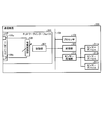
- FIG. 1 is a block diagram showing an example of a configuration of a communication device according to a first embodiment.
- the block diagram which shows an example of a function structure containing the software structure which operate
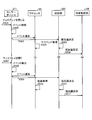
- the sequence diagram which shows the flow of the whole resistance control process in 1st Embodiment.
- the figure which shows an example of the network structure of the communication system containing a communication apparatus.
- the sequence diagram which shows an example of the apparatus control process which controls a communication apparatus using remote control software.
- the block diagram which shows an example of a structure of the communication apparatus concerning the modification 2 of 1st Embodiment provided with the integrated resistive element.
- the block diagram which shows an example of a structure using a some variable resistance part.
- the block diagram which shows an example of a structure using a some variable resistance part.
- the block diagram which shows an example of a structure of the communication apparatus concerning 2nd Embodiment.
- the block diagram which shows an example of a structure of the communication apparatus concerning the modification of 2nd Embodiment.
- the flowchart which shows the whole flow of the resistance control process in 2nd Embodiment.
- the communication apparatus includes a variable resistance element that can change a resistance value, and controls the resistance value of the variable resistance element to be changed according to an operation state.
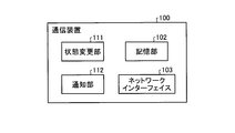
- FIG. 1 is a block diagram illustrating an example of a configuration of the communication device 100 according to the first embodiment.
- the communication device 100 includes a processor 101, a storage unit 102, a network interface 103, and a bus 104.
- the bus 104 is a bus that connects components such as the processor 101, the storage unit 102, and the network interface 103 to each other.
- the processor 101 controls the overall operation of the communication apparatus 100.
- the storage unit 102 stores software and data that operate on the processor 101.
- the storage unit 102 can be configured by any commonly used storage medium such as an HDD (Hard Disk Drive), an optical disk, a memory card, and a RAM (Random Access Memory).
- the network interface 103 is an interface for connecting the communication device 100 to a network to which an external device such as another communication device is connected.
- the network interface 103 includes a network port 105, a variable resistance unit 106, and a control unit 107.
- the network port 105 is a port (connection unit) for connecting a cable (not shown) physically connected to the network interface 103.
- the network port 105 includes a pair of pins 105 a and 105 b that are electrically connected to the variable resistance unit 106 so that the resistance value of the variable resistance unit 106 can be detected.
- the network port 105 is a LAN port compliant with Ethernet (registered trademark)
- any two of the eight pins can be used as the pins 105a and 105b.
- the variable resistance unit 106 is an electric resistance capable of setting a plurality of resistance values that change continuously or discontinuously.
- the variable resistance unit 106 can be configured by a variable resistance element such as a magnetic tunnel junction element (MTJ (Magnetic Tunnel) Junction) or a non-volatile digital potentiometer, for example.
- MTJ Magnetic Tunnel
- a non-volatile digital potentiometer for example.
- variable resistance unit 106 is connected to the network via the pins 105a and 105b of the network port 105, the set resistance value can be detected from an external device connected to the network. it can.
- the control unit 107 controls the variable resistance unit 106 so as to have a resistance value according to the operation state.
- the control unit 107 is designed in accordance with the property of the variable resistance unit 106 to be applied, and sets the resistance value of the variable resistance unit 106 to an appropriate value in accordance with an external control instruction.
- the control unit 107 receives, for example, the operation state of the communication device 100 as a control instruction, determines a resistance value according to the instructed operation state, and controls the variable resistance unit 106 so that the determined resistance value is obtained.
- the correspondence between the input operating state and the set resistance value in the control unit 107 may be implemented by a static combinational circuit as a fixed correspondence, or may be implemented by software or the like so that the correspondence can be changed.
- the resistance value corresponding to the suspended state may be configured to be changed to a resistance value indicated in some form instead of a fixed value determined at the time of design.
- the suspended state represents a state in which, for example, work contents are stored in a memory (not shown) and the operation is performed with the minimum power consumption for maintaining the work contents.
- FIG. 2 is a block diagram illustrating an example of a functional configuration including a software configuration that operates on the processor 101.
- the communication device 100 includes a state change unit 111 and a notification unit 112 as main software configurations in addition to the storage unit 102 and the network interface 103 which are part of the hardware configuration. .
- the state change unit 111 changes the operation state of the communication device 100. For example, the state changing unit 111 executes predetermined processing necessary to set the operation state of the communication apparatus 100 to the suspended state in accordance with a suspend request notified from other software (not shown).
- the notification unit 112 notifies the control unit 107 of the network interface 103 of the changed operation state changed by the state change unit 111 as a control instruction. As described above, the control unit 107 determines the resistance value of the variable resistance unit 106 according to the notified operation state.
- the control unit 107 may control the variable resistance unit 106 so that the notified resistance value is obtained.
- FIG. 3 is a sequence diagram showing the overall flow of the resistance control process in the first embodiment.
- the state changing unit 111 operating on the processor 101 detects a suspend request notified from an external processing unit such as other software (step S201). As a result, the state change unit 111 starts executing various processes (hereinafter referred to as a suspend process) necessary for shifting to the suspend state.
- a suspend process various processes
- the notification unit 112 operating on the processor 101 notifies the control unit 107 of a new state.
- the “suspend state” is notified to the control unit 107 as a new state (step S202).
- the control unit 107 derives a resistance value corresponding to the notified operating state using the correspondence relationship between the operating state and the resistance value mounted inside (step S203).
- the control unit 107 controls the variable resistance unit 106 to indicate the derived resistance value (step S204).
- the state changing unit 111 continues other suspend processing and finally shifts to the suspended state (step S205).
- the resistance value indicating that the variable resistance unit 106 is in the “suspended state” is held.
- another communication device connected via the network executes a process of inquiring the communication device 100 about the operation state, and detects the held resistance value, so that the operation state of the communication device 100 is “ Appropriate acquisition of “suspended state”.
- the return signal represents a signal requesting to return from the “suspend state” to the “normal operation state”. For example, a return event notified by the operating system or the like when a predetermined key is pressed during suspension corresponds to the return signal.
- the state changing unit 111 detects this return signal (step S206), and starts a process for returning to the “normal operation state” (hereinafter referred to as a return process) (step S207).
- the notification unit 112 notifies the control unit 107 of the “normal operation state” as a new state (step S208).
- the control unit 107 determines a resistance value corresponding to the “normal operation state” (step S209), and sets the resistance value of the variable resistance unit 106 (step S210).
- the other communication apparatuses execute processing for inquiring the operation state of the communication apparatus 100 and detect the held resistance value, whereby the operation state of the communication apparatus 100 is the “normal operation state”. Can be properly acquired.
- the communication apparatus 100 has been described as having two operation states of “suspend state” and “normal operation state”, but the operation state is not limited to these.
- an operation state such as “suspend state (Suspend-to-Disk or hibernation)” or “power-off state” may be represented.
- the number of operating states is not limited to two. For example, you may implement so that all the operation states of the above-mentioned "normal operation state”, “suspend”, “hibernation state”, and “power supply OFF" may be supported.
- the communication device 100 can be realized by, for example, a general personal computer.
- the applicable apparatus is not limited to this, and can be applied to any apparatus as long as it can be connected to a network.
- personal computer peripheral devices NAS (Network Attached Storage), printers, etc.
- information home appliances TVs, hard disk recorders, air conditioning, lighting, etc.
- security devices security cameras, electric locks, etc.
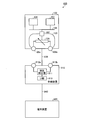
- FIG. 4 is a diagram illustrating an example of a network configuration of a communication system 400 including the communication device 100.
- the communication system 400 includes a communication device 100, a relay device 910, and a terminal device 920.
- the relay device 910 is a device having a function of detecting the operation state of the communication device 100.
- the relay device 910 and the communication device 100 are connected by a communication path 930 such as a wired LAN.
- the terminal device 920 is a device that actually attempts to acquire the operating state of the communication device 100 using the relay device 910.
- the terminal device 920 and the relay device 910 are connected by a communication path 940 such as a wired LAN or a wireless LAN.
- the relay device 910 includes a resistance detection unit 911, pins 912a and 912b of a network port (not shown), and a UI (user interface) unit 913 as main internal components.
- the resistance detection unit 911 detects the resistance value of the variable resistance unit 106 of the communication device 100 from a remote location.
- the pins 912a and 912b are a pair of pins corresponding to the pins 105a and 105b of the communication device 100 among the pins of the network port that connects the physical LAN cable.
- the UI unit 913 provides a user interface to the terminal device 920.
- the UI unit 913 may be realized by a dedicated circuit or device, may be realized by a general-purpose processor and software, or may be realized by combining them.
- the internal component of the terminal device 920 is not described, the same configuration as that of a general personal computer can be adopted.
- the communication path 930 and the communication path 940 connect network ports in accordance with a standard used such as IEEE 802.3, for example.
- the communication device 100 has the configuration shown in FIG. Therefore, the relay device 910 that is physically directly connected can detect the operation state of the communication device 100 by detecting the resistance value of the variable resistance unit 106 of the communication device 100.
- the relay apparatus 910 also includes a UI unit 913 that is a user interface function that enables operations from other devices.
- a description will be given on the assumption that a user interface is provided to a terminal device 920 including a Web server and a dedicated application using a Web browser or HTTP.
- the user interface function is not limited to this, and may be a character-based user interface or an interface using buttons or LEDs.
- the terminal device 920 is equipped with remote control software for operating the communication device 100 remotely.
- a user of the terminal device 920 operates the communication device 100 installed at a physically separated position using the remote control software.
- the remote control software has a function to display the operating status of the target communication device 100 (power ON, Wake on LAN compatible suspend, Wake on LAN non-compliant suspend, power OFF), and a power control function that matches the status.
- Wake on LAN means a function for starting an external device connected via a network via the network. Further, “Wake on LAN compatible suspend” represents a suspended state that can be restored by the Wake on LAN function. “Wake on LAN non-suspension suspend” represents a suspended state that cannot be restored by the Wake on LAN function.
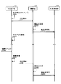
- FIG. 5 is a sequence diagram showing an example of a device control process for controlling the communication device 100 using the remote control software.
- control unit 107 operates according to the event notification (step S901), determines the resistance value of the variable resistor unit 106 to a value indicating “Wake on LAN suspend” (step S902), and sets it in the variable resistor unit 106 ( Step S903).
- variable resistor unit 106 among the rectangles at the bottom of the variable resistor unit 106, the shaded rectangles indicate that the variable resistor unit 106 is set in the “Wake on LAN compatible suspend” state. A rectangle without shading represents that the variable resistance unit 106 is set to the “power ON” state.
- a state confirmation event is generated (step S904).
- the terminal device 920 transmits a status confirmation request to the UI unit 913 (Web server) operating in the relay device 910 (step S905).
- the UI unit 913 Upon receiving the state confirmation request from the terminal device 920, the UI unit 913 requests the resistance detection unit 911 to acquire the resistance value of the variable resistance unit 106 of the communication device 100 based on the request (step S906).
- the resistance detection unit 911 applies a constant voltage or a current to the cable connected to the pins 912a and 912b of the network port of the relay device 910, thereby causing the variable resistance unit 106 built in the communication device 100 to A resistance value is detected (step S907).
- a shaded portion between the variable resistance unit 106 and the resistance detection unit 911 represents a resistance value detection period.
- the resistance detection unit 911 returns the detected resistance value to the UI unit 913 (step S908).
- the UI unit 913 returns a response to the terminal device 920 (step S909).
- the remote control software of the terminal device 920 that has acquired the operating state of the communication device 100 can indicate the acquired operating state to the user (step S910).
- the user can recognize that the communication apparatus 100 is in the “Wake on LAN compatible suspend” state.
- the remote control software selects a remote activation process that matches the state of the communication device 100 acquired in the previous step (step S912).
- the state is “Wake on LAN compatible suspend”
- the Wake on LAN activation process is selected and executed (step S913).
- a startup process is executed in the communication device 100 and the power is turned on (step S914).
- an event indicating that the power is turned on is notified to the control unit 107 (step S915).
- the control unit 107 determines a resistance value to be set (step S916), and sets the variable resistance unit 106 to the determined resistance value (step S917).
- the state of the communication device 100 is acquired from the terminal device 920 again, it can be correctly acquired that it is operating (power ON).
- the user can confirm that the display indicating the operation state of the communication apparatus 100 has been updated to “power ON”, and can access and operate the communication apparatus 100 appropriately. Even if it is impossible to access, since it is confirmed that the communication apparatus 100 has been started, troubleshooting is facilitated.
- the operation confirmation state of the communication apparatus 100 cannot be correctly determined by the state confirmation process (step S904).
- the state confirmation process For example, when suspending in a state that supports Wake on LAN, the power ON and suspend are treated as the same state (link up state), and the unit is suspended in a state that does not support Wake on LAN In this case, power OFF and suspend are treated as the same state (link down state). For this reason, it is not possible to determine which operating state it is without performing a startup process using Wake on LAN. That is, it is difficult to appropriately acquire the operation state of the communication device 100 from a remote location.
- the operation state of the communication apparatus 100 can be clearly distinguished as described above.
- the remote control software can accurately perform the activation process from a remote location only in the case of suspend corresponding to Wake on LAN.
- the system when the system is in a suspend state that does not support power OFF or Wake on LAN, it can display that fact and prompt the user to take another action. This improves user convenience.
- an appropriate activation method according to the operation state can be selected. For example, in the sequence of FIG. 5, since it was detected that the suspend corresponding to Wake on LAN was detected, the Wake on LAN activation process was executed. In addition, when it is detected that the power supply is not suspended or suspend on Wake on LAN, a mechanism that physically operates the power switch is operated, or a breaker that supplies electricity to the device is turned on. Or a process of sending a start signal for operating a dedicated electric circuit that controls the power supply or start-up process of the device can be executed.
- Modification 1 In the above description, the case where there is no difference between the actual operation state of the communication apparatus 100 and the resistance value of the variable resistance unit 106 has been described. However, it is not necessary to match the actual operation state with the operation state corresponding to the resistance value set in the variable resistance unit 106.
- the variable resistance unit 106 may be configured to exhibit a resistance value corresponding to a “suspend state” or a “power supply OFF state” even though the communication device 100 is in a normal operation state.
- variable resistance unit 106 is controlled to intentionally show a resistance value different from the operation state of the communication device 100.
- a packet that would otherwise be transmitted via the network can be configured not to reach the network interface 103 of the communication apparatus 100.
- variable resistance unit 106 when making a presentation on a notebook PC, it is not necessary to maintain the network connection. Therefore, in such a case, if the resistance value of the variable resistance unit 106 is set to a value corresponding to the “suspended state”, a packet is not transferred from the outside, and a reduction in power consumption can be expected. In addition, it is possible to prevent an incoming e-mail notification or an instant message incoming notification from being displayed during a presentation.
- the present invention can be applied to a case where processing is performed in which packets are transmitted and received in bursts and the network is not used thereafter, as in the case of referring to a Web page using a Web browser.
- the resistance value of the variable resistance unit 106 is changed to a value corresponding to the “suspended state”, thereby reducing the power consumption and wastefulness when the user is browsing the page. Packet arrival can be suppressed.
- variable resistance section 106 when software that expects to receive a packet is not operating, when it is operating but does not expect reception on a specific network interface, or when reception is not permitted by firewall software, etc. However, by intentionally changing the resistance value set in the variable resistance section 106, power consumption and arrival of useless packets can be suppressed.
- Such control can be realized by software operating on the processor 101.
- the notification unit 112 may be configured to notify the control unit 107 of the operation state specified by the user instead of the actual operation state. Further, for example, the notification unit 112 is configured to determine the operation state to be notified from the operation state of the communication apparatus 100 and the operation state of the software being executed, and to notify the control unit 107 of the determined operation state. May be.
- variable resistance unit 106 can be configured by a variable resistance element such as a magnetic tunnel junction element or a variable resistance device. In many cases, these elements and devices have an integrated resistance component and control interface.
- FIG. 6 is a block diagram illustrating an example of a configuration of the communication device 120 according to the second modification of the first embodiment including an integrated resistance element.
- the communication device 120 includes a processor 101, a storage unit 102, a network interface 123, and a bus 104.
- This modification is different from the first embodiment in that the network interface 123 includes a resistance element 128 including the variable resistance unit 106 and the control unit 107 according to the first embodiment. A control signal exchanged between the variable resistance unit 106 and the control unit 107 is processed inside the resistance element 128.
- the control unit 107 controls the direction of the magnetic field stored in the resistance element 128.
- a control method a general method for operating the MTJ element, such as a method of passing a current to a conductor close to the resistance element 128, can be used.
- Modification 3 When a desired resistance value cannot be obtained with one variable resistance unit 106, a plurality of variable resistance units may be combined and used. For example, it is known that an MTJ element takes two values, a high resistance value and a low resistance value. For this reason, when identifying three or more states using the MTJ element as a variable resistance element, it is necessary to arrange a plurality of MTJ elements in series to create a desired resistance value.
- FIG. 7 and 8 are block diagrams showing an example of a configuration using a plurality of variable resistance units.
- FIG. 7 shows an example in which the control unit and the variable resistance unit are mounted so as to correspond one-to-one.
- the three variable resistance units 106a to 106c are controlled by the control units 107a to 107c, respectively.
- FIG. 8 shows an example in which a plurality of variable resistance units are controlled by one control unit.
- an example is shown in which three variable resistance units 106 a to 106 c are controlled by one control unit 107.
- an operation for converting information generated inside the communication apparatus 100 for example, an instruction issued by the processor 101 or an event notification generated by the sensor
- information suitable for the input interface of the digital potentiometer operates on the processor 101. This may be done using software or a new dedicated conversion circuit.
- Modification 4 In the description so far, the operation state of the communication apparatus 100 has been expressed using a variable resistance element that looks logically one. This method has an advantage that the number of parts can be reduced, but the control of the resistance value requires strictness. Therefore, by using a variable resistance element and a reference resistance element that is an element having a predetermined resistance value as a reference, the operation state is changed by the difference in both resistance values or the potential difference or current difference generated by the difference in both resistance values. You may comprise so that it may detect. For example, it can be realized by connecting a reference resistance element to a certain pair of LAN cables and connecting a variable resistance element to another pair.
- the communication device 100 includes the variable resistance element that can change the resistance value, and can control to change the resistance value of the variable resistance element according to the operation state. it can. For this reason, it is possible to acquire various operation states that are changed according to the operation of the device from the external device while suppressing standby power for realizing confirmation of the operation state.
- the control program executed by the communication device 100 is a file in an installable or executable format, and is a CD-ROM (Compact Disk Read Only Memory), a flexible disk (FD), a CD-ROM. It is recorded on a computer-readable recording medium such as R (Compact Disk Recordable) and DVD (Digital Versatile Disk).
- CD-ROM Compact Disk Read Only Memory
- FD flexible disk
- CD-ROM Compact Disk Read Only Memory
- It is recorded on a computer-readable recording medium such as R (Compact Disk Recordable) and DVD (Digital Versatile Disk).
- the control program executed by the communication device 100 according to the first embodiment may be stored on a computer connected to a network such as the Internet and provided by being downloaded via the network. Good.
- the control program executed by the communication device 100 according to the first embodiment may be configured to be provided or distributed via a network such as the Internet.
- control program of the first embodiment may be provided by being incorporated in advance in a ROM or the like.
- the control program executed by the communication apparatus 100 according to the first embodiment has a module configuration including the above-described units (state change unit, notification unit), and the processor 101 stores the above-described memory as actual hardware.
- the above-described units are loaded onto the main storage device, and the above-described units are generated on the main storage device.
- the communication apparatus includes a sensor device that detects various types of information related to the operation state, and controls the resistance value of the variable resistance element to be changed according to the detection result.
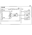
- FIG. 9 is a block diagram illustrating an example of a configuration of the communication device 200 according to the second embodiment.
- the communication device 200 includes a processor 101, a storage unit 102, a network interface 203, a bus 104, and a sensor device 211.
- FIG. 1 is a block diagram showing the configuration of the communication apparatus 100 according to the first embodiment, and thus are denoted by the same reference numerals and description thereof is omitted here.
- the sensor device 211 is a sensor that can detect a change in the operation state that occurs with respect to the communication device 200, or a sensor that requests a change in the operation state.
- the communication apparatus 200 is realized as a notebook PC
- an open / close sensor attached to a liquid crystal display of the notebook PC can be used as the sensor device 211.
- a current sensor that measures the current flowing into the processor 101
- a voltage sensor that measures the voltage of the processor 101
- a temperature sensor that measures the amount of heat generated by the processor 101
- a pressure sensor corresponding to the power button and the amount of light around the communication device
- a light sensor for recognizing sound or a sound sensor for recognizing sound may be used.
- the control unit 207 is different from the control unit 107 of the first embodiment in that the resistance value of the variable resistance unit 106 is set according to the detection result of the sensor device 211.
- the type and number of sensor devices to be mounted at the same time are not limited to one.
- a plurality of types of sensor devices may be mounted simultaneously, or a plurality of the same type of sensor devices may be mounted.
- FIG. 10 is a block diagram illustrating an example of the configuration of the communication apparatus 220 configured as described above.
- the communication device 220 includes a processor 101, a storage unit 102, a network interface 203, a bus 104, a plurality of sensor devices 211a to 211c, and a sensor processing unit 212.
- the sensor processing unit 212 functions as a determination unit that determines whether or not the operation state of the communication device 220 is changed from information output from the sensor devices 211a to 211c. If it is determined that the change is made, the sensor processing unit 212 notifies the control unit 207 of an appropriate signal corresponding to the changed operation state, instead of the sensor devices 211a to 211c.
- a configuration unit that collects information on each sensor device such as the sensor processing unit 212, is not essential.
- the control unit 207 may be configured to determine a resistance value to be set based on an input from each sensor device.
- the communication device 200 as shown in FIG. 9 is realized as a notebook PC and a sensor device 211 that is a sensor for detecting the open / closed state of the liquid crystal display of the notebook PC is attached will be described as an example.
- FIG. 11 is a flowchart showing an overall flow of resistance control processing in the second embodiment.
- step S501 the user of the notebook PC interrupts the operation and closes the display of the notebook PC.
- the sensor device 211 detects this operation (step S502).
- the sensor device 211 notifies the processor 101 and the control unit 207 that the display is closed (step S503).
- the processor 101 that has received this notification executes a suspend process by a process of software operating on the processor 101 (step S504). It should be noted that notification of such an event and execution of processing according to the event by the processor 101 are realized by a conventionally used method.
- control unit 207 determines a resistance value corresponding to the notified event (in this case, “the display is closed”) (step S505). Thereafter, the control unit 207 sets the resistance value determined by controlling the variable resistance unit 106 (step S506).
- the above is the flow of processing from detection of an event that causes a change in state to setting of a variable resistance value.
- a suspend process generated by software operating on the processor 101 and a resistance value change process by the control unit 207 are executed in parallel.
- the function of the sensor processing unit 212 may be realized by software operating on the processor 101.
- step S507 the operation of opening the display is the starting point.
- the sensor device 211 detects that the display has been opened (step S508), and notifies the processor 101 and the control unit 207 (step S509).
- the processor 101 Upon receiving this notification, the processor 101 executes a return process by software operating on the processor 101 (step S510). Similarly, the control unit 207 that has received the notification determines a resistance value corresponding to the notified event (in this case, “display has been opened”) (step S511). Thereafter, the control unit 207 sets the resistance value determined by controlling the variable resistance unit 106 (step S512).
- the open / close sensor is not used. Therefore, in the case of these devices, the temperature sensor, current sensor, voltage sensor, and the like of the processor 101 may be used. In this case, it should be noted that the event detected by the sensor does not cause a change in the operating state, but the sensor detects another physical change caused by the change in the operating state. For example, after suspend is executed by software operating on the processor 101, changes in parameters such as temperature, current, and voltage of the processor 101 are observed. Therefore, after the actual change in the operating state occurs (after step S504 or step S510) and after the physical change corresponding to the change in the operating state occurs, the resistance is changed according to the detected physical change. A process of changing the value (steps S502 to S506 or steps S508 to S512) may be executed.
- the communication device 200 includes a sensor device that detects various types of information related to the operation state, and can control to change the resistance value of the variable resistance element according to the detection result. it can. For this reason, it is possible to acquire various operation states that are changed according to the operation of the device from the external device while suppressing standby power for realizing confirmation of the operation state.
- the present invention is not limited to the above-described embodiment as it is, and can be embodied by modifying the constituent elements without departing from the scope of the invention in the implementation stage.
- various inventions can be formed by appropriately combining a plurality of constituent elements disclosed in the above embodiments. For example, some components may be deleted from all the components shown in the embodiment. Furthermore, constituent elements over different embodiments may be appropriately combined.
- Communication device 100, 120, 200, 220 Communication device 101 Processor 102 Storage unit 103, 123, 203 Network interface 104 Bus 105 Network port 105a, 105b Pin 106 Variable resistance unit 107, 207 Control unit 111 State change unit 112 Notification unit 128 Resistance element 211 Sensor device 212 Sensor processing unit 400 Communication system 910 Relay device 911 Resistance detection unit 912a, 912b Pin 913 UI unit 920 Terminal device 930, 940 Communication path
Landscapes
- Physics & Mathematics (AREA)
- General Physics & Mathematics (AREA)
- Small-Scale Networks (AREA)
- Power Sources (AREA)
- Dc Digital Transmission (AREA)
- Cable Transmission Systems, Equalization Of Radio And Reduction Of Echo (AREA)
Abstract
外部装置とネットワークを介して接続される通信装置100であって、ネットワークに接続するネットワークポート105と、外部装置から抵抗値を検出可能にネットワークポート105に接続され、抵抗値が可変である可変抵抗部106と、通信装置100の動作状態に応じた抵抗値に変更するように可変抵抗部106を制御する制御部107と、を備える。
Description
本発明は、ネットワークを構成する物理的な接続を共有する他の通信装置に対して状態を取得させる機能を具備する通信装置に関する。
従来、ネットワークに接続したノードの状態を確実に取得するためには、同ノードの動作を司るオペレーティングシステムなどのソフトウェアを介して行う方法が一般的であった。例えば、一方のノードからTCP/IPを用いて状態を問い合せるコマンドを送信し、それを受けたノードが内部状態に即した応答値を決定してTCP/IPを用いて返信する方法が知られている。
この方法は、TCP/IPの処理やそれを支えるデータリンク層が正しく稼働していることを前提としている。そのため、ノードが正常に動作している時しか状態を取得することができない。
この問題に対応するために、オペレーティングシステムが動作する第一のプロセッサに加えて消費電力が少ない第二のプロセッサを搭載し、第一のプロセッサの電源がOFFになっている間は、第二のプロセッサで動作する小規模なソフトウェアが代理応答したり、第一のプロセッサを起動したりする技術が提案されている(例えば、特許文献1)。
また、IEEE 802.3af規格や、特許文献2では、検出ノードとネットワークで接続された被検出ノード内の抵抗値の有無をネットワークを介して検出ノードから確認可能とする技術が提案されている。この方法によれば、遠隔から取得できる情報は限定されるが、抵抗値によって、被検出ノードがネットワークケーブルを介した給電を要求する装置であるか否かを検出することが可能となる。
しかしながら、特許文献1の方法では、第二のプロセッサを常に稼働状態にさせておく必要がある。このため、必要な電力消費量が増加するという問題や、プロセッサを複数搭載するためにコストが高くなるという問題があった。
また、特許文献2などの方法では、予め決められた固定の抵抗値を検出しているため、被検出ノードが、設計要件として事前に定められた固定的な状態であることを検出することしかできなかった。このため、例えば、被検出ノードが動的に変化する複数の状態のいずれであるかを判断することができなかった。
本発明は、上記に鑑みてなされたものであって、状態確認を実現するための待機電力を抑えつつ、装置の動作に応じて変更される多様な状態を外部装置から取得することができる通信装置を提供することを目的とする。
本発明は、外部装置とネットワークを介して接続される通信装置であって、前記ネットワークに接続する接続部と、前記外部装置から抵抗値を検出可能に前記接続部に接続され、前記抵抗値が可変である可変抵抗部と、動作状態に応じて前記抵抗値を変更する制御部と、を備えることを特徴とする。
本発明によれば、状態確認を実現するための待機電力を抑えつつ、装置の動作に応じて変更される多様な状態を外部装置から取得することができるという効果を奏する。
以下に添付図面を参照して、この発明にかかる通信装置、制御方法および制御プログラムの最良な実施の形態を詳細に説明する。
(第1の実施の形態)
第1の実施の形態にかかる通信装置は、抵抗値を変更可能な可変抵抗素子を備え、動作状態に応じて可変抵抗素子の抵抗値を変更するように制御する。
第1の実施の形態にかかる通信装置は、抵抗値を変更可能な可変抵抗素子を備え、動作状態に応じて可変抵抗素子の抵抗値を変更するように制御する。
図1は、第1の実施の形態にかかる通信装置100の構成の一例を示すブロック図である。図1に示すように、通信装置100は、プロセッサ101と、記憶部102と、ネットワークインターフェイス103と、バス104と、を備えている。
バス104は、プロセッサ101、記憶部102、およびネットワークインターフェイス103などの構成部を相互に接続するバスである。
プロセッサ101は、通信装置100の全体の動作を制御する。記憶部102は、プロセッサ101上で動作するソフトウェアやデータを格納する。なお、記憶部102は、HDD(Hard Disk Drive)、光ディスク、メモリカード、RAM(Random Access Memory)などの一般的に利用されているあらゆる記憶媒体により構成することができる。
ネットワークインターフェイス103は、通信装置100を、他の通信装置などの外部装置が接続されたネットワークと接続するためのインターフェイスである。ネットワークインターフェイス103は、ネットワークポート105と、可変抵抗部106と、制御部107とを備えている。
ネットワークポート105は、ネットワークインターフェイス103と物理的に接続するケーブル(図示せず)を接続するためのポート(接続部)である。ネットワークポート105は、可変抵抗部106の抵抗値を検出可能とするために可変抵抗部106と電気的に接続する一対のピン105a、105bを含んでいる。例えば、ネットワークポート105がイーサネット(登録商標)に準拠したLANポートの場合、8つのピンのうちいずれか2つをピン105a、105bとして利用するように構成することができる。
可変抵抗部106は、連続的または不連続的に変化する複数の抵抗値を設定可能な電気抵抗である。可変抵抗部106は、例えば、磁気トンネル接合素子(MTJ(Magnetic Tunnel Junction)素子)や不揮発性のデジタルポテンショメータなどの可変抵抗素子によって構成することができる。このように、可変抵抗部106は、素子単体で不揮発性を有し、変更された抵抗値を電源状態に依らずに保存できることが望ましい。
上述のように、可変抵抗部106は、ネットワークポート105のピン105a、105bを介してネットワークに接続されているため、当該ネットワークに接続された外部装置から、設定された抵抗値を検出することができる。
制御部107は、動作状態に応じた抵抗値となるように可変抵抗部106を制御する。制御部107は、適用する可変抵抗部106の性質に合わせて設計され、外部からの制御指示にしたがって可変抵抗部106の抵抗値を適切な値に設定する。
制御部107は、例えば、通信装置100の動作状態を制御指示として受付け、指示された動作状態に応じた抵抗値を決定し、決定した抵抗値となるように可変抵抗部106を制御する。
この場合、入力された動作状態と設定する抵抗値との対応関係を制御部107の内部に実装する必要がある。この関係は固定的な対応関係として静的な組み合わせ回路により実装しても良いし、対応関係を変更可能とするようにソフトウェアなどにより実装しても良い。例えば、サスペンド状態に対応する抵抗値を設計時に決められた固定値ではなく、何らかの形で指示された抵抗値に変更可能とするように構成してもよい。なお、サスペンド状態とは、例えば作業内容をメモリ(図示せず)に保存し、作業内容を維持する最小限の消費電力で動作する状態を表す。
本実施の形態では、プロセッサ101上で動作するソフトウェアが制御指示を発行する。図2は、プロセッサ101上で動作するソフトウェア構成を含む機能構成の一例を示すブロック図である。
同図に示すように、通信装置100は、ハードウェア構成の一部である記憶部102およびネットワークインターフェイス103のほか、主なソフトウェア構成として、状態変更部111と、通知部112とを備えている。
状態変更部111は、通信装置100の動作状態を変更する。状態変更部111は、例えば、他のソフトウェア(図示せず)から通知されたサスペンド要求にしたがい、通信装置100の動作状態をサスペンド状態にするために必要な所定の処理を実行する。
通知部112は、ネットワークインターフェイス103の制御部107に対して、状態変更部111によって変更される変更後の動作状態を制御指示として通知する。上述のように、制御部107は、通知された動作状態にしたがって可変抵抗部106の抵抗値を決定する。
なお、通知部112が、変更後の動作状態に応じた抵抗値を直接制御指示として通知するように構成してもよい。この場合は、制御部107は、通知された抵抗値となるように可変抵抗部106を制御すればよい。
次に、このように構成された第1の実施の形態にかかる通信装置100による抵抗制御処理について図3を用いて説明する。図3は、第1の実施の形態における抵抗制御処理の全体の流れを示すシーケンス図である。
同図は、通信装置100が通常通り動作している状態(以下、通常動作状態という)であることを仮定している。そして、同図のシーケンスでは、通信装置100が通常動作状態からサスペンド状態になった後、外部からの復帰要求を受けて、再び通常動作状態に戻るまでの流れを説明する。
プロセッサ101で動作する状態変更部111は、他のソフトウェアなどの外部の処理部から通知されたサスペンド要求を検出する(ステップS201)。これにより、状態変更部111は、サスペンド状態に移行するために必要な各種処理(以下、サスペンド処理という)の実行を開始する。
一連のサスペンド処理の中で、プロセッサ101で動作する通知部112が、制御部107に対して新しい状態を通知する。ここでは「サスペンド状態」を新しい状態として制御部107に通知する(ステップS202)。
制御部107は、内部に実装した動作状態と抵抗値との対応関係を用いて、通知された動作状態に応じた抵抗値を導出する(ステップS203)。抵抗値の導出を完了すると、制御部107は、導出した抵抗値を示すように可変抵抗部106を制御する(ステップS204)。その後、状態変更部111は、他のサスペンド処理を継続し、最終的にサスペンド状態へと移行する(ステップS205)。
この状態では、可変抵抗部106が「サスペンド状態」であることを示す抵抗値を保持している。このため、ネットワークを介して接続された他の通信装置は、通信装置100に対して動作状態を問い合せる処理を実行し、保持された抵抗値を検出することにより、通信装置100の動作状態が「サスペンド状態」であることを適切に取得できる。
次に、サスペンド中に、外部より復帰信号が通知されたとする。復帰信号とは、「サスペンド状態」から「通常動作状態」に復帰することを要求する信号を表す。例えばサスペンド中に所定のキーが押下されたときにオペレーティングシステム等により通知される復帰イベントが復帰信号に相当する。状態変更部111は、この復帰信号を検出し(ステップS206)、「通常動作状態」に復帰するための処理(以下、復帰処理という)を開始する(ステップS207)。
次に、通知部112が、制御部107に対して「通常動作状態」を新しい状態として通知する(ステップS208)。通知を受けた制御部107は、「通常動作状態」に対応する抵抗値を決定し(ステップS209)、可変抵抗部106の抵抗値を設定する(ステップS210)。
この状態では、可変抵抗部106が「通常動作状態」であることを示す抵抗値を保持している。このため、他の通信装置は、通信装置100に対して動作状態を問い合せる処理を実行し、保持された抵抗値を検出することにより、通信装置100の動作状態が「通常動作状態」であることを適切に取得できる。
なお、同図のシーケンスでは、通信装置100が「サスペンド状態」と「通常動作状態」の二つの動作状態を有する例を説明したが、動作状態はこれらに限られるものではない。例えば、「休止状態(Suspend to Disk、または、ハイバネーション)」、「電源OFF状態」といった動作状態を表しても良い。
また、動作状態の個数も二種類に限定されるものではない。例えば、上述の「通常動作状態」、「サスペンド」、「休止状態」、および「電源OFF」の全ての動作状態をサポートするように実装してもよい。
なお、通信装置100は、例えば一般的なパーソナルコンピュータなどにより実現できる。適用可能な装置はこれに限られるものではなく、ネットワークに接続可能な機器であれば、あらゆる機器に適用可能である。例えば、パーソナルコンピュータの周辺機器(NAS(Network Attached Storage)、プリンタなど)、情報家電機器(テレビ、ハードディスクレコーダ、空調、照明など)、および、ネットワークに接続するセキュリティ機器(防犯カメラ、電気錠など)にも適用できる。
次に、本実施の形態の通信装置100をネットワークの内部で使用する具体例を説明する。図4は、通信装置100を含む通信システム400のネットワーク構成の一例を示す図である。同図に示すように、通信システム400は、通信装置100と、中継装置910と、端末装置920とを含んでいる。
中継装置910は、通信装置100の動作状態を検出する機能を具備する装置である。中継装置910と通信装置100とは、有線LANなどの通信路930により接続されている。
端末装置920は、中継装置910を利用して実際に通信装置100の動作状態の取得を試みる装置である。端末装置920と中継装置910とは、有線LANまたは無線LANなどの通信路940により接続されている。
なお、同図では以降の説明に不要なその他の装置は省略している。より多くの端末装置や通信装置が接続していてもよい。
中継装置910は、主な内部構成要素として、抵抗検出部911と、ネットワークポート(図示せず)のピン912a、912bと、UI(ユーザインターフェイス)部913とを備えている。
抵抗検出部911は、通信装置100の可変抵抗部106の抵抗値を遠隔から検出する。ピン912a、912bは、物理的なLANケーブルを接続するネットワークポートのピンのうち、通信装置100のピン105a、105bにそれぞれ対応する1対のピンである。
UI部913は、端末装置920に対してユーザインターフェイスを提供する。UI部913は、専用の回路やデバイスで実現しても良いし、汎用プロセッサとソフトウェアにより実現しても良いし、それらを組み合わせた形で実現してもよい。
なお、端末装置920の内部構成要素は記載していないが、一般的なパーソナルコンピュータと同様の構成を採ることができる。
また、図面が煩雑になるため、通信装置100と中継装置910のネットワークポートを互いに接続する線は記載していない。通信路930および通信路940は、例えばIEEE 802.3などの利用する規格にしたがってネットワークポートを接続する。
通信装置100は、図1に示した構成を具備している。この為、物理的に直接接続している中継装置910は、通信装置100の可変抵抗部106の抵抗値を検出することで、通信装置100の動作状態を検出できる。また、中継装置910は他の機器からの操作を可能にするユーザインターフェイス機能であるUI部913を具備している。ここでは、Webサーバを備え、WebブラウザやHTTPを用いた専用アプリケーションを備えた端末装置920に対してユーザインターフェイスを提供するものとして説明する。ユーザインターフェイス機能はこれに限られず、キャラクタベースのユーザインターフェイス、および、ボタンやLEDによるインターフェイスなどでもよい。
端末装置920は、通信装置100を遠隔から操作するリモコンソフトウェアが搭載されていると仮定する。端末装置920の利用者は、このリモコンソフトウェアを用いて物理的に離れた位置に設置されている通信装置100を操作する。当該リモコンソフトウェアには、対象となる通信装置100の動作状態(電源ON、Wake on LAN対応サスペンド、Wake on LAN非対応サスペンド、電源OFF)を表示する機能、状態に合わせた電源制御機能が備わっているとする。
なお、Wake on LANとは、ネットワークを介して接続された外部の装置を、ネットワーク経由で起動する機能を意味する。また、「Wake on LAN対応サスペンド」とは、Wake on LAN機能によって復帰できるサスペンド状態を表す。そして、「Wake on LAN非対応サスペンド」とは、Wake on LAN機能によって復帰できないサスペンド状態を表す。
図5は、リモコンソフトウェアを用いて通信装置100を制御する装置制御処理の一例を示すシーケンス図である。
以下では、通信装置100は、Wake on LAN対応サスペンド状態であることを前提とする。すなわち、イベント通知に従って(ステップS901)制御部107が動作し、可変抵抗部106の抵抗値を「Wake on LAN対応サスペンド」を示す値に決定し(ステップS902)、可変抵抗部106に設定する(ステップS903)。
なお、同図では、可変抵抗部106の下部の矩形のうち、網掛けで表された矩形は、可変抵抗部106が「Wake on LAN対応サスペンド」状態に設定されていることを表す。また、網掛けなしの矩形は、可変抵抗部106が「電源ON」状態に設定されていることを表す。
端末装置920でリモコンソフトウェアを動作させると、状態確認イベントが発生する(ステップS904)。このイベントが発生すると、端末装置920は、中継装置910で動作するUI部913(Webサーバ)に向かって、状態確認要求を送信する(ステップS905)。
端末装置920からの状態確認要求を受け取ったUI部913は、当該要求に基づいて抵抗検出部911に対して通信装置100の可変抵抗部106の抵抗値の取得を要求する(ステップS906)。
抵抗検出部911は、中継装置910のネットワークポートのピン912a、912bに接続したケーブルに対して、一定の電圧を掛けたり電流を流したりして、通信装置100に内蔵された可変抵抗部106の抵抗値を検出する(ステップS907)。なお、可変抵抗部106と抵抗検出部911との間の網掛け部分が抵抗値の検出期間を表している。
検出期間が終了すると、抵抗検出部911は、検出した抵抗値をUI部913に返す(ステップS908)。同様に、UI部913は、端末装置920に対して応答を返す(ステップS909)。
一連の処理の結果、通信装置100の動作状態を入手した端末装置920のリモコンソフトウェアは、取得した動作状態を利用者に示すことができる(ステップS910)。その結果、利用者は、通信装置100が「Wake on LAN対応サスペンド」の状態であることを認識することができる。
ここで、利用者が、リモコンソフトウェアを用いて通信装置100の電源をONにする操作を行ったと仮定する(ステップS911)。その結果、リモコンソフトウェアは、先のステップにより取得した通信装置100の状態に合わせた遠隔起動処理を選択する(ステップS912)。ここでは「Wake on LAN対応サスペンド」の状態であることが判明しているので、Wake on LANの起動処理が選択され、実行される(ステップS913)。
その結果、通信装置100にて起動処理が実行されて電源がONになる(ステップS914)。その過程で、制御部107に対して電源がONされた旨を示すイベントが通知される(ステップS915)。その後、制御部107が、設定する抵抗値を決定し(ステップS916)、可変抵抗部106を決定した抵抗値に設定する(ステップS917)。
図5には記載していないが、このステップまで実行した後、再び端末装置920から通信装置100の状態を取得すれば、動作中(電源ON)であることが正しく取得できる。利用者は通信装置100の動作状態を表す表示が「電源ON」に更新されたことを確認し、適切に通信装置100に対してアクセスして操作することができる。また、万が一、アクセスできない場合であっても、通信装置100が起動したことを確認しているため、トラブルシュートが容易になる。
従来の方法では、状態確認処理(ステップS904)で、通信装置100の動作状態を正しく判断することができなかった。例えば、Wake on LANに対応した状態でサスペンドしている場合には、電源ONとサスペンドとが同一状態(リンクアップ状態)として扱われ、Wake on LANに対応していない状態でサスペンドしている場合には、電源OFFとサスペンドが同一状態(リンクダウン状態)として扱われていた。そのため、Wake on LANによる起動処理を行ってみなければいずれの動作状態であるかを判断できなかった。すなわち、遠隔から通信装置100の動作状態を適切に取得することが困難であった。
一方、本実施の形態の方法によれば、上述のように通信装置100の動作状態が明確に区別できるようになる。これによって、リモコンソフトウェアは、Wake on LANに対応したサスペンドの場合にのみ、遠隔から起動処理を的確に行うことができるようになる。また、電源OFFやWake on LANに対応しないサスペンド状態にある場合には、その旨を表示し、利用者に対して別の対処を促すことができる。これによって、ユーザの利便性が向上する。
さらに動作状態に応じて起動方法が異なるような通信装置100であれば、動作状態に応じた適切な起動方法を選択できるようになる。例えば、図5のシーケンスではWake on LANに対応したサスペンドであることを検出したので、Wake on LANの起動処理を実行した。この他、Wake on LANに対応しないサスペンドや電源OFFであることを検出した場合には、物理的に電源スイッチを操作するような機構を動作させたり、機器に対して電気を供給するブレーカをONにしたり、当該機器の電源や起動処理を司る専用の電気回路に働きかける起動信号を送出したりするなどの処理を実行させるように構成することができる。
(変形例1)
これまでの説明では、通信装置100の実際の動作状態と、可変抵抗部106の抵抗値との間に相違がない場合について述べた。しかし、実際の動作状態と、可変抵抗部106に設定する抵抗値に対応する動作状態とを一致させる必要はない。例えば、通信装置100が通常動作状態であるにもかかわらず、可変抵抗部106が「サスペンド状態」や「電源OFF状態」に相当する抵抗値を示すように構成してもよい。
これまでの説明では、通信装置100の実際の動作状態と、可変抵抗部106の抵抗値との間に相違がない場合について述べた。しかし、実際の動作状態と、可変抵抗部106に設定する抵抗値に対応する動作状態とを一致させる必要はない。例えば、通信装置100が通常動作状態であるにもかかわらず、可変抵抗部106が「サスペンド状態」や「電源OFF状態」に相当する抵抗値を示すように構成してもよい。
ここでは、通信装置100と接続された他の通信装置(対向ノード)が、可変抵抗部106の抵抗値の読み取りをサポートし、それに応じた通信制御を行っていると仮定する。本変形例では、この仮定の下で、意図的に通信装置100の動作状態と異なる抵抗値を示すように可変抵抗部106を制御する。これにより、例えば、本来であればネットワークを介して送信されてくるはずのパケットを、通信装置100のネットワークインターフェイス103に到達しなくなるように構成できる。この結果、ネットワークインターフェイス103や抵抗制御処理に要する電力の抑制、ネットワークを介した好ましくない動作の防止、および、プロセッサ101の能力を他の処理に振り分けるといったことが可能となる。
例えば、ノートPCでプレゼンテーションを行う場合、ネットワーク接続を維持し続ける必要はない。したがって、このような場合に、可変抵抗部106の抵抗値を「サスペンド状態」に対応する値に設定すれば、外部からパケットが転送されず消費電力の低減が期待できる。また、プレゼンテーション中に電子メールの着信通知が表示されたり、インスタントメッセージの着信通知が表示されるといったことを防止できる。
また、Webブラウザを用いてWebページを参照するときのように、バースト的にパケットを送受信し、その後はネットワークを使用しない処理が中心となる場合にも適用できる。Webブラウザの例では、ページをロードし終えたら可変抵抗部106の抵抗値を「サスペンド状態」に対応する値に変更することで、利用者がページを閲覧している時の消費電力や無駄なパケットの到達を抑制できる。
同様に、パケットの受信を期待するソフトウェアが動作していない場合、動作していても特定のネットワークインターフェイスでの受信を期待していない場合、および、ファイアウォールソフトウェアなどで受信を許可していない場合なども、意図的に可変抵抗部106に設定する抵抗値を変更することにより、消費電力や無駄なパケットの到達を抑制できる。
このような制御は、プロセッサ101上で動作するソフトウェアにより実現することができる。例えば、通知部112が、実際の動作状態ではなく、ユーザが指定した動作状態を制御部107に通知するように構成してもよい。また、例えば、通知部112が、通信装置100の動作状態と、実行しているソフトウェアの動作状態とから、通知する動作状態を決定し、決定した動作状態を制御部107に通知するように構成してもよい。
(変形例2)
上述のように、可変抵抗部106は磁気トンネル接合素子などの可変抵抗素子または可変抵抗デバイスによって構成できる。多くの場合、これらの素子やデバイスは抵抗成分と制御インターフェイスが一体化されている。
上述のように、可変抵抗部106は磁気トンネル接合素子などの可変抵抗素子または可変抵抗デバイスによって構成できる。多くの場合、これらの素子やデバイスは抵抗成分と制御インターフェイスが一体化されている。
図6は、一体化した抵抗素子を備える第1の実施の形態の変形例2にかかる通信装置120の構成の一例を示すブロック図である。同図に示すように、通信装置120は、プロセッサ101と、記憶部102と、ネットワークインターフェイス123と、バス104と、を備えている。
本変形例では、ネットワークインターフェイス123が、第1の実施の形態の可変抵抗部106と制御部107とを一体化して含む抵抗素子128を備える点が、第1の実施の形態と異なっている。可変抵抗部106と制御部107との間で交換される制御信号は、抵抗素子128の内部で処理される。
MTJ素子を用いる場合、制御部107は、抵抗素子128が記憶している磁界の向きを制御する。制御方法としては、抵抗素子128に近接する導体に対して電流を流す方法などの、MTJ素子を操作する一般的な方法が利用できる。
(変形例3)
一つの可変抵抗部106で所望の抵抗値が得られない場合、複数の可変抵抗部を結合して利用してもよい。例えばMTJ素子は高い抵抗値と低い抵抗値の二値をとることが知られている。このため、MTJ素子を可変抵抗素子として用いて3つ以上の状態を識別する場合には、複数のMTJ素子を直列に配置して所望の抵抗値を作りだす必要がある。
一つの可変抵抗部106で所望の抵抗値が得られない場合、複数の可変抵抗部を結合して利用してもよい。例えばMTJ素子は高い抵抗値と低い抵抗値の二値をとることが知られている。このため、MTJ素子を可変抵抗素子として用いて3つ以上の状態を識別する場合には、複数のMTJ素子を直列に配置して所望の抵抗値を作りだす必要がある。
図7および図8は、複数の可変抵抗部を用いる構成の一例を示すブロック図である。図7は、制御部と可変抵抗部とを一対一に対応するように実装する場合の例を示している。同図では、3つの可変抵抗部106a~106cが、それぞれ制御部107a~107cによって制御される例が示されている。
図8は、一つの制御部で複数の可変抵抗部を制御するように実装する場合の例を示している。同図では、3つの可変抵抗部106a~106cが、1つの制御部107によって制御される例が示されている。
なお、デジタルポテンショメータを利用する場合には、利用するデジタルポテンショメータの制御インターフェイスに合わせた形で接続する必要がある。例えば、シリアルやI2Cバスといった複雑な入力方法をサポートするものや、単純なパルス入力によるものなど様々な方法が存在する。
また汎用のデジタルポテンショメータを用いると、利用するシステムに依存するような抽象的なパラメータを受け付けるインターフェイスが利用できない場合がある。一般には抵抗値または抵抗値に直接的に対応するパラメータを入力として受け付けるインターフェイスが多い。
この場合、通信装置100の内部で発生する情報(例えばプロセッサ101が出す指示やセンサーが発生するイベント通知)から、デジタルポテンショメータの入力インターフェイスに合わせた情報に変換する作業は、プロセッサ101上で動作するソフトウェアや新たな専用の変換回路を用いて行えば良い。
(変形例4)
これまでの説明では、論理的に一つに見える可変抵抗素子を使って通信装置100の動作状態を表現していた。この方法は、部品点数が削減できる利点があるが、抵抗値の制御に厳密さが要求される。そこで、可変抵抗素子と、基準となる所定の抵抗値を有する素子である基準抵抗素子とを使い、両抵抗値の差、または、両抵抗値の差によって発生する電位差や電流差によって動作状態を検知するように構成してもよい。例えば、LANケーブルのある対に基準抵抗素子を接続し、別の対に可変抵抗素子を接続することで実現できる。
これまでの説明では、論理的に一つに見える可変抵抗素子を使って通信装置100の動作状態を表現していた。この方法は、部品点数が削減できる利点があるが、抵抗値の制御に厳密さが要求される。そこで、可変抵抗素子と、基準となる所定の抵抗値を有する素子である基準抵抗素子とを使い、両抵抗値の差、または、両抵抗値の差によって発生する電位差や電流差によって動作状態を検知するように構成してもよい。例えば、LANケーブルのある対に基準抵抗素子を接続し、別の対に可変抵抗素子を接続することで実現できる。
以上のように、第1の実施の形態にかかる通信装置100では、抵抗値を変更可能な可変抵抗素子を備え、動作状態に応じて可変抵抗素子の抵抗値を変更するように制御することができる。このため、動作状態の確認を実現するための待機電力を抑えつつ、装置の動作に応じて変更される多様な動作状態を外部装置から取得することが可能となる。
第1の実施の形態にかかる通信装置100で実行される制御プログラムは、インストール可能な形式又は実行可能な形式のファイルでCD-ROM(Compact Disk Read Only Memory)、フレキシブルディスク(FD)、CD-R(Compact Disk Recordable)、DVD(Digital Versatile Disk)等のコンピュータで読み取り可能な記録媒体に記録されて提供される。
また、第1の実施の形態にかかる通信装置100で実行される制御プログラムを、インターネット等のネットワークに接続されたコンピュータ上に格納し、ネットワーク経由でダウンロードさせることにより提供するように構成してもよい。また、第1の実施の形態にかかる通信装置100で実行される制御プログラムをインターネット等のネットワーク経由で提供または配布するように構成してもよい。
また、第1の実施の形態の制御プログラムを、ROM等に予め組み込んで提供するように構成してもよい。
第1の実施の形態にかかる通信装置100で実行される制御プログラムは、上述した各部(状態変更部、通知部)を含むモジュール構成となっており、実際のハードウェアとしてはプロセッサ101が上記記憶媒体から制御プログラムを読み出して実行することにより上記各部が主記憶装置上にロードされ、上述した各部が主記憶装置上に生成されるようになっている。
(第2の実施の形態)
第2の実施の形態にかかる通信装置は、動作状態に関する各種情報を検知するセンサーデバイスを備え、検出結果に応じて可変抵抗素子の抵抗値を変更するように制御する。
第2の実施の形態にかかる通信装置は、動作状態に関する各種情報を検知するセンサーデバイスを備え、検出結果に応じて可変抵抗素子の抵抗値を変更するように制御する。
図9は、第2の実施の形態にかかる通信装置200の構成の一例を示すブロック図である。図9に示すように、通信装置200は、プロセッサ101と、記憶部102と、ネットワークインターフェイス203と、バス104と、センサーデバイス211と、を備えている。
第2の実施の形態では、センサーデバイス211を追加したこと、および、ネットワークインターフェイス203内の制御部207の機能が第1の実施の形態と異なっている。その他の構成および機能は、第1の実施の形態にかかる通信装置100の構成を表すブロック図である図1と同様であるので、同一符号を付し、ここでの説明は省略する。
センサーデバイス211は、通信装置200に対して発生する動作状態の変更を検出できるセンサー、または動作状態の変更を要求するセンサーである。例えば、通信装置200がノートPCとして実現されている場合、ノートPCの液晶ディスプレイに取り付けられた開閉センサーをセンサーデバイス211とすることができる。その他、プロセッサ101に流入する電流を測定する電流センサー、プロセッサ101の電圧を測定する電圧センサー、プロセッサ101の発熱量を測定する温度センサー、および、電源ボタンに対応する圧力センサー、通信装置周辺の光量を認識する光センサーや音を認識する音センサーなどを用いるように構成してもよい。
制御部207は、センサーデバイス211の検知結果に応じて可変抵抗部106の抵抗値を設定する点が、第1の実施の形態の制御部107と異なっている。
なお、同図では1つのセンサーデバイスしか記載していないが、同時に搭載するセンサーデバイスの種類および数は1つに限定されない。複数の種類のセンサーデバイスを同時に搭載してもよいし、同じ種類のセンサーデバイスを複数搭載してもよい。
また、複数のセンサーデバイスを備え、各センサーデバイスからの情報にしたがって制御部207に通知する制御指示を決定するように構成部を備えるように構成してもよい。図10は、このように構成した通信装置220の構成の一例を示すブロック図である。図10に示すように、通信装置220は、プロセッサ101と、記憶部102と、ネットワークインターフェイス203と、バス104と、複数のセンサーデバイス211a~211cと、センサー処理部212と、を備えている。
センサー処理部212は、各センサーデバイス211a~211cが出力する情報から通信装置220の動作状態が変更されるか否かを判断する判断部として機能する。変更されると判断した場合は、センサー処理部212は、各センサーデバイス211a~211cに代わって、変更される動作状態に応じた適切な信号を制御部207へ通知する。
なお、複数のセンサーデバイスを活用する際に、センサー処理部212のように各センサーデバイスの情報を纏める構成部は必須ではない。例えば、制御部207が各センサーデバイスからの入力に基づいて設定すべき抵抗値を判断するように構成してもよい。
以下では、図9のような通信装置200をノートPCとして実現し、ノートPCの液晶ディスプレイの開閉状態を検出するセンサーであるセンサーデバイス211が取り付けられている場合を例に説明する。
次に、このように構成された第2の実施の形態にかかる通信装置200による抵抗制御処理について図11を用いて説明する。図11は、第2の実施の形態における抵抗制御処理の全体の流れを示すフローチャートである。
同図のシーケンスは、ノートPCを使用中の状態(通常動作状態)から開始されるものとする。
まず、ノートPCの利用者が作業を中断し、ノートPCのディスプレイを閉じたと仮定する(ステップS501)。センサーデバイス211は、この動作を検出する(ステップS502)。センサーデバイス211は、ディスプレイが閉じられたことをプロセッサ101および制御部207に通知する(ステップS503)。
この通知を受け取ったプロセッサ101は、プロセッサ101上で動作するソフトウェアの処理によってサスペンド処理を実行する(ステップS504)。なお、このようなイベントの通知およびプロセッサ101によるイベントに応じた処理の実行は、従来から用いられている方法により実現されるものとする。
一方、同通知を受けた制御部207は、通知されたイベント(この場合は「ディスプレイが閉じられた」)に対応する抵抗値を決定する(ステップS505)。その後、制御部207は、可変抵抗部106を制御して決定した抵抗値を設定する(ステップS506)。
以上が、状態の変化を引き起こすイベントを検出してから、可変抵抗値を設定するまでの処理の流れである。なお、本シーケンスではプロセッサ101上で動作するソフトウェアにより発生するサスペンド処理と、制御部207による抵抗値変更の処理が並行して実行されている。このように、本実施の形態では、既存のソフトウェアに変更を加えることなく、可変抵抗部106の制御を実現することが可能となる。すなわち、本実施の形態では、第1の実施の形態のように、プロセッサ101上で動作するソフトウェアによる制御を実行する必要がない。なお、第1の実施の形態と同様に、例えばセンサー処理部212の機能をプロセッサ101上で動作するソフトウェアにより実現するように構成してもよい。
引き続き、利用者が作業を再開する場合の処理について説明する。この場合、ディスプレイを開く動作が起点となる(ステップS507)。センサーデバイス211は、ディスプレイが開けられたことを検出し(ステップS508)、プロセッサ101および制御部207に通知する(ステップS509)。
この通知を受けたプロセッサ101は、プロセッサ101上で動作するソフトウェアによる復帰処理を実行する(ステップS510)。同様に通知を受けた制御部207は、通知されたイベント(この場合は「ディスプレイが開けられた」)に対応する抵抗値を決定する(ステップS511)。その後、制御部207は、可変抵抗部106を制御して決定した抵抗値を設定する(ステップS512)。
以上が、第2の実施の形態における抵抗制御処理のシーケンスである。本シーケンスではノートPCに取り付けられたディスプレイの開閉センサーを用いた例を述べたが、上述のように、他のセンサーを用いて実現してもよい。
例えば、デスクトップPCや情報家電機器の場合には、開閉センサーを利用しないと考えられる。そこで、これらの機器の場合は、プロセッサ101の温度センサー、電流センサー、および電圧センサーなどを利用するように構成してもよい。この場合、センサーが検出する事象が動作状態の変化を引き起こすものではなく、動作状態の変化によって発生する別の物理的変化を当該センサーが検出することに注意する必要がある。例えば、プロセッサ101上で動作するソフトウェアによりサスペンドが実行された後に、プロセッサ101の温度や電流・電圧といったパラメータの変化が観察される。したがって、実際の動作状態の変化が発生した後(ステップS504またはステップS510の後)であって、動作状態の変化に対応する物理的変化が発生した後に、検出された物理的変化に応じて抵抗値を変更する処理(ステップS502~ステップS506、または、ステップS508~ステップS512)を実行すればよい。
このように、第2の実施の形態にかかる通信装置200では、動作状態に関する各種情報を検知するセンサーデバイスを備え、検出結果に応じて可変抵抗素子の抵抗値を変更するように制御することができる。このため、動作状態の確認を実現するための待機電力を抑えつつ、装置の動作に応じて変更される多様な動作状態を外部装置から取得することが可能となる。
なお、本発明は、上記実施の形態そのままに限定されるものではなく、実施段階ではその要旨を逸脱しない範囲で構成要素を変形して具体化することができる。また、上記実施の形態に開示されている複数の構成要素の適宜な組み合わせにより、種々の発明を形成することができる。例えば、実施の形態に示される全構成要素からいくつかの構成要素を削除してもよい。さらに、異なる実施の形態にわたる構成要素を適宜組み合わせても良い。
100、120、200、220 通信装置
101 プロセッサ
102 記憶部
103、123、203 ネットワークインターフェイス
104 バス
105 ネットワークポート
105a、105b ピン
106 可変抵抗部
107、207 制御部
111 状態変更部
112 通知部
128 抵抗素子
211 センサーデバイス
212 センサー処理部
400 通信システム
910 中継装置
911 抵抗検出部
912a、912b ピン
913 UI部
920 端末装置
930、940 通信路
101 プロセッサ
102 記憶部
103、123、203 ネットワークインターフェイス
104 バス
105 ネットワークポート
105a、105b ピン
106 可変抵抗部
107、207 制御部
111 状態変更部
112 通知部
128 抵抗素子
211 センサーデバイス
212 センサー処理部
400 通信システム
910 中継装置
911 抵抗検出部
912a、912b ピン
913 UI部
920 端末装置
930、940 通信路
Claims (8)
- 外部装置とネットワークを介して接続される通信装置であって、
前記ネットワークに接続する接続部と、
前記外部装置から抵抗値を検出可能に前記接続部に接続され、前記抵抗値が可変である可変抵抗部と、
動作状態に応じて前記抵抗値を変更する制御部と、
を備えることを特徴とする通信装置。 - 前記動作状態を変更する状態変更部をさらに備え、
前記制御部は、変更後の前記動作状態に応じて前記抵抗値を変更すること、
を特徴とする請求項1に記載の通信装置。 - 変更後の前記動作状態を前記制御部に通知する通知部をさらに備え、
前記制御部は、通知された前記動作状態に応じて前記抵抗値を変更すること、
を特徴とする請求項2に記載の通信装置。 - 変更後の前記動作状態に応じた前記抵抗値を前記制御部に通知する通知部をさらに備え、
前記制御部は、前記可変抵抗部を通知された前記抵抗値に変更すること、
を特徴とする請求項2に記載の通信装置。 - 前記動作状態の変化に応じて前記通信装置に生じる物理的変化を検知する検知部をさらに備え、
前記制御部は、検知された前記物理的変化に応じて前記抵抗値を変更すること、
を特徴とする請求項1に記載の通信装置。 - 検知された前記物理的変化に基づいて前記抵抗値を変更するか否かを判断する判断部をさらに備え、
前記制御部は、前記抵抗値を変更すると判断された場合に、検知された前記物理的変化に応じて前記抵抗値を変更すること、
を特徴とする請求項5に記載の通信装置。 - 前記可変抵抗部は複数備えられ、
前記制御部は、複数の前記可変抵抗部それぞれを、前記動作状態に応じた前記抵抗値に変更すること、
を特徴とする請求項3に記載の通信装置。 - 前記制御部は、複数の前記可変抵抗部それぞれに対応して1つずつ備えられ、対応する前記可変抵抗部を前記動作状態に応じた前記抵抗値に変更すること、
を特徴とする請求項7に記載の通信装置。
Priority Applications (1)
| Application Number | Priority Date | Filing Date | Title |
|---|---|---|---|
| US13/186,545 US20120011356A1 (en) | 2009-01-21 | 2011-07-20 | Communication device |
Applications Claiming Priority (2)
| Application Number | Priority Date | Filing Date | Title |
|---|---|---|---|
| JP2009-011271 | 2009-01-21 | ||
| JP2009011271A JP2010171643A (ja) | 2009-01-21 | 2009-01-21 | 通信装置、制御方法および制御プログラム |
Related Child Applications (1)
| Application Number | Title | Priority Date | Filing Date |
|---|---|---|---|
| US13/186,545 Continuation US20120011356A1 (en) | 2009-01-21 | 2011-07-20 | Communication device |
Publications (1)
| Publication Number | Publication Date |
|---|---|
| WO2010084795A1 true WO2010084795A1 (ja) | 2010-07-29 |
Family
ID=42355849
Family Applications (1)
| Application Number | Title | Priority Date | Filing Date |
|---|---|---|---|
| PCT/JP2010/050181 Ceased WO2010084795A1 (ja) | 2009-01-21 | 2010-01-08 | 通信装置 |
Country Status (3)
| Country | Link |
|---|---|
| US (1) | US20120011356A1 (ja) |
| JP (1) | JP2010171643A (ja) |
| WO (1) | WO2010084795A1 (ja) |
Cited By (1)
| Publication number | Priority date | Publication date | Assignee | Title |
|---|---|---|---|---|
| US8588247B2 (en) | 2009-01-16 | 2013-11-19 | Kabushiki Kaisha Toshiba | Relay device and remote startup system |
Citations (3)
| Publication number | Priority date | Publication date | Assignee | Title |
|---|---|---|---|---|
| JPH0997681A (ja) * | 1995-09-29 | 1997-04-08 | Matsushita Electric Works Ltd | 照明装置 |
| JP2001282181A (ja) * | 2000-03-29 | 2001-10-12 | Fujitsu Hitachi Plasma Display Ltd | プラズマディスプレイ装置及びその製造方法 |
| JP2003108349A (ja) * | 2001-09-28 | 2003-04-11 | Kyocera Mita Corp | 画像形成装置のモニタシステム |
Family Cites Families (1)
| Publication number | Priority date | Publication date | Assignee | Title |
|---|---|---|---|---|
| JP2004063161A (ja) * | 2002-07-26 | 2004-02-26 | Matsushita Electric Works Ltd | 照明制御システム |
-
2009
- 2009-01-21 JP JP2009011271A patent/JP2010171643A/ja active Pending
-
2010
- 2010-01-08 WO PCT/JP2010/050181 patent/WO2010084795A1/ja not_active Ceased
-
2011
- 2011-07-20 US US13/186,545 patent/US20120011356A1/en not_active Abandoned
Patent Citations (3)
| Publication number | Priority date | Publication date | Assignee | Title |
|---|---|---|---|---|
| JPH0997681A (ja) * | 1995-09-29 | 1997-04-08 | Matsushita Electric Works Ltd | 照明装置 |
| JP2001282181A (ja) * | 2000-03-29 | 2001-10-12 | Fujitsu Hitachi Plasma Display Ltd | プラズマディスプレイ装置及びその製造方法 |
| JP2003108349A (ja) * | 2001-09-28 | 2003-04-11 | Kyocera Mita Corp | 画像形成装置のモニタシステム |
Cited By (1)
| Publication number | Priority date | Publication date | Assignee | Title |
|---|---|---|---|---|
| US8588247B2 (en) | 2009-01-16 | 2013-11-19 | Kabushiki Kaisha Toshiba | Relay device and remote startup system |
Also Published As
| Publication number | Publication date |
|---|---|
| JP2010171643A (ja) | 2010-08-05 |
| US20120011356A1 (en) | 2012-01-12 |
Similar Documents
| Publication | Publication Date | Title |
|---|---|---|
| EP3358850B1 (en) | Content playing apparatus, method for providing ui of content playing apparatus, network server, and method for controlling by network server | |
| US20150036178A1 (en) | Method of controlling communication system | |
| JP6727798B2 (ja) | 情報処理装置及びその制御方法、並びにプログラム | |
| US20140380032A1 (en) | Electronic device, method for controlling electronic device, and program | |
| JP6476675B2 (ja) | 画像処理装置、画像処理システム及びプログラム | |
| JP5958177B2 (ja) | 電子機器起動制御装置、電子機器起動制御システム、および電子機器起動制御方法、並びにプログラム | |
| JP5890648B2 (ja) | 情報処理装置、その制御方法、およびデバイス制御システム | |
| JP2016103863A (ja) | 制御装置、機器操作システム、制御方法及びプログラム | |
| JP2010171643A (ja) | 通信装置、制御方法および制御プログラム | |
| EP3208720B1 (en) | Display device and method for implementing new-connection notification function for mhl signal source | |
| JP2011100231A (ja) | 切替装置、表示装置、動作制御方法及びプログラム | |
| JP6281122B2 (ja) | 情報処理装置 | |
| EP2849432A1 (en) | Relay device | |
| US10659306B2 (en) | Information processing device and method for setting the environment of the device | |
| US20070064268A1 (en) | Image forming apparatus, control method therefor, program, and image forming system | |
| EP3709202A1 (en) | Electronic apparatus enabling omission of software tampering detection processing at activation | |
| JP2010154273A (ja) | 遠隔制御装置及び遠隔制御方法 | |
| JP6417539B2 (ja) | 情報処理装置 | |
| JPWO2007026615A1 (ja) | 情報処理装置、テレビジョン放送受信機、及びテレビジョン放送記録再生機 | |
| JP5216461B2 (ja) | モータ制御装置および画像形成装置 | |
| JP5312809B2 (ja) | 画面表示装置 | |
| US11533410B2 (en) | Information processing apparatus and non-transitory computer readable medium storing program to perform arithmetic operation by using connected arithmetic device | |
| JP7346862B2 (ja) | 情報処理装置、システム、及びプログラム | |
| JP2010030128A (ja) | 画像形成装置および画像形成システム | |
| JP2025182885A (ja) | 情報処理装置及び設定方法 |
Legal Events
| Date | Code | Title | Description |
|---|---|---|---|
| 121 | Ep: the epo has been informed by wipo that ep was designated in this application |
Ref document number: 10733402 Country of ref document: EP Kind code of ref document: A1 |
|
| NENP | Non-entry into the national phase |
Ref country code: DE |
|
| 122 | Ep: pct application non-entry in european phase |
Ref document number: 10733402 Country of ref document: EP Kind code of ref document: A1 |