WO2010082623A1 - Process for producing polymeric electrolyte membrane - Google Patents
Process for producing polymeric electrolyte membrane Download PDFInfo
- Publication number
- WO2010082623A1 WO2010082623A1 PCT/JP2010/050403 JP2010050403W WO2010082623A1 WO 2010082623 A1 WO2010082623 A1 WO 2010082623A1 JP 2010050403 W JP2010050403 W JP 2010050403W WO 2010082623 A1 WO2010082623 A1 WO 2010082623A1
- Authority
- WO
- WIPO (PCT)
- Prior art keywords
- electrolyte membrane
- film
- polymer electrolyte
- solution
- substrate
- Prior art date
Links
Images


Classifications
-
- C—CHEMISTRY; METALLURGY
- C08—ORGANIC MACROMOLECULAR COMPOUNDS; THEIR PREPARATION OR CHEMICAL WORKING-UP; COMPOSITIONS BASED THEREON
- C08J—WORKING-UP; GENERAL PROCESSES OF COMPOUNDING; AFTER-TREATMENT NOT COVERED BY SUBCLASSES C08B, C08C, C08F, C08G or C08H
- C08J5/00—Manufacture of articles or shaped materials containing macromolecular substances
- C08J5/20—Manufacture of shaped structures of ion-exchange resins
- C08J5/22—Films, membranes or diaphragms
- C08J5/2206—Films, membranes or diaphragms based on organic and/or inorganic macromolecular compounds
- C08J5/2218—Synthetic macromolecular compounds
- C08J5/2256—Synthetic macromolecular compounds based on macromolecular compounds obtained by reactions other than those involving carbon-to-carbon bonds, e.g. obtained by polycondensation
-
- H—ELECTRICITY
- H01—ELECTRIC ELEMENTS
- H01M—PROCESSES OR MEANS, e.g. BATTERIES, FOR THE DIRECT CONVERSION OF CHEMICAL ENERGY INTO ELECTRICAL ENERGY
- H01M8/00—Fuel cells; Manufacture thereof
- H01M8/10—Fuel cells with solid electrolytes
- H01M8/1016—Fuel cells with solid electrolytes characterised by the electrolyte material
- H01M8/1018—Polymeric electrolyte materials
- H01M8/1069—Polymeric electrolyte materials characterised by the manufacturing processes
- H01M8/1081—Polymeric electrolyte materials characterised by the manufacturing processes starting from solutions, dispersions or slurries exclusively of polymers
-
- H—ELECTRICITY
- H01—ELECTRIC ELEMENTS
- H01M—PROCESSES OR MEANS, e.g. BATTERIES, FOR THE DIRECT CONVERSION OF CHEMICAL ENERGY INTO ELECTRICAL ENERGY
- H01M8/00—Fuel cells; Manufacture thereof
- H01M8/02—Details
-
- H—ELECTRICITY
- H01—ELECTRIC ELEMENTS
- H01M—PROCESSES OR MEANS, e.g. BATTERIES, FOR THE DIRECT CONVERSION OF CHEMICAL ENERGY INTO ELECTRICAL ENERGY
- H01M8/00—Fuel cells; Manufacture thereof
- H01M8/10—Fuel cells with solid electrolytes
- H01M8/1016—Fuel cells with solid electrolytes characterised by the electrolyte material
- H01M8/1018—Polymeric electrolyte materials
- H01M8/102—Polymeric electrolyte materials characterised by the chemical structure of the main chain of the ion-conducting polymer
- H01M8/1023—Polymeric electrolyte materials characterised by the chemical structure of the main chain of the ion-conducting polymer having only carbon, e.g. polyarylenes, polystyrenes or polybutadiene-styrenes
-
- H—ELECTRICITY
- H01—ELECTRIC ELEMENTS
- H01M—PROCESSES OR MEANS, e.g. BATTERIES, FOR THE DIRECT CONVERSION OF CHEMICAL ENERGY INTO ELECTRICAL ENERGY
- H01M8/00—Fuel cells; Manufacture thereof
- H01M8/10—Fuel cells with solid electrolytes
- H01M8/1016—Fuel cells with solid electrolytes characterised by the electrolyte material
- H01M8/1018—Polymeric electrolyte materials
- H01M8/1067—Polymeric electrolyte materials characterised by their physical properties, e.g. porosity, ionic conductivity or thickness
-
- H—ELECTRICITY
- H01—ELECTRIC ELEMENTS
- H01M—PROCESSES OR MEANS, e.g. BATTERIES, FOR THE DIRECT CONVERSION OF CHEMICAL ENERGY INTO ELECTRICAL ENERGY
- H01M8/00—Fuel cells; Manufacture thereof
- H01M8/10—Fuel cells with solid electrolytes
- H01M8/1016—Fuel cells with solid electrolytes characterised by the electrolyte material
- H01M8/1018—Polymeric electrolyte materials
- H01M8/1069—Polymeric electrolyte materials characterised by the manufacturing processes
- H01M8/1079—Inducing porosity into non porous precursors membranes, e.g. leaching, pore stretching
-
- C—CHEMISTRY; METALLURGY
- C08—ORGANIC MACROMOLECULAR COMPOUNDS; THEIR PREPARATION OR CHEMICAL WORKING-UP; COMPOSITIONS BASED THEREON
- C08J—WORKING-UP; GENERAL PROCESSES OF COMPOUNDING; AFTER-TREATMENT NOT COVERED BY SUBCLASSES C08B, C08C, C08F, C08G or C08H
- C08J2371/00—Characterised by the use of polyethers obtained by reactions forming an ether link in the main chain; Derivatives of such polymers
- C08J2371/08—Polyethers derived from hydroxy compounds or from their metallic derivatives
- C08J2371/10—Polyethers derived from hydroxy compounds or from their metallic derivatives from phenols
-
- Y—GENERAL TAGGING OF NEW TECHNOLOGICAL DEVELOPMENTS; GENERAL TAGGING OF CROSS-SECTIONAL TECHNOLOGIES SPANNING OVER SEVERAL SECTIONS OF THE IPC; TECHNICAL SUBJECTS COVERED BY FORMER USPC CROSS-REFERENCE ART COLLECTIONS [XRACs] AND DIGESTS
- Y02—TECHNOLOGIES OR APPLICATIONS FOR MITIGATION OR ADAPTATION AGAINST CLIMATE CHANGE
- Y02E—REDUCTION OF GREENHOUSE GAS [GHG] EMISSIONS, RELATED TO ENERGY GENERATION, TRANSMISSION OR DISTRIBUTION
- Y02E60/00—Enabling technologies; Technologies with a potential or indirect contribution to GHG emissions mitigation
- Y02E60/30—Hydrogen technology
- Y02E60/50—Fuel cells
-
- Y—GENERAL TAGGING OF NEW TECHNOLOGICAL DEVELOPMENTS; GENERAL TAGGING OF CROSS-SECTIONAL TECHNOLOGIES SPANNING OVER SEVERAL SECTIONS OF THE IPC; TECHNICAL SUBJECTS COVERED BY FORMER USPC CROSS-REFERENCE ART COLLECTIONS [XRACs] AND DIGESTS
- Y02—TECHNOLOGIES OR APPLICATIONS FOR MITIGATION OR ADAPTATION AGAINST CLIMATE CHANGE
- Y02P—CLIMATE CHANGE MITIGATION TECHNOLOGIES IN THE PRODUCTION OR PROCESSING OF GOODS
- Y02P20/00—Technologies relating to chemical industry
- Y02P20/50—Improvements relating to the production of bulk chemicals
- Y02P20/582—Recycling of unreacted starting or intermediate materials
-
- Y—GENERAL TAGGING OF NEW TECHNOLOGICAL DEVELOPMENTS; GENERAL TAGGING OF CROSS-SECTIONAL TECHNOLOGIES SPANNING OVER SEVERAL SECTIONS OF THE IPC; TECHNICAL SUBJECTS COVERED BY FORMER USPC CROSS-REFERENCE ART COLLECTIONS [XRACs] AND DIGESTS
- Y02—TECHNOLOGIES OR APPLICATIONS FOR MITIGATION OR ADAPTATION AGAINST CLIMATE CHANGE
- Y02P—CLIMATE CHANGE MITIGATION TECHNOLOGIES IN THE PRODUCTION OR PROCESSING OF GOODS
- Y02P70/00—Climate change mitigation technologies in the production process for final industrial or consumer products
- Y02P70/50—Manufacturing or production processes characterised by the final manufactured product
Definitions
- the present invention relates to a method for producing a polymer electrolyte membrane.
- a fuel cell is a kind of power generation device that extracts electric energy by electrochemically oxidizing a fuel such as hydrogen or methanol, and has recently attracted attention as a clean energy supply source.
- the polymer electrolyte fuel cell has a low standard operating temperature of around 100 ° C. and a high energy density, so that it is a relatively small-scale distributed power generation facility, a mobile power generator such as an automobile or a ship.
- a mobile power generator such as an automobile or a ship.
- secondary batteries such as nickel metal hydride batteries and lithium ion batteries.
- an anode electrode and a cathode electrode in which a reaction responsible for power generation occurs, and a polymer electrolyte membrane serving as a proton conductor between the anode and the cathode are sometimes referred to as a membrane electrode assembly (hereinafter, abbreviated as MEA).
- MEA membrane electrode assembly
- a cell in which this MEA is sandwiched between separators is configured as a unit.
- the polymer electrolyte membrane is mainly composed of a polymer electrolyte material.
- the polymer electrolyte material is also used as a binder for the electrode catalyst layer.
- aromatic polyetheretherketone As polyelectrolyte materials, aromatic polyetheretherketone, aromatic polyetherketone and aromatic polyethersulfone have been particularly actively studied from the viewpoint of heat resistance and chemical stability.
- PEK aromatic polyether ketones
- Victrex PEEK-HT manufactured by Victrex
- Patent Documents 1 and 2 A polymer having a low sulfonic acid group density composition due to its high crystallinity has the problem that crystals remain insoluble in a solvent due to residual crystals, resulting in poor processability.
- the sulfonic acid group density is increased to improve processability, Since the polymer was not crystalline, it swelled significantly in water, making it very difficult to purify the polymer and making it difficult to manufacture.
- the polymer electrolyte material according to the prior art is insufficient as a means for improving economy, workability, proton conductivity, fuel crossover, mechanical strength, and long-term durability, and is an industrially useful fuel cell. It could not be a polymer electrolyte material for use.
- Patent Document 4 discloses a method in which a protective group (hydrolyzable solubility-imparting group) is introduced into a polymer having crystallization ability to form a solution, and after the film formation, the solution is deprotected (hydrolyzed). Proposed, improved mechanical properties, improved chemical structure and relationship between hot water, heat resistant methanol, processability, etc., excellent proton conductivity, fuel cutoff, mechanical strength, hot water, heat resistant methanol, processing It is said that it is possible to provide an electrolyte membrane having excellent properties and chemical stability. However, further improvements have been desired.
- Patent Document 5 proposes an electrolyte membrane reinforced with a porous film and having excellent conductivity and durability.
- Patent Document 5 discloses a composite membrane in which a fluorine-based microporous membrane is filled with a fluorine-based electrolyte membrane, and the exchange capacity of the electrolyte membrane used in the examples is 1.25 meq / g.
- proton conductivity as a composite polymer electrolyte membrane is insufficient, and further, since the constituent polymer is fluorine-based, hydrogen gas easily permeates, and the durability of the open circuit state when operated as a fuel cell is insufficient. It was.
- an electrolyte polymer having an ionic group density of 2.0 mmol / g or more is often synthesized by demineralization polycondensation, and during isolation and purification, a large amount of polymerization solution is used to remove the by-product salt.
- the solution is poured into water for precipitation purification, dried, redissolved and used as a solution coating solution.
- the electrolyte polymers having an ionic group density of 2.0 mmol / g or more are dissolved in water or extremely swelled. Has been found to be very difficult to purify and isolate the polymer.
- the method for producing a polymer electrolyte membrane of the present invention removes a part of the salt generated during polycondensation directly from a polymer electrolyte polymerization solution having an ionic group density of 2 mmol / g or more by centrifugation.
- an electrolyte polymer having an ionic group density of 2 mmol / g or more it is possible to industrially purify an electrolyte polymer having an ionic group density of 2 mmol / g or more, and an electrolyte membrane having an ionic group density of 2 mmol / g or more can be obtained.
- an electrolyte membrane having an ionic group density of 2 mmol / g or more can be obtained.
- the composite polymer electrolyte membrane using the electrolyte polymer it is possible to realize a fuel cell having excellent high-temperature and low-humidity power generation performance and excellent durability.
- the method for producing a polymer electrolyte membrane according to the invention is a coating liquid in which a part of salt generated during polycondensation is directly removed from a polymer electrolyte polymerization solution having an ionic group density of 2 mmol / g or more by centrifugation. The process of obtaining.
- the polycondensation of the present invention is not particularly limited, and a method generally used in polymer synthesis can be used.
- a diol-terminated monomer is substituted with an alkali metal, reacted with a dihalide-terminated monomer, polymerized with desalting, or generated when a diamine-containing monomer and a dicarboxylic acid-chloride monomer are polymerized.
- a reaction in which an acid is neutralized with an alkali metal and salt is indirectly generated can be mentioned.
- it is suitable for a polymerization system in which a salt formed as a by-product is hardly soluble in a polymerization solvent and is precipitated as a solid.
- polycondensation it can also be preferably used to remove a salt by-produced by a coupling reaction between a dihalide and a Zn salt. Furthermore, it is also effective for a system in which an additive or residual monomer insoluble in the polymerization solvent is present.
- the term “directly” as used herein refers to a method in which a polymer is precipitated in water or in a solvent by contacting with a large amount of solvent in which the by-product salt is soluble but the polymer is insoluble, for example, water, methanol, acetone, toluene, hexane or the like. Instead, it means that the insoluble by-product salt produced is solid-liquid separated by centrifuging the polymerization solution as it is. At this time, the polymerization solution may be diluted with a solvent or the like in which the polymer electrolyte is soluble, and it is preferable to adjust the viscosity of the polymerization solution in consideration of the efficiency of the centrifugation operation.
- the ionic group is not particularly limited as long as it is a negatively charged atomic group, but is preferably one having a proton exchange ability.
- a functional group a sulfonic acid group, a sulfonimide group, a sulfuric acid group, a phosphonic acid group, a phosphoric acid group, and a carboxylic acid group are preferably used.
- Such an ionic group includes a case where it is a salt.
- the cation forming the salt include an arbitrary metal cation, NR 4+ (R is an arbitrary organic group), and the like.
- the valence and the like are not particularly limited and can be used.
- preferred metal ions include Li, Na, K, Rb, Cs, Mg, Ca, Sr, Ba, Ti, V, Mn, Al, Fe, Co, Ni, Cu, Zn, Zr, Mo, W, Pt, Rh, Ru, Ir, Pd, etc. are mentioned.
- Li, Na, K, Ca, Sr, and Ba are more preferable, and among them, Na and K that are inexpensive and can be easily proton-substituted without adversely affecting the solubility are more preferably used.
- the ionic group may be substituted with an ester or the like.
- ionic groups can be contained in two or more kinds in the polymer electrolyte material, and may be preferable by combining them.
- the combination is appropriately determined depending on the structure of the polymer. Among them, it is more preferable to have at least a sulfonic acid group, a sulfonimide group, and a sulfuric acid group from the viewpoint of high proton conductivity, and most preferable to have at least a sulfonic acid group from the viewpoint of hydrolysis resistance.
- simplification of the water management system is considered important for full-scale spread of fuel cells for automobiles and household fuel cells, and power generation conditions are high temperatures exceeding 80 ° C. and low humidification conditions with a relative humidity of 60% or less. Become. Therefore, an ionic group density of 2 mmol / g or more is essential for the electrolyte membrane.
- the ionic group density is the number of moles of ionic groups introduced per gram of the dried polymer electrolyte material, and the larger the value, the greater the amount of ionic groups.
- a sulfonic acid group when used, it can be expressed as a value of sulfonic acid group density (mmol / g).
- an electrolyte membrane having an ionic group density of 2.0 mmol / g or more can be produced industrially.
- the ionic group density can be determined by capillary electrophoresis, elemental analysis, and neutralization titration.
- the polymer electrolyte membrane of the present invention includes an embodiment of a composite polymer electrolyte membrane comprising an electrolyte having an ionic group density of 2 mmol / g or more and a porous film, as will be described later. The total amount of the composite polymer electrolyte membrane is determined based on the standard.
- An electrolyte membrane sample as a specimen is immersed in pure water at 25 ° C. for 24 hours, vacuum-dried at 40 ° C. for 24 hours, and then measured by elemental analysis.
- Carbon, hydrogen, and nitrogen can be analyzed by a fully automatic elemental analyzer varioEL, sulfur can be analyzed by a flask combustion method / barium acetate titration, and fluorine can be analyzed by a flask combustion / ion chromatograph method.
- the sulfonic acid group density per unit gram (mmol / g) was calculated from the composition ratio of the polymer.
- the procedure for measurement by neutralization titration is shown. The measurement shall be performed three times or more and the average shall be taken.
- a sample is pulverized by a mill, and in order to make the particle diameter uniform, the sample is passed through a 50-mesh screen sieve and the sample passed through the sieve is used as a measurement sample.
- (2) Weigh the sample tube (with lid) with a precision balance.
- (3) About 0.1 g of the sample of (1) is put in a sample tube and vacuum dried at 40 ° C. for 16 hours.
- (5) Dissolve sodium chloride in a 30 wt% aqueous methanol solution to prepare a saturated saline solution.
- Sulfonic acid group density (mmol / g) [Concentration of sodium hydroxide aqueous solution (mmol / ml) ⁇ Drip amount (ml)] / Dry weight of sample (g)
- the electrolyte having an ionic group of the present invention contains other components, for example, an inactive polymer or an organic or inorganic compound having no conductivity or ionic conductivity, as long as the object of the present invention is not impaired. It doesn't matter.
- Examples of the method of introducing an ionic group include a method of polymerizing using a monomer having an ionic group and a method of introducing an ionic group by a polymer reaction.
- the present invention uses a polymer electrolyte polymerization solution having an ionic group density of 2 mmol / g or more.
- an ionic group is used as a raw material. It is preferable to use the monomer which has.
- the ionic group contains a metal salt.
- the metal salt of the ionic group can reduce the elimination / decomposition of the ionic group in the polymerization process, and also removes a part of the solvent.
- a monomer having a metal salt of this ionic group it is preferable to have a step of desalinating polycondensation by adding a cyclic metal scavenger and / or glycols.
- a cyclic metal scavenger and / or glycols it is preferable to introduce a monomer having a metal salt of an ionic group into the polymer chain, but the monomer having a metal salt of an ionic group is solid.
- the inventors can add a cyclic metal scavenger and / or glycols for polycondensation, and (1) the solubility of the monomer having a metal salt of an ionic group in a polymerization solvent can be improved, and the ionicity It is effective for increasing the molecular weight of a polymer electrolyte having a group density of 2 mmol / g or more, and (2) partial decomposition due to thermal decomposition of ionic groups by heating during polymerization and aggregation of metal salt ends of ionic groups. It has been found that gelation can be suppressed.
- the cyclic metal scavenger of the present invention is not particularly limited as long as it forms a chelate complex with a metal cation or has a structure that includes a metal cation.
- porphyrin, phthalocyanine, corrole, chlorin, cyclodextrin, crown ethers, thiacrown ethers in which O of crown ether is replaced with S, NH, etc., azacrown ethers, etc. are preferably used.
- Crown ethers are preferable from the viewpoint of polymerization stability and ease of removal, and among them, 12-Crown-4 (1,4,7,10-Tetraoxacyclododecane), 15-Crown-5 (1,4,7,10, 13-Pentaoxacyclopentadecane) and 18-Crown-6 (1,4,7,10,13,16- Hexaoxacyclooctadecane) are preferably used, and 18-Crown-6 is optimal because it is inexpensive. These may be used alone or in combination of two or more. The amount of these additives is appropriately determined experimentally and is not particularly limited, but is preferably not more than the number of moles of the metal salt of the ionic group in the monomer to be used.
- polyglycols typified by polyalkyl glycols such as ethylene glycol, diethylene glycol, triethylene glycol and glycerin, and polyalkyl glycols such as polyethylene glycol and polypropylene glycol are preferably used. Among them, polyalkyl glycol is preferable, and polyethylene glycol is more preferable.
- the molecular weight of the polyglycols is preferably 4000 or less, which does not inhibit the properties of the electrolyte polymer, and more preferably 600 or less, which is liquid at room temperature, from the affinity with the solvent.
- the above-mentioned effects can be obtained.
- the cyclic metal scavenger and / or glycols are obtained before the step of casting the coating liquid on the substrate. It is preferable to have a step of adding from the following effects.
- a polymer electrolyte membrane that is effective in the step of casting and applying a coating liquid onto a substrate, has high quality and high durability, and has improved power generation performance with low humidification. It becomes possible. That is, it is not only added at the time of polycondensation, but also has the above effect after that, so it is preferable to add it to other steps before the step of casting the coating liquid onto the substrate.
- the cyclic metal scavenger and / or glycols are preferably removed at the final electrolyte membrane stage from the viewpoint of improving mechanical strength and water resistance. It is preferable to have a step of removing the cyclic metal scavenger and / or glycols after the step of obtaining a film-like product.
- the method to remove is not specifically limited, It is preferable from a viewpoint of productivity improvement to perform at the contact process with water or acidic aqueous solution.
- cyclic metal scavenger and / or glycols interacts with the metal cation bound to the ionic group, and the added molecule is expressed by intervening between the ionic group / metal cation / ionic group.
- a cyclic metal scavenger and glycols coordinate with a metal cation bonded to an ionic group, and act as a protective agent for the ionic group, making it difficult to cause thermal decomposition during polymerization or solvent drying after casting.
- the inventors examined the microstructure of the polymer electrolyte membrane having potassium sulfonate added with crown ether, which is one of the cyclic metal scavengers, by molecular simulation.
- Molecular simulations are reliable for detailed structures and motions at the atomic level, which are difficult to experiment with models of liquids, polymers, proteins, etc., due to dramatic improvements in speed and development of methodologies in recent years. It is a technique that is becoming successful in obtaining knowledge.
- the inventors first performed molecular orbital calculations at the B3LYP / 6-31G (d, p) level to evaluate the interaction energy between K + and crown ether (18-crown-6).
- the molecular orbital method is to evaluate the electronic state of a molecule by numerically solving the Schrodinger equation. As a result of the calculation, it was found that the interaction energy between K + and crown ether was 77 kcal / mol, which was very strong as compared with the hydrogen bond (about 5 kcal / mol). This result means that crown ether can be suitably used as a K + scavenger.
- the molecular dynamics method is a method of finding the locus of each molecule by solving the equation of motion of the molecular collective system for every constituent molecule.
- composition of the system four molecules of the polymer represented by the structural formula (1) are arranged in the system, and 410 molecules of NMP molecules are arranged so that the concentration of the polymer solution is 20 wt% (model without crown ether addition). . Further, a model in which 24 molecules of crown ether (18-crown-6) are arranged so as to be equimolar with the sulfonic acid group in the polymer was also prepared separately (crown ether addition model).
- the temperature was measured using the Nose-Hoover method [M. Tuckerman, B.M. J. et al. Berne and G. J. et al. Martyna, J.M. Chem. Phys. 97, 1990 (1992). ), And the pressure is adjusted to the Parrino-Rahman method using an oblique cell [M. Parrinello and A.M. Rahman, J .; Appl. Phys. , 52, 7182 (1981). ] To 1 atm.
- the polymer bond length and bond angle equilibrium positions, dihedral force field parameters, charge, and K + vdW parameters were optimized by molecular orbital calculations.
- the vdW parameters SO 3- portion literature [W. R. Cannon, B.D. M.M. Pettitt, J.A. A. McCammon, J.M. Phys. Chem. 98, 6225 (1994). ] Parameters were used.
- the general-purpose parameter AMBER [W. D. Cornell, P.A. Cieplak, C.I. I. Bayly, I.D. R. Gould, K.M. M.M. Merz Jr, D.M. M.M.
- the structure of the crown ether non-added / added model obtained by molecular dynamics calculation is shown in FIG.
- the left side is a model without crown ether addition, and the right side is a model with crown ether addition.
- the white sphere represents S (sulfonic acid group)
- the dark gray sphere represents K +
- the gray bar represents the electrolyte polymer
- the light gray sphere represents crown ether
- the gray bar represents NMP.
- the sulfonic acid group is strongly aggregated via K + in the product not added with crown ether
- the crown ether is inserted between the sulfonic acid group / K + / sulfonic acid group in the product added with crown ether. I understood.
- the radial distribution function and coordination number between sulfur atoms in the sulfonic acid group were calculated.
- the radial distribution function g (r) is obtained by multiplying the average number of particles ⁇ n ij (r)> by a normalization constant as shown in Equation (1).
- the average number of particles ⁇ n ij (r)> is an average value of the number of particles existing in a region having a distance r ⁇ ⁇ r around a certain particle i.
- the coordination number is obtained by integrating the average number of atoms ⁇ n (r)> up to a certain distance.
- the calculation results are shown in FIG.
- the left side is a graph in which the vertical axis is the radial distribution function g (r) and the horizontal axis is r (angstrom), and the right side is the graph in which the vertical axis is the coordination number CN and the horizontal axis is r (angstrom).
- the solid line is the model without crown ether addition, and the broken line is the model with crown ether addition. From FIG. 2, it was found that the coordination number of the product without added crown ether was about 0.8 at the position of the first peak of the radial distribution function. This indicates that another sulfonic acid group is present at a high probability of about 80% in the first coordination sphere of the sulfonic acid group. On the other hand, it was found that the crown ether-added product has a coordination number between sulfonic acid groups of about 0.2, which is much smaller than that of the crown ether-free product.
- the addition of a cyclic metal scavenger or glycol that strongly interacts with the metal cation bound to the ionic group the added molecule becomes an ionic group / metal cation / ionic group.
- an aggregation inhibitor such that the coordination number of sulfonic acid groups is 0.4 or less in the first coordination sphere.
- the metal cation constituting the metal salt binds to the cyclic metal scavenger and / or glycols and becomes a solvent. It can be solubilized.
- the metal cation constituting the metal salt binds to the cyclic metal scavenger and / or glycols and becomes a solvent. It can be solubilized.
- it can be solubilized in the solvent by adding a cyclic metal scavenger and / or a glycol scavenger.
- the centrifugal separation of the present invention means that a sample is subjected to centrifugal force using a centrifuge, etc., and a liquid (polyelectrolyte solution) and a solid (by-product salt, basic compound, residual monomer, etc.) are obtained due to a difference in specific gravity. It is a method of separating, and generally known methods can be applied. Conventionally, centrifugation has been applied to, for example, recovery of precipitated and purified polymers and recovery of ion exchange resins after regeneration, but the present invention recovers polymerization solutions by precipitating solids such as unnecessary by-product salts. Adopt for. It is preferable to adjust the viscosity of the polymerization solution from the viewpoint of efficient removal of salt.
- the polymerization solution concentration is preferably 10 Pa ⁇ s or less, more preferably 5 Pa ⁇ s, and even more preferably 1 Pa ⁇ s or less. If it is 10 Pa ⁇ s or less, the centrifugal effect will be high, and centrifugation will be possible in an industrial centrifuge in a short time.
- the centrifugal force can be determined experimentally as appropriate, such as the specific gravity difference between the by-product salt and the polymer solution, the viscosity of the polymerization solution, the solid content, and the apparatus used.
- the centrifugal force is 5000 G or more, preferably 10,000 G or more, more preferably 20000 G or more, and an apparatus that can be operated continuously except when removing sediment is industrially suitable.
- centrifugation step of the present invention it is also effective to use a supernatant obtained by allowing the polymerization solution to stand and precipitating coarse by-product salts before the centrifugation step. It is also preferable to apply a two-stage centrifugal separation step in which a part of a coarse by-product salt or the like is sedimented by the following centrifugal force.
- the present invention may have a filter filtration step in combination with the centrifugation step.
- Filter filtration refers to passing a mixture (polymerization solution) in which a solid (by-product salt, basic compound, residual monomer, etc.) is mixed with a liquid (polyelectrolyte solution) through a porous material (filter medium) with many fine holes. The operation of separating solid particles larger than the hole from the liquid. Filter filtration can also be applied by a generally known method, and conditions can be appropriately determined depending on the size of the salt to be removed from the polymerization solution, the viscosity of the polymerization solution, and the like, such as natural filtration, centrifugal filtration, vacuum filtration, and pressure filtration.
- the filter is not particularly limited, and can be appropriately selected according to the throughput of the polymerization solution such as a metal mesh, a cellulose-based filter, a glass fiber filter, a membrane filter, a filter cloth, a filter plate, and a filtration device.
- the solid (by-product salt, basic compound, residual monomer, etc.) in the polymerization solution can be efficiently removed by combining centrifugation and filter filtration rather than filter filtration alone.
- the polymerization solution in order to adjust the viscosity and solid content suitable for coating before the coating process, it is also useful to concentrate the polymerization solution by vacuum distillation or ultrafiltration.
- the viscosity of the polymerization solution is adjusted in order to increase the efficiency of centrifugal separation and filter filtration, it is preferable to concentrate.
- the coating property may be improved by concentrating the polymerization solution.
- a concentration device that is equipped with a stirrer or the like and can prevent the formation of a film due to the volatilization of the solvent can be used more preferably. Further, it is preferable to reuse the solvent recovered by concentration from the viewpoint of productivity and environmental protection.
- the solvent used in the present invention can be appropriately selected experimentally depending on the polymerization conditions and the composition of the electrolyte polymer to be synthesized.
- alcohol solvents such as methanol and isopropanol
- ketone solvents such as acetone and methyl ethyl ketone
- ester solvents such as ethyl acetate, butyl acetate and ethyl lactate
- hydrocarbon solvents such as hexane and cyclohexane
- Aromatic hydrocarbon solvents such as benzene, toluene, xylene, halogenated hydrocarbon solvents such as chloroform, dichloromethane, 1,2-dichloroethane, dichloromethane, perchloroethylene, chlorobenzene, dichlorobenzene, diethyl ether, tetrahydrofuran, 1, Ether solvents such as 4-dioxane, nitrile solvents such as acetonitrile, nitrated hydrocarbon solvents such
- Examples of the polymer electrolyte that can be used in the present invention include ionic group-containing polyphenylene oxide, ionic group-containing polyether ketone, ionic group-containing polyether ether ketone, ionic group-containing polyether sulfone, and ionic group-containing polyether ether.
- the ionic group is as described above.
- the method for synthesizing these polymers is not particularly limited as long as the above characteristics and requirements can be satisfied. This method is described in, for example, Journal of Membrane Science, 197, 2002, 231p.231-242.
- the present invention is a method limited to desalting polycondensation among polymerization methods, and is most effective when applied in the presence of a basic compound.
- the polymerization can be carried out in a temperature range of 0 to 350 ° C., but a temperature of 50 to 250 ° C. is preferable. When the temperature is lower than 0 ° C., the reaction does not proceed sufficiently, and when the temperature is higher than 350 ° C., the polymer tends to be decomposed.
- the reaction is preferably performed in a solvent. Solvents that can be used include N, N-dimethylacetamide, N, N-dimethylformamide, N-methyl-2-pyrrolidone, dimethyl sulfoxide, sulfolane, 1,3-dimethyl-2-imidazolidinone, hexamethylphosphontriamide, etc. However, it is not limited to these, and any solvent that can be used as a stable solvent in the aromatic nucleophilic substitution reaction may be used. These organic solvents may be used alone or as a mixture of two or more.
- Examples of the basic compound include sodium hydroxide, potassium hydroxide, sodium carbonate, potassium carbonate, sodium hydrogen carbonate, potassium hydrogen carbonate, and the like, and those that can convert an aromatic diol into an active phenoxide structure may be used. It can use without being limited to.
- the combination of monovalent alkali metal and halogen is preferably used for the inorganic salt to be eliminated, that is, the reaction end of the monomer.
- the inorganic salt Li, Na, K, Rb and F, Cl, Br, I and the like.
- Na, K, F, and Cl are particularly preferably used.
- the detached inorganic salt may bind to a basic compound or a decomposition product of the basic compound.
- the decomposition product of the basic compound may also be hindered in the polymerization reaction.
- the cyclic metal compound has an effect of suppressing the hindrance.
- water may be generated as a by-product.
- water can be removed from the system as an azeotrope by coexisting toluene or the like in the reaction system.
- a water-absorbing agent such as molecular sieve can also be used.
- Azeotropic agents used to remove reaction water or water introduced during the reaction generally do not substantially interfere with polymerization, co-distill with water and boil between about 25 ° C. and about 250 ° C. Any inert compound.
- Common azeotropic agents include benzene, toluene, xylene, chlorobenzene, methylene chloride, dichlorobenzene, trichlorobenzene and the like. Of course, it is beneficial to select an azeotropic agent whose boiling point is lower than that of the dipolar solvent used.
- An azeotropic agent is usually used, but when a high reaction temperature, for example, a temperature of 200 ° C.
- reaction system is kept at a reduced pressure to reduce the boiling point of the solvent. It is not always necessary when it falls. In general, it is desirable to carry out the reaction in an inert atmosphere and in the absence of oxygen.
- the condensation reaction When the condensation reaction is performed in a solvent, it is preferable to charge the monomer so that the resulting polymer concentration is 5 to 50% by weight.
- the amount When the amount is less than 5% by weight, the degree of polymerization tends to be difficult to increase.
- the amount when the amount is more than 50% by weight, the viscosity of the reaction system becomes too high and the post-treatment of the reaction product tends to be difficult.
- an appropriate hydrolyzable solubility-imparting group may be introduced if necessary, and the hydrolyzable solubility-imparting group may be removed by hydrolysis after polymerization.
- the hydrolyzable solubility-imparting group of the present invention is a solution based on the premise that it is introduced into a polymer that is difficult to dissolve in a solvent when the hydrolyzable solubility-imparting group is not introduced, and is removed by hydrolysis in a later step. It is a substituent that is temporarily introduced so that film formation and filtration can be easily performed.
- the hydrolyzable solubility-imparting group can be appropriately selected in consideration of reactivity, yield, stability of the hydrolyzable solubility-imparting group-containing state, production cost, and the like.
- the stage for introducing the hydrolyzable solubility-imparting group in the polymerization reaction may be selected from the monomer stage, the oligomer stage, or the polymer stage, and can be appropriately selected.
- the site that eventually becomes a ketone is transformed into an acetal or ketal site to form a hydrolyzable solubility-imparting group.
- part, for example, thioacetal and thioketal is mentioned.
- a method in which a sulfonic acid is used as a soluble ester derivative, a method in which a t-butyl group is introduced as a soluble group into an aromatic ring, and a de-t-butylation with an acid is used.
- an aliphatic group particularly an aliphatic group containing a cyclic moiety is preferably used from the viewpoint of improving the solubility in a general solvent and reducing crystallinity, from the viewpoint of large steric hindrance. .
- the position of the functional group for introducing the hydrolyzable solubility-imparting group is more preferably a polymer main chain.
- Introduction to the main chain The difference in state after introduction of hydrolyzable and soluble groups and after changing to a stable group after hydrolysis is large, the packing of the polymer chain becomes strong, and the solvent changes from soluble to insoluble. Tend to increase strength.
- the functional group present in the main chain of the polymer is defined as a functional group that breaks the polymer chain when the functional group is deleted. For example, this means that if the ketone group of the aromatic polyether ketone is deleted, the benzene ring and the benzene ring are broken.
- This introduction of the hydrolyzable solubility-imparting group is particularly effective when applied to a polymer having a crystallizable property (crystal ability).
- crystal ability The presence or absence of crystallinity of these polymers and the crystalline and amorphous states can be evaluated by the crystal-derived peak in wide angle X-ray diffraction (XRD), the crystallization peak in differential scanning calorimetry (DSC), and the like.
- XRD wide angle X-ray diffraction
- DSC differential scanning calorimetry
- an electrolyte membrane having a small dimensional change (swelling) in high-temperature water and high-temperature methanol, that is, excellent hot water resistance and heat-resistant methanol properties can be obtained.
- this dimensional change is small, the membrane is difficult to break during use as an electrolyte membrane, and the power generation performance is good because it is difficult to swell and peel from the electrode catalyst layer.
- the polymer electrolyte of the present invention having an ionic group density of 2 mmol / g or more preferably has a property (crystallizing ability) capable of being crystallized from the viewpoint of suppression of swelling with water or aqueous methanol solution and mechanical strength when wet.
- a property crystallizing ability capable of being crystallized from the viewpoint of suppression of swelling with water or aqueous methanol solution and mechanical strength when wet.
- copolymerization of a monomer having a hydrolyzable solubility-imparting group is particularly preferred.
- a portion of the salt produced during polycondensation is directly removed from the polymerization solution of the present invention by centrifugation. It is particularly effective to have a step of obtaining a coating liquid.
- a purification step in which precipitation is performed in water without performing purification by centrifugation directly from the polymerization solution a part of the hydrolyzable solubility-imparting group is hydrolyzed to generate a gel-like product having poor solubility. There was a problem that it ended up.
- the hydrolyzable soluble group is intended to improve the solubility in the polymerization solvent, it is preferable to hydrolyze and remove it after the step of coating and applying the coating solution onto the substrate.
- some of the hydrolyzable soluble groups can be removed by heating during drying of the solvent, in the present invention, the film-like material on the substrate is brought into contact with water and / or an acidic aqueous solution and formed during polycondensation. Since the step of removing the salt is essential, it is preferable from the viewpoint of productivity to simultaneously remove and hydrolyze in this step.
- the polymer electrolyte having an ionic group density of 2 mmol / g or more used in the method for producing an electrolyte membrane of the present invention when considering the performance of the final electrolyte membrane, a hydrolyzable solubility-imparting group is used for the above reasons. It is preferable to use an aromatic hydrocarbon-based electrolyte contained therein, and an aromatic polyether ketone system is particularly preferable. Since the aromatic polyether ketone system has good packing of the aromatic ring and high structure regularity, an electrolyte membrane having excellent water resistance can be obtained even when the obtained ionic group density is 2 mmol / g or more.
- the residual rate of hydrolyzable solubility-imparting groups in the electrolyte membrane obtained from the viewpoint of structural regularity is preferably 20 mol% or less, more preferably 10 mol% or less, based on the repeating units of the polymer unit.
- the level of structural regularity of the obtained electrolyte membrane is judged by the full width at half maximum (Hz) of the peak of 133 ppm which is the aromatic main peak.
- the method for producing an electrolyte membrane of the present invention is suitable for producing an electrolyte membrane having a full width at half maximum (Hz) of 133 ppm of 800 Hz or less and a high ionic group density.
- the electrolyte membrane obtained by the method for producing an electrolyte membrane of the present invention can be evaluated for structural regularity by solid 13 C DD / MAS NMR. Details are described in the Examples section.
- the base material used in the present invention generally known materials can be used, but examples include endless belts and drums made of metals such as stainless steel, films made of polymers such as polyethylene terephthalate, polyimide, polysulfone, glass, release paper, and the like. .
- the surface is mirror-finished, for polymer films, etc., the coated surface is corona-treated, peeled off, and when continuously coated in roll form, the back of the coated surface is peeled off and wound. It is also possible to prevent the electrolyte membrane and the back side of the coated base material from adhering after removal.
- the thickness is not particularly limited, but 30 ⁇ m to 200 ⁇ m is preferable from the viewpoint of handling.
- Cast coating methods include knife coating, direct roll coating, gravure coating, spray coating, brush coating, dip coating, die coating, vacuum die coating, curtain coating, flow coating, spin coating, reverse coating, and screen printing. Applicable.
- the film thickness of the electrolyte membrane obtained in the present invention is not particularly limited, but usually 3 to 500 ⁇ m is preferably used. A thickness of more than 3 ⁇ m is preferable to obtain a membrane strength that can withstand practical use, and a thickness of less than 500 ⁇ m is preferable for reducing membrane resistance, that is, improving power generation performance. A more preferable range of the film thickness is 5 to 200 ⁇ m, and a more preferable range is 8 to 200 ⁇ m. This film thickness can be controlled by various methods depending on the coating method.
- a comma coater or direct coater when coating with a comma coater or direct coater, it can be controlled by the solution concentration or the coating thickness on the substrate, and by slit die coating, it is controlled by the discharge pressure, the clearance of the die, the gap between the die and the base material, etc. be able to.
- the solvent is removed by heating the coating film cast on the substrate.
- the evaporation method is preferred.
- the evaporation method can be selected from known methods such as heating of the substrate, hot air, and an infrared heater.
- the drying time and temperature of the coating film can be appropriately determined experimentally, but it is preferable that the coating film be dried to such an extent that it becomes a self-supporting film even if it is peeled off from the substrate.
- the salt portion serves as a base point and the durability of the electrolyte membrane tends to decrease.
- the concentration of salt contained in the film-like material before contact with water and / or an acidic aqueous solution is 3 % by weight, and the concentration of salt after the film-like material on the substrate is contacted with water and / or an acidic aqueous solution
- C is 4 wt%, it is preferable that C 3 ⁇ 5 and C 4 / C 3 ⁇ 0.3.
- C 3 is less than 5% by weight, not only can the salt be removed efficiently in the step of contacting the film-like material with water and / or an acidic aqueous solution, but also defects such as voids originating from traces from which the salt has been removed. If it can be reduced and C 4 / C 3 is less than 0.3, the salt in the electrolyte membrane does not adversely affect the power generation performance and durability.
- the value of C 3 is more preferably 3% by weight or less, still more preferably 1% by weight or less.
- the method for measuring C 3 and C 4 is to preliminarily infiltrate a film-like material whose weight has been measured at 300 ° C. for 10 minutes as a pretreatment for salt measurement, and then immerse it in water of known weight overnight. It can be calculated by measuring the salinity concentration extracted in (1) by ion chromatography or capillary electrophoresis.
- the reason for heat treatment at 300 ° C. for 10 minutes is that depending on the composition of the polymer electrolyte and the ionic group density, it may be dissolved in water.
- a crosslinking agent is added in advance. Also good.
- a metal cation extracted with water from a film-like material before and after being brought into contact with water and / or an acidic aqueous solution is defined as derived from the residual salt.
- the step of contacting with water and / or an acidic aqueous solution can remove water-soluble impurities, residual monomers, solvents, and the like in the film, and the above-mentioned cyclic metal scavenger and / or glycols are extracted and washed.
- This hydrolyzing can also be achieved in the same step when the hydrolyzable soluble group is contained.
- proton exchange can also be achieved when the ionic group is a metal salt, so that production efficiency can be improved.
- Water and acidic aqueous solution may be heated to promote the reaction.
- the acidic aqueous solution is not particularly limited, such as sulfuric acid, hydrochloric acid, nitric acid, and acetic acid, and the temperature, concentration, and the like can be appropriately selected experimentally. From the viewpoint of productivity, it is preferable to use a 30% by weight or less sulfuric acid aqueous solution of 80 ° C. or less.
- the residual solvent concentration of the film-like material before being brought into contact with water and / or an acidic aqueous solution is 5% by weight or more and 50% by weight or less.
- the membrane has a metal salt of an ionic group or a hydrolyzable solubility-imparting group
- efficient contact with an acidic solution is preferable as a method for proton exchange of the metal salt of an ionic group or hydrolysis.
- the acidic solution penetrates efficiently into the membrane, and that hydrolyzed by-products and proton-exchanged salts can be efficiently eluted out of the membrane.
- the inventors have made use of solution casting as the most industrially feasible method, and the residual solvent concentration of the film-like product before being brought into contact with water and / or an acidic aqueous solution is 5 wt% or more, 50 By controlling to less than or equal to wt%, the efficiency of hydrolysis of the hydrolyzable group and proton exchange of the metal salt of the ionic group can be increased.
- the electrolyte membrane when the electrolyte membrane is continuously produced, it is preferable to perform contact with water and / or an acidic solution without peeling off the membrane from the substrate.
- By contacting with water and / or an acidic solution without peeling off from the substrate it is possible to prevent rupture of the film due to swelling, wrinkles during drying, and surface defects. This is particularly effective when the thickness of the electrolyte membrane is thin.
- the film thickness When the film thickness is thin, the mechanical strength during swelling of the liquid is reduced and the film is likely to break during production. Further, wrinkles are formed during drying after contact with water and / or acidic solution, resulting in surface defects. Is likely to occur.
- an electrolyte membrane having a thickness of 50 ⁇ m or less is produced at the time of drying, it is preferable to make contact with water and / or an acidic solution without peeling off the film-like material from the substrate. preferable.
- the film-like material When the film-like material is brought into contact with water and / or acidic solution without peeling off from the substrate, the penetration of water and / or acidic solution can be performed only from the surface without the substrate. Therefore, it is more preferable to control the residual solvent concentration in the electrolyte membrane precursor before contacting with the water and / or acidic solution of the present invention to 5 wt% or more and 50 wt% or less.
- the method for producing an electrolyte membrane of the present invention controls the evaporation of the solvent, and in the electrolyte membrane precursor.
- the residual solvent concentration in the range of 5 wt% to 50 wt%.
- the content is 5% by weight or more, the penetration of water and / or acidic solution is good, and when the content is 50% by weight or less, the strength as an electrolyte membrane is sufficient.
- it is 8 weight% or more, More preferably, it is 10% or more. Further, it is preferably 40% by weight or less, more preferably 30% by weight or less.
- Factors that control the residual solvent concentration of the film-like material depend largely on the equipment used, but in the case of continuous film formation, the conditions such as drying furnace temperature, air volume, and coating speed should be determined experimentally as appropriate. Is feasible.
- the residual solvent concentration is calculated by the following formula 1 when the weight of the film is W1, the same film is washed in warm water at 60 ° C. for 8 hours, and the weight after vacuum drying at 100 ° C. for 8 hours is W2. Can be obtained.
- components other than the solvent for example, moisture absorbed, components extracted with water, and volatile additives are handled as residual solvents.
- the mechanical strength of the electrolyte membrane is improved and the thermal stability of the ionic group is improved, the water resistance is improved, the solvent resistance is improved, and the radical resistance is improved.
- fillers and inorganic fine particles are added, storage stabilizers, network forming agents composed of polymers and metal oxides are added, and crosslinking agents are added. May be added.
- additives such as a crystallization nucleating agent, a plasticizer, a stabilizer or a mold release agent, an antioxidant, etc., which are used for ordinary polymer compounds can be added within a range that does not contradict the purpose of the present invention. .
- the polymer electrolyte membrane obtained by the production method of the present invention is also made into a composite polymer electrolyte membrane by impregnating a microporous membrane, non-woven fabric, mesh, paper, etc. during the casting coating process. is there.
- a microporous membrane, non-woven fabric, mesh, paper, etc. during the casting coating process. is there.
- proton conductivity is remarkably lowered by complexing, but in the present invention, it is possible to easily obtain a polymer electrolyte membrane having an ionic group density of 2.0 mmol / g or more.
- By impregnating and coating microporous membranes, nonwoven fabrics, meshes, etc. during the process it is possible to suppress proton conductivity reduction and to reduce dimensional change due to water content, and to provide excellent low-humidity power generation characteristics when used as a fuel cell. Both high durability can be achieved.
- the ionic group density of the polymer electrolyte to be produced is 2.0 mmol / g or more, but the ionic group density is low. 2.5 mmol / g or more is more preferable.
- the ionic group density of the composite polymer electrolyte membrane is preferably 1.5 mmol / g or more, and proton conductivity sufficient for normal power generation can be obtained. Further, from the viewpoint of improving the power generation characteristics under low humidification conditions, the ionic group density as the composite polymer electrolyte membrane is preferably 2.0 mmol / g or more.
- the dimensional change rate in the surface direction when the composite polymer electrolyte membrane is immersed in hot water at 80 ° C. for 24 hours is 5% or less, the durability when the power generation is repeatedly stopped as a fuel cell is improved. . More preferably, it is 3% or less, and more preferably 1% or less.
- the reinforcing material used for the production of the composite polymer electrolyte membrane is not particularly limited, but preferably contains a porous film having a porosity of 60% or more and a Gurley permeability of 1000 seconds / 100 cc or less.
- a porous film having a porosity of 60% or more and a Gurley permeability of 1000 seconds / 100 cc or less.
- the porosity of the porous film used for the composite polymer electrolyte membrane is appropriately determined experimentally depending on the ionic group density of the polymer electrolyte to be used. From the viewpoint of easy filling of the polymer electrolyte solution, the porosity is 60% or more. Preferably, 70% or more is more preferable. If the porosity is less than 60%, the filling of the polymer electrolyte solution does not reach the inside and the proton conduction path is lowered. The upper limit of the porosity is not particularly limited as long as there is no problem in the film forming process.
- the porosity of the porous film can be determined from the following equation by cutting the porous film into a square and measuring the length L (cm), weight W (g), and thickness D (cm) of one side.
- Porosity 100-100 (W / ⁇ ) / (L2 ⁇ D) ⁇ in the above formula indicates the film density before stretching.
- ⁇ uses a value obtained by the density gradient method of D method of JIS K7112 (1980). At this time, ethanol and water are used as the density gradient liquid.
- the thickness of the porous film used for the composite polymer electrolyte membrane can be appropriately determined depending on the thickness of the target composite polymer electrolyte membrane, but it is practically preferable to be 1 to 100 ⁇ m.
- the film thickness is less than 1 ⁇ m, the film may be stretched due to the tension in the film forming process and the secondary processing process, and vertical wrinkles may be generated or broken.
- the thickness exceeds 100 ⁇ m, the polymer electrolyte is insufficiently filled and the proton conductivity is lowered.
- Gurley permeability of the porous film used for the composite polymer electrolyte membrane can be appropriately determined experimentally depending on the viscosity, solid content, film forming speed, etc. of the polymer electrolyte solution to be filled. From the viewpoint of speed and proton conductivity of the composite polymer electrolyte membrane, 1000 sec / 100 cc or less is preferable, 500 sec / 100 cc or less is more preferable, and 250 sec / 100 cc or less is more preferable.
- the Gurley air permeability exceeds 1000 sec / 100 cc, it indicates that the porous film has extremely low through-hole property, and the polymer electrolyte is insufficiently filled, and the proton conductivity is lowered. Difficult to use.
- the lower limit of the Gurley air permeability is not particularly limited as long as there is no problem in the film forming process. Although it can be determined experimentally as appropriate depending on the coating speed, tension, and specifications of the transport system of the film forming process, it is generally from the viewpoint of preventing the film from being stretched and wrinkles from occurring and breaking. Is preferably 1 sec / 100 cc or more.
- Gurley permeability can be measured at 23 ° C. and 65% RH in accordance with JIS P-8117. (Unit: seconds / 100 ml). The same measurement is performed five times for the same sample, and the average value of the obtained Gurley air permeability is defined as the Gurley air permeability of the sample.
- the Gurley air permeability which is one of the measures of the air permeability of the porous film used for the composite polymer electrolyte membrane, is the amount of additive added to the polypropylene resin constituting the porous film and the manufacturing process thereof.
- crystallization conditions for solidifying the molten polymer in the casting process metal drum temperature, peripheral speed of the metal drum, thickness of the resulting unstretched sheet, etc.
- stretching conditions in the stretching process stretching direction (longitudinal or lateral)
- Stretching methods (longitudinal or lateral 10 uniaxial stretching, longitudinal-horizontal or transverse-longitudinal biaxial stretching, simultaneous biaxial stretching, re-stretching after biaxial stretching, etc.), stretching ratio, stretching speed, stretching temperature, etc.) Can be controlled.
- the liquid paraffin permeation time is preferably 0.1 to 60 seconds / 25 ⁇ m.
- the liquid paraffin permeation time refers to the time when liquid paraffin has landed on the film surface when liquid paraffin is dropped on the surface of the porous film, and the liquid paraffin permeates in the thickness direction to fill the pores and become transparent. The time until the film becomes completely transparent is measured, and the average film thickness in the vicinity of the dropping part is used to mean a value converted per 25 ⁇ m thickness.
- the liquid paraffin permeation time is one of the measures for the permeability of the film, and the lower the liquid paraffin permeation time, the better the permeability, and the higher the liquid paraffin permeation time, the lower the permeability.
- the liquid paraffin permeation time is more preferably 1 to 30 seconds / 25 ⁇ m, and most preferably 1.5 to 10 seconds / 25 ⁇ m.
- the material of the porous film is not particularly limited as long as it satisfies the above characteristics by being dissolved in the polymer electrolyte solution and not blocking proton conduction.
- aliphatic polymers, aromatic polymers or fluorine-containing polymers are preferably used.
- the aliphatic polymer include, but are not limited to, polyethylene, polypropylene, polyvinyl alcohol, ethylene-vinyl alcohol copolymer, and the like.
- polyethylene here is a general term for ethylene-based polymers having a polyethylene crystal structure.
- ethylene and other monomers are used. It also includes a copolymer, and specifically includes a copolymer with ethylene, ⁇ -olefin, ultra-high molecular weight polyethylene, etc., which is called linear low density polyethylene (LLDPE).
- LLDPE linear low density polyethylene
- Polypropylene here is a general term for propylene-based polymers having a polypropylene crystal structure, and generally used propylene-based block copolymers, random copolymers, etc. (these are copolymers with ethylene, 1-butene, etc.). Which is a polymer).
- aromatic polymer examples include polyester, polyethylene terephthalate, polycarbonate, polyimide, polysulfone, polyether ketone, polyether ether ketone, and aromatic polyamide.
- a thermoplastic resin having at least one carbon-fluorine bond in the molecule is used, but all or most of the hydrogen atoms of the aliphatic polymer are substituted with fluorine atoms.
- the structure is preferably used. Specific examples thereof include polytrifluoroethylene, polytetrafluoroethylene, polychlorotrifluoroethylene, poly (tetrafluoroethylene-hexafluoropropylene), poly (tetrafluoroethylene-perfluoroalkyl ether), and polyvinylidene fluoride. Although it is mentioned, it is not limited to these. Of these, polytetrafluoroethylene and poly (tetrafluoroethylene-hexafluoropropylene) are preferable, and polytetrafluoroethylene is particularly preferable.
- porous films may be used alone or in combination with other materials.
- an aliphatic polyolefin film represented by polyethylene and polypropylene is preferable from the viewpoint of electrochemical stability and cost, and a polymer electrolyte having an ionic group density of 2.0 mmol / g or more.
- a biaxially oriented porous polypropylene film is particularly preferred from the viewpoints of permeability with a solution and heat resistance against heating during film formation and power generation.
- the method for forming pores in the aliphatic polyolefin film is generally classified into a wet method and a dry method, and a method for producing a biaxially oriented porous polypropylene film is described in JP-A-2005-171230 and WO2007-04226.
- a method is available.
- a ⁇ -crystal having a low crystal density (crystal density: 0.922 g / cm 3 ) is formed during preparation of an unstretched sheet by melt extrusion of polypropylene, and an ⁇ -crystal having a high crystal density (crystal density: 0.936 g) is stretched. / Cm 3 ), a large amount of holes can be formed in the oriented film after biaxial stretching at a low cost by the ⁇ crystal method in which holes are formed by the difference in crystal density between the two.
- the reason why the biaxially oriented porous polypropylene film obtained by this method is suitable for the composite polymer electrolyte membrane of the present invention is that the void state is a three-dimensional network, and the permeability of the polymer electrolyte solution is The point which is favorable is mentioned. Therefore, the concentration of the polymer electrolyte in the polymer electrolyte solution can be increased to 10% by weight or more, and a tough composite membrane can be easily obtained after drying.
- the concentration of the polymer electrolyte is preferably higher, but from the viewpoint of impregnation, the concentration is adjusted to a range of 10% to 50% by weight, and the viscosity is preferably within a range of 0.5 to 10 Pa ⁇ s.
- a porous film having a high porosity of 10 ⁇ m or less when a porous film having a high porosity of 10 ⁇ m or less is desired, since the handling is poor, a porous film having a thickness of 20 ⁇ m or more is used, and the porous film is removed immediately before impregnation with the polymer electrolyte solution. By dividing it into sheets, a thin porous film having a thickness of 10 ⁇ m or less can be obtained, and the production of a composite polymer electrolyte membrane using an ultrathin porous film can be put into practical use.
- the biaxially oriented porous polypropylene film described above is easy to break into two sheets, and is a composite polymer electrolyte membrane composed of an ultra-thin porous film having a thickness of 10 ⁇ m or less and a polymer electrolyte having an ionic group density of 2 mmol / g or more. It is preferable from the viewpoint of continuous film formation.
- an extractable is added to a polyolefin, finely dispersed, and after forming into a sheet, the extract is extracted with a solvent to form pores.
- a porous film obtained by a wet method obtained by an extraction method having a step of stretching before and / or after extraction can also be used.
- a portion of the salt produced during polycondensation is directly obtained by centrifugation from the polymer electrolyte polymerization solution having an ionic group density of 2 mmol / g or more.
- the coating solution has a porosity of 60% or more and a Gurley air permeability of 1000 seconds / It is preferable to have a step in which a porous film of 100 cc or less is regarded as a base material and is cast and impregnated into the porous film.
- the method of impregnating the porous film is not particularly limited, and it is sufficient that the porous film and a coating solution of a polymer electrolyte having an ionic group density of 2 mmol / g or more are in contact with each other, and the coating solution is stored.
- a step of immersing and lifting the porous film in the coating solution tank may be used. This impregnation step may be carried out continuously or on a single sheet.
- a step of casting the coating solution on a substrate and then bonding the porous film to impregnate is also preferable, It is particularly preferable to have a step of casting the coating liquid with the porous film as a base material, casting and impregnating the porous film, and further bonding the base material.
- the substrate of the present invention it is preferable to bond the substrate so that the cast coating liquid is sandwiched between the substrate and the porous film, and the substrate is extruded by being impregnated with the coating solution. It is possible to prevent the gas in the porous film from flowing out in a direction not facing the base material, accumulating in the base material and the porous film, and generating surface defects and unevenness of the composite polymer electrolyte membrane.
- the base material here is an endless belt or drum made of a metal such as stainless steel or hastelloy, a film made of a polymer such as polyethylene terephthalate, polyimide, polysulfone or polypropylene, glass, release paper, etc. It can be appropriately selected depending on the heating temperature.
- a film made of a polymer is preferable because it can be easily continuous, and polyethylene phthalate is preferable from the viewpoint of cost, heat resistance, and chemical resistance.
- the coating liquid is cast-applied on a substrate, and then the porous film is bonded and impregnated, or the coating liquid is cast-applied on the porous film and impregnated, and then
- the coating liquid has a porosity of 60% or more and a Gurley permeability of 1000 for the purpose of improving the power generation characteristics and durability of the fuel cell using the composite polymer electrolyte membrane.
- composition of the composite polymer electrolyte membrane is that the interfacial resistance between the electrode and the composite polymer electrolyte membrane when the electrolyte single layer / porous film and electrolyte composite layer / electrolyte single layer is a membrane electrode composite for a fuel cell. Since it can reduce, it is preferable.
- the impregnated coating solution is formed by the capillary phenomenon. It soaks up to the opposite surface, and an electrolyte-only coating is formed on the porous film.
- the method further comprises the step of casting and applying the coating liquid onto the porous film, thereby impregnating the porous film with the coating liquid from both sides of the porous film.
- the above-mentioned electrolyte single layer / porous film and electrolyte composite layer / electrolyte single layer can be easily formed.
- the step of casting and applying the coating liquid onto the porous film may be performed after removing a part of the solvent in the porous film impregnated with the coating liquid or before removing a part of the solvent. .
- a step of dividing the porous film into two or more in the thickness direction it is preferable to have a step of dividing the porous film into two or more in the thickness direction.
- a composite polymer electrolyte membrane using a porous film is produced by using the coating solution on a substrate. Before the step of pasting and impregnating the porous film with the porous film, or the step of casting and impregnating the coating liquid onto the porous film and then pasting the substrate And having a step of dividing the porous film into two or more in the thickness direction, and using one of the divided porous films.
- the other porous film is preferably recovered.
- a composite polymer electrolyte membrane using a porous film of 10 ⁇ m or less can be produced.
- by cracking, the portion where the pores on the surface of the porous film are blocked is removed, and the coating liquid is more easily penetrated. preferable.
- the method for producing a composite polymer electrolyte membrane it is also preferable from the viewpoint of durability to crush the void portion that is not filled with the electrolyte in the press step, the hot press step or the like. Furthermore, in the step of impregnating the porous film with the coating liquid, it is also preferable to reduce the number of unfilled portions inside the porous film by assisting the impregnation of the coating liquid by reducing the pressure or increasing the pressure.
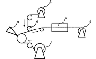
- 3 to 6 show an example of a schematic configuration diagram of a continuous casting coating apparatus for producing a composite polymer electrolyte membrane. It can be appropriately selected depending on the coating solution or porous film used for producing the composite electrolyte.
- FIG. 3 is a schematic configuration diagram in the case where a coating liquid is applied to a substrate, a porous film is bonded to the coated surface, and the substrate is continuously dried. Moreover, this structure can also apply a coating liquid to a porous film by bonding a base material and a porous film reversely, and can also bond a base material to a coating surface.
- the drying furnace in this case can prevent surface defects of the composite polymer electrolyte membrane by being conveyed in a floating manner.
- FIG. 4 is a schematic configuration diagram in the case where the coating liquid is applied to the base material, the porous film is divided into two in the thickness direction, one is bonded to the coating surface, and the other is wound up and reused.
- This is a particularly preferable embodiment when a porous film of 10 ⁇ m or less is used.
- the configuration diagram is shown as being divided into two sheets, but it is also possible to peel the opposite side of the peeled surface before bonding.
- FIG. 5 is a schematic configuration diagram in the case where the porous film is divided into two in the thickness direction, the coating liquid is applied on one side, and the substrates are bonded together. The other porous film is wound up and reused separately as in FIG.
- FIG. 6 is the same configuration as FIG. 4, but is a schematic configuration diagram in the case where the coating liquid is further applied on the porous film after drying in the first drying furnace and dried in the second drying furnace. Since the coating liquid can be impregnated from both sides, a composite polymer electrolyte membrane with little impregnation unevenness can be produced. Further, this configuration is described only in FIG. 6 for convenience, but can also be adopted in FIGS. Further, the position of the second coating part (3B) may be before the first drying furnace (4A). If the wettability between the porous film and the coating liquid is poor, such as when the coating liquid repels on the porous film, the configuration of FIG. 6 tends to improve the wettability between the porous film and the coating liquid. It is preferable from the viewpoint of the surface quality of the composite polymer electrolyte membrane.
- the porous film may be provided with mechanisms such as corona treatment, plasma treatment, static electricity removal, and chemical treatment.
- Ionic acid group density The following procedure is repeated 5 times, and the average value of three points excluding the maximum and minimum values is defined as the ionic acid group density (mmol / g).
- the produced electrolyte membrane was cut into 5 cm ⁇ 5 cm, dried under reduced pressure at 80 ° C. for 12 hours or more with a vacuum dryer, and the weight (Wm) was measured accurately (four digits after the decimal point).
- About 30 ml of about 0.2 wt% KCl aqueous solution was prepared in a sample bottle with a lid, and the weight (Wk) and K ion concentration (C 1 ) of the KCl aqueous solution were measured.
- the K ion concentration was measured with a capillary electrophoresis apparatus “CAPI-3300” manufactured by Otsuka Electronics. The measurement conditions are as follows.
- Electrophoresis Otsuka Electronics Cation Analysis
- Electrophoresis 5 ( ⁇ -CFI105)
- Measurement voltage 20kV (3)
- the electrolyte membrane was immersed in an aqueous KCl solution having a known weight and K ion concentration for 2 hours.
- the K ion concentration (C 2 ) of the aqueous KCl solution was measured again with a capillary electrophoresis apparatus. From the measured value, the sulfonic acid group density was calculated according to the following formula.
- Sulfonic acid group density (mmol / g) [ ⁇ Wk ⁇ (C 1 -C 2 ) ⁇ 1000 ⁇ / 39] / Wm (2) Measurement of salinity contained in membrane-like substance In this invention, salinity concentration is made into the density
- a film-like material before being brought into contact with water and / or an acidic aqueous solution was cut into 5 cm ⁇ 5 cm, dried under vacuum for 5 hours, and then weight W 0 was measured.
- the film was heat-treated at 300 ° C. for 10 minutes in a nitrogen atmosphere.
- C 3 (%) Ww ⁇ X / W 0 ⁇ 100
- C 4 (%) Ww ⁇ Y / W 0 ⁇ 100 (3)
- Measurement of residual solvent concentration of film-like substance The residual solvent concentration is the weight of the film-like substance before contact with water and / or acidic aqueous solution W1, and the same film-like substance is washed with warm water at 60 ° C. for 8 hours. Further, when the weight after vacuum drying at 100 ° C. for 8 hours is set to W2, it is calculated by the following formula.
- the weight average molecular weight of the polymer was measured by GPC.
- Tosoh's HLC-8022GPC is used as an integrated UV detector and differential refractometer, and two Tosoh TSK gel Super HM-Hs (inner diameter 6.0 mm, length 15 cm) are used as GPC columns.
- Viscosity measurement The viscosity at a temperature of 25 ° C. was measured using a rotary viscometer (rheometer RC20 manufactured by Rheotech Co., Ltd.) at a shear rate of 100 (s ⁇ 1 ). The geometry was taken from the RHEO2000 software using a cone and plate (attachment to fill the sample). C25-1 (2.5 cm ⁇ ) was used as the cone, and when measurement was difficult (less than 10 poise), it was changed to C50-1 (5.0 cm ⁇ ).
- the sample was allowed to stand for 2 hours in a constant temperature bath at a temperature of 23 ° C. and a humidity of 45%, and was quickly sandwiched between two slide glasses, and the distance between marked lines (L 1 ) was measured with a caliper. Further, after immersing the sample in hot water at 80 ° C. for 2 hours, the sample was quickly sandwiched between two glass slides, the distance between the marked lines (L 2 ) was measured with calipers, and the dimensional change rate was calculated according to the following formula.
- Gurley air permeability of porous membrane film Measured at 23 ° C. and 65% RH in accordance with JIS P-8117 (unit: second / 100 ml). The same measurement was performed five times for the same sample, and the average value of the obtained Gurley air permeability was defined as the Gurley air permeability of the sample.
- Porosity (%) 100 ⁇ 100 (W / ⁇ ) / (L2 ⁇ D) ⁇ in the above formula indicates the film density before stretching.
- ⁇ a value obtained by the density gradient method of D method of JIS K7112 (1980) 30 is used. At this time, ethanol and water were used as the density gradient liquid.
- This membrane electrode assembly was set in a JARI standard cell “Ex-1” (electrode area 25 cm 2 ) manufactured by Eiwa Co., Ltd., cell temperature: 80 ° C., hydrogen as fuel gas on one electrode, and nitrogen on the other electrode Gas was supplied, and the test was performed under humidification conditions: hydrogen gas 90% RH and nitrogen gas: 90% RH.
- the voltage was kept at OCV until it became 0.2 V or less, and the voltage was swept from 0.2 to 0.7 V at 1 mV / sec to examine the change in the current value. In this example, measurement was performed before and after the following start / stop test, and the value at 0.6 V was examined. When the membrane breaks, the amount of hydrogen permeation increases and the permeation current increases.
- this evaluation was carried out using a Solartron electrochemical measurement system (Solartron 1480 Electrochemical Interface and Solartron 1255B Frequency Response Analyzer).
- Montmorillonite clay K10 150 g and 99 g of dihydroxybenzophenone were reacted at 110 ° C. while distilling the produced by-products in 242 mL of ethylene glycol / 99 mL of trimethyl orthoformate. After 18 hours, 66 g of trimethyl orthoformate was added and reacted for 48 hours of synthesis. To the reaction solution was added 300 mL of ethyl acetate, and after filtration, extraction was performed 4 times with a 2% aqueous sodium hydrogen carbonate solution. Further, after concentration, the desired 2,2-bis (4-hydroxyphenyl) -1,3-dioxolane was obtained by recrystallization from dichloroethane.
- the obtained polymer had a stoichiometric value of ionic group density of 2.22 mmol / g and a weight average molecular weight of 210,000.
- NMP was added so that the viscosity of the polymerization stock solution was 0.5 Pa ⁇ s to obtain a polymerization stock solution A.
- the obtained polymer had a stoichiometric value of ionic group density of 2.28 mmol / g and a weight average molecular weight of 210,000.
- N-methyl-2-pyrrolidone was added so that the viscosity of the polymerization stock solution was 0.5 Pa ⁇ s to obtain a polymerization stock solution B.
- the obtained polymer had a stoichiometric value of ionic group density of 2.49 mmol / g and a weight average molecular weight of 320,000.
- NMP was added so that the viscosity of the polymerization stock solution was 0.5 Pa ⁇ s to obtain a polymerization stock solution C.
- polymerization stock solution F a polymerization stock solution was obtained by a stoichiometric value of ionic group density of 3.08 mmol / g and a weight average molecular weight of 200,000.
- NMP was added so that the viscosity of the polymerization stock solution was 0.5 Pa ⁇ s to obtain a polymerization stock solution F.
- Example 1 The polymerization stock solution A was directly centrifuged with an inverter / compact high-speed cooling centrifuge manufactured by Kubota Seisakusho (model No. 6930 with angle rotor RA-800 set, 25 ° C., 30 minutes, centrifugal force 20000 G). Since the precipitated solid (cake) and the supernatant (coating solution) could be separated cleanly, the supernatant was recovered and transferred to a separable flask while being filtered under pressure with a 10 ⁇ m polytetrafluoroethylene (PTFE) filter. Next, the solution is distilled under reduced pressure at 80 ° C. with stirring, NMP is removed until the viscosity of the supernatant liquid becomes 2 Pa ⁇ s, and further filtered under pressure with a 5 ⁇ m polytetrafluoroethylene (PTFE) filter. Got.
- an inverter / compact high-speed cooling centrifuge manufactured by Kubota Seisakusho (model No. 6930 with angle rot
- the coating speed was such that the solvent could be dried for 10 minutes at a solvent evaporation process temperature of 140 ° C.
- the coating conditions were adjusted so that the thickness of the electrolyte membrane after solvent evaporation was 20 ⁇ m, and the film was wound into a roll.
- the membrane was immersed in pure water at 25 ° C. for 10 minutes without peeling from the PET, and then immersed in 10% by weight sulfuric acid at 60 ° C. for 30 minutes to perform proton exchange of ionic groups.
- this membrane-like material was washed with pure water until the cleaning solution became neutral, and dried at 60 ° C. for 30 minutes to obtain an electrolyte membrane A having a thickness of 15 ⁇ m.
- Example 2 A coating solution B was obtained by directly centrifuging in the same manner as in Example 1 except that the polymerization stock solution B was used instead of the polymerization stock solution A and the centrifugal force was changed to 5000G.
- the coating speed was such that the solvent could be dried at a solvent evaporation process temperature of 160 ° C. for 15 minutes, and the coating conditions were adjusted so that the thickness of the electrolyte membrane after solvent evaporation was 20 ⁇ m, and the film was wound into a roll.
- a part of the roll was cut out and the film-like material was peeled off from the substrate. At this time, there was no problem in peelability, and no curling, wrinkles or surface defects occurred. A part of the film-like material at this time was sampled and the residual solvent concentration was measured and found to be 10% by weight. The salinity C 3 is 4.9% salt had sufficiently removed.
- the membrane was immersed in pure water at 25 ° C. for 10 minutes without peeling from the PET, and then immersed in 10% by weight sulfuric acid at 60 ° C. for 30 minutes to perform proton exchange of ionic groups.
- this membrane was washed with pure water until the cleaning solution became neutral, and dried at 60 ° C. for 30 minutes to obtain an electrolyte membrane B having a thickness of 18 ⁇ m.
- this electrolyte membrane B When this electrolyte membrane B was used to perform a fatigue test, it showed 2480000 times, the stress at break (78 MPa) and the elongation at break (210%), and had excellent mechanical properties without the influence of residual salt. It was.
- a film-like material having a film thickness of 20 ⁇ m was obtained as the coating liquid A ′ coating liquid in the same manner as in Example 1. Salinity C 3 at this time removal is salinity at 6.8% was insufficient.
- the membrane was immersed in pure water at 25 ° C. for 10 minutes without peeling from the PET, and then immersed in 10% by weight sulfuric acid at 60 ° C. for 30 minutes to perform proton exchange of ionic groups.
- this film-like material was washed with pure water until the washing solution became neutral, and dried at 60 ° C. for 30 minutes to obtain an electrolyte membrane A ′ having a film thickness of 15 ⁇ m.
- Example 3 Using an ultra-high-speed centrifuge VHF1001 manufactured by Kansai Centrifugal Co., Ltd., the polymerization stock solution C was directly supplied at a speed of 100 g / min, and continuous centrifugation was performed at a centrifugal force of 18000 G. The permeate was recovered, transferred to a separable flask and distilled under reduced pressure at 120 ° C. with stirring, and NMP was removed until the viscosity of the supernatant liquid reached 12 Pa ⁇ s. This solution was subjected to pressure filtration with a 3 ⁇ m polytetrafluoroethylene (PTFE) filter to obtain a coating solution C.
- PTFE polytetrafluoroethylene
- the coating speed was such that the solvent could be dried at a solvent evaporation process temperature of 150 ° C. for 15 minutes, and the coating conditions were adjusted so that the thickness of the electrolyte membrane after evaporation of the solvent was 20 ⁇ m.
- a part of the roll was cut out and the film-like material was peeled off from the substrate. At this time, there was no problem in peelability, and no curling, wrinkles or surface defects occurred. A part of the film-like material at this time was collected and the residual solvent concentration was measured and found to be 12% by weight. Furthermore, salinity C 3 salinity was 3.4% had sufficiently removed.
- the film-like material was not peeled off from PET and immersed in 10% by weight sulfuric acid at 60 ° C. for 30 minutes to hydrolyze the hydrolyzable soluble group and to exchange protons of the ionic group.
- this membrane-like material was washed with pure water until the washing solution became neutral, and dried at 60 ° C. for 30 minutes to obtain an electrolyte membrane C having a film thickness of 15 ⁇ m.
- a fatigue test using this electrolyte membrane C showed 2800000 times, had a stress at break 75 (MPa) and an elongation at break 205 (%), and had excellent mechanical properties without the influence of residual salt.
- the full width at half maximum of the peak at 133 ppm which is an index of the structural regularity of the electrolyte membrane C, was 580 Hz, indicating a high structural regularity.
- Example 4 Using an ultrahigh-speed centrifuge VHF1001 manufactured by Kansai Centrifugal Co., Ltd., the polymerization stock solution C was directly supplied at a speed of 100 g / min, and continuously centrifuged at a centrifugal force of 15000 G. The permeate was collected, transferred to a separable flask, 100 g of 18-crown-6 (Wako Pure Chemicals Reagent) was added as a cyclic metal scavenger, and distilled under reduced pressure at 120 ° C. with stirring. The viscosity of the supernatant liquid was 12 Pa ⁇ s. NMP was removed until. This solution was pressure filtered through a 3 ⁇ m polytetrafluoroethylene (PTFE) filter to obtain a coating solution C ′.
- PTFE polytetrafluoroethylene
- the coating speed was such that the solvent could be dried for 10 minutes at a solvent evaporation process temperature of 140 ° C.
- the coating conditions were adjusted so that the thickness of the electrolyte membrane after solvent evaporation was 23 ⁇ m, and the film was wound into a roll.
- a part of the roll was cut out and the film-like material was peeled off from the substrate. At this time, there was no problem in peelability, and no curling, wrinkles or surface defects occurred. A part of the film-like material at this time was collected and the residual solvent concentration was measured and found to be 25% by weight. Furthermore, salinity C 3 is 3.8% salt was sufficiently removed.
- the film-like material was not peeled off from PET and immersed in 10% by weight sulfuric acid at 60 ° C. for 30 minutes to hydrolyze the hydrolyzable soluble group and to exchange protons of the ionic group.
- a fatigue test using this electrolyte membrane C ′ showed 3700000 times, the stress at break 80 (MPa), the elongation at break 265 (%), and there was no influence of residual salt and excellent mechanical properties. Had. Further, in the solid 13 C-NMR spectrum, the full width at half maximum of the 133 ppm peak serving as an index of the structural regularity of the electrolyte membrane C ′ was 545 Hz, which was a high structural regularity.
- the coating speed was such that the solvent could be dried at a solvent evaporation process temperature of 150 ° C. for 15 minutes, and the coating conditions were adjusted so that the thickness of the electrolyte membrane after evaporation of the solvent was 20 ⁇ m.
- the dried film is peeled off from PET, immersed in pure water at 25 ° C. for 10 minutes to wash remaining NMP, etc., and then immersed in 10% by weight sulfuric acid at 60 ° C. for 30 minutes to hydrolyze hydrolyzable soluble groups. And proton exchange of ionic groups.
- the membrane was washed with pure water until the washing solution became neutral, and dried at 60 ° C. for 30 minutes to obtain an electrolyte membrane C ′′ having a thickness of 17 ⁇ m.
- the electrolyte membrane C ′′ was thin and clouded as a whole. When immersed in water, it became markedly cloudy and translucent.
- the half-width of the peak at 133 ppm for judging the structural regularity of the film was 780 Hz.
- Example 5 Using an ultra-high-speed centrifuge VHF1001 manufactured by Kansai Centrifugal Co., Ltd., the polymerization stock solution D was directly supplied at a speed of 100 g / min, and continuously centrifuged at a centrifugal force of 20000 G. The permeate was collected, transferred to a separable flask and distilled under reduced pressure at 120 ° C. with stirring, and NMP was removed until the viscosity of the supernatant liquid reached 5 Pa ⁇ s. This solution was pressure filtered through a 3 ⁇ m polytetrafluoroethylene (PTFE) filter to obtain a coating solution D.
- PTFE polytetrafluoroethylene
- the coating speed was such that the solvent could be dried at a solvent evaporation step temperature of 150 ° C. for 15 minutes, and the coating conditions were adjusted so that the thickness of the electrolyte membrane after evaporation of the solvent was 18 ⁇ m.
- a part of the roll was cut out and the film-like material was peeled off from the substrate. At this time, there was no problem in peelability, and no curling, wrinkles or surface defects occurred. A part of the film-like material at this time was collected and the residual solvent concentration was measured and found to be 25% by weight. Furthermore, salinity C 3 is 1.0% salt was sufficiently removed.
- the film-like material was not peeled off from PET and immersed in 10% by weight sulfuric acid at 60 ° C. for 30 minutes to hydrolyze the hydrolyzable soluble group and to exchange protons of the ionic group.
- the electrolyte membrane D has a thickness of 15 ⁇ m.
- a fatigue test using this electrolyte membrane D showed 3900000 times, the stress at break 69 (MPa) and the elongation at break 320 (%), and there was no influence of residual salt and excellent mechanical properties.
- the full width at half maximum of the 133 ppm peak serving as an index of the structural regularity of the electrolyte membrane D was 550 Hz, and the structural regularity was high.
- Example 6 A coating solution E was obtained in the same manner as in Example 5 except that the polymerization stock solution D of Example 5 was changed to the polymerization stock solution E. Using the coating liquid E, a film-like material was produced with a continuous casting coating apparatus for producing a composite polymer electrolyte membrane, which is schematically shown in FIG. A 125 ⁇ m PET film (“Lumirror (registered trademark)” manufactured by Toray Industries, Inc.) was used as a substrate, and a porous film was a biaxially oriented polypropylene film having a porosity of 70%, a Gurley permeability of 200 seconds / 100 ml, and a thickness of 20 ⁇ m. .
- Limirror registered trademark
- the casting application part 3 employs a slit die method, the application speed is such that it can be dried at a solvent evaporation process temperature of 100 ° C. for 15 minutes, and the coating conditions are adjusted so that the film thickness after solvent evaporation is 22 ⁇ m. And rolled into a roll. A part of the roll was cut out and the film-like material was peeled off from the substrate. At this time, there was no problem in peelability, and no curling, wrinkles or surface defects occurred. A part of the film-like material at this time was collected and the residual solvent concentration was measured and found to be 29% by weight. Furthermore, salinity C 3 is 1.0% salt had sufficiently removed.
- the film-like material was not peeled off from PET, and was immersed in 10% by weight sulfuric acid at 40 ° C. for 30 minutes to carry out hydrolysis of hydrolyzable soluble groups and proton exchange of ionic groups.
- the dimensional change was measured and found to be 2.0%. Further, in the solid 13 C-NMR spectrum, the full width at half maximum of the peak at 133 ppm, which is an index of the structural regularity of the polymer electrolyte in the composite polymer electrolyte membrane A, was 590 Hz, which was a high structural regularity.
- the output of the fuel cell using the composite polymer electrolyte membrane A under low humidification is 580 mW / cm 2 , and the hydrogen permeation current before and after the power generation durability evaluation test was measured. After evaluated at / cm 2 was good is durability 0.40MA / cm 2.
- Example 7 Using the coating liquid E of Example 6, a film-like material was produced with a continuous casting coating apparatus for producing a composite polymer electrolyte membrane, which is schematically shown in FIG.
- a 125 ⁇ m PET film (“Lumirror (registered trademark)” manufactured by Toray Industries, Inc.) is used as the base material, and the porous film is composed of two biaxially oriented polypropylene films having a porosity of 60%, a Gurley permeability of 250 seconds / 100 ml, and a thickness of 25 ⁇ m.
- the Gurley permeability was 50 sec / 100 ml and the thickness was 5 ⁇ m.
- the cast coating portions 3A and 3B are cast by a slit die, and the coating speed is such that the drying portion 4A can be dried at 100 ° C. and the drying portion 4B can be dried at 130 ° C. for 15 minutes.
- the coating conditions were adjusted so that the thickness was 13 ⁇ m, and the product was wound into a roll. A part of the roll was cut out and the film-like material was peeled off from the substrate. At this time, there was no problem in peelability, and no curling, wrinkles or surface defects occurred. A part of the film-like material at this time was sampled and the residual solvent concentration was measured and found to be 15% by weight. Furthermore, salinity C 3 were able to sufficiently remove and salinity 0.8%.
- the film-like material was not peeled off from PET, and was immersed in 10% by weight sulfuric acid at 40 ° C. for 30 minutes to carry out hydrolysis of hydrolyzable soluble groups and proton exchange of ionic groups.
- the dimensional change was measured and found to be 2.5%. Further, in the solid 13 C-NMR spectrum, the full width at half maximum of the 133 ppm peak serving as an index of the structural regularity of the polymer electrolyte in the composite polymer electrolyte membrane B was 580 Hz, which was a high structural regularity. Further, the output of the fuel cell using the composite polymer electrolyte membrane B under low humidification is 610 mW / cm 2. When the hydrogen permeation current before and after the test was measured by conducting the power generation durability evaluation, after evaluated at 0.55 mA / cm 2 was good is durable at 0.58mA / cm 2.
- Example 4 A composite polymer electrolyte membrane C was prepared in the same manner as in Example 6 except that the porous film of Example 6 was a biaxially oriented polypropylene film having a porosity of 50%, a Gurley air permeability of 500 seconds / 100 ml, and a thickness of 20 ⁇ m. Obtained.
- the ionic group density of this composite polymer electrolyte membrane C was 1.23 mmol / g.
- the output of the fuel cell using the composite polymer electrolyte membrane C under low humidification was 40 mW / cm 2 , and the output was clearly inferior to that of Example 6.
- Example 8 An ultrahigh-speed centrifuge VHF1001 manufactured by Kansai Centrifugal Co., Ltd. was used, the polymerization stock solution F was directly supplied at a speed of 100 g / min, and continuous centrifugation was performed at a centrifugal force of 8000 G. This separated liquid was directly filtered under pressure with a 100 ⁇ m polytetrafluoroethylene (PTFE) filter, and the permeate was transferred to a separable flask and distilled under reduced pressure at 120 ° C. with stirring. The viscosity of the supernatant liquid was 5 Pa ⁇ s. NMP was removed until the coating solution F was obtained.
- PTFE polytetrafluoroethylene
- the coating speed was such that the solvent could be dried at a solvent evaporation process temperature of 130 ° C. for 10 minutes.
- the coating conditions were adjusted so that the thickness of the electrolyte membrane after solvent evaporation was 25 ⁇ m, and the film was wound into a roll.
- a part of the roll was cut out and the film-like material was peeled off from the substrate. At this time, there was no problem in peelability, and no curling, wrinkles or surface defects occurred. A part of the film-like material at this time was sampled and the residual solvent concentration was measured and found to be 42% by weight. Furthermore, salinity C 3 salinity was 4.0% was sufficiently removed.
- the film-like material was peeled off from PET and immersed in 10% by weight sulfuric acid at 60 ° C. for 30 minutes to carry out hydrolysis of hydrolyzable soluble groups and proton exchange of ionic groups.
- An anode catalyst coating solution comprising “Nafion” (registered trademark) solution and n-propanol was applied and dried to prepare an anode catalyst layer.
- the anode catalyst coating solution was applied to the surface coated with the carbon black dispersion.
- a cathode catalyst coating solution composed of a Pt-supported carbon catalyst TEC10V50E manufactured by Tanaka Kikinzoku Kogyo Co., Ltd. and a “Nafion” (registered trademark) solution is applied to the electrode base material, and dried.
- a cathode catalyst layer was produced.
- MEA Membrane Electrode Assembly
- the composite polymer electrolyte membrane A of Example 6 was used as an electrolyte membrane, and was held between the anode and the cathode produced in the step (1), and 100 ° C.
- a membrane-electrode assembly (MEA) having an electrode area of 5 cm 2 was produced by heating and pressing at a temperature of 30 minutes.
- the MEA was sandwiched between separators, a 3% methanol (MeOH) aqueous solution was supplied to the anode side at 0.2 ml / min, and air was allowed to flow at 50 ml / min to the cathode side to evaluate power generation.
- MeOH 3% methanol
- Substrate extruding part 2 Porous film extruding part 3: Casting application part 3A: Casting application part 3B: Casting application part 4: Drying part 4A: Drying part 4B: Drying part 5: Combined high Molecular electrolyte membrane winding portion 6: Bonding portion 7: Porous film winding portion 8: Portion of porous film divided into two in the film thickness direction
- the electrolyte membrane and composite polymer electrolyte membrane obtained by the production method of the present invention can be applied to various electrochemical devices (for example, a fuel cell, a water electrolysis device, a chloroalkali electrolysis device, etc.).
- electrochemical devices for example, a fuel cell, a water electrolysis device, a chloroalkali electrolysis device, etc.
- it is suitable for a fuel cell, particularly suitable for a fuel cell using hydrogen or a methanol aqueous solution as a fuel, a mobile phone, a personal computer, a PDA, a video camera (camcorder), a digital camera, a handy terminal, an RFID reader.
- Digital audio players, portable devices such as various displays, electric appliances such as electric shavers and vacuum cleaners, electric tools, household power supply machines, cars such as passenger cars, buses and trucks, motorcycles, forklifts, electric assist bicycles, electric It is preferably used as a power supply source for a cart, an electric wheelchair, a moving body such as a ship and a railway, various robots, and a cyborg.
- portable devices it is used not only for power supply sources, but also for charging secondary batteries installed in portable devices, and also suitable as a hybrid power supply source used in combination with secondary batteries, capacitors, and solar cells.
Abstract
Description
(1) 試料をミルにより粉砕し、粒径を揃えるため、50メッシュの網ふるいにかけ、ふるいを通過したものを測定試料とする。
(2)サンプル管(蓋付き)を精密天秤で秤量する。
(3)前記(1)の試料 約0.1gをサンプル管に入れ、40℃で16時間、真空乾燥する。
(4) 試料入りのサンプル管を秤量し、試料の乾燥重量を求める。
(5)塩化ナトリウムを30重量%メタノール水溶液に溶かし、飽和食塩溶液を調製する。
(6)試料に前記(5)の飽和食塩溶液を25mL加え、24時間撹拌してイオン交換する。
(7) 生じた塩酸を0.02mol/L水酸化ナトリウム水溶液で滴定する。指示薬として市販の滴定用フェノールフタレイン溶液(0.1体積%)を2滴加え、薄い赤紫色になった点を終点とする。
(8)スルホン酸基密度は下記の式により求める。
スルホン酸基密度(mmol/g)=
〔水酸化ナトリウム水溶液の濃度(mmol/ml)×滴下量(ml)〕/試料の乾燥重量(g)
本発明のイオン性基を有する電解質には本発明の目的を阻害しない範囲において、他の成分、例えば導電性若しくはイオン伝導性を有さない不活性なポリマーや有機あるいは無機の化合物が含有されていても構わない。 For reference, the procedure for measurement by neutralization titration is shown. The measurement shall be performed three times or more and the average shall be taken.
(1) A sample is pulverized by a mill, and in order to make the particle diameter uniform, the sample is passed through a 50-mesh screen sieve and the sample passed through the sieve is used as a measurement sample.
(2) Weigh the sample tube (with lid) with a precision balance.
(3) About 0.1 g of the sample of (1) is put in a sample tube and vacuum dried at 40 ° C. for 16 hours.
(4) Weigh the sample tube with the sample and determine the dry weight of the sample.
(5) Dissolve sodium chloride in a 30 wt% aqueous methanol solution to prepare a saturated saline solution.
(6) Add 25 mL of the saturated salt solution of (5) above to the sample, and stir for 24 hours for ion exchange.
(7) Titrate the resulting hydrochloric acid with 0.02 mol / L aqueous sodium hydroxide solution. Two drops of a commercially available titration phenolphthalein solution (0.1% by volume) as an indicator are added, and the point at which light reddish purple is obtained is the end point.
(8) The sulfonic acid group density is determined by the following formula.
Sulfonic acid group density (mmol / g) =
[Concentration of sodium hydroxide aqueous solution (mmol / ml) × Drip amount (ml)] / Dry weight of sample (g)
The electrolyte having an ionic group of the present invention contains other components, for example, an inactive polymer or an organic or inorganic compound having no conductivity or ionic conductivity, as long as the object of the present invention is not impaired. It doesn't matter.


また、本発明では便宜上、溶媒以外の成分、例えば吸湿した水分や、水で抽出される成分および揮発性添加剤は残存溶媒として取り扱う。 Residual solvent concentration in film (wt%) = (W1-W2) / W1 × 100 (Formula 1)
In the present invention, for the sake of convenience, components other than the solvent, for example, moisture absorbed, components extracted with water, and volatile additives are handled as residual solvents.
空隙率=100-100(W/ρ)/(L2 ×D)
上記式中のρは、延伸前のフィルム密度を示す。ρはJIS K7112(1980)のD法の密度勾配菅法にて求めた値を用いる。この時の密度勾配菅用液は、エタノールと水を用いる。 The porosity of the porous film can be determined from the following equation by cutting the porous film into a square and measuring the length L (cm), weight W (g), and thickness D (cm) of one side.
Porosity = 100-100 (W / ρ) / (L2 × D)
Ρ in the above formula indicates the film density before stretching. ρ uses a value obtained by the density gradient method of D method of JIS K7112 (1980). At this time, ethanol and water are used as the density gradient liquid.
下記手順を5回行い、最大値と最小値を除いた3点の平均値をイオン酸基密度(mmol/g)とする。
(1)作製した電解質膜を5cm×5cmに切り取り真空乾燥機にて80℃12時間以上減圧乾燥後、重量(Wm)を正確(小数点下4桁)に測定した。
(2)蓋付きのサンプル瓶に約0.2wt%のKCl水溶液約30ml準備し、KCl水溶液の重量(Wk)とKイオン濃度(C1)を測定した。Kイオン濃度は大塚電子製キャピラリー電気泳動装置”CAPI-3300”で測定した。測定条件は下記の通りである。 (1) Ionic acid group density The following procedure is repeated 5 times, and the average value of three points excluding the maximum and minimum values is defined as the ionic acid group density (mmol / g).
(1) The produced electrolyte membrane was cut into 5 cm × 5 cm, dried under reduced pressure at 80 ° C. for 12 hours or more with a vacuum dryer, and the weight (Wm) was measured accurately (four digits after the decimal point).
(2) About 30 ml of about 0.2 wt% KCl aqueous solution was prepared in a sample bottle with a lid, and the weight (Wk) and K ion concentration (C 1 ) of the KCl aqueous solution were measured. The K ion concentration was measured with a capillary electrophoresis apparatus “CAPI-3300” manufactured by Otsuka Electronics. The measurement conditions are as follows.
泳動液:大塚電子製 陽イオン分析用泳動液5(α-CFI105)
測定電圧:20kV
(3)重量とKイオン濃度既知のKCl水溶液に上記電解質膜を2時間浸漬した。
(4)該KCl水溶液のKイオン濃度(C2)を再度キャピラリー電気泳動装置で測定した。測定した値から、下記式に従いスルホン酸基密度を算出した。
スルホン酸基密度(mmol/g)=〔{Wk×(C1-C2)×1000}/39〕/Wm
(2)膜状物に含まれる塩分の測定
本発明では、塩分濃度を、便宜上、膜状物中に存在するカチオンの濃度とする。
(1)水および/または酸性水溶液と接触させる前の膜状物を5cm×5cmに切り取り、5時間真空乾燥後、重量W0を測定した。
(2)次ぎに該膜状物を窒素雰囲気下で300℃、10分間熱処理した。
(3)次ぎ蓋付きのサンプル瓶に水を約150ml準備し、水の重量Wwを測定し、前記膜状物を浸漬し、40℃に加熱して1時間浸漬した。
(4)試験後の水中のカチオン濃度を大塚電子製キャピラリー電気泳動装置”CAPI-3300”で測定し、合計した値をX%とした。測定条件は下記の通りである。 Measurement method: Drop method (25mm)
Electrophoresis: Otsuka Electronics Cation Analysis Electrophoresis 5 (α-CFI105)
Measurement voltage: 20kV
(3) The electrolyte membrane was immersed in an aqueous KCl solution having a known weight and K ion concentration for 2 hours.
(4) The K ion concentration (C 2 ) of the aqueous KCl solution was measured again with a capillary electrophoresis apparatus. From the measured value, the sulfonic acid group density was calculated according to the following formula.
Sulfonic acid group density (mmol / g) = [{Wk × (C 1 -C 2 ) × 1000} / 39] / Wm
(2) Measurement of salinity contained in membrane-like substance In this invention, salinity concentration is made into the density | concentration of the cation which exists in a membrane-like substance for convenience.
(1) A film-like material before being brought into contact with water and / or an acidic aqueous solution was cut into 5 cm × 5 cm, dried under vacuum for 5 hours, and then weight W 0 was measured.
(2) Next, the film was heat-treated at 300 ° C. for 10 minutes in a nitrogen atmosphere.
(3) About 150 ml of water was prepared in a sample bottle with a next lid, the weight Ww of the water was measured, the film was immersed, heated to 40 ° C. and immersed for 1 hour.
(4) The cation concentration in the water after the test was measured with a capillary electrophoresis apparatus “CAPI-3300” manufactured by Otsuka Electronics Co., Ltd., and the total value was X%. The measurement conditions are as follows.
泳動液:大塚電子製 陽イオン分析用泳動液5(α-CFI105)
測定電圧:20kV
(5)次ぎに水および/または酸性水溶液と接触させる工程後の膜状物についても同様にカチオン濃度を測定し、合計した値をY%とした。
(6)以下の計算式で膜中の塩分(カチオン)濃度C3、C4を算出した。 Measurement method: Drop method (25mm)
Electrophoresis: Otsuka Electronics Cation Analysis Electrophoresis 5 (α-CFI105)
Measurement voltage: 20kV
(5) Next, the cation concentration was measured in the same manner for the membrane after the step of contacting with water and / or an acidic aqueous solution, and the total value was defined as Y%.
(6) The salinity (cation) concentrations C 3 and C 4 in the membrane were calculated by the following formula.
C4(%)=Ww×Y/W0×100
(3)膜状物の残存溶媒濃度の測定
残存溶媒濃度は水および/または酸性水溶液に接触させる前の膜状物の重量をW1、同じ膜状物を60℃の温水中で8時間水洗し、さらに100℃で8時間真空乾燥後の重量をW2とした時に下式で計算して求める。 C 3 (%) = Ww × X / W 0 × 100
C 4 (%) = Ww × Y / W 0 × 100
(3) Measurement of residual solvent concentration of film-like substance The residual solvent concentration is the weight of the film-like substance before contact with water and / or acidic aqueous solution W1, and the same film-like substance is washed with warm water at 60 ° C. for 8 hours. Further, when the weight after vacuum drying at 100 ° C. for 8 hours is set to W2, it is calculated by the following formula.
(4)重量平均分子量
ポリマーの重量平均分子量をGPCにより測定した。紫外検出器と示差屈折計の一体型装置として東ソー製HLC-8022GPCを、またGPCカラムとして東ソー製TSK gel SuperHM-H(内径6.0mm、長さ15cm)2本を用い、N-メチル-2-ピロリドン溶媒(臭化リチウムを10mmol/L含有するN-メチル-2-ピロリドン溶媒)にて、流量0.2mL/minで測定し、標準ポリスチレン換算により重量平均分子量を求めた。 Residual solvent concentration in film (weight%) = (W1-W2) / W1 × 100
(4) Weight average molecular weight The weight average molecular weight of the polymer was measured by GPC. Tosoh's HLC-8022GPC is used as an integrated UV detector and differential refractometer, and two Tosoh TSK gel Super HM-Hs (inner diameter 6.0 mm, length 15 cm) are used as GPC columns. -Measured with a pyrrolidone solvent (N-methyl-2-pyrrolidone solvent containing 10 mmol / L of lithium bromide) at a flow rate of 0.2 mL / min, and the weight average molecular weight was determined in terms of standard polystyrene.
ミツトヨ製グラナイトコンパレータスタンドBSG-20にセットしたミツトヨ製ID-C112型を用いて測定した。 (5) Film thickness The film thickness was measured using Mitutoyo ID-C112 type set on Mitutoyo granite comparator stand BSG-20.
回転型粘度計(レオテック社製レオメータRC20型)を用いて剪断速度100(s-1)の条件で温度25℃の粘度を測定した。ジオメトリーは(試料を充填するアタッチメント)コーン&プレートを使用して、RHEO2000ソフトウェアで得られた値を採用した。コーンはC25-1(2.5cmφ)を使用し、測定困難な場合は(10poise未満)C50-1(5.0cmφ)に変更した。 (6) Viscosity measurement The viscosity at a temperature of 25 ° C. was measured using a rotary viscometer (rheometer RC20 manufactured by Rheotech Co., Ltd.) at a shear rate of 100 (s −1 ). The geometry was taken from the RHEO2000 software using a cone and plate (attachment to fill the sample). C25-1 (2.5 cmφ) was used as the cone, and when measurement was difficult (less than 10 poise), it was changed to C50-1 (5.0 cmφ).
電解質膜をJISのK-7127に準じ、2号型試験片の1/2サイズにカットしたものを試験片とした。測定装置には島津製“オートグラフ”を用い、試験速度は20±2.0mm/minで実施し、破断点応力(MPa)および破断点伸度(%)を測定した。 (7) Tensile test In accordance with JIS K-7127, the electrolyte membrane was cut into ½ size of No. 2 type test piece to obtain a test piece. “Autograph” manufactured by Shimadzu was used as the measuring apparatus, the test speed was 20 ± 2.0 mm / min, and the stress at break (MPa) and the elongation at break (%) were measured.
島津製作所社製 電磁力式微少試験機“MMT-101N”を使用し、下記条件で電解質膜が破断するまでのサイクル数を調べた。
試験雰囲気;25℃ 50%RH
試験片幅;5mm
波形種別;正弦波
最大応力;20MPa
最小応力; 2MPa
周波数 ;100Hz
(9)電解質膜の構造規則性測定
固体13C DD/MAS NMRにより電解質膜の構造規則を測定した。試料は5mm幅に裁断し、ジルコニア製固体NMR試料管に充填して測定した。測定条件は下記する。
芳香族のメインピークである133ppmのピークの半値全幅(Hz)で判断し、この値が小さい(ピークがシャープ)程、構造規則性が高いと判断した。
1)装置:Chemagnetics社製CMX-300
Bruker社製AVANCE400
2)測定:DD/MAS法 緩和時間モード
3)測定角:13C
4)観測周波数:75.497791MHz、100.6248425MHz
5)パルス幅:4.2μs、3.3μs
6)観測幅:30.03kHz、40.00kHz
7)ポイント数:観測ポイント1024、データポイント8192
8)パルス繰り返し時間:PD:150s、10s
9)化学シフト基準:シリコーンゴム(内部基準1.56ppm)
10)試料回転数:9kHz、14kHz
11)測定温度:室温
(10)寸法変化率(面方向)
電解質膜を6cm×1cmの短冊状に切り出し、長尺側の両端から約5mmのところに標線を記入した(標線間距離5cm)。前記サンプルを温度23℃、湿度45%の恒温槽に2h放置後、素早く2枚のスライドガラスに挟み込み標線間距離(L1)をノギスで測定した。さらに、同サンプルを80℃の熱水に2h浸漬後、素早く2枚のスライドガラスに挟み込み標線間距離(L2)をノギスで測定し下記式に従い寸法変化率を算出した。 (8) Fatigue test of electrolyte membrane Using an electromagnetic force micro tester “MMT-101N” manufactured by Shimadzu Corporation, the number of cycles until the electrolyte membrane breaks was examined under the following conditions.
Test atmosphere: 25 ° C 50% RH
Specimen width: 5 mm
Waveform type; sine wave maximum stress; 20 MPa
Minimum stress: 2 MPa
Frequency: 100Hz
(9) Structure regularity measurement of electrolyte membrane The structure regularity of the electrolyte membrane was measured by solid 13 C DD / MAS NMR. The sample was cut into a width of 5 mm, filled in a zirconia solid NMR sample tube and measured. The measurement conditions are as follows.
Judgment was made based on the full width at half maximum (Hz) of the peak at 133 ppm, which is the aromatic main peak, and the smaller this value (the sharper the peak), the higher the structural regularity.
1) Equipment: CMX-300 manufactured by Chemagnetics
Bruker AVANCE400
2) Measurement: DD / MAS method Relaxation time mode 3) Measurement angle: 13 C
4) Observation frequency: 75.497791 MHz, 10.0.6248425 MHz
5) Pulse width: 4.2 μs, 3.3 μs
6) Observation width: 30.03 kHz, 40.00 kHz
7) Number of points: observation point 1024, data point 8192
8) Pulse repetition time: PD: 150 s, 10 s
9) Chemical shift standard: Silicone rubber (internal standard 1.56ppm)
10) Sample rotation speed: 9 kHz, 14 kHz
11) Measurement temperature: Room temperature (10) Dimensional change rate (surface direction)
The electrolyte membrane was cut into a 6 cm × 1 cm strip, and a marked line was written about 5 mm from both ends on the long side (distance between marked lines was 5 cm). The sample was allowed to stand for 2 hours in a constant temperature bath at a temperature of 23 ° C. and a humidity of 45%, and was quickly sandwiched between two slide glasses, and the distance between marked lines (L 1 ) was measured with a caliper. Further, after immersing the sample in hot water at 80 ° C. for 2 hours, the sample was quickly sandwiched between two glass slides, the distance between the marked lines (L 2 ) was measured with calipers, and the dimensional change rate was calculated according to the following formula.
(11)多孔質膜フィルムのガーレ透気度
JIS P-8117に準拠して、23℃、65%RHにて測定した(単位:秒/100ml)。同じサンプルについて同様の測定を5回行い、得られたガーレ透気度の平均値を当該サンプルのガーレ透気度とした。 Dimensional change rate (%) = (L 2 −L 1 ) / L 1 × 100
(11) Gurley air permeability of porous membrane film Measured at 23 ° C. and 65% RH in accordance with JIS P-8117 (unit: second / 100 ml). The same measurement was performed five times for the same sample, and the average value of the obtained Gurley air permeability was defined as the Gurley air permeability of the sample.
二軸配向フィルムを正方形に切り取り、一辺の長さL(cm)、重量W(g)、厚みD(cm)、を測定して、以下の式より求めた。 (12) Porosity of porous membrane film A biaxially oriented film is cut into a square, and the length L (cm), weight W (g), and thickness D (cm) of one side are measured. It was.
上記式中のρは、延伸前のフィルム密度を示す。ρはJIS K7112(1980) 30のD法の密度勾配菅法にて求めた値を用いる。この時の密度勾配菅用液は、エタノールと水を用いた。 Porosity (%) = 100−100 (W / ρ) / (L2 × D)
Ρ in the above formula indicates the film density before stretching. As ρ, a value obtained by the density gradient method of D method of JIS K7112 (1980) 30 is used. At this time, ethanol and water were used as the density gradient liquid.
A.水素透過電流の測定
市販の電極、BASF社製燃料電池用ガス拡散電極“ELAT(登録商標)LT120ENSI”5g/m2Ptを5cm角にカットしたものを1対準備し、燃料極、酸化極として電解質膜を挟むように対向して重ね合わせ、150℃、5MPaで3分間加熱プレスを行い、評価用膜電極複合体を得た。 (13) Power generation evaluation Measurement of hydrogen permeation current A pair of commercially available electrodes, gas diffusion electrode for fuel cell “ELAT (registered trademark) LT120ENSI” 5 g / m 2 Pt cut into 5 cm square by BASF, was prepared as a fuel electrode and an oxidation electrode. The two membranes were placed facing each other so as to sandwich the electrolyte membrane, and heated and pressed at 150 ° C. and 5 MPa for 3 minutes to obtain a membrane electrode assembly for evaluation.
上記セルを使用し、セル温度:80℃、燃料ガス:水素、酸化ガス:空気、ガス利用率:水素70%/酸素40%、加湿条件:水素ガス60%RH、空気:50%RHの条件で試験を行った。条件としては、OCVで1分間保持し、1A/cm2の電流密度で2分間発電し、最後に水素ガスおよび空気の供給を停止して2分間発電を停止し、これを1サイクルとして繰り返す耐久性試験を実施した。耐久性試験前と3000サイクル後に上記水素透過電流の測定を実施しその差を調べた。また、この試験の負荷変動は菊水電子工業社製の電子負荷装置“PLZ664WA”を使用して行った。 B. Durability test Using the above cell, cell temperature: 80 ° C., fuel gas: hydrogen, oxidizing gas: air, gas utilization: hydrogen 70% / oxygen 40%, humidification conditions: hydrogen gas 60% RH, air: 50% The test was performed under the condition of RH. The conditions are: hold for 1 minute at OCV, generate electricity for 2 minutes at a current density of 1 A / cm 2 , finally stop supplying hydrogen gas and air for 2 minutes, and repeat this as one cycle A sex test was performed. The hydrogen permeation current was measured before and after 3000 cycles and the difference was examined. In addition, the load fluctuation in this test was performed using an electronic load device “PLZ664WA” manufactured by Kikusui Electronics Corporation.
上記燃料電池セルをセル温度80℃、燃料ガス:水素、酸化ガス:空気、ガス利用率:水素70%/酸素40%、加湿条件;アノード側30%RH/カソード30%RH、背圧0.1MPa(両極)において電流-電圧(I-V)測定した。電流-電圧曲線の電流と電圧の積が最高になる点を電極面積で割った値を出力密度とした。 C. Evaluation of power generation under low humidification The above fuel cell has a cell temperature of 80 ° C., fuel gas: hydrogen, oxidizing gas: air, gas utilization: hydrogen 70% / oxygen 40%, humidification conditions; anode side 30% RH / cathode 30 Current-voltage (IV) measurement was performed at% RH and a back pressure of 0.1 MPa (both electrodes). The value obtained by dividing the point at which the product of the current and voltage in the current-voltage curve is highest divided by the electrode area was taken as the output density.
ジソジウム 3,3’-ジスルホネート-4,4’-ジフルオロベンゾフェノン(G2)の合成 (Synthesis Example 1; monomer having an ionic group)
Synthesis of disodium 3,3'-disulfonate-4,4'-difluorobenzophenone (G2)

(合成例2;加水分解性可溶性付与基を有するモノマー)
2,2-ビス(4-ヒドロキシフェニル)-1,3-ジオキソラン(G1)の合成 109.1 g (Aldrich reagent) of 4,4′-difluorobenzophenone was reacted at 150 ° C. for 10 hours in 150 mL of fuming sulfuric acid (50% SO 3) (Wako Pure Chemicals reagent). Thereafter, the mixture was poured little by little into a large amount of water, neutralized with NaOH, and 200 g of sodium chloride was added to precipitate the composite. The resulting precipitate was filtered off and recrystallized with an aqueous ethanol solution to obtain disodium 3,3′-disulfonate-4,4′-difluorobenzophenone.
(Synthesis Example 2: Monomer having hydrolyzable solubility-imparting group)
Synthesis of 2,2-bis (4-hydroxyphenyl) -1,3-dioxolane (G1)

撹拌機、窒素導入管、Dean-Starkトラップを備えた6Lの反応容器に、炭酸カリウム235g(アルドリッチ試薬、1.7mol)、4,4’-ジヒドロキシテトラフェニルメタン352g(1.0mol)4,4’-ジフルオロベンゾフェノン65g(アルドリッチ試薬0.3mol)、およびイオン性基を含有するモノマーであるジソジウム 3,3’-ジスルホネート-4,4’-ジフルオロベンゾフェノン296g(0.7mol)を入れ、窒素置換後、N-メチル-2-ピロリドン(NMP)3800g、トルエン550gを加え、環流しながら160℃で脱水後、昇温してトルエン除去し、200℃で1時間脱塩重縮合を行った。得られたポリマーのイオン性基密度の量論値は2.22mmol/gで、重量平均分子量は21万であった。次に重合原液の粘度が0.5Pa・sになるようにNMPを添加し重合原液Aを得た。 Reference Example 1 Production Example of Polymer Electrolyte Polymer Stock Solution A having an Ionic Group Density of 2 mmol / g or More
In a 6 L reaction vessel equipped with a stirrer, nitrogen introduction tube, and Dean-Stark trap, 235 g of potassium carbonate (Aldrich reagent, 1.7 mol), 352 g of 4,4′-dihydroxytetraphenylmethane (1.0 mol) 4,4 Put 65 g of '-difluorobenzophenone (Aldrich reagent 0.3 mol) and 296 g (0.7 mol) of disodium 3,3'-disulfonate-4,4'-difluorobenzophenone, a monomer containing an ionic group, and replace with nitrogen Thereafter, 3800 g of N-methyl-2-pyrrolidone (NMP) and 550 g of toluene were added, dehydrated at 160 ° C. while refluxing, heated to remove toluene, and subjected to desalting polycondensation at 200 ° C. for 1 hour. The obtained polymer had a stoichiometric value of ionic group density of 2.22 mmol / g and a weight average molecular weight of 210,000. Next, NMP was added so that the viscosity of the polymerization stock solution was 0.5 Pa · s to obtain a polymerization stock solution A.
撹拌機、窒素221g(アルドリッチ試薬、1.6mol)、4,4’-ジヒドロキシジフェニルスルホン(ビスフェノールS)252g(東京化成試薬1.0mol)4,4’-ジフルオロベンゾフェノン87g(アルドリッチ試薬0.4mol)、およびイオン性基を含有するモノマーであるジソジウム 3,3’-ジスルホネート-4,4’-ジフルオロベンゾフェノン253g(0.6mol)を入れ、窒素置換後、N-メチル-2-ピロリドン(NMP)3200g、トルエン450gを加え、環流しながら160℃で脱水後、昇温してトルエン除去し、200℃で1時間脱塩重縮合を行った。得られたポリマーのイオン性基密度の量論値は2.28mmol/gで、重量平均分子量は21万であった。次に重合原液の粘度が0.5Pa・sになるようにN-メチル-2-ピロリドンを添加し重合原液Bを得た。 Reference Example 2 Production Example of Polymer Electrolyte Polymer Stock Solution B with an Ionic Group Density of 2 mmol / g or More
Stirrer, 221 g of nitrogen (Aldrich reagent, 1.6 mol), 252 g of 4,4′-dihydroxydiphenylsulfone (bisphenol S) (1.0 mol of Tokyo Kasei Reagent), 87 g of 4,4′-difluorobenzophenone (0.4 mol of Aldrich reagent) , And 253 g (0.6 mol) of disodium 3,3′-disulfonate-4,4′-difluorobenzophenone which is a monomer containing an ionic group, and after nitrogen substitution, N-methyl-2-pyrrolidone (NMP) 3200 g and 450 g of toluene were added, dehydrated at 160 ° C. while refluxing, heated to remove toluene, and subjected to demineralization polycondensation at 200 ° C. for 1 hour. The obtained polymer had a stoichiometric value of ionic group density of 2.28 mmol / g and a weight average molecular weight of 210,000. Next, N-methyl-2-pyrrolidone was added so that the viscosity of the polymerization stock solution was 0.5 Pa · s to obtain a polymerization stock solution B.
撹拌機、窒素導入管、Dean-Starkトラップを備えた5Lの反応容器に、炭酸カリウム221g(アルドリッチ試薬、1.6mol)、4,4’-ビフェノール37g(アルドリッチ試薬0.5mol)、2,2-ビス(4-ヒドロキシフェニル)-1,3-ジオキソラン207g(0.8mol)、4,4’-ジフルオロベンゾフェノン87g(アルドリッチ試薬0.4mol)、およびイオン性基を含有するモノマーであるジソジウム 3,3’-ジスルホネート-4,4’-ジフルオロベンゾフェノン253g(0.6mol)を入れ、窒素置換後、N-メチル-2-ピロリドン(NMP)3200g、トルエン500gを加え、環流しながら160℃で脱水後、昇温してトルエン除去し、200℃で1時間脱塩重縮合を行った。得られたポリマーのイオン性基密度の量論値は2.49mmol/gで、重量平均分子量は32万であった。次に重合原液の粘度が0.5Pa・sになるようにNMPを添加し重合原液Cを得た。 Reference Example 3 Production Example of Polymer Stock Solution C for Polymer Electrolyte having an Ionic Group Density of 2 mmol / g or More and a Soluble Group-Granting Group
In a 5 L reaction vessel equipped with a stirrer, nitrogen introduction tube, and Dean-Stark trap, 221 g of potassium carbonate (Aldrich reagent, 1.6 mol), 37 g of 4,4′-biphenol (0.5 mol of Aldrich reagent), 2,2 Bis (4-hydroxyphenyl) -1,3-dioxolane 207 g (0.8 mol), 4,4′-difluorobenzophenone 87 g (Aldrich reagent 0.4 mol), and disodium 3, which is a monomer containing an ionic group Add 253 g (0.6 mol) of 3′-disulfonate-4,4′-difluorobenzophenone, replace with nitrogen, add 3200 g of N-methyl-2-pyrrolidone (NMP) and 500 g of toluene, and dehydrate at 160 ° C. while refluxing. Thereafter, the temperature was raised to remove toluene, and desalting polycondensation was performed at 200 ° C. for 1 hour. The obtained polymer had a stoichiometric value of ionic group density of 2.49 mmol / g and a weight average molecular weight of 320,000. Next, NMP was added so that the viscosity of the polymerization stock solution was 0.5 Pa · s to obtain a polymerization stock solution C.
撹拌機、窒素導入管、Dean-Starkトラップを備えた5Lの反応容器に、4,4’-ジヒドロキシベンゾフェノン43g(アルドリッチ試薬0.2mol)、2,2-ビス(4-ヒドロキシフェニル)-1,3-ジオキソラン207g(0.8mol)、4,4’-ジフルオロベンゾフェノン87g(アルドリッチ試薬0.2mol)、およびイオン性基を含有するモノマーであるジソジウム 3,3’-ジスルホネート-4,4’-ジフルオロベンゾフェノン338g(0.8mol)を入れ、窒素置換後、N-メチル-2-ピロリドン(NMP)2500g、トルエン500g、環状金属捕捉剤として18-クラウン-6 186g(和光純薬試薬)を加え、モノマーが全て溶解したことを確認後、炭酸カリウム248g(アルドリッチ試薬、1.8mol)を加え、環流しながら160℃で脱水後、昇温してトルエン除去し、200℃で1時間脱塩重縮合を行った。得られたポリマーのイオン性基密度の量論値は3.08mmol/gで、重量平均分子量は28万であった。次に重合原液の粘度が0.5Pa・sになるようにNMPを添加し重合原液Dを得た。 Reference Example 4 Production Example of Polymer Stock Solution D of Polymer Electrolyte having an Ionic Group Density of 2 mmol / g or More and a Soluble Group-Granting Group
In a 5 L reaction vessel equipped with a stirrer, nitrogen introduction tube and Dean-Stark trap, 43 g of 4,4′-dihydroxybenzophenone (Aldrich reagent 0.2 mol), 2,2-bis (4-hydroxyphenyl) -1, 207 g (0.8 mol) of 3-dioxolane, 87 g of 4,4′-difluorobenzophenone (0.2 mol of Aldrich reagent), and disodium 3,3′-disulfonate-4,4′- which is a monomer containing an ionic group After adding 338 g (0.8 mol) of difluorobenzophenone and substituting with nitrogen, 2500 g of N-methyl-2-pyrrolidone (NMP), 500 g of toluene, and 186 g of 18-crown-6 as a cyclic metal scavenger (Wako Pure Chemical Industries, Ltd.) were added. After confirming that all the monomers were dissolved, 248 g of potassium carbonate (Aldrich Drugs, 1.8 mol) and the mixture was dehydrated at 160 ° C. under reflux, heated and then toluene is removed and subjected to 1 hour desalting polycondensation 200 ° C.. The obtained polymer had a stoichiometric value of ionic group density of 3.08 mmol / g and a weight average molecular weight of 280,000. Next, NMP was added so that the viscosity of the polymerization stock solution was 0.5 Pa · s to obtain a polymerization stock solution D.
撹拌機、窒素導入管、Dean-Starkトラップを備えた5Lの反応容器に、4,4’-ジヒドロキシベンゾフェノン43g(アルドリッチ試薬0.2mol)、2,2-ビス(4-ヒドロキシフェニル)-1,3-ジオキソラン207g(0.8mol)、4,4’-ビフェノール93g(アルドリッチ試薬0.5mol)、およびイオン性基を含有するモノマーであるジソジウム 3,3’-ジスルホネート-4,4’-ジフルオロベンゾフェノン422g(1.0mol)を入れ、窒素置換後、N-メチル-2-ピロリドン(NMP)3000、トルエン450g、環状金属捕捉剤として18-クラウン-6 232g(和光純薬試薬)を加え、モノマーが全て溶解したことを確認後、炭酸カリウム276g(アルドリッチ試薬、2.0mol)を加え、環流しながら160℃で脱水後、昇温してトルエン除去し、190℃で1時間脱塩重縮合を行った。得られたポリマーのイオン性基密度の量論値は3.72mmol/gで、重量平均分子量は36万であった。次に重合原液の粘度が0.5Pa・sになるようにNMPを添加し重合原液Eを得た。 (Reference Example 5: Production example of polymerization stock solution E of polymer electrolyte having ionic group density of 2 mmol / g or more and having soluble group imparting group)
In a 5 L reaction vessel equipped with a stirrer, nitrogen introduction tube and Dean-Stark trap, 43 g of 4,4′-dihydroxybenzophenone (Aldrich reagent 0.2 mol), 2,2-bis (4-hydroxyphenyl) -1, 207 g (0.8 mol) of 3-dioxolane, 93 g of 4,4′-biphenol (0.5 mol of Aldrich reagent), and disodium 3,3′-disulfonate-4,4′-difluoro which is a monomer containing an ionic group 422 g (1.0 mol) of benzophenone was added, and after nitrogen substitution, N-methyl-2-pyrrolidone (NMP) 3000, 450 g of toluene, and 232 g of 18-crown-6 as a cyclic metal scavenger (Wako Pure Chemical Reagent) were added. 276 g of potassium carbonate (Aldrich reagent, 2.0 m l) and the mixture was dehydrated at 160 ° C. under reflux, heated and then toluene is removed and subjected to 1 hour desalting polycondensation 190 ° C.. The obtained polymer had a stoichiometric value of ionic group density of 3.72 mmol / g and a weight average molecular weight of 360,000. Next, NMP was added so that the viscosity of the polymerization stock solution was 0.5 Pa · s to obtain a polymerization stock solution E.
撹拌機、窒素導入管、Dean-Starkトラップを備えた5Lの反応容器に、4,4’-ジヒドロキシベンゾフェノン43g(アルドリッチ試薬0.2mol)、2,2-ビス(4-ヒドロキシフェニル)-1,3-ジオキソラン207g(0.8mol)、4,4’-ジフルオロベンゾフェノン87g(アルドリッチ試薬0.2mol)、およびイオン性基を含有するモノマーであるジソジウム 3,3’-ジスルホネート-4,4’-ジフルオロベンゾフェノン338g(0.8mol)を入れ、窒素置換後、N-メチル-2-ピロリドン(NMP)2500g、トルエン500g、グリコール類としてエチレングリコール100gと分子量400のポリエチレングリコール50g、炭酸カリウム248g(アルドリッチ試薬、1.8mol)を加え、環流しながら160℃で脱水後、昇温してトルエン除去し、200℃で1時間脱塩重縮合を行った。得られたポリマーのイオン性基密度の量論値は3.08mmol/gで、重量平均分子量は20万であった。次に重合原液の粘度が0.5Pa・sになるようにNMPを添加し重合原液Fを得た。 (Reference Example 6: Production Example of Polymer Stock Solution F of Polymer Electrolyte having an Ionic Group Density of 2 mmol / g or More and a Soluble Group-Granting Group)
In a 5 L reaction vessel equipped with a stirrer, a nitrogen introduction tube, and a Dean-Stark trap, 43 g of 4,4′-dihydroxybenzophenone (Aldrich reagent 0.2 mol), 2,2-bis (4-hydroxyphenyl) -1, 207 g (0.8 mol) of 3-dioxolane, 87 g of 4,4′-difluorobenzophenone (0.2 mol of Aldrich reagent), and disodium 3,3′-disulfonate-4,4′- which is a monomer containing an ionic group 338 g (0.8 mol) of difluorobenzophenone was added, and after nitrogen substitution, 2500 g of N-methyl-2-pyrrolidone (NMP), 500 g of toluene, 100 g of ethylene glycol as glycols, 50 g of polyethylene glycol having a molecular weight of 400, 248 g of potassium carbonate (Aldrich reagent) 1.8mo ) And the mixture was dehydrated at 160 ° C. under reflux, heated and then toluene is removed and subjected to 1 hour desalting polycondensation 200 ° C.. The obtained polymer had a stoichiometric value of ionic group density of 3.08 mmol / g and a weight average molecular weight of 200,000. Next, NMP was added so that the viscosity of the polymerization stock solution was 0.5 Pa · s to obtain a polymerization stock solution F.
久保田製作所製インバーター・コンパクト高速冷却遠心機(型番6930にアングルローターRA-800をセット、25℃、30分間、遠心力20000G)で重合原液Aの直接遠心分離を行った。沈降固形物(ケーキ)と上澄み液(塗液)がきれいに分離できたので上澄み液を回収し、10μmのポリテトラフルオロエチレン(PTFE)製フィルターで加圧濾過しながらセパラブルフラスコに移した。次に、撹拌しながら80℃で減圧蒸留し、上澄み液の粘度が2Pa・sになるまでNMPを除去し、さらに5μmのポリテトラフルオロエチレン(PTFE)製フィルターで加圧濾過して塗液Aを得た。 Example 1
The polymerization stock solution A was directly centrifuged with an inverter / compact high-speed cooling centrifuge manufactured by Kubota Seisakusho (model No. 6930 with angle rotor RA-800 set, 25 ° C., 30 minutes, centrifugal force 20000 G). Since the precipitated solid (cake) and the supernatant (coating solution) could be separated cleanly, the supernatant was recovered and transferred to a separable flask while being filtered under pressure with a 10 μm polytetrafluoroethylene (PTFE) filter. Next, the solution is distilled under reduced pressure at 80 ° C. with stirring, NMP is removed until the viscosity of the supernatant liquid becomes 2 Pa · s, and further filtered under pressure with a 5 μm polytetrafluoroethylene (PTFE) filter. Got.
重合原液Aの代わりに重合原液Bを使用し遠心力を5000Gとした以外は実施例1と同様に直接遠心分離を実施し塗液Bを得た。 (Example 2)
A coating solution B was obtained by directly centrifuging in the same manner as in Example 1 except that the polymerization stock solution B was used instead of the polymerization stock solution A and the centrifugal force was changed to 5000G.
重合原液Aを1週間静置し遠心分離工程をおこなわないで上澄みを回収しセパラブルフラスコに移した。次に、撹拌しながら80℃で減圧蒸留し、せずそのまま上澄みの粘度が2Pa・sになるまでNMPを除去し、さらに5μmのポリテトラフルオロエチレン(PTFE)製フィルターで加圧濾過して塗液A’を得た。 (Comparative Example 1)
The polymerization stock solution A was allowed to stand for 1 week, and the supernatant was collected without performing a centrifugation step and transferred to a separable flask. Next, the solution was distilled under reduced pressure at 80 ° C. with stirring, and NMP was removed as it was until the supernatant had a viscosity of 2 Pa · s, and further filtered under pressure with a 5 μm polytetrafluoroethylene (PTFE) filter. Liquid A ′ was obtained.
関西遠心分離社製超高速遠心分離機VHF1001型を使用し、重合原液Cを100g/分の速度で直接供給し、18000Gの遠心力で連続的に遠心分離を行った。透過液を回収し、セパラブルフラスコに移して撹拌しながら120℃で減圧蒸留し、上澄み液の粘度が12Pa・sになるまでNMPを除去した。この液を3μmのポリテトラフルオロエチレン(PTFE)製フィルターで加圧濾過し塗液Cを得た。 (Example 3)
Using an ultra-high-speed centrifuge VHF1001 manufactured by Kansai Centrifugal Co., Ltd., the polymerization stock solution C was directly supplied at a speed of 100 g / min, and continuous centrifugation was performed at a centrifugal force of 18000 G. The permeate was recovered, transferred to a separable flask and distilled under reduced pressure at 120 ° C. with stirring, and NMP was removed until the viscosity of the supernatant liquid reached 12 Pa · s. This solution was subjected to pressure filtration with a 3 μm polytetrafluoroethylene (PTFE) filter to obtain a coating solution C.
関西遠心分離社製超高速遠心分離機VHF1001型を使用し、重合原液Cを100g/分の速度で直接供給し、15000Gの遠心力で連続的に遠心分離を行った。透過液を回収し、セパラブルフラスコに移し、環状金属捕捉剤として18-クラウン-6 100g(和光純薬試薬)を加え、撹拌しながら120℃で減圧蒸留し、上澄み液の粘度が12Pa・sになるまでNMPを除去した。この液を3μmのポリテトラフルオロエチレン(PTFE)製フィルターで加圧濾過し塗液C’を得た。 Example 4
Using an ultrahigh-speed centrifuge VHF1001 manufactured by Kansai Centrifugal Co., Ltd., the polymerization stock solution C was directly supplied at a speed of 100 g / min, and continuously centrifuged at a centrifugal force of 15000 G. The permeate was collected, transferred to a separable flask, 100 g of 18-crown-6 (Wako Pure Chemicals Reagent) was added as a cyclic metal scavenger, and distilled under reduced pressure at 120 ° C. with stirring. The viscosity of the supernatant liquid was 12 Pa · s. NMP was removed until. This solution was pressure filtered through a 3 μm polytetrafluoroethylene (PTFE) filter to obtain a coating solution C ′.
重合原液Cを大過剰の水に徐々に添加し沈殿精製を行った。この際、析出した高分子電解質の膨潤が大きく、十分な塩分の洗浄ができず、また、作業性が著しくに悪かった。沈殿ポリマーを濾布で濾過して水切り後、80℃で12時間減圧乾燥を行なった。該ポリマーをNMPに再溶解した後、粘度が12Pa・sの塗液とした後、3μmのポリテトラフルオロエチレン(PTFE)製フィルターで加圧濾過を実施したが、溶媒不溶のゲル分により、濾過が困難であったため、10μmのフィルターに変更し加圧濾過を行い塗液C”を得た。 (Comparative Example 2)
The polymerization stock solution C was gradually added to a large excess of water for precipitation purification. At this time, the deposited polymer electrolyte was greatly swollen, and sufficient salt content could not be washed, and the workability was extremely poor. The precipitated polymer was filtered through a filter cloth, drained, and dried under reduced pressure at 80 ° C. for 12 hours. After the polymer was redissolved in NMP, the coating solution was made to have a viscosity of 12 Pa · s, and then filtered under pressure using a 3 μm polytetrafluoroethylene (PTFE) filter. Therefore, the filter was changed to a 10 μm filter and subjected to pressure filtration to obtain a coating liquid C ″.
塗布速度は溶媒蒸発工程温度150℃で15分間乾燥できる速度とし、溶媒蒸発後の電解質膜の厚みが20μmとなるように塗工条件を調整しロール状に巻き取った。 A 125 μm PET film (“Lumirror (registered trademark)” manufactured by Toray Industries, Inc.) was used as a base material, and coating solution C ″ was continuously cast by a coater (coater part; slit die coater) capable of continuous coating. Also, the vertical streaks were likely to enter due to the foreign matter caused by the gel.
The coating speed was such that the solvent could be dried at a solvent evaporation process temperature of 150 ° C. for 15 minutes, and the coating conditions were adjusted so that the thickness of the electrolyte membrane after evaporation of the solvent was 20 μm.
った。 When this electrolyte membrane C ″ was used to conduct a fatigue test, it was 50000 times under the influence of the gelled product and was inferior to Examples 3 and 4 in which centrifugation was performed. ), The elongation at break was 19 (%), and the mechanical properties were lowered due to the influence of the residual salt.
It was.
関西遠心分離社製超高速遠心分離機VHF1001型を使用し、重合原液Dを100g/分の速度で直接供給し、20000Gの遠心力で連続的に遠心分離を行った。透過液を回収し、セパラブルフラスコに移して撹拌しながら120℃で減圧蒸留し、上澄み液の粘度が5Pa・sになるまでNMPを除去した。この液を3μmのポリテトラフルオロエチレン(PTFE)製フィルターで加圧濾過し塗液Dを得た。 (Example 5)
Using an ultra-high-speed centrifuge VHF1001 manufactured by Kansai Centrifugal Co., Ltd., the polymerization stock solution D was directly supplied at a speed of 100 g / min, and continuously centrifuged at a centrifugal force of 20000 G. The permeate was collected, transferred to a separable flask and distilled under reduced pressure at 120 ° C. with stirring, and NMP was removed until the viscosity of the supernatant liquid reached 5 Pa · s. This solution was pressure filtered through a 3 μm polytetrafluoroethylene (PTFE) filter to obtain a coating solution D.
重合原液Dを大過剰の水に徐々に添加し沈殿精製を行った。この際、析出ポリマーの膨潤が極めて大きく、ポリマーと水の分離ができなかった。一部のポリマー膨潤液をサンプリングして流延塗布し水を蒸発させること膜状物とした。しかし、塩分も除かれていないので膜は白濁し、塩分濃度C3は26.0%であった。 (Comparative Example 2)
The polymerization stock solution D was gradually added to a large excess of water for precipitation purification. At this time, swelling of the precipitated polymer was extremely large, and the polymer and water could not be separated. A part of the polymer swelling solution was sampled and cast and applied to evaporate water to obtain a film-like product. However, since it is not also removed salt film was opaque and salinity C 3 was 26.0%.
実施例5の重合原液Dを重合原液Eに変更した以外は実施例5と同様に実施し塗液Eを得た。塗液Eを使用し、図3に概略構成図示す複合化高分子電解質膜製造用の連続流延塗布装置で膜状物を作製した。基材として125μmのPETフィルム(東レ製“ルミラー(登録商標)”)を用い、多孔質フィルムは空隙率70%、ガーレ透気度200秒/100ml、厚み20μmの二軸配向ポリプロピレンフィルムを使用した。 (Example 6)
A coating solution E was obtained in the same manner as in Example 5 except that the polymerization stock solution D of Example 5 was changed to the polymerization stock solution E. Using the coating liquid E, a film-like material was produced with a continuous casting coating apparatus for producing a composite polymer electrolyte membrane, which is schematically shown in FIG. A 125 μm PET film (“Lumirror (registered trademark)” manufactured by Toray Industries, Inc.) was used as a substrate, and a porous film was a biaxially oriented polypropylene film having a porosity of 70%, a Gurley permeability of 200 seconds / 100 ml, and a thickness of 20 μm. .
実施例6の塗液Eを使用し、図6に概略構成図示す複合化高分子電解質膜製造用の連続流延塗布装置で膜状物を作製した。基材として125μmのPETフィルム(東レ製“ルミラー(登録商標)”)を用い、多孔質フィルムは空隙率60%、ガーレ透気度250秒/100ml、厚み25μmの二軸配向ポリプロピレンフィルムを二枚に割いてガーレ透気度50秒/100ml、厚み5μmとして使用した。 (Example 7)
Using the coating liquid E of Example 6, a film-like material was produced with a continuous casting coating apparatus for producing a composite polymer electrolyte membrane, which is schematically shown in FIG. A 125 μm PET film (“Lumirror (registered trademark)” manufactured by Toray Industries, Inc.) is used as the base material, and the porous film is composed of two biaxially oriented polypropylene films having a porosity of 60%, a Gurley permeability of 250 seconds / 100 ml, and a thickness of 25 μm. The Gurley permeability was 50 sec / 100 ml and the thickness was 5 μm.
重合原液Eを大過剰の水に徐々に添加し沈殿精製を行った。この際、高分子電解質のイオン交換容量が大きすぎ水に溶解し精製ができなかった。溶液をサンプリングして流延塗布し水を蒸発させることで膜状物とした。しかし、塩分も除かれていないので膜は白濁し、塩分濃度C3は32.0%であり、精製方法として実施例6、7の遠心分離法より劣っていた。 (Comparative Example 3)
The polymerization stock solution E was gradually added to a large excess of water for precipitation purification. At this time, the ion exchange capacity of the polymer electrolyte was too large to dissolve in water and purification could not be performed. The solution was sampled, cast and applied to evaporate water to form a film. However, since it is not also removed salt film was opaque and salinity C 3 is 32.0% was inferior centrifugation of Examples 6 and 7 as a purification method.
実施例6の多孔質フィルムを空隙率50%、ガーレ透気度500秒/100ml、厚み20μmの二軸配向ポリプロピレンフィルムを使用し以外は、実施例6と同様に複合化高分子電解質膜Cを得た。この複合化高分子電解質膜Cのイオン性基密度は1.23mmol/gであった。また、複合化高分子電解質膜Cを使用した燃料電池の低加湿下での出力は40mW/cm2であり出力が実施例6と比較して明らかに劣っていた。 (Comparative Example 4)
A composite polymer electrolyte membrane C was prepared in the same manner as in Example 6 except that the porous film of Example 6 was a biaxially oriented polypropylene film having a porosity of 50%, a Gurley air permeability of 500 seconds / 100 ml, and a thickness of 20 μm. Obtained. The ionic group density of this composite polymer electrolyte membrane C was 1.23 mmol / g. The output of the fuel cell using the composite polymer electrolyte membrane C under low humidification was 40 mW / cm 2 , and the output was clearly inferior to that of Example 6.
関西遠心分離社製超高速遠心分離機VHF1001型を使用し、重合原液Fを100g/分の速度で直接供給し、8000Gの遠心力で連続的に遠心分離を行った。この分離液を100μmのポリテトラフルオロエチレン(PTFE)製フィルターで直接加圧濾過し、透過液をセパラブルフラスコに移して撹拌しながら120℃で減圧蒸留し、上澄み液の粘度が5Pa・sになるまでNMPを除去し、塗液Fを得た。 (Example 8)
An ultrahigh-speed centrifuge VHF1001 manufactured by Kansai Centrifugal Co., Ltd. was used, the polymerization stock solution F was directly supplied at a speed of 100 g / min, and continuous centrifugation was performed at a centrifugal force of 8000 G. This separated liquid was directly filtered under pressure with a 100 μm polytetrafluoroethylene (PTFE) filter, and the permeate was transferred to a separable flask and distilled under reduced pressure at 120 ° C. with stirring. The viscosity of the supernatant liquid was 5 Pa · s. NMP was removed until the coating solution F was obtained.
(1)アノードとカソードの作製
炭素繊維の織物からなる米国イーテック(E-TEK)社製カーボンクロスに、20%PTFE処理を行った。具体的には、ポリテトラフルオロエチレン(以下PTFEと略す)を20重量%含む水分散液にカーボンクロスを浸漬、引き上げ後、乾燥、焼成した。その片面にPTFEを20重量%含むカーボンブラック分散液を塗工し、焼成して電極基材を作製した。この電極基材上に、ジョンソンマッセイ(Johson&Matthey)社製Pt-Ru担持カーボン触媒”HiSPEC”(登録商標)7000と”HiSPEC”(登録商標)6000、デュポン(DuPont)社製20%”ナフィオン”(”Nafion”)(登録商標)溶液とn-プロパノールからなるアノード触媒塗液を塗工し、乾燥してアノード触媒層を作製した。アノード触媒塗液の塗工はカーボンブラック分散液を塗工した面に行った。また、同様に、上記の電極基材上に、田中貴金属工業社製Pt担持カーボン触媒TEC10V50Eと”ナフィオン”(”Nafion”)(登録商標)溶液からなるカソード触媒塗液を塗工し、乾燥してカソード触媒層を作製した。 (Reference example 7: Application to direct methanol fuel cell (DMFC))
(1) Production of anode and cathode 20% PTFE treatment was performed on a carbon cloth made of carbon fiber fabric manufactured by E-TEK. Specifically, the carbon cloth was immersed in an aqueous dispersion containing 20% by weight of polytetrafluoroethylene (hereinafter abbreviated as PTFE), pulled up, dried, and fired. A carbon black dispersion containing 20% by weight of PTFE was applied on one side and baked to prepare an electrode substrate. On this electrode substrate, a Pt-Ru-supported carbon catalyst “HiSPEC” (registered trademark) 7000 and “HiSPEC” (registered trademark) 6000 manufactured by Johnson & Matthey, and 20% “Nafion” (produced by DuPont) ( An anode catalyst coating solution comprising “Nafion” (registered trademark) solution and n-propanol was applied and dried to prepare an anode catalyst layer. The anode catalyst coating solution was applied to the surface coated with the carbon black dispersion. Similarly, a cathode catalyst coating solution composed of a Pt-supported carbon catalyst TEC10V50E manufactured by Tanaka Kikinzoku Kogyo Co., Ltd. and a “Nafion” (registered trademark) solution is applied to the electrode base material, and dried. Thus, a cathode catalyst layer was produced.
実施例6の複合化高分子電解質膜Aを電解質膜として、それを前記工程(1)で作製したアノードとカソードで夾持し、100℃の温度で30分間加熱プレスして、電極面積が5cm2となる膜-電極複合体(MEA)を作製した。このMEAを、セパレータに挟み、アノード側に3%メタノール(MeOH)水溶液を0.2ml/minで供給し、カソード側に空気を50ml/minで流して、発電評価を実施した。その結果120mW/cm2の出力が得られ、DMFC用途としても高い性能を有していることがわかった。 (2) Production and Evaluation of Membrane Electrode Assembly (MEA) The composite polymer electrolyte membrane A of Example 6 was used as an electrolyte membrane, and was held between the anode and the cathode produced in the step (1), and 100 ° C. A membrane-electrode assembly (MEA) having an electrode area of 5 cm 2 was produced by heating and pressing at a temperature of 30 minutes. The MEA was sandwiched between separators, a 3% methanol (MeOH) aqueous solution was supplied to the anode side at 0.2 ml / min, and air was allowed to flow at 50 ml / min to the cathode side to evaluate power generation. As a result, an output of 120 mW / cm 2 was obtained, and it was found that it has high performance as a DMFC application.
2:多孔質フィルム捲き出し部分
3:流延塗布部分
3A:流延塗布部分
3B:流延塗布部分
4:乾燥部分
4A:乾燥部分
4B:乾燥部分
5:複合化高分子電解質膜巻き取り部分
6:貼り合わせ部分
7:多孔質フィルム捲き取り部部分
8:多孔質フィルムを膜厚方向の二枚に割く部分 1: Substrate extruding part 2: Porous film extruding part 3: Casting application part 3A:
Claims (13)
- イオン性基密度が2mmol/g以上の高分子電解質の重合溶液から、直接、遠心分離で、重縮合時に生成した塩分の一部を除去して塗液を得る工程、該塗液を基材上に流延塗布する工程、溶媒の一部を除去して基材上に膜状物を得る工程、該膜状物を水および/または酸性水溶液と接触させ重縮合時に生成した塩分を除去する工程を有する高分子電解質膜の製造方法 A step of removing a part of the salt generated during polycondensation directly from a polymer electrolyte polymerization solution having an ionic group density of 2 mmol / g or more by centrifugation to obtain a coating solution; The step of cast coating on the substrate, the step of removing a part of the solvent to obtain a film-like product on the substrate, the step of contacting the membrane-like product with water and / or an acidic aqueous solution and the removal of the salt produced during the polycondensation For producing polymer electrolyte membrane having
- 前記溶媒の一部を除去して基材上に得た膜状物に含まれる塩分濃度をC3重量%、該基材上の膜状物を水および/または酸性水溶液と接触させ重縮合時に生成した塩分を除去した後の塩分濃度をC4重量%としたとき、C3<5でかつ、C4/C3<0.3である請求項1記載の高分子電解質膜の製造方法 At the time of polycondensation, the salt concentration contained in the film-like material obtained by removing a part of the solvent is 3 % by weight of C, and the film-like material on the substrate is contacted with water and / or an acidic aqueous solution. 2. The method for producing a polymer electrolyte membrane according to claim 1, wherein C 3 <5 and C 4 / C 3 <0.3 when the salinity concentration after removing the produced salinity is C 4 wt%.
- 塗液を基材上に流延塗布する工程の前に、環状金属捕捉剤および/またはグリコール類を添加する工程を有し、かつ、溶媒の一部を除去して基材上に膜状物を得る工程の後に、環状金属捕捉剤および/またはグリコール類を除去する工程を有する請求項1記載の高分子電解質膜の製造方法 Before the step of casting the coating liquid onto the substrate, it has a step of adding a cyclic metal scavenger and / or glycols, and a part of the solvent is removed to form a film on the substrate. The method for producing a polymer electrolyte membrane according to claim 1, further comprising a step of removing the cyclic metal scavenger and / or glycols after the step of obtaining
- イオン性基の金属塩を含有するモノマーを環状金属捕捉剤および/またはグリコール類を添加して脱塩重縮合する工程をさらに有する請求項1記載の高分子電解質膜の製造方法 The method for producing a polymer electrolyte membrane according to claim 1, further comprising a step of subjecting a monomer containing a metal salt of an ionic group to demineralization polycondensation by adding a cyclic metal scavenger and / or glycols.
- 5重量%以上、50重量%以下の濃度の溶媒を残存させた状態で該基材上の膜状物を水および/または酸性水溶液と接触させ重縮合時に生成した塩分を除去する請求項1記載の高分子電解質膜の製造方法 The salt content generated during polycondensation is removed by contacting the film-like material on the substrate with water and / or an acidic aqueous solution in a state where a solvent having a concentration of 5 wt% or more and 50 wt% or less remains. Method for producing polymer electrolyte membrane of
- 基材から剥離することなく該基材上の膜状物を水および/または酸性水溶液と接触させ重縮合時に生成した塩分を除去する請求項1記載の高分子電解質膜の製造方法 The method for producing a polymer electrolyte membrane according to claim 1, wherein the film-like material on the substrate is brought into contact with water and / or an acidic aqueous solution to remove the salt generated during polycondensation without peeling from the substrate.
- 前記高分子電解質が加水分解性可溶性付与基を含有する芳香族炭化水素系電解質である請求項1記載の高分子電解質膜の製造方法。 The method for producing a polymer electrolyte membrane according to claim 1, wherein the polymer electrolyte is an aromatic hydrocarbon electrolyte containing a hydrolyzable solubility-imparting group.
- 前記環状金属捕捉剤が、クラウンエーテルである請求項3または4記載の高分子電解質膜の製造方法。 The method for producing a polymer electrolyte membrane according to claim 3 or 4, wherein the cyclic metal scavenger is a crown ether.
- 前記グリコール類が多価アルコール類または分子量500以下のポリエチレングリコールである請求項3または4記載の高分子電解質膜の製造方法。 The method for producing a polymer electrolyte membrane according to claim 3 or 4, wherein the glycol is a polyhydric alcohol or a polyethylene glycol having a molecular weight of 500 or less.
- 前記高分子電解質膜の固体13C DD/MAS NMRにより測定した133ppmのピークの半値幅が700Hz以下である請求項1記載の高分子電解質膜の製造方法。 2. The method for producing a polymer electrolyte membrane according to claim 1, wherein the full width at half maximum of a 133 ppm peak measured by solid-state 13 C DD / MAS NMR of the polymer electrolyte membrane is 700 Hz or less.
- 請求項1記載の高分子電解質膜の製造方法で製造された高分子電解質膜と、空隙率60%以上、ガーレ透気度が1000秒/100cc以下の多孔質フィルムを含有する複合化高分子電解質膜。 A composite polymer electrolyte comprising a polymer electrolyte membrane produced by the method for producing a polymer electrolyte membrane according to claim 1 and a porous film having a porosity of 60% or more and a Gurley air permeability of 1000 seconds / 100 cc or less. film.
- 多孔質フィルムが二軸配向多孔質ポリプロピレンフィルムである請求項11記載の複合化高分子電解質膜。 The composite polymer electrolyte membrane according to claim 11, wherein the porous film is a biaxially oriented porous polypropylene film.
- 80℃の熱水に24時間浸漬した際の面方向の寸法変化率が5%以下でかつイオン性基密度が1.5mmol/g以上である請求項11記載の複合化高分子電解質膜。 The composite polymer electrolyte membrane according to claim 11, wherein the dimensional change rate in the surface direction when immersed in hot water at 80 ° C for 24 hours is 5% or less and the ionic group density is 1.5 mmol / g or more.
Priority Applications (4)
| Application Number | Priority Date | Filing Date | Title |
|---|---|---|---|
| CN201080004701.2A CN102282709B (en) | 2009-01-19 | 2010-01-15 | Process for producing polymeric electrolyte membrane |
| EP10731292.8A EP2381522B1 (en) | 2009-01-19 | 2010-01-15 | Process for producing polymeric electrolyte membrane |
| KR1020117016713A KR101678706B1 (en) | 2009-01-19 | 2010-01-15 | Process for producing polymeric electrolyte membrane |
| US13/144,987 US9059448B2 (en) | 2009-01-19 | 2010-01-15 | Process for producing polymeric electrolyte membrane |
Applications Claiming Priority (6)
| Application Number | Priority Date | Filing Date | Title |
|---|---|---|---|
| JP2009008552A JP5407063B2 (en) | 2009-01-19 | 2009-01-19 | Method for producing polymer electrolyte membrane |
| JP2009-008552 | 2009-01-19 | ||
| JP2009010638A JP5407355B2 (en) | 2009-01-21 | 2009-01-21 | Manufacturing method of electrolyte membrane |
| JP2009-010638 | 2009-01-21 | ||
| JP2009-168542 | 2009-07-17 | ||
| JP2009168542 | 2009-07-17 |
Publications (1)
| Publication Number | Publication Date |
|---|---|
| WO2010082623A1 true WO2010082623A1 (en) | 2010-07-22 |
Family
ID=42339877
Family Applications (1)
| Application Number | Title | Priority Date | Filing Date |
|---|---|---|---|
| PCT/JP2010/050403 WO2010082623A1 (en) | 2009-01-19 | 2010-01-15 | Process for producing polymeric electrolyte membrane |
Country Status (6)
| Country | Link |
|---|---|
| US (1) | US9059448B2 (en) |
| EP (1) | EP2381522B1 (en) |
| KR (1) | KR101678706B1 (en) |
| CN (1) | CN102282709B (en) |
| TW (1) | TWI446618B (en) |
| WO (1) | WO2010082623A1 (en) |
Cited By (2)
| Publication number | Priority date | Publication date | Assignee | Title |
|---|---|---|---|---|
| JP2015176790A (en) * | 2014-03-17 | 2015-10-05 | トヨタ自動車株式会社 | Method and device for manufacturing reinforcement type electrolyte film |
| JP2016509493A (en) * | 2012-12-21 | 2016-03-31 | ヴォルカノ コーポレイションVolcano Corporation | Preparation and use of piezoelectric film for ultrasonic transducer |
Families Citing this family (15)
| Publication number | Priority date | Publication date | Assignee | Title |
|---|---|---|---|---|
| EP2873107B1 (en) * | 2012-07-10 | 2017-05-17 | Areva Stockage d'Energie | Fuel cell having improved electric insulation |
| JP6156358B2 (en) * | 2012-11-27 | 2017-07-05 | 東レ株式会社 | POLYMER ELECTROLYTE COMPOSITION, AND POLYMER ELECTROLYTE MEMBRANE, MEMBRANE ELECTRODE COMPOSITION AND SOLID POLYMER TYPE FUEL CELL USING SAME |
| CA2934381A1 (en) | 2013-12-19 | 2015-06-25 | Treofan Germany Gmbh & Co. Kg | Ion-exchange membrane made of a biaxially stretched .beta.-porous film |
| KR101965041B1 (en) | 2014-06-26 | 2019-04-02 | 고쿠리츠다이가쿠호징 나라 센탄카가쿠기쥬츠 다이가쿠인 다이가쿠 | Nanomaterial dopant composition composite, dopant composition, and method for manufacturing nanomaterial dopant composition composite |
| JP6636282B2 (en) * | 2015-08-17 | 2020-01-29 | Toyo Tire株式会社 | A method, apparatus, and program for calculating an interaction parameter between a polymer and a solvent. |
| JP6661401B2 (en) * | 2016-02-22 | 2020-03-11 | 株式会社Screenホールディングス | Manufacturing equipment for membrane / electrode assemblies |
| CN107887642B (en) * | 2016-09-30 | 2021-04-02 | 东丽先端材料研究开发(中国)有限公司 | Polymer electrolyte membrane and method for producing same |
| KR102001470B1 (en) * | 2016-10-12 | 2019-10-01 | 한국과학기술연구원 | Composite polymer electrolyte membrane for fuel cell, and method of manufacturing the same |
| CN115197583B (en) * | 2017-02-10 | 2024-03-15 | 三菱化学株式会社 | Conductive composition, method for producing conductive composition, and method for producing conductive body |
| CN108630972B (en) * | 2018-03-14 | 2021-08-06 | 上海博暄能源科技有限公司 | Preparation method of antioxidant graphene quantum dot modified proton exchange membrane |
| WO2019230219A1 (en) * | 2018-05-31 | 2019-12-05 | 株式会社クレハ | Adhesive composition, separator structure, electrode structure, non-aqueous electrolyte secondary battery, and manufacturing method therefor |
| CN110071327A (en) * | 2019-04-10 | 2019-07-30 | 深圳新宙邦科技股份有限公司 | A kind of solid electrolyte and polymer Li-ion battery |
| CN110229325B (en) * | 2019-06-10 | 2022-04-19 | 宜宾天原集团股份有限公司 | Post-treatment method of bisphenol A type poly (arylene ether nitrile) |
| CN110283310A (en) * | 2019-06-10 | 2019-09-27 | 宜宾天原集团股份有限公司 | A kind of preparation method of light color poly (arylene ether nitrile) |
| DK180599B1 (en) * | 2020-01-20 | 2021-10-14 | Blue World Technologies Holding ApS | Apparatus and process for making acid-doped proton exchange membranes |
Citations (13)
| Publication number | Priority date | Publication date | Assignee | Title |
|---|---|---|---|---|
| JPH01299979A (en) | 1988-05-27 | 1989-12-04 | Motohiro Gotanda | Door latch lock locking and unlocking device |
| JPH0693114A (en) | 1992-06-13 | 1994-04-05 | Hoechst Ag | Polyelectrolyte film and its preparation |
| US20020091225A1 (en) | 2000-09-20 | 2002-07-11 | Mcgrath James E. | Ion-conducting sulfonated polymeric materials |
| JP2004528683A (en) | 2001-03-21 | 2004-09-16 | ビクトレックス マニュファクチャリング リミテッド | Fuel cell |
| JP2005158724A (en) * | 2003-11-05 | 2005-06-16 | Toray Ind Inc | Polymer electrolyte membrane |
| JP2005171230A (en) | 2003-11-05 | 2005-06-30 | Toray Ind Inc | Biaxially oriented microporous film and method for producing the same |
| JP2006253124A (en) * | 2005-02-09 | 2006-09-21 | Toray Ind Inc | Electrolyte film support, method for treating polymer electrolyte composite film using the same, polymer electrolyte composite film having treated thereby, and fuel cell using same |
| JP2006261103A (en) | 2005-02-15 | 2006-09-28 | Toray Ind Inc | Polymer electrolyte material; and polymer electrolyte component, membrane-electrode assembly and polymer electrolyte fuel cell using it |
| WO2007046226A1 (en) | 2005-10-18 | 2007-04-26 | Toray Industries, Inc. | Microporous film for power storage device separator and power storage device separator making use of the same |
| JP2007204578A (en) * | 2006-02-01 | 2007-08-16 | Toray Ind Inc | Polymer electrolyte material, polymer electrolyte membrane, and polymer electrolyte part, polymer electrolyte membrane, membrane electrode assembly and polymer electrolyte-type fuel cell using it |
| JP2007257884A (en) | 2006-03-20 | 2007-10-04 | Japan Gore Tex Inc | Electrolyte membrane and solid polymer fuel cell |
| JP2008007759A (en) * | 2006-05-31 | 2008-01-17 | Sumitomo Chemical Co Ltd | Block copolymer and application thereof |
| WO2008018487A1 (en) * | 2006-08-11 | 2008-02-14 | Toray Industries, Inc. | Polymer electrolyte material, polymer electrolyte molded product using the polymer electrolyte material and method for manufacturing the polymer electrolyte molded product, membrane electrode composite, and solid polymer fuel cell |
Family Cites Families (10)
| Publication number | Priority date | Publication date | Assignee | Title |
|---|---|---|---|---|
| JP2707714B2 (en) * | 1989-04-25 | 1998-02-04 | 東レ株式会社 | Polyphenylene sulfide resin composition |
| US5232989A (en) * | 1991-03-04 | 1993-08-03 | Monsanto Company | Functionalized polymers |
| WO2002075831A1 (en) | 2001-03-19 | 2002-09-26 | Nec Corporation | Fuel cell electrode, and fuel cell comprising the electrode |
| CN1324088C (en) * | 2002-05-24 | 2007-07-04 | 株式会社日本触媒 | Fire retardant resin composition, method of its production, shaped articles comprising the same, and silica |
| EP1619735A4 (en) | 2003-03-06 | 2010-05-12 | Toray Industries | Polymer electrolyte material, polymer electrolyte part, membrane electrode composite and polymer electrolyte type fuel cell |
| JP2005285450A (en) * | 2004-03-29 | 2005-10-13 | Sumitomo Bakelite Co Ltd | Proton conductive polymer electrolyte |
| CN100463263C (en) * | 2004-04-09 | 2009-02-18 | 三星Sdi株式会社 | Solid polymer electrolyte membrane, method for producing same, and solid polymer fuel cell |
| KR20070097569A (en) * | 2005-01-12 | 2007-10-04 | 스미또모 가가꾸 가부시키가이샤 | Composition containing oxocarbon and use thereof |
| US20080004443A1 (en) * | 2006-07-03 | 2008-01-03 | General Electric Company | Sulfonated polyaryletherketone-block-polyethersulfone copolymers |
| JP2008239647A (en) | 2007-03-23 | 2008-10-09 | Toshiba Corp | Polymer electrolyte material, method for producing polymer electrolyte material, polymer electrolyte component, fuel cell and method for producing fuel cell |
-
2010
- 2010-01-15 US US13/144,987 patent/US9059448B2/en active Active
- 2010-01-15 KR KR1020117016713A patent/KR101678706B1/en active IP Right Grant
- 2010-01-15 EP EP10731292.8A patent/EP2381522B1/en active Active
- 2010-01-15 WO PCT/JP2010/050403 patent/WO2010082623A1/en active Application Filing
- 2010-01-15 CN CN201080004701.2A patent/CN102282709B/en active Active
- 2010-01-18 TW TW099101207A patent/TWI446618B/en active
Patent Citations (13)
| Publication number | Priority date | Publication date | Assignee | Title |
|---|---|---|---|---|
| JPH01299979A (en) | 1988-05-27 | 1989-12-04 | Motohiro Gotanda | Door latch lock locking and unlocking device |
| JPH0693114A (en) | 1992-06-13 | 1994-04-05 | Hoechst Ag | Polyelectrolyte film and its preparation |
| US20020091225A1 (en) | 2000-09-20 | 2002-07-11 | Mcgrath James E. | Ion-conducting sulfonated polymeric materials |
| JP2004528683A (en) | 2001-03-21 | 2004-09-16 | ビクトレックス マニュファクチャリング リミテッド | Fuel cell |
| JP2005158724A (en) * | 2003-11-05 | 2005-06-16 | Toray Ind Inc | Polymer electrolyte membrane |
| JP2005171230A (en) | 2003-11-05 | 2005-06-30 | Toray Ind Inc | Biaxially oriented microporous film and method for producing the same |
| JP2006253124A (en) * | 2005-02-09 | 2006-09-21 | Toray Ind Inc | Electrolyte film support, method for treating polymer electrolyte composite film using the same, polymer electrolyte composite film having treated thereby, and fuel cell using same |
| JP2006261103A (en) | 2005-02-15 | 2006-09-28 | Toray Ind Inc | Polymer electrolyte material; and polymer electrolyte component, membrane-electrode assembly and polymer electrolyte fuel cell using it |
| WO2007046226A1 (en) | 2005-10-18 | 2007-04-26 | Toray Industries, Inc. | Microporous film for power storage device separator and power storage device separator making use of the same |
| JP2007204578A (en) * | 2006-02-01 | 2007-08-16 | Toray Ind Inc | Polymer electrolyte material, polymer electrolyte membrane, and polymer electrolyte part, polymer electrolyte membrane, membrane electrode assembly and polymer electrolyte-type fuel cell using it |
| JP2007257884A (en) | 2006-03-20 | 2007-10-04 | Japan Gore Tex Inc | Electrolyte membrane and solid polymer fuel cell |
| JP2008007759A (en) * | 2006-05-31 | 2008-01-17 | Sumitomo Chemical Co Ltd | Block copolymer and application thereof |
| WO2008018487A1 (en) * | 2006-08-11 | 2008-02-14 | Toray Industries, Inc. | Polymer electrolyte material, polymer electrolyte molded product using the polymer electrolyte material and method for manufacturing the polymer electrolyte molded product, membrane electrode composite, and solid polymer fuel cell |
Non-Patent Citations (7)
| Title |
|---|
| JOURNAL OF MEMBRANE SCIENCE, vol. 197, 2002, pages 231 - 242 |
| M. PARRINELLO, A. RAHMAN, J. APPL. PHYS., vol. 52, 1981, pages 7182 |
| M. TUCKERMAN, B.J. BERNE, G. J. MARTYNA, J. CHEM. PHYS., vol. 97, 1992, pages 1990 |
| S.L. MAYO, B.D. OLAFSON, W.A. GODDARD III, J. PHYS. CHEM., vol. 94, 1990, pages 8897 |
| See also references of EP2381522A4 |
| W. D. CORNELL, P. CIEPLAK, C.I. BAYLY, I.R. GOULD, K.M. MERZ JR, D.M. FERGUSON, D.C. SPELLMEYER, T. FOX, J.W. CALDWELL, P.A.KOLLMA, J. AM. CHEM. SOC., vol. 117, 1995, pages 5179 |
| W.R. CANNON, B.M. PETTITT, J.A. MCCAMMON, J. PHYS. CHEM., vol. 98, 1994, pages 6225 |
Cited By (2)
| Publication number | Priority date | Publication date | Assignee | Title |
|---|---|---|---|---|
| JP2016509493A (en) * | 2012-12-21 | 2016-03-31 | ヴォルカノ コーポレイションVolcano Corporation | Preparation and use of piezoelectric film for ultrasonic transducer |
| JP2015176790A (en) * | 2014-03-17 | 2015-10-05 | トヨタ自動車株式会社 | Method and device for manufacturing reinforcement type electrolyte film |
Also Published As
| Publication number | Publication date |
|---|---|
| KR101678706B1 (en) | 2016-11-23 |
| CN102282709A (en) | 2011-12-14 |
| US9059448B2 (en) | 2015-06-16 |
| CN102282709B (en) | 2014-05-14 |
| TWI446618B (en) | 2014-07-21 |
| US20120003564A1 (en) | 2012-01-05 |
| EP2381522A1 (en) | 2011-10-26 |
| KR20110117089A (en) | 2011-10-26 |
| TW201036242A (en) | 2010-10-01 |
| EP2381522A4 (en) | 2016-10-26 |
| EP2381522B1 (en) | 2017-09-13 |
Similar Documents
| Publication | Publication Date | Title |
|---|---|---|
| WO2010082623A1 (en) | Process for producing polymeric electrolyte membrane | |
| Lee et al. | Electrospun polyetherimide nanofiber mat-reinforced, permselective polyvinyl alcohol composite separator membranes: A membrane-driven step closer toward rechargeable zinc–air batteries | |
| JP5678754B2 (en) | Method for producing composite polymer electrolyte membrane | |
| JP4388072B2 (en) | Solid polymer electrolyte membrane and method for producing the same | |
| US20100015496A1 (en) | Polymer electrolyte composition, polymer electrolyte membrane, membrane electrode assembly and solid polymer electrolyte-based fuel cell | |
| US10483577B2 (en) | Composite polymer electrolyte membrane, and catalyst-coated membrane, membrane electrode assembly, and polymer electrolyte fuel cell using the composite polymer electrolyte membrane | |
| US11545689B2 (en) | Electrolyte membrane | |
| JP5994476B2 (en) | Method for producing composite polymer electrolyte membrane | |
| JP2011181423A (en) | Polymer electrolyte material, and polymer electrolyte fuel cell using the same | |
| JP6353183B2 (en) | Fuel cell catalyst layer | |
| JP6036053B2 (en) | Ionic group-containing aromatic polyether copolymer, polymer electrolyte material, polymer electrolyte molded body, polymer electrolyte composite membrane and solid polymer fuel cell using the same | |
| JP5407063B2 (en) | Method for producing polymer electrolyte membrane | |
| JP2013077554A (en) | Laminate polymer electrolytic film and manufacturing method thereof | |
| JP2013131490A (en) | Production method of polymer electrolytic film | |
| JP2013045502A (en) | Composite polymer electrolyte membrane | |
| JP6327759B2 (en) | POLYMER ELECTROLYTE MEMBRANE AND FUEL CELL | |
| JP5434386B2 (en) | A method for producing a polymer electrolyte membrane. | |
| JP2011246695A (en) | Composite polymer electrolyte membrane and method for producing the same | |
| JP2011132388A (en) | Method for producing polymer electrolyte membrane | |
| JP2011026565A (en) | Method of manufacturing electrolyte film | |
| JP2004002794A (en) | Sulfonated polymer film and method for producing the same | |
| JP2012022910A (en) | Polymer electrolyte material, polymer electrolyte membrane using the same, and membrane electrode assembly | |
| JP2006054076A (en) | Polymer film, polymer electrolyte film, and manufacturing method of them | |
| JP2009146883A (en) | Method of manufacturing electrolyte membrane | |
| WO2014112497A1 (en) | Composite polymer electrolyte membrane, manufacturing method for same, and membrane electrode assembly and fuel cell |
Legal Events
| Date | Code | Title | Description |
|---|---|---|---|
| WWE | Wipo information: entry into national phase |
Ref document number: 201080004701.2 Country of ref document: CN |
|
| 121 | Ep: the epo has been informed by wipo that ep was designated in this application |
Ref document number: 10731292 Country of ref document: EP Kind code of ref document: A1 |
|
| REEP | Request for entry into the european phase |
Ref document number: 2010731292 Country of ref document: EP |
|
| WWE | Wipo information: entry into national phase |
Ref document number: 2010731292 Country of ref document: EP |
|
| ENP | Entry into the national phase |
Ref document number: 20117016713 Country of ref document: KR Kind code of ref document: A |
|
| NENP | Non-entry into the national phase |
Ref country code: DE |
|
| WWE | Wipo information: entry into national phase |
Ref document number: 5217/CHENP/2011 Country of ref document: IN |
|
| WWE | Wipo information: entry into national phase |
Ref document number: 13144987 Country of ref document: US |