WO2010073773A1 - 照明装置、表示装置およびテレビ受信装置 - Google Patents
照明装置、表示装置およびテレビ受信装置 Download PDFInfo
- Publication number
- WO2010073773A1 WO2010073773A1 PCT/JP2009/064551 JP2009064551W WO2010073773A1 WO 2010073773 A1 WO2010073773 A1 WO 2010073773A1 JP 2009064551 W JP2009064551 W JP 2009064551W WO 2010073773 A1 WO2010073773 A1 WO 2010073773A1
- Authority
- WO
- WIPO (PCT)
- Prior art keywords
- locking
- hole
- lamp
- chassis
- lamp clip
- Prior art date
- Legal status (The legal status is an assumption and is not a legal conclusion. Google has not performed a legal analysis and makes no representation as to the accuracy of the status listed.)
- Ceased
Links
Images


















Classifications
-
- G—PHYSICS
- G02—OPTICS
- G02F—OPTICAL DEVICES OR ARRANGEMENTS FOR THE CONTROL OF LIGHT BY MODIFICATION OF THE OPTICAL PROPERTIES OF THE MEDIA OF THE ELEMENTS INVOLVED THEREIN; NON-LINEAR OPTICS; FREQUENCY-CHANGING OF LIGHT; OPTICAL LOGIC ELEMENTS; OPTICAL ANALOGUE/DIGITAL CONVERTERS
- G02F1/00—Devices or arrangements for the control of the intensity, colour, phase, polarisation or direction of light arriving from an independent light source, e.g. switching, gating or modulating; Non-linear optics
- G02F1/01—Devices or arrangements for the control of the intensity, colour, phase, polarisation or direction of light arriving from an independent light source, e.g. switching, gating or modulating; Non-linear optics for the control of the intensity, phase, polarisation or colour
- G02F1/13—Devices or arrangements for the control of the intensity, colour, phase, polarisation or direction of light arriving from an independent light source, e.g. switching, gating or modulating; Non-linear optics for the control of the intensity, phase, polarisation or colour based on liquid crystals, e.g. single liquid crystal display cells
- G02F1/133—Constructional arrangements; Operation of liquid crystal cells; Circuit arrangements
- G02F1/1333—Constructional arrangements; Manufacturing methods
- G02F1/1335—Structural association of cells with optical devices, e.g. polarisers or reflectors
- G02F1/1336—Illuminating devices
- G02F1/133602—Direct backlight
- G02F1/133604—Direct backlight with lamps
-
- G—PHYSICS
- G02—OPTICS
- G02F—OPTICAL DEVICES OR ARRANGEMENTS FOR THE CONTROL OF LIGHT BY MODIFICATION OF THE OPTICAL PROPERTIES OF THE MEDIA OF THE ELEMENTS INVOLVED THEREIN; NON-LINEAR OPTICS; FREQUENCY-CHANGING OF LIGHT; OPTICAL LOGIC ELEMENTS; OPTICAL ANALOGUE/DIGITAL CONVERTERS
- G02F1/00—Devices or arrangements for the control of the intensity, colour, phase, polarisation or direction of light arriving from an independent light source, e.g. switching, gating or modulating; Non-linear optics
- G02F1/01—Devices or arrangements for the control of the intensity, colour, phase, polarisation or direction of light arriving from an independent light source, e.g. switching, gating or modulating; Non-linear optics for the control of the intensity, phase, polarisation or colour
- G02F1/13—Devices or arrangements for the control of the intensity, colour, phase, polarisation or direction of light arriving from an independent light source, e.g. switching, gating or modulating; Non-linear optics for the control of the intensity, phase, polarisation or colour based on liquid crystals, e.g. single liquid crystal display cells
- G02F1/133—Constructional arrangements; Operation of liquid crystal cells; Circuit arrangements
- G02F1/1333—Constructional arrangements; Manufacturing methods
- G02F1/1335—Structural association of cells with optical devices, e.g. polarisers or reflectors
- G02F1/1336—Illuminating devices
- G02F1/133602—Direct backlight
- G02F1/133608—Direct backlight including particular frames or supporting means
-
- G—PHYSICS
- G02—OPTICS
- G02F—OPTICAL DEVICES OR ARRANGEMENTS FOR THE CONTROL OF LIGHT BY MODIFICATION OF THE OPTICAL PROPERTIES OF THE MEDIA OF THE ELEMENTS INVOLVED THEREIN; NON-LINEAR OPTICS; FREQUENCY-CHANGING OF LIGHT; OPTICAL LOGIC ELEMENTS; OPTICAL ANALOGUE/DIGITAL CONVERTERS
- G02F2201/00—Constructional arrangements not provided for in groups G02F1/00 - G02F7/00
- G02F2201/46—Fixing elements
- G02F2201/465—Snap -fit
Definitions
- the present invention relates to a lighting device, a display device, and a television receiver.
- a device using a display panel that does not emit light such as a liquid crystal television display device
- a backlight device as an illumination device.
- the backlight device one having a chassis provided with a reflection sheet on the display panel side (front side) and a plurality of fluorescent tubes (for example, cold cathode tubes) disposed on the front side of the chassis is known (for example, Patent Document 1).
- a lamp clip for holding a fluorescent tube is attached to the chassis of this backlight device, and the lamp clip is provided with a locking portion that is locked from the back side at the hole edge of the locking hole formed in the chassis. It has been.
- the locking portion of the lamp clip is pushed into the locking hole of the chassis from the insertion hole formed in the reflection sheet, elastically deforms in the direction of the diameter reduction by contact with the locking hole, and expands when passing through the locking hole. It is designed to return elastically in the radial direction.
- ⁇ Another method for removing the lamp clip is to deform the locking part in the direction of diameter reduction from the rear side of the chassis and pass it through the locking hole.
- this method since the boards attached to the rear surface of the chassis must be removed, it is still not easy to remove the lamp clip.
- the size of liquid crystal display devices has been remarkably increased, and members that need to be removed are also increased in size.
- the present invention has been completed based on the above-described circumstances, and an object thereof is to provide an illumination device, a display device, and a television receiver capable of easily removing a lamp clip.
- the lighting device of the present invention is a lighting device having a chassis in which a lamp is disposed on the front side, an optical sheet disposed between the lamp and the chassis, and a lamp clip that holds the lamp,
- the lamp clip is provided with a locking portion that is locked from the back side to a hole edge portion of a locking hole formed in the chassis through an insertion hole formed in the optical sheet.
- a through hole having a larger hole area than the locking hole is provided continuously from the locking hole, and the locking portion is fixed to the locking hole and is attached to and detached from the through hole.
- the insertion hole of the optical sheet has a larger hole area than the locking hole, and the optical sheet is moved from an initial position where the insertion hole is continuous with the locking hole. A direction along the moving direction of the locking portion There is a possible slide.
- the optical sheet is slid from the initial position, and the lamp clip is moved from the fixed position to the attachment / detachment position, so that the locking portion is removed from the through hole and the insertion hole. Can be pulled out to the front side. Since the through hole and the insertion hole have a larger hole area than the locking hole, the through hole and the insertion hole can be easily pulled out compared to when the locking portion is pulled out from the locking hole, and the lamp clip can be easily removed.
- the lamp clip may be provided with a plurality of the engaging portions, and the plurality of engaging portions may have the same moving direction from the fixed position to the attaching / detaching position side.
- a plurality of lamp clips may be provided, and the plurality of lamp clips may have the same moving direction from the fixed position to the attachment / detachment position side of the locking portion. According to such a configuration, when the optical sheet is slid from the initial position, the locking portions of all the lamp clips can be moved from the fixed position to the attaching / detaching position at the same time. The sex can be improved.
- a plurality of the lamp clips may be provided, and the plurality of lamp clips may be set so that the moving direction of the locking portion from the fixed position to the attaching / detaching position side is different.
- the optical sheet is slid and the locking portion of the lamp clip is pushed toward the attaching / detaching position side, the optical sheet is slid in a different direction and the engaging portion of each lamp clip is sequentially attached / detached. It will push to the position side. Therefore, it is possible to disperse the force acting on the optical sheet as compared with a case where all the lamp clips are pushed at once.
- a plurality of the lamp clips are provided, and in all the lamp clips, the edge on the rear side in the sliding direction among the hole edges of the insertion hole of the optical sheet arranged at the initial position is arranged at the fixed position. It is good also as what is set so that it may be located along the edge of the movement direction to the said attachment / detachment position side among the outer edges of the said latching
- the stop can be moved from the fixed position to the attach / detach position. Therefore, when the lamp clip is moved from the fixed position to the attachment / detachment position side by sliding the optical sheet, the sliding amount of the optical sheet until the hole edge of the insertion hole comes into contact with the outer edge of the locking portion can be reduced.
- a plurality of the lamp clips are provided, and among the edge of the insertion hole of the optical sheet arranged at the initial position, the rear edge in the sliding direction and all the lamp clips arranged at the fixed position
- the distance between the outer edge of the locking portion and the edge on the rear side in the movement direction toward the attachment / detachment position may be set to be different between the lamp clips.
- the lamp clip may be provided with a plurality of the locking portions, and the plurality of locking portions may be set so that the moving direction from the fixed position to the attaching / detaching position side is different.
- the optical sheet in order to move all the locking portions provided on the lamp clip from the fixed position to the detachable position side, the optical sheet must be slid in different directions.
- the moving direction from the fixed position to the attaching / detaching position side is the same in all the engaging portions, all the engaging portions are moved to the attaching / detaching position side by sliding the optical sheet in one direction.
- the lamp clip may be removed carelessly.
- the moving direction from the fixed position to the attaching / detaching position side is set to be different between the engaging portions provided on the lamp clip, the lamp clip is prevented from being inadvertently removed as such. be able to.
- the lamp clip has a base portion that sandwiches the chassis and the optical sheet between the lamp portion and the through hole.
- the base portion It is good also as what is arrange
- the lamp clip may be provided with an auxiliary protrusion that protrudes toward the optical sheet
- the optical sheet may be provided with an auxiliary hole that engages with the auxiliary protrusion.
- the auxiliary projection may be set to a dimension that protrudes toward the chassis with respect to the optical sheet, and the chassis may be provided with an accommodation recess that accommodates the protruding end of the auxiliary projection. According to such a configuration, the auxiliary hole and the auxiliary protrusion can be reliably engaged with each other.
- an uneven contact portion that has an uneven shape and contacts the optical sheet may be provided on the surface of the lamp clip that faces the optical sheet. According to such a configuration, since the frictional resistance between the lamp clip and the optical sheet is increased, the lamp clip is easily moved according to the sliding optical sheet.
- the said through-hole is good also as what is set to the magnitude
- the said insertion hole is good also as what is set to the magnitude
- the lamp clip is provided with a plurality of lamp gripping portions that grip the lamp, and the alignment direction of the lamp gripping portion and the moving direction of the locking portion between the fixed position and the attachment / detachment position are defined. It is good also as what is in agreement.
- the display device of the present invention includes the illumination device and a display panel that performs display using light from the illumination device.
- the display panel may be a liquid crystal panel using liquid crystal.
- the television receiver of the present invention includes the display device.
- the invention's effect ADVANTAGE OF THE INVENTION
- the illuminating device, display apparatus, and television receiver which can remove a lamp clip easily can be provided.
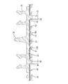
- FIG. 1 is an exploded perspective view showing a schematic configuration of a television receiver according to Embodiment 1.
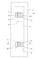
- FIG. Exploded perspective view showing schematic configuration of liquid crystal display device Sectional drawing which shows the state which cut
- Sectional drawing which shows the state which cut
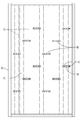
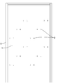
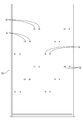
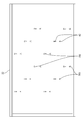
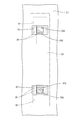
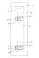
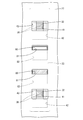
- Top view showing the lamp clip attached to the chassis The top view which shows the state by which the reflective sheet is arrange
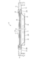
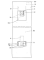
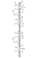
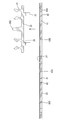
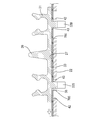
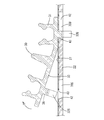
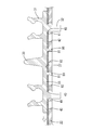
- BB sectional view of FIG. Partial enlarged sectional view showing a state in which a plurality of lamp clips are arranged at a fixed position and a reflection sheet is arranged at an initial position.
- Partial expanded sectional view which shows the state by which the several lamp clip is arrange
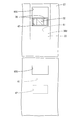
- Partially enlarged plan sectional view showing a state in which the lower lamp clip is arranged at the attachment / detachment position Partially enlarged plan sectional view showing a state in which the middle lamp clip is arranged at the attachment / detachment position
- Partially enlarged plan sectional view showing a state in which the upper lamp clip is arranged at the attachment / detachment position The top view of the chassis concerning Embodiment 3.
- the top view which shows the state by which the reflective sheet is arrange
- Partially enlarged plan sectional view showing a state in which the lower lamp clip is arranged at the attachment / detachment position
- Partially enlarged plan sectional view showing a state in which the upper lamp clip is arranged at the attachment / detachment position
- Partial enlarged sectional view showing a state in which all the lamp clips are arranged at the fixed position and the reflection sheet is arranged at the initial position. Partial enlarged sectional view showing a state in which the lower lamp clip is removed.
- Partial enlarged sectional view showing a state in which the upper lamp clip is removed.
- Partially enlarged plan sectional view showing a state in which the upper stage locking part and the lower stage locking part are arranged at the fixed position and the reflection sheet is arranged at the initial position.
- Sectional enlarged sectional view Partially enlarged plan sectional view showing a state in which the lower locking portion is disposed at the attachment / detachment position Partially enlarged plan sectional view showing a state where the lower locking portion is removed Partially enlarged plan sectional view showing a state in which the upper locking portion is disposed at the attachment / detachment position Partially enlarged plan sectional view showing a state in which the upper locking portion is removed
- Partial enlarged sectional drawing which shows the state by which the latching
- TV TV receiver
- 10 Liquid crystal display device (display device)
- 11 Liquid crystal panel (display panel)
- 20 Backlight device (illumination device)
- 21 Discharge tube (lamp)
- 22 Chassis
- 27 Reflection Sheet (optical sheet)
- 30 lamp clip, 31 ... lamp gripping part, 32 ... locking part, 33 ... base part, 41,70 ... locking hole, 42 ... through hole, 43, 50, 60 ... insertion hole, 80 ... auxiliary projection, 81 ... auxiliary hole, 82 ... receiving recess, 90 ... uneven contact portion
- the television receiver TV including the liquid crystal display device 10 (display device) is illustrated.
- the television receiver TV includes a liquid crystal display device 10, cabinets Ca and Cb that accommodate the liquid crystal display device 10 sandwiched from the front and back, a power source P, a tuner T for receiving television broadcasts, and the like. And a stand S.
- the liquid crystal display device 10 is housed in the cabinets Ca and Cb in a vertically placed posture with the display surface oriented in a substantially vertical direction.
- the liquid crystal display device 10 has a horizontally long rectangular shape as viewed from the front and back directions. As shown in FIG. 2, the liquid crystal panel 11 (corresponding to the display panel of the present invention) capable of displaying an image, and the liquid crystal panel 11 And a backlight device 20 (corresponding to the illumination device of the present invention) that is an external light source that irradiates light toward the head, and these are integrally held by a holding member such as a bezel 12.
- a holding member such as a bezel 12.
- the liquid crystal panel 11 includes a pair of transparent (translucent) glass substrates having a horizontally long rectangular shape, and a liquid crystal layer that is interposed between the two substrates and whose optical characteristics change with voltage application (see FIG. Not shown). Note that polarizing plates 11A and 11B are attached to the front and back surfaces of the liquid crystal panel 11 (see FIGS. 3 and 4).
- the liquid crystal panel 11 is fixed with a peripheral portion sandwiched between a bezel 12 arranged on the front side, a frame 13 and a holder 26 arranged on the back side.
- the bezel 12 and the frame 13 are made of metal (for example, aluminum), and the bezel 12 has a horizontally long frame shape along the peripheral edge of the liquid crystal panel 11 (surrounds the display area of the liquid crystal panel 11).
- the panel 11 has an elongated shape along an edge extending in the longitudinal direction of the peripheral edge of the panel 11.
- the holder 26 has a long and narrow shape along an edge extending in the short direction of the peripheral edge of the liquid crystal panel 11.
- the backlight device 20 is a so-called direct-type backlight device 20 and is provided immediately below the back surface of the liquid crystal panel 11.
- the backlight device 20 includes a chassis 22 in which a discharge tube 21 (corresponding to the lamp of the present invention) is arranged on the front side.
- the chassis 22 is made of metal and includes a flat bottom wall 22A and a peripheral wall 22B that rises from the peripheral edge of the bottom wall 22A to the front side, and has a shallow dish shape that opens to the front side as a whole.
- a fixing hole 23 is formed in the peripheral wall 22 ⁇ / b> B, the bezel 12, and the frame 13 of the chassis 22 so as to penetrate in the front and back direction.
- a screw (not shown) is inserted into the fixing hole 23 and tightened.
- the chassis 22, the bezel 12 and the frame 13 are integrated.
- the bottom wall 22A has a horizontally long rectangular shape that is slightly larger than the liquid crystal panel 11 in plan view. At both ends in the longitudinal direction of the bottom wall 22A, a plurality of attachment holes 24 for attaching a relay connector 25 described later are provided penetrating the bottom wall 22A in the front and back direction (see FIGS. 2 and 4).
- an inverter board B for controlling the driving of the discharge tube 21 and a control board C for controlling the driving of the liquid crystal panel 11 are attached (see FIG. 2).
- the inverter board B is disposed at both ends in the longitudinal direction of the chassis 22 and is electrically connected to the relay connector 25.
- the control board C is disposed at the center of the chassis 22 in the longitudinal direction.
- a diffusion plate 28 is disposed in the opening of the chassis 22.
- the diffuser plate 28 is obtained by dispersing and mixing light scattering particles in a synthetic resin plate-like member, and has a function of diffusing light from the discharge tube 21 that is a linear light source.
- the diffusion plate 28 has a horizontally long rectangular shape, and both edge portions extending in the longitudinal direction among the peripheral edge portions are sandwiched and fixed between the peripheral wall 22B of the chassis 22 and the frame 13 (see FIG. 3). In addition, the both edge parts extended in a transversal direction among the peripheral parts of the diffusion plate 28 are mounted on the holder 26 (refer FIG. 4).
- a sheet-like optical member 29 is provided on the front side of the diffusion plate 28.
- the optical member 29 is formed by laminating a plurality of sheets having different functions. For example, a diffusion sheet, a lens sheet, and a reflective polarizing plate are sequentially formed from the back side. The optical member 29 is sandwiched and held between the diffusion plate 28 and the liquid crystal panel 11.
- a reflection sheet 27 (corresponding to the optical sheet of the present invention) that reflects light from the discharge tube 21 to the front side (diffuser plate 28 side). ) Is laid.
- the reflection sheet 27 is made of synthetic resin, and the surface thereof is white with excellent reflectivity.
- the reflection sheet 27 has a horizontally long rectangular shape covering substantially the entire area along the surface (inner surface) of the bottom wall 22A of the chassis 22. ing. As shown in FIG. 3, both edges extending in the longitudinal direction of the peripheral edge of the reflection sheet 27 are formed so as to cover the front side of the peripheral wall 22 ⁇ / b> B of the chassis 22, and are sandwiched between the chassis 22 and the diffusion plate 28. Is fixed.
- a plurality of discharge tubes 21 that irradiate light toward the liquid crystal panel 11 are accommodated in the chassis 22 (portion surrounded by the bottom wall 22A and the peripheral wall 22B).
- the discharge tube 21 has an elongated tubular shape, and each axis is arranged in parallel at a predetermined interval so that the respective axes coincide with the long side direction of the chassis 22. Both end portions of the discharge tube 21 are fitted and fixed to the relay connector 25, respectively, and the intermediate portion is held by a lamp clip 30 described later.
- a plurality of relay connectors 25 are arranged along both edge portions in the longitudinal direction of the chassis 22 (see FIG. 2).
- the relay connector 25 is collectively covered with a holder 26.
- the holder 26 is made of white synthetic resin and has a long and narrow box shape.
- the backlight device 20 has a plurality of lamp clips 30 that hold the discharge tube 21.
- the lamp clip 30 is made of synthetic resin (for example, made of polycarbonate), and the surface thereof is white with excellent light reflectivity.
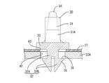
- the lamp clip 30 includes a lamp gripping portion 31 that grips the discharge tube 21, a locking portion 32 that locks the rear surface of the chassis 22, and a base portion 33 that sandwiches the chassis 22 and the reflection sheet 27 between the locking portions 32. (See FIG. 8).
- the base portion 33 has an elongated, substantially rectangular plate shape, and a support pin 34 that supports the diffusion plate 28 from the back side is provided to protrude to the front side at a substantially central position in the longitudinal direction.
- the support pin 34 has a substantially conical shape in which the diameter dimension gradually decreases toward the protruding end, and the protruding dimension is larger than the protruding dimension of the lamp gripping portion 31.
- the support pins 34 restrict the bending and warping of the diffusion plate 28 toward the back side (discharge tube 21 side).
- a pair of lamp gripping portions 31 are provided at both ends in the longitudinal direction of the base portion 33, and the interval between the pair of lamp gripping portions 31 matches the parallel pitch of the discharge tubes 21.
- Each lamp gripping portion 31 has a pair of arm portions 31A that sandwich the discharge tube 21, and has a substantially annular shape that opens to the front as a whole.
- the pair of arm portions 31A rises in a cantilevered manner from the base portion 33 to the front side, and can be elastically deformed in the approaching / separating direction.
- the lamp gripping portion 31 is provided so that the facing direction of the pair of arm portions 31 ⁇ / b> A coincides with the longitudinal direction of the base portion 33.
- the arm portion 31A is curved in a substantially arc shape.
- a pair of holding projections 31B projecting inward are provided at positions closer to the tips of the pair of arm portions 31A, and the pair of holding projections 31B are substantially half on the front side of the discharge tube 21 gripped by the lamp gripping portion 31. It comes to contact the part. Further, the opposing surfaces of the tip portions of the pair of arm portions 31A (end portions on the front side of the holding projections 31B) are guide surfaces 31C that are inclined so that the distance between the tips gradually increases toward the tips. The guide surface 31C guides the mounting operation of the discharge tube 21.
- a pair of locking portions 32 are provided on the back surface of the base portion 33, and the pair of locking portions 32 are disposed at both ends in the longitudinal direction of the base portion 33 (positions directly behind the pair of lamp gripping portions 31).
- the locking portion 32 has a base portion 32A that protrudes from the base portion 33 to the back side, and a pair of locking legs 32B that cantilever from the base portion 32A and protrude to the back side.
- the base portion 32A of the locking portion 32 has a columnar shape with a substantially rectangular cross section, and its axial dimension (front and rear direction dimension) is slightly larger than the sum of the thickness dimension of the chassis 22 and the thickness dimension of the reflection sheet 27. The dimensions are small (see FIGS. 10 and 12).
- the base portion 32A of the locking portion 32 is located at the center in the facing direction of the pair of arm portions 31A of the lamp gripping portion 31 (see FIGS. 13 and 14).
- the pair of locking legs 32B are opposed to each other from the back surface of the base portion 32A and protrude to the back side (see FIGS. 10 and 12).
- the pair of locking legs 32 ⁇ / b> B are provided at a predetermined interval, and can be elastically displaced in the approaching / separating direction (short direction of the base portion 33).
- the distal ends of the pair of locking legs 32B are extended portions 35 that project outward.
- the overhang portion 35 When viewed from the longitudinal direction of the base portion 33, the overhang portion 35 has a wedge shape that sharpens toward the tip.
- the width dimension of both the locking legs 32B (the width dimension in the direction along the longitudinal direction of the base portion 33) is equal to the width dimension of the base portion 32A in the same direction, and is substantially constant from the base to the tip.
- a pair of locking legs 32B is formed with a locking surface 36 that locks to the back surface of the chassis 22.
- the locking surface 36 is the front side surface of the overhang portion 35 and is substantially parallel to the back surface of the base portion 33 (see FIGS. 10 and 12).
- a dimension equivalent to the dimension obtained by adding the thickness dimension of the chassis 22 and the thickness dimension of the reflection sheet 27 is opened between the locking surface 36 and the base portion 33.
- the locking surface 36 projects in a symmetrical direction from the base portion 32A, and as shown in FIG.
- the base portion 32 ⁇ / b> A has a substantially rectangular shape that is long in the short direction of the base portion 33.
- all the lamp clips 30 are arranged so that the longitudinal direction of the base portion 33 coincides with the parallel direction of the discharge tubes 21 (substantially orthogonal to the axial direction of the discharge tubes 21), and the longitudinal direction of the chassis 22. It is distributed and attached to the middle part.
- a locking hole 41 for locking the locking portion 32 of the lamp clip 30 is provided in the bottom wall 22A of the chassis 22 (see FIG. 7).
- the locking hole 41 is formed at the attachment position of the lamp clip 30 in the bottom wall 22A of the chassis 22 so as to penetrate the bottom wall 22A in the front and back direction.
- Two locking holes 41 are arranged with respect to one lamp clip 30 at an interval equal to the interval between the pair of locking portions 32 of each lamp clip 30.
- All the locking holes 41 are formed in substantially the same shape and size and have a rectangular shape slightly longer in the vertical direction (short direction of the chassis 22). As shown in FIGS. 9 and 10, the width dimension of the locking hole 41 in the short direction is substantially the same as the width dimension of the base portion 32A of the locking portion 32 (the width dimension of the locking leg 32B in the opposite direction). Is set to And the locking surface 36 of the latching
- locking part 32 latches from the back side to the both edge parts which oppose the transversal direction of the latching hole 41 among the hole edges of each latching hole 41. As shown in FIG. .
- the chassis 22 is provided with a through hole 42 having a larger hole area than the locking hole 41.
- the through holes 42 are provided in a continuous manner in the respective locking holes 41, and the locking portions 32 of the lamp clip 30 have a fixed position positioned in the locking holes 41 and an attachment / detachment position positioned in the through holes 42. It is possible to move between.
- the through holes 42 are provided corresponding to all the locking holes 41, and all the through holes 42 have substantially the same shape and size.
- the through hole 42 has such a size that it can be passed through in the front and back direction without deforming the engaging portion 32 in a reduced diameter, that is, without deforming the engaging leg 32B in the approaching direction, in other words, in the natural state.
- the size is set to be slightly larger than the outer shape of the stopper 32 in plan view (see FIG. 11).
- Each through hole 42 has a substantially rectangular shape that is long in the longitudinal direction of the chassis 22. As shown in FIG. 9, the width dimension in the longitudinal direction of the through hole 42 is smaller than the width dimension in the short direction of the base part 33, and the width dimension in the short direction of the through hole 42 is the length of the base part 33. It is made smaller than the dimension between the end edge in the direction to the locking part 32. And all the through-holes 42 are arrange
- All the through holes 42 are formed below the locking holes 41, and the through holes 42 have a form that is wider than the locking holes 41 by the same dimension in the left-right direction (longitudinal direction of the chassis 22).
- the locking portions 32 of all the lamp clips 30 are moved downward from the fixed position to the mounting / dismounting position, and moved upwardly from the mounting / dismounting position to the fixing position. The amount of movement between the fixed position and the attachment / detachment position is the same.
- the reflection sheet 27 is formed with an insertion hole 43 through which the locking portion 32 is inserted in the front and back direction.
- the insertion hole 43 is formed at the attachment position of the lamp clip 30 in the reflection sheet 27 (see FIG. 6).
- Two insertion holes 43 are provided with respect to one lamp clip 30 at an interval equal to the interval between the pair of locking portions 32 of each lamp clip 30.
- All the insertion holes 43 are formed to have substantially the same shape and size, are larger than the locking holes 41, and have a rectangular shape slightly longer in the left-right direction (longitudinal direction of the chassis 22). Similar to the through hole 42, the insertion hole 43 is set to a size that allows the engaging portion 32 to pass in the front and back direction without reducing the diameter of the engaging portion 32, that is, without deforming the engaging leg 32B in the approaching direction. Has been. A pair of edges extending in the longitudinal direction among the hole edges of the insertion hole 43 (a pair of edges facing the sliding direction of the reflection sheet 27) are along the outer edge of the base portion 32 ⁇ / b> A of the locking part 32 inserted through the insertion hole 43. Is located (see FIGS. 9 and 11).
- the reflection sheet 27 is slidable in the direction along the moving direction of the locking portion 32 from the initial position where the insertion hole 43 is continuous with the locking hole 41.
- the reflection sheet 27 moves downward from the initial position to reach a position where the insertion hole 43 is continuous with the through hole 42 (referred to as an end position).
- the insertion hole 43 is arranged so as to be shifted from the through hole 42 and restricts the passage of the locking portion 32 in the front and back direction. It prevents moving to 42 side and inadvertently leaving.
- the reflection sheet 27 is in the final position, as shown in FIG. 11, the insertion hole 43 is continuous with the through hole 42 and allows the locking portion 32 to pass through in the front and back direction.
- all the insertion holes 43 are connected to all the through holes 42, and when the reflection sheet 27 is in the initial position, all the insertion holes 43 are displaced from all the through holes 42. .
- the reflection sheet 27 is disposed on the front side of the chassis 22. Specifically, the reflective sheet 27 is aligned and disposed at the initial position so that each insertion hole 43 is disposed on the front side of each locking hole 41.
- each lamp clip 30 is aligned so that the pair of locking portions 32 face the insertion holes 43 of the reflection sheet 27, and the lamp clip 30 is brought closer to the chassis 22 side.
- the locking leg 32 ⁇ / b> B of the locking part 32 passes through the insertion hole 43 and contacts the hole edge of the locking hole 41.
- the locking leg 32 is elastically deformed in the reduced diameter direction by the pressing of the locking leg 32 against the hole edge of the locking hole 41 and is inserted into the locking hole 41, and then the chassis. It will be in the state protruded to the back side of 22.
- the locking leg 32 is elastically restored, and the entire pair of locking surfaces 36 are in a state (locked state) arranged on the back side of the hole edge of the locking hole 41. In this way, all the lamp clips 30 are attached to the chassis 22 in a non-removable state.
- the discharge tube 21 is attached to the chassis 22 in order. Both ends of each discharge tube 21 are fitted to the relay connector 25, and the intermediate part is held by the lamp holding part 31 of each lamp clip 30.
- the holder 26 is put on the relay connector 25, and the diffusion plate 28 and the optical member 29 are placed on the opening of the chassis 22. Then, a pair of frames 13 are installed at predetermined positions, and a separately manufactured liquid crystal panel 11 and bezel 12 are placed in order on the front side, and the bezel 12, the frame 13 and the chassis 22 are screwed together to be integrated. Thus, the assembly of the liquid crystal display device 10 is completed.
- the discharge tube 21 is removed from the chassis 22 in order. Both end portions of each discharge tube 21 are detached from the relay connector 25 and the intermediate portion is removed from the lamp gripping portion 31 of each lamp clip 30.
- the reflection sheet 27 is slid from the initial position to the lower side (end position side).
- the upper edge of the insertion hole 43 (the edge of the hole of the insertion hole 43 on the rear side in the sliding direction toward the end position side) is the upper edge of the base portion 32A of the locking portion 32 at the fixed position (the base portion 32A).
- the outer edge is located along the rear edge in the movement direction toward the attachment / detachment position. For this reason, the upper edges of all the insertion holes 43 come into contact with the upper edges of the base portions 32A of the locking portions 32 immediately after the reflection sheet 27 starts to slide, and the base portions 32A are lowered as the reflection sheets 27 slide further. Press to the side (detachment position side).
- each locking portion 32 moves from the locking hole 41 to the through hole 42 side, and the locking surface 36 of each locking portion 32 is gradually exposed from the back side of the chassis 22.
- the reflection sheet 27 reaches the final position, the insertion hole 43 moves to the front side of the through hole 42, and is connected to the entire through hole 42.
- the lamp clip 30 reaches the attaching / detaching position, and the entire base portion 32A of the locking portion 32 moves to the through hole 42, and the entire pair of locking surfaces 36 face the front side from the through hole 42 (unlocked). State). In this way, all the lamp clips 30 can be attached from the chassis 22.
- the lamp clips 30 are removed from the chassis 22 in order.
- the support pin 34 of the lamp clip 30 is grasped with the fingertip and pulled to the front side, the locking portion 32 smoothly passes through the insertion hole 43 from the through hole 42 without being elastically deformed, and is removed from the chassis 22. In this way, the dismantling operation of the liquid crystal display device 10 is completed.
- the lamp clip 30 is provided with a locking portion 32 that is locked from the back side to the hole edge portion of the locking hole 41 formed in the chassis 22 through the insertion hole 43 formed in the reflection sheet 27.
- a through hole 42 having a larger hole area than the locking hole 41 is provided continuously from the locking hole 41, and the locking part 32 is provided at a fixed position located in the locking hole 41 and the through hole 42.
- the insertion hole 43 of the reflection sheet 27 has a larger hole area than the locking hole 41, and the reflection sheet 27 has the insertion hole 43 connected to the locking hole 41. It is slidable in the direction along the moving direction of the locking part 32 from the initial position.
- the reflecting sheet 27 is slid from the initial position, and the engaging portion 32 is moved from the fixed position to the attaching / detaching position, so that the engaging portion is removed from the through hole 42 and the insertion hole 43. 32 can be pulled out to the front side. Since the through hole 42 and the insertion hole 43 have a larger hole area than the locking hole 41, the through hole 42 and the insertion hole 43 can be easily pulled out as compared with the conventional case where the locking portion is pulled out from the locking hole. Can be removed.
- the edge of the rear side in the sliding direction among the hole edges of the insertion hole 43 of the reflection sheet 27 arranged at the initial position is attached / detached among the outer edges of the locking portion 32 arranged at the fixed position. It is set so as to be located along the edge on the rear side in the moving direction to the position side.
- the through hole 42 of the chassis 22 is disposed in the projection plane of the base portion 33 with respect to the chassis 22 in a state where the lamp clip 30 is in the fixed position. Thereby, it is possible to prevent light from the discharge tube 21 from leaking from the through hole 42 of the chassis 22.
- the through hole 42 and the insertion hole 43 are set to a size that allows the locking portion 32 to pass through in the front and back direction without being deformed in a reduced diameter. Thereby, when pulling out the locking portion 32, the force required for pulling out the lamp clip 30 is remarkably reduced as compared with a case where the diameter of the lamp clip 30 needs to be reduced, so that the lamp clip 30 can be easily detached. be able to.
- a plurality of lamp clips 30 are provided, and the plurality of lamp clips 30 have the same moving direction from the fixing position of the locking portion 32 to the attaching / detaching position side.
- the reflecting sheet 27 is slid from the initial position, all the lamp clips 30 can be moved from the fixed position to the attaching / detaching position at the same time, so that the workability for removing the lamp clip 30 can be improved. it can.
- Embodiment 2 a television receiver TV according to Embodiment 2 embodying the present invention will be described with reference to FIGS.
- the television receiver TV of the present embodiment is different from the first embodiment in that the size of the insertion hole 50 is set to be different between the lamp clips 30.
- symbol is attached
- the television receiver TV includes the liquid crystal panel 11 and the backlight device 20 as in the first embodiment.
- the backlight device 20 holds the discharge tube 21, the chassis 22 in which the discharge tube 21 is disposed on the front side, the reflection sheet 27 disposed between the discharge tube 21 and the chassis 22, as in the first embodiment. And a lamp clip 30.
- the chassis 22 is provided with a locking hole 41 for locking the locking portion 32 of the lamp clip 30 as in the first embodiment. All the locking holes 41 are formed in substantially the same shape and the same size as in the first embodiment. Of the edge portions of the respective locking holes 41, both edge portions facing in the left-right direction are provided with the locking portions 32. The locking surface 36 is locked from the back side. Further, as in the first embodiment, the chassis 22 is provided with a through hole 42 having a larger hole area than the locking hole 41 and extends from the locking hole 41, and the locking portion 32 of the lamp clip 30 is connected to the chassis 22. It is movable between a fixed position located in the stop hole 41 and an attachment / detachment position located in the through hole 42.
- the reflection sheet 27 is slidable in the direction along the moving direction of the locking portion 32 from the initial position where the insertion hole 50 continues to the locking hole 41.
- two insertion holes 50 are provided at two attachment positions of one lamp clip 30 with an interval equal to the interval between the pair of locking portions 32 of each lamp clip 30.
- the insertion hole 50 is set so that the width dimension in the direction along the sliding direction (vertical direction) of the reflection sheet 27 differs between the lamp clips 30. Specifically, the insertion hole 50 is different in size for each insertion hole 50 formed in a predetermined region of the reflection sheet 27. In the present embodiment, the reflection sheet 27 is divided into three regions in the vertical direction. Of these, the insertion hole 50 (referred to as the upper insertion hole 50U) disposed in the uppermost region, the insertion hole 50 (referred to as the middle insertion hole 50N) disposed in the middle region, and the lowermost region.
- the insertion holes 50 (referred to as lower insertion holes 50S) have different sizes. Note that the vertical dimension of the lower insertion hole 50S is the smallest, and the vertical dimension of the insertion hole 50 formed in the upper region is set to be larger.
- the lower insertion hole 50S has a hole area larger than that of the locking hole 41 and has a rectangular shape slightly longer in the left-right direction (longitudinal direction of the chassis 22). Similarly to the through hole 42 formed in the chassis 22, the lower insertion hole 50 ⁇ / b> S allows the locking part 32 to pass in the front and back direction without reducing the diameter of the locking part 32, that is, without changing the locking leg 32 ⁇ / b> B in the approaching direction. Is set to a possible size.
- the vertical dimension of the middle insertion hole 50N is approximately twice the vertical dimension of the lower insertion hole 50S
- the vertical dimension of the upper insertion hole 50U is the vertical dimension of the lower insertion hole 50S.
- the size is about three times the width. Note that the width dimensions in the left-right direction of the upper stage insertion hole 50U, the middle stage insertion hole 50N, and the lower stage insertion hole 50S are all equal.
- a pair of edges opposed in the vertical direction among the hole edges of the lower insertion hole 50S (a pair opposed to the sliding direction of the reflection sheet 27). Is located along the outer edge of the base portion 32A of the locking portion 32 inserted through the lower insertion hole 50S.
- the pair of edges facing vertically in the middle stage insertion hole 50N are positioned along the outer edge of the base portion 32A of the locking part 32 whose lower edge is inserted into the middle stage insertion hole 50N. Is positioned away from the outer edge of the base portion 32A of the locking portion 32.
- the distance between the upper edge of the middle-stage insertion hole 50N and the outer edge of the base portion 32A is set to be equal to or slightly larger than the width dimension in the vertical direction of the base portion 32A.
- a pair of edge which opposes an up-down direction among the hole edges of the upper stage insertion hole 50U is located along the outer edge of the base 32A of the latching
- the interval between the upper edge of the upper insertion hole 50U and the outer edge of the base portion 32A is set to a size that is approximately twice the vertical width of the base portion 32A.
- the hole edge of the insertion hole 50 of the reflection sheet 27 arranged at the initial position the edge on the rear side in the sliding direction, and the attaching / detaching position of the outer edges of the engaging portions 32 of all the lamp clips 30 arranged at the fixed position.
- the distance from the rear edge in the moving direction to the side is set to be different between the lamp clips 30.
- the lamp clip 30 attached to the uppermost region of the reflection sheet 27 is the upper lamp clip 30U
- the lamp clip 30 attached to the middle region is the middle lamp clip 30N
- the lamp clip 30 is attached to the lower region. Is referred to as a lower lamp clip 30S.
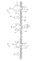
- the reflection sheet 27 is slid downward from the initial position. Then, immediately after the reflection sheet 27 starts to slide, the upper edge of the lower insertion hole 50S is the upper edge of the base portion 32A of the locking portion 32 of the lower lamp clip 30S (the outer edge of the rear side in the movement direction to the attachment / detachment position side). ) And press the base 32A downward (attachment / detachment position side) as the reflective sheet 27 slides further. Then, the base portion 32A of the locking portion 32 of each lower lamp clip 30S pushed to the upper edge of the lower insertion hole 50S moves from the locking hole 41 toward the through hole 42 and eventually reaches the attachment / detachment position (see FIG. 17). ).
- the locking portions 32 of the middle lamp clip 30N and the upper lamp clip 30U are not pushed by the middle stage insertion hole 50N and the upper stage insertion hole 50U, and are all held in the fixed position.
- the upper edge of the hole edge of the middle stage insertion hole 50N is along the outer edge of the base part 32A of the locking part 32 inserted through the middle stage insertion hole 50N, and the lower edge is separated downward from the outer edge of the base part 32A of the locking part 32. Is located.
- the distance between the lower edge of the middle insertion hole 50N and the outer edge of the base portion 32A is set to be equal to or slightly larger than the width dimension in the vertical direction of the base portion 32A.
- the reflection sheet 27 is further slid downward.
- the upper edge of the middle stage insertion hole 50N is the upper edge of the base part 32A of the locking part 32 of the middle stage lamp clip 30N (the outer edge of the rear side in the movement direction to the attachment / detachment position side). )
- the base portion 32A of the locking portion 32 of each middle lamp clip 30N pushed to the upper edge of the middle insertion hole 50N moves from the locking hole 41 toward the through hole 42 and eventually reaches the attachment / detachment position (see FIG. 18). .
- the locking portions 32 of the upper lamp clip 30U are all disposed at the fixed position without being pushed by the upper insertion hole 50U.
- the upper edge of the hole edge of the upper insertion hole 50U is along the outer edge of the base portion 32A of the locking portion 32 inserted through the upper insertion hole 50U, and the lower edge is separated downward from the outer edge of the base portion 32A of the locking portion 32. Is located.
- the reflection sheet 27 is further slid downward.
- the upper edge of the upper insertion hole 50U is the upper edge of the base portion 32A of the engaging portion 32 of the upper lamp clip 30U (the outer edge of the rear side in the movement direction to the attachment / detachment position side). )
- the base portion 32A of the locking portion 32 of each upper lamp clip 30U pushed to the upper edge of the upper insertion hole 50U moves from the locking hole 41 to the through hole 42 side and eventually reaches the attachment / detachment position (see FIG. 19).
- all the upper lamp clips 30U are ready to be attached from the chassis 22 in this manner, all the upper lamp clips 30U are removed from the chassis 22.
- the removal work of all the lamp clips 30 attached to the chassis 22 is completed.
- the reflective sheet 27 is slid from the initial position and the lamp clip 30 is moved from the fixed position to the detachable position as in the first embodiment. Since the locking portion 32 can be pulled out from the through hole 42 and the insertion hole 50 to the front side, the lamp clip 30 can be easily removed.
- the distance between the side edges is set to be different between the lamp clips 30.
- the reflection sheet 27 pushes the lamp clips 30 in order, even if the number of the lamp clips 30 attached to the chassis 22 increases, the force acting on the reflection sheet 27 is increased. Thus, the lamp clip 30 can be easily removed.
- the television receiver TV of the present embodiment is different from the first embodiment in that the moving direction from the fixed position of the locking portion 32 to the attaching / detaching position side is set to be different between the lamp clips 30.
- symbol is attached
- the television receiver TV includes the liquid crystal panel 11 and the backlight device 20 as in the first embodiment.
- the backlight device 20 holds the discharge tube 21, the chassis 22 in which the discharge tube 21 is disposed on the front side, the reflection sheet 27 disposed between the discharge tube 21 and the chassis 22, as in the first embodiment. And a lamp clip 30.
- the chassis 22 is provided with a locking hole 41 for locking the locking portion 32 of the lamp clip 30 as in the first embodiment. All the locking holes 41 are formed in substantially the same shape and the same size as in the first embodiment. Of the edge portions of the respective locking holes 41, both edge portions facing in the left-right direction are provided with the locking portions 32. The locking surface 36 is locked from the back side.
- the chassis 22 is provided with a through hole 42 having a larger hole area than the locking hole 41 and extends from the locking hole 41, and the locking portion 32 of the lamp clip 30 is connected to the chassis 22. It is movable between a fixed position located in the stop hole 41 and an attachment / detachment position located in the through hole 42.
- the through-holes 42 are provided continuously in the respective locking holes 41, and all the through-holes 42 have substantially the same shape and size, so that the diameter of the locking portion 32 is not reduced and deformed. It is set to a size that can be passed in the front and back direction.
- the through holes 42 are formed at different positions with respect to the locking holes 41 between the through holes 42 arranged in the upper region of the reflection sheet 27 and the through holes 42 arranged in the lower region. (See FIG. 20). That is, the through hole 42 disposed in the upper region is formed above the locking hole 41, and the through hole 42 disposed in the lower region is formed below the locking hole 41, and is disposed in the upper region.
- the locking hole 41 and the through hole 42 thus formed, and the locking hole 41 and the through hole 42 arranged in the lower region are formed in a shape that is opposite in the vertical direction.
- the locking portion 32 of the lamp clip 30 (referred to as the upper lamp clip 30U) attached to the upper area of the reflection sheet 27 is moved upward to reach the attachment / detachment position, and is attached to the lower area.
- the locking portion 32 of the lamp clip 30 (referred to as the lower lamp clip 30S) is moved downward from the fixed position to the attachment / detachment position.
- the reflection sheet 27 is slidable in the direction along the moving direction of the locking portion 32 from the initial position where the insertion hole 60 is continuous with the locking hole 41.
- two insertion holes 60 are provided at two attachment positions of one lamp clip 30 with an interval equal to the interval between the pair of locking portions 32 of each lamp clip 30.
- the width of the insertion hole 60 in the direction along the sliding direction (vertical direction) of the reflection sheet 27 is different for each insertion hole 60 formed in a predetermined region of the reflection sheet 27.
- the insertion hole 60 (referred to as the upper insertion hole 60U) disposed in the upper region of the reflection sheet 27 and the insertion hole 60 (referred to as the lower insertion hole 60S) disposed in the lower region.
- the sizes are different from each other.
- the lower insertion hole 60S has a hole area larger than that of the locking hole 41, has a slightly longer rectangular shape in the left-right direction (longitudinal direction of the chassis 22), and reduces the diameter of the locking portion 32. It is set to a size that allows it to pass through in the front and back direction.
- the vertical width dimension of the upper insertion hole 60U is larger than the vertical dimension of the lower insertion hole 60S, and specifically, approximately twice the vertical dimension of the lower insertion hole 60S. It is said that.
- a pair of edges facing in the vertical direction (a pair of edges facing the sliding direction of the reflection sheet 27) among the hole edges of the lower insertion hole 60 ⁇ / b> S. ) Is located along the outer edge of the base portion 32A of the locking portion 32 of the lower lamp clip 30S locked in the locking hole 41.
- a pair of vertically opposed edges of the upper insertion hole 60U is positioned along the outer edge of the base portion 32A of the locking portion 32 of the upper lamp clip 30U whose lower edge is locked to the locking hole 41.
- the upper edge is located away from the outer edge of the base portion 32 ⁇ / b> A of the locking portion 32. At this time, the interval between the upper edge of the upper insertion hole 60U and the outer edge of the base portion 32A is set to be equal to or slightly larger than the vertical dimension of the base portion 32A.
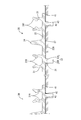
- the reflection sheet 27 is slid downward from the initial position. Then, immediately after the reflection sheet 27 starts to slide, the upper edge of the lower insertion hole 60S is the upper edge of the base portion 32A of the locking portion 32 of the lower lamp clip 30S (the outer edge of the rear side in the movement direction to the attachment / detachment position side). ) And press the base 32A downward (attachment / detachment position side) as the reflective sheet 27 slides further. Then, the base portion 32A of the locking portion 32 of each lower lamp clip 30S moves from the locking hole 41 to the through hole 42 side and eventually reaches the attachment / detachment position (see FIG. 23).
- the reflection sheet 27 is slid upward. Then, the upper stage insertion hole 60U moves relatively upward with respect to the locking part 32 of the upper stage lamp clip 30U, and the lower edge of the upper stage insertion hole 60U eventually reaches the base 32A of the locking part 32 of the upper stage lamp clip 30U.
- the reflection sheet 27 is further slid along the outer edge, the lower edge of the upper insertion hole 60U comes into contact with the lower edge of the base portion 32A of the locking portion 32 of the upper lamp clip 30U and moves upward (to the attachment / detachment position side). Press.
- the reflective sheet 27 is slid from the initial position and the locking portion 32 is moved from the fixed position to the detachable position, as in the first embodiment.
- the locking portion 32 can be pulled out from the through hole 42 and the insertion hole 60 to the front side, and the lamp clip 30 can be easily removed.
- a plurality of lamp clips 30 are provided, and the moving direction from the fixing position of the locking portion 32 to the attaching / detaching position side is set to be different between the upper lamp clip 30U and the lower lamp clip 30S. Accordingly, the reflecting sheet 27 is slid in different directions, specifically, slid downward and then slid upward, so that the locking portion 32 of the lower lamp clip 30S and the locking portion 32 of the upper lamp clip 30U are moved. In order, move from the fixed position to the attach / detach position. Therefore, even if the number of the lamp clips 30 attached to the chassis 22 is increased, the force acting on the reflection sheet 27 can be dispersed, so that the lamp clip 30 can be easily removed.
- a television receiver TV according to a fourth embodiment embodying the present invention will be described with reference to FIGS.
- the television receiver TV of the present embodiment is implemented in that the moving direction from the fixing position of the locking portion 32 provided on the lamp clip 30 to the attaching / detaching position side is set to be different between the locking portions 32. This is different from Form 1.
- symbol is attached
- the television receiver TV includes the liquid crystal panel 11 and the backlight device 20 as in the first embodiment.
- the backlight device 20 holds the discharge tube 21, the chassis 22 in which the discharge tube 21 is disposed on the front side, the reflection sheet 27 disposed between the discharge tube 21 and the chassis 22, as in the first embodiment. And a lamp clip 30.
- the chassis 22 is provided with a locking hole 70 for locking the locking portion 32 of the lamp clip 30 as in the first embodiment.
- two locking holes 70 are provided at the attachment positions of the lamp clips 30 in the bottom wall 22A of the chassis 22.
- the pair of locking holes 70 provided at the mounting positions of the lamp clips 30 are different in size.
- the width dimension in the vertical direction of the upper locking hole 70 (referred to as the upper locking hole 70 ⁇ / b> U) of the pair of locking holes 70 provided at the mounting position of each lamp clip 30 is the width of each lamp clip 30. It is set to be larger than the vertical dimension of the lower locking hole 70 (referred to as the lower locking hole 70S) of the pair of locking holes 70 provided at the mounting position.
- the upper locking hole 70U has a vertical dimension that is approximately twice that of the lower locking hole 70S.
- the width dimension in the left-right direction of the upper stage locking hole 70U and the lower stage locking hole 70S is the same, and the locking part 32 is provided at both edge parts facing each other in the left-right direction among the hole edges of each locking hole 70.
- the locking surface 36 is locked from the back side.
- the chassis 22 is provided with a through hole 42 having a larger hole area than the locking hole 70, extending from the locking hole 70, and the locking portion 32 of the lamp clip 30 is engaged. It is possible to move between a fixed position located in the stop hole 70 and an attachment / detachment position located in the through hole 42.
- All the through holes 42 have substantially the same shape and the same size as in the first embodiment, and are set to a size that allows the locking portion 32 to pass through in the front and back directions without being deformed by a reduced diameter.
- the pair of through holes 42 provided at the attachment positions of the lamp clips 30 are different from each other in the formation positions with respect to the locking holes 70. That is, of the pair of through holes 42, the upper through hole 42 is formed above the upper locking hole 70U, and the lower through hole 42 is formed below the lower locking hole 70S. Thereby, the moving direction from the fixing position of the locking part 32 to the attaching / detaching position side is set to be different between the pair of locking parts 32 provided in each lamp clip 30 (in the opposite direction).
- the locking portion 32 (referred to as the upper locking portion 32U) that locks in the upper locking hole 70U in each lamp clip 30 reaches the detaching position from the fixed position by moving upward, and the lower locking hole 70S.
- the locking portion 32 (the lower locking portion 32S) that is locked to the position is moved downward from the fixed position to the detachable position.
- the base portion 32A of the lower locking portion 32S of each lamp clip 30 is disposed at a substantially central position of the lower locking hole 70S when in the fixed position, and the base portion 32A of the upper locking portion 32U is When in the fixed position, it is disposed at a position closer to the upper side of the upper locking hole 70U (a position above the center position in the vertical direction of the upper locking hole 70U). And the dimension equivalent to the width dimension of the up-down direction of 32 A of base parts is vacated below the base part 32A of the upper stage latching
- the reflection sheet 27 is provided with two insertion holes 43 for inserting the locking portions 32 in the front and back directions, one for each lamp clip 30.
- All the insertion holes 43 are formed in substantially the same shape and the same size as in the first embodiment, and are set to a size that allows the locking portion 32 to pass through in the front and back directions without being deformed by a reduced diameter.
- a pair of edges extending in the longitudinal direction among the hole edges of the insertion hole 43 are along the outer edge of the base portion 32 ⁇ / b> A of the locking part 32 inserted through the insertion hole 43. positioned.
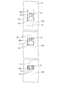
- the reflection sheet 27 is slid downward from the initial position. Then, immediately after the reflection sheet 27 starts to slide, the upper edge of each insertion hole 43 comes into contact with the upper edge of the upper locking portion 32U of the lamp clip 30 and the base portion 32A of the lower locking portion 32S. The base 32A is pressed downward (attachment / detachment position side) with the slide. Then, the base 32A of the lower locking portion 32S of the lamp clip 30 pushed by the upper edge of the insertion hole 43 moves from the lower locking hole 70S to the through hole 42 side, and eventually reaches the attachment / detachment position (see FIG. 31). .
- the reflection sheet 27 is slid upward. Then, immediately after the reflection sheet 27 starts to slide, the lower edge of the insertion hole 43 is moved to the lower edge of the base 32A of the upper stage locking portion 32U of each lamp clip 30 (rear side of the outer edge in the movement direction to the attachment / detachment position side) The base 32A is pushed upward (attachment / detachment position side) as the reflective sheet 27 slides further. Then, the base portion 32A of the upper locking portion 32U of each lamp clip 30 pushed by the lower edge of the insertion hole 43 passes through the upper locking hole 70U and moves to the through hole 42 side, and eventually reaches the attachment / detachment position. (See FIGS. 33 and 34). Thus, when the upper locking portions 32 of all the lamp clips 30 can be attached from the chassis 22, all the upper locking portions 32 ⁇ / b> U are pulled out from the chassis 22. Thereby, the removal work of all the lamp clips 30 attached to the chassis 22 is completed.
- the reflective sheet 27 is slid from the initial position and the locking portion 32 is moved from the fixed position to the detachable position, as in the first embodiment.
- the locking portion 32 can be pulled out from the through hole 42 and the insertion hole 43 to the front side, and the lamp clip 30 can be easily removed.
- the lamp clip 30 is provided with an upper locking portion 32U and a lower locking portion 32S, and the moving direction from the fixed position to the attachment / detachment position side is between the upper locking portion 32U and the lower locking portion 32S.
- the reflective sheet 27 is slid in different directions. Specifically, it must be slid downward and then slid upward.
- the moving direction from the fixed position to the attachment / detachment position is the same in the upper stage locking part and the lower stage locking part, all the locking parts are reflected by sliding the reflective sheet in one direction.
- the lamp clip 30 may be unintentionally removed by being pushed by the sheet and moving toward the attachment / detachment position.
- the moving direction from the fixed position to the attachment / detachment position side is set to be different between the upper stage locking part 32U and the lower stage locking part 32S, the lamp clip 30 is inadvertently removed as such. Can be prevented.
- the lamp clip 30 is provided with an auxiliary projection 80 that protrudes toward the reflection sheet 27, and the reflection sheet 27 is provided with an auxiliary hole 81 that engages with the auxiliary projection 80.
- symbol is attached
- the television receiver TV includes the liquid crystal panel 11 and the backlight device 20 as in the first embodiment.
- the backlight device 20 holds the discharge tube 21, the chassis 22 in which the discharge tube 21 is disposed on the front side, the reflection sheet 27 disposed between the discharge tube 21 and the chassis 22, as in the first embodiment. And a lamp clip 30.
- the chassis 22 is provided with a locking hole 41 for locking the locking portion 32 of the lamp clip 30, and a through hole 42 having a larger hole area than the locking hole 41 is locked. It is provided continuously from the hole 41. Further, as in the first embodiment, the reflection sheet 27 is formed with an insertion hole 43 through which the locking portion 32 is inserted in the front and back direction.
- the lamp clip 30 includes the lamp gripping portion 31 that grips the discharge tube 21, the locking portion 32 that locks to the back surface of the chassis 22, and the chassis 22 and the reflective sheet between the locking portions 32. 27 and a base portion 33 that sandwiches 27.
- the lamp clip 30 is provided with an auxiliary projection 80 that protrudes to the back side (the reflection sheet 27 side).
- a pair of auxiliary protrusions 80 are provided on the back surface of the base portion 33, and the pair of auxiliary protrusions 80 are located between the pair of locking portions 32.
- the pair of auxiliary protrusions 80 have substantially the same shape and size, and each auxiliary protrusion 80 has a wall shape with a substantially rectangular cross section (a rectangle that is long in the short direction of the base portion 33). Further, the projecting dimension (front / back direction dimension) of each auxiliary projection 80 is larger than the thickness dimension of the reflection sheet 27, and each auxiliary projection 80 projects to the chassis 22 side.
- the pair of auxiliary projections 80 project opposite to each other, and the opposed surfaces are substantially parallel.
- the reflection sheet 27 is provided with an auxiliary hole 81 that engages with the auxiliary protrusion 80.
- a pair of auxiliary holes 81 are formed between the insertion holes 43 in the reflection sheet 27, and are formed at positions corresponding to the auxiliary protrusions 80 in a state where the locking portions 32 are inserted into the insertion holes 43.
- the pair of auxiliary holes 81 are formed in substantially the same shape and size, have a rectangular shape that is slightly larger than the auxiliary protrusion 80, and penetrate the reflection sheet 27 in the front and back direction.
- a pair of edges facing the sliding direction of the reflection sheet 27 among the hole edges of the auxiliary holes 81 are located along the outer edges of the auxiliary protrusions 80 engaged with the auxiliary holes 81.
- the chassis 22 is provided with an accommodation recess 82 for accommodating the protruding end of the auxiliary projection 80.
- the housing recess 82 is a hole that penetrates the chassis 22 in the front and back direction.
- the housing recess 82 is provided between the upper through hole 42 and the lower locking hole 41 of the chassis 22.
- the pair of receiving recesses 82 have a rectangular shape that is substantially the same shape and the same size, and the width dimension in the vertical direction is set larger than the moving range of the auxiliary protrusion 80 when the locking portion 32 moves from the fixed position to the attaching / detaching position. Has been.
- each auxiliary protrusion 80 is distribute
- each insertion hole 43 contacts the upper edge of the base portion 32 ⁇ / b> A of the locking portion 32 of the lamp clip 30.
- the upper edge of each auxiliary hole 81 comes into contact with the upper edge of the auxiliary protrusion 80.
- the upper edge of each insertion hole 43 presses the base portion 32A downward (attachment / detachment position side), and the upper edge of each auxiliary hole 81 presses the auxiliary protrusion 80 downward. To do.
- the base portion 32A of the locking portion 32 of the lamp clip 30 moves from the locking hole 41 to the through hole 42 side to reach the attaching / detaching position, and the auxiliary projection 80 moves downward in the housing recess 82. To the lower end position (see FIGS. 37 and 38). Thereafter, by pulling out each locking portion 32 from the chassis 22 to the front side, the removal work of all the lamp clips 30 attached to the chassis 22 is completed.
- the reflective sheet 27 is slid from the initial position and the lamp clip 30 is moved from the fixed position to the detachable position as in the first embodiment. Since the locking portion 32 can be pulled out from the through hole 42 and the insertion hole 43 to the front side, the lamp clip 30 can be easily removed.
- the lamp clip 30 is provided with an auxiliary projection 80 that protrudes toward the reflection sheet 27, and the reflection sheet 27 is provided with an auxiliary hole 81 that engages with the auxiliary projection 80. Accordingly, when the reflection sheet 27 is slid, the auxiliary hole 81 presses the auxiliary protrusion 80 in addition to the insertion hole 43 pressing the locking portion 32. Therefore, compared with the case where only the insertion hole of the reflection sheet pushes the locking portion, the force acting on the reflection sheet 27 can be dispersed, so that the reflection sheet 27 is prevented from being damaged and the reflection sheet 27 is smooth. A slide operation is possible, so that the lamp clip 30 can be easily detached.
- the auxiliary protrusion 80 is set to a dimension that protrudes further toward the chassis 22 than the reflection sheet 27, and the housing 22 is provided with an accommodating recess 82 that accommodates the protruding end of the auxiliary protrusion 80.
- the television receiver TV according to the present embodiment is different from the lamp clip 30 in that the surface facing the reflection sheet 27 is provided with an uneven contact portion 90 that has an uneven shape and contacts the reflection sheet 27. 1 is different.
- symbol is attached
- the television receiver TV includes the liquid crystal panel 11 and the backlight device 20 as in the first embodiment.
- the backlight device 20 holds the discharge tube 21, the chassis 22 in which the discharge tube 21 is disposed on the front side, the reflection sheet 27 disposed between the discharge tube 21 and the chassis 22, as in the first embodiment. And a lamp clip 30.
- the lamp clip 30 includes the lamp gripping portion 31 that grips the discharge tube 21, the locking portion 32 that locks to the back surface of the chassis 22, and the chassis 22 and the reflective sheet between the locking portions 32. 27 and a base portion 33 that sandwiches 27.
- the lamp clip 30 is provided with an uneven contact portion 90 that has an uneven shape and comes into contact with the reflection sheet 27.
- the uneven contact portion 90 is provided between the pair of locking portions 32 on the back surface of the base portion 33.
- the concavo-convex contact portion 90 is composed of a plurality of protrusions 91 that have a triangular cross section and protrude from the back surface of the base portion 33 to the back side.
- Each protrusion 91 has a shape extending in the short direction of the base portion 33.
- the plurality of protrusions 91 are arranged in parallel in the longitudinal direction of the base portion 33 at a constant pitch, and the protruding edges of the protrusions 91 are parallel to each other.
- the uneven contact portion 90 is in contact with the reflective sheet 27 between the lamp clip 30 and the reflective sheet 27, so that the friction is smaller than when the uneven contact portion 90 is not provided. Resistance is increasing. Therefore, when the lamp clip 30 is removed, the lamp clip 30 moves smoothly in accordance with the reflecting sheet 27 that slides, so that the lamp clip 30 can be easily removed.
- the present invention is not limited to the embodiments described with reference to the above description and drawings.
- the following embodiments are also included in the technical scope of the present invention.
- the attachment method of the lamp clip 30 is not limited to this.
- the reflective sheet 27 is attached after the reflective sheet 27 is disposed at the final position and the locking leg 32B is inserted into the through hole 42 from the insertion hole 43 without elastically deforming. You may make it attach the lamp clip 30 by sliding to the initial position side and moving each latching
- the locking leg 32B of the locking part 32 is elastically deformed, but the locking leg may not be elastically deformed.
- the locking part is cylindrical.
- the locking leg may have a shape protruding from the base to the entire circumference.
- the lamp clip 30 is moved from the fixed position to the attachment / detachment position by sliding the reflection sheet 27.
- the present invention is not limited to this, and for example, by sliding the reflection sheet.
- the lamp clip may be moved to a middle position from the fixed position to the attachment / detachment position, and then the lamp clip may be individually moved to the attachment / detachment position.
- Embodiment 1 when the reflection sheet 27 is in the initial position, the entire insertion hole 43 is displaced from the through hole 42.
- the present invention is not limited to this, and for example, a part of the insertion hole is a through hole. And the passage of the locking portion may be restricted by partially covering the through hole with the reflection sheet.
- the insertion hole 50 is assumed to have a different size for each insertion hole 50 formed in a predetermined region of the reflection sheet 27. The size may be different for each lamp clip.
- the moving direction from the fixed position of the locking portion 32 to the attaching / detaching position side is the reverse direction between the lamp clips 30.
- the direction may be substantially orthogonal.
- the moving direction of the upper locking portion 32U and the lower locking portion 32S is the reverse direction, but may be any direction as long as it is different, for example, substantially orthogonal It may be the direction to do.
- the accommodation recess 82 is a hole that penetrates the chassis 22, but is not limited thereto, and may be a recess formed on the surface of the chassis, for example.
- the auxiliary protrusion 80 is set to have a dimension that protrudes to the chassis 22 side.
- the present invention is not limited to this, and for example, as shown in FIG. It may be set to a size that fits inside and does not protrude to the chassis 22 side.
- the uneven contact portion 90 is configured by a plurality of protrusions 91 having a triangular cross section.
- the configuration is not limited thereto, and any configuration is possible as long as the frictional resistance with the reflection sheet increases.
- the concavo-convex contact portion may be constituted by a plurality of protrusions having a polygonal cross section, or may be constituted by a plurality of dot-shaped protrusions or depressions.
Landscapes
- Physics & Mathematics (AREA)
- Nonlinear Science (AREA)
- Mathematical Physics (AREA)
- Chemical & Material Sciences (AREA)
- Crystallography & Structural Chemistry (AREA)
- General Physics & Mathematics (AREA)
- Optics & Photonics (AREA)
- Planar Illumination Modules (AREA)
- Liquid Crystal (AREA)
Abstract
Description
ところで、例えば反射シートに傷があった場合の反射シートの交換作業時や、リサイクルのための解体作業時等には、ランプクリップを取り外す必要がある。しかしながら、上記のようにランプクリップの係止部をシャーシの係止孔に押し込む構造の場合には、その取り外し作業が容易ではないという問題がある。
本発明の照明装置は、表側にランプが配置されるシャーシと、前記ランプと前記シャーシとの間に配置される光学シートと、前記ランプを保持するランプクリップと、を有する照明装置であって、前記ランプクリップには、前記光学シートに形成された挿通孔を通って前記シャーシに形成された係止孔の孔縁部に裏側から係止する係止部が設けられており、前記シャーシには、前記係止孔よりも孔面積の大きい通し孔が、前記係止孔から一続きに設けられ、前記係止部は、前記係止孔に位置する固定位置と、前記通し孔に位置する着脱位置との間を移動可能とされ、前記光学シートの挿通孔は、前記係止孔よりも孔面積が大きいものであり、前記光学シートは、前記挿通孔が前記係止孔に連なる初期位置から前記係止部の移動方向に沿う方向にスライド可能とされている。
このような構成によれば、光学シートを初期位置からスライドさせると、すべてのランプクリップの係止部を一斉に固定位置から着脱位置側に移動することができ、もってランプクリップの取り外しにかかる作業性を良くすることができる。
また、前記挿通孔は、前記係止部を変形させることなく表裏方向に通過させることが可能な大きさに設定されているものとしてもよい。
前記表示パネルが液晶を用いた液晶パネルであるものとしてもよい。
本発明のテレビ受信装置は、前記表示装置を備える。
本発明によれば、ランプクリップを容易に取り外すことが可能な照明装置、表示装置およびテレビ受信装置を提供することができる。
以下、本発明を具体化した実施形態1について、図1~図14を参照しつつ詳細に説明する。
本実施形態では、液晶表示装置10(表示装置)を備えるテレビ受信装置TVについて例示する。テレビ受信装置TVは、図1に示すように、液晶表示装置10と、液晶表示装置10を表裏から挟むようにして収容するキャビネットCa,Cbと、電源Pと、テレビ放送などを受信するためのチューナーTと、スタンドSとを備えている。液晶表示装置10は、表示面を略垂直方向に向けた縦置き姿勢でキャビネットCa,Cb内に収容されている。以下、各構成部材において、図1の左下側(テレビ受信装置TVの正面側、表示側)を表方、右上側を裏方とし、また上側を上方、下側を下方として説明する。
バックライト装置20は、表側に放電管21(本発明のランプに該当する)が配置されるシャーシ22を備えている。シャーシ22は金属製であって、平板状をなす底壁22Aと、底壁22Aの周縁から表側へ立ち上がる周壁22Bとにより構成され、全体として表側へ開口する浅皿状をなしている。シャーシ22の周壁22B、ベゼル12およびフレーム13には、図3に示すように、固定孔23が表裏方向に貫通して形成されており、この固定孔23に図示しないネジを挿通して締め付けることで、シャーシ22、ベゼル12およびフレーム13は一体化されている。
各ランプ把持部31は、放電管21を挟持する一対のアーム部31Aを有し、全体として表側へ開口した略環状をなしている。一対のアーム部31Aは、ベース部33から表側へ片持ち状をなして立ち上がり、互いに接近・離間方向に弾性変形可能とされている。ランプ把持部31は、一対のアーム部31Aの対向方向がベース部33の長手方向と一致する向きで設けられている。なお、アーム部31Aは、略円弧状に湾曲している。
また、一対のアーム部31Aの先端部(保持突起31Bよりも表側の端部)の対向面は、先端に向かって互いの間隔が少しずつ広がる傾斜をなす案内面31Cとされている。この案内面31Cにより、放電管21の取り付け動作が案内される。
係止部32は、ベース部33から裏側へ突出する基部32Aと、基部32Aから片持ち状をなして裏側へ突出する一対の係止脚32Bとを有している。
挿通孔43は、反射シート27のうちランプクリップ30の取り付け位置に形成されている(図6参照)。挿通孔43は、一のランプクリップ30に対して2つずつ、各ランプクリップ30の一対の係止部32の間隔と等しい間隔をあけて設けられている。
まず、シャーシ22の表側に反射シート27を配置する。詳しくは、反射シート27を、各挿通孔43が各係止孔41の表側に配されるように位置合わせして初期位置に配置する。
まず、ベゼル12、フレーム13およびシャーシ22を固定しているネジを緩め、ベゼル12、液晶パネル11、フレーム13、光学部材29、拡散板28およびホルダ26を、順に取り外す。
ランプクリップ30には、反射シート27に形成された挿通孔43を通ってシャーシ22に形成された係止孔41の孔縁部に裏側から係止する係止部32が設けられており、シャーシ22には、係止孔41よりも孔面積が大きい通し孔42が係止孔41から一続きに設けられ、係止部32は、係止孔41に位置する固定位置と、通し孔42に位置する着脱位置との間を移動可能とされ、反射シート27の挿通孔43は係止孔41よりも孔面積が大きいものであり、反射シート27は、挿通孔43が係止孔41に連なる初期位置から係止部32の移動方向に沿う方向にスライド可能とされている。
次に、本発明を具体化した実施形態2に係るテレビ受信装置TVを図15~図19によって説明する。
本実施形態のテレビ受信装置TVは、挿通孔50の大きさがランプクリップ30間で異なるように設定されている点で、実施形態1とは相違する。なお、実施形態1と同様の構成には同一符号を付して重複する説明を省略する。
挿通孔50は、実施形態1と同様、一のランプクリップ30の取り付け位置に2つずつ、各ランプクリップ30の一対の係止部32の間隔と等しい間隔をあけて設けられている。
次に、本発明を具体化した実施形態3に係るテレビ受信装置TVを図20~図27によって説明する。
本実施形態のテレビ受信装置TVは、係止部32の固定位置から着脱位置側への移動方向がランプクリップ30間で異なるように設定されている点で、実施形態1とは相違する。なお、実施形態1と同様の構成には同一符号を付して重複する説明を省略する。
挿通孔60は、実施形態1と同様、一のランプクリップ30の取り付け位置に2つずつ、各ランプクリップ30の一対の係止部32の間隔と等しい間隔をあけて設けられている。
まず、反射シート27を、初期位置から下側にスライドさせる。すると、反射シート27のスライド開始の直後に、下段挿通孔60Sの上縁が下段ランプクリップ30Sの係止部32の基部32Aの上縁(外縁のうち着脱位置側への移動方向後側の縁)に当接し、さらなる反射シート27のスライドに伴って基部32Aを下側(着脱位置側)へ押圧する。そして、各下段ランプクリップ30Sの係止部32の基部32Aは、係止孔41から通し孔42側へ移動し、やがて着脱位置に至る(図23参照)。こうして、すべての下段ランプクリップ30Sがシャーシ22から取り付し可能な状態になったら、すべての下段ランプクリップ30Sをシャーシ22から取り外す。この間、上段挿通孔60Uは、上段ランプクリップ30Uの係止部32に対して相対的に下方に移動し、やがて上段挿通孔60Uの上縁が上段ランプクリップ30Uの係止部32の基部32Aの外縁に沿い、下縁が上段ランプクリップ30Uの係止部32の基部32Aの外縁から離間した位置に配される。また、上段ランプクリップ30Uの係止部32は、上段挿通孔60Uに押されることなく固定位置に配置されたままとなっている。
次に、本発明を具体化した実施形態4に係るテレビ受信装置TVを図28~図34によって説明する。
本実施形態のテレビ受信装置TVは、ランプクリップ30に設けられた係止部32の固定位置から着脱位置側への移動方向が係止部32間で異なるように設定されている点で、実施形態1とは相違する。なお、実施形態1と同様の構成には同一符号を付して重複する説明を省略する。
まず、反射シート27を、初期位置から下側にスライドさせる。すると、反射シート27のスライド開始の直後に、各挿通孔43の上縁がランプクリップ30の上段係止部32Uおよび下段係止部32Sの基部32Aの上縁にそれぞれ当接し、さらなる反射シート27のスライドに伴って基部32Aを下側(着脱位置側)へ押圧する。すると、挿通孔43の上縁に押されたランプクリップ30の下段係止部32Sの基部32Aは、下段係止孔70Sから通し孔42側へ移動し、やがて着脱位置に至る(図31参照)。こうして、すべてのランプクリップ30の下段係止部32Sがシャーシ22から取り付し可能な状態になったら、図32に示すように、各下段係止部32Sをシャーシ22から表側に引き抜く。この間、ランプクリップ30の上段係止部32Uの基部32Aは、挿通孔43の上縁に押されて、上段係止孔70Uに対して相対的に下方へ移動し、その下端位置に至っている。この段階では、各ランプクリップ30の上段係止部32Uは、上段係止孔70Uに係止した状態のままとなっている。
次に、本発明を具体化した実施形態5に係るテレビ受信装置TVを図35~図38によって説明する。
本実施形態のテレビ受信装置TVは、ランプクリップ30には、反射シート27側へ突出する補助突起80が設けられ、反射シート27には、補助突起80に係合する補助孔81が設けられている点で、実施形態1とは相違する。なお、実施形態1と同様の構成には同一符号を付して重複する説明を省略する。
反射シート27を、初期位置から下側にスライドさせると、反射シート27のスライド開始の直後に、各挿通孔43の上縁がランプクリップ30の係止部32の基部32Aの上縁にそれぞれ当接し、同時に、各補助孔81の上縁が補助突起80の上縁にそれぞれ当接する。そして、さらなる反射シート27のスライドに伴って、各挿通孔43の上縁は基部32Aを下側(着脱位置側)へ押圧し、各補助孔81の上縁は補助突起80を下側へ押圧する。これにより、ランプクリップ30の係止部32の基部32Aは、係止孔41から通し孔42側へ移動して着脱位置に至り、また補助突起80は、収容凹部82内を下方へ移動して、その下端位置に至る(図37および図38参照)。その後、各係止部32をシャーシ22から表側に引き抜くことで、シャーシ22に取り付けられていたすべてのランプクリップ30の取り外し作業が完了する。
次に、本発明を具体化した実施形態6に係るテレビ受信装置TVを図39によって説明する。
本実施形態のテレビ受信装置TVは、ランプクリップ30のうち反射シート27との対向面には、凹凸形状をなして反射シート27と接触する凹凸接触部90が設けられている点で、実施形態1とは相違する。なお、実施形態1と同様の構成には同一符号を付して重複する説明を省略する。
本発明は上記記述及び図面によって説明した実施形態に限定されるものではなく、例えば次のような実施形態も本発明の技術的範囲に含まれる。
(1)上記実施形態では、ランプクリップ30を取り付ける際、反射シート27を初期位置に配置し、係止脚32Bを弾性変形させて挿通孔43から係止孔41に押し込むようにしているが、ランプクリップ30の取り付け方法はこれに限らず、例えば、反射シート27を終期位置に配置し、係止脚32Bを弾性変形させることなく挿通孔43から通し孔42に挿入した後、反射シート27を初期位置側にスライドさせて各係止部32を固定位置側へ移動させることで、ランプクリップ30を取り付けるようにしてもよい。
(5)実施形態2では、挿通孔50は、反射シート27の所定の領域に形成された挿通孔50毎に大きさが異なるものとされとされているが、これに限らず、例えば対応するランプクリップ毎に大きさが異なるものとしてもよい。
(7)実施形態4では、上段係止部32Uと下段係止部32Sとの移動方向が逆方向とされているが、異なる方向であればどのような方向であってもよく、例えば略直交する方向とされていてもよい。
(9)実施形態5では、補助突起80は、シャーシ22側まで突出する寸法に設定されているが、これに限らず、例えば図40に示すように、補助突起100は、反射シート27の厚さ内に収まってシャーシ22側まで突出しない寸法に設定されていてもよい。
Claims (17)
- 表側にランプが配置されるシャーシと、
前記ランプと前記シャーシとの間に配置される光学シートと、
前記ランプを保持するランプクリップと、を有する照明装置であって、
前記ランプクリップには、前記光学シートに形成された挿通孔を通って前記シャーシに形成された係止孔の孔縁部に裏側から係止する係止部が設けられており、
前記シャーシには、前記係止孔よりも孔面積の大きい通し孔が、前記係止孔から一続きに設けられ、
前記係止部は、前記係止孔に位置する固定位置と、前記通し孔に位置する着脱位置との間を移動可能とされ、
前記光学シートの挿通孔は、前記係止孔よりも孔面積が大きいものであり、
前記光学シートは、前記挿通孔が前記係止孔に連なる初期位置から前記係止部の移動方向に沿う方向にスライド可能とされている照明装置。 - 前記ランプクリップには前記係止部が複数設けられ、この複数の係止部は、前記固定位置から前記着脱位置側への移動方向が一致している請求の範囲第1項に記載の照明装置。
- 前記ランプクリップは複数設けられ、この複数のランプクリップは、前記係止部の前記固定位置から前記着脱位置側への移動方向が一致している請求の範囲第1項または請求の範囲第2項に記載の照明装置。
- 前記ランプクリップは複数設けられ、この複数のランプクリップは、前記係止部の前記固定位置から前記着脱位置側への移動方向が異なるように設定されている請求の範囲第1項または請求の範囲第2項に記載の照明装置。
- 前記ランプクリップは複数設けられ、この全てのランプクリップにおいて、
前記初期位置に配置された前記光学シートの前記挿通孔の孔縁のうち前記スライド方向後側の縁が、前記固定位置に配置された前記係止部の外縁のうち前記着脱位置側への移動方向後側の縁に沿って位置するように設定されている請求の範囲第1項ないし請求の範囲第4項のいずれか一項に記載の照明装置。 - 前記ランプクリップは複数設けられ、
前記初期位置に配置された前記光学シートの前記挿通孔の孔縁のうち前記スライド方向後側の縁と、前記固定位置に配置された前記係止部の外縁のうち前記着脱位置側への移動方向後側の縁との間の距離が、前記ランプクリップ間で異なるように設定されている請求の範囲第1項ないし請求の範囲第4項のいずれか一項に記載の照明装置。 - 前記ランプクリップには前記係止部が複数設けられ、この複数の係止部は、前記固定位置から前記着脱位置側への移動方向が異なるように設定されている請求の範囲第1項に記載の照明装置。
- 前記ランプクリップは、前記係止部との間に前記シャーシおよび前記光学シートを挟み込むベース部を有し、
前記通し孔は、前記係止部が前記固定位置にある状態では、前記ベース部の前記シャーシに対する投影面内に配置されている請求の範囲第1項ないし請求の範囲第7項のいずれか一項に記載の照明装置。 - 前記ランプクリップには、前記光学シート側へ突出する補助突起が設けられ、
前記光学シートには、前記補助突起に係合する補助孔が設けられている請求の範囲第1項ないし請求の範囲第8項のいずれか一項に記載の照明装置。 - 前記補助突起は、前記光学シートよりも前記シャーシ側に突出する寸法に設定され、前記シャーシには前記補助突起の突出端を収容する収容凹部が設けられている請求の範囲第9項に記載の照明装置。
- 前記ランプクリップのうち前記光学シートとの対向面には、凹凸形状をなして前記光学シートと接触する凹凸接触部が設けられている請求の範囲第1項ないし請求の範囲第10項のいずれか一項に記載の照明装置。
- 前記通し孔は、前記係止部を変形させることなく表裏方向に通過させることが可能な大きさに設定されている請求の範囲第1項ないし請求の範囲第11項のいずれか一項に記載の照明装置。
- 前記挿通孔は、前記係止部を変形させることなく表裏方向に通過させることが可能な大きさに設定されている請求の範囲第1項ないし請求の範囲第12項のいずれか一項に記載の照明装置。
- 前記ランプクリップには、前記ランプを把持するランプ把持部が複数並んで設けられ、前記ランプ把持部の並び方向と、前記係止部の前記固定位置と前記着脱位置との間の移動方向とが一致している請求の範囲第1項ないし請求の範囲第13項のいずれか一項に記載の照明装置。
- 請求の範囲第1項ないし請求の範囲第14項のいずれか一項に記載の前記照明装置と、この照明装置からの光を利用して表示を行う表示パネルとを備える表示装置。
- 前記表示パネルが液晶を用いた液晶パネルである請求の範囲第15項に記載の表示装置。
- 請求の範囲第15項または請求の範囲第16項に記載の表示装置を備えるテレビ受信装置。
Priority Applications (2)
| Application Number | Priority Date | Filing Date | Title |
|---|---|---|---|
| CN2009801497803A CN102245965A (zh) | 2008-12-23 | 2009-08-20 | 照明装置、显示装置和电视接收装置 |
| US13/140,034 US8430520B2 (en) | 2008-12-23 | 2009-08-20 | Illumination device, display device, and television receiver |
Applications Claiming Priority (2)
| Application Number | Priority Date | Filing Date | Title |
|---|---|---|---|
| JP2008-326690 | 2008-12-23 | ||
| JP2008326690 | 2008-12-23 |
Publications (1)
| Publication Number | Publication Date |
|---|---|
| WO2010073773A1 true WO2010073773A1 (ja) | 2010-07-01 |
Family
ID=42287399
Family Applications (1)
| Application Number | Title | Priority Date | Filing Date |
|---|---|---|---|
| PCT/JP2009/064551 Ceased WO2010073773A1 (ja) | 2008-12-23 | 2009-08-20 | 照明装置、表示装置およびテレビ受信装置 |
Country Status (3)
| Country | Link |
|---|---|
| US (1) | US8430520B2 (ja) |
| CN (1) | CN102245965A (ja) |
| WO (1) | WO2010073773A1 (ja) |
Families Citing this family (6)
| Publication number | Priority date | Publication date | Assignee | Title |
|---|---|---|---|---|
| CN202631895U (zh) * | 2012-05-23 | 2012-12-26 | 京东方科技集团股份有限公司 | 液晶显示装置的背光固定结构 |
| KR102274380B1 (ko) * | 2015-01-30 | 2021-07-08 | 삼성전자주식회사 | 디스플레이장치 |
| US10253956B2 (en) | 2015-08-26 | 2019-04-09 | Abl Ip Holding Llc | LED luminaire with mounting structure for LED circuit board |
| TWI564623B (zh) * | 2015-10-08 | 2017-01-01 | 友達光電股份有限公司 | 顯示裝置及其組裝方法 |
| US10190755B2 (en) | 2016-11-15 | 2019-01-29 | Abl Ip Holding Llc | LED board retention |
| US10251279B1 (en) | 2018-01-04 | 2019-04-02 | Abl Ip Holding Llc | Printed circuit board mounting with tabs |
Citations (1)
| Publication number | Priority date | Publication date | Assignee | Title |
|---|---|---|---|---|
| JP2007322697A (ja) * | 2006-05-31 | 2007-12-13 | Sony Corp | バックライト装置及び液晶表示装置 |
Family Cites Families (6)
| Publication number | Priority date | Publication date | Assignee | Title |
|---|---|---|---|---|
| US20080019152A1 (en) * | 2005-01-06 | 2008-01-24 | Sharp Kabushiki Kaisha | Light-Source Holder, Illumination Device For Display Device, And Display Device |
| JP4659550B2 (ja) | 2005-07-28 | 2011-03-30 | シャープ株式会社 | 液晶表示装置 |
| JP2007192921A (ja) * | 2006-01-17 | 2007-08-02 | Sharp Corp | 表示装置 |
| JP2008076899A (ja) * | 2006-09-22 | 2008-04-03 | Sony Corp | バックライト装置及び表示装置 |
| JP2008292690A (ja) * | 2007-05-23 | 2008-12-04 | Sharp Corp | 光源装置及びこれを備える表示装置 |
| CN101377580B (zh) * | 2007-08-31 | 2010-08-25 | 群康科技(深圳)有限公司 | 背光模组与液晶显示装置 |
-
2009
- 2009-08-20 CN CN2009801497803A patent/CN102245965A/zh active Pending
- 2009-08-20 US US13/140,034 patent/US8430520B2/en not_active Expired - Fee Related
- 2009-08-20 WO PCT/JP2009/064551 patent/WO2010073773A1/ja not_active Ceased
Patent Citations (1)
| Publication number | Priority date | Publication date | Assignee | Title |
|---|---|---|---|---|
| JP2007322697A (ja) * | 2006-05-31 | 2007-12-13 | Sony Corp | バックライト装置及び液晶表示装置 |
Also Published As
| Publication number | Publication date |
|---|---|
| CN102245965A (zh) | 2011-11-16 |
| US8430520B2 (en) | 2013-04-30 |
| US20110249203A1 (en) | 2011-10-13 |
Similar Documents
| Publication | Publication Date | Title |
|---|---|---|
| USRE43992E1 (en) | Lamp holding apparatus, backlight device for display device including same, display device including same and liquid crystal display device including backlight device for display device | |
| US8654273B2 (en) | Liquid crystal display with printed circuit board on sidewall of frame | |
| US8436961B2 (en) | Backlight unit and display device | |
| WO2010073773A1 (ja) | 照明装置、表示装置およびテレビ受信装置 | |
| US20110025928A1 (en) | Illumination device, display device, and television receiver apparatus | |
| TWI325039B (en) | Illumination system and liquid crystal display apparatus | |
| US20110255027A1 (en) | Lighting device and liquid crystal display device | |
| JP2009211933A (ja) | 表示装置 | |
| US20100073908A1 (en) | Backlight assembly and method of assembling the same | |
| US20110001891A1 (en) | Illuminating device, display device, and television receiver | |
| JP5108957B2 (ja) | 照明装置、表示装置及びテレビ受信装置 | |
| CN102227588A (zh) | 照明装置、显示装置和电视接收装置 | |
| US6960002B2 (en) | Direct backlight module | |
| US10914985B2 (en) | Image display apparatus and support pin | |
| WO2009154018A1 (ja) | 光源保持具、照明装置、表示装置及びテレビ受信装置 | |
| US8398254B2 (en) | Chassis assembly, illumination device, display device, and television receiver apparatus | |
| JP2008293711A (ja) | 表示装置用照明装置、表示装置、及びテレビ受信装置 | |
| US20100321927A1 (en) | Lamp holder, illuminating device, display device, and television receiver | |
| WO2010070955A1 (ja) | 照明装置、表示装置およびテレビ受信装置 | |
| US8004628B2 (en) | Backlight module, lamp hoder and liquid crystal display using same | |
| WO2010073774A1 (ja) | 照明装置、表示装置およびテレビ受信装置 | |
| US7796208B2 (en) | Display device and backlight apparatus thereof comprising specific fixing member | |
| US20110001893A1 (en) | Illumination device, display device, and television receiver apparatus | |
| US20110013090A1 (en) | Backlight device, display device, and television receiver | |
| TW201039017A (en) | Backlight module and assembling method thereof and liquid crystal display device using the same |
Legal Events
| Date | Code | Title | Description |
|---|---|---|---|
| WWE | Wipo information: entry into national phase |
Ref document number: 200980149780.3 Country of ref document: CN |
|
| 121 | Ep: the epo has been informed by wipo that ep was designated in this application |
Ref document number: 09834579 Country of ref document: EP Kind code of ref document: A1 |
|
| WWE | Wipo information: entry into national phase |
Ref document number: 13140034 Country of ref document: US |
|
| NENP | Non-entry into the national phase |
Ref country code: DE |
|
| 122 | Ep: pct application non-entry in european phase |
Ref document number: 09834579 Country of ref document: EP Kind code of ref document: A1 |
|
| NENP | Non-entry into the national phase |
Ref country code: JP |