WO2010073577A1 - Antenna core and method for manufacturing the same, and antenna and detection system using the same - Google Patents
Antenna core and method for manufacturing the same, and antenna and detection system using the same Download PDFInfo
- Publication number
- WO2010073577A1 WO2010073577A1 PCT/JP2009/007045 JP2009007045W WO2010073577A1 WO 2010073577 A1 WO2010073577 A1 WO 2010073577A1 JP 2009007045 W JP2009007045 W JP 2009007045W WO 2010073577 A1 WO2010073577 A1 WO 2010073577A1
- Authority
- WO
- WIPO (PCT)
- Prior art keywords
- antenna
- magnetic alloy
- based amorphous
- alloy ribbon
- amorphous magnetic
- Prior art date
Links
Images


Classifications
-
- B—PERFORMING OPERATIONS; TRANSPORTING
- B60—VEHICLES IN GENERAL
- B60R—VEHICLES, VEHICLE FITTINGS, OR VEHICLE PARTS, NOT OTHERWISE PROVIDED FOR
- B60R25/00—Fittings or systems for preventing or indicating unauthorised use or theft of vehicles
- B60R25/20—Means to switch the anti-theft system on or off
- B60R25/24—Means to switch the anti-theft system on or off using electronic identifiers containing a code not memorised by the user
-
- G—PHYSICS
- G07—CHECKING-DEVICES
- G07C—TIME OR ATTENDANCE REGISTERS; REGISTERING OR INDICATING THE WORKING OF MACHINES; GENERATING RANDOM NUMBERS; VOTING OR LOTTERY APPARATUS; ARRANGEMENTS, SYSTEMS OR APPARATUS FOR CHECKING NOT PROVIDED FOR ELSEWHERE
- G07C9/00—Individual registration on entry or exit
- G07C9/20—Individual registration on entry or exit involving the use of a pass
-
- H—ELECTRICITY
- H01—ELECTRIC ELEMENTS
- H01F—MAGNETS; INDUCTANCES; TRANSFORMERS; SELECTION OF MATERIALS FOR THEIR MAGNETIC PROPERTIES
- H01F1/00—Magnets or magnetic bodies characterised by the magnetic materials therefor; Selection of materials for their magnetic properties
- H01F1/01—Magnets or magnetic bodies characterised by the magnetic materials therefor; Selection of materials for their magnetic properties of inorganic materials
- H01F1/03—Magnets or magnetic bodies characterised by the magnetic materials therefor; Selection of materials for their magnetic properties of inorganic materials characterised by their coercivity
- H01F1/12—Magnets or magnetic bodies characterised by the magnetic materials therefor; Selection of materials for their magnetic properties of inorganic materials characterised by their coercivity of soft-magnetic materials
- H01F1/14—Magnets or magnetic bodies characterised by the magnetic materials therefor; Selection of materials for their magnetic properties of inorganic materials characterised by their coercivity of soft-magnetic materials metals or alloys
- H01F1/147—Alloys characterised by their composition
- H01F1/153—Amorphous metallic alloys, e.g. glassy metals
- H01F1/15316—Amorphous metallic alloys, e.g. glassy metals based on Co
-
- H—ELECTRICITY
- H01—ELECTRIC ELEMENTS
- H01F—MAGNETS; INDUCTANCES; TRANSFORMERS; SELECTION OF MATERIALS FOR THEIR MAGNETIC PROPERTIES
- H01F1/00—Magnets or magnetic bodies characterised by the magnetic materials therefor; Selection of materials for their magnetic properties
- H01F1/01—Magnets or magnetic bodies characterised by the magnetic materials therefor; Selection of materials for their magnetic properties of inorganic materials
- H01F1/03—Magnets or magnetic bodies characterised by the magnetic materials therefor; Selection of materials for their magnetic properties of inorganic materials characterised by their coercivity
- H01F1/12—Magnets or magnetic bodies characterised by the magnetic materials therefor; Selection of materials for their magnetic properties of inorganic materials characterised by their coercivity of soft-magnetic materials
- H01F1/14—Magnets or magnetic bodies characterised by the magnetic materials therefor; Selection of materials for their magnetic properties of inorganic materials characterised by their coercivity of soft-magnetic materials metals or alloys
- H01F1/147—Alloys characterised by their composition
- H01F1/153—Amorphous metallic alloys, e.g. glassy metals
- H01F1/15358—Making agglomerates therefrom, e.g. by pressing
- H01F1/15366—Making agglomerates therefrom, e.g. by pressing using a binder
-
- H—ELECTRICITY
- H01—ELECTRIC ELEMENTS
- H01F—MAGNETS; INDUCTANCES; TRANSFORMERS; SELECTION OF MATERIALS FOR THEIR MAGNETIC PROPERTIES
- H01F3/00—Cores, Yokes, or armatures
- H01F3/10—Composite arrangements of magnetic circuits
-
- H—ELECTRICITY
- H01—ELECTRIC ELEMENTS
- H01F—MAGNETS; INDUCTANCES; TRANSFORMERS; SELECTION OF MATERIALS FOR THEIR MAGNETIC PROPERTIES
- H01F41/00—Apparatus or processes specially adapted for manufacturing or assembling magnets, inductances or transformers; Apparatus or processes specially adapted for manufacturing materials characterised by their magnetic properties
- H01F41/02—Apparatus or processes specially adapted for manufacturing or assembling magnets, inductances or transformers; Apparatus or processes specially adapted for manufacturing materials characterised by their magnetic properties for manufacturing cores, coils, or magnets
- H01F41/0206—Manufacturing of magnetic cores by mechanical means
- H01F41/0213—Manufacturing of magnetic circuits made from strip(s) or ribbon(s)
- H01F41/0226—Manufacturing of magnetic circuits made from strip(s) or ribbon(s) from amorphous ribbons
-
- H—ELECTRICITY
- H01—ELECTRIC ELEMENTS
- H01Q—ANTENNAS, i.e. RADIO AERIALS
- H01Q1/00—Details of, or arrangements associated with, antennas
- H01Q1/27—Adaptation for use in or on movable bodies
- H01Q1/32—Adaptation for use in or on road or rail vehicles
- H01Q1/3208—Adaptation for use in or on road or rail vehicles characterised by the application wherein the antenna is used
- H01Q1/3233—Adaptation for use in or on road or rail vehicles characterised by the application wherein the antenna is used particular used as part of a sensor or in a security system, e.g. for automotive radar, navigation systems
- H01Q1/3241—Adaptation for use in or on road or rail vehicles characterised by the application wherein the antenna is used particular used as part of a sensor or in a security system, e.g. for automotive radar, navigation systems particular used in keyless entry systems
-
- H—ELECTRICITY
- H01—ELECTRIC ELEMENTS
- H01Q—ANTENNAS, i.e. RADIO AERIALS
- H01Q7/00—Loop antennas with a substantially uniform current distribution around the loop and having a directional radiation pattern in a plane perpendicular to the plane of the loop
- H01Q7/06—Loop antennas with a substantially uniform current distribution around the loop and having a directional radiation pattern in a plane perpendicular to the plane of the loop with core of ferromagnetic material
-
- Y—GENERAL TAGGING OF NEW TECHNOLOGICAL DEVELOPMENTS; GENERAL TAGGING OF CROSS-SECTIONAL TECHNOLOGIES SPANNING OVER SEVERAL SECTIONS OF THE IPC; TECHNICAL SUBJECTS COVERED BY FORMER USPC CROSS-REFERENCE ART COLLECTIONS [XRACs] AND DIGESTS
- Y10—TECHNICAL SUBJECTS COVERED BY FORMER USPC
- Y10T—TECHNICAL SUBJECTS COVERED BY FORMER US CLASSIFICATION
- Y10T29/00—Metal working
- Y10T29/49—Method of mechanical manufacture
- Y10T29/49002—Electrical device making
- Y10T29/49016—Antenna or wave energy "plumbing" making
Definitions
- the present invention relates to an antenna magnetic core, a manufacturing method thereof, and an antenna and a detection system using the same.
- radio waves in the frequency band of 120 to 130 kHz are mainly used.
- a radio signal with a relatively low frequency band of 120 to 130 kHz is used in the keyless entry system.
- Patent Document 1 describes an automobile door handle with an antenna built therein, and a ferrite core is used as an antenna core. Although the ferrite core is inexpensive, it has a problem that it is vulnerable to impact and easily damaged.
- Patent Document 2 describes an antenna core in which amorphous metal ribbons (magnetic alloy ribbons) that exhibit magnetic properties superior to ferrite cores are stacked via deformable members.
- an amorphous metal ribbon is subjected to heat treatment in order to develop desired magnetic properties.
- the heat treatment is applied, the amorphous metal ribbon becomes extremely brittle.
- an amorphous metal ribbon is first heat-treated at 550 ° C. for 1 hour in an air atmosphere, then inserted into a mold in a state where 30 sheets of the ribbon are laminated, and 120 ° C. using an epoxy resin.
- the antenna core is produced by heating and curing for 2 hours, or by curing at 80 ° C. for 2 hours using a urethane potting material.
- amorphous metal ribbons that have been heat-treated under the above-described conditions are extremely brittle, it is difficult to stack 30 of them and put them into a mold, resulting in a problem that the manufacturing yield of the antenna core is deteriorated.
- the space factor of the magnetic alloy ribbon is 60%.
- An antenna core having only a space factor of such a magnetic alloy ribbon is likely to cause magnetic flux saturation with respect to the excitation magnetic field, and the antenna core cannot be reduced in size and thickness.
- Patent Document 3 describes an antenna core using a laminate of Fe-based amorphous metal ribbons.
- An Fe-based amorphous metal has a magnetostriction larger than that of a Co-based amorphous metal, and has a problem that it tends to cause deterioration of magnetic properties when laminated with an adhesive resin or an impregnating liquid.
- required antenna characteristics are an L value and a Q value.
- the maximum (saturation) magnetic flux density is defined in Patent Document 3, the L value and the Q value are important in the keyless entry system. Even if the magnetic flux density is about the same as that of ferrite or Co-based amorphous metal, it is basically sufficient to satisfy the L value and the Q value. Specifically, the L value determines the tuning (resonance) frequency, and the Q value affects the reception sensitivity at that time.
- the Fe-based amorphous metal has a problem that it is relatively easy to rust, it is necessary to apply a rust preventive agent especially for precision products such as in-vehicle applications and watches, as practiced in Patent Document 3. This increases the manufacturing cost of the antenna core. Further, in this document, the heat treatment is performed at 365 ° C. When heat-treated at such a temperature, the amorphous metal ribbon becomes mechanically fragile and adversely affects handling and yield during the lamination process.
- Patent Document 4 a heat-resistant resin or a heat-resistant resin precursor is applied to one or both surfaces of an Fe-based amorphous metal ribbon and then laminated, and then the laminated body is heated at a temperature of 300 to 450 ° C. for 1 hour or longer. It is described that a pressure heat treatment is performed.
- the laminate described in Patent Document 4 is mainly used for the rotor and stator of electric motors and generators, it has sufficient magnetic properties as an antenna core used for communication in the frequency band of 120 to 130 kHz. Is not obtained.
- the keyless entry system is also used for applications other than automobiles such as opening / closing of buildings and security systems, and the frequency band used is 40 to 150 kHz.
- An antenna magnetic core includes a laminate of a plurality of Co-based amorphous magnetic alloy ribbons having a ratio of the length of the long axis to the length of the short axis exceeding 1, and the plurality of Co-based amorphous magnetism
- the Co-based amorphous magnetic alloy ribbon having a number ratio of 60% or more of the alloy ribbons is characterized by having streak-like marks formed along the major axis on at least one surface.
- the method of manufacturing an antenna magnetic core according to the first aspect of the present invention includes a step of producing a long Co-based amorphous magnetic alloy ribbon by a roll quenching method, and a length of the long Co-based amorphous magnetic alloy ribbon.
- the long Co-based amorphous magnetic alloy ribbon is cut or pressed so that the direction is on the long axis side, and a plurality of Co bases with a ratio of the length of the long axis to the length of the short axis exceeding 1
- a method for manufacturing an antenna magnetic core comprising: producing a long Co-based amorphous magnetic alloy ribbon by a roll quenching method; and at least one of the long Co-based amorphous magnetic alloy ribbon Cutting or pressing the long Co-based amorphous magnetic alloy ribbon so that the length direction of the long Co-based amorphous magnetic alloy ribbon is on the long axis side Processing to produce a plurality of Co-based amorphous magnetic alloy ribbons with a ratio of the length of the major axis to the length of the minor axis exceeding 1, and laminating the plurality of Co-based amorphous magnetic alloy ribbons And a step of forming a laminated body.
- An antenna according to an aspect of the present invention includes the antenna magnetic core according to the aspect of the present invention and a winding wound along the major axis of the antenna magnetic core.
- a detection system includes a transmitter that transmits a specific radio signal, and a receiver that receives the radio signal and detects the transmitter, and the receiver receives the radio signal.
- the antenna includes an antenna according to an aspect of the present invention.
- the antenna core according to the embodiment of the present invention is strong against vibration, drop impact, rust, etc., and has excellent characteristics for radio signals in a relatively low frequency band. Therefore, according to the antenna and the detection system using such an antenna magnetic core, it is possible to improve communication characteristics and reliability in a relatively low frequency band.
- the antenna magnetic core of this embodiment includes a laminate of a plurality of Co-based amorphous magnetic alloy ribbons.
- the Co-based amorphous magnetic alloy ribbon 1 has a shape in which the ratio (L1 / L2) of the major axis length (L1) to the minor axis length (L2) exceeds 1. Yes. That is, the Co-based amorphous magnetic alloy ribbon 1 has a shape satisfying L1 / L2> 1.
- the antenna core of this embodiment includes such a laminate of rectangular Co-based amorphous magnetic alloy ribbon 1.
- the Co-based amorphous magnetic alloy ribbon 1 only needs to have a cobalt (Co) rich alloy composition (an alloy composition in which the element having the largest content in atomic ratio is Co).
- Co cobalt
- Co is characterized by higher corrosion resistance than iron (Fe) and resistance to rust (rusting).
- the Co-based amorphous alloy exhibits excellent strength even when it is a thin ribbon having an average thickness of about 10 to 30 ⁇ m, and has a feature that it is not easily damaged even when pressed or bent.
- the Co-based amorphous magnetic alloy ribbon 1 preferably has a composition represented by the following formula (1) in order to further improve the magnetic characteristics.
- Element D is an element effective in improving magnetic properties such as maximum magnetic flux density. Furthermore, the mechanical strength of the magnetic alloy ribbon 1 is improved by adding the element D. From these viewpoints, the content of the element D is preferably in the range of 1 to 10 atomic%. If the content of the element D exceeds 10 atomic%, the content of Co is relatively reduced, so that the characteristics of the Co-based amorphous magnetic alloy ribbon 1 may be impaired.
- the element M is an element effective for improving the corrosion resistance, and its content is preferably in the range of 0.3 to 6 atomic%.
- Si and B are elements that promote amorphization, and the Si content is preferably in the range of 5 to 12 atomic%, and the B content is preferably in the range of 1 to 8 atomic%.
- the Co-based amorphous alloy having the composition represented by the formula (1) has almost no magnetostriction, even when interlayer insulation is performed using an adhesive resin or an impregnation resin, which will be described later, the deterioration of the characteristics of the antenna core can be suppressed. it can.
- the Co-based amorphous magnetic alloy ribbon 1 has streak-like marks formed along the long axis on at least one surface.
- FIG. 2 shows a streak-like mark 2A formed along the long axis of the Co-based amorphous magnetic alloy ribbon 1.
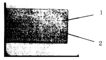
- FIG. 3 is a photograph showing the surface of the Co-based amorphous magnetic alloy ribbon 1 having streak-like marks 2 along the long axis.
- the streak-shaped marks 2A do not need to be straight along the major axis and may be moderately wavy, but are usually straight.
- the antenna magnetic core does not have to be constituted only by the Co-based amorphous magnetic alloy ribbon 1 having the streak-like marks 2A along the major axis, but the Co-based amorphous magnetic alloy constituting the laminated body. It is only necessary that 60% or more of the ribbons 1 have a streak-like mark 2A along the long axis. According to the antenna magnetic core made of such a laminate, it is possible to improve the characteristics with respect to signals in a low frequency band.
- the Co-based amorphous magnetic alloy ribbon 1 having the streak-like marks 2A along the long axis is more preferably 80% or more in terms of the number ratio. In particular, it is desirable that all of the Co-based amorphous magnetic alloy ribbons 1 (100% by number ratio) constituting the laminate have streak-like marks 2A along the major axis.
- a Co-based amorphous magnetic alloy ribbon 1 having a shape mark 2B can be used. Furthermore, it may be a Co-based amorphous magnetic alloy ribbon such as a magnetic alloy ribbon having streak-like marks formed in a direction other than the major axis direction or the minor axis direction, or a magnetic alloy ribbon having no clear stripe-like marks. What is necessary is just to be sufficient, and it is not limited to the formation direction of a stripe mark, or the presence or absence of a stripe mark.
- the Co-based amorphous magnetic alloy ribbon 1 located in the outermost layers (the lowermost layer and the uppermost layer) on both sides of the laminate preferably has a streak-like mark 2A along the long axis.
- the influence of the magnetic alloy ribbon located in the outermost layer (the lowermost layer and the uppermost layer) is large on the characteristics of the antenna magnetic core composed of a laminated body of magnetic alloy ribbons. For this reason, it is preferable that the Co-based amorphous magnetic alloy ribbon 1 located in the outermost layer has a streak-like mark 2A along the long axis.
- Examples of the streak-like trace 2 include a trace on the roll surface when the Co-based amorphous magnetic alloy ribbon 1 is produced by a roll quenching method.
- the Co-based amorphous magnetic alloy ribbon 1 is produced by a roll quenching method in which a molten metal is supplied onto a quenching roll rotated at a high speed and quenched.
- a roll quenching method a single roll method or a twin roll method is known, but since both quench rolls are used, traces of the roll surface remain in a streak shape in the obtained ribbon.
- streak-like marks are easily formed on the surface (free surface) opposite to the roll surface.
- 2 and 3 show streak-like marks 2 formed on the roll surface of the Co-based amorphous magnetic alloy ribbon 1.
- the size of the streak-like mark 2 is random, but usually has a contrast that can be recognized with the naked eye.
- the antenna is constructed by winding a coil of a Co-based amorphous magnetic alloy ribbon 1 on the antenna core.
- winding is performed along the long axis direction of the antenna core.
- the magnetic field generated by the current flowing through the winding is applied in the major axis direction of the antenna core.
- the characteristics of the antenna wound in the major axis direction of the antenna core Can be increased. This is presumably because the magnetic characteristics of the antenna core are improved by the fine magnetic domain structure of the Co-based amorphous magnetic alloy ribbon 1 against an external magnetic field.
- the Co-based amorphous magnetic alloy ribbon 1 is not particularly limited as long as the ratio (L1 / L2) of the major axis length (L1) to the minor axis length (L2) exceeds 1, but L1 / L2 When the ratio is less than 2, the effect of improving magnetic properties is small. When the L1 / L2 ratio exceeds 40, the shape of the antenna magnetic core becomes long, and the practicality for a small wristwatch or a keyless application is lowered. In addition, alignment during the lamination process becomes difficult, and handling properties are reduced. Considering improvement in magnetic properties and handling (manufacturability), the L1 / L2 ratio of the Co-based amorphous magnetic alloy ribbon 1 is preferably in the range of 2 to 40, more preferably in the range of 3 to 20. is there.
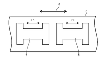
- the shape of the Co-based amorphous magnetic alloy ribbon 1 is not limited to the rectangle as shown in FIG. 1, but may be an H shape as shown in FIGS.
- An antenna magnetic core made of a laminated body of the Co-based amorphous magnetic alloy ribbon 1 having an H shape contributes to an improvement in communication characteristics of an antenna formed by winding a coil.
- the shape of the Co-based amorphous magnetic alloy ribbon 1 may have a corner having an R shape, for example, in order to improve the press-punching property in the H shape.
- the shape of the Co-based amorphous magnetic alloy ribbon 1 may be elliptical or polygonal. In any case, the length L1 in the major axis direction of the Co-based amorphous magnetic alloy ribbon 1 indicates the maximum width of the ribbon, and the length L2 in the minor axis direction indicates the minimum width of the ribbon.
- the number of laminated Co-based amorphous magnetic alloy ribbons 1 is not particularly limited, but is preferably in the range of 10 to 50.
- the average thickness of the Co-based amorphous magnetic alloy ribbon 1 thickness obtained from the size and mass of the ribbon and the density of the material
- sufficient magnetic properties L value
- the antenna magnetic core becomes too thick to cope with the reduction in thickness.
- t1 / t2 of the Co-based amorphous magnetic alloy ribbon 1 is 1 or more.
- the range is preferably 1.4 or less.
- the maximum thickness t1 of the Co-based amorphous magnetic alloy ribbon 1 indicates the maximum value when the thickness of the ribbon 1 is measured with a micrometer.
- the density ⁇ is determined by the Archimedes method. In the case of the Co-based amorphous magnetic alloy ribbon 1 having the streak-like marks 2, fine irregularities are generated on the surface.
- t1 / t2 of the Co-based amorphous magnetic alloy ribbon 1 is preferably 1.4 or less.
- t1 / t2 is more preferably in the range of 1.1 to 1.3.
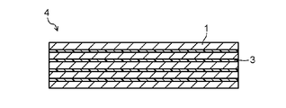
- the antenna core is formed by laminating a Co-based amorphous magnetic alloy ribbon 1. At this time, it is preferable to interpose an insulating resin layer at least partly between the Co-based amorphous magnetic alloy ribbons 1.
- FIG. 7 shows an antenna core 4 in which an insulating resin layer 3 is provided between the Co-based amorphous magnetic alloy ribbon 1.
- the insulating resin is not particularly limited as long as interlayer insulation can be obtained, but it is preferable to use a heat-welding resin such as an epoxy resin or a polyimide resin.
- An epoxy resin is suitable for heat welding at a temperature of 300 ° C. or less, and a polyimide resin is suitable for heat welding at a temperature higher than 300 ° C.
- Each thickness of the insulating resin layer 3 is preferably in the range of 1 to 5 ⁇ m. Further, T2 / T1 is preferably in the range of 0.1 to 0.4, where T1 is the thickness of the antenna core 4 and T2 is the total thickness of the insulating resin layer. If T2 / T1 is less than 0.1, the insulation may be insufficient. Further, if the insulating resin layer 3 is small, the adhesive strength is weak, and the strength of the laminated body (antenna core) may be reduced and may be scattered during the winding process. There is also a method of increasing the pressing force at the time of stacking in order to prevent separation, but if the pressing force is strong, the L value and Q value of the antenna magnetic core decrease.
- a maximum magnetic flux density of 0.35 to 1.2 T (Tesla) can be obtained.
- the heat treatment may be performed on the Co-based amorphous magnetic alloy ribbon 1 before forming the laminated body or may be performed on the laminated body. Further, the Co-based amorphous magnetic alloy ribbon 1 may be subjected to bending processing or the like as necessary.
- the antenna core of this embodiment is not particularly limited to the manufacturing method as long as it has the above-described configuration.
- Examples of a method for manufacturing the antenna magnetic core of this embodiment with a high yield include the following manufacturing methods.
- the manufacturing method of the antenna core according to the first embodiment includes a step of producing a long magnetic alloy ribbon by a roll quenching method, and the length direction of the long magnetic alloy ribbon is on the long axis side. Cutting or pressing a long magnetic alloy ribbon to produce a plurality of magnetic alloy ribbons in which the ratio of the length of the long axis to the length of the short axis exceeds 1, and the plurality of magnetic alloy ribbons A step of forming a laminated body and a step of impregnating an insulating resin between the magnetic alloy ribbons in the laminated body.
- raw material powder such as Co is mixed so as to have a predetermined alloy composition, and then melted to obtain a molten alloy.
- the molten alloy is injected into a cooling roll that rotates at a high speed, and the molten alloy is rapidly cooled at a speed of about 10 4 to 10 6 ° C./second to obtain a long Co-based amorphous magnetic alloy ribbon (original material).
- the length of the magnetic alloy ribbon (original material) is arbitrary, but is preferably in the range of 2 to 15 km in view of mass productivity. When the length is less than 2 km, the amount of ribbon obtained at one time is small, and is not suitable for mass production. On the other hand, if the length exceeds 15 km, the labor for winding onto the spool and the spool after winding become too heavy, and the workability deteriorates. Furthermore, in order to inject a magnetic alloy ribbon of 15 km or more, a roll having high heat resistance is required. The thickness and width of the magnetic alloy ribbon (original material) are adjusted by the shape of the nozzle and the injection pressure when the molten alloy is injected.
- the roll quenching method includes the single roll method and the twin roll method. In either case, streak-like marks are formed on the roll surface of the obtained magnetic alloy ribbon. In the case of the single roll method excellent in mass productivity, streak-like marks are easily formed on the surface (free surface) opposite to the roll surface. The streak can be confirmed with the naked eye.
- the streak-like traces are those in which traces of a minute air layer caught between the molten alloy and the roll are randomly reflected.
- the shape of the streak is also random, but is generally formed in a substantially linear shape along the length direction of the magnetic alloy ribbon, that is, the rotation direction of the roll. In addition, the shape of the streak-like traces on the roll surface and the free-form streak need not be the same.
- the obtained long magnetic alloy ribbon (original material) is wound on a spool.
- a plurality of magnetic alloy ribbons constituting the laminate are produced by cutting or pressing while supplying the magnetic alloy ribbons (original materials) from the spool by a predetermined amount.
- the length direction (indicated by the arrow X in the figure) of the long magnetic alloy ribbon (original material) 5 is the long axis (L1) side of the magnetic alloy ribbon 1.
- the long magnetic alloy ribbon (original material) 5 is cut or pressed, and the ratio (L1 / L2) of the length (L1) of the long axis to the length (L2) of the short axis is 1.
- An excess magnetic alloy ribbon 1 is prepared. Cutting or pressing may be performed according to the L1 / L2 ratio of the target antenna magnetic core, and the following method can be cited as a method for improving mass productivity.
- a long and narrow magnetic alloy ribbon is completed.
- a long and narrow magnetic alloy ribbon is cut or pressed according to the length of the long axis to obtain a magnetic alloy ribbon having a desired shape. For example, in the case of a 10 ⁇ 3 mm rectangular magnetic core, if the original width of a long magnetic alloy ribbon is 50 mm, this is once slit into a 3 mm width and then cut to a length of 10 mm. If a plurality of narrow magnetic alloy ribbons are stacked and then cut, a magnetic alloy ribbon can be obtained more efficiently.
- Insulating resin is infiltrated between the layers of the laminated body to manufacture a target antenna magnetic core.
- a method of infiltrating the insulating resin between the layers of the laminate a method of immersing the laminate in a bath of insulating resin, a method of applying the insulating resin or its precursor to the side surface of the laminate, or the like can be applied.
- the insulating resin it is preferable to use a heat-welding resin such as an epoxy resin or a polyimide resin.
- heat-welding resin If it is a heat-welding resin, it can be immersed in a bath of insulating resin, or after applying the insulating resin or its precursor to the side surface of the laminate, it is subjected to curing treatment (heat treatment or drying treatment) at a predetermined temperature.
- the insulating resin enters the interlayer and functions as an insulating layer.
- the heat treatment temperature for the curing treatment is approximately 180 to 300 ° C., although it depends on the material of the resin used. For example, in the case of an epoxy resin, heat treatment is preferably performed at a temperature of 180 to 220 ° C. for 1 to 3 hours.
- the laminate in which the insulating resin layer is interposed between layers has a structure in which a plurality of magnetic alloy ribbons are integrated, and the characteristics and handleability of the antenna core are improved.
- the thickness of the insulating resin layer is preferably in the range of 1 to 5 ⁇ m.
- the method of manufacturing an antenna core according to the second embodiment includes a step of producing a long magnetic alloy ribbon by a roll quenching method, and a step of coating at least one surface of the long magnetic alloy ribbon with an insulating resin.
- the long magnetic alloy ribbon is cut or pressed so that the length direction of the long magnetic alloy ribbon is on the long axis side, and the ratio of the length of the long axis to the length of the short axis is A step of producing a plurality of magnetic alloy ribbons exceeding 1, and a step of laminating the plurality of magnetic alloy ribbons to form a laminate.
- the process of producing a long magnetic alloy ribbon by the roll quenching method is the same as the manufacturing method according to the first embodiment.
- the insulating resin used is the same as in the first embodiment.
- the covering step with the insulating resin is carried out by feeding a long magnetic alloy ribbon from the spool and immersing it in a bath of insulating resin or applying the insulating resin by spraying. Moreover, when feeding a long magnetic alloy ribbon from a spool, a method of applying an insulating resin may be applied.
- the long magnetic alloy ribbon coated with the insulating resin is cut or pressed so that the length direction is on the long axis side, and the length of the long axis (L1) with respect to the length of the short axis (L2) ) Ratio (L1 / L2) exceeding 1 is produced.
- L1 long axis
- L2 long axis
- Ratio (L1 / L2) exceeding 1 is produced.
- mass productivity is achieved. Will improve.
- the desired antenna magnetic core is manufactured by laminating a predetermined number of the obtained magnetic alloy ribbons with an insulating resin and then heat-treating and drying.
- the first manufacturing method and the second manufacturing method are selectively used, for example, when the number of stacked layers is 20 or more and when the number of stacked layers is large, or when the minor axis length (L2) is 3 mm or more, the minor axis width is wide. In some cases, it is preferable to use the second production method.
- the second manufacturing method since the insulating resin is applied before the lamination, even if the number of laminated layers is large or the minor axis width is wide, the insulating layer can be formed properly between the layers, and this functions as an adhesive layer. Therefore, the strength of the antenna magnetic core is stabilized.
- the antenna core may be heat-treated or bent if necessary.
- the heat treatment to the antenna magnetic core is performed separately from the heat treatment for curing the insulating resin, and is performed to improve the magnetic characteristics.
- the heat treatment conditions are preferably 120 to 320 ° C. ⁇ 0.5 to 3 hours.
- you may heat-process in the magnetic field of 160 A / m or more as needed, Preferably in the magnetic field of 800 A / m or more.
- the heat treatment for improving the magnetic properties may be performed on the magnetic alloy ribbon before lamination.
- the bending process may be performed before laminating the magnetic alloy ribbon, or may be performed after the antenna magnetic core is formed.
- the bending process is effective when the antenna is mounted on a detection system or the like when the mounting space is small and the antenna needs to be bent. Since the Co-based amorphous magnetic alloy ribbon has high strength, it will not be damaged even if it is folded, for example, in two. For this reason, it is easy to cope with a shape change caused by a bending process, so that an antenna can be mounted in a curved mounting space.
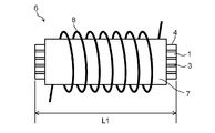
- the antenna according to the embodiment of the present invention is configured by winding the antenna along the long axis of the antenna core according to the above-described embodiment.
- the antenna 6 includes an antenna magnetic core 4 made of a laminate of a Co-based amorphous magnetic alloy ribbon 1 and a winding 8 wound around an insulating member 7 around the antenna core 4. .
- the winding 8 is wound along the long axis of the antenna magnetic core 4.
- the number of windings depends on the required magnetic characteristics and dimensions, but is preferably 800 to 1500 turns, for example.
- the portion of the antenna core 4 where the winding process is performed is covered with an insulating member 7 as necessary.
- the insulating member 7 include a resin coating, a resin film, an adhesive tape, a resin mold, and a resin bobbin.
- the insulating member 7 may be disposed so as to cover the entire antenna magnetic core 4, but in this embodiment, since the corrosion-resistant Co-based amorphous magnetic alloy ribbon 1 is used, only the portion subjected to the winding process is insulated. Even if the structure is covered with the member 7, the generation of rust and the like can be suppressed. A part of the Co-based amorphous magnetic alloy ribbon 1 may be exposed.
- the antenna 6 of this embodiment is suitably used for a detection system, for example.
- a detection system receives a radio signal from a transmitter that transmits a specific radio signal such as a radio signal having a unique ID as its content, and detects that the transmitter is specific.
- a receiver receives a radio signal from a transmitter that transmits a specific radio signal such as a radio signal having a unique ID as its content, and detects that the transmitter is specific.
- a receiver can be applied to both the transmitting antenna of the transmitter and the receiving antenna of the receiver, but is particularly suitable for the receiving antenna.
- the receiver and the transmitter are constituted by card parts, for example.
- the receiving antenna and the transmitting antenna are arranged in the card component and are resin-sealed together with other components.
- the antenna 6 Since the antenna 6 is excellent in communication sensitivity in the frequency band of 40 to 150 kHz, it is suitable for a detection system using a radio signal having a frequency in the range of 40 to 150 kHz. In particular, the antenna 6 exhibits good communication characteristics in a frequency band of 120 to 130 kHz. Further, since the antenna core 4 constituting the antenna 6 is not brittle like a ferrite core or easily rusted like an antenna core using a Fe-based amorphous alloy ribbon, the antenna 6 is used in a stressed usage environment or moisture. It is suitable for a detection stem used in an environment where there are many cases.
- the antenna 7 is not limited to the reception antenna of the receiver in the detection system, but can be applied to, for example, a reception antenna of a radio timepiece, particularly a reception antenna of a radio wave wristwatch that is required to be downsized.
- the detection system of this embodiment includes an automobile detection system, an RFID tag system used for management of various articles, entrance / exit management, and the like.
- a detection system for automobiles a keyless entry system for automobiles (or called a smart entry system) can be cited.
- the keyless entry system is a system in which a receiver is mounted on a handle, a tire, a door, etc., and a switch is turned on and off by a portable transmitter. This makes it possible to lock the handle, lock the tire, turn the door lock on and off, etc. without inserting the key into the cylinder.
- TPMS tire pressure monitoring system
- the metal body interferes with communication when the frequency of radio signals increases. For this reason, a signal in a relatively low frequency band of about 40 to 150 kHz is used. Since the antenna of this embodiment has excellent communication characteristics in the frequency band of 40 to 150 kHz, particularly in the frequency band of 120 to 130 kHz, it is suitable for a detection system in which radio signals in this frequency band are used.
- the automotive use was demonstrated as a keyless entry system, besides this, it is applicable also to the detection system for crime preventions, such as the opening / closing management of the motorcycle which uses the signal of the same frequency band, a bicycle, and a building.
- a slit of 4 mm, 1.2 mm, and 0.8 mm in width was put in the obtained long magnetic alloy ribbon, and a long magnetic alloy ribbon hoop material of each width was produced.
- a hoop material was obtained.
- a hoop material having a width (major axis) of 4 mm was cut into lengths (major axes) of 12 mm (Example 1), 7.5 mm (Example 2), and 15 mm (Example 3).
- Each of the obtained magnetic alloy ribbons has streak-like marks along the long axis. Then, after laminating 20 pieces of the magnetic alloy ribbons of each length, the antenna cores of Examples 1 to 3 were obtained by performing a curing heat treatment under the conditions of 200 ° C. ⁇ 2 h.
- the hoop material having a width of 1.2 mm was cut to a length of 20 mm. After 20 such magnetic alloy ribbons were laminated, a curing heat treatment was performed under the conditions of 200 ° C. ⁇ 2 h to obtain the antenna core of Example 4. A hoop material having a width of 0.8 mm was cut to a length of 29 mm. After stacking 20 such magnetic alloy ribbons, the antenna core of Example 5 was obtained by performing a curing heat treatment under the conditions of 200 ° C. ⁇ 2 h.
- Example 1 A magnetic alloy ribbon with an insulating resin layer was prepared in the same manner as in Example 1 except that the streak-shaped marks formed on the surface of the Co-based amorphous magnetic alloy ribbon were cut in the short axis direction. This is obtained by slitting a long magnetic alloy ribbon similar to Example 1 with a width of 12 mm and then cutting it into a length of 4 mm. After 20 magnetic alloy ribbons were laminated, a curing heat treatment was performed under the conditions of 200 ° C. ⁇ 2 h to produce an antenna core.
- the maximum magnetic flux density was measured for each of the antenna cores of Examples 1 to 5 and Comparative Example 1 described above.
- the maximum magnetic flux density was measured by using a magnetic core having a closed magnetic circuit structure in which the above-mentioned material was formed into a toroidal shape (outer diameter 12 mm ⁇ inner diameter 8 mm) and processed under the same curing conditions.
- the applied magnetic field (direct current) was 800 A / m. The measurement results are shown in Table 1.
- an insulating bobbin provided with a cage for containing the antenna magnetic cores of Examples 1 to 5 and Comparative Example 1 was prepared.
- a 5 ⁇ 0.6 mm square through hole (inner cylinder) is provided inside the insulating bobbin.
- 700 turns of the insulation coated conductor 2UEW (diameter 0.1 mm) was wound to a width of 7.4 mm from the center of the insulation bobbin.
- Antennas were produced by inserting the antenna cores of Examples 1 to 5 and Comparative Example 1 into a bobbin and placing them in the center. As the characteristics of these antennas, L value and Q value were measured.
- L value and Q value using LCR meter 4192A (trade name) manufactured by Agilent Technologies.
- the frequency was 60 kHz and 100 kHz
- the set voltage was 0.1 V
- the measurement was performed in the short mode.
- the results are shown in Table 2.
- L value and Q value (100 kHz) at the time of air core of this insulating coil were 936 ⁇ H and 18.9.
- the measurement was performed by inserting a magnetic core after performing a short zero of the LCR meter in an air-core state.
- Example 6 A long magnetic alloy ribbon (original material) similar to that in Example 1 was used, and this was pressed into the H shape shown in FIG.
- the length of the major axis (L1) is 16 mm
- the length of the minor axis (L2) that is, the width of the central winding portion is 0.76 mm
- the length of that portion is 10.2 mm
- the width of the H-shaped ridge is 2 .9 mm. Processing was performed so that the long axis direction of the H shape was parallel to the direction of the streak-like marks formed on the magnetic alloy ribbon.
- lamination and resin curing were performed in the same manner as in Example 1 to produce an antenna core.
- an insulating adhesive tape width 10 mm, thickness 25 ⁇ m
- an insulation coated conductor having a diameter of 0.06 mm was wound for 1400 turns. In this way, an antenna in which an H-shaped antenna magnetic core was wound was manufactured.
- Example 7 Co 79.25 Fe 4.95 Ni 3.55 Nb 2.85 Si 6.1 B 3.3
- a magnetic alloy ribbon made of a Co-based amorphous alloy having a composition of 3.3 was produced by a single roll method, and this was used.
- an antenna having an H-shaped antenna magnetic core was produced.
- Example 6 (Comparative Example 2) Example 6 except that the H-shaped punching direction of the long magnetic alloy ribbon is shifted by 90 degrees and the short axis direction of the H-shape and the streaky traces of the magnetic alloy ribbon are parallel to each other. Similarly, an antenna having an H-shaped antenna magnetic core was produced.
- Comparative Example 4 An antenna was fabricated in the same manner as in Comparative Example 2 except that the magnetic alloy ribbon used as the base material was made of Metaglass 2605SA1 which is an Fe-based amorphous.
- Example 8 to 11 An antenna core was manufactured in the same manner as in Example 6 except that the heat treatment shown in Table 4 was performed on the antenna core manufactured in Example 6. Their maximum magnetic flux density was determined. Next, each antenna magnetic core was subjected to the same winding process as in Example 6 to produce an antenna. The L value and Q value at 40 kHz / 0.1 V of these antennas were measured. Furthermore, it was confirmed whether or not each of the magnetic alloy thin ribbons in each example was cracked when it was bent at 180 degrees so as to have a crease with almost no gap. The results are shown in Table 4.
- the characteristics can be improved by selecting the heat treatment conditions. However, at a temperature of 400 ° C. or higher, it is easily cracked because it approaches the crystallization temperature. For this reason, there is a possibility that the manufacturing yield of the antenna core is adversely affected and cracking may occur during a strong impact.
- the heat treatment temperature is preferably 300 ° C. or lower.
- the antenna core is preferably heat-treated at a temperature of 300 ° C. or lower when it is bent or used in an environment with large vibrations.
- Example 12 to 13 An antenna was manufactured in the same manner as in Example 6 except that the winding number condition in Example 6 was changed to the conditions shown in Table 5. The L value and Q value at 40 kHz / 0.1 V of these antennas were measured. Table 5 shows the measurement results. As is apparent from Table 5, the antenna characteristics can be adjusted according to the winding conditions for the antenna core.
- Example 14 Using the antenna core produced in Example 1, an insulating tape having a thickness of 25 ⁇ m was wound around the antenna core, and then an insulating coated conductor having a diameter of 0.045 mm was wound around the center of the long axis for 600 turns. The L value and Q value at 134.2 kHz / 0.1 V of the antenna thus obtained were measured. Furthermore, a chip capacitor was connected in parallel with this to produce an LC antenna component. The capacitance of the capacitor was set to 320 pF so as to be synchronized with the frequency of the keyless system (134.2 kHz).
- Example 5 The antenna core in the smart key of Example 14 was changed to a ferrite core, and the number of turns was adjusted so that the L value specification matched that of Example 14.
- the communication characteristics (before and after impact) of this smart key were measured in the same manner as in Example 14. Table 6 shows the measurement results.
- the antenna magnetic core according to the example is resistant to impact, so that the impact resistance of the smart key using the antenna core can be improved. Therefore, it is possible to provide a keyless entry system with excellent reliability.
- Example 15 to 20 In the antenna core of Example 1, an antenna core was manufactured in the same manner as in Example 1 except that the type and number of magnetic alloy ribbons constituting the laminate were changed to the conditions shown in Table 7. The number of laminated magnetic alloy ribbons was 20 in all cases. Further, the maximum thickness t1 and the average thickness t2 of the magnetic alloy ribbon were measured to obtain t1 / t2. The results are shown in Table 7.
- the antenna cores of Examples 15 to 17 are obtained by randomly laminating a magnetic alloy ribbon having a streak-like trace along the major axis and a magnetic alloy ribbon having a stripe-like trace along the minor axis.
- the magnetic alloy ribbon having the streak-like traces along the short axis was arranged in the center, and the magnetic alloy ribbon having the stripe-like traces along the major axis was arranged on both sides thereof. Is.
- L and Q values at 60 kHz and 100 kHz were measured. Table 8 shows the measurement results.
- the antenna magnetic core according to the aspect of the present invention is effectively used for an antenna that performs communication in a relatively low frequency band.
- the antenna according to the aspect of the present invention is effectively used as a receiving antenna of a receiver or a receiving antenna of a radio clock in a detection system.
- the detection system of the present invention is effective for detection systems for automobiles and various crime prevention.
- SYMBOLS 1 Co-based amorphous magnetic alloy ribbon, 2, 2A, 2B ... Strip mark, 3 ... Insulating resin layer, 4 ... Antenna core, 5 ... Long Co-based amorphous magnetic alloy ribbon (original material), 6 ... Antenna, 7 ... insulating member, 8 ... winding.
Abstract
Description
一般式:CoaDbMcSidBe …(1)
(式中、DはFe及びNiから選ばれる少なくとも1種の元素、MはTi、V、Cr、Mn、Cu、Zr、Nb、Mo、Ta、及びWから選ばれる少なくとも1種の元素を示し、a、b、c、d、及びeはa+b+c+d+e=100原子%、1≦b≦10、0.3≦c≦6、5≦d≦12、1≦e≦8である) The Co-based amorphous
General formula: Co a D b M c Si d B e ... (1)
(Wherein D represents at least one element selected from Fe and Ni, and M represents at least one element selected from Ti, V, Cr, Mn, Cu, Zr, Nb, Mo, Ta, and W) A, b, c, d, and e are a + b + c + d + e = 100 atomic%, 1 ≦ b ≦ 10, 0.3 ≦ c ≦ 6, 5 ≦ d ≦ 12, and 1 ≦ e ≦ 8)
Co80.95Fe3.95Nb2.8Cr2.0Si7.9B2.4組成のCo基アモルファス合金からなる長尺の磁性合金薄帯(元材)を、単ロール法により作製した。長尺の磁性合金薄帯(元材)の長さは7500m、幅は33mm、平均厚さは20μmである。長尺の磁性合金薄帯のロール面及びフリー面には、長さ方向(ロールの回転方向)に沿ってスジ状痕が形成されていた。スジ状痕は目視により確認可能であった。 (Examples 1 to 5)
Co 80.95 Fe 3.95 Nb 2.8 Cr 2.0 Si 7.9 B A long magnetic alloy ribbon (original material) made of a Co-based amorphous alloy having a composition of 2.4 was produced by a single roll method. did. The length of the long magnetic alloy ribbon (original material) is 7500 m, the width is 33 mm, and the average thickness is 20 μm. On the roll surface and the free surface of the long magnetic alloy ribbon, streak-like marks were formed along the length direction (the rotation direction of the roll). The streak-like marks could be confirmed visually.
Co基アモルファス磁性合金薄帯の表面に形成されたスジ状痕が短軸方向となるように切断した以外は、実施例1と同様な絶縁樹脂層付き磁性合金薄帯を用意した。これは、実施例1と同様な長尺の磁性合金薄帯を幅12mmでスリットした後、4mmの長さに切断して得たものである。この磁性合金薄帯を20枚積層した後、200℃×2hの条件で硬化熱処理を施してアンテナ磁心を作製した。 (Comparative Example 1)
A magnetic alloy ribbon with an insulating resin layer was prepared in the same manner as in Example 1 except that the streak-shaped marks formed on the surface of the Co-based amorphous magnetic alloy ribbon were cut in the short axis direction. This is obtained by slitting a long magnetic alloy ribbon similar to Example 1 with a width of 12 mm and then cutting it into a length of 4 mm. After 20 magnetic alloy ribbons were laminated, a curing heat treatment was performed under the conditions of 200 ° C. × 2 h to produce an antenna core.


実施例1と同様な長尺の磁性合金薄帯(元材)を使用し、これを図5に示したH形状にプレス加工した。長軸の長さ(L1)は16mm、短軸の長さ(L2)、つまり中央巻線部の幅は0.76mm、その部分の長さは10.2mm、H形状の鍔の幅は2.9mmとした。H形状の長軸方向と磁性合金薄帯に形成されたスジ状痕の方向とが平行となるように加工した。このH形状の磁性合金薄帯を用いて、実施例1と同様に積層及び樹脂硬化処理を行ってアンテナ磁心を作製した。 (Example 6)
A long magnetic alloy ribbon (original material) similar to that in Example 1 was used, and this was pressed into the H shape shown in FIG. The length of the major axis (L1) is 16 mm, the length of the minor axis (L2), that is, the width of the central winding portion is 0.76 mm, the length of that portion is 10.2 mm, and the width of the H-shaped ridge is 2 .9 mm. Processing was performed so that the long axis direction of the H shape was parallel to the direction of the streak-like marks formed on the magnetic alloy ribbon. Using this H-shaped magnetic alloy ribbon, lamination and resin curing were performed in the same manner as in Example 1 to produce an antenna core.
Co79.25Fe4.95Ni3.55Nb2.85Si6.1B3.3組成のCo基アモルファス合金からなる磁性合金薄帯を単ロール法で作製し、これを使用する以外は実施例6と同様にして、H形状のアンテナ磁心を有するアンテナを作製した。 (Example 7)
Co 79.25 Fe 4.95 Ni 3.55 Nb 2.85 Si 6.1 B 3.3 A magnetic alloy ribbon made of a Co-based amorphous alloy having a composition of 3.3 was produced by a single roll method, and this was used. In the same manner as in Example 6, an antenna having an H-shaped antenna magnetic core was produced.
長尺の磁性合金薄帯のH形状のプレス抜き方向を90度ずらし、H形状の短軸方向と磁性合金薄帯のスジ状痕とが平行となるように加工する以外は、実施例6と同様にしてH形状のアンテナ磁心を有するアンテナを作製した。 (Comparative Example 2)
Example 6 except that the H-shaped punching direction of the long magnetic alloy ribbon is shifted by 90 degrees and the short axis direction of the H-shape and the streaky traces of the magnetic alloy ribbon are parallel to each other. Similarly, an antenna having an H-shaped antenna magnetic core was produced.
長尺の磁性合金薄帯を実施例7と同組成の磁性合金薄帯とする以外は、比較例2と同様にしてH形状のアンテナ磁心を有するアンテナを作製した。 (Comparative Example 3)
An antenna having an H-shaped antenna core was produced in the same manner as in Comparative Example 2 except that the long magnetic alloy ribbon was a magnetic alloy ribbon having the same composition as in Example 7.
元材となる磁性合金薄帯をFe系アモルファスであるMetaglass社製2605SA1とする以外は、比較例2と同様にしてアンテナを作製した。 (Comparative Example 4)
An antenna was fabricated in the same manner as in Comparative Example 2 except that the magnetic alloy ribbon used as the base material was made of Metaglass 2605SA1 which is an Fe-based amorphous.

実施例6で作製したアンテナ磁心に対して表4に示す熱処理を施す以外は、それぞれ実施例6と同様にしてアンテナ磁心を作製した。それらの最大磁束密度を求めた。次に、各アンテナ磁心に実施例6と同様の巻線処理を施してアンテナを作製した。これらアンテナの40kHz/0.1VにおけるL値及びQ値を測定した。さらに、各例の磁性合金薄帯1枚を180度にほぼ隙間なく折り目が付くように折り曲げた際に、割れるかどうか確認した。それらの結果を表4に示す。 (Examples 8 to 11)
An antenna core was manufactured in the same manner as in Example 6 except that the heat treatment shown in Table 4 was performed on the antenna core manufactured in Example 6. Their maximum magnetic flux density was determined. Next, each antenna magnetic core was subjected to the same winding process as in Example 6 to produce an antenna. The L value and Q value at 40 kHz / 0.1 V of these antennas were measured. Furthermore, it was confirmed whether or not each of the magnetic alloy thin ribbons in each example was cracked when it was bent at 180 degrees so as to have a crease with almost no gap. The results are shown in Table 4.

実施例6の巻数条件を表5に示す条件に変更する以外は、実施例6と同様にしてアンテナを作製した。これらアンテナの40kHz/0.1VにおけるL値及びQ値を測定した。測定結果を表5に示す。表5から明らかなように、アンテナ磁心に対する巻線条件によりアンテナの特性を調整することができる。 (Examples 12 to 13)
An antenna was manufactured in the same manner as in Example 6 except that the winding number condition in Example 6 was changed to the conditions shown in Table 5. The L value and Q value at 40 kHz / 0.1 V of these antennas were measured. Table 5 shows the measurement results. As is apparent from Table 5, the antenna characteristics can be adjusted according to the winding conditions for the antenna core.

実施例1で作製したアンテナ磁心を用いて、これに厚さ25μmの絶縁テープを1周巻いた後、長軸の中央付近に直径0.045mmの絶縁被覆導線を600ターン巻回した。このようにして得たアンテナの134.2kHz/0.1VにおけるL値及びQ値を測定した。さらに、これと並列にチップコンデンサを接続してLCアンテナ部品を作製した。なお、コンデンサの容量はキーレスシステムの周波数(134.2kHz)と同調するように320pFに設定した。 (Example 14)
Using the antenna core produced in Example 1, an insulating tape having a thickness of 25 μm was wound around the antenna core, and then an insulating coated conductor having a diameter of 0.045 mm was wound around the center of the long axis for 600 turns. The L value and Q value at 134.2 kHz / 0.1 V of the antenna thus obtained were measured. Furthermore, a chip capacitor was connected in parallel with this to produce an LC antenna component. The capacitance of the capacitor was set to 320 pF so as to be synchronized with the frequency of the keyless system (134.2 kHz).
実施例14のスマートキーにおけるアンテナ磁心をフェライトコアに変更し、L値の仕様が実施例14と合うように巻数を調整したものを用意した。このスマートキーの通信特性(衝撃前と衝撃後)を実施例14と同様にして測定した。測定結果を表6に示す。 (Comparative Example 5)
The antenna core in the smart key of Example 14 was changed to a ferrite core, and the number of turns was adjusted so that the L value specification matched that of Example 14. The communication characteristics (before and after impact) of this smart key were measured in the same manner as in Example 14. Table 6 shows the measurement results.

実施例1のアンテナ磁心において、積層体を構成する磁性合金薄帯の種類と枚数を表7に示す条件に変更する以外は、実施例1と同様にしてアンテナ磁心を作製した。磁性合金薄帯の積層枚数はいずれも20枚とした。また、磁性合金薄帯の最大厚さt1と平均厚さt2とを測定してt1/t2を求めた。その結果を表7に示す。 (Examples 15 to 20)
In the antenna core of Example 1, an antenna core was manufactured in the same manner as in Example 1 except that the type and number of magnetic alloy ribbons constituting the laminate were changed to the conditions shown in Table 7. The number of laminated magnetic alloy ribbons was 20 in all cases. Further, the maximum thickness t1 and the average thickness t2 of the magnetic alloy ribbon were measured to obtain t1 / t2. The results are shown in Table 7.


Claims (22)
- 短軸の長さに対する長軸の長さの比が1を超える複数のCo基アモルファス磁性合金薄帯の積層体を具備するアンテナ磁心であって、
前記複数のCo基アモルファス磁性合金薄帯のうちの枚数比率で60%以上の前記Co基アモルファス磁性合金薄帯は、少なくとも一方の表面に前記長軸に沿って形成されたスジ状痕を有することを特徴とするアンテナ磁心。 An antenna magnetic core comprising a laminate of a plurality of Co-based amorphous magnetic alloy ribbons in which the ratio of the length of the long axis to the length of the short axis exceeds 1,
The Co-based amorphous magnetic alloy ribbon of 60% or more in the number ratio among the plurality of Co-based amorphous magnetic alloy ribbons has streak-like marks formed along the major axis on at least one surface. Antenna core characterized by. - 請求項1記載のアンテナ磁心において、
前記複数のCo基アモルファス磁性合金薄帯のうち、前記積層体の両側の最外層に位置する前記Co基アモルファス磁性合金薄帯は、前記スジ状痕を有することを特徴とするアンテナ磁心。 The antenna magnetic core according to claim 1, wherein
Of the plurality of Co-based amorphous magnetic alloy ribbons, the Co-based amorphous magnetic alloy ribbon located in the outermost layer on both sides of the laminated body has the streak-like marks. - 請求項1記載のアンテナ磁心において、
前記Co基アモルファス磁性合金薄帯の前記短軸の長さに対する前記長軸の長さの比は2以上40以下の範囲であることを特徴とするアンテナ磁心。 The antenna magnetic core according to claim 1, wherein
The antenna core according to claim 1, wherein the ratio of the length of the major axis to the length of the minor axis of the Co-based amorphous magnetic alloy ribbon is in the range of 2 to 40. - 請求項1記載のアンテナ磁心において、
前記Co基アモルファス磁性合金薄帯の最大厚さをt1、前記Co基アモルファス磁性合金薄帯の平均厚さをt2としたとき、前記Co基アモルファス磁性合金薄帯のt1/t2は1以上1.4以下の範囲であることを特徴とするアンテナ磁心。 The antenna magnetic core according to claim 1, wherein
When the maximum thickness of the Co-based amorphous magnetic alloy ribbon is t1, and the average thickness of the Co-based amorphous magnetic alloy ribbon is t2, t1 / t2 of the Co-based amorphous magnetic alloy ribbon is 1 or more and 1. An antenna magnetic core having a range of 4 or less. - 請求項1記載のアンテナ磁心において、
前記Co基アモルファス磁性合金薄帯はH形状を有することを特徴とするアンテナ磁心。 The antenna magnetic core according to claim 1, wherein
The antenna core according to claim 1, wherein the Co-based amorphous magnetic alloy ribbon has an H shape. - 請求項1記載のアンテナ磁心において、
前記Co基アモルファス磁性合金薄帯は、
一般式:CoaDbMcSidBe
(式中、DはFe及びNiから選ばれる少なくとも1種の元素、MはTi、V、Cr、Mn、Cu、Zr、Nb、Mo、Ta、及びWから選ばれる少なくとも1種の元素を示し、a、b、c、d、及びeはa+b+c+d+e=100原子%、1≦b≦10、0.3≦c≦6、5≦d≦12、1≦e≦8である)
で表される組成を有することを特徴とするアンテナ磁心。 The antenna magnetic core according to claim 1, wherein
The Co-based amorphous magnetic alloy ribbon is
General formula: Co a D b M c Si d B e
(Wherein D represents at least one element selected from Fe and Ni, and M represents at least one element selected from Ti, V, Cr, Mn, Cu, Zr, Nb, Mo, Ta, and W) A, b, c, d, and e are a + b + c + d + e = 100 atomic%, 1 ≦ b ≦ 10, 0.3 ≦ c ≦ 6, 5 ≦ d ≦ 12, and 1 ≦ e ≦ 8)
An antenna magnetic core having a composition represented by: - 請求項1記載のアンテナ磁心において、
前記スジ状痕は前記Co基アモルファス磁性合金薄帯をロール急冷法により作製する際のロール面の痕であることを特徴とするアンテナ磁心。 The antenna magnetic core according to claim 1, wherein
The antenna core according to claim 1, wherein the streak marks are marks on a roll surface when the Co-based amorphous magnetic alloy ribbon is produced by a roll quenching method. - 請求項1記載のアンテナ磁心において、
前記Co基アモルファス磁性合金薄帯の積層枚数が10枚以上50枚以下の範囲であることを特徴とするアンテナ磁心。 The antenna magnetic core according to claim 1, wherein
An antenna magnetic core characterized in that the number of laminated Co-based amorphous magnetic alloy ribbons is in the range of 10 to 50. - 請求項1記載のアンテナ磁心において、
前記積層体は前記Co基アモルファス磁性合金薄帯間の少なくとも一部に介在された絶縁樹脂層を有することを特徴とするアンテナ磁心。 The antenna magnetic core according to claim 1, wherein
The antenna core according to claim 1, wherein the laminated body has an insulating resin layer interposed at least partly between the Co-based amorphous magnetic alloy ribbons. - 請求項1記載のアンテナ磁心において、
最大磁束密度が0.35T以上1.2T以下の範囲であることを特徴とするアンテナ磁心。 The antenna magnetic core according to claim 1, wherein
An antenna core having a maximum magnetic flux density in a range of 0.35T to 1.2T. - ロール急冷法により長尺のCo基アモルファス磁性合金薄帯を作製する工程と、
前記長尺のCo基アモルファス磁性合金薄帯の長さ方向が長軸側となるように、前記長尺のCo基アモルファス磁性合金薄帯を切断又はプレス加工して、短軸の長さに対する長軸の長さの比が1を超える複数のCo基アモルファス磁性合金薄帯を作製する工程と、
前記複数のCo基アモルファス磁性合金薄帯を積層して積層体を形成する工程と、
前記積層体における前記Co基アモルファス磁性合金薄帯の間に絶縁樹脂を浸透させる工程と
を具備することを特徴とするアンテナ磁心の製造方法。 Producing a long Co-based amorphous magnetic alloy ribbon by roll quenching;
The long Co-based amorphous magnetic alloy ribbon is cut or pressed so that the length direction of the long Co-based amorphous magnetic alloy ribbon is on the long axis side. Producing a plurality of Co-based amorphous magnetic alloy ribbons having a ratio of shaft lengths exceeding 1,
Laminating the plurality of Co-based amorphous magnetic alloy ribbons to form a laminate;
And a step of infiltrating an insulating resin between the Co-based amorphous magnetic alloy ribbons in the laminate. - 請求項11記載のアンテナ磁心の製造方法において、
前記絶縁樹脂を浸透させた前記積層体を熱処理する工程を具備することを特徴とするアンテナ磁心の製造方法。 In the manufacturing method of the antenna magnetic core according to claim 11,
A method of manufacturing an antenna magnetic core comprising a step of heat-treating the laminated body infiltrated with the insulating resin. - 請求項11記載のアンテナ磁心の製造方法において、
前記Co基アモルファス磁性合金薄帯は、少なくとも一方の表面に前記長軸に沿って形成されたスジ状痕を有することを特徴とするアンテナ磁心の製造方法。 In the manufacturing method of the antenna magnetic core according to claim 11,
The method of manufacturing an antenna magnetic core, wherein the Co-based amorphous magnetic alloy ribbon has streak-like marks formed along the major axis on at least one surface. - ロール急冷法により長尺のCo基アモルファス磁性合金薄帯を作製する工程と、
前記長尺のCo基アモルファス磁性合金薄帯の少なくとも一方の表面に絶縁樹脂を被覆する工程と、
前記長尺のCo基アモルファス磁性合金薄帯の長さ方向が長軸側となるように、長尺のCo基アモルファス磁性合金薄帯を切断又はプレス加工して、短軸の長さに対する長軸の長さの比が1を超える複数のCo基アモルファス磁性合金薄帯を作製する工程と、
前記複数のCo基アモルファス磁性合金薄帯を積層して積層体を形成する工程と
を具備することを特徴とするアンテナ磁心の製造方法。 Producing a long Co-based amorphous magnetic alloy ribbon by roll quenching;
Coating an insulating resin on at least one surface of the long Co-based amorphous magnetic alloy ribbon;
The long Co-based amorphous magnetic alloy ribbon is cut or pressed so that the length direction of the long Co-based amorphous magnetic alloy ribbon is on the long axis side, and the long axis relative to the length of the short axis Producing a plurality of Co-based amorphous magnetic alloy ribbons having a length ratio exceeding 1;
Laminating the plurality of Co-based amorphous magnetic alloy ribbons to form a laminate, and a method of manufacturing an antenna magnetic core. - 請求項14記載のアンテナ磁心の製造方法において、
前記積層体を熱処理する工程を具備することを特徴とするアンテナ磁心の製造方法。 In the manufacturing method of the antenna magnetic core according to claim 14,
A method of manufacturing an antenna magnetic core, comprising a step of heat-treating the laminate. - 請求項14記載のアンテナ磁心の製造方法において、
前記Co基アモルファス磁性合金薄帯は、少なくとも一方の表面に前記長軸に沿って形成されたスジ状痕を有することを特徴とするアンテナ磁心の製造方法。 In the manufacturing method of the antenna magnetic core according to claim 14,
The method of manufacturing an antenna magnetic core, wherein the Co-based amorphous magnetic alloy ribbon has streak-like marks formed along the major axis on at least one surface. - 請求項1記載アンテナ磁心と、
前記アンテナ磁心の前記長軸に沿って巻回された巻線と
を具備することを特徴とするアンテナ。 An antenna magnetic core according to claim 1,
An antenna comprising: a winding wound along the major axis of the antenna magnetic core. - 特定の電波信号を送信する送信機と、
前記電波信号を受信し、前記送信機を検知する受信機とを具備し、
前記受信機は前記電波信号の受信アンテナとして請求項17記載のアンテナを具備することを特徴とする検知システム。 A transmitter that transmits a specific radio signal;
A receiver for receiving the radio signal and detecting the transmitter;
The detection system according to claim 17, wherein the receiver includes the antenna according to claim 17 as a reception antenna for the radio signal. - 請求項18記載の検知システムにおいて、
前記電波信号の周波数は40kHz以上150kHz以下の範囲であることを特徴とする検知システム。 The detection system according to claim 18.
The frequency of the radio wave signal is in a range of 40 kHz to 150 kHz. - 請求項18記載の検知システムにおいて、
自動車に搭載されることを特徴とする検知システム。 The detection system according to claim 18.
A detection system that is mounted on a car. - 請求項18記載の検知システムにおいて、
自動車用キーレスエントリーシステムであることを特徴とする検知システム。 The detection system according to claim 18.
A detection system characterized by being a keyless entry system for automobiles. - 請求項18記載の検知システムにおいて、
前記受信機はカード部品を備え、前記受信アンテナは前記カード部品内に樹脂封止されていることを特徴とする検知システム。 The detection system according to claim 18.
The receiver includes a card part, and the receiving antenna is resin-sealed in the card part.
Priority Applications (5)
| Application Number | Priority Date | Filing Date | Title |
|---|---|---|---|
| JP2010543832A JPWO2010073577A1 (en) | 2008-12-22 | 2009-12-21 | Antenna magnetic core, manufacturing method thereof, and antenna and detection system using the same |
| CN200980152979.1A CN102388503B (en) | 2008-12-22 | 2009-12-21 | Antenna core and method for manufacturing the same, and antenna and detection system using the same |
| EP09834389.0A EP2369678B1 (en) | 2008-12-22 | 2009-12-21 | Antenna core and method for manufacturing the same, and antenna and detection system using the same |
| US13/165,847 US8902067B2 (en) | 2008-12-22 | 2011-06-22 | Antenna core and method of manufacturing the same, and antenna and detection system using the same |
| US14/519,948 US9381889B2 (en) | 2008-12-22 | 2014-10-21 | Antenna core and method of manufacturing the same, and antenna and detection system using the same |
Applications Claiming Priority (2)
| Application Number | Priority Date | Filing Date | Title |
|---|---|---|---|
| JP2008325826 | 2008-12-22 | ||
| JP2008-325826 | 2008-12-22 |
Related Child Applications (1)
| Application Number | Title | Priority Date | Filing Date |
|---|---|---|---|
| US13/165,847 Continuation US8902067B2 (en) | 2008-12-22 | 2011-06-22 | Antenna core and method of manufacturing the same, and antenna and detection system using the same |
Publications (1)
| Publication Number | Publication Date |
|---|---|
| WO2010073577A1 true WO2010073577A1 (en) | 2010-07-01 |
Family
ID=42287227
Family Applications (1)
| Application Number | Title | Priority Date | Filing Date |
|---|---|---|---|
| PCT/JP2009/007045 WO2010073577A1 (en) | 2008-12-22 | 2009-12-21 | Antenna core and method for manufacturing the same, and antenna and detection system using the same |
Country Status (5)
| Country | Link |
|---|---|
| US (2) | US8902067B2 (en) |
| EP (1) | EP2369678B1 (en) |
| JP (2) | JPWO2010073577A1 (en) |
| CN (1) | CN102388503B (en) |
| WO (1) | WO2010073577A1 (en) |
Cited By (3)
| Publication number | Priority date | Publication date | Assignee | Title |
|---|---|---|---|---|
| JP2013074087A (en) * | 2011-09-28 | 2013-04-22 | Hitachi Ltd | Magnetic core and formation method thereof |
| US9466882B2 (en) | 2012-02-03 | 2016-10-11 | Kabushiki Kaisha Toshiba | Antenna magnetic core, antenna using same, and detection system |
| WO2021053441A1 (en) * | 2019-09-19 | 2021-03-25 | 3M Innovative Properties Company | Flexible magnetic film fabric |
Families Citing this family (11)
| Publication number | Priority date | Publication date | Assignee | Title |
|---|---|---|---|---|
| CN102388503B (en) * | 2008-12-22 | 2015-06-17 | 株式会社东芝 | Antenna core and method for manufacturing the same, and antenna and detection system using the same |
| JP4892597B2 (en) * | 2009-09-28 | 2012-03-07 | 株式会社ホンダエレシス | Occupant detection system |
| DE102010001394A1 (en) * | 2010-01-29 | 2011-08-04 | Vacuumschmelze GmbH & Co. KG, 63450 | Antenna core, antenna and method for producing an antenna core and an antenna |
| US9620858B2 (en) * | 2013-03-18 | 2017-04-11 | Alfano Robert R | Compact electromagnetic-radiation antenna |
| KR101681409B1 (en) * | 2015-04-16 | 2016-12-12 | 삼성전기주식회사 | Coil electronic component |
| FR3045922B1 (en) * | 2015-12-17 | 2018-09-21 | Commissariat A L'energie Atomique Et Aux Energies Alternatives | ELECTRONIC DEVICE COMPRISING AT LEAST ONE INDUCTANCE INCLUDING PASSIVE THERMAL MANAGEMENT MEANS |
| US10857844B2 (en) * | 2016-01-15 | 2020-12-08 | Infineon Technologies Ag | Tire parameter monitoring system |
| EP3343450B1 (en) * | 2016-12-29 | 2020-02-05 | The Swatch Group Research and Development Ltd | Portable object comprising a near-field connection device |
| JP7318635B2 (en) * | 2018-03-02 | 2023-08-01 | Tdk株式会社 | MAGNETIC CORE, MANUFACTURING METHOD THEREOF, AND COIL COMPONENT |
| KR20230150398A (en) * | 2018-11-29 | 2023-10-30 | 가부시끼가이샤 도시바 | Co-based amorphous magnetic thin strip for magnetic sensor, magnetic sensor for security paper, and management system |
| CN114300834B (en) * | 2022-01-06 | 2022-08-26 | 北京航空航天大学 | Mining miniaturized low-frequency emergency transmission node based on shape memory structure |
Citations (6)
| Publication number | Priority date | Publication date | Assignee | Title |
|---|---|---|---|---|
| JP2000160897A (en) | 1998-12-02 | 2000-06-13 | Toyota Motor Corp | Vehicle door handle |
| JP2000284027A (en) * | 1999-01-26 | 2000-10-13 | Hitachi Metals Ltd | Thin-plate core and magnetic sensor using the same |
| JP2003283231A (en) | 2002-03-26 | 2003-10-03 | Aisin Seiki Co Ltd | Antenna and manufacturing method therefor |
| JP2004119403A (en) | 2002-09-20 | 2004-04-15 | Mitsui Chemicals Inc | Magnetic laminate |
| WO2005041224A1 (en) * | 2003-10-23 | 2005-05-06 | Kabushiki Kaisha Toshiba | Inductive device and method for manufacturing same |
| JP2007329143A (en) | 2006-06-06 | 2007-12-20 | Mitsui Chemicals Inc | Magnetic metallic thin band laminate and antenna employing same |
Family Cites Families (20)
| Publication number | Priority date | Publication date | Assignee | Title |
|---|---|---|---|---|
| GB2169147B (en) * | 1984-12-05 | 1988-09-07 | English Electric Co Ltd | Cores for electrical machinery |
| JPS61159246A (en) * | 1984-12-28 | 1986-07-18 | Hitachi Metals Ltd | Production of amorphous metallic ribbon |
| CA1297583C (en) * | 1988-03-14 | 1992-03-17 | Kenneth L. Leblanc | Magnetic card protection system |
| US5268043A (en) * | 1991-08-02 | 1993-12-07 | Olin Corporation | Magnetic sensor wire |
| JP3891448B2 (en) * | 1994-04-11 | 2007-03-14 | 日立金属株式会社 | Thin antenna and card using the same |
| JP3830005B2 (en) * | 1997-12-18 | 2006-10-04 | Tdk株式会社 | Magnetic sensor |
| EP1067567A4 (en) | 1999-01-26 | 2003-03-12 | Hitachi Metals Ltd | Diskette type memory card adapter, magnetic sensor therefor magnetic core, method for manufacturing the magnetic core |
| US6771070B2 (en) * | 2001-03-30 | 2004-08-03 | Johns Hopkins University | Apparatus for magnetic resonance imaging having a planar strip array antenna including systems and methods related thereto |
| WO2003030300A1 (en) * | 2001-09-28 | 2003-04-10 | Mitsubishi Materials Corporation | Antenna coil and rfid-use tag using it, transponder-use antenna |
| JP3812531B2 (en) * | 2002-11-13 | 2006-08-23 | 株式会社村田製作所 | Surface mount antenna, method of manufacturing the same, and communication apparatus |
| JP3757203B2 (en) | 2002-11-26 | 2006-03-22 | 日立フェライト電子株式会社 | Small receiving antenna |
| JP4238221B2 (en) * | 2003-01-23 | 2009-03-18 | バクームシュメルツェ ゲゼルシャフト ミット ベシュレンクテル ハフツング ウント コンパニ コマンディートゲゼルシャフト | Antenna core |
| JP4434866B2 (en) * | 2004-07-14 | 2010-03-17 | 株式会社東芝 | Amorphous alloy ribbon with excellent heat resistance and high heat-resistant magnetic parts comprising this amorphous alloy ribbon |
| JP4415322B2 (en) * | 2005-04-22 | 2010-02-17 | 日立金属株式会社 | Electronic circuit having antenna sealed with magnetic material |
| JP4863109B2 (en) * | 2006-06-05 | 2012-01-25 | 日立金属株式会社 | Chip antenna, antenna device, and communication device |
| US7545338B2 (en) * | 2006-11-16 | 2009-06-09 | Tdk Corporation | Log-periodic dipole array (LPDA) antenna and method of making |
| JP2008252462A (en) * | 2007-03-30 | 2008-10-16 | Mitsubishi Materials Corp | Keyless entry system |
| EP2139011B1 (en) | 2007-04-13 | 2015-08-26 | Hitachi Metals, Ltd. | Magnetic core for antenna, method for producing magnetic core for antenna, and antenna |
| CN102388503B (en) * | 2008-12-22 | 2015-06-17 | 株式会社东芝 | Antenna core and method for manufacturing the same, and antenna and detection system using the same |
| CN102298815B (en) * | 2011-05-20 | 2014-03-12 | 宁波讯强电子科技有限公司 | High coercive force offset sheet, manufacturing method thereof and acoustic magnetic anti-theft label manufactured by utilizing same |
-
2009
- 2009-12-21 CN CN200980152979.1A patent/CN102388503B/en active Active
- 2009-12-21 WO PCT/JP2009/007045 patent/WO2010073577A1/en active Application Filing
- 2009-12-21 EP EP09834389.0A patent/EP2369678B1/en active Active
- 2009-12-21 JP JP2010543832A patent/JPWO2010073577A1/en active Pending
-
2011
- 2011-06-22 US US13/165,847 patent/US8902067B2/en active Active
-
2014
- 2014-05-30 JP JP2014112283A patent/JP5823572B2/en active Active
- 2014-10-21 US US14/519,948 patent/US9381889B2/en active Active
Patent Citations (6)
| Publication number | Priority date | Publication date | Assignee | Title |
|---|---|---|---|---|
| JP2000160897A (en) | 1998-12-02 | 2000-06-13 | Toyota Motor Corp | Vehicle door handle |
| JP2000284027A (en) * | 1999-01-26 | 2000-10-13 | Hitachi Metals Ltd | Thin-plate core and magnetic sensor using the same |
| JP2003283231A (en) | 2002-03-26 | 2003-10-03 | Aisin Seiki Co Ltd | Antenna and manufacturing method therefor |
| JP2004119403A (en) | 2002-09-20 | 2004-04-15 | Mitsui Chemicals Inc | Magnetic laminate |
| WO2005041224A1 (en) * | 2003-10-23 | 2005-05-06 | Kabushiki Kaisha Toshiba | Inductive device and method for manufacturing same |
| JP2007329143A (en) | 2006-06-06 | 2007-12-20 | Mitsui Chemicals Inc | Magnetic metallic thin band laminate and antenna employing same |
Non-Patent Citations (1)
| Title |
|---|
| See also references of EP2369678A4 |
Cited By (3)
| Publication number | Priority date | Publication date | Assignee | Title |
|---|---|---|---|---|
| JP2013074087A (en) * | 2011-09-28 | 2013-04-22 | Hitachi Ltd | Magnetic core and formation method thereof |
| US9466882B2 (en) | 2012-02-03 | 2016-10-11 | Kabushiki Kaisha Toshiba | Antenna magnetic core, antenna using same, and detection system |
| WO2021053441A1 (en) * | 2019-09-19 | 2021-03-25 | 3M Innovative Properties Company | Flexible magnetic film fabric |
Also Published As
| Publication number | Publication date |
|---|---|
| JP5823572B2 (en) | 2015-11-25 |
| US8902067B2 (en) | 2014-12-02 |
| US20150035647A1 (en) | 2015-02-05 |
| CN102388503B (en) | 2015-06-17 |
| JPWO2010073577A1 (en) | 2012-06-07 |
| CN102388503A (en) | 2012-03-21 |
| JP2014161119A (en) | 2014-09-04 |
| EP2369678A4 (en) | 2012-10-31 |
| US20110248819A1 (en) | 2011-10-13 |
| EP2369678B1 (en) | 2016-04-06 |
| US9381889B2 (en) | 2016-07-05 |
| EP2369678A1 (en) | 2011-09-28 |
Similar Documents
| Publication | Publication Date | Title |
|---|---|---|
| JP5823572B2 (en) | Detection system | |
| KR100831804B1 (en) | Inductive device and method for manufacturing same | |
| US5567537A (en) | Magnetic core element for antenna, thin-film antenna, and card equipped with thin-film antenna | |
| TWI258710B (en) | Antenna for reader/recorder and reader/recorder having the antenna | |
| JP2003283231A (en) | Antenna and manufacturing method therefor | |
| JP2006060432A (en) | Radio wave transmitting and receiving antenna | |
| JP6077471B2 (en) | Antenna core, antenna and detection system using the same | |
| JP2004048136A (en) | Thin antenna | |
| JP2005006263A (en) | Core member and antenna for rfid using the same | |
| JP5645115B2 (en) | Antenna member and low frequency antenna | |
| JP5177641B2 (en) | Laminated body and antenna | |
| JP4603511B2 (en) | Magnetic metal ribbon laminate and antenna using the same | |
| JP2004356468A (en) | Laminated magnetic core and magnetic component | |
| JP2007251041A (en) | Inductance element, antenna element and communication electronic device using the same | |
| US20070279300A1 (en) | Transmitting Antenna Arrangement For Emitting A Longwave Wake-Up Signal For An Id Transmitter In A Keyless Motor Vehicle Access System | |
| JP2008219305A (en) | Transmission antenna and transmitter using the same | |
| JP2009253543A (en) | Multi-layer antenna | |
| US20230238163A1 (en) | Electrical steel lamination stacks with magnetic insulator coating for electrical apparatus cores | |
| JP2009017394A (en) | Laminate and antenna core | |
| JP2009017395A (en) | Laminate and antenna core | |
| JP2009016550A (en) | Laminate and antenna |
Legal Events
| Date | Code | Title | Description |
|---|---|---|---|
| WWE | Wipo information: entry into national phase |
Ref document number: 200980152979.1 Country of ref document: CN |
|
| 121 | Ep: the epo has been informed by wipo that ep was designated in this application |
Ref document number: 09834389 Country of ref document: EP Kind code of ref document: A1 |
|
| ENP | Entry into the national phase |
Ref document number: 2010543832 Country of ref document: JP Kind code of ref document: A |
|
| WWE | Wipo information: entry into national phase |
Ref document number: 2009834389 Country of ref document: EP |
|
| NENP | Non-entry into the national phase |
Ref country code: DE |