WO2010071134A1 - Photo-curing material manufacturing method, and photo-curing material and article - Google Patents
Photo-curing material manufacturing method, and photo-curing material and article Download PDFInfo
- Publication number
- WO2010071134A1 WO2010071134A1 PCT/JP2009/070917 JP2009070917W WO2010071134A1 WO 2010071134 A1 WO2010071134 A1 WO 2010071134A1 JP 2009070917 W JP2009070917 W JP 2009070917W WO 2010071134 A1 WO2010071134 A1 WO 2010071134A1
- Authority
- WO
- WIPO (PCT)
- Prior art keywords
- compound
- fine particles
- photocurable material
- polymerizable component
- meth
- Prior art date
Links
Images

Classifications
-
- C—CHEMISTRY; METALLURGY
- C08—ORGANIC MACROMOLECULAR COMPOUNDS; THEIR PREPARATION OR CHEMICAL WORKING-UP; COMPOSITIONS BASED THEREON
- C08L—COMPOSITIONS OF MACROMOLECULAR COMPOUNDS
- C08L33/00—Compositions of homopolymers or copolymers of compounds having one or more unsaturated aliphatic radicals, each having only one carbon-to-carbon double bond, and only one being terminated by only one carboxyl radical, or of salts, anhydrides, esters, amides, imides or nitriles thereof; Compositions of derivatives of such polymers
- C08L33/04—Homopolymers or copolymers of esters
-
- C—CHEMISTRY; METALLURGY
- C08—ORGANIC MACROMOLECULAR COMPOUNDS; THEIR PREPARATION OR CHEMICAL WORKING-UP; COMPOSITIONS BASED THEREON
- C08F—MACROMOLECULAR COMPOUNDS OBTAINED BY REACTIONS ONLY INVOLVING CARBON-TO-CARBON UNSATURATED BONDS
- C08F2/00—Processes of polymerisation
- C08F2/44—Polymerisation in the presence of compounding ingredients, e.g. plasticisers, dyestuffs, fillers
-
- C—CHEMISTRY; METALLURGY
- C08—ORGANIC MACROMOLECULAR COMPOUNDS; THEIR PREPARATION OR CHEMICAL WORKING-UP; COMPOSITIONS BASED THEREON
- C08F—MACROMOLECULAR COMPOUNDS OBTAINED BY REACTIONS ONLY INVOLVING CARBON-TO-CARBON UNSATURATED BONDS
- C08F292/00—Macromolecular compounds obtained by polymerising monomers on to inorganic materials
-
- C—CHEMISTRY; METALLURGY
- C08—ORGANIC MACROMOLECULAR COMPOUNDS; THEIR PREPARATION OR CHEMICAL WORKING-UP; COMPOSITIONS BASED THEREON
- C08K—Use of inorganic or non-macromolecular organic substances as compounding ingredients
- C08K3/00—Use of inorganic substances as compounding ingredients
- C08K3/18—Oxygen-containing compounds, e.g. metal carbonyls
- C08K3/20—Oxides; Hydroxides
- C08K3/22—Oxides; Hydroxides of metals
-
- C—CHEMISTRY; METALLURGY
- C08—ORGANIC MACROMOLECULAR COMPOUNDS; THEIR PREPARATION OR CHEMICAL WORKING-UP; COMPOSITIONS BASED THEREON
- C08K—Use of inorganic or non-macromolecular organic substances as compounding ingredients
- C08K9/00—Use of pretreated ingredients
- C08K9/04—Ingredients treated with organic substances
-
- G—PHYSICS
- G02—OPTICS
- G02B—OPTICAL ELEMENTS, SYSTEMS OR APPARATUS
- G02B1/00—Optical elements characterised by the material of which they are made; Optical coatings for optical elements
- G02B1/04—Optical elements characterised by the material of which they are made; Optical coatings for optical elements made of organic materials, e.g. plastics
-
- Y—GENERAL TAGGING OF NEW TECHNOLOGICAL DEVELOPMENTS; GENERAL TAGGING OF CROSS-SECTIONAL TECHNOLOGIES SPANNING OVER SEVERAL SECTIONS OF THE IPC; TECHNICAL SUBJECTS COVERED BY FORMER USPC CROSS-REFERENCE ART COLLECTIONS [XRACs] AND DIGESTS
- Y10—TECHNICAL SUBJECTS COVERED BY FORMER USPC
- Y10S—TECHNICAL SUBJECTS COVERED BY FORMER USPC CROSS-REFERENCE ART COLLECTIONS [XRACs] AND DIGESTS
- Y10S977/00—Nanotechnology
- Y10S977/70—Nanostructure
- Y10S977/773—Nanoparticle, i.e. structure having three dimensions of 100 nm or less
-
- Y—GENERAL TAGGING OF NEW TECHNOLOGICAL DEVELOPMENTS; GENERAL TAGGING OF CROSS-SECTIONAL TECHNOLOGIES SPANNING OVER SEVERAL SECTIONS OF THE IPC; TECHNICAL SUBJECTS COVERED BY FORMER USPC CROSS-REFERENCE ART COLLECTIONS [XRACs] AND DIGESTS
- Y10—TECHNICAL SUBJECTS COVERED BY FORMER USPC
- Y10S—TECHNICAL SUBJECTS COVERED BY FORMER USPC CROSS-REFERENCE ART COLLECTIONS [XRACs] AND DIGESTS
- Y10S977/00—Nanotechnology
- Y10S977/70—Nanostructure
- Y10S977/778—Nanostructure within specified host or matrix material, e.g. nanocomposite films
-
- Y—GENERAL TAGGING OF NEW TECHNOLOGICAL DEVELOPMENTS; GENERAL TAGGING OF CROSS-SECTIONAL TECHNOLOGIES SPANNING OVER SEVERAL SECTIONS OF THE IPC; TECHNICAL SUBJECTS COVERED BY FORMER USPC CROSS-REFERENCE ART COLLECTIONS [XRACs] AND DIGESTS
- Y10—TECHNICAL SUBJECTS COVERED BY FORMER USPC
- Y10T—TECHNICAL SUBJECTS COVERED BY FORMER US CLASSIFICATION
- Y10T428/00—Stock material or miscellaneous articles
- Y10T428/29—Coated or structually defined flake, particle, cell, strand, strand portion, rod, filament, macroscopic fiber or mass thereof
- Y10T428/2982—Particulate matter [e.g., sphere, flake, etc.]
- Y10T428/2991—Coated
- Y10T428/2993—Silicic or refractory material containing [e.g., tungsten oxide, glass, cement, etc.]
- Y10T428/2995—Silane, siloxane or silicone coating
-
- Y—GENERAL TAGGING OF NEW TECHNOLOGICAL DEVELOPMENTS; GENERAL TAGGING OF CROSS-SECTIONAL TECHNOLOGIES SPANNING OVER SEVERAL SECTIONS OF THE IPC; TECHNICAL SUBJECTS COVERED BY FORMER USPC CROSS-REFERENCE ART COLLECTIONS [XRACs] AND DIGESTS
- Y10—TECHNICAL SUBJECTS COVERED BY FORMER USPC
- Y10T—TECHNICAL SUBJECTS COVERED BY FORMER US CLASSIFICATION
- Y10T428/00—Stock material or miscellaneous articles
- Y10T428/31504—Composite [nonstructural laminate]
- Y10T428/31678—Of metal
-
- Y—GENERAL TAGGING OF NEW TECHNOLOGICAL DEVELOPMENTS; GENERAL TAGGING OF CROSS-SECTIONAL TECHNOLOGIES SPANNING OVER SEVERAL SECTIONS OF THE IPC; TECHNICAL SUBJECTS COVERED BY FORMER USPC CROSS-REFERENCE ART COLLECTIONS [XRACs] AND DIGESTS
- Y10—TECHNICAL SUBJECTS COVERED BY FORMER USPC
- Y10T—TECHNICAL SUBJECTS COVERED BY FORMER US CLASSIFICATION
- Y10T428/00—Stock material or miscellaneous articles
- Y10T428/31504—Composite [nonstructural laminate]
- Y10T428/31855—Of addition polymer from unsaturated monomers
Definitions
- the present invention relates to a method for producing a photocurable material, a photocurable material obtained by the production method, and an article obtained using the photocurable material.
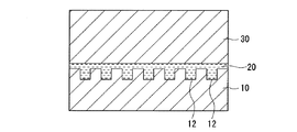
- a mold having a reverse pattern of the fine pattern on its surface is pressed against a photocurable material arranged on the surface of the substrate.
- a method photo nanoimprint method in which light is applied to the photocurable material, the photocurable material is cured, and a fine pattern is formed on the surface of a substrate (see Patent Documents 1 and 2). ).
- the refractive index may be required to be 1.54 or more. Therefore, a high refractive index may be required for a cured product of the photocurable material.
- As means for increasing the refractive index it has been studied to disperse inorganic fine particles having a refractive index higher than that of an organic material in a photocurable material.
- Patent Document 3 As a method for dispersing the inorganic fine particles in the photocurable material, a method is known in which the surface of the inorganic fine particles is modified with a compound having a high affinity with the photocurable material (Patent Document 3).
- Patent Document 3 a method in which the surface of the inorganic fine particles is modified with a compound having a high affinity with the photocurable material.
- the inorganic fine particles obtained by this method have good dispersibility in the photocurable material before curing, they are extruded along with crosslinking when the photocurable material is cured, and the extruded inorganic fine particles are precipitated or agglomerated. As a result, the transparency of the cured product is impaired.
- Patent Document 4 As a method for maintaining the dispersion of the inorganic fine particles even when the photocurable material is cured, there is a method in which the inorganic fine particles modified with a compound having a high affinity are further modified with a compound having the same reactive site as the photocurable material.
- Patent Document 4 Since the inorganic fine particles modified by this method have the same reaction point as the photocurable material, they are fixed in the cured product in a dispersed state when the photocurable material is cured. However, in this method, the compound that modifies the inorganic fine particles becomes bulky, resulting in problems that the refractive index as designed cannot be obtained and the refractive index is lowered.
- Non-Patent Document 1 a method of modifying inorganic fine particles with acrylic acid has been proposed. Since the molecular weight of acrylic acid is small, the compound that modifies the inorganic fine particles is not bulky and looks like a good method at first glance. However, since acrylic acid alone cannot sufficiently cover the polarity of the surface of the inorganic fine particles, the inorganic fine particles modified with acrylic acid have a relatively high polarity. Therefore, the following problems arise.
- the inorganic fine particles are usually provided as an aqueous sol, it is necessary to extract from the aqueous sol with an organic solvent before adding the inorganic fine particles modified with acrylic acid to the photocurable material.
- organic solvent such as methanol
- inorganic fine particles modified with acrylic acid can be dispersed only in an organic solvent (such as methanol) having a relatively high polarity. Therefore, before extraction, filtration, solvent substitution, etc. are needed, and a process increases.
- the photocurable material to be dispersed is also limited to those having relatively high polarity (such as non-fluorinated (meth) acrylates).
- the photocurable material When dispersing inorganic fine particles in a photocurable material containing highly hydrophobic fluoro (meth) acrylates, fluorine-based surfactants, etc., the photocurable material while suppressing the bulk of the compound that modifies the inorganic fine particles as much as possible. It is necessary to impart affinity to the inorganic fine particles and to introduce reaction points with the photocurable material. However, as described above, in the conventional method, the bulk of the compound that modifies the inorganic fine particles is suppressed as much as possible, the affinity to the photocurable material is imparted to the inorganic fine particles, and the reaction point with the photocurable material is set. Is also difficult to introduce.
- the present invention provides a photocurable material capable of forming a cured product having a high refractive index and a high transparency, a method capable of easily producing the material, and an article having a high refractive index and a high transparency.
- the method for producing a photocurable material of the present invention includes the following steps (i) to (iii). (I) reacting a polymerizable component (A) comprising at least one compound (a) having a (meth) acryloyloxy group with a compound (B) having a mercapto group and a carboxy group, to thereby react the compound (B) A step of obtaining a surface modifying agent (C) having a carboxy group derived from the terminal. (Ii) A step of obtaining the surface modified inorganic fine particles (E) by modifying the surface of the inorganic fine particles (D) with the surface modifier (C).
- the number of moles of the polymerizable component (A) in the step (i) is preferably 0.5 to 10 times the number of moles of the compound (B).
- the mass of the inorganic fine particles (D) in the step (ii) is preferably 0.2 to 10 times the mass of the compound (B) used in the step (i).
- the total of the polymerizable component (A), the compound (B), the inorganic fine particles (D), the polymerizable component (F), and the photopolymerization initiator (G) can be obtained by displaying the raw material charge ratio ( 100% by mass), the total of the polymerizable component (A) and the polymerizable component (F) is 10 to 98.8% by mass, and the compound (B) is 0.01 to 28% by mass.
- the inorganic fine particles (D) are 0.1 to 75% by mass
- the photopolymerization initiator (G) is 0.1 to 9% by mass.
- the pKa of the compound (B) is preferably 4.4 or less.
- the compound (B) preferably satisfies the following conditions (1) to (3).
- Condition (1) having one or more mercapto groups.
- Condition (2) having one or more carboxy groups.
- Condition (3) No primary amino group.
- the compound (B) is an aliphatic carboxylic acid having 2 to 20 carbon atoms and has a mercapto group at least in any of the ⁇ -position, ⁇ -position and ⁇ -position of the carboxyl group, and does not have a primary amino group. A compound is preferred.
- the molecular weight of the compound (B) is preferably 600 or less.
- the inorganic fine particles (D) are preferably metal oxide fine particles.
- the metal oxide is titanium oxide, zirconium oxide, aluminum oxide, barium titanate, cerium oxide, tin oxide, zinc oxide, tantalum oxide, manganese oxide, nickel oxide, iron oxide, silicon oxide, niobium oxide, lanthanum oxide and oxidation. It is preferably at least one selected from the group consisting of gadolinium.
- the average primary particle diameter of the inorganic fine particles (D) is preferably 2 to 100 nm.
- the polymerizable component (F) preferably contains a compound (f2) having a fluorine atom and having one or more (meth) acryloyloxy groups.
- the polymerizable component (F) is a compound (f1) having two or more (meth) acryloyloxy groups (excluding the compound (f2)), a fluorine atom, and a (meth) acryloyloxy group.
- the compound (f2) and the compound (f3) having one (meth) acryloyloxy group (excluding the compound (f2)), wherein the compound (f1), the compound (f2) and the compound Of the total (100% by mass) of the compound (f3), the compound (f1) is 15 to 70% by mass, the compound (f2) is 5 to 45% by mass, and the compound (f3) is It is preferably 10 to 65% by mass.
- the polymerizable component (A) is preferably composed of one or more of the compounds (f) constituting the polymerizable component (F). It is preferable that the polymerizable component (A) is the same polymerizable component as the polymerizable component (F).
- the photocurable material of the present invention is obtained by the production method of the present invention.
- the photocurable material of the present invention preferably contains substantially no solvent.
- the article of the present invention is a product obtained by curing the photocurable material of the present invention, or has a cured film formed by curing the photocurable material of the present invention on the surface of a substrate.
- a photocurable material capable of forming a cured product having a high transparency and a high refractive index can be easily produced.
- the photocurable material of the present invention can form a cured product having high transparency and high transparency.
- the article of the present invention has high transparency and refractive index.
- a compound represented by the formula (f21) is referred to as a compound (f21).
- a (meth) acryloyloxy group means an acryloyloxy group or a methacryloyloxy group.
- (meth) acrylate means an acrylate or a methacrylate.
- the method for producing a photocurable material of the present invention is a method having the following steps (i) to (iii).
- a polymerizable component (A) composed of one or more compounds (a) having a (meth) acryloyloxy group is reacted with a compound (B) having a mercapto group and a carboxy group to give the compound (B)
- Photocuring comprising surface-modified inorganic fine particles (E), a polymerizable component (F) composed of one or more compounds (f) having a (meth) acryloyloxy group, and a photopolymerization initiator (G).
- E surface-modified inorganic fine particles
- F polymerizable component
- G photopolymerization initiator
- Step (i) is a step of reacting the polymerizable component (A) with the compound (B) to obtain a surface modifier (C) having a carboxy group derived from the compound (B) at the terminal.
- the polymerizable component (A) is a polymerizable component composed of one or more compounds (a).
- the compound (a) is a compound having a (meth) acryloyloxy group, and examples thereof include those exemplified as the compound (f) described later.
- the polymerizable component (A) from the viewpoint of dispersibility of the surface-modified inorganic fine particles (E) in the polymerizable component (F), one of the compounds (f) constituting the polymerizable component (F) described later is used.
- a polymerizable component comprising at least species is preferable, and the same polymerizable component as the polymerizable component (F) is more preferable.
- the same polymerizable component means that the types and ratios of the compounds are the same.
- the compound (B) is a compound having a mercapto group and a carboxy group.
- the mercapto group reacts with the carbon-carbon unsaturated double bond of the (meth) acryloyloxy group of the polymerizable component (A).
- the high affinity of the carboxy group derived from the compound (B) capable of binding to the inorganic fine particles (D) and the polymerizable component (F) and the polymerizable property serving as a reaction point between the polymerizable component (F).
- a surface modifier (C) having a structure derived from the component (A) is obtained.
- it is an unreacted mercapto group in the step (i), it becomes a reaction point with the polymerizable component (F).
- the mercapto group may be protected by a protecting group.
- the protecting group may be removed and then reacted with the polymerizable component (A), or may be reacted with the polymerizable component (A) under deprotection conditions.
- the protecting group include known protecting groups such as a trityl group, a benzyl group, and a disulfide bond.
- the number of carboxy groups in the compound (B) may be one or plural. In the case of a plurality, it is preferably 2.
- the compound (B) preferably has a pKa of 4.4 or less.
- the surface modification inorganic fine particles (E) are obtained by modifying the inorganic fine particles (D) using the surface modifier (C) having a carboxy group derived from the compound (B) at the terminal. At this time, it is preferable that the carboxy group of the surface modifier (C) is sufficiently dissociated.
- the carboxy group of the surface modifier (C) is sufficiently dissociated and the modification of the inorganic fine particles (D) proceeds smoothly.
- the lower limit value of the pKa of the compound (B) is not particularly limited, but for reasons such as the type of compounds that are usually available and the durability of the cured product of the photocurable material obtained by the present invention, ⁇ 2 is preferred and 0 is particularly preferred. Therefore, the pKa range of the compound (B) is preferably ⁇ 2 to 4.4, and particularly preferably 0 to 4.3.
- the pKa of the compound (B) in the present invention is a value calculated from the measured value by measuring the pH of the aqueous solution of the compound (B) at 20 ° C.
- Condition (1) having one or more mercapto groups.
- Condition (2) having one or more carboxy groups.
- Condition (3) No primary amino group.
- the carboxy group derived from the compound (B) is bonded to the surface of the inorganic fine particles (D). If the carboxy group is sufficiently dissociated, it is easy to bond to the surface of the inorganic fine particles (D). Therefore, the compound (B) may have a substituent so as to adjust the acidity of the carboxy group.
- the type, number and substitution position of the substituent in the compound (B) are as follows.
- the carboxy group in the compound (B) (and thus the carboxy group in the surface modifier (C)) is inorganic fine particles (as a whole). What is necessary is just to adjust so that it may have the acidity which can couple
- N-acylamino group such as N-acetylamino group, secondary amino group, tertiary amino group, quaternary ammonium group, imino group, halogen atom, alkoxy group, hydroxyl group, formyl group, keto group, carboxy group, acid chloride Ester group, amide group, cyano group, nitroso group, nitro group, alkenyl group, alkynyl group, aryl group, phenyl group, cycloalkyl group, heterocyclic group, thioether group, mercapto group, sulfonyl group, Fmoc (9-full (Oleenylmethyloxycarbonyl) group and the like.
- N-acylamino group such as N-acetylamino group, secondary amino group, tertiary amino group, quaternary ammonium group, imino group, halogen atom, alkoxy group, hydroxyl group, formyl group, keto group, carb
- halogen atoms, keto groups, carboxy groups, cyano groups, nitro groups and the like which are generally understood to have electron-withdrawing properties, are preferred, but other substituents and N-acylamino groups
- the carboxyl group of the compound (B) generally has an electron-donating property within a range in which the carboxyl group of the compound (B) can take an appropriate dissociation state for the modification of the inorganic fine particles (D), depending on the combination and the substitution position of Groups can also be combined as appropriate.
- the substituent is a mercapto group
- the mercapto group may satisfy the condition (1) at the same time.
- the compound (B) does not have a primary amino group.
- the inorganic fine particles (D) are likely to aggregate in the step (ii). Moreover, it reacts with a carboxy group over time and causes coloring.
- the compound (B) is an aliphatic carboxylic acid having 2 to 20 carbon atoms, having a mercapto group at least in any of the ⁇ -position, ⁇ -position and ⁇ -position of the carboxyl group, and having a primary amino group.
- the compound is not.
- the “carbon number” is a number including carbon atoms in the carboxyl group (—COOH).
- the site structure of the aliphatic carboxylic acid excluding the carboxyl group may be a linear structure or a branched structure.
- the unsaturated bond may be included.
- the site is preferably a linear or branched aliphatic saturated hydrocarbon group.
- the aliphatic carboxylic acid may have a substituent as described above.
- a cysteine derivative in which an amino group is substituted with an acyl group is also preferable.
- the molecular weight of the compound (B) is preferably 600 or less, and more preferably 400 or less. When the molecular weight exceeds 600, the affinity for the polymerizable component (A), the polymerizable component (F) and the organic solvent increases due to the long-chain alkyl group, etc., but the molecule becomes bulky. ) And the optical properties of the polymerizable component (F) and the optical properties of the inorganic fine particles (D) do not produce the results as designed, or may decrease from the target refractive index. .
- Examples of the compound (B) include the following compounds.
- the molecular weight in parentheses for each compound is the molecular weight.
- the mercapto group of the compound may be protected with a protective group, the compounds may be disulfide bonded, or may further have a substituent.
- the surface modifier (C) is obtained by reacting the polymerizable component (A) with the compound (B). This reaction is a reaction between the carbon-carbon unsaturated double bond of the (meth) acryloyloxy group of the polymerizable component (A) and the mercapto group of the compound (B), that is, an ene-thiol reaction.
- the reason for reacting the polymerizable component (A) and the compound (B) is as follows.
- the compound (B) is reacted with the polymerizable component (A) of the same type as the polymerizable component (F) in which the inorganic fine particles (D) are dispersed so as to approach the ideal state.
- a carboxy group capable of binding to the inorganic fine particles (D) is introduced.
- the structure derived from the polymerizable component (A) having high affinity with the polymerizable component (F) is converted into the structure of the third component other than the polymerizable component (A) and the inorganic fine particles (D). It can be introduced on the surface of the inorganic fine particles (D) with the existence reduced as much as possible.
- This reaction is performed, for example, by dissolving the compound (B) in an organic solvent, adding a polymerizable component (A) and a photopolymerization initiator to the compound, and irradiating with light.
- the reaction does not have to be performed completely, and unreacted substances may remain.
- the compound (B) may react with the terminal of a polymer obtained by polymerizing a part of the polymerizable component (A).
- the number of moles of the polymerizable component (A) is preferably 0.5 to 10 times, more preferably 0.9 to 5 times the number of moles of the compound (B).
- the number of moles of the polymerizable component (A) is less than 0.5 times the number of moles of the compound (B)
- the unreacted compound (B) that is, the polymerizable component (A) and the surface modifier (C)
- Surface modifiers that have insufficient affinity with the polymerizable component (F) will increase, and the inorganic fine particles (D) will easily aggregate in step (ii).
- the number of moles of the polymerizable component (A) exceeds 10 times the number of moles of the compound (B)
- the number of carboxy groups in the surface modifier (C) becomes relatively small. D) cannot be extracted sufficiently.
- the organic solvent is not particularly limited as long as it can dissolve the polymerizable component (A), the compound (B) and the photopolymerization initiator and does not react with them, and is preferably an organic solvent having low solubility in water.
- the compound (B) is preferably dissolved in the organic solvent in the range of 10 to 200 mg / mL.
- the addition amount of the photopolymerization initiator is preferably 0.1 to 5 parts by mass with respect to 100 parts by mass in total of the polymerizable component (A) and the compound (B).
- the kind of light should just be selected suitably according to a photoinitiator, for example, the ultraviolet-ray which has a dominant wavelength in 365 nm is mentioned.
- the light irradiation time is, for example, 1 minute to 3 hours for an irradiation density of 10 mW.
- the reaction in step (i) may be performed in two or more stages.
- Step (ii) is a step of obtaining the surface-modified inorganic fine particles (E) by modifying the surface of the inorganic fine particles (D) with the surface modifier (C).
- metal oxide fine particles are preferable.
- the metal oxide include oxides of at least one metal selected from the group consisting of metals belonging to Group 4 of the periodic table, metals belonging to Group 13 of the periodic table, and metals belonging to Group 14 of the periodic table.
- metals belonging to Group 4 of the periodic table include Ti, Zr, and Hf.
- the metal belonging to Group 13 of the periodic table include Al, Ga, and In.
- metals belonging to Group 14 of the periodic table include Si, Ge, Sn, and Pb.
- Metal oxides include titanium oxide, zirconium oxide, aluminum oxide, barium titanate, cerium oxide, tin oxide, zinc oxide, tantalum oxide, manganese oxide, nickel oxide, iron oxide, silicon oxide, niobium oxide, lanthanum oxide, oxidation Gadolinium is preferred.
- the average primary particle diameter of the inorganic fine particles (D) is preferably 2 nm to 100 nm, more preferably 4 nm to 60 nm. If the average primary particle diameter is 100 nm or less, the transparency of the cured product in the visible light region can be maintained. When the average primary particle diameter is 2 nm or more, an increase in the necessary amount of the compound (B) accompanying the enlargement of the total specific surface area of the fine particles can be avoided.
- the average primary particle diameter of the inorganic fine particles (D) is measured by a dynamic scattering method in a dispersion state.
- the inorganic fine particles (D) may be used alone or in combination of two or more, or may be fine particles of a composite metal oxide composed of two or more.
- Examples of the form of the inorganic fine particles (D) include a powder, a dispersion (sol) dispersed in a solvent (dispersion medium), and the dispersion is preferable from the viewpoint of the transparency of the cured product.
- An aqueous dispersion that is water is more preferred.
- the concentration of the inorganic fine particles (D) in the aqueous dispersion is preferably 1 to 35% by mass, more preferably 2 to 20% by mass. If the concentration is too thin, the extraction efficiency of the surface-modified inorganic fine particles (E) from the aqueous dispersion is deteriorated. When the concentration is too high, the inorganic fine particles (D) are aggregated in the aqueous dispersion due to mechanical stress applied when the surface-modified inorganic fine particles (E) are extracted from the aqueous dispersion.
- the surface-modified inorganic fine particles (E) are obtained by modifying the surface of the inorganic fine particles (D) with the surface modifier (C).
- the modification is performed, for example, by mixing a solution obtained by dissolving the surface modifier (C) in an organic solvent having low solubility in water and an aqueous sol of inorganic fine particles (D), and then modifying the surface modified inorganic fine particles (E) into the organic solvent. Is done by extracting.
- the mass of the inorganic fine particles (D) is preferably 0.2 to 10 times, more preferably 0.67 to 10 times the mass of the compound (B) used in the step (i).
- the mass of the inorganic fine particles (D) exceeds 10 times the mass of the compound (B) used in the step (i)
- the inorganic fine particles (D) cannot be sufficiently extracted, and the inorganic fine particles that have not been extracted ( D) will aggregate.
- the surplus surface modifier (C) has a surface active action, so that the surface modifier (C)
- the solution and the aqueous dispersion medium of the inorganic fine particles (D) are emulsified.
- the aqueous solvent is removed by a known method such as decantation or a separatory funnel to obtain an extract of the surface-modified inorganic fine particles (E).
- the extract contains water
- the water dissolved in the extract can be further removed by adding a highly hydrophobic organic solvent such as hexane to the extract.
- the extract is concentrated by a known method such as distillation under reduced pressure before the step (iii) described later or is substantially free of solvent.
- a known method such as distillation under reduced pressure before the step (iii) described later or is substantially free of solvent.
- the reason is as follows. Since a structure derived from the polymerizable component (A) having a high affinity with the polymerizable component (F) is introduced on the surface of the inorganic fine particles (D), a solvent having a somewhat lower affinity remains as much as possible.
- the extract of the surface-modified inorganic fine particles (E) is temporarily stored or when the polymerizable component (F) is mixed in the step (iii), the phase separation or the surface-modified inorganic fine particles (E) Aggregation can be suppressed.
- a small amount of alcohol such as methanol or ethanol during the distillation under reduced pressure because water azeotropes.
- Step (iii) is a step of obtaining a photocurable material containing the surface-modified inorganic fine particles (E), the polymerizable component (F), and the photopolymerization initiator (G).
- the polymerizable component (F) is a polymerizable component comprising at least one compound (f) having a (meth) acryloyloxy group.
- a compound (f) may be used individually by 1 type, and may use 2 or more types together.
- As the polymerizable component (F), three types of combinations of the compound (f1), the compound (f2), and the compound (f3) are preferable from the viewpoint of releasability, mechanical strength, and transparency of the cured product.
- Compound (f1) is a compound having two or more (meth) acryloyloxy groups (excluding compound (f2)).
- the number of (meth) acryloyloxy groups in the compound (f1) is preferably from 2 to 10, particularly preferably from 2 to 6.
- Examples of the compound (f1) include (meth) acrylates of bisphenols, (meth) acrylates having a fluorene skeleton, (meth) acrylates having a naphthalene skeleton, (meth) acrylates of diols such as glycols, glycerol and trimethylol Examples include (meth) acrylates of triols and (meth) acrylates of tetraols such as pentaerythritol, (meth) acrylates of diols, (meth) acrylates of triols, and (meth) acrylates of tetraols are preferred.
- Examples of the compound (f1) include the following compounds.
- a monomer having a urethane bond or a monomer containing a silicon atom such as 1,3-bis (3-methacryloyloxypropyl) -1,1,3,3-tetramethyldisiloxane can also be employed.
- Compound (f1) may be used alone or in combination of two or more.
- the ratio of the compound (f1) is 15 to 70% by mass, preferably 25 to 60% by mass, out of the total (100% by mass) of the compound (f1), the compound (f2) and the compound (f3).
- the amount of the compound (f1) is 15% by mass or more, the cured product has good mechanical strength. If the amount of the compound (f1) is 70% by mass or less, the cured product will not undergo phase separation.
- the compound (f2) is a compound having a fluorine atom and having at least one (meth) acryloyloxy group.
- Examples of the compound (f2) include fluoro (meth) acrylates. Fluoro (meth) acrylates are preferable in terms of compatibility.
- Fluoro (meth) acrylates are preferably compound (f21) from the viewpoints of compatibility and environmental characteristics.
- R 1 is a hydrogen atom or a methyl group
- R 2 and R 3 are each a hydrogen atom or an alkyl group having 1 to 4 carbon atoms
- R 4 and R 5 are a fluorine atom and a carbon number, respectively.
- Is a perfluoroalkyl group having 1 to 4 carbon atoms or a perfluoroalkoxy group having 1 to 4 carbon atoms
- R 6 is a hydrogen atom or a fluorine atom
- m is an integer of 1 to 4
- n is It is an integer from 1 to 16.
- n is preferably an integer of 1 to 10 from the viewpoint of compatibility, and more preferably an integer of 3 to 6 from the viewpoint of environmental characteristics.
- the amount of the compound (f2) is 5 to 45% by mass, preferably 15 to 35% by mass, of the total (100% by mass) of the compound (f1), the compound (f2) and the compound (f3).
- the amount of the compound (f2) is 5% by mass or more, a cured product having excellent releasability can be obtained, and foaming of the photocurable material can be suppressed. Since the foaming of the photocurable material can be suppressed, it is easy to filter during preparation, and further, defects in the pattern shape due to mixing of bubbles can be eliminated during nanoimprinting. If the amount of the compound (f2) is 45% by mass or less, a cured product having excellent mechanical strength can be obtained because it can be uniformly mixed.
- the compound (f3) is a compound having one (meth) acryloyloxy group (excluding the compound (f2)).
- the compound (f3) is a component that dissolves other components and is a component that improves the compatibility between the compound (f1) and the compound (f2). If the compatibility between the compound (f1) and the compound (f2) is good, the foaming during the preparation of the photocurable material is suppressed, and the photocurable material can be easily prepared, for example, through a filter. Can be obtained. Furthermore, by obtaining a homogeneous cured product, it is possible to sufficiently exhibit mold releasability and mechanical strength.
- an organic group having 1 to 30 carbon atoms is preferably bonded to the oxygen atom of the ester structure (COO—).
- the carbon number of the organic group is particularly preferably 4 to 20, and particularly preferably 4 to 12.
- Examples of the organic group include a linear alkyl group, a branched alkyl group, a cycloalkyl group, an alkyl group substituted with an aryl group, an allyl group, a bridged hydrocarbon group, a group having a repeating structure of an oxyalkylene chain, and an aromatic group And heterocyclic groups.
- These groups may be substituted with a heteroatom such as a nitrogen atom or an oxygen atom or a silicon atom, or may be substituted with a functional group such as a hydroxyl group or an amino group, and an unsaturated bond or a free carboxyl group may be substituted. You may have. Among these, a linear alkyl group, a branched alkyl group, a cycloalkyl group, and a bridged hydrocarbon group are preferable among these. Examples of the compound (f3) include the following compounds.
- the amount of the compound (f3) is 10 to 65% by mass, preferably 15 to 50% by mass, out of the total (100% by mass) of the compound (f1), the compound (f2) and the compound (f3).
- the amount of the compound (f3) is 10% by mass or more, the compatibility between the compound (f1) and the compound (f2) is good.
- the amount of the compound (f3) is 65% by mass or less, the sensitivity becomes a value of 1000 mJ / cm 2 or less, and the photocurable material exhibits good sensitivity.
- Photopolymerization initiator (G) examples include acetophenone photopolymerization initiator, benzoin photopolymerization initiator, benzophenone photopolymerization initiator, thioxanthone photopolymerization initiator, ⁇ -aminoketone photopolymerization initiator, ⁇ -hydroxy Ketone-based photopolymerization initiator, ⁇ -acyl oxime ester, benzyl- (o-ethoxycarbonyl) - ⁇ -monooxime, acylphosphine oxide, glyoxy ester, 3-ketocoumarin, 2-ethylanthraquinone, camphorquinone, tetramethylthiuram
- examples thereof include sulfide, azobisisobutyronitrile, benzoyl peroxide, dialkyl peroxide, tert-butyl peroxypivalate, and the like.
- acetophenone photopolymerization initiator benzoin photopolymerization initiator, ⁇ -Aminoketone photopolymerization
- An initiator or a benzophenone photopolymerization initiator is preferred.
- acetophenone photopolymerization initiator examples include the following compounds. Acetophenone, p- (tert-butyl) 1 ′, 1 ′, 1′-trichloroacetophenone, chloroacetophenone, 2 ′, 2′-diethoxyacetophenone, hydroxyacetophenone, 2,2-dimethoxy-2′-phenylacetophenone, 2 -Aminoacetophenone, dialkylaminoacetophenone, etc.
- benzoin photopolymerization initiator examples include the following compounds. Benzyl, benzoin, benzoin methyl ether, benzoin ethyl ether, benzoin isopropyl ether, benzoin isobutyl ether, 1-hydroxycyclohexyl phenyl ketone, 2-hydroxy-2-methyl-1-phenyl-2-methylpropan-1-one, 1- (4-Isopropylphenyl) -2-hydroxy-2-methylpropan-1-one, benzyldimethyl ketal and the like.
- Examples of the ⁇ -aminoketone photopolymerization initiator include the following compounds. 2-benzyl-2-dimethylamino-1- (4-morpholinophenyl) -butanone-1, 2-methyl-1 [4- (methylthio) phenyl] -2-morpholinopropan-1-one and the like.
- benzophenone-based photopolymerization initiator examples include the following compounds. Benzophenone, benzoylbenzoic acid, methyl benzoylbenzoate, methyl-o-benzoylbenzoate, 4-phenylbenzophenone, hydroxybenzophenone, hydroxypropylbenzophenone, acrylic benzophenone, 4,4′-bis (dimethylamino) benzophenone, etc.
- a photoinitiator (G) may be used individually by 1 type, and may use 2 or more types together.
- the photocurable material may contain an additive (H) excluding the surface-modified inorganic fine particles (E), the polymerizable component (F), and the photopolymerization initiator (G).
- additive (H) include surfactants, photosensitizers, other resins, carbon compounds, metal fine particles, and other organic compounds.
- a fluorine-containing surfactant is preferable. When the fluorine-containing surfactant is used, the effect of improving the releasability of the cured product is also exhibited.
- a fluorine-containing surfactant having a fluorine content of 10 to 70% by mass is preferable, and a fluorine-containing surfactant having a fluorine content of 10 to 40% by mass is more preferable.
- the fluorine-containing surfactant may be water-soluble or fat-soluble, and is preferably fat-soluble from the viewpoint of compatibility in the photocurable material and dispersibility in the cured product.
- an anionic fluorine-containing surfactant As the fluorine-containing surfactant, an anionic fluorine-containing surfactant, a cationic fluorine-containing surfactant, an amphoteric fluorine-containing surfactant, or a nonionic fluorine-containing surfactant is preferable, and compatibility in a photocurable material, From the viewpoint of dispersibility in the cured product, a nonionic fluorine-containing surfactant is more preferable.
- anionic fluorine-containing surfactant a polyfluoroalkyl carboxylate, a polyfluoroalkyl phosphate, or a polyfluoroalkyl sulfonate is preferable.
- Specific examples of the anionic fluorine-containing surfactant include Surflon S-111 (trade name, manufactured by AGC Seimi Chemical Co., Ltd.), Fluorad FC-143 (trade name, manufactured by Sumitomo 3M), and Megafuck F-120 (trade name). DIC, etc.).
- a trimethylammonium salt of polyfluoroalkylcarboxylic acid or a trimethylammonium salt of polyfluoroalkylsulfonic acid amide is preferable.
- Specific examples of the cationic fluorine-containing surfactant include Surflon S-121 (trade name, manufactured by AGC Seimi Chemical Co., Ltd.), Florard FC-134 (trade name, manufactured by Sumitomo 3M Limited), and Megafuck F-150 (trade name). DIC, etc.).
- amphoteric fluorine-containing surfactant polyfluoroalkyl betaine is preferable.
- amphoteric fluorine-containing surfactant include Surflon S-132 (trade name, manufactured by AGC Seimi Chemical Co., Ltd.), Florard FX-172 (trade name, manufactured by Sumitomo 3M), MegaFuck F-120 (trade name, DIC) and the like.
- nonionic fluorine-containing surfactant polyfluoroalkylamine oxide or polyfluoroalkyl / alkylene oxide adduct is preferable.
- specific examples of the nonionic fluorine-containing surfactant include Surflon S-145 (trade name, manufactured by AGC Seimi Chemical Co., Ltd.), Surflon S-393 (trade name, manufactured by AGC Seimi Chemical Co., Ltd.), and Surflon KH-20 (trade name).
- examples thereof include amine compounds such as tetramine and 4,4′-bis (dialkylamino) benzophenone.
- Examples of other resins include polystyrene, polythiophene, polyester oligomer, polycarbonate, poly (meth) acrylate, and the like.
- Examples of the carbon compound include carbon nanotubes and fullerenes.
- Examples of the metal fine particles include copper and platinum.
- Examples of other organic compounds include porphyrin and metal-encapsulated polyphyllin.
- the total amount of the additive (H) is preferably 10% by mass or less in the photocurable material (100% by mass). If the total amount of the additive (H) is 10% by mass or less, it can be uniformly mixed with the photocurable material, and a homogeneous photocurable material can be obtained.
- the timing of adding the additive (H) may be any of steps (i) to (iii) or after step (iii), and is preferably after step (iii).
- the photocurable material is prepared, for example, by adding the polymerizable component (F) to the surface-modified inorganic fine particles (E), stirring well, then adding the photopolymerization initiator (G), and stirring well.
- the surface-modified inorganic fine particles (E) may be in the state of an extract, may be in a state in which the extract is concentrated, or may be in a state that does not substantially contain a solvent.
- the photocurable material is substantially removed from the solvent by a known method such as distillation under reduced pressure. Do not include.
- step (i) the polymerizable component (A) is changed into the surface modifier (C) together with the compound (B). Therefore, in the photocurable material, the idea of minimizing the amount of the surface modifier (C) used, and the surface modifier (C) is no longer the polymerizable component (A) or the polymerizable component (F). Since it does not have an equivalent photocuring property, the step (iii) is performed from the viewpoint of imparting the photocuring property.
- the mass ratio of the polymerizable component (F) to the mass of the polymerizable component (A) in the step (i) is the inorganic fine particles (D) of the photocurable material to be finally obtained. ) Varies depending on the content.
- the mass ratio of the polymerizable component (F) to the mass of the polymerizable component (A) in the step (i) is large.
- the amount of the polymerizable component (F) relative to the mass of the polymerizable component (A) in the step (i) becomes smaller.
- the mass ratio (A / F) is preferably 0.01 to 100, more preferably 0.1 to 10.
- the photocurable material obtained is substantially only the surface-modified inorganic fine particles (E). Therefore, a polymerizable component designed as a photocurable material.
- the curability, viscosity and the like of (A) and the polymerizable component (F) are greatly different in the end, or the handleability of the photocurable material is impaired due to thixotropy.
- the mass ratio (A / F) is more than 100, that is, in step (ii), an attempt is made to extract the inorganic fine particles (D) with a very small amount of the surface modifier (C).
- the manufacturing method does not work well.
- the ratio of each raw material in the steps (i) to (iii) is as follows.
- the total ratio of the polymerizable component (A) and the polymerizable component (F) is as follows: the polymerizable component (A), the compound (B), the inorganic fine particles (D), the polymerizable component (F), and the photopolymerization initiator (G ) Is preferably 10 to 98.8% by mass, more preferably 15 to 98% by mass. If the total ratio of the polymerizable component (A) and the polymerizable component (F) is 10% by mass or more, the photocurable material has sufficient photocurability. When the total ratio of the polymerizable component (A) and the polymerizable component (F) is 98.8% by mass or less, the respective raw materials are easily mixed uniformly.
- the ratio of the compound (B) is the total of the polymerizable component (A), the compound (B), the inorganic fine particles (D), the polymerizable component (F) and the photopolymerization initiator (G) (100% by mass). 0.01 to 28% by mass is preferable, and 0.1 to 15% by mass is more preferable. If the ratio of a compound (B) is 0.01 mass% or more, dispersion
- the proportion of the inorganic fine particles (D) is the total (100% by mass) of the polymerizable component (A), the compound (B), the inorganic fine particles (D), the polymerizable component (F) and the photopolymerization initiator (G). 0.1 to 75% by mass is preferable, and 2 to 57% by mass is more preferable. When the proportion of the inorganic fine particles (D) is 0.1% by mass or more, the effect of modifying physical properties by forming a composite material with the inorganic fine particles (D) appears. When the proportion of the inorganic fine particles (D) is 75% by mass or less, the inorganic fine particles (D) can be dispersed without agglomeration.
- a photoinitiator (G) Content of a photoinitiator (G) is 0. of the sum total (100 mass%) of a polymeric component (A), a compound (B), a polymeric component (F), and a photoinitiator (G). 1 to 9% by mass is preferable, and 0.5 to 6% by mass is more preferable. If the ratio of a photoinitiator (G) is 0.1 mass% or more, a hardened
- step (i) the polymerizable component (A) and compound (B) are reacted to obtain a surface modifier (C), and then in step (ii) the surface of the inorganic fine particles (D) is surface modified.
- the surface-modified inorganic fine particles (E) are obtained by modification with (C), the structure derived from the polymerizable component (A) having a high affinity with the polymerizable component (F) and being a polymerizable group, It can be easily introduced onto the surface of the inorganic fine particles (D) with the presence of the third component other than the polymerizable component (A) and the inorganic fine particles (D) reduced as much as possible. Since the surface-modified inorganic fine particles (E) have both an affinity with the polymerizable component (F) and a polymerizable group, the photocurable material obtained in the step (iii) and the surface at the time of curing thereof Dispersibility of the modified inorganic fine particles (E) is maintained. Moreover, the compound which modifies inorganic fine particles (D) is not bulky. As a result, a highly transparent cured product with high transparency can be formed.
- the photocurable material of the present invention is a composition obtained by the production method of the present invention, and includes surface-modified inorganic fine particles (E), a polymerizable component (F), and a photopolymerization initiator (G).
- the photocurable material of the present invention preferably contains substantially no solvent. If the photo-curing material does not substantially contain a solvent, the photo-curing property can be obtained without performing a special operation (eg, removing the solvent by heating the photo-curing material to a high temperature) except for light irradiation. The material can be easily cured.
- the solvent is a compound having the ability to dissolve or disperse any of the surface-modified inorganic fine particles (E), the polymerizable component (F), and the photopolymerization initiator (G).
- the phrase “substantially free of solvent” means that it contains no solvent at all or may contain the solvent used in preparing the photocurable material as a residual solvent. However, the residual solvent is preferably removed as much as possible, and more preferably 10% by mass or less in the photocurable material (100% by mass).
- the sensitivity of the photocurable material of the present invention is as follows: from a high pressure mercury lamp (light source having dominant wavelengths at 254, 315, and 365 nm at 1.5 to 2.0 kHz) to a photocurable material having a thickness of about 1.5 ⁇ m. It can be represented by an integrated light amount until light is irradiated and the photocurable material is completely cured.
- the cumulative amount of light is preferably 1000 mJ / cm 2 or less, 150mJ / cm 2 ⁇ 750mJ / cm 2 is more preferable. When the integrated light quantity exceeds 1000 mJ / cm 2 , it takes 20 seconds or more to cure the photocurable material, resulting in a decrease in production efficiency.
- the photocurable material of the present invention preferably has a refractive index of 1.54 or more at a wavelength of 589 nm after curing, more preferably 1.54 to 1.62. If the refractive index is less than 1.54, the focal length cannot be significantly reduced, so the size of an optical element such as a microlens array cannot be reduced.
- the refractive index at a wavelength of 589 nm of the cured photocurable material is measured at 23 ° C. using an Abbe refractometer.
- the contact angle with respect to water after curing of the photocurable material of the present invention is a measure of the releasability of the cured product.
- the contact angle is preferably 75 ° or more, and more preferably 80 to 116 °. When the contact angle is less than 75 degrees, it is difficult to release the mold, and the photocurable material adheres to the mold, which may damage the mold.
- the contact angle is measured according to JIS R3257.
- the surface modification has both a high affinity for the polymerizable component (F) and a polymerizable group, and the compound for modifying the inorganic fine particles (D) is not bulky. Since inorganic fine particles (E) are contained, a highly transparent cured product with high transparency can be formed.
- the article of the present invention is obtained by curing the photocurable material of the present invention, or has a cured film formed by curing the photocurable material of the present invention on the surface of a substrate.
- a method for producing a molded body having a fine pattern on the surface will be described.
- the method for producing a molded body having a fine pattern on the surface has the following steps (1) to (3).
- the substrate examples include an inorganic material substrate or an organic material substrate.
- the inorganic material examples include silicon wafer, glass, quartz glass, metal (aluminum, nickel, copper, etc.), metal oxide (alumina, etc.), silicon nitride, aluminum nitride, lithium niobate, and the like.
- the organic material examples include fluorine resin, silicone resin, acrylic resin, polycarbonate, polyester (polyethylene terephthalate, etc.), polyimide, polypropylene, polyethylene, nylon resin, polyphenylene sulfide, and cyclic polyolefin.
- a surface-treated substrate may be used from the viewpoint of excellent adhesion to the photocurable material.
- the surface treatment include primer coating treatment, ozone treatment, plasma etching treatment, and the like.
- the primer include silane coupling agents and silazanes.
- Examples of the mold include a non-translucent material mold or a translucent material mold.
- Examples of the non-translucent material include a silicon wafer, nickel, copper, stainless steel, titanium, SiC, mica and the like.
- Examples of the light transmitting material include quartz, glass, polydimethylsiloxane, cyclic polyolefin, polycarbonate, polyethylene terephthalate, and transparent fluororesin.
- At least one of the base material and the mold is a material that transmits 40% or more of light having a wavelength at which the photopolymerization initiator (G) acts.
- the mold has a reverse pattern on the surface.
- the reverse pattern is a reverse pattern corresponding to the fine pattern on the surface of the molded body.
- the reverse pattern has fine convex portions and / or concave portions.
- protrusion scattered on the surface, etc. are mentioned.
- the recess include a long groove extending on the surface of the mold and holes scattered on the surface.
- Examples of the shape of the ridge or groove include a straight line, a curved line, a bent shape, and the like. A plurality of ridges or grooves may exist in parallel and have a stripe shape. Examples of the cross-sectional shape of the ridge or groove in the direction perpendicular to the longitudinal direction include a rectangle, a trapezoid, a triangle, and a semicircle. Examples of the shape of the protrusion or hole include a triangular prism, a quadrangular prism, a hexagonal prism, a cylinder, a triangular pyramid, a quadrangular pyramid, a hexagonal pyramid, a cone, a hemisphere, and a polyhedron.
- the average width of the ridges or grooves is preferably 1 nm to 500 ⁇ m, more preferably 10 nm to 100 ⁇ m, and even more preferably 15 nm to 10 ⁇ m.
- the width of the ridge means the length of the base in the cross section in the direction orthogonal to the longitudinal direction.
- the width of the groove means the length of the upper side in the cross section in the direction orthogonal to the longitudinal direction.
- the average width of the protrusions or holes is preferably 1 nm to 500 ⁇ m, more preferably 10 nm to 100 ⁇ m, and further preferably 15 nm to 10 ⁇ m.
- the width of the protrusion means the length of the bottom side in a cross section perpendicular to the longitudinal direction when the bottom surface is elongated, and otherwise means the maximum length of the bottom surface of the protrusion.
- the width of the hole means the length of the upper side in the cross section perpendicular to the longitudinal direction when the opening is elongated, and otherwise means the maximum length of the opening of the hole.
- the average height of the convex portions is preferably 1 nm to 500 ⁇ m, more preferably 10 nm to 100 ⁇ m, and further preferably 15 nm to 10 ⁇ m.
- the average depth of the recesses is preferably 1 nm to 500 ⁇ m, more preferably 10 nm to 100 ⁇ m, and even more preferably 15 nm to 10 ⁇ m.
- the interval between adjacent convex portions is preferably 1 nm to 500 ⁇ m on average, and more preferably 1 nm to 50 ⁇ m.
- the interval between adjacent convex portions means the distance from the end of the base of the cross section of the convex portion to the start of the base of the cross section of the adjacent convex portion.
- the interval between adjacent recesses means the distance from the end of the upper side of the cross section of the recess to the start end of the upper side of the cross section of the adjacent recess.
- the minimum dimension of the convex portion is preferably 1 nm to 300 ⁇ m, more preferably 1 nm to 500 nm, still more preferably 1 nm to 100 nm.
- the minimum dimension means the minimum dimension among the width, length, and height of the convex portion.
- the minimum dimension of the recess is preferably 1 nm to 300 ⁇ m, more preferably 1 nm to 500 nm, and further preferably 1 nm to 100 nm.
- the minimum dimension means the minimum dimension among the width, length and depth of the recess.
- Step (I-1) Examples of the coating method of the photocurable material include an inkjet method, a potting method, a spin coating method, a roll coating method, a casting method, a dip coating method, a die coating method, a Langmuir project method, and a vacuum deposition method.
- the photocurable material may be disposed on the entire surface of the substrate or may be disposed on a part of the surface of the substrate.
- the pressing pressure (gauge pressure) when pressing the mold against the photocurable material is preferably more than 0 to 10 MPa, more preferably 0.1 MPa to 5 MPa.
- the temperature at which the mold is pressed against the photocurable material is preferably 0 to 100 ° C, and more preferably 10 to 60 ° C.
- Step (II-1) Examples of the coating method of the photocurable material include an inkjet method, a potting method, a spin coating method, a roll coating method, a casting method, a dip coating method, a die coating method, a Langmuir project method, and a vacuum deposition method.
- the photocurable material may be applied to the entire surface of the reversal pattern of the mold, or may be disposed on a part of the reversal pattern, and is preferably applied to the entire surface of the reversal pattern.
- the pressing pressure (gauge pressure) when pressing the substrate against the photocurable material is preferably more than 0 to 10 MPa, more preferably 0.1 MPa to 5 MPa.
- the temperature at which the substrate is pressed against the photocurable material is preferably 0 to 100 ° C, more preferably 10 to 60 ° C.
- Step (III-2) As a method for filling the photocurable material between the base material and the mold, there is a method of sucking the photocurable material into the gap by capillary action.
- the temperature at which the photocurable material is filled is preferably 0 to 100 ° C, more preferably 10 to 60 ° C.
- Step (I-3), (II-3), (III-3) Examples of the method of irradiating light include a method of irradiating light from the mold side using a translucent material mold and a method of irradiating light from the base material side using a base material made of translucent material.
- the wavelength of light is preferably 200 to 500 nm.
- curing may be promoted by heating the photocurable material.
- the temperature at the time of irradiation with light is preferably 0 to 100 ° C., more preferably 10 to 60 ° C.
- the temperature at which the mold or the substrate and the mold are separated from the cured product is preferably 0 to 100 ° C, more preferably 10 to 60 ° C.
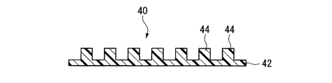
- a molded body 40 having a fine pattern 44 on the surface which is composed only of the cured product 42 having the surface to which the reverse pattern of the mold is transferred, is obtained.
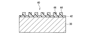
- a molded body 40 having a fine pattern 44 on the surface which is composed of a cured product 42 having a surface to which a reversal pattern of the mold is transferred, and the substrate 30 ( A laminate) is obtained.
- Examples of the molded article having a fine pattern on the surface include the following articles.
- Optical element microlens array, optical waveguide element, optical switching element (grid polarization element, wave plate, etc.), Fresnel zone plate element, binary element, blaze element, photonic crystal, etc.
- Antireflective member AR (Anti Reflection) coating member, etc.
- Chips biochip, micro-total analysis system ( ⁇ -TAS) chip, microreactor chip, etc. Others: recording media, display materials, catalyst carriers, filters, sensor members, resists used in the manufacture of semiconductor devices, daughter molds for nanoimprinting, etc.
- Transparent means that the transmittance is 90% or more and the scattering (haze value) is 1% or less in the visible light region.
- the refractive index of the cured product was determined as follows. A photocurable material is developed to a thickness of 100 ⁇ m with a doctor blade, and a high pressure mercury lamp (light source having dominant wavelengths at 255, 315, and 365 nm at 1.5 to 2.0 kHz) in an N 2 gas atmosphere. Was irradiated with light of 10 mW for 30 minutes to obtain a cured product. The cured product was carefully peeled off and the refractive index at a wavelength of 589 nm was measured at 23 ° C. with an Abbe refractive index measurement device (manufactured by ATAGO, 2T type) with a cutter knife having a size of 8 mm ⁇ 24 mm. .
- the transmittance and haze of the cured product were measured as follows. A photocurable material is filled between two synthetic quartz substrates (thickness: 1 mm, transmittance: 95%) with a spacer having a thickness of 20 ⁇ m interposed therebetween, and a high pressure mercury lamp (1.5-2. Light from a light source having a dominant wavelength at 255, 315, and 365 nm at 0 kHz was irradiated for 10 minutes at an output of 10 mW and cured. Using this as it was, the transmittance and haze were measured with the following apparatus. For comparison, two synthetic quartz substrates with only spacers interposed were used.
- the transmittance was judged to be good when it was 90% or higher at 400 nm and the haze was 1.0% or lower.
- Transmittance Spectrometer (Hitachi Ltd., U-4100), Haze: Haze meter (manufactured by Suga Test Instruments Co., Ltd., HGM-3K).
- the sensitivity of the photocurable material was determined as follows. A photocurable material is applied by spin coating so as to have a thickness of about 1.5 ⁇ m, from which a high pressure mercury lamp (light source having dominant wavelengths at 254, 315, and 365 nm at 1.5 to 2.0 kHz) is applied. The total amount of light until the film was completely cured was obtained and used as the sensitivity. Whether or not the photocurable material was completely cured was determined by measuring the IR spectrum and by the presence or absence of olefin absorption in the acrylic portion. The sensitivity was judged to be good when the value was 1000 mJ / cm 2 or less.
- the contact angle of the cured product with respect to water was measured as follows.
- the photocurable material was irradiated with light from a high-pressure mercury lamp (a light source having a dominant wavelength of 254, 315, and 365 nm at 1.5 to 2.0 kHz) for 15 seconds to obtain a cured product.
- the cured product was measured using a contact angle meter (CA-X150 type, manufactured by Kyowa Interface Science Co., Ltd.) by dropping 4 ⁇ L of water on the surface of the cured product according to JIS R3257.
- the contact angle is a measure of the releasability of the cured product. The contact angle was judged to be good when it was 75 degrees or more.
- the pKa of the compound (B) in the present invention is a value at 20 ° C.
- the pH of the 0.1 mol / L aqueous solution of the compound (B) is measured with a pH meter (C62, manufactured by AS ONE). Calculated from the measured values.
- a pH meter C62, manufactured by AS ONE.
- As the pH 7 standard solution a neutral phosphate standard solution according to JIS Z 8802 was used, and as the pH 4 standard solution, a phthalic acid standard solution according to JIS Z 8802 was used.
- the measurement temperature was 20 ° C.
- Compound (B) Compound (B-1): N-acetylcysteine, molecular weight: 163.2, pKa: 3.27.
- Inorganic fine particles (D) Dispersion of titanium oxide fine particles (D-1): manufactured by Ishihara Sangyo Co., Ltd., trade name: STS-01, average primary particle size: about 5 nm, titanium oxide content: 30.1% by mass, specific gravity: 1.322.
- Compound (f) Compound (f1-1): manufactured by Shin-Nakamura Chemical Co., Ltd., trade name: NPG (neopentyl glycol dimethacrylate).
- Photopolymerization initiator (G) Photopolymerization initiator (G-1): Ciba Geigy Specialty, trade name: Irgacure 651
- Example 1 In a vial container (internal volume 6 mL), 1.52 g of compound (f1-1), 0.88 g of compound (f2-2) and 1.44 g of compound (f3-1) were placed, and 0.2 ⁇ m of polyethylene Filtration through a filter made of terephthalate (hereinafter referred to as PTFE) gave a polymerizable component (F-1) (specific gravity: 1.05). 1.0 mL of the dispersion of titanium oxide fine particles (D-1) was diluted with 9.0 mL of water to obtain an aqueous dispersion of titanium oxide fine particles (D-1).
- PTFE polymerizable component
- MEK methyl ethyl ketone
- Example 1 The raw material charge ratio in Example 1 is shown in Table 1. Various evaluation was performed about the photocurable material (1). The results are shown in Table 2. From the results in Table 2, it was confirmed that the titanium oxide fine particles (D-1) were dispersed without being aggregated in the photocurable material (1).
- Example 2 In the same manner as in Example 1, polymerizable component (F-1) was obtained. 1.2 mL of the dispersion of zirconium oxide fine particles (D-2) was diluted with 3.8 mL of water to obtain an aqueous dispersion of zirconium oxide fine particles (D-2).
- Example 2 The raw material charge ratio in Example 2 is shown in Table 1. Various evaluation was performed about the photocurable material (2). The results are shown in Table 2. From the results in Table 2, it was confirmed that the zirconium oxide fine particles (D-2) were dispersed without being aggregated in the photocurable material (2).
- Example 3 In the same manner as in Example 1, polymerizable component (F-1) was obtained. 1.2 mL of the dispersion of fine titanium oxide particles (D-1) was diluted with 3.8 mL of water to obtain an aqueous dispersion of fine titanium oxide particles (D-1).
- the extract of the surface-modified inorganic fine particles (E′-3) was concentrated under reduced pressure while adding 200 ⁇ L of the polymerizable component (F-1), but as the concentration progressed, the fine particles aggregated and became opaque. Interrupted. In this method, the fine particles could not be stably dispersed in the polymerizable component (F-1).
- Example 4 In the same manner as in Example 1, an aqueous dispersion of titanium oxide fine particles (D-1) was obtained. 120 mg of compound (B-1) was placed in a container, and 3 mL of MEK was added and dissolved to obtain a solution of compound (B-1).
- the aqueous dispersion of the titanium oxide fine particles (D-1) and the solution of the compound (B-1) were stirred, mixed and allowed to stand, the mixture was separated into two phases, the upper phase being the MEK phase, The lower phase became the aqueous phase.
- the titanium oxide fine particles (D-1) were suspended as an opaque white solid between the upper phase and the lower phase. In this method, the titanium oxide fine particles (D-1) in the dispersion could not be extracted into the MEK phase.
- Example 5 In the same manner as in Example 1, an aqueous dispersion of titanium oxide fine particles (D-1) was obtained.
- Example 6 At 25 ° C., one drop of the photocurable material (1) of Example 1 was dropped on the silicon wafer to obtain a silicon wafer on which the material was uniformly applied. A quartz mold having a recess having a width of 800 nm, a depth of 180 nm, and a length of 10 ⁇ m on the surface was pressed against the photocurable material on the silicon wafer and pressed as it was at 0.5 MPa (gauge pressure).
- the photocurable material was irradiated with light from a high-pressure mercury lamp (a light source having a dominant wavelength at 255, 315, and 365 nm at 1.5 to 2.0 kHz) from the mold side for 15 seconds.
- a cured product of a photocurable material was obtained.
- the mold was separated from the silicon wafer to obtain a molded body in which a cured product having convex portions on the surface where the concave portions of the mold were inverted was formed on the surface of the silicon wafer.
- the height from the bottom surface to the top surface of the convex portion was 178 to 180 nm.
- Example 7 In the same manner as in Example 1, polymerizable component (F-1) was obtained. 0.95 mL of the dispersion of titanium oxide fine particles (D-1) was diluted with 9 mL of water to obtain an aqueous dispersion of titanium oxide fine particles (D-1).
- Example 7 The raw material charge ratio in Example 7 is shown in Table 1. Various evaluation was performed about the photocurable material (7). The results are shown in Table 2. From the results in Table 2, it was confirmed that the titanium oxide fine particles (D-1) were dispersed without being aggregated in the photocurable material (7).
- Example 8 In the same manner as in Example 1, polymerizable component (F-1) was obtained. 1.13 mL of the dispersion of zirconium oxide fine particles (D-2) was diluted with 3.9 mL of water to obtain an aqueous dispersion of zirconium oxide fine particles (D-2).
- Step (iii) The extract of the surface-modified inorganic fine particles (E-8) was concentrated under reduced pressure, 440 ⁇ L of the polymerizable component (F-1) was added in the middle, and further concentrated under reduced pressure to remove the solvent to obtain a translucent viscous liquid. 10 mg of the photopolymerization initiator (G-1) was added to obtain a photocurable material (8).
- the mass% of the zirconium oxide fine particles (D-2) in the photocurable material (8) is calculated as 37 masses when the total amount of the zirconium oxide fine particles (D-2) is transferred to the MEK phase in the step (ii). %Met.
- Example 8 The raw material charge ratio in Example 8 is shown in Table 1. Various evaluation was performed about the photocurable material (8). The results are shown in Table 2. From the results in Table 2, it was confirmed that the zirconium oxide fine particles (D-2) were dispersed without being aggregated in the photocurable material (8).
- Example 9 In the same manner as in Example 1, polymerizable component (F-1) was obtained. 9.8 mL of the dispersion of zirconium oxide fine particles (D-2) was diluted with 10.2 mL of water to obtain an aqueous dispersion of zirconium oxide fine particles (D-2).
- Step (iii) The extract of the surface-modified inorganic fine particles (E-9) was concentrated under reduced pressure, and 100 ⁇ L of the polymerizable component (F-1) was added along the way, and further concentrated under reduced pressure to remove the solvent to obtain a translucent viscous liquid. 15 mg of the photopolymerization initiator (G-1) was added to obtain a photocurable material (9). The mass% of the zirconium oxide fine particles (D-2) in the photocurable material (9) is calculated as 73 masses when the total amount of the zirconium oxide fine particles (D-2) is transferred to the MEK phase in the step (ii). %Met.
- Example 9 The raw material charge ratio in Example 9 is shown in Table 1. Various evaluation was performed about the photocurable material (9). The results are shown in Table 2. From the results in Table 2, it was confirmed that the zirconium oxide fine particles (D-2) were dispersed without being aggregated in the photocurable material (9).
- Example 10 7.23 mL of the dispersion of zirconium oxide fine particles (D-2) was diluted with 12.77 mL of water to obtain an aqueous dispersion of zirconium oxide fine particles (D-2).
- D-2 zirconium oxide fine particles
- C-10 solution of the surface modifier
- Step (iii) The extract of the surface-modified inorganic fine particles (E-10) was concentrated under reduced pressure, and 180 ⁇ L of the compound (f2-2) was added along the way, and further concentrated under reduced pressure to remove the solvent. 3 mg of the photopolymerization initiator (G-1) was added to obtain a photocurable material (10). The mass% of the zirconium oxide fine particles (D-2) in the photocurable material (10) is calculated as 60 mass when the total amount of the zirconium oxide fine particles (D-2) is transferred to the MEK phase in the step (ii). %Met.
- Example 10 The raw material charge ratio in Example 10 is shown in Table 1. Various evaluation was performed about the photocurable material (10). The results are shown in Table 2. From the results in Table 2, it was confirmed that the zirconium oxide fine particles (D-2) were dispersed without being aggregated in the photocurable material (10).
- Example 11 7.23 mL of the dispersion of zirconium oxide fine particles (D-2) was diluted with 12.77 mL of water to obtain an aqueous dispersion of zirconium oxide fine particles (D-2).
- Step (iii) The extract of the surface-modified inorganic fine particles (E-11) was concentrated under reduced pressure, and 164 ⁇ L of compound (f2-2) and 16 ⁇ L of compound (f2-3) were added along the way, and concentrated under reduced pressure to remove the solvent. A clear viscous liquid was obtained. 3 mg of the photopolymerization initiator (G-1) was added to obtain a photocurable material (11). The mass% of the zirconium oxide fine particles (D-2) in the photocurable material (11) is calculated as 60 mass when the total amount of the zirconium oxide fine particles (D-2) is transferred to the MEK phase in the step (ii). %Met.
- Example 11 The raw material charge ratios in Example 11 are shown in Table 1. Various evaluation was performed about the photocurable material (11). The results are shown in Table 2. From the results of Table 2, it was confirmed that the zirconium oxide fine particles (D-2) were dispersed without being aggregated in the photocurable material (11).
- Articles obtained using the photocurable material of the present invention include microlens arrays, optical waveguide elements, optical switching elements (grid polarizing elements, wave plates, etc.), Fresnel zone plate elements, binary elements, blazed elements, and photonics. It is useful as an optical element such as a crystal, an antireflection member, a production replica mold, or the like.
- Photocurable material 30
- Base material 40
- Molded body (article) 42
Abstract
Description
高屈折率化の手段としては、有機材料よりも屈折率が高い無機微粒子を、光硬化性材料中に分散させることが検討されている。 By the way, in applications of optical members (lens arrays, photonic crystals, etc.), the refractive index may be required to be 1.54 or more. Therefore, a high refractive index may be required for a cured product of the photocurable material.
As means for increasing the refractive index, it has been studied to disperse inorganic fine particles having a refractive index higher than that of an organic material in a photocurable material.
しかし、該方法で得られた無機微粒子は、硬化前の光硬化性材料への分散性はよいものの、光硬化性材料の硬化時に架橋に伴って押し出され、押し出された無機微粒子が析出または凝集し、硬化物の透明性を損なうことになる。 As a method for dispersing the inorganic fine particles in the photocurable material, a method is known in which the surface of the inorganic fine particles is modified with a compound having a high affinity with the photocurable material (Patent Document 3).
However, although the inorganic fine particles obtained by this method have good dispersibility in the photocurable material before curing, they are extruded along with crosslinking when the photocurable material is cured, and the extruded inorganic fine particles are precipitated or agglomerated. As a result, the transparency of the cured product is impaired.
該方法で修飾された無機微粒子は、光硬化性材料と同じ反応点を有するため、光硬化性材料の硬化時に分散状態のまま硬化物中に固定される。しかし、該方法では、無機微粒子を修飾する化合物が嵩高くなり、設計通りの屈折率が得られない、屈折率が低下する等の問題が生ずる。 As a method for maintaining the dispersion of the inorganic fine particles even when the photocurable material is cured, there is a method in which the inorganic fine particles modified with a compound having a high affinity are further modified with a compound having the same reactive site as the photocurable material. (Patent Document 4).
Since the inorganic fine particles modified by this method have the same reaction point as the photocurable material, they are fixed in the cured product in a dispersed state when the photocurable material is cured. However, in this method, the compound that modifies the inorganic fine particles becomes bulky, resulting in problems that the refractive index as designed cannot be obtained and the refractive index is lowered.
アクリル酸の分子量は小さいため、無機微粒子を修飾する化合物が嵩高くなく、一見よい方法のように見える。しかし、アクリル酸だけでは、無機微粒子の表面の極性を充分に覆いきれないため、アクリル酸で修飾された無機微粒子は、極性が比較的高い。そのため、下記のような問題が生ずる。 In order to introduce a reaction point with a photocurable material, a method of modifying inorganic fine particles with acrylic acid has been proposed (Non-Patent Document 1).
Since the molecular weight of acrylic acid is small, the compound that modifies the inorganic fine particles is not bulky and looks like a good method at first glance. However, since acrylic acid alone cannot sufficiently cover the polarity of the surface of the inorganic fine particles, the inorganic fine particles modified with acrylic acid have a relatively high polarity. Therefore, the following problems arise.
(2)また、分散させる対象の光硬化性材料も、比較的極性の高いもの(非フッ素系の(メタ)アクリレート類等)に限られてしまう。 (1) Since the inorganic fine particles are usually provided as an aqueous sol, it is necessary to extract from the aqueous sol with an organic solvent before adding the inorganic fine particles modified with acrylic acid to the photocurable material. However, inorganic fine particles modified with acrylic acid can be dispersed only in an organic solvent (such as methanol) having a relatively high polarity. Therefore, before extraction, filtration, solvent substitution, etc. are needed, and a process increases.
(2) Moreover, the photocurable material to be dispersed is also limited to those having relatively high polarity (such as non-fluorinated (meth) acrylates).
(i)(メタ)アクリロイルオキシ基を有する化合物(a)の1種以上からなる重合性成分(A)と、メルカプト基およびカルボキシ基を有する化合物(B)とを反応させ、前記化合物(B)に由来するカルボキシ基を末端に有する表面修飾剤(C)を得る工程。
(ii)無機微粒子(D)の表面を前記表面修飾剤(C)で修飾して、表面修飾無機微粒子(E)を得る工程。
(iii)前記表面修飾無機微粒子(E)と、(メタ)アクリロイルオキシ基を有する化合物(f)の1種以上からなる重合性成分(F)と、光重合開始剤(G)とを含む光硬化性材料を得る工程。 The method for producing a photocurable material of the present invention includes the following steps (i) to (iii).
(I) reacting a polymerizable component (A) comprising at least one compound (a) having a (meth) acryloyloxy group with a compound (B) having a mercapto group and a carboxy group, to thereby react the compound (B) A step of obtaining a surface modifying agent (C) having a carboxy group derived from the terminal.
(Ii) A step of obtaining the surface modified inorganic fine particles (E) by modifying the surface of the inorganic fine particles (D) with the surface modifier (C).
(Iii) Light containing the surface-modified inorganic fine particles (E), a polymerizable component (F) composed of one or more compounds (f) having a (meth) acryloyloxy group, and a photopolymerization initiator (G). Obtaining a curable material;
前記工程(ii)における無機微粒子(D)の質量が、前記工程(i)で用いた化合物(B)の質量の0.2~10倍であることが好ましい。
また、原料の仕込み割合の表示で、前記重合性成分(A)、前記化合物(B)、前記無機微粒子(D)、前記重合性成分(F)および前記光重合開始剤(G)の合計(100質量%)のうち、前記重合性成分(A)および前記重合性成分(F)の合計が、10~98.8質量%であり、前記化合物(B)が、0.01~28質量%であり、前記無機微粒子(D)が、0.1~75質量%であり、前記光重合開始剤(G)が、0.1~9質量%であることが好ましい。 The number of moles of the polymerizable component (A) in the step (i) is preferably 0.5 to 10 times the number of moles of the compound (B).
The mass of the inorganic fine particles (D) in the step (ii) is preferably 0.2 to 10 times the mass of the compound (B) used in the step (i).
In addition, the total of the polymerizable component (A), the compound (B), the inorganic fine particles (D), the polymerizable component (F), and the photopolymerization initiator (G) can be obtained by displaying the raw material charge ratio ( 100% by mass), the total of the polymerizable component (A) and the polymerizable component (F) is 10 to 98.8% by mass, and the compound (B) is 0.01 to 28% by mass. Preferably, the inorganic fine particles (D) are 0.1 to 75% by mass, and the photopolymerization initiator (G) is 0.1 to 9% by mass.
前記化合物(B)が、下記の条件(1)~(3)を満足することが好ましい。
条件(1):メルカプト基を1つ以上有する。
条件(2):カルボキシ基を1つ以上有する。
条件(3):1級アミノ基を有していない。 The pKa of the compound (B) is preferably 4.4 or less.
The compound (B) preferably satisfies the following conditions (1) to (3).
Condition (1): having one or more mercapto groups.
Condition (2): having one or more carboxy groups.
Condition (3): No primary amino group.
前記化合物(B)の分子量が、600以下であることが好ましい。 The compound (B) is an aliphatic carboxylic acid having 2 to 20 carbon atoms and has a mercapto group at least in any of the α-position, β-position and γ-position of the carboxyl group, and does not have a primary amino group. A compound is preferred.
The molecular weight of the compound (B) is preferably 600 or less.
前記金属酸化物が、酸化チタン、酸化ジルコニウム、酸化アルミニウム、チタン酸バリウム、酸化セリウム、酸化スズ、酸化亜鉛、酸化タンタル、酸化マンガン、酸化ニッケル、酸化鉄、酸化ケイ素、酸化ニオブ、酸化ランタンおよび酸化ガドリニウムからなる群から選ばれる1種以上であることが好ましい。
前記無機微粒子(D)の平均一次粒子径が、2~100nmであることが好ましい。 The inorganic fine particles (D) are preferably metal oxide fine particles.
The metal oxide is titanium oxide, zirconium oxide, aluminum oxide, barium titanate, cerium oxide, tin oxide, zinc oxide, tantalum oxide, manganese oxide, nickel oxide, iron oxide, silicon oxide, niobium oxide, lanthanum oxide and oxidation. It is preferably at least one selected from the group consisting of gadolinium.
The average primary particle diameter of the inorganic fine particles (D) is preferably 2 to 100 nm.
前記重合性成分(F)が、(メタ)アクリロイルオキシ基を2つ以上有する化合物(f1)(ただし、化合物(f2)を除く。)、フッ素原子を有し、かつ(メタ)アクリロイルオキシ基を1つ以上有する化合物(f2)および(メタ)アクリロイルオキシ基を1つ有する化合物(f3)(ただし、化合物(f2)を除く。)からなり、前記化合物(f1)、前記化合物(f2)および前記化合物(f3)の合計(100質量%)のうち、前記化合物(f1)が、15~70質量%であり、前記化合物(f2)が、5~45質量%であり、前記化合物(f3)が、10~65質量%であることが好ましい。 The polymerizable component (F) preferably contains a compound (f2) having a fluorine atom and having one or more (meth) acryloyloxy groups.
The polymerizable component (F) is a compound (f1) having two or more (meth) acryloyloxy groups (excluding the compound (f2)), a fluorine atom, and a (meth) acryloyloxy group. The compound (f2) and the compound (f3) having one (meth) acryloyloxy group (excluding the compound (f2)), wherein the compound (f1), the compound (f2) and the compound Of the total (100% by mass) of the compound (f3), the compound (f1) is 15 to 70% by mass, the compound (f2) is 5 to 45% by mass, and the compound (f3) is It is preferably 10 to 65% by mass.
前記重合性成分(A)が、前記重合性成分(F)と同一の重合性成分であることが好ましい。 The polymerizable component (A) is preferably composed of one or more of the compounds (f) constituting the polymerizable component (F).
It is preferable that the polymerizable component (A) is the same polymerizable component as the polymerizable component (F).
本発明の光硬化性材料は、実質的に溶媒を含まないことが好ましい。
本発明の物品は、本発明の光硬化性材料を硬化してなるもの、または、基材の表面に、本発明の光硬化性材料を硬化してなる硬化膜を有するものであることを特徴とする。 The photocurable material of the present invention is obtained by the production method of the present invention.
The photocurable material of the present invention preferably contains substantially no solvent.
The article of the present invention is a product obtained by curing the photocurable material of the present invention, or has a cured film formed by curing the photocurable material of the present invention on the surface of a substrate. And
本発明の光硬化性材料は、透明性の高い高屈折率の硬化物を形成できる。
本発明の物品は、透明性および屈折率が高い。 According to the method for producing a photocurable material of the present invention, a photocurable material capable of forming a cured product having a high transparency and a high refractive index can be easily produced.
The photocurable material of the present invention can form a cured product having high transparency and high transparency.
The article of the present invention has high transparency and refractive index.
本発明の光硬化性材料の製造方法は、下記の工程(i)~(iii)を有する方法である。
(i)(メタ)アクリロイルオキシ基を有する化合物(a)の1種以上からなる重合性成分(A)と、メルカプト基およびカルボキシ基を有する化合物(B)とを反応させ、化合物(B)に由来するカルボキシ基を末端に有する表面修飾剤(C)を得る工程。
(ii)無機微粒子(D)の表面を表面修飾剤(C)で修飾して、表面修飾無機微粒子(E)を得る工程。
(iii)表面修飾無機微粒子(E)と、(メタ)アクリロイルオキシ基を有する化合物(f)の1種以上からなる重合性成分(F)と、光重合開始剤(G)とを含む光硬化性材料を得る工程。 <Method for producing photocurable material>
The method for producing a photocurable material of the present invention is a method having the following steps (i) to (iii).
(I) A polymerizable component (A) composed of one or more compounds (a) having a (meth) acryloyloxy group is reacted with a compound (B) having a mercapto group and a carboxy group to give the compound (B) The process of obtaining the surface modifier (C) which has the carboxy group derived from the terminal.
(Ii) A step of modifying the surface of the inorganic fine particles (D) with the surface modifier (C) to obtain surface-modified inorganic fine particles (E).
(Iii) Photocuring comprising surface-modified inorganic fine particles (E), a polymerizable component (F) composed of one or more compounds (f) having a (meth) acryloyloxy group, and a photopolymerization initiator (G). A step of obtaining a functional material.
工程(i)は、重合性成分(A)と化合物(B)とを反応させ、化合物(B)に由来するカルボキシ基を末端に有する表面修飾剤(C)を得る工程である。 Step (i):
Step (i) is a step of reacting the polymerizable component (A) with the compound (B) to obtain a surface modifier (C) having a carboxy group derived from the compound (B) at the terminal.
重合性成分(A)は、化合物(a)の1種以上からなる重合性成分である。
化合物(a)は、(メタ)アクリロイルオキシ基を有する化合物であり、後述する化合物(f)として例示するものと同様のものが挙げられる。 (Polymerizable component (A))
The polymerizable component (A) is a polymerizable component composed of one or more compounds (a).
The compound (a) is a compound having a (meth) acryloyloxy group, and examples thereof include those exemplified as the compound (f) described later.
化合物(B)は、メルカプト基およびカルボキシ基を有する化合物である。
メルカプト基は、重合性成分(A)の(メタ)アクリロイルオキシ基の炭素-炭素不飽和二重結合と反応する。これにより、無機微粒子(D)と結合できる化合物(B)に由来するカルボキシ基と、重合性成分(F)との親和性が高く、かつ重合性成分(F)との反応点となる重合性成分(A)に由来する構造とを有する表面修飾剤(C)が得られる。また、工程(i)において未反応のメルカプト基であっても、重合性成分(F)との反応点となる。 (Compound (B))
The compound (B) is a compound having a mercapto group and a carboxy group.
The mercapto group reacts with the carbon-carbon unsaturated double bond of the (meth) acryloyloxy group of the polymerizable component (A). Thereby, the high affinity of the carboxy group derived from the compound (B) capable of binding to the inorganic fine particles (D) and the polymerizable component (F), and the polymerizable property serving as a reaction point between the polymerizable component (F). A surface modifier (C) having a structure derived from the component (A) is obtained. Moreover, even if it is an unreacted mercapto group in the step (i), it becomes a reaction point with the polymerizable component (F).
なお、本発明における化合物(B)のpKaは、20℃において、化合物(B)の水溶液のpHを測定し、該測定値から算出した値である。 The compound (B) preferably has a pKa of 4.4 or less. In the present invention, the surface modification inorganic fine particles (E) are obtained by modifying the inorganic fine particles (D) using the surface modifier (C) having a carboxy group derived from the compound (B) at the terminal. At this time, it is preferable that the carboxy group of the surface modifier (C) is sufficiently dissociated. When the pKa of the compound (B) is 4.4 or less, the carboxy group of the surface modifier (C) is sufficiently dissociated and the modification of the inorganic fine particles (D) proceeds smoothly. The lower limit value of the pKa of the compound (B) is not particularly limited, but for reasons such as the type of compounds that are usually available and the durability of the cured product of the photocurable material obtained by the present invention, − 2 is preferred and 0 is particularly preferred. Therefore, the pKa range of the compound (B) is preferably −2 to 4.4, and particularly preferably 0 to 4.3.
The pKa of the compound (B) in the present invention is a value calculated from the measured value by measuring the pH of the aqueous solution of the compound (B) at 20 ° C.
条件(1):メルカプト基を1つ以上有する。
条件(2):カルボキシ基を1つ以上有する。
条件(3):1級アミノ基を有していない。 As the compound (B), from the viewpoint of the binding property of the surface modifier (C) to the inorganic fine particles (D) and the dispersibility of the surface modified inorganic fine particles (E) in the polymerizable component (F), the following conditions ( Compounds satisfying 1) to (3) are preferred.
Condition (1): having one or more mercapto groups.
Condition (2): having one or more carboxy groups.
Condition (3): No primary amino group.
N-アセチルアミノ基等のN-アシルアミノ基、2級アミノ基、3級アミノ基、4級アンモニウム基、イミノ基、ハロゲン原子、アルコキシ基、水酸基、ホルミル基、ケト基、カルボキシ基、酸塩化物、エステル基、アミド基、シアノ基、ニトロソ基、ニトロ基、アルケニル基、アルキニル基、アリール基、フェニル基、シクロアルキル基、複素環基、チオエーテル基、メルカプト基、スルホニル基、Fmoc(9-フルオレニルメチルオキシカルボニル)基等。
これらのうち、ハロゲン原子、ケト基、カルボキシ基、シアノ基、ニトロ基など、一般的に電子吸引的な性質を有すると解される置換基が好ましいが、他の置換基と、N-アシルアミノ基の組合せや置換位置等により、化合物(B)のカルボキシル基が、無機微粒子(D)の修飾のために適切な解離状態を取れる範囲において、一般的に電子供与的な性質を有すると解される基も適宜組み合わせることができる。
なお、置換基がメルカプト基の場合、該メルカプト基をもって条件(1)も同時に満たしているとしてもよい。 As a substituent, what has the following functional groups or this functional group is mentioned, for example.
N-acylamino group such as N-acetylamino group, secondary amino group, tertiary amino group, quaternary ammonium group, imino group, halogen atom, alkoxy group, hydroxyl group, formyl group, keto group, carboxy group, acid chloride Ester group, amide group, cyano group, nitroso group, nitro group, alkenyl group, alkynyl group, aryl group, phenyl group, cycloalkyl group, heterocyclic group, thioether group, mercapto group, sulfonyl group, Fmoc (9-full (Oleenylmethyloxycarbonyl) group and the like.
Of these, halogen atoms, keto groups, carboxy groups, cyano groups, nitro groups and the like, which are generally understood to have electron-withdrawing properties, are preferred, but other substituents and N-acylamino groups It is understood that the carboxyl group of the compound (B) generally has an electron-donating property within a range in which the carboxyl group of the compound (B) can take an appropriate dissociation state for the modification of the inorganic fine particles (D), depending on the combination and the substitution position of Groups can also be combined as appropriate.
When the substituent is a mercapto group, the mercapto group may satisfy the condition (1) at the same time.
該脂肪族カルボン酸の、カルボキシル基を除いた部位構造は、直鎖構造であっても分岐構造であってもよい。また、不飽和結合を含んでいてもよい。該部位としては、直鎖または分岐構造の脂肪族飽和炭化水素基であることが好ましい。また、該脂肪族カルボン酸は、前記のように置換基を有していてもよい。化合物(B)としては、アミノ基がアシル基で置換されたシステイン誘導体も好ましい。 Further, the compound (B) is an aliphatic carboxylic acid having 2 to 20 carbon atoms, having a mercapto group at least in any of the α-position, β-position and γ-position of the carboxyl group, and having a primary amino group. Preferably, the compound is not. Here, the “carbon number” is a number including carbon atoms in the carboxyl group (—COOH).
The site structure of the aliphatic carboxylic acid excluding the carboxyl group may be a linear structure or a branched structure. Moreover, the unsaturated bond may be included. The site is preferably a linear or branched aliphatic saturated hydrocarbon group. The aliphatic carboxylic acid may have a substituent as described above. As the compound (B), a cysteine derivative in which an amino group is substituted with an acyl group is also preferable.
N-プロピオニルシステイン(177.2)、
N-ブタノイルシステイン(191.3)、
N-ヘキサノイルシステイン(219.3)、
N-オクタノイルシステイン(247.4)、
N-デカノイルシステイン(275.4)、
N-ドデカノイルシステイン(303.5)、
N-テトラデカノイルシステイン(331.5)、
N-ヘキサデカノイルシステイン(359.6)、
N-オクタデカノイルシステイン(387.6)、
N-アセチルホモシステイン(177.2)、
アセチルアミノメルカプト酢酸(149.2)、
Fmoc-システイン(343.4)、
Fmoc-S-トリチルシステイン(585.7)、
Fmoc-S-ベンジルシステイン(433.5)、
N-メチルシステイン(135.2)、
N,N-ジメチルシステイン(149.2)、
2-エチルアミノ-3-メルカプトプロピオン酸(149.2)、
2-プロピルアミノ-3-メルカプトプロピオン酸(163.2)、
チオグリコール酸(92.1)、
2-メルカプトプロピオン酸(106.1)、
2-メルカプト酪酸(120.2)、
2-メルカプト-3-メチル酪酸(134.2)、
2-メルカプトペンタン酸(134.2)、
2-メルカプト-3-メチルペンタン酸(148.2)、
2-メルカプト-4-メチルペンタン酸(148.2)、
2-メルカプトヘキサン酸(148.2)、
2-メルカプト-3-メチルヘキサン酸(162.3)、
2-メルカプトヘプタン酸(162.3)、
2-メルカプトオクタン酸(176.3)、
2-メルカプトノナン酸(190.3)、
2-メルカプトデカン酸(204.3)、
2-メルカプトウンデカン酸(218.4)、
2-メルカプトドデカン酸(232.4)、
2-メルカプトテトラデカン酸(260.4)、
2-メルカプトヘキサデカン酸(288.5)、
2-メルカプトオクタデカン酸(316.5)、
2,3-ジメルカプトプロピオン酸(138.2)、
2,3-ジメルカプトコハク酸(188.2)、
2-フルオロ-3-メルカプトプロピオン酸(124.1)、
2-クロロ-3-メルカプトプロピオン酸(140.6)、
2-ブロモ-3-メルカプトプロピオン酸(185.0)、
2-アイオド-3-メルカプトプロピオン酸(232)、
2-ヒドロキシ-3-メルカプトプロピオン酸(122.1)、
2-ヒドロキシ-4-メルカプト酪酸(136.2)、
2-フェニル-3-メルカプトプロピオン酸(182.2)、
3-アセチルアミノ-3-メルカプトプロピオン酸(163.2)、
N-メトキシカルボニルシステイン(179.2)、
N-エトキシカルボニルシステイン(193.2)、
N-カルボキシシステイン(165.2)、
3-メルカプトプロピオン酸(106.1)、
3-メルカプト酪酸(120.2)、
3-メルカプト-2-メチル酪酸(134.2)、
3-メルカプトペンタン酸(134.2)、
3-メルカプト-4-メチルペンタン酸(148.2)、
3-メルカプトヘキサン酸(148.2)、
3-メルカプトノナン酸(190.3)、
3-メルカプトデカン酸(204.3)、
2-メルカプトコハク酸(150.2)、
2-メルカプトメチルコハク酸(164.2)、
2-メルカプトマロン酸(136.1)、
3-ヒドロキシ-4-メルカプト酪酸(136.2)、
2-メルカプト安息香酸(154.2)、
3-メルカプト安息香酸(154.2)、
4-メルカプト安息香酸(154.2)、
テトラフルオロ-4-メルカプト安息香酸(226.15)、
2-メルカプトメチル安息香酸(168.2)、
3-メルカプトメチル安息香酸(168.2)、
4-メルカプトメチル安息香酸(168.2)、
2-メルカプトフェニル酢酸(168.2)、
3-メルカプトフェニル酢酸(168.2)、
4-メルカプトフェニル酢酸(168.2)、
2-メルカプトメチルフェニル酢酸(182.2)、
3-メルカプトメチルフェニル酢酸(182.2)、
4-メルカプトメチルフェニル酢酸(182.2)、
α-メルカプトメチルフェニル酢酸(182.2)等。 N-acetylcysteine (163.2),
N-propionylcysteine (177.2),
N-butanoylcysteine (191.3),
N-hexanoylcysteine (219.3),
N-octanoylcysteine (247.4),
N-decanoylcysteine (275.4),
N-dodecanoylcysteine (303.5),
N-tetradecanoylcysteine (331.5),
N-hexadecanoylcysteine (359.6),
N-octadecanoylcysteine (387.6),
N-acetylhomocysteine (177.2),
Acetylaminomercaptoacetic acid (149.2),
Fmoc-cysteine (343.4),
Fmoc-S-tritylcysteine (585.7),
Fmoc-S-benzylcysteine (433.5),
N-methylcysteine (135.2),
N, N-dimethylcysteine (149.2),
2-ethylamino-3-mercaptopropionic acid (149.2),
2-propylamino-3-mercaptopropionic acid (163.2),
Thioglycolic acid (92.1),
2-mercaptopropionic acid (106.1),
2-mercaptobutyric acid (120.2),
2-mercapto-3-methylbutyric acid (134.2),
2-mercaptopentanoic acid (134.2),
2-mercapto-3-methylpentanoic acid (148.2),
2-mercapto-4-methylpentanoic acid (148.2),
2-mercaptohexanoic acid (148.2),
2-mercapto-3-methylhexanoic acid (162.3),
2-mercaptoheptanoic acid (162.3),
2-mercaptooctanoic acid (176.3),
2-mercaptononanoic acid (190.3),
2-mercaptodecanoic acid (204.3),
2-mercaptoundecanoic acid (218.4),
2-mercaptododecanoic acid (232.4),
2-mercaptotetradecanoic acid (260.4),
2-mercaptohexadecanoic acid (288.5),
2-mercaptooctadecanoic acid (316.5),
2,3-dimercaptopropionic acid (138.2),
2,3-dimercaptosuccinic acid (188.2),
2-fluoro-3-mercaptopropionic acid (124.1),
2-chloro-3-mercaptopropionic acid (140.6),
2-bromo-3-mercaptopropionic acid (185.0),
2-iodo-3-mercaptopropionic acid (232),
2-hydroxy-3-mercaptopropionic acid (122.1),
2-hydroxy-4-mercaptobutyric acid (136.2),
2-phenyl-3-mercaptopropionic acid (182.2),
3-acetylamino-3-mercaptopropionic acid (163.2),
N-methoxycarbonylcysteine (179.2),
N-ethoxycarbonylcysteine (193.2),
N-carboxycysteine (165.2),
3-mercaptopropionic acid (106.1),
3-mercaptobutyric acid (120.2),
3-mercapto-2-methylbutyric acid (134.2),
3-mercaptopentanoic acid (134.2),
3-mercapto-4-methylpentanoic acid (148.2),
3-mercaptohexanoic acid (148.2),
3-mercaptononanoic acid (190.3),
3-mercaptodecanoic acid (204.3),
2-mercaptosuccinic acid (150.2),
2-mercaptomethyl succinic acid (164.2),
2-mercaptomalonic acid (136.1),
3-hydroxy-4-mercaptobutyric acid (136.2),
2-mercaptobenzoic acid (154.2),
3-mercaptobenzoic acid (154.2),
4-mercaptobenzoic acid (154.2),
Tetrafluoro-4-mercaptobenzoic acid (226.15),
2-mercaptomethylbenzoic acid (168.2),
3-mercaptomethylbenzoic acid (168.2),
4-mercaptomethylbenzoic acid (168.2),
2-mercaptophenylacetic acid (168.2),
3-mercaptophenylacetic acid (168.2),
4-mercaptophenylacetic acid (168.2),
2-mercaptomethylphenylacetic acid (182.2),
3-mercaptomethylphenylacetic acid (182.2),
4-mercaptomethylphenylacetic acid (182.2),
α-mercaptomethylphenylacetic acid (182.2) and the like.
表面修飾剤(C)は、重合性成分(A)と化合物(B)とを反応させて得られる。
該反応は、重合性成分(A)の有する(メタ)アクリロイルオキシ基の炭素-炭素不飽和二重結合と化合物(B)の有するメルカプト基との反応、すなわちエン-チオール反応である。
重合性成分(A)と化合物(B)とを反応させる理由は、下記の通りである。 (Surface modifier (C))
The surface modifier (C) is obtained by reacting the polymerizable component (A) with the compound (B).
This reaction is a reaction between the carbon-carbon unsaturated double bond of the (meth) acryloyloxy group of the polymerizable component (A) and the mercapto group of the compound (B), that is, an ene-thiol reaction.
The reason for reacting the polymerizable component (A) and the compound (B) is as follows.
該反応は、完全に行う必要はなく、未反応物が残存していてもよい。また、重合性成分(A)の一部が重合して得られた重合物の末端に化合物(B)が反応してもよい。 This reaction is performed, for example, by dissolving the compound (B) in an organic solvent, adding a polymerizable component (A) and a photopolymerization initiator to the compound, and irradiating with light.
The reaction does not have to be performed completely, and unreacted substances may remain. Further, the compound (B) may react with the terminal of a polymer obtained by polymerizing a part of the polymerizable component (A).
光重合開始剤の添加量は、重合性成分(A)および化合物(B)の合計100質量部に対して、0.1~5質量部が好ましい。 As a photoinitiator, the thing similar to what is illustrated as a photoinitiator (G) mentioned later is mentioned.
The addition amount of the photopolymerization initiator is preferably 0.1 to 5 parts by mass with respect to 100 parts by mass in total of the polymerizable component (A) and the compound (B).
光の照射時間は、たとえば、10mWの照射密度であれば、1分~3時間である。
工程(i)における反応は、2段階以上に分けて行ってもよい。 The kind of light should just be selected suitably according to a photoinitiator, for example, the ultraviolet-ray which has a dominant wavelength in 365 nm is mentioned.
The light irradiation time is, for example, 1 minute to 3 hours for an irradiation density of 10 mW.
The reaction in step (i) may be performed in two or more stages.
工程(ii)は、無機微粒子(D)の表面を表面修飾剤(C)で修飾して、表面修飾無機微粒子(E)を得る工程である。 Step (ii):
Step (ii) is a step of obtaining the surface-modified inorganic fine particles (E) by modifying the surface of the inorganic fine particles (D) with the surface modifier (C).
無機微粒子(D)としては、金属酸化物の微粒子が好ましい。
金属酸化物としては、周期表4族に属する金属、周期表13族に属する金属、および周期表14族に属する金属からなる群から選ばれる少なくとも1種の金属の酸化物が挙げられる。
周期表4族に属する金属としては、Ti、Zr、Hf等が挙げられる。
周期表13族に属する金属としては、Al、Ga、In等が挙げられる。
周期表14族に属する金属としては、Si、Ge、Sn、Pb等が挙げられる。 (Inorganic fine particles (D))
As the inorganic fine particles (D), metal oxide fine particles are preferable.
Examples of the metal oxide include oxides of at least one metal selected from the group consisting of metals belonging to Group 4 of the periodic table, metals belonging to Group 13 of the periodic table, and metals belonging to Group 14 of the periodic table.
Examples of metals belonging to Group 4 of the periodic table include Ti, Zr, and Hf.
Examples of the metal belonging to Group 13 of the periodic table include Al, Ga, and In.
Examples of metals belonging to Group 14 of the periodic table include Si, Ge, Sn, and Pb.
無機微粒子(D)の平均一次粒子径は、分散液の状態にて動的散乱法で測定される。 The average primary particle diameter of the inorganic fine particles (D) is preferably 2 nm to 100 nm, more preferably 4 nm to 60 nm. If the average primary particle diameter is 100 nm or less, the transparency of the cured product in the visible light region can be maintained. When the average primary particle diameter is 2 nm or more, an increase in the necessary amount of the compound (B) accompanying the enlargement of the total specific surface area of the fine particles can be avoided.
The average primary particle diameter of the inorganic fine particles (D) is measured by a dynamic scattering method in a dispersion state.
無機微粒子(D)は、1種を単独で用いてもよく、2種以上を併用してもよく、2種以上から構成される複合金属酸化物の微粒子であってもよい。 Since the crystal structure of the metal oxide fine particles is broken at the interface, part or all of the metal oxide fine particles may be hydroxides.
The inorganic fine particles (D) may be used alone or in combination of two or more, or may be fine particles of a composite metal oxide composed of two or more.
水系分散液中の無機微粒子(D)の濃度は、1~35質量%が好ましく、2~20質量%がより好ましい。濃度が薄すぎると、水系分散液からの表面修飾無機微粒子(E)の抽出効率が悪くなる。濃度が濃すぎると、水系分散液から表面修飾無機微粒子(E)を抽出する際にかかる機械的ストレスにより、水系分散液中で無機微粒子(D)が凝集を起こしてしまう。 Examples of the form of the inorganic fine particles (D) include a powder, a dispersion (sol) dispersed in a solvent (dispersion medium), and the dispersion is preferable from the viewpoint of the transparency of the cured product. An aqueous dispersion that is water is more preferred.
The concentration of the inorganic fine particles (D) in the aqueous dispersion is preferably 1 to 35% by mass, more preferably 2 to 20% by mass. If the concentration is too thin, the extraction efficiency of the surface-modified inorganic fine particles (E) from the aqueous dispersion is deteriorated. When the concentration is too high, the inorganic fine particles (D) are aggregated in the aqueous dispersion due to mechanical stress applied when the surface-modified inorganic fine particles (E) are extracted from the aqueous dispersion.
表面修飾無機微粒子(E)は、無機微粒子(D)の表面を表面修飾剤(C)で修飾して得られる。該修飾は、たとえば、水への溶解度の低い有機溶媒に表面修飾剤(C)を溶解した溶液と、無機微粒子(D)の水系ゾルとを混合し、表面修飾無機微粒子(E)を有機溶媒に抽出することによって行われる。 (Surface modified inorganic fine particles (E))
The surface-modified inorganic fine particles (E) are obtained by modifying the surface of the inorganic fine particles (D) with the surface modifier (C). The modification is performed, for example, by mixing a solution obtained by dissolving the surface modifier (C) in an organic solvent having low solubility in water and an aqueous sol of inorganic fine particles (D), and then modifying the surface modified inorganic fine particles (E) into the organic solvent. Is done by extracting.
該抽出液が水を含む場合、ヘキサン等の疎水性の高い有機溶媒を、該抽出液に添加することで、該抽出液に溶け込んだ水をさらに除去できる。 After extracting the inorganic fine particles (D), the aqueous solvent is removed by a known method such as decantation or a separatory funnel to obtain an extract of the surface-modified inorganic fine particles (E).
When the extract contains water, the water dissolved in the extract can be further removed by adding a highly hydrophobic organic solvent such as hexane to the extract.
重合性成分(F)と親和性の高い重合性成分(A)に由来する構造を無機微粒子(D)の表面に導入したわけであるから、多少なりとも親和性の劣る溶媒は、できるだけ残存していないほうが、表面修飾無機微粒子(E)の抽出液の一時保管する際、または、工程(iii)にて重合性成分(F)を混合する際に、相分離や表面修飾無機微粒子(E)の凝集を抑制できる。減圧留去の際に、メタノール、エタノール等のアルコールを少量添加すると水が共沸するため、さらに好ましい。 It is preferable that the extract is concentrated by a known method such as distillation under reduced pressure before the step (iii) described later or is substantially free of solvent. The reason is as follows.
Since a structure derived from the polymerizable component (A) having a high affinity with the polymerizable component (F) is introduced on the surface of the inorganic fine particles (D), a solvent having a somewhat lower affinity remains as much as possible. When the extract of the surface-modified inorganic fine particles (E) is temporarily stored or when the polymerizable component (F) is mixed in the step (iii), the phase separation or the surface-modified inorganic fine particles (E) Aggregation can be suppressed. It is more preferable to add a small amount of alcohol such as methanol or ethanol during the distillation under reduced pressure because water azeotropes.
工程(iii)は、表面修飾無機微粒子(E)と重合性成分(F)と光重合開始剤(G)とを含む光硬化性材料を得る工程である。 Step (iii):
Step (iii) is a step of obtaining a photocurable material containing the surface-modified inorganic fine particles (E), the polymerizable component (F), and the photopolymerization initiator (G).
重合性成分(F)は、(メタ)アクリロイルオキシ基を有する化合物(f)の1種以上からなる重合性成分である。化合物(f)は、1種を単独で用いてもよく、2種以上を併用してもよい。
重合性成分(F)としては、硬化物の離型性、機械的強度、透明性の点から、化合物(f1)、化合物(f2)および化合物(f3)の3種の組み合わせが好ましい。 (Polymerizable component (F))
The polymerizable component (F) is a polymerizable component comprising at least one compound (f) having a (meth) acryloyloxy group. A compound (f) may be used individually by 1 type, and may use 2 or more types together.
As the polymerizable component (F), three types of combinations of the compound (f1), the compound (f2), and the compound (f3) are preferable from the viewpoint of releasability, mechanical strength, and transparency of the cured product.
化合物(f1)としては、ビスフェノール類の(メタ)アクリレート、フルオレン骨格を有する(メタ)アクリレート、ナフタレン骨格を有する(メタ)アクリレート、グリコール類等のジオールの(メタ)アクリレート、グリセロールやトリメチロール等のトリオール類の(メタ)アクリレート、およびペンタエリスリトール等のテトラオールの(メタ)アクリレートが挙げられ、ジオールの(メタ)アクリレート、トリオール類の(メタ)アクリレート、およびテトラオールの(メタ)アクリレートが好ましい。 Compound (f1) is a compound having two or more (meth) acryloyloxy groups (excluding compound (f2)). The number of (meth) acryloyloxy groups in the compound (f1) is preferably from 2 to 10, particularly preferably from 2 to 6.
Examples of the compound (f1) include (meth) acrylates of bisphenols, (meth) acrylates having a fluorene skeleton, (meth) acrylates having a naphthalene skeleton, (meth) acrylates of diols such as glycols, glycerol and trimethylol Examples include (meth) acrylates of triols and (meth) acrylates of tetraols such as pentaerythritol, (meth) acrylates of diols, (meth) acrylates of triols, and (meth) acrylates of tetraols are preferred.
ビスフェノールAジ(メタ)アクリレート、変性ビスフェノールAジ(メタ)アクリレート(エトキシ化ビスフェノールAジ(メタ)アクリレート、プロポキシ化ビスフェノールAジ(メタ)アクリレート、プロポキシ化エトキシ化ビスフェノールAジ(メタ)アクリレート、ビスフェノールAグリセロレートジ(メタ)アクリレート、ビスフェノールAプロポキシレートグリセロレートジ(メタ)アクリレート等。)、エトキシ化ビスフェノールFジ(メタ)アクリレート、フルオレンジ(メタ)アクリレート、トリシクロデカンジメタノールジ(メタ)アクリレート、エチレングリコールジ(メタ)アクリレート、ジプロピレングリコールジ(メタ)アクリレート、1,3-ブタンジオールジ(メタ)アクリレート、1,4-ブタンジオールジ(メタ)アクリレート、グリセロール1,3-ジグリセロレートジ(メタ)アクリレート、1,6-ヘキサンジオールエトキシレートジ(メタ)アクリレート、1,6-ヘキサンジオールプロポキシレートジ(メタ)アクリレート、1,6-ヘキサンジオールジ(メタ)アクリレート、3-ヒドロキシ-2,2-ジメチルプロピオネートジ(メタ)アクリレート、1,9-ノナンジオールジ(メタ)アクリレート、1,10-デカンジオールジ(メタ)アクリレート、ジエチレングリコールジ(メタ)アクリレート、ネオペンチルグリコールジ(メタ)アクリレート、ネオペンチルグリコールプロポキシレートジ(メタ)アクリレート、ポリエチレングリコールジ(メタ)アクリレート、プロピレングリコールジ(メタ)アクリレート、グリセロールジ(メタ)アクリレート、プロピレングリコールグリセロレートジ(メタ)アクリレート、ポリプロピレングリコールジ(メタ)アクリレート、ポリオキシエチレングリコールジ(メタ)アクリレート、トリプロピレングリコールジ(メタ)アクリレート、トリエチレングリコールジ(メタ)アクリレート、テトラエチレングリコールジ(メタ)アクリレート、トリプロピレングリコールグリセロレートジ(メタ)アクリレート、2-ヒドロキシ-3-アクリロイルオキシプロピル(メタ)アクリレート、2-メチル-1,3-プロパンジオールジアクリレート、トリメチロールプロパンベンゾエートジ(メタ)アクリレート、ペンタエリスリトールジ(メタ)アクリレートモノステアリル酸、トリメチロールプロパンエトキシレートメチルエーテルジ(メタ)アクリレート。
また、ジウレタンジ(メタ)アクリレート、ウレタン結合を二つ以上有する質量平均分子量400以上1600未満かつ25℃における粘度が20Pa・s以下である(メタ)アクリロイルオキシ基を2つ以上有するウレタンモノマーもしくはオリゴマー等のウレタン結合を有するモノマーや、1,3-ビス(3-メタクリロイロキシプロピル)-1,1,3,3-テトラメチルジシロキサンのような、ケイ素原子を含むモノマーも採用できる。 Examples of the compound (f1) include the following compounds.
Bisphenol A di (meth) acrylate, modified bisphenol A di (meth) acrylate (ethoxylated bisphenol A di (meth) acrylate, propoxylated bisphenol A di (meth) acrylate, propoxylated ethoxylated bisphenol A di (meth) acrylate, bisphenol A glycerolate di (meth) acrylate, bisphenol A propoxylate glycerolate di (meth) acrylate, etc.), ethoxylated bisphenol F di (meth) acrylate, full orange (meth) acrylate, tricyclodecane dimethanol di (meth) Acrylate, ethylene glycol di (meth) acrylate, dipropylene glycol di (meth) acrylate, 1,3-butanediol di (meth) acrylate, 1,4-butanedio Rudi (meth) acrylate, glycerol 1,3-diglycerolate di (meth) acrylate, 1,6-hexanediol ethoxylate di (meth) acrylate, 1,6-hexanediol propoxylate di (meth) acrylate, 1, 6-hexanediol di (meth) acrylate, 3-hydroxy-2,2-dimethylpropionate di (meth) acrylate, 1,9-nonanediol di (meth) acrylate, 1,10-decanediol di (meth) Acrylate, diethylene glycol di (meth) acrylate, neopentyl glycol di (meth) acrylate, neopentyl glycol propoxylate di (meth) acrylate, polyethylene glycol di (meth) acrylate, propylene glycol di (meth) acrylate Glycerol di (meth) acrylate, propylene glycol glycerolate di (meth) acrylate, polypropylene glycol di (meth) acrylate, polyoxyethylene glycol di (meth) acrylate, tripropylene glycol di (meth) acrylate, triethylene glycol di (meta) ) Acrylate, tetraethylene glycol di (meth) acrylate, tripropylene glycol glycerolate di (meth) acrylate, 2-hydroxy-3-acryloyloxypropyl (meth) acrylate, 2-methyl-1,3-propanediol diacrylate, Trimethylolpropane benzoate di (meth) acrylate, pentaerythritol di (meth) acrylate monostearyl acid, trimethylolpropane ethoxy Rate methyl ether di (meth) acrylate.
Further, diurethane di (meth) acrylate, urethane monomer or oligomer having two or more (meth) acryloyloxy groups having a mass average molecular weight of 400 or more and less than 1600 having two or more urethane bonds and a viscosity at 25 ° C. of 20 Pa · s or less A monomer having a urethane bond or a monomer containing a silicon atom such as 1,3-bis (3-methacryloyloxypropyl) -1,1,3,3-tetramethyldisiloxane can also be employed.
化合物(f2)としては、フルオロ(メタ)アクリレート類等が挙げられる。フルオロ(メタ)アクリレート類は、相溶性の点で好ましい。 The compound (f2) is a compound having a fluorine atom and having at least one (meth) acryloyloxy group.
Examples of the compound (f2) include fluoro (meth) acrylates. Fluoro (meth) acrylates are preferable in terms of compatibility.
3-(パーフルオロ-3-メチルブチル)-2-ヒドロキシプロピル(メタ)アクリレート、
2,2,2-トリフルオロ-1-(トリフルオロメチル)エチル(メタ)アクリレート、
CH2=CHCOO(CH2)2(CF2)10F、
CH2=CHCOO(CH2)2(CF2)8F、
CH2=CHCOO(CH2)2(CF2)6F、
CH2=C(CH3)COO(CH2)2(CF2)10F、
CH2=C(CH3)COO(CH2)2(CF2)8F、
CH2=C(CH3)COO(CH2)2(CF2)6F、
CH2=CHCOOCH2(CF2)6F、
CH2=C(CH3)COOCH2(CF2)6F、
CH2=CHCOOCH2(CF2)7F、
CH2=C(CH3)COOCH2(CF2)7F、
CH2=CHCOOCH2CF2CF2H、
CH2=CHCOOCH2(CF2CF2)2H、
CH2=CHCOOCH2(CF2CF2)4H、
CH2=C(CH3)COOCH2CF2CF2H、
CH2=C(CH3)COOCH2(CF2CF2)2H、
CH2=C(CH3)COOCH2(CF2CF2)4H、
CH2=CHCOOCH2CF2OCF2CF2OCF3、
CH2=CHCOOCH2CF2O(CF2CF2O)3CF3、
CH2=C(CH3)COOCH2CF2OCF2CF2OCF3、
CH2=C(CH3)COOCH2CF2O(CF2CF2O)3CF3、
CH2=CHCOOCH2CF(CF3)OCF2CF(CF3)O(CF2)3F、
CH2=CHCOOCH2CF(CF3)O(CF2CF(CF3)O)2(CF2)3F、
CH2=C(CH3)COOCH2CF(CF3)OCF2CF(CF3)O(CF2)3F、
CH2=C(CH3)COOCH2CF(CF3)O(CF2CF(CF3)O)2(CF2)3F、
CH2=CFCOOCH2CH(OH)CH2(CF2)6CF(CF3)2、
CH2=CFCOOCH2CH(CH2OH)CH2(CF2)6CF(CF3)2、
CH2=CFCOOCH2CH(OH)CH2(CF2)10F、
CH2=CFCOOCH2CH(CH2OH)CH2(CF2)10F、
CH2=CHCOOCH2CF2(OCF2CF2)pOCF2CH2OCOCH=CH2
(ただし、pは4~20の整数である。)、
CH2=CHCOOCH2(CF2)4CH2OCOCH=CH2、
CH2=C(CH3)COOCH2(CF2)4CH2OCOC(CH3)=CH2等。 Examples of the fluoro (meth) acrylates include the following compounds.
3- (perfluoro-3-methylbutyl) -2-hydroxypropyl (meth) acrylate,
2,2,2-trifluoro-1- (trifluoromethyl) ethyl (meth) acrylate,
CH 2 = CHCOO (CH 2) 2 (CF 2) 10 F,
CH 2 = CHCOO (CH 2) 2 (CF 2) 8 F,
CH 2 = CHCOO (CH 2) 2 (CF 2) 6 F,
CH 2 = C (CH 3) COO (CH 2) 2 (CF 2) 10 F,
CH 2 = C (CH 3) COO (CH 2) 2 (CF 2) 8 F,
CH 2 = C (CH 3) COO (CH 2) 2 (CF 2) 6 F,
CH 2 = CHCOOCH 2 (CF 2 ) 6 F,
CH 2 = C (CH 3) COOCH 2 (CF 2) 6 F,
CH 2 = CHCOOCH 2 (CF 2 ) 7 F,
CH 2 = C (CH 3) COOCH 2 (CF 2) 7 F,
CH 2 = CHCOOCH 2 CF 2 CF 2 H,
CH 2 = CHCOOCH 2 (CF 2 CF 2) 2 H,
CH 2 = CHCOOCH 2 (CF 2 CF 2) 4 H,
CH 2 = C (CH 3) COOCH 2 CF 2 CF 2 H,
CH 2 = C (CH 3) COOCH 2 (CF 2 CF 2) 2 H,
CH 2 = C (CH 3) COOCH 2 (CF 2 CF 2) 4 H,
CH 2 = CHCOOCH 2 CF 2 OCF 2 CF 2 OCF 3,
CH 2 = CHCOOCH 2 CF 2 O (CF 2 CF 2 O) 3 CF 3,
CH 2 = C (CH 3) COOCH 2 CF 2 OCF 2 CF 2 OCF 3,
CH 2 = C (CH 3) COOCH 2 CF 2 O (CF 2 CF 2 O) 3 CF 3,
CH 2 = CHCOOCH 2 CF (CF 3) OCF 2 CF (CF 3) O (CF 2) 3 F,
CH 2 = CHCOOCH 2 CF (CF 3) O (CF 2 CF (CF 3) O) 2 (CF 2) 3 F,
CH 2 = C (CH 3) COOCH 2 CF (CF 3) OCF 2 CF (CF 3) O (CF 2) 3 F,
CH 2 = C (CH 3) COOCH 2 CF (CF 3) O (CF 2 CF (CF 3) O) 2 (CF 2) 3 F,
CH 2 = CFCOOCH 2 CH (OH ) CH 2 (CF 2) 6 CF (CF 3) 2,
CH 2 = CFCOOCH 2 CH (CH 2 OH) CH 2 (CF 2) 6 CF (CF 3) 2,
CH 2 = CFCOOCH 2 CH (OH ) CH 2 (CF 2) 10 F,
CH 2 = CFCOOCH 2 CH (CH 2 OH) CH 2 (CF 2) 10 F,
CH 2 = CHCOOCH 2 CF 2 (OCF 2 CF 2 ) p OCF 2 CH 2 OCOCH = CH 2
(Where p is an integer from 4 to 20),
CH 2 = CHCOOCH 2 (CF 2 ) 4 CH 2 OCOCH = CH 2,
CH 2 = C (CH 3) COOCH 2 (CF 2) 4 CH 2 OCOC (CH 3) = CH 2 and the like.

化合物(f2)の量は、化合物(f1)、化合物(f2)および化合物(f3)の合計(100質量%)のうち、5~45質量%であり、15~35質量%が好ましい。化合物(f2)の量が5質量%以上であれば、離型性に優れる硬化物を得ることができ、さらに光硬化性材料の泡立ちが抑えられる。光硬化性材料の泡立ちを抑制できることから、調製時にろ過がしやすくなり、さらにナノインプリントする時に泡の混入によるパターン形状の欠陥をなくすことができる。化合物(f2)の量が45質量%以下であれば、均一に混合することができることから機械的強度の優れた硬化物を得ることができる。 As the compound (f2), one type may be used alone, or two or more types may be used in combination.
The amount of the compound (f2) is 5 to 45% by mass, preferably 15 to 35% by mass, of the total (100% by mass) of the compound (f1), the compound (f2) and the compound (f3). When the amount of the compound (f2) is 5% by mass or more, a cured product having excellent releasability can be obtained, and foaming of the photocurable material can be suppressed. Since the foaming of the photocurable material can be suppressed, it is easy to filter during preparation, and further, defects in the pattern shape due to mixing of bubbles can be eliminated during nanoimprinting. If the amount of the compound (f2) is 45% by mass or less, a cured product having excellent mechanical strength can be obtained because it can be uniformly mixed.
化合物(f3)は、他の成分を溶解させる成分であり、かつ化合物(f1)と化合物(f2)との相溶性を向上させる成分である。化合物(f1)と化合物(f2)との相溶性がよければ、光硬化性材料の調製時の泡立ちが抑えられ、フィルターを通しやすくなる等、光硬化性材料の調製が容易となり、また、均一な光硬化性材料が得られる。さらに、均質な硬化物が得られることによって、離型性、機械的強度が充分に発揮できる。 The compound (f3) is a compound having one (meth) acryloyloxy group (excluding the compound (f2)).
The compound (f3) is a component that dissolves other components and is a component that improves the compatibility between the compound (f1) and the compound (f2). If the compatibility between the compound (f1) and the compound (f2) is good, the foaming during the preparation of the photocurable material is suppressed, and the photocurable material can be easily prepared, for example, through a filter. Can be obtained. Furthermore, by obtaining a homogeneous cured product, it is possible to sufficiently exhibit mold releasability and mechanical strength.
該有機基としては、直鎖アルキル基、分岐アルキル基、シクロアルキル基、アリール基で置換されたアルキル基、アリル基、橋かけ炭化水素基、オキシアルキレン鎖の繰り返し構造を有する基、芳香族基、複素環基等が挙げられる。これらの基は、窒素原子や酸素原子のようなヘテロ原子やケイ素原子で置換されていてもよく、水酸基やアミノ基等の官能基で置換されていてもよく、不飽和結合や遊離カルボキシル基を有していてもよい。
有機基としては、これらのうち、直鎖アルキル基、分岐アルキル基、シクロアルキル基、橋かけ炭化水素基が好ましい。
化合物(f3)としては、たとえば以下の化合物が挙げられる。
フェノキシエチル(メタ)アクリレート、2-ヒドロキシ-3-フェノキシピロピル(メタ)アクリレート、フェノキシエチレングリコール(メタ)アクリレート、フェノキシジエチレングリコール(メタ)アクリレート、ベンジル(メタ)アクリレート、メトキシトリエチレングリコール(メタ)アクリレート、メトキシポリエチレングリコール(メタ)アクリレート、2-(メタ)アクリロイロキシエチルヘキサヒドロフタル酸、ベヘニル(メタ)アクリレート、2-(メタ)アクリロイロキシエチルコハク酸、ステアリル(メタ)アクリレート、イソステアリル(メタ)アクリレート、ラウリル(メタ)アクリレート、2-エチルヘキシル(メタ)アクリレート、3-(トリメトキシシリル)プロピル(メタ)アクリレート、ブチル(メタ)アクリレート、エトキシエチル(メタ)アクリレート、メトキシエチル(メタ)アクリレート、グリシジル(メタ)アクリレート、テトラヒドロフルフリル(メタ)アクリレート、アリル(メタ)アクリレート、2-ヒドロキシエチル(メタ)アクリレート、2-ヒドロキシプロピル(メタ)アクリレート、N,N-ジエチルアミノエチル(メタ)アクリレート、N,N-ジメチルアミノエチル(メタ)アクリレート、ジメチルアミノエチル(メタ)アクリレート、2-メチル-2-アダマンチル(メタ)アクリレート、2-エチル-2-アダマンチル(メタ)アクリレート、3-ヒドロキシ-1-アダマンチル(メタ)アクリレート、1-アダマンチル(メタ)アクリレート、イソボルニル(メタ)アクリレート、β-カルボキシエチル(メタ)アクリレート、オクチル(メタ)アクリレート、デシル(メタ)アクリレート、(2-(tertブチルアミノ)エチル(メタ)アクリレート、1,2,2,6,6-ペンタメチル-4-ピペリジル(メタ)アクリレート、n-ブチル(メタ)アクリレート、tert-ブチル(メタ)アクリレート、4-tert-ブチルシクロヘキシル(メタ)アクリレート等。 As the compound (f3), the following compounds may be mentioned. In these compounds, an organic group having 1 to 30 carbon atoms is preferably bonded to the oxygen atom of the ester structure (COO—). The carbon number of the organic group is particularly preferably 4 to 20, and particularly preferably 4 to 12.
Examples of the organic group include a linear alkyl group, a branched alkyl group, a cycloalkyl group, an alkyl group substituted with an aryl group, an allyl group, a bridged hydrocarbon group, a group having a repeating structure of an oxyalkylene chain, and an aromatic group And heterocyclic groups. These groups may be substituted with a heteroatom such as a nitrogen atom or an oxygen atom or a silicon atom, or may be substituted with a functional group such as a hydroxyl group or an amino group, and an unsaturated bond or a free carboxyl group may be substituted. You may have.
Among these, a linear alkyl group, a branched alkyl group, a cycloalkyl group, and a bridged hydrocarbon group are preferable among these.
Examples of the compound (f3) include the following compounds.
Phenoxyethyl (meth) acrylate, 2-hydroxy-3-phenoxypyrrolyl (meth) acrylate, phenoxyethylene glycol (meth) acrylate, phenoxydiethylene glycol (meth) acrylate, benzyl (meth) acrylate, methoxytriethylene glycol (meth) acrylate , Methoxypolyethylene glycol (meth) acrylate, 2- (meth) acryloyloxyethyl hexahydrophthalic acid, behenyl (meth) acrylate, 2- (meth) acryloyloxyethyl succinic acid, stearyl (meth) acrylate, isostearyl ( (Meth) acrylate, lauryl (meth) acrylate, 2-ethylhexyl (meth) acrylate, 3- (trimethoxysilyl) propyl (meth) acrylate, butyl ( Acrylate), ethoxyethyl (meth) acrylate, methoxyethyl (meth) acrylate, glycidyl (meth) acrylate, tetrahydrofurfuryl (meth) acrylate, allyl (meth) acrylate, 2-hydroxyethyl (meth) acrylate, 2-hydroxy Propyl (meth) acrylate, N, N-diethylaminoethyl (meth) acrylate, N, N-dimethylaminoethyl (meth) acrylate, dimethylaminoethyl (meth) acrylate, 2-methyl-2-adamantyl (meth) acrylate, 2 -Ethyl-2-adamantyl (meth) acrylate, 3-hydroxy-1-adamantyl (meth) acrylate, 1-adamantyl (meth) acrylate, isobornyl (meth) acrylate, β-carboxyethyl (Meth) acrylate, octyl (meth) acrylate, decyl (meth) acrylate, (2- (tertbutylamino) ethyl (meth) acrylate, 1,2,2,6,6-pentamethyl-4-piperidyl (meth) Acrylate, n-butyl (meth) acrylate, tert-butyl (meth) acrylate, 4-tert-butylcyclohexyl (meth) acrylate and the like.
化合物(f3)の量は、化合物(f1)、化合物(f2)および化合物(f3)の合計(100質量%)のうち、10~65質量%であり、15~50質量%が好ましい。化合物(f3)の量が10質量%以上であれば、化合物(f1)と化合物(f2)との相溶性が良好となる。化合物(f3)の量が65質量%以下であれば、感度が1000mJ/cm2以下の値となり、光硬化性材料が良好な感度を示す。 As the compound (f3), one type may be used alone, or two or more types may be used in combination.
The amount of the compound (f3) is 10 to 65% by mass, preferably 15 to 50% by mass, out of the total (100% by mass) of the compound (f1), the compound (f2) and the compound (f3). When the amount of the compound (f3) is 10% by mass or more, the compatibility between the compound (f1) and the compound (f2) is good. When the amount of the compound (f3) is 65% by mass or less, the sensitivity becomes a value of 1000 mJ / cm 2 or less, and the photocurable material exhibits good sensitivity.
光重合開始剤(G)としては、アセトフェノン系光重合開始剤、ベンゾイン系光重合開始剤、ベンゾフェノン系光重合開始剤、チオキサントン系光重合開始剤、α-アミノケトン系光重合開始剤、α-ヒドロキシケトン系光重合開始剤、α-アシルオキシムエステル、ベンジル-(o-エトキシカルボニル)-α-モノオキシム、アシルホスフィンオキサイド、グリオキシエステル、3-ケトクマリン、2-エチルアンスラキノン、カンファーキノン、テトラメチルチウラムスルフィド、アゾビスイソブチロニトリル、ベンゾイルペルオキシド、ジアルキルペルオキシド、tert-ブチルパーオキシピバレート等が挙げられ、感度および相溶性の点から、アセトフェノン系光重合開始剤、ベンゾイン系光重合開始剤、α-アミノケトン系光重合開始剤またはベンゾフェノン系光重合開始剤が好ましい。 (Photopolymerization initiator (G))
Examples of the photopolymerization initiator (G) include acetophenone photopolymerization initiator, benzoin photopolymerization initiator, benzophenone photopolymerization initiator, thioxanthone photopolymerization initiator, α-aminoketone photopolymerization initiator, α-hydroxy Ketone-based photopolymerization initiator, α-acyl oxime ester, benzyl- (o-ethoxycarbonyl) -α-monooxime, acylphosphine oxide, glyoxy ester, 3-ketocoumarin, 2-ethylanthraquinone, camphorquinone, tetramethylthiuram Examples thereof include sulfide, azobisisobutyronitrile, benzoyl peroxide, dialkyl peroxide, tert-butyl peroxypivalate, and the like. From the viewpoint of sensitivity and compatibility, acetophenone photopolymerization initiator, benzoin photopolymerization initiator, α -Aminoketone photopolymerization An initiator or a benzophenone photopolymerization initiator is preferred.
アセトフェノン、p-(tert-ブチル)1’,1’,1’-トリクロロアセトフェノン、クロロアセトフェノン、2’,2’-ジエトキシアセトフェノン、ヒドロキシアセトフェノン、2,2-ジメトキシ-2’-フェニルアセトフェノン、2-アミノアセトフェノン、ジアルキルアミノアセトフェノン等。 Examples of the acetophenone photopolymerization initiator include the following compounds.
Acetophenone, p- (tert-butyl) 1 ′, 1 ′, 1′-trichloroacetophenone, chloroacetophenone, 2 ′, 2′-diethoxyacetophenone, hydroxyacetophenone, 2,2-dimethoxy-2′-phenylacetophenone, 2 -Aminoacetophenone, dialkylaminoacetophenone, etc.
ベンジル、ベンゾイン、ベンゾインメチルエーテル、ベンゾインエチルエーテル、ベンゾインイソプロピルエーテル、ベンゾインイソブチルエーテル、1-ヒドロキシシクロヘキシルフェニルケトン、2-ヒドロキシ-2-メチル-1-フェニル-2-メチルプロパン-1-オン、1-(4-イソプロピルフェニル)-2-ヒドロキシ-2-メチルプロパン-1-オン、ベンジルジメチルケタール等。 Examples of the benzoin photopolymerization initiator include the following compounds.
Benzyl, benzoin, benzoin methyl ether, benzoin ethyl ether, benzoin isopropyl ether, benzoin isobutyl ether, 1-hydroxycyclohexyl phenyl ketone, 2-hydroxy-2-methyl-1-phenyl-2-methylpropan-1-one, 1- (4-Isopropylphenyl) -2-hydroxy-2-methylpropan-1-one, benzyldimethyl ketal and the like.
2-ベンジル-2-ジメチルアミノ-1-(4-モルフォリノフェニル)-ブタノン-1、2-メチル-1[4-(メチルチオ)フェニル]-2-モリフォリノプロパン-1-オン等。 Examples of the α-aminoketone photopolymerization initiator include the following compounds.
2-benzyl-2-dimethylamino-1- (4-morpholinophenyl) -butanone-1, 2-methyl-1 [4- (methylthio) phenyl] -2-morpholinopropan-1-one and the like.
ベンゾフェノン、ベンゾイル安息香酸、ベンゾイル安息香酸メチル、メチル-o-ベンゾイルベンゾエート、4-フェニルベンゾフェノン、ヒドロキシベンゾフェノン、ヒドロキシプロピルベンゾフェノン、アクリルベンゾフェノン、4,4’-ビス(ジメチルアミノ)ベンゾフェノン等。
光重合開始剤(G)は、1種を単独で用いてもよく、2種以上を併用してもよい。 Examples of the benzophenone-based photopolymerization initiator include the following compounds.
Benzophenone, benzoylbenzoic acid, methyl benzoylbenzoate, methyl-o-benzoylbenzoate, 4-phenylbenzophenone, hydroxybenzophenone, hydroxypropylbenzophenone, acrylic benzophenone, 4,4′-bis (dimethylamino) benzophenone, etc.
A photoinitiator (G) may be used individually by 1 type, and may use 2 or more types together.
光硬化性材料は、表面修飾無機微粒子(E)、重合性成分(F)および光重合開始剤(G)を除く、添加剤(H)を含んでいてもよい。
添加剤(H)としては、界面活性剤、光増感剤、他の樹脂、炭素化合物、金属微粒子、他の有機化合物等が挙げられる。 (Additive (H))
The photocurable material may contain an additive (H) excluding the surface-modified inorganic fine particles (E), the polymerizable component (F), and the photopolymerization initiator (G).
Examples of the additive (H) include surfactants, photosensitizers, other resins, carbon compounds, metal fine particles, and other organic compounds.
含フッ素界面活性剤としては、フッ素含有量が10~70質量%の含フッ素界面活性剤が好ましく、フッ素含有量が10~40質量%の含フッ素界面活性剤がより好ましい。含フッ素界面活性剤は、水溶性であってもよく、脂溶性であってもよく、光硬化性材料における相溶性および硬化物における分散性の点から、脂溶性が好ましい。 As the surfactant, a fluorine-containing surfactant is preferable. When the fluorine-containing surfactant is used, the effect of improving the releasability of the cured product is also exhibited.
As the fluorine-containing surfactant, a fluorine-containing surfactant having a fluorine content of 10 to 70% by mass is preferable, and a fluorine-containing surfactant having a fluorine content of 10 to 40% by mass is more preferable. The fluorine-containing surfactant may be water-soluble or fat-soluble, and is preferably fat-soluble from the viewpoint of compatibility in the photocurable material and dispersibility in the cured product.
アニオン性含フッ素界面活性剤の具体例としては、サーフロンS-111(商品名、AGCセイミケミカル社製)、フロラードFC-143(商品名、住友スリーエム社製)、メガファックF-120(商品名、DIC社製)等が挙げられる。 As the anionic fluorine-containing surfactant, a polyfluoroalkyl carboxylate, a polyfluoroalkyl phosphate, or a polyfluoroalkyl sulfonate is preferable.
Specific examples of the anionic fluorine-containing surfactant include Surflon S-111 (trade name, manufactured by AGC Seimi Chemical Co., Ltd.), Fluorad FC-143 (trade name, manufactured by Sumitomo 3M), and Megafuck F-120 (trade name). DIC, etc.).
カチオン性含フッ素界面活性剤の具体例としては、サーフロンS-121(商品名、AGCセイミケミカル社製)、フロラードFC-134(商品名、住友スリーエム社製)、メガファックF-150(商品名、DIC社製)等が挙げられる。 As the cationic fluorine-containing surfactant, a trimethylammonium salt of polyfluoroalkylcarboxylic acid or a trimethylammonium salt of polyfluoroalkylsulfonic acid amide is preferable.
Specific examples of the cationic fluorine-containing surfactant include Surflon S-121 (trade name, manufactured by AGC Seimi Chemical Co., Ltd.), Florard FC-134 (trade name, manufactured by Sumitomo 3M Limited), and Megafuck F-150 (trade name). DIC, etc.).
両性含フッ素界面活性剤の具体例としては、サーフロンS-132(商品名、AGCセイミケミカル社製)、フロラードFX-172(商品名、住友スリーエム社製)、メガファックF-120(商品名、DIC社製)等が挙げられる。 As the amphoteric fluorine-containing surfactant, polyfluoroalkyl betaine is preferable.
Specific examples of the amphoteric fluorine-containing surfactant include Surflon S-132 (trade name, manufactured by AGC Seimi Chemical Co., Ltd.), Florard FX-172 (trade name, manufactured by Sumitomo 3M), MegaFuck F-120 (trade name, DIC) and the like.
ノニオン性含フッ素界面活性剤の具体例としては、サーフロンS-145(商品名、AGCセイミケミカル社製)、サーフロンS-393(商品名、AGCセイミケミカル社製)、サーフロンKH-20(商品名、AGCセイミケミカル社製)、サーフロンKH-40(商品名、AGCセイミケミカル社製)、フロラードFC-170(商品名、住友スリーエム社製)、フロラードFC-430(商品名、住友スリーエム社製)、メガファックF-141(商品名、DIC社製)等が挙げられる。 As the nonionic fluorine-containing surfactant, polyfluoroalkylamine oxide or polyfluoroalkyl / alkylene oxide adduct is preferable.
Specific examples of the nonionic fluorine-containing surfactant include Surflon S-145 (trade name, manufactured by AGC Seimi Chemical Co., Ltd.), Surflon S-393 (trade name, manufactured by AGC Seimi Chemical Co., Ltd.), and Surflon KH-20 (trade name). , AGC Seimi Chemical Co., Ltd.), Surflon KH-40 (trade name, manufactured by AGC Seimi Chemical Co., Ltd.), Florard FC-170 (trade name, manufactured by Sumitomo 3M), Florado FC-430 (trade name, manufactured by Sumitomo 3M) , MegaFuck F-141 (trade name, manufactured by DIC) and the like.
炭素化合物としては、カーボンナノチューブ、フラーレン等が挙げられる。
金属微粒子としては、銅、白金等が挙げられる。
他の有機化合物としては、ポルフィリン、金属内包ポリフィリン等が挙げられる。 Examples of other resins include polystyrene, polythiophene, polyester oligomer, polycarbonate, poly (meth) acrylate, and the like.
Examples of the carbon compound include carbon nanotubes and fullerenes.
Examples of the metal fine particles include copper and platinum.
Examples of other organic compounds include porphyrin and metal-encapsulated polyphyllin.
添加剤(H)を添加するタイミングは、工程(i)~工程(iii)、または工程(iii)の後のいずれであってもよく、工程(iii)の後が好ましい。 The total amount of the additive (H) is preferably 10% by mass or less in the photocurable material (100% by mass). If the total amount of the additive (H) is 10% by mass or less, it can be uniformly mixed with the photocurable material, and a homogeneous photocurable material can be obtained.
The timing of adding the additive (H) may be any of steps (i) to (iii) or after step (iii), and is preferably after step (iii).
光硬化性材料の調製は、たとえば、表面修飾無機微粒子(E)に重合性成分(F)を加え、よく撹拌し、ついで光重合開始剤(G)を加え、よく撹拌することによって行われる。
表面修飾無機微粒子(E)は、抽出液の状態であってもよく、該抽出液を濃縮した状態であってもよく、実質的に溶媒を含まない状態であってもよい。表面修飾無機微粒子(E)が、実質的に溶媒を含まない状態になり得ていないときには、工程(iii)において、減圧留去等の既知の方法によって、光硬化性材料を実質的に溶媒を含まない状態にする。 (Preparation of photocurable material)
The photocurable material is prepared, for example, by adding the polymerizable component (F) to the surface-modified inorganic fine particles (E), stirring well, then adding the photopolymerization initiator (G), and stirring well.
The surface-modified inorganic fine particles (E) may be in the state of an extract, may be in a state in which the extract is concentrated, or may be in a state that does not substantially contain a solvent. When the surface-modified inorganic fine particles (E) cannot be substantially free of a solvent, in step (iii), the photocurable material is substantially removed from the solvent by a known method such as distillation under reduced pressure. Do not include.
工程(i)~(iii)における各原料の割合は、下記の通りである。
重合性成分(A)および重合性成分(F)の合計の割合は、重合性成分(A)、化合物(B)、無機微粒子(D)、重合性成分(F)および光重合開始剤(G)の合計(100質量%)のうち、10~98.8質量%が好ましく、15~98質量%がより好ましい。重合性成分(A)および重合性成分(F)の合計の割合が10質量%以上であれば、光硬化性材料として、その光硬化性を充分有していられる。重合性成分(A)および重合性成分(F)の合計の割合が98.8質量%以下であれば、各原料を均一に混合しやすくなる。 Therefore, in the step (iii), the mass ratio of the polymerizable component (F) to the mass of the polymerizable component (A) in the step (i) is the inorganic fine particles (D) of the photocurable material to be finally obtained. ) Varies depending on the content. When the content of the inorganic fine particles (D) of the photocurable material to be finally obtained is low, the mass ratio of the polymerizable component (F) to the mass of the polymerizable component (A) in the step (i) is large. On the contrary, when the content of the inorganic fine particles (D) of the photocurable material to be finally obtained is high, the amount of the polymerizable component (F) relative to the mass of the polymerizable component (A) in the step (i) The mass ratio becomes smaller. The mass ratio (A / F) is preferably 0.01 to 100, more preferably 0.1 to 10. When the mass ratio (A / F) is less than 0.01, the photocurable material obtained is substantially only the surface-modified inorganic fine particles (E). Therefore, a polymerizable component designed as a photocurable material. The curability, viscosity and the like of (A) and the polymerizable component (F) are greatly different in the end, or the handleability of the photocurable material is impaired due to thixotropy. When the mass ratio (A / F) is more than 100, that is, in step (ii), an attempt is made to extract the inorganic fine particles (D) with a very small amount of the surface modifier (C). The manufacturing method does not work well.
The ratio of each raw material in the steps (i) to (iii) is as follows.
The total ratio of the polymerizable component (A) and the polymerizable component (F) is as follows: the polymerizable component (A), the compound (B), the inorganic fine particles (D), the polymerizable component (F), and the photopolymerization initiator (G ) Is preferably 10 to 98.8% by mass, more preferably 15 to 98% by mass. If the total ratio of the polymerizable component (A) and the polymerizable component (F) is 10% by mass or more, the photocurable material has sufficient photocurability. When the total ratio of the polymerizable component (A) and the polymerizable component (F) is 98.8% by mass or less, the respective raw materials are easily mixed uniformly.
工程(i)にて重合性成分(A)と化合物(B)とを反応させて表面修飾剤(C)を得て、ついで工程(ii)にて無機微粒子(D)の表面を表面修飾剤(C)で修飾して表面修飾無機微粒子(E)を得ているため、重合性成分(F)と親和性が高く、かつ重合性基となる重合性成分(A)に由来する構造を、重合性成分(A)および無機微粒子(D)以外の第3成分の存在を極力減らした状態で、無機微粒子(D)の表面に簡便に導入できる。該表面修飾無機微粒子(E)は、重合性成分(F)との親和性および重合性基の両方を持ち合わせているため、工程(iii)にて得られる光硬化性材料およびその硬化時において表面修飾無機微粒子(E)の分散性が保たれる。また、無機微粒子(D)を修飾する化合物が嵩高くない。その結果、透明性の高い高屈折率の硬化物を形成できる。 In the manufacturing method of the photocurable material of the present invention described above, a photocurable material that can form a highly transparent cured product with high transparency can be easily manufactured for the following reason.
In step (i), the polymerizable component (A) and compound (B) are reacted to obtain a surface modifier (C), and then in step (ii) the surface of the inorganic fine particles (D) is surface modified. Since the surface-modified inorganic fine particles (E) are obtained by modification with (C), the structure derived from the polymerizable component (A) having a high affinity with the polymerizable component (F) and being a polymerizable group, It can be easily introduced onto the surface of the inorganic fine particles (D) with the presence of the third component other than the polymerizable component (A) and the inorganic fine particles (D) reduced as much as possible. Since the surface-modified inorganic fine particles (E) have both an affinity with the polymerizable component (F) and a polymerizable group, the photocurable material obtained in the step (iii) and the surface at the time of curing thereof Dispersibility of the modified inorganic fine particles (E) is maintained. Moreover, the compound which modifies inorganic fine particles (D) is not bulky. As a result, a highly transparent cured product with high transparency can be formed.
本発明の光硬化性材料は、本発明の製造方法で得られた組成物であり、表面修飾無機微粒子(E)と重合性成分(F)と光重合開始剤(G)とを含む。 <Photocurable material>
The photocurable material of the present invention is a composition obtained by the production method of the present invention, and includes surface-modified inorganic fine particles (E), a polymerizable component (F), and a photopolymerization initiator (G).
溶媒とは、表面修飾無機微粒子(E)、重合性成分(F)、光重合開始剤(G)のいずれかを溶解または分散させる能力を有する化合物である。
実質的に溶媒を含まないとは、溶媒を全く含まない、または光硬化性材料を調製する際に用いた溶媒を残存溶媒として含んでいてもよいことを意味する。ただし、残存溶媒は、極力除去されていることが好ましく、光硬化性材料(100質量%)中、10質量%以下がより好ましい。 The photocurable material of the present invention preferably contains substantially no solvent. If the photo-curing material does not substantially contain a solvent, the photo-curing property can be obtained without performing a special operation (eg, removing the solvent by heating the photo-curing material to a high temperature) except for light irradiation. The material can be easily cured.
The solvent is a compound having the ability to dissolve or disperse any of the surface-modified inorganic fine particles (E), the polymerizable component (F), and the photopolymerization initiator (G).
The phrase “substantially free of solvent” means that it contains no solvent at all or may contain the solvent used in preparing the photocurable material as a residual solvent. However, the residual solvent is preferably removed as much as possible, and more preferably 10% by mass or less in the photocurable material (100% by mass).
硬化後の光硬化性材料の波長589nmにおける屈折率は、アッベ屈折率計を用い23℃にて測定する。 The photocurable material of the present invention preferably has a refractive index of 1.54 or more at a wavelength of 589 nm after curing, more preferably 1.54 to 1.62. If the refractive index is less than 1.54, the focal length cannot be significantly reduced, so the size of an optical element such as a microlens array cannot be reduced.
The refractive index at a wavelength of 589 nm of the cured photocurable material is measured at 23 ° C. using an Abbe refractometer.
本発明の物品は、本発明の光硬化性材料を硬化してなるもの、または、基材の表面に、本発明の光硬化性材料を硬化してなる硬化膜を有するものである。
以下、本発明の物品の一例として、表面に微細パターンを有する成形体の製造方法について説明する。 <Article>
The article of the present invention is obtained by curing the photocurable material of the present invention, or has a cured film formed by curing the photocurable material of the present invention on the surface of a substrate.
Hereinafter, as an example of the article of the present invention, a method for producing a molded body having a fine pattern on the surface will be described.
表面に微細パターンを有する成形体の製造方法は、下記の(1)~(3)の工程を有する。
(1)本発明の光硬化性材料を、微細パターンの反転パターンを表面に有するモールドの該反転パターンを有する表面に接触させる工程。
(2)モールドの表面に光硬化性材料を接触させた状態で、光硬化性材料に光を照射し、光硬化性材料を硬化させて硬化物とする工程。
(3)硬化物からモールドを分離して、表面に微細パターンを有する成形体を得る工程。 (Method for producing a molded product having a fine pattern on the surface)
The method for producing a molded body having a fine pattern on the surface has the following steps (1) to (3).
(1) The process which makes the photocurable material of this invention contact the surface which has this inversion pattern of the mold which has the inversion pattern of a fine pattern on the surface.
(2) A step of irradiating the photocurable material with light in a state where the photocurable material is brought into contact with the surface of the mold to cure the photocurable material to obtain a cured product.
(3) A step of separating the mold from the cured product to obtain a molded body having a fine pattern on the surface.
下記の工程(I-1)~(I-4)を有する方法。
(I-1)図1に示すように、光硬化性材料20を基材30の表面に塗布する工程。
(I-2)図1に示すように、モールド10を、該モールド10の反転パターン12が光硬化性材料20に接するように、光硬化性材料20に押しつける工程。
(I-3)モールド10を光硬化性材料20に押しつけた状態で、光硬化性材料20に光を照射し、光硬化性材料20を硬化させて硬化物とする工程。
(I-4)硬化物からモールド10、または基材30およびモールド10を分離して、表面に微細パターンを有する成形体を得る工程。 Method (I):
A method comprising the following steps (I-1) to (I-4):
(I-1) A step of applying the
(I-2) A step of pressing the
(I-3) A step of irradiating the
(I-4) A step of separating the
下記の工程(II-1)~(II-4)を有する方法。
(II-1)図2に示すように、光硬化性材料20をモールド10の反転パターン12の表面に塗布する工程。
(II-2)図2に示すように、基材30をモールド10の表面の光硬化性材料20に押しつける工程。
(II-3)基材30を光硬化性材料20に押しつけた状態で、光硬化性材料20に光を照射し、光硬化性材料20を硬化させて硬化物とする工程。
(II-4)硬化物からモールド10、または基材30およびモールド10を分離して、表面に微細パターンを有する成形体を得る工程。 Method (II):
A method comprising the following steps (II-1) to (II-4):
(II-1) A step of applying the
(II-2) A step of pressing the
(II-3) A step of irradiating the
(II-4) A step of separating the
下記の工程(III-1)~(III-4)を有する方法。
(III-1)図1に示すように、基材30とモールド10とを、モールド10の反転パターン12が基材30側になるように接近または接触させる工程。
(III-2)図1に示すように、光硬化性材料20を基材30とモールド10との間に充填する工程。
(III-3)基材30とモールド10とが接近または接触した状態で、光硬化性材料20に光を照射し、光硬化性材料20を硬化させて硬化物とする工程。
(III-4)硬化物からモールド10、または基材30およびモールド10を分離して、表面に微細パターンを有する成形体を得る工程。 Method (III):
A method comprising the following steps (III-1) to (III-4):
(III-1) As shown in FIG. 1, the
(III-2) A step of filling the
(III-3) A step of irradiating the
(III-4) A step of separating the
無機材料としては、シリコンウェハ、ガラス、石英ガラス、金属(アルミニウム、ニッケル、銅等。)、金属酸化物(アルミナ等。)、窒化珪素、窒化アルミニウム、ニオブ酸リチウム等が挙げられる。
有機材料としては、フッ素樹脂、シリコーン樹脂、アクリル樹脂、ポリカーボネート、ポリエステル(ポリエチレンテレフタレート等。)、ポリイミド、ポリプロピレン、ポリエチレン、ナイロン樹脂、ポリフェニレンサルファイド、環状ポリオレフィン等が挙げられる。 Examples of the substrate include an inorganic material substrate or an organic material substrate.
Examples of the inorganic material include silicon wafer, glass, quartz glass, metal (aluminum, nickel, copper, etc.), metal oxide (alumina, etc.), silicon nitride, aluminum nitride, lithium niobate, and the like.
Examples of the organic material include fluorine resin, silicone resin, acrylic resin, polycarbonate, polyester (polyethylene terephthalate, etc.), polyimide, polypropylene, polyethylene, nylon resin, polyphenylene sulfide, and cyclic polyolefin.
非透光材料としては、シリコンウェハ、ニッケル、銅、ステンレス、チタン、SiC、マイカ等が挙げられる。
透光材料としては、石英、ガラス、ポリジメチルシロキサン、環状ポリオレフィン、ポリカーボネート、ポリエチレンテレフタレート、透明フッ素樹脂等が挙げられる。 Examples of the mold include a non-translucent material mold or a translucent material mold.
Examples of the non-translucent material include a silicon wafer, nickel, copper, stainless steel, titanium, SiC, mica and the like.
Examples of the light transmitting material include quartz, glass, polydimethylsiloxane, cyclic polyolefin, polycarbonate, polyethylene terephthalate, and transparent fluororesin.
凸部としては、モールドの表面に延在する長尺の凸条、表面に点在する突起等が挙げられる。
凹部としては、モールドの表面に延在する長尺の溝、表面に点在する孔等が挙げられる。 The reverse pattern has fine convex portions and / or concave portions.
As a convex part, the elongate protruding item | line extended on the surface of a mold, the processus | protrusion scattered on the surface, etc. are mentioned.
Examples of the recess include a long groove extending on the surface of the mold and holes scattered on the surface.
凸条または溝の、長手方向に直交する方向の断面形状としては、長方形、台形、三角形、半円形等が挙げられる。
突起または孔の形状としては、三角柱、四角柱、六角柱、円柱、三角錐、四角錐、六角錐、円錐、半球、多面体等が挙げられる。 Examples of the shape of the ridge or groove include a straight line, a curved line, a bent shape, and the like. A plurality of ridges or grooves may exist in parallel and have a stripe shape.
Examples of the cross-sectional shape of the ridge or groove in the direction perpendicular to the longitudinal direction include a rectangle, a trapezoid, a triangle, and a semicircle.
Examples of the shape of the protrusion or hole include a triangular prism, a quadrangular prism, a hexagonal prism, a cylinder, a triangular pyramid, a quadrangular pyramid, a hexagonal pyramid, a cone, a hemisphere, and a polyhedron.
突起または孔の幅は、平均で1nm~500μmが好ましく、10nm~100μmがより好ましく、15nm~10μmがさらに好ましい。突起の幅とは、底面が細長い場合、長手方向に直交する方向の断面における底辺の長さを意味し、そうでない場合、突起の底面における最大長さを意味する。孔の幅とは、開口部が細長い場合、長手方向に直交する方向の断面における上辺の長さを意味し、そうでない場合、孔の開口部における最大長さを意味する。 The average width of the ridges or grooves is preferably 1 nm to 500 μm, more preferably 10 nm to 100 μm, and even more preferably 15 nm to 10 μm. The width of the ridge means the length of the base in the cross section in the direction orthogonal to the longitudinal direction. The width of the groove means the length of the upper side in the cross section in the direction orthogonal to the longitudinal direction.
The average width of the protrusions or holes is preferably 1 nm to 500 μm, more preferably 10 nm to 100 μm, and further preferably 15 nm to 10 μm. The width of the protrusion means the length of the bottom side in a cross section perpendicular to the longitudinal direction when the bottom surface is elongated, and otherwise means the maximum length of the bottom surface of the protrusion. The width of the hole means the length of the upper side in the cross section perpendicular to the longitudinal direction when the opening is elongated, and otherwise means the maximum length of the opening of the hole.
凹部の深さは、平均で1nm~500μmが好ましく、10nm~100μmがより好ましく、15nm~10μmがさらに好ましい。 The average height of the convex portions is preferably 1 nm to 500 μm, more preferably 10 nm to 100 μm, and further preferably 15 nm to 10 μm.
The average depth of the recesses is preferably 1 nm to 500 μm, more preferably 10 nm to 100 μm, and even more preferably 15 nm to 10 μm.
凹部の最小寸法は、1nm~300μmが好ましく、1nm~500nmがより好ましく、1nm~100nmがさらに好ましい。最小寸法とは、凹部の幅、長さおよび深さのうち最小の寸法を意味する。 The minimum dimension of the convex portion is preferably 1 nm to 300 μm, more preferably 1 nm to 500 nm, still more preferably 1 nm to 100 nm. The minimum dimension means the minimum dimension among the width, length, and height of the convex portion.
The minimum dimension of the recess is preferably 1 nm to 300 μm, more preferably 1 nm to 500 nm, and further preferably 1 nm to 100 nm. The minimum dimension means the minimum dimension among the width, length and depth of the recess.
光硬化性材料の塗布方法としては、インクジェット法、ポッティング法、スピンコート法、ロールコート法、キャスト法、ディップコート法、ダイコート法、ラングミュラープロジェット法、真空蒸着法等が挙げられる。
光硬化性材料は、基材の全面に配置してもよく、基材の表面の一部に配置してもよい。 Step (I-1):
Examples of the coating method of the photocurable material include an inkjet method, a potting method, a spin coating method, a roll coating method, a casting method, a dip coating method, a die coating method, a Langmuir projet method, and a vacuum deposition method.
The photocurable material may be disposed on the entire surface of the substrate or may be disposed on a part of the surface of the substrate.
モールドを光硬化性材料に押しつける際のプレス圧力(ゲージ圧)は、0超~10MPa以下が好ましく、0.1MPa~5MPaがより好ましい。モールドを光硬化性材料に押しつける際の温度は、0~100℃が好ましく、10~60℃がより好ましい。 Step (I-2):
The pressing pressure (gauge pressure) when pressing the mold against the photocurable material is preferably more than 0 to 10 MPa, more preferably 0.1 MPa to 5 MPa. The temperature at which the mold is pressed against the photocurable material is preferably 0 to 100 ° C, and more preferably 10 to 60 ° C.
光硬化性材料の塗布方法としては、インクジェット法、ポッティング法、スピンコート法、ロールコート法、キャスト法、ディップコート法、ダイコート法、ラングミュラープロジェット法、真空蒸着法等が挙げられる。
光硬化性材料は、モールドの反転パターンの全面に塗布してもよく、反転パターンの一部に配置してもよく、反転パターンの全面に塗布することが好ましい。 Step (II-1):
Examples of the coating method of the photocurable material include an inkjet method, a potting method, a spin coating method, a roll coating method, a casting method, a dip coating method, a die coating method, a Langmuir projet method, and a vacuum deposition method.
The photocurable material may be applied to the entire surface of the reversal pattern of the mold, or may be disposed on a part of the reversal pattern, and is preferably applied to the entire surface of the reversal pattern.
基材を光硬化性材料に押しつける際のプレス圧力(ゲージ圧)は、0超~10MPa以下が好ましく、0.1MPa~5MPaがより好ましい。基材を光硬化性材料に押しつける際の温度は、0~100℃が好ましく、10~60℃がより好ましい。 Step (II-2):
The pressing pressure (gauge pressure) when pressing the substrate against the photocurable material is preferably more than 0 to 10 MPa, more preferably 0.1 MPa to 5 MPa. The temperature at which the substrate is pressed against the photocurable material is preferably 0 to 100 ° C, more preferably 10 to 60 ° C.
光硬化性材料を基材とモールドとの間に充填する方法としては、毛細管現象により空隙に光硬化性材料を吸引する方法が挙げられる。
光硬化性材料を充填する際の温度は、0~100℃が好ましく、10~60℃がより好ましい。 Step (III-2):
As a method for filling the photocurable material between the base material and the mold, there is a method of sucking the photocurable material into the gap by capillary action.
The temperature at which the photocurable material is filled is preferably 0 to 100 ° C, more preferably 10 to 60 ° C.
光を照射する方法としては、透光材料製モールドを用い該モールド側から光照射する方法、透光材料製基材を用い該基材側から光照射する方法が挙げられる。光の波長は、200~500nmが好ましい。光を照射する際には、光硬化性材料を加熱して硬化を促進してもよい。
光を照射する際の温度は、0~100℃が好ましく、10~60℃がより好ましい。 Step (I-3), (II-3), (III-3):
Examples of the method of irradiating light include a method of irradiating light from the mold side using a translucent material mold and a method of irradiating light from the base material side using a base material made of translucent material. The wavelength of light is preferably 200 to 500 nm. When irradiating with light, curing may be promoted by heating the photocurable material.
The temperature at the time of irradiation with light is preferably 0 to 100 ° C., more preferably 10 to 60 ° C.
硬化物からモールド、または基材およびモールドを分離する際の温度は、0~100℃が好ましく、10~60℃がより好ましい。 Step (I-4), (II-4), (III-4):
The temperature at which the mold or the substrate and the mold are separated from the cured product is preferably 0 to 100 ° C, more preferably 10 to 60 ° C.
硬化物からモールドのみを分離した場合、図4に示すような、モールドの反転パターンが転写された表面を有する硬化物42と基材30とからなる、表面に微細パターン44を有する成形体40(積層体)が得られる。 When the base material and the mold are separated from the cured product, as shown in FIG. 3, a molded
When only the mold is separated from the cured product, as shown in FIG. 4, a molded
光学素子:マイクロレンズアレイ、光導波路素子、光スイッチング素子(グリッド偏光素子、波長板等。)、フレネルゾーンプレート素子、バイナリー素子、ブレーズ素子、フォトニック結晶等。
反射防止部材:AR(Anti Reflection)コート部材等。
チップ類:バイオチップ、μ-TAS(Micro-Total Analysis Systems)用のチップ、マイクロリアクターチップ等。
その他:記録メディア、ディスプレイ材料、触媒の担持体、フィルター、センサー部材、半導体装置の製造に用いられるレジスト、ナノインプリント用のドーターモールド等。 Examples of the molded article having a fine pattern on the surface include the following articles.
Optical element: microlens array, optical waveguide element, optical switching element (grid polarization element, wave plate, etc.), Fresnel zone plate element, binary element, blaze element, photonic crystal, etc.
Antireflective member: AR (Anti Reflection) coating member, etc.
Chips: biochip, micro-total analysis system (μ-TAS) chip, microreactor chip, etc.
Others: recording media, display materials, catalyst carriers, filters, sensor members, resists used in the manufacture of semiconductor devices, daughter molds for nanoimprinting, etc.
例1、2、6~11は実施例であり、例3~5は比較例である。 EXAMPLES The present invention will be described below with reference to examples, but the present invention is not limited to these examples.
Examples 1, 2, and 6 to 11 are examples, and examples 3 to 5 are comparative examples.
硬化物の屈折率は、下記のようにして求めた。
光硬化性材料を、ドクターブレードで100μmの厚さに展開し、N2ガス雰囲気中で、これに高圧水銀灯(1.5~2.0kHzにおいて255、315、および365nmに主波長を有する光源)からの光を、出力:10mWで30分間照射し、硬化物を得た。該硬化物を慎重に剥がし、8mm×24mmの大きさにカッターナイフで成形したものについて、アッベ屈折率測定装置(ATAGO社製、2T型)にて23℃にて波長589nmにおける屈折率を測定した。 (Refractive index)
The refractive index of the cured product was determined as follows.
A photocurable material is developed to a thickness of 100 μm with a doctor blade, and a high pressure mercury lamp (light source having dominant wavelengths at 255, 315, and 365 nm at 1.5 to 2.0 kHz) in an N 2 gas atmosphere. Was irradiated with light of 10 mW for 30 minutes to obtain a cured product. The cured product was carefully peeled off and the refractive index at a wavelength of 589 nm was measured at 23 ° C. with an Abbe refractive index measurement device (manufactured by ATAGO, 2T type) with a cutter knife having a size of 8 mm × 24 mm. .
硬化物の透過率およびヘイズは、下記のようにして測定した。
光硬化性材料を、厚さ20μmのスペーサを挟んだ2枚の合成石英基材(厚さ:1mm、透過率:95%)の間に充填し、これに高圧水銀灯(1.5~2.0kHzにおいて255、315、および365nmに主波長を有する光源)からの光を、出力:10mWで10分間照射し、硬化させた。これをそのまま用い、透過率およびヘイズを下記の装置で測定した。比較対象には、スペーサを挟んだのみの2枚の合成石英基材を用いた。透過率は400nmにおいて90%以上、ヘイズは1.0%以下であるときに良好であると判断した。
透過率:分光計(日立製作所社製、U-4100)、
ヘイズ:ヘイズメータ(スガ試験機社製、HGM-3K)。 (Transmittance, haze)
The transmittance and haze of the cured product were measured as follows.
A photocurable material is filled between two synthetic quartz substrates (thickness: 1 mm, transmittance: 95%) with a spacer having a thickness of 20 μm interposed therebetween, and a high pressure mercury lamp (1.5-2. Light from a light source having a dominant wavelength at 255, 315, and 365 nm at 0 kHz was irradiated for 10 minutes at an output of 10 mW and cured. Using this as it was, the transmittance and haze were measured with the following apparatus. For comparison, two synthetic quartz substrates with only spacers interposed were used. The transmittance was judged to be good when it was 90% or higher at 400 nm and the haze was 1.0% or lower.
Transmittance: Spectrometer (Hitachi Ltd., U-4100),
Haze: Haze meter (manufactured by Suga Test Instruments Co., Ltd., HGM-3K).
光硬化性材料の感度は、下記のようにして求めた。
光硬化性材料をスピンコート法にて厚さ約1.5μmになるように塗布し、そこに高圧水銀灯(1.5~2.0kHzにおいて254、315、および365nmに主波長を有する光源)からの光を照射し、完全に硬化するまでの積算光量を求め、感度とした。光硬化性材料が完全に硬化したかどうかは、IRスペクトルを測定し、アクリル部分のオレフィンの吸収の有無により判断した。感度は1000mJ/cm2以下の値の時に良好であると判断した。 (sensitivity)
The sensitivity of the photocurable material was determined as follows.
A photocurable material is applied by spin coating so as to have a thickness of about 1.5 μm, from which a high pressure mercury lamp (light source having dominant wavelengths at 254, 315, and 365 nm at 1.5 to 2.0 kHz) is applied. The total amount of light until the film was completely cured was obtained and used as the sensitivity. Whether or not the photocurable material was completely cured was determined by measuring the IR spectrum and by the presence or absence of olefin absorption in the acrylic portion. The sensitivity was judged to be good when the value was 1000 mJ / cm 2 or less.
硬化物の水に対する接触角は、下記のようにして測定した。
光硬化性材料に高圧水銀灯(1.5~2.0kHzにおいて254、315、および365nmに主波長を有する光源)からの光を15秒間照射し、硬化物を得た。
該硬化物について、接触角計(協和界面科学社製、CA-X150型)を用い、JIS R3257に則り4μLの水を硬化物の表面に着滴させて測定した。
接触角は、硬化物の離型性の目安となる。接触角は、75度以上の時に良好であると判断した。
(pKa)
本発明における化合物(B)のpKaは20℃での値であり、本例においては、化合物(B)の0.1モル/L水溶液のpHを、pHメーター(AS ONE社製、C62)で測定した値から算出した。pH7の標準液はJIS Z 8802準拠の中性リン酸塩標準液を、pH4の標準液はJIS Z 8802準拠のフタル酸標準液を、用いた。測定温度は20℃であった。 (Contact angle)
The contact angle of the cured product with respect to water was measured as follows.
The photocurable material was irradiated with light from a high-pressure mercury lamp (a light source having a dominant wavelength of 254, 315, and 365 nm at 1.5 to 2.0 kHz) for 15 seconds to obtain a cured product.
The cured product was measured using a contact angle meter (CA-X150 type, manufactured by Kyowa Interface Science Co., Ltd.) by dropping 4 μL of water on the surface of the cured product according to JIS R3257.
The contact angle is a measure of the releasability of the cured product. The contact angle was judged to be good when it was 75 degrees or more.
(PKa)
The pKa of the compound (B) in the present invention is a value at 20 ° C. In this example, the pH of the 0.1 mol / L aqueous solution of the compound (B) is measured with a pH meter (C62, manufactured by AS ONE). Calculated from the measured values. As the pH 7 standard solution, a neutral phosphate standard solution according to JIS Z 8802 was used, and as the pH 4 standard solution, a phthalic acid standard solution according to JIS Z 8802 was used. The measurement temperature was 20 ° C.
化合物(B-1):N-アセチルシステイン、分子量:163.2、pKa:3.27。 (Compound (B))
Compound (B-1): N-acetylcysteine, molecular weight: 163.2, pKa: 3.27.


酸化チタン微粒子(D-1)の分散液:石原産業製、商品名:STS-01、平均一次粒子径:約5nm、酸化チタン含有量:30.1質量%、比重:1.322。
酸化ジルコニウム微粒子(D-2)の分散液:日産化学社製、ZR-AL、平均一次粒子径:約5nm、酸化ジルコニウム含有量:30.5質量%、比重1.36。 (Inorganic fine particles (D))
Dispersion of titanium oxide fine particles (D-1): manufactured by Ishihara Sangyo Co., Ltd., trade name: STS-01, average primary particle size: about 5 nm, titanium oxide content: 30.1% by mass, specific gravity: 1.322.
Dispersion of zirconium oxide fine particles (D-2): manufactured by Nissan Chemical Co., Ltd., ZR-AL, average primary particle size: about 5 nm, zirconium oxide content: 30.5 mass%, specific gravity 1.36.
化合物(f1-1):新中村化学工業社製、商品名:NPG(ネオペンチルグリコールジメタクリレート)。 (Compound (f))
Compound (f1-1): manufactured by Shin-Nakamura Chemical Co., Ltd., trade name: NPG (neopentyl glycol dimethacrylate).


光重合開始剤(G-1):チバ・ガイギー・スペシャリティー社製、商品名:イルガキュア651。 (Photopolymerization initiator (G))
Photopolymerization initiator (G-1): Ciba Geigy Specialty, trade name: Irgacure 651
化合物(I):東京化成工業社製、n-オクチルトリエトキシシラン。
化合物(J):関東化学社製、1-オクテン。 (Other compounds)
Compound (I): n-octyltriethoxysilane manufactured by Tokyo Chemical Industry Co., Ltd.
Compound (J): 1-octene manufactured by Kanto Chemical Co., Inc.
バイヤル容器(内容積6mL)内に、化合物(f1-1)の1.52g、化合物(f2-2)の0.88g、化合物(f3-1)の1.44gを入れ、0.2μmのポリエチレンテレフタレート(以下、PTFEと記す。)製のフィルターにてろ過して、重合性成分(F-1)(比重:1.05)を得た。
酸化チタン微粒子(D-1)の分散液の1.0mLを水9.0mLで希釈し、酸化チタン微粒子(D-1)の水系分散液を得た。 [Example 1]
In a vial container (internal volume 6 mL), 1.52 g of compound (f1-1), 0.88 g of compound (f2-2) and 1.44 g of compound (f3-1) were placed, and 0.2 μm of polyethylene Filtration through a filter made of terephthalate (hereinafter referred to as PTFE) gave a polymerizable component (F-1) (specific gravity: 1.05).
1.0 mL of the dispersion of titanium oxide fine particles (D-1) was diluted with 9.0 mL of water to obtain an aqueous dispersion of titanium oxide fine particles (D-1).
容器内に化合物(B-1)の120mg(0.735mmol)を入れ、メチルエチルケトン(以下、MEKと記す。)の3mLを加えて溶解し、重合性成分Aとしての重合性成分(F-1)の240μL(0.982mmol)、光重合開始剤(G-1)の3mgを加えた。容器内をN2ガス置換した後、365nmに主波長を有する紫外線を、出力:10mWで3時間照射した。容器内にMEKを加えて10mLとし、表面修飾剤(C-1)の溶液を得た。 Step (i):
120 mg (0.735 mmol) of compound (B-1) is placed in a container, 3 mL of methyl ethyl ketone (hereinafter referred to as MEK) is added and dissolved, and polymerizable component (F-1) as polymerizable component A is added. Of 240 μL (0.982 mmol) and 3 mg of photopolymerization initiator (G-1) were added. After replacing the inside of the container with N 2 gas, ultraviolet rays having a dominant wavelength at 365 nm were irradiated at an output of 10 mW for 3 hours. MEK was added to the container to make 10 mL, and a solution of the surface modifier (C-1) was obtained.
酸化チタン微粒子(D-1)の水系分散液と、表面修飾剤(C-1)の溶液とを、撹拌、混合し静置したところ、該混合液は2相に分離し、上相がMEK相、下相が水相となった。水相の一部を採取し、乾燥し乾燥質量を測定したが、残渣は認められなかった。MEK相を採取し、ヘキサンの10mLを加えて撹拌し、容器の底に出てきた水を除去し、表面修飾無機微粒子(E-1)の抽出液を得た。 Step (ii):
When the aqueous dispersion of titanium oxide fine particles (D-1) and the surface modifier (C-1) solution were stirred, mixed and allowed to stand, the mixture separated into two phases, and the upper phase was MEK. The phase and the lower phase became the aqueous phase. A part of the aqueous phase was collected, dried and measured for dry mass, but no residue was observed. The MEK phase was collected, 10 mL of hexane was added, and the mixture was stirred to remove the water that had come out at the bottom of the container to obtain an extract of surface-modified inorganic fine particles (E-1).
表面修飾無機微粒子(E-1)の抽出液を減圧濃縮し、途中、重合性成分(F-1)の440μLを加え、さらに減圧濃縮して脱溶媒し、半透明の粘性液体を得た。光重合開始剤(G-1)の12mgを加え、光硬化性材料(1)を得た。光硬化性材料(1)中の酸化チタン微粒子(D-1)の質量%は、工程(ii)において、酸化チタン微粒子(D-1)の全量がMEK相に移行したとして計算すると、31.9質量%であった。 Step (iii):
The extract of the surface-modified inorganic fine particles (E-1) was concentrated under reduced pressure, and 440 μL of the polymerizable component (F-1) was added along the way, and further concentrated under reduced pressure to remove the solvent to obtain a translucent viscous liquid. 12 mg of the photopolymerization initiator (G-1) was added to obtain a photocurable material (1). The mass% of the titanium oxide fine particles (D-1) in the photocurable material (1) is calculated on the assumption that the total amount of the titanium oxide fine particles (D-1) has shifted to the MEK phase in step (ii). It was 9% by mass.
光硬化性材料(1)について、各種評価を行った。結果を表2に示す。表2の結果から、光硬化性材料(1)中に酸化チタン微粒子(D-1)が凝集せず分散していることが確認された。 The raw material charge ratio in Example 1 is shown in Table 1.
Various evaluation was performed about the photocurable material (1). The results are shown in Table 2. From the results in Table 2, it was confirmed that the titanium oxide fine particles (D-1) were dispersed without being aggregated in the photocurable material (1).
例1と同様にして、重合性成分(F-1)を得た。
酸化ジルコニウム微粒子(D-2)の分散液の1.2mLを水3.8mLで希釈し、酸化ジルコニウム微粒子(D-2)の水系分散液を得た。 [Example 2]
In the same manner as in Example 1, polymerizable component (F-1) was obtained.
1.2 mL of the dispersion of zirconium oxide fine particles (D-2) was diluted with 3.8 mL of water to obtain an aqueous dispersion of zirconium oxide fine particles (D-2).
重合性成分Aとしての重合性成分(F-1)を用い、例1と同様にして、表面修飾剤(C-1)の溶液を得た。 Step (i):
Using the polymerizable component (F-1) as the polymerizable component A, a solution of the surface modifier (C-1) was obtained in the same manner as in Example 1.
酸化ジルコニウム微粒子(D-2)の水系分散液と、表面修飾剤(C-1)の溶液とを、撹拌、混合し静置したところ、該混合液は2相に分離し、上相がMEK相、下相が水相となった。水相の一部を採取し、乾燥し乾燥質量を測定したが、残渣は認められなかった。MEK相を採取し、ヘキサンの10mLを加えて撹拌し、容器の底に出てきた水を除去し、表面修飾無機微粒子(E-2)の抽出液を得た。 Step (ii):
When the aqueous dispersion of zirconium oxide fine particles (D-2) and the surface modifier (C-1) solution were stirred, mixed and allowed to stand, the mixture separated into two phases, and the upper phase was MEK. The phase and the lower phase became the aqueous phase. A part of the aqueous phase was collected, dried and measured for dry mass, but no residue was observed. The MEK phase was collected, 10 mL of hexane was added, and the mixture was stirred to remove water from the bottom of the container to obtain an extract of surface-modified inorganic fine particles (E-2).
表面修飾無機微粒子(E-2)の抽出液を減圧濃縮し、途中、重合性成分(F-1)の440μLを追加し、さらに減圧濃縮して脱溶媒し、黄色みのある半透明の粘性液体を得た。光重合開始剤(G-1)の10mgを加え、光硬化性材料(2)を得た。光硬化性材料(2)中の酸化ジルコニウム微粒子(D-2)の質量%は、工程(ii)において、酸化ジルコニウム微粒子(D-2)の全量がMEK相に移行したとして計算すると、37質量%であった。 Step (iii):
Concentrate the extract of the surface-modified inorganic fine particles (E-2) under reduced pressure, add 440 μL of the polymerizable component (F-1) along the way, further concentrate under reduced pressure to remove the solvent, and give a yellowish translucent viscosity A liquid was obtained. 10 mg of the photopolymerization initiator (G-1) was added to obtain a photocurable material (2). The mass% of the zirconium oxide fine particles (D-2) in the photocurable material (2) is calculated as 37 masses when the total amount of the zirconium oxide fine particles (D-2) is transferred to the MEK phase in the step (ii). %Met.
光硬化性材料(2)について、各種評価を行った。結果を表2に示す。表2の結果から、光硬化性材料(2)中に酸化ジルコニウム微粒子(D-2)が凝集せず分散していることが確認された。 The raw material charge ratio in Example 2 is shown in Table 1.
Various evaluation was performed about the photocurable material (2). The results are shown in Table 2. From the results in Table 2, it was confirmed that the zirconium oxide fine particles (D-2) were dispersed without being aggregated in the photocurable material (2).
例1と同様にして、重合性成分(F-1)を得た。
酸化チタン微粒子(D-1)の分散液の1.2mLを水3.8mLで希釈し、酸化チタン微粒子(D-1)の水系分散液を得た。 [Example 3]
In the same manner as in Example 1, polymerizable component (F-1) was obtained.
1.2 mL of the dispersion of fine titanium oxide particles (D-1) was diluted with 3.8 mL of water to obtain an aqueous dispersion of fine titanium oxide particles (D-1).
例1と同様にして、酸化チタン微粒子(D-1)の水系分散液を得た。
容器内に化合物(B-1)の120mgを入れ、MEKの3mLを加えて溶解し、化合物(B-1)の溶液を得た。 [Example 4]
In the same manner as in Example 1, an aqueous dispersion of titanium oxide fine particles (D-1) was obtained.
120 mg of compound (B-1) was placed in a container, and 3 mL of MEK was added and dissolved to obtain a solution of compound (B-1).
例1と同様にして、酸化チタン微粒子(D-1)の水系分散液を得た。 [Example 5]
In the same manner as in Example 1, an aqueous dispersion of titanium oxide fine particles (D-1) was obtained.
容器内に化合物(B-1)の120mgを入れ、MEKの3mLを加えて溶解し、化合物(J)の185μL(132mg)、光重合開始剤(G-1)の3mgを加えた。容器内をN2ガス置換した後、365nmに主波長を有する紫外線を、出力:10mWで3時間照射した。容器内にMEKを加えて10mLとし、表面修飾剤(C-5)の溶液を得た。 Step (i):
120 mg of compound (B-1) was placed in a container, and 3 mL of MEK was added and dissolved, and 185 μL (132 mg) of compound (J) and 3 mg of photopolymerization initiator (G-1) were added. After replacing the inside of the container with N 2 gas, ultraviolet rays having a dominant wavelength at 365 nm were irradiated at an output of 10 mW for 3 hours. MEK was added to the container to make 10 mL, and a solution of the surface modifier (C-5) was obtained.
酸化チタン微粒子(D-1)の水系分散液と、表面修飾剤(C-5)の溶液とを、撹拌、混合し静置したところ、該混合液は2相に分離し、上相がMEK相、下相が水相となった。水相の一部を採取し、乾燥し乾燥質量を測定したが、残渣は認められなかった。MEK相を採取し、ヘキサンの10mLを加えて撹拌し、容器の底に出てきた水を除去し、表面修飾無機微粒子(E-5)の抽出液を得た。 Step (ii):
When the aqueous dispersion of titanium oxide fine particles (D-1) and the solution of the surface modifier (C-5) were stirred, mixed and allowed to stand, the mixture separated into two phases, and the upper phase was MEK. The phase and the lower phase became the aqueous phase. A part of the aqueous phase was collected, dried and measured for dry mass, but no residue was observed. The MEK phase was collected, 10 mL of hexane was added, and the mixture was stirred to remove water that had come out at the bottom of the container to obtain an extract of surface-modified inorganic fine particles (E-5).
表面修飾無機微粒子(E-5)の抽出液を、途中、重合性成分(F-1)の200μL加えながら減圧濃縮したが、濃縮が進むに連れ、微粒子が凝集を起こし、不透明になったため中断した。該方法では微粒子を重合性成分(F-1)に安定的に分散させることはできなかった。 Step (iii):
The extract of the surface-modified inorganic fine particles (E-5) was concentrated under reduced pressure while adding 200 μL of the polymerizable component (F-1). However, as the concentration proceeded, the fine particles aggregated and became opaque. did. In this method, the fine particles could not be stably dispersed in the polymerizable component (F-1).
25℃にて、例1の光硬化性材料(1)の1滴をシリコンウェハ上に垂らし、該材料が均一に塗布されたシリコンウェハを得た。幅:800nm、深さ:180nm、長さ:10μmの凹部を表面に有する石英製モールドを、シリコンウェハ上の光硬化性材料に押しつけて、そのまま0.5MPa(ゲージ圧)でプレスした。 [Example 6]
At 25 ° C., one drop of the photocurable material (1) of Example 1 was dropped on the silicon wafer to obtain a silicon wafer on which the material was uniformly applied. A quartz mold having a recess having a width of 800 nm, a depth of 180 nm, and a length of 10 μm on the surface was pressed against the photocurable material on the silicon wafer and pressed as it was at 0.5 MPa (gauge pressure).
例1と同様にして、重合性成分(F-1)を得た。
酸化チタン微粒子(D-1)の分散液の0.95mLを水9mLで希釈し、酸化チタン微粒子(D-1)の水系分散液を得た。 [Example 7]
In the same manner as in Example 1, polymerizable component (F-1) was obtained.
0.95 mL of the dispersion of titanium oxide fine particles (D-1) was diluted with 9 mL of water to obtain an aqueous dispersion of titanium oxide fine particles (D-1).
容器内に化合物(B-2)の74mgを入れ、MEKの3mLを加えて溶解し、重合性成分Aとしての重合性成分(F-1)の240μL、光重合開始剤(G-1)の3mgを加えた。容器内をN2ガス置換した後、365nmに主波長を有する紫外線を、出力:10mWで3時間照射した。容器内にMEKを加えて10mLとし、表面修飾剤(C-7)の溶液を得た。 Step (i):
In a container, 74 mg of compound (B-2) is added, 3 mL of MEK is added and dissolved, 240 μL of polymerizable component (F-1) as polymerizable component A, photopolymerization initiator (G-1) 3 mg was added. After replacing the inside of the container with N 2 gas, ultraviolet rays having a dominant wavelength at 365 nm were irradiated at an output of 10 mW for 3 hours. MEK was added to the container to make 10 mL, and a solution of the surface modifier (C-7) was obtained.
酸化チタン微粒子(D-1)の水系分散液と、表面修飾剤(C-7)の溶液とを、撹拌、混合し静置したところ、該混合溶液は2相に分離し、上相がMEK相、下相が水相となった。水相の一部を採取し、乾燥し乾燥質量を測定したが、残渣は認められなかった。MEK相を採取し、ヘキサンの10mLを加えて撹拌し、容器の底に出てきた水を除去し、表面修飾無機微粒子(E-7)の抽出液を得た。 Step (ii):
When the aqueous dispersion of titanium oxide fine particles (D-1) and the solution of the surface modifier (C-7) were stirred, mixed and allowed to stand, the mixed solution separated into two phases, and the upper phase was MEK. The phase and the lower phase became the aqueous phase. A part of the aqueous phase was collected, dried and measured for dry mass, but no residue was observed. The MEK phase was collected, 10 mL of hexane was added and stirred, water removed from the bottom of the container was removed, and an extract of surface-modified inorganic fine particles (E-7) was obtained.
表面修飾無機微粒子(E-7)の抽出液を減圧濃縮し、途中、重合性成分(F-1)の440μLを加え、さらに減圧濃縮して脱溶媒し、半透明の粘性液体を得た。光重合開始剤(G-1)の12mgを加え、光硬化性材料(7)を得た。光硬化性材料(7)中の酸化チタン微粒子(D-1)の質量%は、工程(ii)において、酸化チタン微粒子(D-1)の全量がMEK相に移行したとして計算すると、32.0質量%であった。 Step (iii):
The extract of the surface-modified inorganic fine particles (E-7) was concentrated under reduced pressure, and 440 μL of the polymerizable component (F-1) was added along the way, and further concentrated under reduced pressure to remove the solvent to obtain a translucent viscous liquid. 12 mg of the photopolymerization initiator (G-1) was added to obtain a photocurable material (7). The mass% of the titanium oxide fine particles (D-1) in the photocurable material (7) is calculated on the assumption that the total amount of the titanium oxide fine particles (D-1) has shifted to the MEK phase in step (ii). It was 0 mass%.
光硬化性材料(7)について、各種評価を行った。結果を表2に示す。表2の結果から、光硬化性材料(7)中に酸化チタン微粒子(D-1)が凝集せず分散していることが確認された。 The raw material charge ratio in Example 7 is shown in Table 1.
Various evaluation was performed about the photocurable material (7). The results are shown in Table 2. From the results in Table 2, it was confirmed that the titanium oxide fine particles (D-1) were dispersed without being aggregated in the photocurable material (7).
例1と同様にして、重合性成分(F-1)を得た。
酸化ジルコニウム微粒子(D-2)の分散液の1.13mLを水3.9mLで希釈し、酸化ジルコニウム微粒子(D-2)の水系分散液を得た。 [Example 8]
In the same manner as in Example 1, polymerizable component (F-1) was obtained.
1.13 mL of the dispersion of zirconium oxide fine particles (D-2) was diluted with 3.9 mL of water to obtain an aqueous dispersion of zirconium oxide fine particles (D-2).
容器内に化合物(B-2)の71mgを入れ、MEKの3mLを加えて溶解し、重合性成分Aとしての重合性成分(F-1)の240μL、光重合開始剤(G-1)の3mgを加えた。容器内をN2ガス置換した後、365nmに主波長を有する紫外線を、出力:10mWで3時間照射した。容器内にMEKを加えて10mLとし、表面修飾剤(C-8)の溶液を得た。 Step (i):
In a container, 71 mg of compound (B-2) was added, 3 mL of MEK was added and dissolved, 240 μL of polymerizable component (F-1) as polymerizable component A, photopolymerization initiator (G-1) 3 mg was added. After replacing the inside of the container with N 2 gas, ultraviolet rays having a dominant wavelength at 365 nm were irradiated at an output of 10 mW for 3 hours. MEK was added to the container to make 10 mL, and a solution of the surface modifier (C-8) was obtained.
酸化ジルコニウム微粒子(D-2)の水系分散液と、表面修飾剤(C-8)の溶液とを、撹拌、混合し静置したところ、該混合溶液は2相に分離し、上相がMEK相、下相が水相となった。水相の一部を採取し、乾燥し乾燥質量を測定したが、残渣は認められなかった。MEK相を採取し、ヘキサンの10mLを加えて撹拌し、容器の底に出てきた水を除去し、表面修飾無機微粒子(E-8)の抽出液を得た。 Step (ii):
When the aqueous dispersion of zirconium oxide fine particles (D-2) and the solution of the surface modifier (C-8) were stirred, mixed and allowed to stand, the mixed solution separated into two phases, and the upper phase was MEK. The phase and the lower phase became the aqueous phase. A part of the aqueous phase was collected, dried and measured for dry mass, but no residue was observed. The MEK phase was collected, 10 mL of hexane was added and stirred, and the water that had come out at the bottom of the container was removed to obtain an extract of surface-modified inorganic fine particles (E-8).
表面修飾無機微粒子(E-8)の抽出液を減圧濃縮し、途中、重合性成分(F-1)の440μLを加え、さらに減圧濃縮して脱溶媒し、半透明の粘性液体を得た。光重合開始剤(G-1)の10mgを加え、光硬化性材料(8)を得た。光硬化性材料(8)中の酸化ジルコニウム微粒子(D-2)の質量%は、工程(ii)において、酸化ジルコニウム微粒子(D-2)の全量がMEK相に移行したとして計算すると、37質量%であった。 Step (iii)
The extract of the surface-modified inorganic fine particles (E-8) was concentrated under reduced pressure, 440 μL of the polymerizable component (F-1) was added in the middle, and further concentrated under reduced pressure to remove the solvent to obtain a translucent viscous liquid. 10 mg of the photopolymerization initiator (G-1) was added to obtain a photocurable material (8). The mass% of the zirconium oxide fine particles (D-2) in the photocurable material (8) is calculated as 37 masses when the total amount of the zirconium oxide fine particles (D-2) is transferred to the MEK phase in the step (ii). %Met.
光硬化性材料(8)について、各種評価を行った。結果を表2に示す。表2の結果から、光硬化性材料(8)中に酸化ジルコニウム微粒子(D-2)が凝集せず分散していることが確認された。 The raw material charge ratio in Example 8 is shown in Table 1.
Various evaluation was performed about the photocurable material (8). The results are shown in Table 2. From the results in Table 2, it was confirmed that the zirconium oxide fine particles (D-2) were dispersed without being aggregated in the photocurable material (8).
例1と同様にして、重合性成分(F-1)を得た。
酸化ジルコニウム微粒子(D-2)の分散液の9.8mLを水10.2mLで希釈し、酸化ジルコニウム微粒子(D-2)の水系分散液を得た。 [Example 9]
In the same manner as in Example 1, polymerizable component (F-1) was obtained.
9.8 mL of the dispersion of zirconium oxide fine particles (D-2) was diluted with 10.2 mL of water to obtain an aqueous dispersion of zirconium oxide fine particles (D-2).
容器内に化合物(B-3)の532mgを入れ、MEKの5mLを加えて溶解し、重合性成分Aとしての重合性成分(F-1)の800μL、光重合開始剤(G-1)の10mgを加えた。容器内をN2ガス置換した後、365nmに主波長を有する紫外線を、出力:10mWで3時間照射した。容器内にMEKを加えて20mLとし、表面修飾剤(C-9)の溶液を得た。 Step (i):
Place 532 mg of compound (B-3) in a container, add 5 mL of MEK and dissolve, 800 μL of polymerizable component (F-1) as polymerizable component A, and photopolymerization initiator (G-1). 10 mg was added. After replacing the inside of the container with N 2 gas, ultraviolet rays having a dominant wavelength at 365 nm were irradiated at an output of 10 mW for 3 hours. MEK was added to the container to make 20 mL, and a solution of the surface modifier (C-9) was obtained.
酸化ジルコニウム微粒子(D-2)の水系分散液と、表面修飾剤(C-9)の溶液とを、撹拌、混合し静置したところ、該混合溶液は2相に分離し、上相がMEK相、下相が水相となった。水相の一部を採取し、乾燥し乾燥質量を測定したが、残渣は認められなかった。MEK相を採取し、ヘキサンの10mLを加えて撹拌し、容器の底に出てきた水を除去し、表面修飾無機微粒子(E-9)の抽出液を得た。 Step (ii):
When the aqueous dispersion of zirconium oxide fine particles (D-2) and the solution of the surface modifier (C-9) were stirred, mixed and allowed to stand, the mixed solution separated into two phases, and the upper phase was MEK. The phase and the lower phase became the aqueous phase. A part of the aqueous phase was collected, dried and measured for dry mass, but no residue was observed. The MEK phase was collected, 10 mL of hexane was added and stirred, and the water that had come out to the bottom of the container was removed, thereby obtaining an extract of surface-modified inorganic fine particles (E-9).
表面修飾無機微粒子(E-9)の抽出液を減圧濃縮し、途中、重合性成分(F-1)の100μLを加え、さらに減圧濃縮して脱溶媒し、半透明の粘性液体を得た。光重合開始剤(G-1)の15mgを加え、光硬化性材料(9)を得た。光硬化性材料(9)中の酸化ジルコニウム微粒子(D-2)の質量%は、工程(ii)において、酸化ジルコニウム微粒子(D-2)の全量がMEK相に移行したとして計算すると、73質量%であった。 Step (iii)
The extract of the surface-modified inorganic fine particles (E-9) was concentrated under reduced pressure, and 100 μL of the polymerizable component (F-1) was added along the way, and further concentrated under reduced pressure to remove the solvent to obtain a translucent viscous liquid. 15 mg of the photopolymerization initiator (G-1) was added to obtain a photocurable material (9). The mass% of the zirconium oxide fine particles (D-2) in the photocurable material (9) is calculated as 73 masses when the total amount of the zirconium oxide fine particles (D-2) is transferred to the MEK phase in the step (ii). %Met.
光硬化性材料(9)について、各種評価を行った。結果を表2に示す。表2の結果から、光硬化性材料(9)中に酸化ジルコニウム微粒子(D-2)が凝集せず分散していることが確認された。 The raw material charge ratio in Example 9 is shown in Table 1.
Various evaluation was performed about the photocurable material (9). The results are shown in Table 2. From the results in Table 2, it was confirmed that the zirconium oxide fine particles (D-2) were dispersed without being aggregated in the photocurable material (9).
酸化ジルコニウム微粒子(D-2)の分散液の7.23mLを水12.77mLで希釈し、酸化ジルコニウム微粒子(D-2)の水系分散液を得た。 [Example 10]
7.23 mL of the dispersion of zirconium oxide fine particles (D-2) was diluted with 12.77 mL of water to obtain an aqueous dispersion of zirconium oxide fine particles (D-2).
容器内に化合物(B-3)の301mgを入れ、MEKの5mLを加えて溶解し、重合性成分Aとしての化合物(f2-2)の943μLと、光重合開始剤(G-1)の17mgとを加えた。容器内をN2ガス置換した後、365nmに主波長を有する紫外線を、出力:10mWで3時間照射した。容器内にMEKを加えて20mLとし、表面修飾剤(C-10)の溶液を得た。 Step (i):
In a container, 301 mg of compound (B-3) was added, 5 mL of MEK was added and dissolved, 943 μL of compound (f2-2) as polymerizable component A, and 17 mg of photopolymerization initiator (G-1) And added. After replacing the inside of the container with N 2 gas, ultraviolet rays having a dominant wavelength at 365 nm were irradiated at an output of 10 mW for 3 hours. MEK was added to the container to make 20 mL, and a solution of the surface modifier (C-10) was obtained.
酸化ジルコニウム微粒子(D-2)の水系分散液と、表面修飾剤(C-10)の溶液とを、撹拌、混合し静置したところ、該混合溶液は2相に分離し、上相がMEK相、下相が水相となった。水相の一部を採取し、乾燥し乾燥質量を測定したが、残渣は認められなかった。MEK相を採取し、ヘキサンの10mLを加えて撹拌し、容器の底に出てきた水を除去し、表面修飾無機微粒子(E-10)の抽出液を得た。 Step (ii):
When the aqueous dispersion of zirconium oxide fine particles (D-2) and the solution of the surface modifier (C-10) were stirred, mixed and allowed to stand, the mixed solution separated into two phases, and the upper phase was MEK. The phase and the lower phase became the aqueous phase. A part of the aqueous phase was collected, dried and measured for dry mass, but no residue was observed. The MEK phase was collected, 10 mL of hexane was added and stirred, water removed from the bottom of the container was removed, and an extract of surface-modified inorganic fine particles (E-10) was obtained.
表面修飾無機微粒子(E-10)の抽出液を減圧濃縮し、途中、化合物(f2-2)の180μLを加え、さらに減圧濃縮して脱溶媒し、半透明の粘性液体を得た。光重合開始剤(G-1)の3mgを加え、光硬化性材料(10)を得た。光硬化性材料(10)中の酸化ジルコニウム微粒子(D-2)の質量%は、工程(ii)において、酸化ジルコニウム微粒子(D-2)の全量がMEK相に移行したとして計算すると、60質量%であった。 Step (iii)
The extract of the surface-modified inorganic fine particles (E-10) was concentrated under reduced pressure, and 180 μL of the compound (f2-2) was added along the way, and further concentrated under reduced pressure to remove the solvent. 3 mg of the photopolymerization initiator (G-1) was added to obtain a photocurable material (10). The mass% of the zirconium oxide fine particles (D-2) in the photocurable material (10) is calculated as 60 mass when the total amount of the zirconium oxide fine particles (D-2) is transferred to the MEK phase in the step (ii). %Met.
光硬化性材料(10)について、各種評価を行った。結果を表2に示す。表2の結果から、光硬化性材料(10)中に酸化ジルコニウム微粒子(D-2)が凝集せず分散していることが確認された。 The raw material charge ratio in Example 10 is shown in Table 1.
Various evaluation was performed about the photocurable material (10). The results are shown in Table 2. From the results in Table 2, it was confirmed that the zirconium oxide fine particles (D-2) were dispersed without being aggregated in the photocurable material (10).
酸化ジルコニウム微粒子(D-2)の分散液の7.23mLを水12.77mLで希釈し、酸化ジルコニウム微粒子(D-2)の水系分散液を得た。 [Example 11]
7.23 mL of the dispersion of zirconium oxide fine particles (D-2) was diluted with 12.77 mL of water to obtain an aqueous dispersion of zirconium oxide fine particles (D-2).
容器内に化合物(B-3)の301mgを入れ、MEKの5mLを加えて溶解し、化合物(f2-2)の861μL、化合物(f2-3)の86μL、光重合開始剤(G-1)の17mgを加えた。容器内をN2ガス置換した後、365nmに主波長を有する紫外線を、出力:10mWで3時間照射した。容器内にMEKを加えて20mLとし、表面修飾剤(C-11)の溶液を得た。 Step (i):
In a container, 301 mg of compound (B-3) was added, and 5 mL of MEK was added and dissolved. 861 μL of compound (f2-2), 86 μL of compound (f2-3), photopolymerization initiator (G-1) Of 17 mg was added. After replacing the inside of the container with N 2 gas, ultraviolet rays having a dominant wavelength at 365 nm were irradiated at an output of 10 mW for 3 hours. MEK was added to the container to make 20 mL, and a solution of the surface modifier (C-11) was obtained.
酸化ジルコニウム微粒子(D-2)の水系分散液と、表面修飾剤(C-11)の溶液とを、撹拌、混合し静置したところ、該混合溶液は2相に分離し、上相がMEK相、下相が水相となった。水相の一部を採取し、乾燥し乾燥質量を測定したが、残渣は認められなかった。MEK相を採取し、ヘキサンの10mLを加えて撹拌し、容器の底に出てきた水を除去し、表面修飾無機微粒子(E-11)の抽出液を得た。 Step (ii):
When the aqueous dispersion of zirconium oxide fine particles (D-2) and the solution of the surface modifier (C-11) were stirred, mixed and allowed to stand, the mixed solution separated into two phases, and the upper phase was MEK. The phase and the lower phase became the aqueous phase. A part of the aqueous phase was collected, dried and measured for dry mass, but no residue was observed. The MEK phase was collected, 10 mL of hexane was added, and the mixture was stirred to remove water from the bottom of the container to obtain an extract of surface-modified inorganic fine particles (E-11).
表面修飾無機微粒子(E-11)の抽出液を減圧濃縮し、途中、化合物(f2-2)の164μL、化合物(f2-3)の16μLを追加し、さらに減圧濃縮して脱溶媒し、半透明の粘性液体を得た。光重合開始剤(G-1)の3mgを加え、光硬化性材料(11)を得た。光硬化性材料(11)中の酸化ジルコニウム微粒子(D-2)の質量%は、工程(ii)において、酸化ジルコニウム微粒子(D-2)の全量がMEK相に移行したとして計算すると、60質量%であった。 Step (iii)
The extract of the surface-modified inorganic fine particles (E-11) was concentrated under reduced pressure, and 164 μL of compound (f2-2) and 16 μL of compound (f2-3) were added along the way, and concentrated under reduced pressure to remove the solvent. A clear viscous liquid was obtained. 3 mg of the photopolymerization initiator (G-1) was added to obtain a photocurable material (11). The mass% of the zirconium oxide fine particles (D-2) in the photocurable material (11) is calculated as 60 mass when the total amount of the zirconium oxide fine particles (D-2) is transferred to the MEK phase in the step (ii). %Met.
光硬化性材料(11)について、各種評価を行った。結果を表2に示す。表2の結果から、光硬化性材料(11)中に酸化ジルコニウム微粒子(D-2)が凝集せず分散していることが確認された。 The raw material charge ratios in Example 11 are shown in Table 1.
Various evaluation was performed about the photocurable material (11). The results are shown in Table 2. From the results of Table 2, it was confirmed that the zirconium oxide fine particles (D-2) were dispersed without being aggregated in the photocurable material (11).


なお、2008年12月15日に出願された日本特許出願2008―318895号、および2009年7月1日に出願された日本特許出願2009―157257号の明細書、特許請求の範囲、図面および要約書の全内容をここに引用し、本発明の明細書の開示として、取り入れるものである。 Articles obtained using the photocurable material of the present invention include microlens arrays, optical waveguide elements, optical switching elements (grid polarizing elements, wave plates, etc.), Fresnel zone plate elements, binary elements, blazed elements, and photonics. It is useful as an optical element such as a crystal, an antireflection member, a production replica mold, or the like.
The specification, claims, drawings and abstract of Japanese Patent Application No. 2008-318895 filed on Dec. 15, 2008 and Japanese Patent Application No. 2009-157257 filed on Jul. 1, 2009. The entire contents of this document are hereby incorporated by reference as the disclosure of the specification of the present invention.
30 基材
40 成形体(物品)
42 硬化物(硬化膜) 20
42 Cured product (cured film)
Claims (19)
- 下記の工程(i)~(iii)を有することを特徴とする光硬化性材料の製造方法。
(i)(メタ)アクリロイルオキシ基を有する化合物(a)の1種以上からなる重合性成分(A)と、メルカプト基およびカルボキシ基を有する化合物(B)とを反応させ、前記化合物(B)に由来するカルボキシ基を末端に有する表面修飾剤(C)を得る工程。
(ii)無機微粒子(D)の表面を前記表面修飾剤(C)で修飾して、表面修飾無機微粒子(E)を得る工程。
(iii)前記表面修飾無機微粒子(E)と、(メタ)アクリロイルオキシ基を有する化合物(f)の1種以上からなる重合性成分(F)と、光重合開始剤(G)とを含む光硬化性材料を得る工程。 A method for producing a photocurable material comprising the following steps (i) to (iii):
(I) reacting a polymerizable component (A) comprising at least one compound (a) having a (meth) acryloyloxy group with a compound (B) having a mercapto group and a carboxy group, to thereby react the compound (B) A step of obtaining a surface modifying agent (C) having a carboxy group derived from the terminal.
(Ii) A step of obtaining the surface modified inorganic fine particles (E) by modifying the surface of the inorganic fine particles (D) with the surface modifier (C).
(Iii) Light containing the surface-modified inorganic fine particles (E), a polymerizable component (F) composed of one or more compounds (f) having a (meth) acryloyloxy group, and a photopolymerization initiator (G). Obtaining a curable material; - 前記工程(i)における前記重合性成分(A)のモル数が、前記化合物(B)のモル数の0.5~10倍である、請求項1に記載の光硬化性材料の製造方法。 The method for producing a photocurable material according to claim 1, wherein the number of moles of the polymerizable component (A) in the step (i) is 0.5 to 10 times the number of moles of the compound (B).
- 前記工程(ii)における無機微粒子(D)の質量が、前記工程(i)で用いた化合物(B)の質量の0.2~10倍である、請求項1または2に記載の光硬化性材料の製造方法。 The photocurability according to claim 1 or 2, wherein the mass of the inorganic fine particles (D) in the step (ii) is 0.2 to 10 times the mass of the compound (B) used in the step (i). Material manufacturing method.
- 原料の仕込み割合の表示で、前記重合性成分(A)、前記化合物(B)、前記無機微粒子(D)、前記重合性成分(F)および前記光重合開始剤(G)の合計(100質量%)のうち、
前記重合性成分(A)および前記重合性成分(F)の合計が、10~98.8質量%であり、
前記化合物(B)が、0.01~28質量%であり、
前記無機微粒子(D)が、0.1~75質量%であり、
前記光重合開始剤(G)が、0.1~9質量%である、請求項1~3のいずれかに記載の光硬化性材料の製造方法。 The total of the polymerizable component (A), the compound (B), the inorganic fine particles (D), the polymerizable component (F), and the photopolymerization initiator (G) in the raw material charge ratio (100 mass) %)
The total of the polymerizable component (A) and the polymerizable component (F) is 10 to 98.8% by mass,
The compound (B) is 0.01 to 28% by mass,
The inorganic fine particles (D) are 0.1 to 75% by mass,
The method for producing a photocurable material according to any one of claims 1 to 3, wherein the photopolymerization initiator (G) is 0.1 to 9% by mass. - 前記化合物(B)のpKaが、4.4以下である請求項1~4のいずれかに記載の光硬化性材料の製造方法。 The method for producing a photocurable material according to any one of claims 1 to 4, wherein the pKa of the compound (B) is 4.4 or less.
- 前記化合物(B)が、下記の条件(1)~(3)を満足する、請求項1~5のいずれかに記載の光硬化性材料の製造方法。
条件(1):メルカプト基を1つ以上有する。
条件(2):カルボキシ基を1つ以上有する。
条件(3):1級アミノ基を有していない。 The method for producing a photocurable material according to any one of claims 1 to 5, wherein the compound (B) satisfies the following conditions (1) to (3).
Condition (1): having one or more mercapto groups.
Condition (2): having one or more carboxy groups.
Condition (3): No primary amino group. - 前記化合物(B)が、炭素数2~20の脂肪族カルボン酸であって、少なくともカルボキシル基のα位、β位、γ位のいずれかにメルカプト基を有し、1級アミノ基を有しない化合物である請求項1~6のいずれかに記載の光硬化性材料の製造方法。 The compound (B) is an aliphatic carboxylic acid having 2 to 20 carbon atoms and has a mercapto group at least in any of the α-position, β-position and γ-position of the carboxyl group, and does not have a primary amino group. The method for producing a photocurable material according to any one of claims 1 to 6, which is a compound.
- 前記化合物(B)の分子量が、600以下である、請求項1~7のいずれかに記載の光硬化性材料の製造方法。 The method for producing a photocurable material according to any one of claims 1 to 7, wherein the molecular weight of the compound (B) is 600 or less.
- 前記無機微粒子(D)が、金属酸化物の微粒子である、請求項1~8のいずれかに記載の光硬化性材料の製造方法。 The method for producing a photocurable material according to any one of claims 1 to 8, wherein the inorganic fine particles (D) are fine particles of a metal oxide.
- 前記金属酸化物が、酸化チタン、酸化ジルコニウム、酸化アルミニウム、チタン酸バリウム、酸化セリウム、酸化スズ、酸化亜鉛、酸化タンタル、酸化マンガン、酸化ニッケル、酸化鉄、酸化ケイ素、酸化ニオブ、酸化ランタンおよび酸化ガドリニウムからなる群から選ばれる1種以上である、請求項9に記載の光硬化性材料の製造方法。 The metal oxide is titanium oxide, zirconium oxide, aluminum oxide, barium titanate, cerium oxide, tin oxide, zinc oxide, tantalum oxide, manganese oxide, nickel oxide, iron oxide, silicon oxide, niobium oxide, lanthanum oxide and oxidation. The manufacturing method of the photocurable material of Claim 9 which is 1 or more types chosen from the group which consists of gadolinium.
- 前記無機微粒子(D)の平均一次粒子径が、2~100nmである、請求項1~10のいずれかに記載の光硬化性材料の製造方法。 The method for producing a photocurable material according to any one of claims 1 to 10, wherein an average primary particle diameter of the inorganic fine particles (D) is 2 to 100 nm.
- 前記重合性成分(F)が、フッ素原子を有し、かつ(メタ)アクリロイルオキシ基を1つ以上有する化合物(f2)を含む、請求項1~11のいずれかに記載の光硬化性材料の製造方法。 The photocurable material according to any one of claims 1 to 11, wherein the polymerizable component (F) comprises a compound (f2) having a fluorine atom and having at least one (meth) acryloyloxy group. Production method.
- 前記重合性成分(F)が、
(メタ)アクリロイルオキシ基を2つ以上有する化合物(f1)(ただし、化合物(f2)を除く。)、
フッ素原子を有し、かつ(メタ)アクリロイルオキシ基を1つ以上有する化合物(f2)および
(メタ)アクリロイルオキシ基を1つ有する化合物(f3)(ただし、化合物(f2)を除く。)を含み、
前記化合物(f1)、前記化合物(f2)および前記化合物(f3)の合計(100質量%)のうち、
前記化合物(f1)が、15~70質量%であり、
前記化合物(f2)が、5~45質量%であり、
前記化合物(f3)が、10~65質量%である、請求項1~12のいずれかに記載の光硬化性材料の製造方法。 The polymerizable component (F) is
Compound (f1) having two or more (meth) acryloyloxy groups (excluding compound (f2)),
A compound (f2) having a fluorine atom and having one or more (meth) acryloyloxy groups and a compound (f3) having one (meth) acryloyloxy group (excluding the compound (f2)). ,
Of the total (100% by mass) of the compound (f1), the compound (f2) and the compound (f3),
The compound (f1) is 15 to 70% by mass,
The compound (f2) is 5 to 45% by mass,
The method for producing a photocurable material according to any one of claims 1 to 12, wherein the compound (f3) is 10 to 65 mass%. - 前記重合性成分(A)が、前記重合性成分(F)を構成する前記化合物(f)のうちの1種以上からなる、請求項1~13のいずれかに記載の光硬化性材料の製造方法。 The photocurable material according to any one of claims 1 to 13, wherein the polymerizable component (A) comprises one or more of the compounds (f) constituting the polymerizable component (F). Method.
- 前記重合性成分(A)が、前記重合性成分(F)と同一の重合性成分である、請求項14に記載の光硬化性材料の製造方法。 The method for producing a photocurable material according to claim 14, wherein the polymerizable component (A) is the same polymerizable component as the polymerizable component (F).
- 請求項1~15のいずれかに記載の製造方法で得られた、光硬化性材料。 A photocurable material obtained by the production method according to any one of claims 1 to 15.
- 実質的に溶媒を含まない、請求項16に記載の光硬化性材料。 The photocurable material according to claim 16, which is substantially free of a solvent.
- 請求項16または17に記載の光硬化性材料を硬化してなる、物品。 An article obtained by curing the photocurable material according to claim 16 or 17.
- 基材の表面に、請求項16または17に記載の光硬化性材料を硬化してなる硬化膜を有する、物品。 Article which has the cured film formed by hardening | curing the photocurable material of Claim 16 or 17 on the surface of a base material.
Priority Applications (4)
| Application Number | Priority Date | Filing Date | Title |
|---|---|---|---|
| EP20090833437 EP2360195B1 (en) | 2008-12-15 | 2009-12-15 | Photo-curing material manufacturing method, and photo-curing material and article |
| JP2010542977A JPWO2010071134A1 (en) | 2008-12-15 | 2009-12-15 | Method for producing photocurable material, photocurable material and article |
| CN2009801497979A CN102245663B (en) | 2008-12-15 | 2009-12-15 | Photo-curing material manufacturing method, and photo-curing material and article |
| US13/152,740 US8207242B2 (en) | 2008-12-15 | 2011-06-03 | Process for producing photocurable material, photocurable material and article |
Applications Claiming Priority (4)
| Application Number | Priority Date | Filing Date | Title |
|---|---|---|---|
| JP2008-318895 | 2008-12-15 | ||
| JP2008318895 | 2008-12-15 | ||
| JP2009-157257 | 2009-07-01 | ||
| JP2009157257 | 2009-07-01 |
Related Child Applications (1)
| Application Number | Title | Priority Date | Filing Date |
|---|---|---|---|
| US13/152,740 Continuation US8207242B2 (en) | 2008-12-15 | 2011-06-03 | Process for producing photocurable material, photocurable material and article |
Publications (1)
| Publication Number | Publication Date |
|---|---|
| WO2010071134A1 true WO2010071134A1 (en) | 2010-06-24 |
Family
ID=42268805
Family Applications (1)
| Application Number | Title | Priority Date | Filing Date |
|---|---|---|---|
| PCT/JP2009/070917 WO2010071134A1 (en) | 2008-12-15 | 2009-12-15 | Photo-curing material manufacturing method, and photo-curing material and article |
Country Status (6)
| Country | Link |
|---|---|
| US (1) | US8207242B2 (en) |
| EP (1) | EP2360195B1 (en) |
| JP (1) | JPWO2010071134A1 (en) |
| KR (1) | KR20110110107A (en) |
| CN (1) | CN102245663B (en) |
| WO (1) | WO2010071134A1 (en) |
Cited By (7)
| Publication number | Priority date | Publication date | Assignee | Title |
|---|---|---|---|---|
| JP2011012163A (en) * | 2009-07-01 | 2011-01-20 | Asahi Glass Co Ltd | Method for producing photo-setting material, photo-setting material and article |
| JP2012255148A (en) * | 2011-05-18 | 2012-12-27 | Fujifilm Corp | Dispersion composition, curable composition, transparent film, microlens and solid-state image sensing device using the same, method for manufacturing transparent film, method for manufacturing microlens and method for manufacturing solid-state image sensing device |
| WO2017195598A1 (en) * | 2016-05-10 | 2017-11-16 | 横浜ゴム株式会社 | Ultraviolet curable resin composition, cured film and laminate |
| JP2019183137A (en) * | 2018-03-30 | 2019-10-24 | 三菱ケミカル株式会社 | Polymerizable composition containing inorganic oxide particle or siloxane compound, manufacturing method of layer using the polymerizable composition, and layer containing inorganic oxide particle or siloxane compound |
| US10745508B2 (en) | 2015-12-25 | 2020-08-18 | AGC Inc. | Surface-modified metal oxide particles, production method, dispersion liquid, curable composition, and cured product |
| WO2022158568A1 (en) * | 2021-01-22 | 2022-07-28 | 日揮触媒化成株式会社 | Coating liquid, production method therefor, and method for producing substrate with film |
| WO2022230871A1 (en) * | 2021-04-30 | 2022-11-03 | 東京応化工業株式会社 | Curable composition and pattern formation method |
Families Citing this family (7)
| Publication number | Priority date | Publication date | Assignee | Title |
|---|---|---|---|---|
| JP2015056186A (en) | 2013-09-10 | 2015-03-23 | 株式会社東芝 | Pattern formation method, and manufacturing method of magnetic recording medium |
| US10844233B2 (en) | 2014-09-26 | 2020-11-24 | Hewlett-Packard Development Company, L.P. | Non-Newtonian photo-curable ink composition |
| WO2016048360A1 (en) | 2014-09-26 | 2016-03-31 | Hewlett-Packard Development Company, L.P. | Non-newtonian photo-curable ink composition |
| WO2016048358A1 (en) * | 2014-09-26 | 2016-03-31 | Hewlett-Packard Development Company, L.P. | Non-newtonian photo-curable ink composition |
| WO2016093840A1 (en) | 2014-12-11 | 2016-06-16 | Hewlett-Packard Development Company, L.P. | Non-newtonian photo-curable ink composition |
| CN109232838B (en) * | 2018-08-06 | 2021-04-06 | 浙江工业大学 | Preparation method of novel biodegradable rapid photocuring molding material |
| KR102400603B1 (en) * | 2019-03-29 | 2022-05-19 | 삼성에스디아이 주식회사 | Resist underlayer composition, and method of forming patterns using the composition |
Citations (8)
| Publication number | Priority date | Publication date | Assignee | Title |
|---|---|---|---|---|
| US6696220B2 (en) | 2000-10-12 | 2004-02-24 | Board Of Regents, The University Of Texas System | Template for room temperature, low pressure micro-and nano-imprint lithography |
| JP2004071934A (en) | 2002-08-08 | 2004-03-04 | Kanegafuchi Chem Ind Co Ltd | Method for manufacturing fine pattern and transfer material |
| JP2006182880A (en) * | 2004-12-27 | 2006-07-13 | Mitsubishi Rayon Co Ltd | Curable composition |
| JP2006273709A (en) * | 2005-03-03 | 2006-10-12 | Mitsubishi Chemicals Corp | Nanoparticles having high refractive index |
| JP2007314773A (en) | 2006-04-28 | 2007-12-06 | Mitsubishi Chemicals Corp | Resin composition containing high refractive index particle |
| JP2008156479A (en) * | 2006-12-25 | 2008-07-10 | Fujifilm Corp | Curable composition, film formed by using the same, and polarizing plate and liquid crystal display comprising the film |
| JP2008163252A (en) * | 2006-12-28 | 2008-07-17 | Dainippon Printing Co Ltd | Curable resin composition for anti-glaring layer, and anti-glaring film |
| JP2008201853A (en) | 2007-02-16 | 2008-09-04 | Hoya Corp | Method for producing titanium oxide particle-containing nonaqueous dispersion |
Family Cites Families (2)
| Publication number | Priority date | Publication date | Assignee | Title |
|---|---|---|---|---|
| JP4547128B2 (en) * | 2000-10-23 | 2010-09-22 | 積水化学工業株式会社 | Coated particles |
| JP5568311B2 (en) * | 2006-12-06 | 2014-08-06 | チバ ホールディング インコーポレーテッド | Modification of surface properties with functionalized nanoparticles |
-
2009
- 2009-12-15 JP JP2010542977A patent/JPWO2010071134A1/en not_active Withdrawn
- 2009-12-15 WO PCT/JP2009/070917 patent/WO2010071134A1/en active Application Filing
- 2009-12-15 EP EP20090833437 patent/EP2360195B1/en not_active Not-in-force
- 2009-12-15 CN CN2009801497979A patent/CN102245663B/en not_active Expired - Fee Related
- 2009-12-15 KR KR1020117013179A patent/KR20110110107A/en not_active Application Discontinuation
-
2011
- 2011-06-03 US US13/152,740 patent/US8207242B2/en not_active Expired - Fee Related
Patent Citations (8)
| Publication number | Priority date | Publication date | Assignee | Title |
|---|---|---|---|---|
| US6696220B2 (en) | 2000-10-12 | 2004-02-24 | Board Of Regents, The University Of Texas System | Template for room temperature, low pressure micro-and nano-imprint lithography |
| JP2004071934A (en) | 2002-08-08 | 2004-03-04 | Kanegafuchi Chem Ind Co Ltd | Method for manufacturing fine pattern and transfer material |
| JP2006182880A (en) * | 2004-12-27 | 2006-07-13 | Mitsubishi Rayon Co Ltd | Curable composition |
| JP2006273709A (en) * | 2005-03-03 | 2006-10-12 | Mitsubishi Chemicals Corp | Nanoparticles having high refractive index |
| JP2007314773A (en) | 2006-04-28 | 2007-12-06 | Mitsubishi Chemicals Corp | Resin composition containing high refractive index particle |
| JP2008156479A (en) * | 2006-12-25 | 2008-07-10 | Fujifilm Corp | Curable composition, film formed by using the same, and polarizing plate and liquid crystal display comprising the film |
| JP2008163252A (en) * | 2006-12-28 | 2008-07-17 | Dainippon Printing Co Ltd | Curable resin composition for anti-glaring layer, and anti-glaring film |
| JP2008201853A (en) | 2007-02-16 | 2008-09-04 | Hoya Corp | Method for producing titanium oxide particle-containing nonaqueous dispersion |
Non-Patent Citations (2)
| Title |
|---|
| "Preparation of a nanocomposite of high refractive index thioacrylate resin/Ti02-Zr02 ultrafine particles and its characterization", POLYMER PREPRINTS, vol. 57, no. 2, 2008, pages 3480 - 3481 |
| See also references of EP2360195A4 |
Cited By (8)
| Publication number | Priority date | Publication date | Assignee | Title |
|---|---|---|---|---|
| JP2011012163A (en) * | 2009-07-01 | 2011-01-20 | Asahi Glass Co Ltd | Method for producing photo-setting material, photo-setting material and article |
| JP2012255148A (en) * | 2011-05-18 | 2012-12-27 | Fujifilm Corp | Dispersion composition, curable composition, transparent film, microlens and solid-state image sensing device using the same, method for manufacturing transparent film, method for manufacturing microlens and method for manufacturing solid-state image sensing device |
| US10745508B2 (en) | 2015-12-25 | 2020-08-18 | AGC Inc. | Surface-modified metal oxide particles, production method, dispersion liquid, curable composition, and cured product |
| WO2017195598A1 (en) * | 2016-05-10 | 2017-11-16 | 横浜ゴム株式会社 | Ultraviolet curable resin composition, cured film and laminate |
| JP2019183137A (en) * | 2018-03-30 | 2019-10-24 | 三菱ケミカル株式会社 | Polymerizable composition containing inorganic oxide particle or siloxane compound, manufacturing method of layer using the polymerizable composition, and layer containing inorganic oxide particle or siloxane compound |
| WO2022158568A1 (en) * | 2021-01-22 | 2022-07-28 | 日揮触媒化成株式会社 | Coating liquid, production method therefor, and method for producing substrate with film |
| JP7169493B1 (en) * | 2021-01-22 | 2022-11-10 | 日揮触媒化成株式会社 | Coating liquid, method for producing same, method for producing substrate with film |
| WO2022230871A1 (en) * | 2021-04-30 | 2022-11-03 | 東京応化工業株式会社 | Curable composition and pattern formation method |
Also Published As
| Publication number | Publication date |
|---|---|
| EP2360195A1 (en) | 2011-08-24 |
| CN102245663B (en) | 2013-09-04 |
| EP2360195A4 (en) | 2012-05-23 |
| KR20110110107A (en) | 2011-10-06 |
| US20110237703A1 (en) | 2011-09-29 |
| CN102245663A (en) | 2011-11-16 |
| EP2360195B1 (en) | 2013-02-20 |
| US8207242B2 (en) | 2012-06-26 |
| JPWO2010071134A1 (en) | 2012-05-31 |
Similar Documents
| Publication | Publication Date | Title |
|---|---|---|
| WO2010071134A1 (en) | Photo-curing material manufacturing method, and photo-curing material and article | |
| JP5594147B2 (en) | Photocurable composition and method for producing molded article having fine pattern on surface | |
| JP5617632B2 (en) | Photocurable composition and method for producing molded article having fine pattern on surface | |
| JP5387406B2 (en) | Method for producing molded body having fine pattern on surface | |
| JP5286784B2 (en) | Photocurable composition, fine pattern formed body, and method for producing the same | |
| WO2010090269A1 (en) | Photocurable composition and method for producing molded article having surface micropattern | |
| JP2007001250A (en) | Manufacturing method of fine pattern formed material | |
| CN108368211B (en) | Curable composition and cured product | |
| JP5647829B2 (en) | Photocurable composition and method for producing molded article having fine pattern on surface | |
| WO2012017530A1 (en) | Photocurable composition and method for producing molded body having surface that is provided with fine pattern | |
| JP2011016351A (en) | Method of manufacturing child mold and method of manufacturing article | |
| JP2011012163A (en) | Method for producing photo-setting material, photo-setting material and article | |
| JP5471084B2 (en) | Method for producing photocurable material, photocurable material and article | |
| WO2016143565A1 (en) | Method for producing laminate, laminate and photocurable composition |
Legal Events
| Date | Code | Title | Description |
|---|---|---|---|
| WWE | Wipo information: entry into national phase |
Ref document number: 200980149797.9 Country of ref document: CN |
|
| 121 | Ep: the epo has been informed by wipo that ep was designated in this application |
Ref document number: 09833437 Country of ref document: EP Kind code of ref document: A1 |
|
| ENP | Entry into the national phase |
Ref document number: 2010542977 Country of ref document: JP Kind code of ref document: A |
|
| WWE | Wipo information: entry into national phase |
Ref document number: 2009833437 Country of ref document: EP |
|
| ENP | Entry into the national phase |
Ref document number: 20117013179 Country of ref document: KR Kind code of ref document: A |
|
| NENP | Non-entry into the national phase |
Ref country code: DE |