WO2010070749A1 - Émetteur de paquets, récepteur de paquets, système de communication et procédé de communication par paquets - Google Patents
Émetteur de paquets, récepteur de paquets, système de communication et procédé de communication par paquets Download PDFInfo
- Publication number
- WO2010070749A1 WO2010070749A1 PCT/JP2008/072993 JP2008072993W WO2010070749A1 WO 2010070749 A1 WO2010070749 A1 WO 2010070749A1 JP 2008072993 W JP2008072993 W JP 2008072993W WO 2010070749 A1 WO2010070749 A1 WO 2010070749A1
- Authority
- WO
- WIPO (PCT)
- Prior art keywords
- packet
- transmitted
- instruction information
- transmission
- sequence number
- Prior art date
Links
Images


Classifications
-
- H—ELECTRICITY
- H04—ELECTRIC COMMUNICATION TECHNIQUE
- H04L—TRANSMISSION OF DIGITAL INFORMATION, e.g. TELEGRAPHIC COMMUNICATION
- H04L47/00—Traffic control in data switching networks
- H04L47/10—Flow control; Congestion control
- H04L47/34—Flow control; Congestion control ensuring sequence integrity, e.g. using sequence numbers
-
- H—ELECTRICITY
- H04—ELECTRIC COMMUNICATION TECHNIQUE
- H04L—TRANSMISSION OF DIGITAL INFORMATION, e.g. TELEGRAPHIC COMMUNICATION
- H04L1/00—Arrangements for detecting or preventing errors in the information received
- H04L1/0078—Avoidance of errors by organising the transmitted data in a format specifically designed to deal with errors, e.g. location
- H04L1/0079—Formats for control data
- H04L1/008—Formats for control data where the control data relates to payload of a different packet
-
- H—ELECTRICITY
- H04—ELECTRIC COMMUNICATION TECHNIQUE
- H04L—TRANSMISSION OF DIGITAL INFORMATION, e.g. TELEGRAPHIC COMMUNICATION
- H04L1/00—Arrangements for detecting or preventing errors in the information received
- H04L1/12—Arrangements for detecting or preventing errors in the information received by using return channel
- H04L1/16—Arrangements for detecting or preventing errors in the information received by using return channel in which the return channel carries supervisory signals, e.g. repetition request signals
- H04L1/18—Automatic repetition systems, e.g. Van Duuren systems
- H04L1/1803—Stop-and-wait protocols
-
- H—ELECTRICITY
- H04—ELECTRIC COMMUNICATION TECHNIQUE
- H04L—TRANSMISSION OF DIGITAL INFORMATION, e.g. TELEGRAPHIC COMMUNICATION
- H04L1/00—Arrangements for detecting or preventing errors in the information received
- H04L1/12—Arrangements for detecting or preventing errors in the information received by using return channel
- H04L1/16—Arrangements for detecting or preventing errors in the information received by using return channel in which the return channel carries supervisory signals, e.g. repetition request signals
- H04L1/18—Automatic repetition systems, e.g. Van Duuren systems
- H04L1/1829—Arrangements specially adapted for the receiver end
- H04L1/1835—Buffer management
- H04L1/1841—Resequencing
Definitions
- the present invention relates to a communication system that transmits and receives packets with sequence numbers, and may include rearrangement processing of packets received by a receiving-side device.
- HSUPA High Speed Uplink Packet Access
- W-CDMA Wideband-Code Division Multiple Access
- FIG. 1 is a layer configuration diagram of each part in HSUPA.
- the mobile station (UE) includes a layer L1 physical layer (PHY), a layer L2 MAC sublayer (MAC-d, MAC-es / MAC-e), and an RLC (Radio Link. Control) layer.
- the MAC sublayer includes a MAC-d (MAC-dedicated) layer, a MAC-e (MAC-enhanced) -layer, and a MAC-es layer (MAC-enhanced-sub-layer).
- the base station (Node B) has a physical layer (PHY) for communicating with the mobile station according to the Uu interface, and a TNL layer (Transport Network ⁇ Layer) for packet communication with the radio network controller (RNC) according to the Iub / Iur interface.
- PHY physical layer
- TNL layer Transport Network ⁇ Layer
- the base station further includes a MAC-e layer and an EDCH FP (Enhanced DCH Frame Protocol) layer.
- the Uu The Radio interface interface between the Bluetooth, the UTLAN, and the User Equipment
- the Iub (Interface (between an RNC and a Node B) interface is an interface between the base station and the radio network controller.
- RNC) interface is an interface between two radio network controllers.
- SRNC Serving RNC
- EDCH FP EDCH FP layer
- MAC-es layer MAC-d layer
- RLC RLC layer
- DRNC Drift RNC
- FIG. 2 is a diagram showing data frames transmitted / received between a mobile station, a base station, and a radio network controller.
- the mobile station divides a data frame to be transmitted to the network into short RLC PDUs (MAC-d PDU).
- the mobile station generates a MAC-esMACPDU by multiplexing a plurality of MAC-d PDUs.
- This MAC-es PDU includes a TSN that is a sequence number indicating the order of each PDU in the transmitted data frame.
- the mobile station further multiplexes a plurality of MAC-es PDUs to create an EDCH FP (Frame Protocol for Enhanced Dedicated Channel) frame.
- EDCH FP Framework for Enhanced Dedicated Channel
- the HSUPA system performs HARQ (Hybrid Automatic Repeat Request) control on a plurality of communication channels in order to improve the data transmission rate. As a result, it is uncertain which communication channel is used to receive data via the base station first, and the order of data received by the base station is not guaranteed.
- HARQ Hybrid Automatic Repeat Request
- the base station assigns a sequence number TSN to each MAC-es PDU, and the radio network controller (S-RNC) performs a reordering process of the MAC-es PDU based on the sequence number TSN.
- the radio network controller (S-RNC) takes out the Mac-es PDU from the received EDCH FP frame, rearranges each Mac-es PDU according to the TSN, and reproduces the data frame.
- the conventional Mac-es® PDU rearrangement process in the radio network controller is as follows.
- the radio network controller extracts the Mac-es PDU from the reception buffer in the order of reception.
- sequence numbers are lost in the data received by the radio network controller.
- the wireless network control device detects a missing sequence number of the data extracted from the reception buffer, the wireless network control device temporarily transfers subsequent data following the missing data to the rearrangement processing buffer. Thereafter, when the missing data is taken out from the reception buffer, the radio network controller transmits the missing data together with the subsequent data stored in the rearrangement processing buffer to the network in the order according to the order of the sequence numbers.
- the radio network controller needs to transfer the data extracted from the reception buffer to the rearrangement process buffer. For this reason, in a situation where rearrangement processing occurs frequently, there is a problem in that the load on the processing device that controls the radio network controller increases due to the processing of transferring data to the rearrangement processing buffer, resulting in processing delay. It was.
- the disclosed packet transmission device, packet reception device, communication system, and packet communication method have improved the efficiency of packet rearrangement processing according to a sequence number in a reception device that receives a packet with a specified sequence number. It aims to improve.
- a packet transmission apparatus generates packet transmission means for transmitting a packet having a sequence number to a transmission destination apparatus, and transmitted packet instruction information for indicating a transmitted packet transmitted by the packet transmission means. And a transmitted packet instruction information transmitting means for transmitting the transmitted packet instruction information to the transmission destination device separately from the packet.
- a packet receiving apparatus includes a packet receiving means for receiving a packet with a sequence number from a transmission source apparatus, a reception buffer for storing the packet, and a transmitted packet transmitted by the transmission source apparatus.
- Transmitted packet instruction information receiving means for receiving the transmitted packet instruction information to be received from the transmission source device, and the packet indicated by the transmitted packet instruction information from the reception buffer, and receiving the packet in the sequence number order.
- Packet rearranging means for rearranging the packets.
- the receiving side device extracts the packet from the receiving buffer by transmitting the transmitted packet instruction information in addition to the packet to the receiving side device. It becomes possible to determine whether or not. Since the packet rearrangement process can be performed without transferring the data to the rearrangement processing buffer, the load on the receiving side apparatus that rearranges the packets is reduced.
- FIG. 4 is a first example of a hardware configuration diagram of the first packet transmitting / receiving apparatus shown in FIG. 3. It is a 1st example of the block diagram of the 1st packet transmission / reception apparatus shown in FIG. 3. It is a hardware block diagram of the 2nd packet transmission / reception apparatus shown in FIG. It is a 1st example of the block diagram of the 2nd packet transmission / reception apparatus shown in FIG.
- FIG. 7 is a flowchart (No. 1) of rearrangement processing by the second packet transmitting / receiving apparatus shown in FIG. 6.
- 7 is a flowchart (part 2) of the rearrangement process by the second packet transmitting / receiving apparatus shown in FIG. 6;
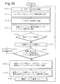
- FIG. 28 It is a flowchart of the reception process by the radio network controller shown in FIG. 28 is a flowchart (part 1) of the rearrangement process performed by the wireless network control device shown in FIG. 27; 28 is a flowchart (part 2) of the rearrangement process by the wireless network control device shown in FIG.
- FIG. 25 is a block diagram of the mobile station shown in FIG. 24. It is the 2nd example of the block diagram of the base station shown in FIG. Fig. 25 is an operation flowchart of the mobile station shown in Fig. 24. It is explanatory drawing of the 2nd example of operation
- FIG. 3 is a configuration diagram of a first example of the disclosed communication system.
- the communication system 1 includes a first packet transmitter / receiver 2, a second packet transmitter / receiver 3, and a third packet transmitter / receiver 4.
- the first and second packet transmitting / receiving apparatuses 2 and 3 may be a base station and a radio network controller as in other embodiments described below. Further, the first and second packet transmitting / receiving apparatuses 2 and 3 may be a mobile station and a base station as in other embodiments described below. That is, the first and second packet transmitting / receiving apparatuses 2 and 3 may be in a relationship of a lower apparatus and an upper apparatus.
- the first and second packet transmitting / receiving apparatuses 2 and 3 may be base stations or radio network controllers. That is, the first and second packet transmission / reception devices 2 and 3 do not have to be related to the lower device and the higher device.
- FIG. 4 is a first example of a hardware configuration diagram of the first packet transmitting / receiving apparatus 2 shown in FIG.
- the first packet transmitting / receiving apparatus 2 includes a processor 10, a program storage unit 12 that stores a control program 11, a memory 13, a packet acquisition unit 14, a communication unit 15, a transmission buffer 16, and a reception buffer 17.
- the processor 10 is realized by a data processor such as a CPU, and controls the operation of the first packet transmitting / receiving apparatus 2 by executing a control program 11 stored in the program storage unit 12.
- the program storage unit 12 may store an application program that generates user data by being executed by the processor 10.
- the memory 13 stores data necessary for execution of the control program 11 and application programs, and also stores temporary data generated when these programs are executed.
- the packet acquisition unit 14 acquires a packet transmitted from the first packet transmission / reception device 2 to the second packet transmission / reception device 3.
- Each packet acquired by the packet acquisition unit 14 has a sequence number indicating the order of the packets.
- the sequence number may be embedded in each packet.
- the packet acquisition unit 14 may acquire a packet by receiving a packet from another communication device.
- the packet acquisition unit 14 may be a software module that acquires a packet obtained by dividing user data generated by an application program executed by the processor 10, for example.
- the communication unit 15 transmits / receives data to / from the second packet transmitting / receiving device 3. For example, the communication unit 15 transmits the packet acquired by the packet acquisition unit 14 to the second packet transmitting / receiving apparatus 3.
- the transmission buffer 16 temporarily holds data transmitted to the second packet transmitting / receiving apparatus 3 until the communication unit 15 accepts the data.
- the reception buffer 17 temporarily holds data received from the second packet transmitting / receiving device 3 by the communication unit 15.
- FIG. 5 is a first example of a block diagram of the first packet transmitting / receiving apparatus 2 shown in FIG.
- the processor 10 executes the control program 11 stored in the program storage unit 12, the functions of the packet transmission unit 20, the transmitted packet instruction information generation unit 21, and the transmitted packet instruction information transmission unit 23 are realized.
- the packet transmission unit 20 performs a process of transmitting the packet acquired by the packet acquisition unit 14 to the second packet transmitting / receiving apparatus 3.
- the packet transmission unit 20 inputs a packet to be transmitted to the second packet transmission / reception device 3 to the transmission buffer 16, and the communication unit 15 transmits the packet stored in the transmission buffer 16 to the second packet transmission / reception device 3.
- the transmitted packet instruction information generation unit 21 inputs the packet acquired by the packet acquisition unit 14.
- the transmitted packet instruction information generation unit 21 considers that the packet received from the packet acquisition unit 14 has been transmitted by the packet transmission unit 20, and has transmitted the packet instruction information indicating the packet transmitted by the packet transmission unit 20. Is generated.
- the transmitted packet instruction information may identify the packet transmitted by the packet transmission unit 20 by the sequence number of the transmitted packet.
- the transmitted packet instruction information used in the description in the present specification includes a set of sequence numbers including a series of sequence numbers in which the sequence numbers of the packets transmitted by the packet transmitter 20 are arranged in the order of transmission of the packets. It is.
- the transmitted packet instruction information generation unit 21 extracts the sequence number embedded in each packet from each packet acquired from the packet acquisition unit 14.
- the transmitted packet instruction information generation unit 21 stores the extracted sequence number in the memory 13.
- the transmitted packet instruction information generation unit 21 adds a sequence number of each packet to the sequence number sequence stored in the memory 13 each time the sequence number is extracted. Generate a sequence of numbers.
- the transmitted packet instruction information generation unit 21 reads a sequence number sequence stored in the memory 13 at a transmission timing described later, and transmits transmitted packet instruction information including the sequence number sequence to a transmitted packet instruction information transmission unit. To 23.
- the transmitted packet instruction information transmitting unit 23 performs a process of transmitting the transmitted packet instruction information received from the transmitted packet instruction information generating unit 21 to the second packet transmitting / receiving apparatus 3.
- the transmitted packet instruction information transmitting unit 23 inputs the transmitted packet instruction information to the transmission buffer 16, and the communication unit 15 transmits the transmitted packet instruction information stored in the transmission buffer 16 to the second packet transmitting / receiving apparatus 3. .
- FIG. 6 is a hardware configuration diagram of the second packet transmitting / receiving apparatus 3 shown in FIG.
- the second packet transmitting / receiving apparatus 3 includes a processor 30, a program storage unit 32 that stores a control program 31, a memory 33, a first communication unit 34, a first reception buffer 35, and a first transmission buffer 36.
- the second packet transmitting / receiving apparatus 3 includes a second communication unit 37, a second transmission buffer 38, a second reception buffer 39, and a rearrangement buffer 40.
- the processor 30 is realized by a data processor such as a CPU, and controls the operation of the second packet transmitting / receiving apparatus 3 by executing a control program 31 stored in the program storage unit 32.
- the memory 33 stores data necessary for executing the program such as the control program 31, and also stores temporary data generated when these programs are executed.
- the first communication unit 34 transmits / receives data to / from the first packet transmitting / receiving device 2. For example, the first communication unit 34 receives a packet transmitted by the first packet transmitting / receiving apparatus 2. For example, the first communication unit 34 receives the transmitted packet instruction information transmitted by the first packet transmitting / receiving apparatus 2.
- the first reception buffer 35 temporarily holds data received from the first packet transmitting / receiving device 2 by the first communication unit 34.
- the first transmission buffer 36 temporarily holds data transmitted from the second packet transmission / reception device 3 to the first packet transmission / reception device 2 until the first communication unit 34 receives the data.
- the second communication unit 37 transmits / receives data to / from the third packet transmitting / receiving device 4.
- the second communication unit 37 transmits the packets received from the first packet transmitting / receiving device 2 and rearranged in the order of sequence numbers by the rearrangement processing by the processor 30 described below to the third packet transmitting / receiving device 4.
- the second reception buffer 39 temporarily holds data received from the third packet transmitting / receiving device 4 by the second communication unit 37.
- the second transmission buffer 38 temporarily holds data transmitted from the second packet transmission / reception device 3 to the third packet transmission / reception device 4 until the second communication unit 37 accepts the data.
- the rearrangement buffer 40 is a buffer used for saving received packets from the first reception buffer 35 as necessary during rearrangement processing of packets received from the first packet transmitting / receiving apparatus 2.
- FIG. 7 is a first example of a block diagram of the second packet transmitting / receiving apparatus 3 shown in FIG.
- the processor 30 executes the control program 31 stored in the program storage unit 32, the functions of the packet reception unit 50, the transmitted packet instruction information reception unit 51, the rearrangement processing unit 52, and the packet transmission unit 53 are realized.
- the packet receiving unit 50 performs reception processing of the received packet received by the first communication unit 34 and stored in the first reception buffer 35.
- the transmitted packet instruction information receiving unit 51 performs reception processing of the transmitted packet instruction information received by the first communication unit 34 and stored in the first reception buffer 35.
- the rearrangement processing unit 52 performs rearrangement processing for rearranging the packets received from the first packet transmitting / receiving apparatus 2 in the order of the sequence numbers of the respective packets. At the time of the rearrangement process, the rearrangement processing unit 52 saves the packet read from the first reception buffer 35 in the rearrangement buffer 40 as necessary.
- the packet transmission unit 53 performs processing for transmitting packets to the third packet transmitting / receiving device 4 in the order rearranged by the rearrangement processing unit 52.
- the packet transmission unit 53 inputs a packet transmitted to the third packet transmission / reception device 4 to the second transmission buffer 38, and the second communication unit 37 transmits the packet stored in the second transmission buffer 38 to the third packet transmission / reception device 4 to send.
- FIG. 8 is a first example of an operation flowchart of the first packet transmitting / receiving apparatus 2 shown in FIG.
- the packet acquisition unit 14 acquires a packet transmitted from the first packet transmission / reception device 2 to the second packet transmission / reception device 3.
- the acquired packet may be a packet that stores user data received from another communication device or a packet that stores user data generated by an application program executed by the processor 10.
- step S2 the transmitted packet instruction information generation unit 21 acquires the sequence number embedded in the packet acquired in step S1.
- step S3 the packet transmitter 20 transmits the packet acquired in step S1 to the second packet transmitting / receiving apparatus 3.
- step S4 the transmitted packet instruction information generation unit 21 stores the sequence number acquired in step S2 in the memory 13.
- the transmitted packet instruction information generation unit 21 newly stores it after the sequence number already stored in the memory 13. Add a sequence number.
- step S5 the transmitted packet instruction information generation unit 21 determines whether or not the sequence number acquired in step S2 is an expected sequence number.
- the “expected sequence number” is the sequence number that has the earliest transmission order among the sequence numbers of untransmitted packets. In this embodiment, it is assumed that the transmission order is determined in ascending order. In this case, the “expected sequence number” is the smallest sequence number among the sequence numbers among the untransmitted packets. If for some reason a packet is not transmitted in the order of the sequence number and a packet that is overtaken by a subsequent packet is generated, the sequence number of the overtaken packet is the smallest sequence number.
- step S5 N
- the processor 10 returns the process to step S1.
- the transmitted packet instruction information generation unit 21 stores in the memory 13 a sequence number sequence of transmitted packets having a sequence number after the expected sequence number.
- step S6 sets the value of the index variable i to (expected Set to sequence number + 1).
- steps S7 and S8 the transmitted packet instruction information generation unit 21 searches for the minimum expected sequence number that is not stored in the memory 13. That is, in step S7, the transmitted packet instruction information generation unit 21 determines whether or not a sequence number equal to the value of the index variable i is stored in the memory 13. As long as the sequence number equal to the value of the index variable i is stored in the memory 13 (step S7: Y), the transmitted packet instruction information generation unit 21 increments the value of the index variable i by 1 in step S8. Steps S7 and S8 are repeated.
- step S9 the transmitted packet instruction information generation unit 21 continues the sequence from the expected sequence number to (i-1). Generate transmitted packet instruction information including a number.
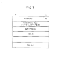
- FIG. 9 is a diagram showing a frame format of the transmitted packet instruction information.
- the transmitted packet instruction information includes a header part (Header CRC), an FT field, a Control Frame Type field, a notification TSN number field, and one or more TSN # 0 to TSN # (n-1) fields.
- the value of the FT field indicates whether this frame is a control frame or a data frame.
- the value of the Control Frame Type field indicates that this frame is transmitted packet instruction information for notifying sequence data.
- the value of the notification TSN number field indicates the total number of sequence numbers notified by the transmitted packet instruction information. Sequence numbers are stored in the TSN # 0 to TSN # (n-1) fields, respectively.
- the transmitted packet instruction information transmitting unit 23 transmits the transmitted packet instruction information to the second packet transmitting / receiving apparatus 3.
- step S10 of FIG. 8 the transmitted packet instruction information generation unit 21 deletes the sequence numbers from the expected sequence number stored in the memory 13 to (i-1).
- step S11 the transmitted packet instruction information generation unit 21 updates the value of the expected sequence number to the value of the index variable i. After that, the processor 10 returns the process to step S1.
- FIG. 10 is an explanatory diagram of the operation of the communication system 1 shown in FIG.
- each packet storing user data is shown as a square surrounded by values “1” to “5”, and each value surrounded by the square represents a sequence number of each packet.
- the transmitted packet instruction information is shown as a square surrounding the character “S”.
- the first packet transmitting / receiving apparatus 2 sequentially acquires packets having sequence numbers 1 to 5 as indicated by reference numeral 60 (step S1 in FIG. 8). At this time, it is assumed that the acquisition of the packet of sequence number 2 by the first packet transmitting / receiving apparatus 2 is delayed for some reason, and the packet of sequence number 2 is acquired after receiving the packet of sequence number 5. In this case, the sequence numbers “1”, “3”, “4”, “5”, and “2” are transmitted to the second packet transmitting / receiving apparatus 3 in the order (step S3).
- the value of the expected sequence number becomes “2” due to failure to acquire the packet of sequence number 2. Therefore, the sequence numbers “3”, “4”, and “5” are stored in the memory 13 until the first packet transmitting / receiving apparatus 2 acquires the packet with the sequence number 2.
- the transmitted packet instruction information generating unit 21 When the first packet transmitting / receiving apparatus 2 acquires the packet having the sequence number 2 (step S5: Y), the transmitted packet instruction information generating unit 21 generates the transmitted packet instruction information S including the sequence numbers 2 to 5 (step S5). S9).
- the transmitted packet instruction information S may have sequence numbers 2 to 5 arranged according to the packet transmission order. For example, in this example, the sequence numbers 2 to 5 stored in the transmitted packet instruction information S are arranged in the order of “3”, “4”, “5”, “2”.
- Reference numeral 61 indicates a state in which the transmitted packet instruction information S is transmitted to the second packet transmitting / receiving apparatus 3 after the packet having the sequence number “2”.
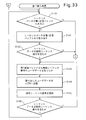
- FIG. 11 is a flowchart of the reception process by the second packet transmitting / receiving apparatus 3 shown in FIG.
- the first communication unit 34 of the second packet transmitting / receiving apparatus 3 receives the packet transmitted from the first packet transmitting / receiving apparatus 2 and / or the transmitted packet instruction information.
- the first communication unit 34 stores the data received in step S20 in the first reception buffer 35 in the order of reception.
- the second packet transmitting / receiving apparatus 3 stores the data received from the first packet transmitting / receiving apparatus 2 in the first receiving buffer 35 by repeating steps S20 and S21.
- the rearrangement processing unit 52 shown in FIG. 7 rearranges the packets received from the first packet transmission / reception device 2 and stored in the first reception buffer 35 in the order of the sequence numbers of the respective packets, and then transmits and receives the third packet. Transfer to device 4. 12 and 13 are flowcharts of the rearrangement process by the second packet transmitting / receiving apparatus 3 shown in FIG.
- step S30 the rearrangement processing unit 52 determines whether there is transmitted packet instruction information stored in the first reception buffer 35. When there is no transmitted packet instruction information stored in the first reception buffer 35 (step S30: N), the rearrangement processing unit 52 proceeds to step S37 (reference number A). If there is transmitted packet instruction information stored in the first reception buffer 35 (step S30: Y), the rearrangement processing unit 52 proceeds to step S31.
- step S31 the rearrangement processing unit 52 takes out the transmitted packet instruction information from the first reception buffer 35.
- step S32 the rearrangement processing unit 52 determines whether or not the expected sequence number is included in the sequence number indicated by the extracted transmitted packet instruction information.
- the “expected sequence number” is the smallest sequence number among the untransmitted packets and the rearrangement processing is still performed for the subsequent packets. This is the sequence number of the packet that has not been subjected to the reordering process by the unit 52.
- step S32: N When the expected sequence number is not included in the sequence number indicated by the transmitted packet instruction information (step S32: N), the rearrangement processing unit 52 proceeds to step S37 (reference number A). When the expected sequence number is included in the sequence number indicated by the transmitted packet instruction information (step S32: Y), the rearrangement processing unit 52 proceeds to step S33.
- step S33 the packet receiving unit 50 takes out the packet having the expected sequence number from the first reception buffer 35.
- step S34 the packet transmission unit 53 transmits the packet extracted in step S33 to the third packet transmitting / receiving apparatus 4.
- step S35 the rearrangement processing unit 52 updates the expected sequence number by incrementing the expected sequence number by one.
- step S36 the rearrangement processing unit 52 determines whether or not the updated expected sequence number is included in the sequence number indicated by the transmitted packet instruction information.
- the rearrangement processing unit 52 returns the process to step S33.
- the processor 30 repeatedly executes steps S33 to S36.
- the processor 30 can take out the packets of the sequence numbers that are consecutive from the first reception buffer 35 in accordance with the order of the sequence numbers and transmit them to the third packet transmitting / receiving apparatus 4. That is, by taking out the packets from the first reception buffer 35 in the order of the sequence numbers, the rearrangement processing unit 52 can perform the rearrangement process without using the rearrangement buffer.
- step S36: N the processor 30 returns the process to step S30.
- step S37 the rearrangement processing unit 52 determines whether or not the received packet is stored in the first reception buffer 35. If there is a received packet (step S37: Y), the rearrangement processing unit 52 proceeds to step S38. When there is no received packet (step S37: N), the rearrangement processing unit 52 proceeds to step S44.
- step S ⁇ b> 38 the rearrangement processing unit 52 saves the packet in the first reception buffer 35 to the rearrangement buffer 40 by copying the packet extracted from the first reception buffer 35 by the packet reception unit 50 to the rearrangement buffer 40. To do.
- the rearrangement processing unit 52 stores newly stored packets in addition to the already stored packets.
- step S39 the rearrangement processing unit 52 determines whether or not the sequence number of the packet saved in the rearrangement buffer 40 in step S38 is the same as the expected sequence number.
- the rearrangement processing unit 52 moves the process to step S40.
- step S40 the rearrangement processing unit 52 transmits one or more consecutive packets including the packet of the expected sequence number among the packets stored in the rearrangement buffer 40 to the third packet transmitting / receiving apparatus 4.
- step S41 the rearrangement processing unit 52 updates the value of the expected sequence number to (the maximum value of the sequence number of the packet transmitted in S40 + 1).
- step S42 the rearrangement processing unit 52 determines whether the rearrangement timer is running.
- the rearrangement timer may be a software timer realized by the processing of the processor 30, for example. Time measurement by the reordering timer starts when a packet having a sequence number that is not the expected sequence number is saved in the empty reordering buffer 40.
- the rearrangement timer is a timer used for transmitting a packet remaining in the rearrangement buffer 40 to the third packet transmitting / receiving apparatus 4 when a predetermined time or more has elapsed after the packet is saved in the rearrangement buffer 40. .
- step S42 If it is determined in step S42 that the reordering timer is not activated (step S42: N), the reordering unit 52 proceeds to step S43.
- step S43 the rearrangement processing unit 52 activates the rearrangement timer and starts time measurement by the rearrangement timer. Thereafter, the rearrangement processing unit 52 proceeds to step S44. If it is determined in step S42 that the rearrangement timer has already been started (step S42: Y), the rearrangement processing unit 52 proceeds to step S44.
- step S44 the rearrangement processing unit 52 determines whether the rearrangement timer is running. When the reordering timer is not activated (step S44: N), the processor 30 returns the process to step S30 (reference numeral B). When the rearrangement timer is activated (step S44: Y), the rearrangement processing unit 52 proceeds to step S45.
- step S45 the rearrangement processing unit 52 determines whether or not the time measured by the rearrangement timer has exceeded a predetermined time, that is, whether or not the time measured by the rearrangement timer has timed out.
- a predetermined time that is, whether or not the time measured by the rearrangement timer has timed out.
- step S46 the rearrangement processing unit 52 transmits all the packets stored in the rearrangement buffer 40 to the third packet transmitting / receiving apparatus 4.
- step S47 the rearrangement processing unit 52 updates the value of the expected sequence number to (the maximum value of the sequence number of the packet transmitted in S46 + 1).
- step S48 the rearrangement processing unit 52 stops the rearrangement timer. Thereafter, the processor 30 returns the process to step S30 (reference numeral B).
- step S45 when the time measured by the rearrangement timer has not timed out (step S45: N), the rearrangement processing unit 52 proceeds to step S49.
- step S49 the rearrangement processing unit 52 increases the measurement value of the rearrangement timer by a predetermined time step and updates the measurement value. Thereafter, the processor 30 returns the process to step S30 (reference numeral B).
- the first packet transmitting / receiving apparatus 2 transmits the packets including the sequence numbers 2 to 5 after transmitting the packets in the order of the sequence numbers “1”, “3”, “4”, “5”, “2”.
- the completed packet instruction information S is transmitted.
- the first reception buffer 35 of the second packet transmitting / receiving apparatus 3 stores packets arranged in the order of reception, that is, in the order of sequence numbers “1”, “3”, “4”, “5”, “2”. Thereafter, the transmitted packet instruction information S is stored.
- the sequence numbers 2 to 5 stored in the transmitted packet instruction information S are arranged in the order of “3”, “4”, “5”, “2”.
- the processor 30 may not be able to start processing this packet immediately.
- this packet is processed before the processing order of this packet arrives. Is considered to be completed.
- the rearrangement processing unit 52 of the second packet transmitting / receiving apparatus 3 receives the subsequent packet of the sequence numbers “2” to “5” and the transmitted packet instruction information S, and then receives the sequence number “1”. Start processing.
- FIG. 10 shows a state where the rearrangement buffer 40 is empty. Such a state occurs when the process does not proceed to step S37 and subsequent steps shown in FIG. 13 and the packet is not saved in the rearrangement buffer 40.
- the sequence number of the packet taken out from the first reception buffer 35 matches the expected sequence number, and the rearrangement processing unit 52 repeats steps S30 to S36 shown in FIG. Therefore, the expected sequence number is “2” when the rearrangement processing unit 52 extracts the transmitted packet instruction information S from the first reception buffer 35 after the packet with the sequence number “1”.
- the rearrangement processing unit 52 Based on the transmitted packet instruction information S (step S31 in FIG. 12), the rearrangement processing unit 52 receives the packet with the expected sequence number “2” and the subsequent sequence numbers “3” to “5” from the first reception. It can be known that it is stored in the buffer 35. For this reason, in steps S33 to S36, the rearrangement processing unit 52 can take out the consecutive packets having the sequence numbers “2” to “5” from the first reception buffer 35 in the order of the sequence numbers.
- the rearrangement processing unit 52 causes the packet transmission unit 53 to transmit packets according to the order extracted from the first reception buffer 35.
- the second transmission buffer 38 stores packets waiting for the transmission order.
- the order of the packets stored in the second transmission buffer 38 follows the order of the sequence numbers.
- the squares denoted by reference numeral 63 indicate the storage positions in the second transmission buffer 38. In the figure, the transmission order is earlier in the data stored in the upper cells.
- the number written in each square indicates the sequence number of the stored packet.
- the character “x” indicates that the preceding packet is stored, the character “e” indicates an empty storage position, and the character “a” follows the packets of the sequence numbers “2” to “5”. Indicates an available storage location.
- the squares indicated by reference numeral 64 mean time charts of packets transmitted from the second packet transmitting / receiving device 3 to the third packet transmitting / receiving device 4.
- the data stored in the square on the right side has a higher transmission order.
- the numbers described in squares indicate the sequence number of the packet.
- the letter “x” indicates the preceding packet
- the letter “e” indicates an empty time slot
- the letter “a” indicates an available time slot after the packets with sequence numbers “2” to “5”. .
- the notation used in FIG. 10 is also used in FIG. 29, FIG. 31, and FIG.
- the rearrangement processing unit 52 performs packet rearrangement processing without saving the packets in the rearrangement buffer 40.
- the rearrangement processing unit 52 can read the packet from the first reception buffer 35 according to the sequence number order. That is, even if a packet with an older sequence number is received after a packet with a lower sequence number, the packet with the older sequence number can be read out from the first reception buffer 35 first and transmitted.
- the packets are taken out from the first reception buffer 35 in the received order. For this reason, when the order of the sequence numbers does not match the order of reception, the transmission processing of these packets is performed until all subsequent packets received earlier than the packets with the older sequence numbers are saved in the rearrangement buffer 40. Must be delayed.
- the rearrangement process in steps S33 to S36 can prevent a delay in the packet transmission process that occurs in the rearrangement process using the rearrangement buffer 40 as described above.
- Reference numeral 66 in FIG. 10 indicates that the delay in transmission processing of the packets with the sequence numbers “2” to “5” can be reduced and the available time slots can be increased.
- the packet saved in the rearrangement buffer 40 when the packet having the expected sequence number is taken out from the first reception buffer 35 is immediately transmitted to the third packet.
- the data is transmitted to the transmission / reception device 4. For this reason, a transmission burst is generated, and a load on the third packet transmitting / receiving apparatus 4 is generated.
- the transmission burst causes data loss. For this reason, the rearrangement process using the rearrangement buffer 40 causes a reduction in communication throughput in the communication system 1.
- steps S33 to S36 the rearrangement processing unit 52 alternately performs the packet reading process from the first reception buffer 35 and the packet transmission process.
- Such a process of alternately performing reading and transmission is the same as the process in the case where the rearrangement process does not occur, and therefore the transmission interval of each packet does not greatly differ from the case in which the rearrangement process does not occur. Therefore, the rearrangement process performed in steps S33 to S36 can prevent transmission bursts.
- Reference numeral 65 in FIG. 10 indicates that the transmission interval of packets with sequence numbers “1” to “5” is maintained and transmission bursts are prevented.
- the rearrangement processing unit 52 determines the storage order of each packet in the first reception buffer 35 based on the transmitted packet instruction information. be able to. In this case, the rearrangement processing unit 52 can take out a packet having a desired sequence number from the first reception buffer 35 without referring to the sequence number embedded in each packet.
- the rearrangement process using the rearrangement buffer for example, after a packet that is user data is stored in the reception buffer, the stored packet is copied to the rearrangement buffer, so that the processing of the processor of the reception apparatus increases. For this reason, there is a risk of processing delay of user data and failure of the data transmission function due to overload of the processor of the receiving apparatus.
- the second packet transmitting / receiving apparatus 3 when the processing of the second packet transmitting / receiving apparatus 3 is delayed and a large number of packets are accumulated in the first reception buffer 35, the transmitted packet instruction is also added to these packets. Information is also stored in the first reception buffer 35. Therefore, the second packet transmitting / receiving apparatus 3 can perform the rearrangement process when taking out the packet from the first reception buffer 35 with reference to the transmitted packet instruction information. Since overloading of the processor 30 due to the use of the rearrangement buffer can be prevented, the above-described problems such as user data processing delay and data transmission function failure can be solved.
- bursts of data transmitted from the second packet transmitting / receiving apparatus 3 can be prevented.
- the present embodiment can solve problems such as induction of functional failure of the communication system 1 due to communication bursts and missing user data due to shaping.
- transmission power may be suppressed in radio communication between the mobile station and the base station in order to effectively use radio resources.
- the HARQ retransmission rate increases, the sequence number order does not match the reception order, and the load of user data rearrangement processing in the radio network controller increases.
- the rearrangement process of the present embodiment can contribute to reducing the load of the user data rearrangement process in the radio network controller.
- FIG. 14 is a second example of an operation flowchart of the first packet transmitting / receiving apparatus 2 shown in FIG.
- the first packet transmitting / receiving apparatus 2 transmits the transmitted packet instruction information to the second packet transmitting / receiving apparatus 3 at a constant cycle.
- the first packet transmitting / receiving apparatus 2 sequentially stores the acquired packet sequence numbers in the memory 13 during a predetermined transmission period. At each periodic transmission time, the first packet transmitting / receiving apparatus 2 transmits transmitted packet instruction information including the sequence number stored in the memory 13 to the second packet transmitting / receiving apparatus 3. Specific processing will be described with reference to FIG.
- step S50 the packet acquisition unit 14 acquires a packet in the same manner as in step S1 shown in FIG.
- step S51 the transmitted packet instruction information generation unit 21 acquires the sequence number embedded in the packet acquired in step S50.
- step S52 the packet transmission unit 20 transmits the packet acquired in step S50 to the second packet transmitting / receiving apparatus 3.
- step S53 the transmitted packet instruction information generation unit 21 stores the sequence number acquired in step S51 in the memory 13, as in step S4 shown in FIG.
- step S54 the transmitted packet instruction information generation unit 21 determines whether or not the current time is a periodic transmission time for transmitting the transmitted packet instruction information. If the current time is not a periodic transmission time (step S54: N), the processor 10 returns the process to step S50. By repeating the processing of steps S50 to S54 for a predetermined period, the transmitted packet instruction information generating unit 21 stores a sequence number sequence of transmitted packets in the memory 13.
- step S54 When the current time is a periodic transmission time (step S54: Y), the transmitted packet instruction information generation unit 21 in step S55 transmits a transmitted packet instruction including all sequence numbers stored in the memory 13. Generate information.
- the transmitted packet instruction information transmitting unit 23 transmits the transmitted packet instruction information to the second packet transmitting / receiving apparatus 3.
- step S56 the transmitted packet instruction information generation unit 21 deletes the sequence number stored in the memory 13. After that, the processor 10 returns the process to step S50.
- the transmitted packet instruction information generation unit 21 can generate transmitted packet instruction information by a relatively simple process of periodically counting sequence numbers. For this reason, this embodiment can be realized without imposing a heavy load on the processing processor 10 of the first packet transmitting / receiving apparatus 2.
- FIG. 15 is a second example of the block diagram of the first packet transmitting / receiving apparatus 2 shown in FIG. 4, and FIG. 16 is a second example of the block diagram of the second packet transmitting / receiving apparatus 3 shown in FIG.
- the first packet transmitting / receiving apparatus 2 transmits transmitted packet instruction information to the second packet transmitting / receiving apparatus 3 in response to a request from the second packet transmitting / receiving apparatus 3.
- the same reference numerals are assigned to the same components as those shown in FIG. 5. Also, the processor 10 shown in FIG. 4 executes the control program 11 stored in the program storage unit 12, thereby realizing the function of the transmitted packet instruction information request signal receiving unit 24.
- the same constituent elements as those shown in FIG. 7 are denoted by the same reference numerals. Further, the processor 30 shown in FIG. 6 executes the control program 31 stored in the program storage unit 32, thereby realizing the function of the transmitted packet instruction information request signal transmission unit 54.
- the transmitted packet instruction information request signal transmitting unit 54 generates a transmitted packet instruction information request signal for requesting the first packet transmitting / receiving apparatus 2 to transmit the transmitted packet instruction information, and transmits the generated packet instruction information request signal to the first packet transmitting / receiving apparatus 2. Perform the process.
- the transmitted packet instruction information request signal transmitter 54 may periodically transmit a transmitted packet instruction information request signal to the first packet transmitting / receiving apparatus 2.
- the transmitted packet instruction information request signal transmission unit 54 may transmit the transmitted packet instruction information request signal to the first packet transmitting / receiving apparatus 2 in accordance with the instruction of the rearrangement processing unit 52.
- the rearrangement processing unit 52 transmits the transmitted packet instruction information request signal to the transmitted packet instruction information request signal when the processor 30 ends the processing of the packet instructed by the already received transmitted packet instruction information.
- the transmission unit 54 may be instructed.
- the transmitted packet instruction information request signal receiving unit 24 shown in FIG. 15 receives the transmitted packet instruction information request signal transmitted from the second packet transmitting / receiving apparatus 3.
- the packet instruction information request signal receiving unit 24 receives the transmitted packet instruction information request signal
- the transmitted packet instruction information generating unit 21 and the transmitted packet instruction information transmitting unit 23 generate and transmit the transmitted packet instruction information. Do.
- FIG. 17 is a third example of an operation flowchart of the first packet transmitting / receiving apparatus 2 shown in FIG.
- the packet acquisition unit 14 acquires a packet similarly to step S1 shown in FIG.
- the transmitted packet instruction information generation unit 21 acquires the sequence number embedded in the packet acquired in step S60.
- the packet transmission unit 20 transmits the packet acquired in step S60 to the second packet transmitting / receiving apparatus 3.
- the transmitted packet instruction information generation unit 21 stores the sequence number acquired in step S61 in the memory 13, as in step S4 shown in FIG.
- step S64 the transmitted packet instruction information generating unit 21 determines whether the transmitted packet instruction information request signal receiving unit 24 has received the transmitted packet instruction information request signal. If the transmitted packet instruction information request signal has not been received (step S64: N), the processor 10 returns the process to step S60. By repeating the processing of steps S60 to S64 until the transmitted packet instruction information request signal is received, the transmitted packet instruction information generation unit 21 stores a sequence number sequence of transmitted packets in the memory 13. .
- step S64 When the transmitted packet instruction information request signal is received (step S64: Y), the transmitted packet instruction information generation unit 21 in step S65 transmits the transmitted packet including all sequence numbers stored in the memory 13. Generate instruction information.
- the transmitted packet instruction information transmitting unit 23 transmits the transmitted packet instruction information to the second packet transmitting / receiving apparatus 3.
- step S66 the transmitted packet instruction information generation unit 21 deletes the sequence number stored in the memory 13. After that, the processor 10 returns the process to step S60.
- the transmitted packet instruction information can be transmitted according to the demand of the second packet transmitting / receiving apparatus 3 that receives the packet, so that the transmitted packet instruction information is efficiently generated and transmitted. Is possible.
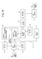
- FIG. 18 is a third example of a functional block diagram of the first packet transmitting / receiving apparatus 2 shown in FIG.
- the first packet transmission / reception device 2 transmits transmitted packet instruction information to the second packet transmission / reception device 3 when a predetermined condition is satisfied after detection of the missing packet.
- the “missing packet” refers to a packet transmitted after the subsequent packet when the packet is not transmitted from the first packet transmitting / receiving apparatus 2 to the second packet transmitting / receiving apparatus 3 in the order of the sequence numbers.
- the processor 10 illustrated in FIG. 4 executes the control program 11 stored in the program storage unit 12, thereby realizing the functions of the missing packet detection unit 25 and the transmission availability determination unit 26.
- the missing packet detector 25 detects the occurrence of a missing packet. For example, the missing packet detector 25 may detect the occurrence of a missing packet by determining whether or not the sequence numbers stored in the memory 13 are discontinuous.
- the transmission availability determination unit 26 determines whether or not a predetermined condition is satisfied after the missing packet detection unit 25 detects the missing packet. When the transmission possibility determination unit 26 determines that a predetermined condition is satisfied, the transmitted packet instruction information generation unit 21 and the transmitted packet instruction information transmission unit 23 generate and transmit transmitted packet instruction information.
- the predetermined condition may be that a predetermined time has elapsed since detection of a missing packet, or that a predetermined number of packets have been transmitted since detection of a missing packet.
- FIG. 19 is a fourth example of an operation flowchart of the first packet transmitting / receiving apparatus 2 shown in FIG.
- the packet acquisition unit 14 acquires a packet similarly to step S1 shown in FIG.
- the transmitted packet instruction information generation unit 21 acquires the sequence number embedded in the packet acquired in step S70.
- the packet transmission unit 20 transmits the packet acquired in step S70 to the second packet transmitting / receiving apparatus 3.
- the transmitted packet instruction information generation unit 21 stores the sequence number acquired in step S81 in the memory 13 as in step S4 shown in FIG.
- the transmission permission / inhibition determination unit 26 refers to the value of the packet loss flag and determines whether or not it is stored that a lost packet is detected.
- the packet loss flag is a variable that can be referred to and changed by the processor 10 and can take a value “T” indicating that a missing packet has occurred and a value “F” indicating that a missing packet has not occurred.
- step S74: N If the value of the packet loss flag is not “T” (step S74: N), the processor 10 moves the process to step S75.
- step S75 the missing packet detector 25 detects whether or not a missing packet has occurred. If a missing packet has occurred (step S75: Y), in step S76, the missing packet detector 25 substitutes the value “T” for the packet loss flag. After that, the processor 10 moves the process to step S70.
- step S75 If there is no missing packet in the determination in step S75 (step S75: N), the processor 10 moves the process to step S70.
- step S74: Y When the value of the packet loss flag is “T” (step S74: Y), the processor 10 moves the process to step S77.
- step S77 the transmission permission determination unit 26 determines whether or not the above-described predetermined condition is satisfied.
- the transmitted packet instruction information generation unit 21 transmits all sequence numbers stored in the memory 13 in step S78. End packet instruction information is generated.
- the transmitted packet instruction information transmitting unit 23 transmits the transmitted packet instruction information to the second packet transmitting / receiving apparatus 3.
- step S79 the transmitted packet instruction information generation unit 21 deletes the sequence number stored in the memory 13.
- step S80 the transmission permission / inhibition determining unit 26 substitutes the value “F” for the packet loss flag. After that, the processor 10 returns the process to step S70.
- the transmission permission determination unit 26 determines that the predetermined condition is not satisfied in the determination in step S77 (step S77: N), the processor 10 returns the process to step S70.
- the transmitted packet instruction information can be transmitted without determining whether the lost packet has been transmitted. For this reason, this embodiment can be realized without imposing a heavy load on the processing processor 10 of the first packet transmitting / receiving apparatus 2.
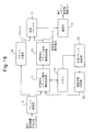
- FIG. 20 is a second example of a hardware configuration diagram of the first packet transmitting / receiving apparatus 2 shown in FIG.
- the first packet transmission / reception device 2 performs a retransmission control process for packets to be transmitted to the second packet transmission / reception device 3. Therefore, the first packet transmitting / receiving apparatus 2 includes a retransmission control unit 18.
- the retransmission control executed between the first packet transmission / reception device 2 and the second packet transmission / reception device 3 may be HARQ control, for example.
- the first packet transmitting / receiving device 2 determines whether each packet has been transmitted to the second packet transmitting / receiving device 3 based on the acknowledge signal received from the second packet transmitting / receiving device 3.
- FIG. 21 is a block diagram of the first packet transmitting / receiving apparatus 2 shown in FIG.
- the processor 10 shown in FIG. 4 executes the control program 11 stored in the program storage unit 12, the functions of the ACK acquisition unit 27 and the sequence number acquisition unit 28 are realized.
- the ACK acquisition unit 27 acquires an acknowledge signal received from the second packet transmitting / receiving apparatus 3 for each packet by the retransmission control performed by the retransmission control unit 18.
- the sequence number acquisition unit 28 acquires the sequence number of the packet from the acknowledge signal acquired by the ACK acquisition unit 27 for each packet.
- the transmitted packet instruction information generation unit 21 inputs the sequence number of the packet transmitted by the packet transmission unit 20 from the sequence number acquisition unit 28, and the packet transmitted by the packet transmission unit 20 according to the input sequence number Is identified.
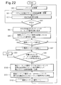
- FIG. 22 is an example of an operation flowchart of the first packet transmitting / receiving apparatus 2 shown in FIG.
- the packet acquisition unit 14 acquires a packet similarly to step S1 shown in FIG.
- the packet transmission unit 20 transmits the packet acquired in step S90 to the second packet transmitting / receiving apparatus 3.
- the communication unit 15 receives an acknowledge signal (ACK) or a negative acknowledgment signal (NACK) from the second packet transmitting / receiving apparatus 3 for the packet transmitted in step S91.
- ACK acknowledge signal
- NACK negative acknowledgment signal
- step S93 the processor 10 determines whether or not the communication unit 15 has received an acknowledge signal.
- the processor 10 receives a negative response signal (S93: N)
- the processor 10 returns the process to step S91 and retransmits the packet.
- the processor 10 moves the process to step S94.
- step S94 the ACK acquisition unit 27 acquires an acknowledge signal from the reception buffer 17. Then, the sequence number acquisition unit 29 extracts the sequence number of the packet for which the acknowledge signal is returned from the acquired acknowledge signal. The transmitted packet instruction information generation unit 21 inputs the extracted sequence number from the sequence number acquisition unit 28.
- step S95 the transmitted packet instruction information generation unit 21 stores the sequence number acquired in step S94 in the memory 13, as in step S4 shown in FIG.
- step S96 the transmitted packet instruction information generation unit 21 determines whether or not the sequence number acquired in step S94 is an expected sequence number. If the sequence number acquired in step S94 is not the expected sequence number (step S96: N), the processor 10 returns the process to step S90.
- step S97 the transmitted packet instruction information generation unit 21 sets the value of the index variable i to (expected sequence number + 1). Set.
- steps S98 and S99 the transmitted packet instruction information generation unit 21 searches for the minimum expected sequence number that is not stored in the memory 13. That is, in step S98, the transmitted packet instruction information generation unit 21 determines whether or not a sequence number equal to the value of the index variable i is stored in the memory 13. As long as a sequence number equal to the value of the index variable i is stored in the memory 13 (step S98: Y), the transmitted packet instruction information generation unit 21 increments the value of the index variable i by 1 in step S99. Steps S99 and S98 are repeated.
- step S100 the transmitted packet instruction information generation unit 21 continues the sequence from the expected sequence number to (i-1). Generate transmitted packet instruction information including a number.
- the transmitted packet instruction information transmitting unit 23 transmits the transmitted packet instruction information to the second packet transmitting / receiving apparatus 3.
- step S101 the transmitted packet instruction information generation unit 21 deletes consecutive sequence numbers from the expected sequence number stored in the memory 13 to (i-1).
- step S102 the transmitted packet instruction information generation unit 21 updates the value of the expected sequence number to the value of the index variable i. After that, the processor 10 returns the process to step S90.
- the first packet transmitting / receiving apparatus 2 can determine whether or not the packet having the expected sequence number has been transmitted more accurately.
- FIG. 23 is a configuration diagram of a second example of the disclosed communication system.
- the communication system 100 includes a mobile station (UE) 101, a base station (NodeB) 102, a radio network controller (RNC) 103, and an xGSN 104.
- the communication system 100 is a W-CDMA mobile communication system, and the communication system 100 provides an HSUPA service in the uplink from the mobile station 101 to the host device.
- the first packet transmitting / receiving apparatus 2 shown in FIG. 3 is applied to the base station 102
- the second packet transmitting / receiving apparatus 3 is applied to the radio network controller 103
- the third packet transmitting / receiving apparatus 4 is applied to the xGSN 104. explain.
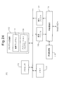
- FIG. 24 is a hardware configuration diagram of the mobile station 101 shown in FIG.
- the base station 101 includes a processor 110, a program storage unit 112 that stores a control program 111, a memory 113, a wireless communication unit 115, a transmission buffer 116, a reception buffer 117, and a retransmission control unit 118.
- the processor 110 is realized by a data processor such as a CPU, and controls the operation of the mobile station 101 by executing a control program 111 stored in the program storage unit 112.
- the program storage unit 112 may store an application program 119 that is executed by the processor 110 to generate user data.
- the memory 113 stores data necessary for the execution of the control program 111 and the application program 119, and stores temporary data generated when these programs are executed.
- the mobile station 101 divides user data generated by the application program 119 into frames having a predetermined format, and then transmits the frames to the base station 102.
- the frame may be a MAC-es PDU.
- Each frame for transmitting user data has a sequence number indicating the order of the frames. The sequence number may be embedded in each frame.
- a frame obtained by dividing user data may be simply referred to as “user data”.
- the wireless communication unit 115 has a wireless communication function with the base station 102, which is a higher-level device of the mobile station 101. For example, the wireless communication unit 115 transmits user data to the base station 102. Further, the wireless communication unit 115 receives from the base station 102 an acknowledge signal or a negative response signal for the transmitted user data.
- the transmission buffer 116 temporarily holds data transmitted to the base station 102 until the wireless communication unit 115 accepts the data.
- the reception buffer 117 temporarily holds data received from the base station 102 by the wireless communication unit 115.
- the retransmission control unit 118 performs a wireless communication retransmission control process with the base station 102 by the wireless communication unit 115.
- the retransmission control by the retransmission control unit 118 may be HARQ control, for example.
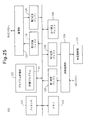
- FIG. 25 is a hardware configuration diagram of the base station 102 shown in FIG.
- the base station 102 includes a processor 120, a program storage unit 122 that stores a control program 121, a memory 123, a wireless communication unit 124, a first reception buffer 125, and a first transmission buffer 126.
- the base station 102 also includes a communication unit 127, a second transmission buffer 128, a second reception buffer 129, a rearrangement buffer 130, and a retransmission control unit 131.
- the processor 120 is realized by a data processor such as a CPU, and controls the operation of the base station 102 by executing a control program 121 stored in the program storage unit 122.
- the memory 123 stores data necessary for executing a program such as the control program 121, and also stores temporary data generated when these programs are executed.
- the wireless communication unit 124 has a wireless communication function with the mobile station 101. For example, the wireless communication unit 124 receives user data transmitted by the mobile station 101. In addition, the wireless communication unit 124 transmits an acknowledgment signal or a negative acknowledgment signal regarding user data received from the mobile station 101 to the mobile station 101.
- the first reception buffer 125 temporarily holds data received from the mobile station 101 by the wireless communication unit 124.
- the first transmission buffer 126 temporarily holds data transmitted from the base station 102 to the mobile station 101 until the wireless communication unit 124 accepts the data.
- the communication unit 127 performs data transmission / reception with the wireless network control device 103 which is a host device of the base station 101. For example, the communication unit 127 transmits user data received from the mobile station 101 to the radio network controller 103.
- the second reception buffer 129 temporarily holds data received from the radio network controller 103 by the communication unit 127.
- the second transmission buffer 128 temporarily holds data transmitted from the base station 102 to the radio network controller 103 until the communication unit 127 accepts the data.
- the retransmission control unit 131 performs a wireless communication retransmission control process with the mobile station 101 by the wireless communication unit 124.
- the rearrangement buffer 130 will be described later.
- FIG. 26 is a first example of a block diagram of the base station 102 shown in FIG.
- the processor 120 executes the control program 121 stored in the program storage unit 122, the functions of the user data transmission unit 132, the sequence data generation unit 133, and the sequence data transmission unit 135 are realized.
- the user data transmission unit 132 performs processing for transmitting the user data received from the mobile station 101 by the wireless communication unit 124 to the wireless network control device 103.
- the user data transmission unit 132 inputs a packet to be transmitted to the radio network controller 103 to the second transmission buffer 128, and the communication unit 127 transmits the packet stored in the second transmission buffer 128 to the radio network controller 103. To do.
- the sequence data generation unit 133 inputs user data received from the mobile station 101, acquires sequence numbers from these user data, and generates sequence data including these sequence numbers.
- the sequence data indicates user data transmitted by the user data transmitting unit 132, and corresponds to an example of transmitted packet instruction information in the other embodiments described above.
- the sequence data generation unit 133 includes a column n1 in which these numbers are arranged in the order of reception.
- N2, n3, and n4 may be sequence data.
- the sequence data generation unit 133 extracts the embedded sequence number from each user data received from the mobile station 101.
- the sequence data generation unit 133 stores the extracted sequence number in the memory 123.
- Each time the sequence data generation unit 133 extracts the sequence number of each user data the sequence data is added to the sequence number column stored in the memory 123 so that the sequence number is arranged in the order of reception of the user data.
- Generate a column of The sequence data generation unit 133 reads out a sequence number sequence stored in the memory 123 at a transmission timing described later, and outputs sequence data including the sequence number sequence to the sequence data transmission unit 135.
- the user data transmission unit 132 transmits user data to the radio network controller 103 in the order received from the mobile station 101
- the sequence number included in the sequence data is ordered from the base station 102 to the radio network controller 103. It is the same as the transmission order of the user data to.
- the sequence data transmission unit 135 performs a process of transmitting the sequence data generated by the sequence data generation unit 133 to the radio network controller 103.
- the sequence data transmission unit 135 inputs the sequence data to the second transmission buffer 128, and the communication unit 127 transmits the sequence data stored in the second transmission buffer 128 to the radio network controller 103.
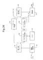
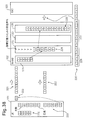
- FIG. 27 is a hardware configuration diagram of the radio network controller 103 shown in FIG.
- the wireless network control apparatus 103 includes a processor 140, a program storage unit 142 that stores a control program 141, a memory 143, a first communication unit 144, a first reception buffer 145, and a first transmission buffer 146.
- the radio network controller 103 includes a second communication unit 147, a second transmission buffer 148, a second reception buffer 149, and a rearrangement buffer 150.
- the processor 140 is realized by a data processor such as a CPU, and controls the operation of the radio network controller 103 by executing a control program 141 stored in the program storage unit 142.
- the memory 143 stores data necessary for executing a program such as the control program 141, and stores temporary data generated when these programs are executed.
- the first communication unit 144 transmits / receives data to / from the base station 102.
- the first communication unit 144 receives user data transmitted from the base station 102.
- the first communication unit 144 receives the sequence data transmitted from the base station 102.
- the first reception buffer 145 temporarily holds data received from the base station 102 by the first communication unit 144.
- the first transmission buffer 146 temporarily holds data transmitted from the radio network controller 103 to the base station 102 until the first communication unit 144 accepts the data.
- the second communication unit 147 transmits / receives data to / from the xGSN 104 that is a higher-level device of the wireless network control device 103. For example, the second communication unit 147 transmits user data received from the mobile station 101 to the xGSN 104.
- the second reception buffer 149 temporarily holds data received from the xGSN 104 by the second communication unit 147.
- the second transmission buffer 148 temporarily holds data transmitted from the radio network controller 103 to the xGSN 104 until the second communication unit 147 receives the data.
- the reordering buffer 150 is used to save the received user data from the first reception buffer 145 as necessary during the reordering process of the user data received from the base station 102. Buffer.
- FIG. 28 is a block diagram of the radio network controller 103 shown in FIG.
- the processor 140 executes the control program 141 stored in the program storage unit 142, the functions of the user data reception unit 151, the sequence data reception unit 152, the rearrangement processing unit 153, and the user data transmission unit 154 are realized. .
- the user data reception unit 151 performs reception processing of user data received by the first communication unit 144 and stored in the first reception buffer 145.
- the sequence data reception unit 152 performs reception processing of the sequence data received by the first communication unit 144 and stored in the first reception buffer 145.
- the rearrangement processing unit 153 performs rearrangement processing for rearranging the user data received from the base station 102 in the order of the sequence numbers of the respective user data. In the rearrangement process, the rearrangement processing unit 153 saves the packet read from the first reception buffer 145 in the rearrangement buffer 150 as necessary.
- the user data transmission unit 154 performs processing for transmitting packets to the xGSN 104 in the order rearranged by the rearrangement processing unit 153.
- the user data transmission unit 154 inputs a packet transmitted to the xGSN 104 to the second transmission buffer 148, and the second communication unit 147 transmits the packet stored in the second transmission buffer 148 to the xGSN 104.
- FIG. 29 is an explanatory diagram of the rearrangement process using the rearrangement buffer 150.
- Reference numeral 200 indicates user data generated by an application program 119 operating on the mobile station 101. Each square represents each user data divided into data frames, and numerals “1” to “5” surrounded by the squares represent sequence numbers of the respective user data.
- Reference numerals 201 and 202 indicate user data transmitted from the mobile station 101 to the base station 102 and from the base station 102 to the radio network controller 103, respectively.
- the user data located above is earlier in transmission time.
- reference numeral 211 in the transmission from the mobile station 101 to the base station 102, the initial data transmission of the user data with the sequence number “2” has failed, and the sequence number “2” is the sequence number “5” due to retransmission control. Is retransmitted after the user data.
- the base station 102 transmits user data to the radio network controller 103 in the order of sequence numbers “1”, “3”, “4”, “5”, “2” as indicated by reference numeral 202. . Therefore, the first reception buffer 145 of the radio network controller 103 stores user data in the order of reception, that is, in the order of sequence numbers “1”, “3”, “4”, “5”, “2”. .
- the rearrangement processing unit 153 of the wireless network control apparatus 103 starts the processing of the sequence number “1” after the storage of the subsequent user data of the sequence numbers “2” to “5” is completed.
- the positional relationship in the vertical direction of the user data described in the first reception buffer 145, the rearrangement processing unit 153, and the rearrangement buffer 150 schematically indicates processing timings in the respective components 145, 153, and 150.
- the rearrangement processing unit 153 extracts user data from the first reception buffer 145 in the received order. For this reason, the rearrangement processing unit 153 saves subsequent user data received earlier than user data having an older sequence number in the rearrangement buffer 150 when the order of the sequence numbers does not match the reception order. .
- the rearrangement processing unit 153 saves the user data having the sequence numbers “3” to “5” to the rearrangement buffer 150.
- Reference numeral 204 indicates a state in which user data having sequence numbers “2” to “5” including user data having sequence numbers “3” to “5” is saved in the rearrangement buffer 150.
- the rearrangement processing unit 52 transmits each user data to the user data transmission unit 154 according to the sequence number order.
- the second transmission buffer 148 stores user data waiting for the transmission order. As indicated by reference numeral 205, the order of user data stored in the second transmission buffer 148 follows the order of sequence numbers.
- the rearrangement processing unit 52 performs the save process to the rearrangement buffer 150 with the user data with the sequence numbers “3” to “5”. For this reason, as indicated by reference numeral 205, the process of transmitting user data of sequence numbers “2” to “5” is delayed.
- a square indicated by reference numeral 206 means a time chart of a packet transmitted from the radio network controller 103 to the xGSN. Due to a delay in the transmission processing of user data of sequence numbers “2” to “5”, an empty time slot “e” (reference numeral 207) is present between user data of sequence numbers “1” and “2”. Many occur.
- the rearrangement processing unit 52 After retrieving the user data of sequence number “2” to the first reception buffer 145, the rearrangement processing unit 52 transmits the packets saved in the rearrangement buffer 150 to the xGSN 104 at once. For this reason, a transmission burst is generated, and a burden on the xGSN 104 is generated. This is indicated by reference numeral 208.
- the transmission burst causes data loss.
- FIG. 30 is an operation flowchart of the base station 102 shown in FIG.
- the wireless communication unit 124 receives user data transmitted from the mobile station 101 and stores the user data in the first reception buffer 125.
- the sequence data generation unit 133 acquires the sequence number embedded in the user data acquired in step S110.
- the user data transmission unit 132 transmits the user data acquired in step S110 to the radio network controller 103.
- step S113 the sequence data generation unit 133 stores the sequence number acquired in step S111 in the memory 123.
- the sequence data generation unit 133 newly stores the sequence number after the user data already stored in the memory 123.
- step S114 the sequence data generation unit 133 determines whether or not the sequence number acquired in step S111 is an expected sequence number.
- the “expected sequence number” is the sequence number with the earliest transmission order among the sequence numbers of untransmitted user data. In this embodiment, it is assumed that the transmission order is determined in ascending order. In this case, the “expected sequence number” is the smallest sequence number among the sequence numbers among the untransmitted packets.
- step S114 N
- the processor 120 returns the process to step S110.
- the sequence data generation unit 133 accumulates in the memory 13 a sequence of transmitted user data having a sequence number after the expected sequence number.
- step S115 the sequence data generating unit 133 sets the value of the index variable i to (expected sequence number + 1). ).
- steps S116 and S117 the sequence data generation unit 133 searches for the minimum expected sequence number that is not stored in the memory 123. That is, in step S116, the sequence data generation unit 133 determines whether or not a sequence number equal to the value of the index variable i is stored in the memory 123.
- step S116 the sequence data generating unit 133 increments the value of the index variable i by 1 in step S117 and steps S116 and S116. Repeat S117.
- step S118 the sequence data generating unit 133 includes consecutive sequence numbers from the expected sequence number to (i-1). Generate sequence data.
- the format of the sequence data may be the same as the format described with reference to FIG.
- the sequence data transmission unit 135 transmits the sequence data to the second packet transmission / reception device 3.
- step S119 the sequence data generation unit 133 deletes the sequence numbers from the expected sequence number stored in the memory 123 to (i-1).
- step S120 the sequence data generation unit 133 updates the value of the expected sequence number to the value of the index variable i. After that, the processor 120 returns the process to step S110.
- FIG. 31 is an explanatory diagram of a first example of the operation of the communication system 1 shown in FIG.
- Reference numeral 210 indicates user data generated by an application program 119 operating on the mobile station 101.
- Each square represents each user data divided into data frames, and numerals “1” to “5” surrounded by the squares represent sequence numbers of the respective user data.
- Reference numeral 211 indicates user data transmitted from the mobile station 101 to the base station 102. The higher the data, the earlier the transmission time.
- Reference numeral 212 indicates user data and sequence data transmitted from the base station 102 to the radio network controller 103. The sequence data is shown as a square surrounding the character “S”.
- the initial data transmission of the user data with the sequence number “2” fails, and the sequence number “2” Is retransmitted after the user data.
- the sequence numbers “1”, “3”, “4”, “5”, and “2” are transmitted to the radio network controller 103 in the order (step S112).
- the value of the expected sequence number becomes “2” due to the failure to receive the user data of sequence number 2. Therefore, the sequence numbers “3”, “4”, and “5” are stored in the memory 13 until the base station 102 acquires the user data with the sequence number 2.
- the sequence data generating unit 133 When the base station 102 receives the user data having the sequence number 2 (step S114: Y), the sequence data generating unit 133 generates the transmitted sequence data S including the sequence numbers 2 to 5 (step S118).
- the sequence data S may have sequence numbers 2 to 5 arranged in accordance with the transmission order of user data from the base station 102 to the radio network controller 103. For example, in this example, the sequence numbers 2 to 5 stored in the sequence data S are arranged in the order of “3”, “4”, “5”, “2”.
- Sequence data transmission unit 135 transmits sequence data S after the user data of sequence number “2”.
- Reference numeral 212 indicates a state in which the sequence data S is transmitted to the radio network controller 103 after the user data having the sequence number “2”.
- FIG. 32 is a flowchart of reception processing by the radio network controller 103 shown in FIG.
- the first communication unit 144 of the radio network controller 103 receives user data and / or sequence data transmitted from the base station 102.
- the first communication unit 144 stores the data received in step S130 in the first reception buffer 145 in the order received.
- the radio network controller 103 stores the data received from the base station 102 in the first reception buffer 145 by repeating steps S130 and S131.
- the rearrangement processing unit 153 shown in FIG. 28 rearranges the user data received from the base station 102 and stored in the first reception buffer 145 in the order of the sequence numbers of the respective user data, and then transfers the data to the xGSN 104.
- step S140 the rearrangement processing unit 153 determines whether there is sequence data stored in the first reception buffer 145. When there is no sequence data stored in the first reception buffer 145 (step S140: N), the rearrangement processing unit 153 moves the process to step S147 (reference symbol A). If there is sequence data stored in the first reception buffer 145 (step S140: Y), the rearrangement processing unit 153 moves the process to step S141.
- step S141 the rearrangement processing unit 153 extracts the sequence data from the first reception buffer 145.
- step S142 the rearrangement processing unit 153 determines whether or not the expected sequence number is included in the extracted sequence data.
- the “expected sequence number” means that the sequence number is the smallest among the untransmitted user data and the subsequent user data is still rearranged This is a sequence number of user data that has not been rearranged by the unit 153.
- step S142: N If the expected sequence number is not included in the sequence data (step S142: N), the rearrangement processing unit 153 proceeds to step S147 (reference symbol A). When the expected sequence number is included in the sequence data (step S142: Y), the rearrangement processing unit 153 moves the process to step S143.
- step S143 the user data receiving unit 151 extracts the user data having the expected sequence number from the first reception buffer 145.
- the user data transmission unit 154 transmits the user data extracted in step S143 to the xGSN 104.
- step S145 the rearrangement processing unit 153 updates the expected sequence number by incrementing the expected sequence number by one.
- step S146 the rearrangement processing unit 153 determines whether or not the updated expected sequence number is included in the sequence data. If the expected sequence number is included in the sequence data (step S146: Y), the rearrangement processing unit 153 returns the process to step S143.
- the processor 140 repeatedly executes steps S143 to S146.
- the processor 140 can extract user data having consecutive sequence numbers from the first reception buffer 145 according to the sequence number order, and transmit the user data to the xGSN 104. That is, by extracting the sequence data from the first reception buffer 145 according to the sequence number order, the rearrangement processing unit 153 can perform the rearrangement process without using the rearrangement buffer.
- step S146: N If the expected sequence number is not included in the sequence data (step S146: N), the processor 140 returns the process to step S140.
- step S147 the rearrangement processing unit 153 determines whether or not received user data is stored in the first reception buffer 145. If there is received user data (step S147: Y), the rearrangement processing unit 153 moves the process to step S148. If there is no received user data (step S147: N), the rearrangement processing unit 153 moves the process to step S154.
- step S148 the rearrangement processing unit 153 copies the user data extracted from the first reception buffer 145 by the user data reception unit 151 to the rearrangement buffer 150, thereby rearranging the user data in the first reception buffer 145.
- the rearrangement processing unit 153 stores the user data to be newly stored in addition to the user data already stored.
- step S149 the rearrangement processing unit 153 determines whether the sequence number of the user data saved in the rearrangement buffer 150 in step S148 is the same as the expected sequence number. If the sequence number of the saved user data is the expected sequence number (step S149: Y), the rearrangement processing unit 153 moves the process to step S150.
- step S150 the rearrangement processing unit 153 transmits, to the xGSN 104, one or more continuous user data including the user data of the expected sequence number among the user data stored in the rearrangement buffer 150.
- step S151 the rearrangement processing unit 153 updates the value of the expected sequence number to (the maximum value of the sequence number of the user data transmitted in S150 + 1).
- step S149 the rearrangement processing unit 153 moves the process to step S152.
- step S152 the rearrangement processing unit 153 determines whether the rearrangement timer is running.
- the rearrangement timer may be a software timer realized by the processing of the processor 140, for example. Time measurement by the reordering timer starts when user data having a sequence number other than the expected sequence number is saved in the empty reordering buffer 150.
- the rearrangement timer is a timer used for transmitting user data remaining in the rearrangement buffer 150 to the xGSN 104 when the user data is saved in the rearrangement buffer 150 and a predetermined time or more elapses.
- step S152 If it is determined in step S152 that the reordering timer has not been activated (step S152: N), the reordering unit 153 proceeds to step S153.
- step S153 the rearrangement processing unit 153 activates the rearrangement timer and starts time measurement using the rearrangement timer. Thereafter, the rearrangement processing unit 153 moves the process to step S154. If it is determined in step S152 that the rearrangement timer has already been started (step S152: Y), the rearrangement processing unit 153 proceeds to step S154.
- step S154 the rearrangement processing unit 153 determines whether the rearrangement timer is running. If the reordering timer is not activated (step S154: N), the processor 140 returns the process to step S140 (reference number B). When the rearrangement timer is running (step S154: Y), the rearrangement processing unit 153 moves the process to step S155.
- step S155 the rearrangement processing unit 153 determines whether the time measured by the rearrangement timer has exceeded a predetermined time, that is, whether the time measurement by the rearrangement timer has timed out.
- the rearrangement processing unit 153 moves the process to step S156.
- step S156 the rearrangement processing unit 153 transmits all user data stored in the rearrangement buffer 150 to the xGSN 104.
- step S157 the rearrangement processing unit 153 updates the value of the expected sequence number to (the maximum value of the sequence number of the user data transmitted in S156 + 1).
- step S158 the rearrangement processing unit 153 stops the rearrangement timer. After that, the processor 140 returns the process to step S140 (reference symbol B).
- step S155 when the time count by the rearrangement timer has not timed out (step S155: N), the rearrangement processing unit 153 proceeds to step S159.
- step S159 the rearrangement processing unit 153 increases the measurement value of the rearrangement timer by a predetermined time step and updates the measurement value. After that, the processor 140 returns the process to step S30 (reference number B).
- the base station 102 transmits user data in the order of sequence numbers “1”, “3”, “4”, “5”, “2”, and then includes sequence data S including sequence numbers 2-5.
- the first reception buffer 145 of the radio network controller 103 stores user data arranged in the order of reception, that is, in the order of sequence numbers “1”, “3”, “4”, “5”, “2”. Thereafter, the sequence data S is stored. Note that the sequence numbers 2 to 5 stored in the sequence data S are arranged in the order of “3”, “4”, “5”, “2”.
- FIG. 31 shows a state where, for example, even if the processing of the radio network controller 103 is congested and user data is stored in the first reception buffer 145, the processor 140 cannot immediately start processing this user data. In such a case, even if the transmission order of certain user data is later than the transmission order of subsequent user data, reception of this user data may be completed before the processing order of this user data arrives. It is done.
- the rearrangement processing unit 153 of the radio network controller 103 starts the processing of the sequence number “1” after receiving the user data and the sequence data S that follow the sequence numbers “2” to “5”. To do.
- FIG. 31 shows a state where the rearrangement buffer 150 is empty. Such a state occurs when the user data is not saved in the rearrangement buffer 150 without the process shifting to step S147 and subsequent steps shown in FIG. At this time, the sequence number of the user data extracted from the first reception buffer 145 matches the expected sequence number, and the rearrangement processing unit 153 repeats steps S140 to S146 shown in FIG. Therefore, the expected sequence number is “2” when the rearrangement processing unit 153 extracts the sequence data S from the first reception buffer 145 after the user data having the sequence number “1”.
- the rearrangement processing unit 153 uses the sequence data S (step S141 in FIG. 33) to transfer the user data having the expected sequence number “2” and the subsequent sequence numbers “3” to “5” to the first reception buffer 145. You can know that it is stored in. Therefore, in steps S143 to S146, rearrangement processing unit 153 can retrieve the user data having consecutive sequence numbers “2” to “5” from first reception buffer 145 according to the sequence number order.
- the rearrangement processing unit 153 causes the user data transmission unit 154 to transmit user data according to the order extracted from the first reception buffer 145.
- the second transmission buffer 148 stores user data waiting for the transmission order.
- the order of user data stored in the second transmission buffer 48 follows the order of sequence numbers.
- the squares indicated by reference numeral 214 indicate storage positions in the second transmission buffer 148. In the figure, the transmission order is earlier in the data stored in the upper cells.
- the squares indicated by reference numeral 215 mean time charts of user data transmitted from the radio network controller 103 to the xGSN 104. In the figure, the data stored in the square on the right side has a higher transmission order.
- the rearrangement processing unit 153 performs user data rearrangement processing without saving user data in the rearrangement buffer 150.
- the rearrangement processing unit 153 can read the user data from the first reception buffer 145 according to the sequence number order. That is, even if user data with an older sequence number is received after user data with a lower sequence number, the user data with an older sequence number can be read from the first reception buffer 145 first and transmitted.
- Reference numeral 217 in FIG. 31 indicates that the time slot “a” that can be used is compared with the time chart 206 shown in FIG. 29 as a result of reducing the delay in the transmission processing of the user data of sequence numbers “2” to “5”. Indicates an increase.
- a burst occurs when user data is transmitted to the xGSN 104.
- the rearrangement processing unit 153 alternately performs user data read processing from the first reception buffer 145 and user data transmission processing in steps S143 to S146.
- the process of alternately performing the reading and the transmission is similar to the process in the case where the rearrangement process does not occur. Therefore, the transmission interval of each user data does not greatly differ from the case in which the rearrangement process does not occur. Therefore, the rearrangement process performed in steps S143 to S146 can prevent a transmission burst that has occurred in the rearrangement process using the rearrangement buffer 150.
- Reference numeral 216 in FIG. 31 indicates that the transmission interval of user data of sequence numbers “1” to “5” is maintained and transmission bursts are prevented.
- the rearrangement processing unit 153 can determine the storage order of each user data in the first reception buffer 145 based on the sequence data. In this case, the rearrangement processing unit 153 can retrieve the user data having a desired sequence number from the first reception buffer 145 without referring to the sequence number embedded in each user data.
- the rearrangement process using the rearrangement buffer increases the processing of the processor of the radio network controller 103 in order to copy the stored user data to the rearrangement buffer after the user data is stored in the reception buffer. For this reason, there is a possibility of causing a processing delay of user data and a failure of the data transmission function due to an overload of the processor of the radio network controller 103.
- the wireless network control apparatus 103 can perform rearrangement processing when retrieving user data from the first reception buffer 145 with reference to the sequence data. Since overloading of the processor 140 due to the use of the rearrangement buffer can be prevented, the above problems such as processing delay of user data and failure of the data transmission function can be solved.
- bursts of data transmitted from the radio network controller 103 can be prevented.
- the present embodiment can solve problems such as induction of a malfunction of the communication system 100 due to communication bursts and missing user data due to shaping.
- the base station 102 may periodically transmit the sequence data in the same manner as the first packet transmitting / receiving apparatus 2 illustrated in FIG. 3 periodically transmits the transmitted packet instruction information. According to the present embodiment, since the base station 102 can create sequence data by a relatively simple process of periodically counting sequence numbers, the present embodiment can be realized without imposing a heavy load on the base station 102. .
- the radio network controller 103 includes a sequence data request signal transmitting unit. It may be.
- the sequence data request signal transmitter transmits the sequence data request signal to the base station 102 in the same manner as the transmitted packet instruction information request signal transmitter 54 requests the first packet transmitter / receiver 2 to transmit the transmitted packet instruction information. Transmission may be requested.
- the base station 102 may include a sequence data request signal receiving unit in the same manner as the first packet transmitting / receiving apparatus 2 illustrated in FIG. 3 includes the transmitted packet instruction information request signal reception 24 illustrated in FIG. 15. Then, the sequence data request signal receiving unit may receive the sequence data request signal in the same manner as the transmitted packet instruction information request signal receiving unit 24 receives the transmitted packet instruction information request signal.
- the transmitted packet instruction information generating unit 21 and the transmitted packet instruction information transmitting unit 23 of the first packet transmitting / receiving apparatus 2 create and transmit transmitted packet instruction information when a transmitted packet instruction information request signal is received. .
- the sequence data creation unit 133 and the sequence data transmission unit 135 of the base station 102 may create and transmit sequence data when receiving the sequence data request signal. According to the present embodiment, the sequence data can be transmitted according to the demand of the radio network controller 103, so that the sequence data can be generated and transmitted efficiently.
- the first packet transmitting / receiving apparatus 2 illustrated in FIG. 3 includes the missing packet detection unit 25 illustrated in FIG. 18, and the base station 102 may include a missing data detection unit that detects a missing user.
- missing data refers to user data transmitted after subsequent user data when user data is not transmitted from the base station 102 to the radio network controller 103 in the order of the sequence numbers. .
- the base station 102 satisfies the predetermined condition after the missing data is detected.
- a transmission permission / inhibition determination unit that determines whether or not When the transmission availability determination unit determines that a predetermined condition is satisfied, the sequence data creation unit 133 and the sequence data transmission unit 135 of the base station 102 may generate and transmit sequence data. According to the present embodiment, when missing data occurs, the transmitted packet instruction information can be transmitted without determining whether the missing data has been transmitted. For this reason, this embodiment can be realized without imposing a large load on the base station 102.
- FIG. 35 is a block diagram of mobile station 101 shown in FIG.
- the processor 110 shown in FIG. 24 executes the control program 111 stored in the program storage unit 112, so that the user data transmission unit 160, the ACK acquisition unit 161, the sequence number acquisition unit 162, the sequence data creation unit 163, the sequence data The function of the transmission unit 165 is realized.
- the user data transmission unit 160 performs processing for transmitting user data generated by the execution of the application program 119 to the base station 102.
- the user data transmission unit 160 inputs user data transmitted to the base station 102 to the transmission buffer 116, and the wireless communication unit 115 transmits the packet stored in the transmission buffer 116 to the base station 102.
- the ACK acquisition unit 161 acquires an acknowledge signal received from the base station 102 for each user data by the retransmission control performed by the retransmission control unit 118.
- the sequence number acquisition unit 162 acquires the sequence number of the user data from the acknowledge signal acquired by the ACK acquisition unit 162 for each user data.
- the sequence data generation unit 163 inputs the sequence number of the user data successfully transmitted by the user data transmission unit 160 from the sequence number acquisition unit 162, and generates sequence data including these sequence numbers.
- the sequence data indicates user data transmitted by the user data transmission unit 160, and corresponds to an example of transmitted packet instruction information in the other embodiments described above.
- the sequence data generation unit 163 includes a column n1 in which these numbers are arranged in the order of transmission. , N2, n3, and n4 may be sequence data.
- the sequence data generation unit 163 inputs the sequence number from the sequence number acquisition unit 162.
- the sequence data generation unit 163 stores the input sequence number in the memory 113.
- the sequence data generation unit 163 adds a sequence number sequence arranged in the order of transmission of user data by adding each sequence number to the sequence number sequence stored in the memory 113 until then. Is generated.
- the sequence data generation unit 163 reads a sequence number sequence stored in the memory 113 at a transmission timing described later, and outputs sequence data including the sequence number sequence to the sequence data transmission unit 165.
- the sequence data transmission unit 165 performs processing for transmitting the sequence data generated by the sequence data generation unit 163 to the base station 102.
- the sequence data transmission unit 165 inputs the sequence data to the transmission buffer 116, and the wireless communication unit 115 transmits the sequence data stored in the transmission buffer 116 to the base station 102.
- FIG. 36 is a second example of a block diagram of the base station 102 shown in FIG.
- the processor 120 shown in FIG. 25 executes the control program 121 stored in the program storage unit 122, so that the functions of the user data reception unit 171, the sequence data reception unit 172, the rearrangement processing unit 173, and the user data transmission unit 174 are performed. Is realized.
- the reordering buffer 130 shown in FIG. 25 receives the received user data from the first receiving buffer 125 as necessary during the reordering process of the user data received from the mobile station 101. It is a buffer used for saving.
- FIG. 37 is an operation flowchart of the mobile station 101 shown in FIG.
- the user data transmission unit 160 acquires user data generated by the execution of the application program 119.
- the user data transmission unit 160 transmits the user data acquired in step S160 to the base station 102.
- the wireless communication unit 115 receives an acknowledge signal (ACK) or a negative acknowledgment signal (NACK) from the base station 102 for the user data transmitted in step S161.
- ACK acknowledge signal
- NACK negative acknowledgment signal
- step S163 the processor 110 determines whether or not the wireless communication unit 115 has received an acknowledge signal.
- the wireless communication unit 115 receives a negative response signal (S163: N)
- the processor 110 returns the process to step S161 and retransmits the user data.
- the wireless communication unit 115 receives an acknowledge signal in the determination of step S163 (S163: Y)
- the processor 110 moves the process to step S164.
- step S164 the ACK acquisition unit 161 acquires an acknowledge signal from the reception buffer 117. Then, the sequence number acquisition unit 162 extracts the sequence number of the user data for which the acknowledge signal is returned from the acquired acknowledge signal. The sequence data generation unit 163 inputs the extracted sequence number from the sequence number acquisition unit 162.
- step S165 the sequence data generation unit 163 stores the sequence number acquired in step S164 in the memory 113.
- the user data generation unit 163 newly stores the sequence number after the user data already stored in the memory 113.
- step S166 the sequence data generation unit 163 determines whether or not the sequence number acquired in step S164 is an expected sequence number.
- the “expected sequence number” is the sequence number with the earliest transmission order among the sequence numbers of untransmitted user data. In this embodiment, it is assumed that the transmission order is determined in ascending order. In this case, the “expected sequence number” is the smallest sequence number among the sequence numbers among the untransmitted packets.
- step S164 If the sequence number acquired in step S164 is not the expected sequence number (step S166: N), the processor 110 returns the process to step S160.
- step S164 When the sequence number acquired in step S164 is the expected sequence number (step S166: Y), in step S167, the sequence data generation unit 163 sets the value of the index variable i to (expected sequence number + 1).
- step S168 the sequence data generation unit 163 searches for the minimum expected sequence number that is not stored in the memory 113. That is, in step S168, the sequence data generation unit 163 determines whether or not a sequence number equal to the value of the index variable i is stored in the memory 113. As long as a sequence number equal to the value of the index variable i is stored in the memory 113 (step S168: Y), the sequence data generation unit 163 increments the value of the index variable i by 1 in step S169, and steps S168 and Repeat S169.
- step S170 the sequence data generation unit 163 includes consecutive sequence numbers from the expected sequence number to (i-1). Generate sequence data.
- the sequence data transmission unit 165 transmits sequence data to the base station 102.
- step S171 the sequence data generation unit 163 erases the sequence numbers from the expected sequence number stored in the memory 113 to (i-1).
- step S172 the sequence data generation unit 163 updates the value of the expected sequence number to the value of the index variable i. After that, the processor 110 returns the process to step S160.
- FIG. 38 is an explanatory diagram of a second example of the operation of the communication system 1 shown in FIG.
- Reference numeral 220 indicates user data generated by the application program 119.
- Each square represents each user data divided into data frames, and numerals “1” to “5” surrounded by the squares represent sequence numbers of the respective user data.
- Reference numeral 221 indicates user data transmitted from the mobile station 101 to the base station 102, Numbers “1” to “5” surrounded by squares indicate the sequence numbers of the respective user data. The data on the right side is transmitted earlier.
- Reference numeral 222 indicates an ACK signal transmitted from the base station 102 to the mobile station 101 in response to the transmission user data indicated by the reference numeral 221.
- Numbers “1” to “5” surrounded by squares indicate the sequence numbers of user data successfully received by the base station 102. The data on the left side is earlier in transmission time.
- the initial data transmission of the user data with the sequence number “2” fails, and the sequence number “2” is retransmitted after the user data with the sequence number “5” by retransmission control.
- the sequence numbers “1”, “3”, “4”, “5”, and “2” are transmitted to the radio network controller 103 in the order (step S161).
- the value of the expected sequence number becomes “2” due to the transmission failure of the user data of sequence number 2. Therefore, the sequence numbers “3”, “4”, and “5” are stored in the memory 113 until the mobile station 101 receives an ACK signal for the user data of sequence number 2.
- Reference numeral 223 indicates how the sequence number is stored in the memory 113.
- the sequence data generation unit 163 When the mobile station 102 receives the ACK signal for the user data with the sequence number 2 (step S166: Y), the sequence data generation unit 163 generates the transmitted sequence data S including the sequence numbers 2 to 5 (step S170).
- the sequence data S may have sequence numbers 2 to 5 arranged in accordance with the transmission order of user data from the mobile station 101 to the base station 102. For example, in this example, the sequence numbers 2 to 5 stored in the sequence data S are arranged in the order of “3”, “4”, “5”, “2”.
- the sequence data transmission unit 165 transmits the sequence data S after the user data of the sequence number “2”.
- Reference numeral 223 indicates a state in which the sequence data S is transmitted to the radio network controller 103 after the user data having the sequence number “2”.
- FIG. 39 is a flowchart of the reception process by the base station 102 shown in FIG.
- the wireless communication unit 124 of the base station 102 receives user data and / or sequence data transmitted from the mobile station 101.
- the wireless communication unit 124 stores the data received in step S180 in the first reception buffer 125 in the order received.
- the base station 102 stores the data received from the mobile station 101 in the first reception buffer 125 by repeating steps S180 and S181.
- the rearrangement processing unit 173 shown in FIG. 36 rearranges the user data received from the mobile station 101 and stored in the first reception buffer 125 in the order of the sequence number of each user data, and then the radio network controller 103. Forward to.
- step S190 the rearrangement processing unit 173 determines whether there is sequence data stored in the first reception buffer 125. When there is no sequence data stored in the first reception buffer 125 (step S190: N), the rearrangement processing unit 173 moves the process to step S197 (reference numeral A). If there is sequence data stored in the first reception buffer 125 (step S190: Y), the rearrangement processing unit 173 moves the process to step S191.
- step S191 the rearrangement processing unit 173 extracts the sequence data from the first reception buffer 125.
- step S192 the rearrangement processing unit 173 determines whether or not the expected sequence number is included in the extracted sequence data.
- the “expected sequence number” means that the sequence number is the smallest among the untransmitted user data, and the subsequent user data is still the rearrangement processing unit 173. This is a sequence number of user data that has not been subjected to the rearrangement process.
- step S192: N When the expected sequence number is not included in the sequence data (step S192: N), the rearrangement processing unit 173 moves the process to step S197 (reference number A). When the expected sequence number is included in the sequence data (step S192: Y), the rearrangement processing unit 173 moves the process to step S193.
- step S193 the user data receiving unit 171 extracts the user data having the expected sequence number from the first reception buffer 125.
- the user data transmission unit 174 transmits the user data extracted in step S193 to the radio network controller 103.
- step S195 the rearrangement processing unit 173 updates the expected sequence number by incrementing the expected sequence number by one.
- step S196 the rearrangement processing unit 173 determines whether or not the updated expected sequence number is included in the sequence data.
- the rearrangement processing unit 173 returns the process to step S193.
- the processor 120 repeatedly executes steps S193 to S196.
- the processor 120 can extract user data having consecutive sequence numbers from the first reception buffer 125 according to the sequence number order, and transmit the user data to the radio network controller 103. That is, by extracting the sequence data from the first reception buffer 125 according to the sequence number sequence, the rearrangement processing unit 173 can perform the rearrangement process without using the rearrangement buffer.
- step S196: N the processor 120 returns the process to step S190.
- step S197 the rearrangement processing unit 173 determines whether or not received user data is stored in the first reception buffer 125. If there is received user data (step S197: Y), the rearrangement processing unit 173 moves the process to step S198. When there is no received user data (step S197: N), the rearrangement processing unit 173 moves the process to step S204.
- step S198 the rearrangement processing unit 173 copies the user data extracted from the first reception buffer 125 by the user data reception unit 171 to the rearrangement buffer 130, thereby sorting the user data in the first reception buffer 125 into the rearrangement buffer.
- the rearrangement processing unit 173 stores the user data to be newly stored in addition to the user data already stored.
- step S199 the rearrangement processing unit 173 determines whether or not the sequence number of the user data saved in the rearrangement buffer 130 in step S198 is the same as the expected sequence number. If the sequence number of the saved user data is the expected sequence number (step S199: Y), the rearrangement processing unit 173 moves the process to step S200.
- step S ⁇ b> 200 the rearrangement processing unit 173 transmits one or more continuous user data including the user data of the expected sequence number among the user data stored in the rearrangement buffer 130 to the radio network controller 103.
- step S201 the rearrangement processing unit 173 updates the value of the expected sequence number to (the maximum value of the sequence number of the user data transmitted in S200 + 1).
- step S199 the rearrangement processing unit 173 moves the process to step S202.
- step S202 the rearrangement processing unit 173 determines whether the rearrangement timer is running.
- the rearrangement timer may be a software timer realized by the processing of the processor 120, for example. Time measurement by the reordering timer starts when user data having a sequence number other than the expected sequence number is saved in the empty reordering buffer 130.
- the rearrangement timer is a timer used to transmit user data remaining in the rearrangement buffer 130 to the radio network controller 103 when the user data is saved in the rearrangement buffer 130 and a predetermined time or more has elapsed. is there.
- step S202 If it is determined in step S202 that the reordering timer is not activated (step S202: N), the reordering unit 173 moves the process to step S203.
- step S203 the rearrangement processing unit 173 activates the rearrangement timer and starts time measurement using the rearrangement timer. Thereafter, the rearrangement processing unit 173 moves the process to step S204. If it is determined in step S202 that the rearrangement timer has already been started (step S202: Y), the rearrangement processing unit 173 proceeds to step S204.
- step S204 the rearrangement processing unit 173 determines whether the rearrangement timer is running. When the reordering timer is not activated (step S204: N), the processor 120 returns the process to step S190 (reference number B). When the rearrangement timer is activated (step S204: Y), the rearrangement processing unit 173 proceeds to step S205.
- step S205 the reordering unit 173 determines whether the time measured by the reordering timer has exceeded a predetermined time, that is, whether the time measured by the reordering timer has timed out.
- the rearrangement processing unit 173 moves the process to step S206.
- step S206 the rearrangement processing unit 173 transmits all user data stored in the rearrangement buffer 130 to the radio network controller 103.
- step S207 the rearrangement processing unit 173 updates the value of the expected sequence number to (maximum value of sequence number of user data transmitted in S206 + 1).
- step S208 the rearrangement processing unit 173 stops the rearrangement timer. After that, the processor 120 returns the process to step S190 (reference number B).
- step S205 when the time measured by the reordering timer has not timed out (step S205: N), the reordering unit 173 moves the process to step S209.
- step S209 the rearrangement processing unit 173 increases the measurement value of the rearrangement timer by a predetermined time step, and updates the measurement value. After that, the processor 120 returns the process to step S190 (reference number B).
- the mobile station 101 transmits user data in the order of sequence numbers “1”, “3”, “4”, “5”, “2”, and then sequence data S including sequence numbers 2-5.
- the first reception buffer 135 of the base station 102 stores user data arranged in the order of reception, that is, in the order of sequence numbers “1”, “3”, “4”, “5”, “2”. Is stored with sequence data S. Note that the sequence numbers 2 to 5 stored in the sequence data S are arranged in the order of “3”, “4”, “5”, “2”.
- FIG. 38 shows a state where, for example, even if the processing of the base station 102 is congested and user data is stored in the first reception buffer 125, the processor 120 cannot immediately start processing this user data. In such a case, even if the transmission order of certain user data is later than the transmission order of subsequent user data, reception of this user data may be completed before the processing order of this user data arrives. It is done. For example, in FIG. 38, the rearrangement processing unit 173 of the base station 102 starts the processing of the sequence number “1” after receiving the subsequent user data and sequence data S of the sequence numbers “2” to “5”.
- FIG. 38 shows a state where the rearrangement buffer 130 is empty. Such a state occurs when the user data is not saved in the rearrangement buffer 130 without the processing shifting to step S197 and subsequent steps shown in FIG. At this time, the sequence number of the user data extracted from the first reception buffer 125 matches the expected sequence number, and the rearrangement processing unit 173 repeats steps S190 to S196 shown in FIG. Therefore, after the rearrangement processing unit 173 extracts the user data having the sequence number “1” from the reception buffer 125, the expected sequence number is “2”.
- the rearrangement processing unit 173 uses the sequence data S (step S191 in FIG. 40) to transfer the user data having the expected sequence number “2” and the subsequent sequence numbers “3” to “5” to the first reception buffer 125. You can know that it is stored in. For this reason, in steps S193 to S196, the rearrangement processing unit 173 can retrieve the user data having the consecutive sequence numbers “2” to “5” from the first reception buffer 125 in the order of the sequence numbers.
- the rearrangement processing unit 173 causes the user data transmission unit 174 to transmit user data according to the order extracted from the first reception buffer 125.
- the second transmission buffer 128 stores user data waiting for the transmission order.
- the order of the user data stored in the second transmission buffer 48 follows the order of the sequence numbers.
- the square indicated by reference numeral 225 indicates the storage position in the second transmission buffer 128.
- the transmission order is earlier in the data stored in the upper cells.
- the squares indicated by reference numeral 226 mean a time chart of user data transmitted from the base station 102 to the radio network controller 103. In the figure, the data stored in the square on the right side has a higher transmission order.
- the rearrangement processing unit 173 performs user data rearrangement processing without saving user data in the rearrangement buffer 130.
- the rearrangement processing unit 173 can read the user data from the first reception buffer 125 according to the sequence number order. That is, even when user data with an older sequence number is received after user data with a lower sequence number, the user data with an older sequence number can be read from the first reception buffer 125 first and transmitted.
- Reference numeral 228 in FIG. 38 indicates that the available time slot “a” has increased as a result of the delay in the transmission processing of the user data of sequence numbers “2” to “5” being reduced.
- the rearrangement processing unit 173 alternately performs user data read processing from the first reception buffer 125 and user data transmission processing in steps S193 to S196. Since the process of alternately performing the reading and the transmission is similar to the process when the rearrangement process is not generated, the transmission interval of each user data is not greatly different from that when the rearrangement process is not generated. Therefore, the rearrangement process performed in steps S193 to S196 can prevent a transmission burst that has occurred in the rearrangement process using the rearrangement buffer.
- Reference numeral 227 in FIG. 38 indicates a state in which the transmission interval of user data of sequence numbers “1” to “5” is maintained and transmission bursts are prevented.
- the rearrangement processing unit 173 can determine the storage order of each user data in the first reception buffer 125 based on the sequence data. In this case, the rearrangement processing unit 173 can retrieve user data having a desired sequence number from the first reception buffer 125 without referring to the sequence number embedded in each user data.
- the rearrangement process using the rearrangement buffer increases the processing of the processor of the base station 102 in order to copy the stored user data to the rearrangement buffer after the user data is stored in the reception buffer. For this reason, there is a possibility that the processing delay of the user data or the failure of the data transmission function due to the overload of the processor of the base station 102 may occur.
- the base station 102 when the processing of the base station 102 is delayed and a large amount of user data is accumulated in the first reception buffer 125, the sequence data is also included in the first data together with the user data. Accumulated in the reception buffer 125. Therefore, the base station 102 can perform the rearrangement process when retrieving the user data from the first reception buffer 125 with reference to the sequence data. Since overloading of the processor 120 due to the use of the rearrangement buffer can be prevented, the above problems such as processing delay of user data and failure of the data transmission function can be solved.
- bursts of data transmitted from the base station 125 can be prevented.
- the present embodiment can solve problems such as induction of a malfunction of the communication system 100 due to communication bursts and missing user data due to shaping.
- the mobile station 101 may periodically transmit sequence data in the same manner as the first packet transmitting / receiving apparatus 2 illustrated in FIG. 3 periodically transmits the transmitted packet instruction information. According to this embodiment, since the mobile station 101 can create sequence data by a relatively simple process of periodically counting sequence numbers, this embodiment can be realized without imposing a heavy load on the mobile station 101. .
- the base station 102 includes a sequence data request signal transmitting unit. Also good.
- the sequence data request signal transmitter transmits the sequence data request to the mobile station 101 in the same manner as the transmitted packet instruction information request signal transmitter 54 requests the first packet transmitter / receiver 2 to transmit the transmitted packet instruction information. Transmission may be requested.
- the mobile station 101 may include a sequence data request signal receiving unit in the same manner as the first packet transmitting / receiving apparatus 2 illustrated in FIG. 3 includes the transmitted packet instruction information request signal reception 24 illustrated in FIG. 15. Then, the sequence data request signal receiving unit may receive the sequence data request signal in the same manner as the transmitted packet instruction information request signal receiving unit 24 receives the transmitted packet instruction information request signal.
- the transmitted packet instruction information generating unit 21 and the transmitted packet instruction information transmitting unit 23 of the first packet transmitting / receiving apparatus 2 create and transmit transmitted packet instruction information when a transmitted packet instruction information request signal is received. .
- the sequence data creation unit 163 and the sequence data transmission unit 165 of the mobile station 101 may create and transmit sequence data when receiving a sequence data request signal. According to the present embodiment, sequence data can be transmitted according to the demand of the base station 102, so that sequence data can be efficiently generated and transmitted.
- the mobile station 101 may include a missing data detection unit that detects a missing user in the same manner as the first packet transmission / reception device 2 illustrated in FIG. 3 includes the missing packet detection unit 25 illustrated in FIG.
- missing data refers to user data transmitted after the subsequent user data when the user data is not transmitted from the mobile station 101 to the base station 102 in the order of the sequence numbers.
- the mobile station 101 satisfies the predetermined condition after the missing data is detected.
- a transmission permission / inhibition determination unit that determines whether or not When the transmission availability determination unit determines that a predetermined condition is satisfied, the sequence data creation unit 163 and the sequence data transmission unit 165 of the mobile station 101 may generate and transmit sequence data. According to the present embodiment, when missing data occurs, the transmitted packet instruction information can be transmitted without determining whether the missing data has been transmitted. For this reason, the present embodiment can be realized without imposing a large load on the mobile station 101.
Landscapes
- Engineering & Computer Science (AREA)
- Computer Security & Cryptography (AREA)
- Computer Networks & Wireless Communication (AREA)
- Signal Processing (AREA)
- Communication Control (AREA)
Abstract
L'invention porte sur un émetteur de paquets (2) qui comprend un moyen de transmission de paquets (20) qui transmet un paquet ayant un numéro d'ordre fixé à celui-ci à un dispositif de destination de la transmission (3); un moyen de génération d'informations d'indication de paquets transmis (21) qui génère des informations d'indication de paquets transmis indiquant un paquet transmis par le moyen de transmission de paquets (20); et un moyen de transmission d'informations d'indication de paquets transmis (23) qui transmet les informations d'indication de paquets transmis au dispositif de destination de la transmission (3) séparément du paquet.
Priority Applications (4)
| Application Number | Priority Date | Filing Date | Title |
|---|---|---|---|
| EP08878917.7A EP2378738A4 (fr) | 2008-12-17 | 2008-12-17 | Émetteur de paquets, récepteur de paquets, système de communication et procédé de communication par paquets |
| JP2010542784A JP5146541B2 (ja) | 2008-12-17 | 2008-12-17 | パケット送信装置、パケット受信装置、通信システム及びパケット通信方法 |
| PCT/JP2008/072993 WO2010070749A1 (fr) | 2008-12-17 | 2008-12-17 | Émetteur de paquets, récepteur de paquets, système de communication et procédé de communication par paquets |
| US13/154,007 US20110235634A1 (en) | 2008-12-17 | 2011-06-06 | Packet transmitting apparatus, packet receiving apparatus, communication system, and packet communication method |
Applications Claiming Priority (1)
| Application Number | Priority Date | Filing Date | Title |
|---|---|---|---|
| PCT/JP2008/072993 WO2010070749A1 (fr) | 2008-12-17 | 2008-12-17 | Émetteur de paquets, récepteur de paquets, système de communication et procédé de communication par paquets |
Related Child Applications (1)
| Application Number | Title | Priority Date | Filing Date |
|---|---|---|---|
| US13/154,007 Continuation US20110235634A1 (en) | 2008-12-17 | 2011-06-06 | Packet transmitting apparatus, packet receiving apparatus, communication system, and packet communication method |
Publications (1)
| Publication Number | Publication Date |
|---|---|
| WO2010070749A1 true WO2010070749A1 (fr) | 2010-06-24 |
Family
ID=42268439
Family Applications (1)
| Application Number | Title | Priority Date | Filing Date |
|---|---|---|---|
| PCT/JP2008/072993 WO2010070749A1 (fr) | 2008-12-17 | 2008-12-17 | Émetteur de paquets, récepteur de paquets, système de communication et procédé de communication par paquets |
Country Status (4)
| Country | Link |
|---|---|
| US (1) | US20110235634A1 (fr) |
| EP (1) | EP2378738A4 (fr) |
| JP (1) | JP5146541B2 (fr) |
| WO (1) | WO2010070749A1 (fr) |
Cited By (1)
| Publication number | Priority date | Publication date | Assignee | Title |
|---|---|---|---|---|
| JP2019212984A (ja) * | 2018-05-31 | 2019-12-12 | サイレックス・テクノロジー株式会社 | 中継装置、通信システム、制御方法、及び、プログラム |
Families Citing this family (4)
| Publication number | Priority date | Publication date | Assignee | Title |
|---|---|---|---|---|
| IN2014DN03308A (fr) * | 2011-11-10 | 2015-06-26 | Ericsson Telefon Ab L M | |
| US8782504B2 (en) * | 2012-04-11 | 2014-07-15 | Lsi Corporation | Trend-analysis scheme for reliably reading data values from memory |
| US10992603B2 (en) * | 2017-09-27 | 2021-04-27 | Apple Inc. | Block acknowledgement with out-of-order packets |
| US11336355B2 (en) * | 2019-11-05 | 2022-05-17 | Qualcomm Incorporated | CQI-based downlink buffer management |
Citations (4)
| Publication number | Priority date | Publication date | Assignee | Title |
|---|---|---|---|---|
| JP2006074085A (ja) * | 2004-08-31 | 2006-03-16 | Sony Corp | データ伝送システム,データ送信装置,データ受信装置,並びに,そのコンピュータプログラムおよび方法。 |
| JP2006229893A (ja) * | 2005-02-21 | 2006-08-31 | National Institute Of Information & Communication Technology | 無線通信システム及び無線通信方法 |
| JP2008072452A (ja) | 2006-09-14 | 2008-03-27 | Fujitsu Ltd | 移動通信システム及びその通信方法 |
| JP2008301178A (ja) * | 2007-05-31 | 2008-12-11 | Fujitsu Ltd | パケットデータ通信方法、無線基地局、および制御局 |
Family Cites Families (10)
| Publication number | Priority date | Publication date | Assignee | Title |
|---|---|---|---|---|
| ES2301110T3 (es) * | 2000-05-17 | 2008-06-16 | Matsushita Electric Industrial Co., Ltd | Sistema arq hibrido para transmision de datos en paquetes con un canal de control y un canal de datos. |
| US20030108066A1 (en) * | 2001-12-12 | 2003-06-12 | Daniel Trippe | Packet ordering |
| EP1326397B1 (fr) * | 2002-01-03 | 2010-03-10 | Innovative Sonic Limited | Mécanisme pour éviter la rupture d'un flux de données dans un système de communication sans fil à grande vitesse au moyen d'un temporisateur |
| JP2003333089A (ja) * | 2002-05-15 | 2003-11-21 | Nec Corp | 通信システム、通信装置、及び通信方法 |
| US20050185604A1 (en) * | 2004-02-23 | 2005-08-25 | Samsung Electronics Co., Ltd. | Method and apparatus for transferring connectionless-oriented data packets |
| US20050286526A1 (en) * | 2004-06-25 | 2005-12-29 | Sood Sanjeev H | Optimized algorithm for stream re-assembly |
| US7269406B2 (en) * | 2005-05-26 | 2007-09-11 | Intel Corporation | Methods and apparatus for providing information indicative of traffic delay of a wireless link |
| US20070081538A1 (en) * | 2005-10-12 | 2007-04-12 | Alliance Semiconductor | Off-load engine to re-sequence data packets within host memory |
| JP2007181127A (ja) * | 2005-12-28 | 2007-07-12 | Ntt Docomo Inc | 通信装置、通信方法及びプログラム |
| JP2008211682A (ja) * | 2007-02-27 | 2008-09-11 | Fujitsu Ltd | 受信プログラム、送信プログラム、送受信システム、および送受信方法 |
-
2008
- 2008-12-17 EP EP08878917.7A patent/EP2378738A4/fr not_active Withdrawn
- 2008-12-17 JP JP2010542784A patent/JP5146541B2/ja not_active Expired - Fee Related
- 2008-12-17 WO PCT/JP2008/072993 patent/WO2010070749A1/fr active Application Filing
-
2011
- 2011-06-06 US US13/154,007 patent/US20110235634A1/en not_active Abandoned
Patent Citations (4)
| Publication number | Priority date | Publication date | Assignee | Title |
|---|---|---|---|---|
| JP2006074085A (ja) * | 2004-08-31 | 2006-03-16 | Sony Corp | データ伝送システム,データ送信装置,データ受信装置,並びに,そのコンピュータプログラムおよび方法。 |
| JP2006229893A (ja) * | 2005-02-21 | 2006-08-31 | National Institute Of Information & Communication Technology | 無線通信システム及び無線通信方法 |
| JP2008072452A (ja) | 2006-09-14 | 2008-03-27 | Fujitsu Ltd | 移動通信システム及びその通信方法 |
| JP2008301178A (ja) * | 2007-05-31 | 2008-12-11 | Fujitsu Ltd | パケットデータ通信方法、無線基地局、および制御局 |
Non-Patent Citations (1)
| Title |
|---|
| See also references of EP2378738A4 |
Cited By (2)
| Publication number | Priority date | Publication date | Assignee | Title |
|---|---|---|---|---|
| JP2019212984A (ja) * | 2018-05-31 | 2019-12-12 | サイレックス・テクノロジー株式会社 | 中継装置、通信システム、制御方法、及び、プログラム |
| JP6993689B2 (ja) | 2018-05-31 | 2022-01-13 | サイレックス・テクノロジー株式会社 | 中継装置、通信システム、制御方法、及び、プログラム |
Also Published As
| Publication number | Publication date |
|---|---|
| EP2378738A1 (fr) | 2011-10-19 |
| US20110235634A1 (en) | 2011-09-29 |
| JPWO2010070749A1 (ja) | 2012-05-24 |
| JP5146541B2 (ja) | 2013-02-20 |
| EP2378738A4 (fr) | 2013-11-27 |
Similar Documents
| Publication | Publication Date | Title |
|---|---|---|
| TWI454096B (zh) | Mac層重置後b節點緩衝資料之高效回復系統 | |
| JP4027739B2 (ja) | 高速順方向パケット接続方式を使用する通信システムでの高速媒体接続制御階層エンティティリセット方法 | |
| KR101374680B1 (ko) | 무선통신시스템에서 자동 재전송 요청 피드백 메시지 생성 장치 및 방법 | |
| EP1878177B2 (fr) | Attribution fixe hs-dsch ou attribution e-dch pour voip (ou hs-dsch sans hs-scch/e-dch sans e-dpcch) | |
| EP2355418B1 (fr) | Procédé de réorganisation pour canaux dédiés de liaison montante améliorés dans des systèmes WCDMA | |
| KR101254801B1 (ko) | 패킷 데이터 통신 시스템에서 데이터 제어 채널의 송수신방법 및 장치 | |
| EP1892904A1 (fr) | Appareil de radiocommunication | |
| KR101379408B1 (ko) | 재송요구 송신방법 및 수신측장치 | |
| JP5146541B2 (ja) | パケット送信装置、パケット受信装置、通信システム及びパケット通信方法 | |
| JP2008537448A (ja) | 拡張個別チャネルを介する送信をスケジューリングする方法および装置 | |
| CN101300770A (zh) | 重发控制方法及接收端装置 | |
| JP2007300509A (ja) | 無線通信方法および無線通信装置 | |
| US20070291688A1 (en) | Method and apparatus of handling packet data in a wireless communications system | |
| US8913606B2 (en) | Communication system, communication device, communication method and program | |
| CN108292973B (zh) | 基于切换的接收成功的指示符 | |
| TWI659630B (zh) | 混合自動重送方法及系統 | |
| JP5664646B2 (ja) | パケット整列装置、パケット整列方法、及び記憶媒体 | |
| KR100800684B1 (ko) | 패킷 데이터 전송 방법 및 장치 | |
| CN102201901A (zh) | 数据重传方法及装置 | |
| JP5120457B2 (ja) | 通信装置、通信方法、および通信プログラム | |
| JP5609443B2 (ja) | 再送制御を行う装置及び方法 | |
| JP2020519178A (ja) | データが破損しているかどうかを判断するための方法および装置 | |
| TWI729464B (zh) | 資料封裝方法與通訊裝置 | |
| CN110800236B (zh) | 用于数据传输和harq重传的方法 | |
| JP2013502765A (ja) | Harq失敗指示方法、harq失敗指示データフレーム及びサービスノードb |
Legal Events
| Date | Code | Title | Description |
|---|---|---|---|
| 121 | Ep: the epo has been informed by wipo that ep was designated in this application |
Ref document number: 08878917 Country of ref document: EP Kind code of ref document: A1 |
|
| ENP | Entry into the national phase |
Ref document number: 2010542784 Country of ref document: JP Kind code of ref document: A |
|
| WWE | Wipo information: entry into national phase |
Ref document number: 2008878917 Country of ref document: EP |
|
| NENP | Non-entry into the national phase |
Ref country code: DE |