WO2010070749A1 - Packet transmitter, packet receiver, communication system, and packet communication method - Google Patents
Packet transmitter, packet receiver, communication system, and packet communication method Download PDFInfo
- Publication number
- WO2010070749A1 WO2010070749A1 PCT/JP2008/072993 JP2008072993W WO2010070749A1 WO 2010070749 A1 WO2010070749 A1 WO 2010070749A1 JP 2008072993 W JP2008072993 W JP 2008072993W WO 2010070749 A1 WO2010070749 A1 WO 2010070749A1
- Authority
- WO
- WIPO (PCT)
- Prior art keywords
- packet
- transmitted
- instruction information
- transmission
- sequence number
- Prior art date
Links
Images


Classifications
-
- H—ELECTRICITY
- H04—ELECTRIC COMMUNICATION TECHNIQUE
- H04L—TRANSMISSION OF DIGITAL INFORMATION, e.g. TELEGRAPHIC COMMUNICATION
- H04L47/00—Traffic control in data switching networks
- H04L47/10—Flow control; Congestion control
- H04L47/34—Flow control; Congestion control ensuring sequence integrity, e.g. using sequence numbers
-
- H—ELECTRICITY
- H04—ELECTRIC COMMUNICATION TECHNIQUE
- H04L—TRANSMISSION OF DIGITAL INFORMATION, e.g. TELEGRAPHIC COMMUNICATION
- H04L1/00—Arrangements for detecting or preventing errors in the information received
- H04L1/0078—Avoidance of errors by organising the transmitted data in a format specifically designed to deal with errors, e.g. location
- H04L1/0079—Formats for control data
- H04L1/008—Formats for control data where the control data relates to payload of a different packet
-
- H—ELECTRICITY
- H04—ELECTRIC COMMUNICATION TECHNIQUE
- H04L—TRANSMISSION OF DIGITAL INFORMATION, e.g. TELEGRAPHIC COMMUNICATION
- H04L1/00—Arrangements for detecting or preventing errors in the information received
- H04L1/12—Arrangements for detecting or preventing errors in the information received by using return channel
- H04L1/16—Arrangements for detecting or preventing errors in the information received by using return channel in which the return channel carries supervisory signals, e.g. repetition request signals
- H04L1/18—Automatic repetition systems, e.g. Van Duuren systems
- H04L1/1803—Stop-and-wait protocols
-
- H—ELECTRICITY
- H04—ELECTRIC COMMUNICATION TECHNIQUE
- H04L—TRANSMISSION OF DIGITAL INFORMATION, e.g. TELEGRAPHIC COMMUNICATION
- H04L1/00—Arrangements for detecting or preventing errors in the information received
- H04L1/12—Arrangements for detecting or preventing errors in the information received by using return channel
- H04L1/16—Arrangements for detecting or preventing errors in the information received by using return channel in which the return channel carries supervisory signals, e.g. repetition request signals
- H04L1/18—Automatic repetition systems, e.g. Van Duuren systems
- H04L1/1829—Arrangements specially adapted for the receiver end
- H04L1/1835—Buffer management
- H04L1/1841—Resequencing
Definitions
- the present invention relates to a communication system that transmits and receives packets with sequence numbers, and may include rearrangement processing of packets received by a receiving-side device.
- HSUPA High Speed Uplink Packet Access
- W-CDMA Wideband-Code Division Multiple Access
- FIG. 1 is a layer configuration diagram of each part in HSUPA.
- the mobile station (UE) includes a layer L1 physical layer (PHY), a layer L2 MAC sublayer (MAC-d, MAC-es / MAC-e), and an RLC (Radio Link. Control) layer.
- the MAC sublayer includes a MAC-d (MAC-dedicated) layer, a MAC-e (MAC-enhanced) -layer, and a MAC-es layer (MAC-enhanced-sub-layer).
- the base station (Node B) has a physical layer (PHY) for communicating with the mobile station according to the Uu interface, and a TNL layer (Transport Network ⁇ Layer) for packet communication with the radio network controller (RNC) according to the Iub / Iur interface.
- PHY physical layer
- TNL layer Transport Network ⁇ Layer
- the base station further includes a MAC-e layer and an EDCH FP (Enhanced DCH Frame Protocol) layer.
- the Uu The Radio interface interface between the Bluetooth, the UTLAN, and the User Equipment
- the Iub (Interface (between an RNC and a Node B) interface is an interface between the base station and the radio network controller.
- RNC) interface is an interface between two radio network controllers.
- SRNC Serving RNC
- EDCH FP EDCH FP layer
- MAC-es layer MAC-d layer
- RLC RLC layer
- DRNC Drift RNC
- FIG. 2 is a diagram showing data frames transmitted / received between a mobile station, a base station, and a radio network controller.
- the mobile station divides a data frame to be transmitted to the network into short RLC PDUs (MAC-d PDU).
- the mobile station generates a MAC-esMACPDU by multiplexing a plurality of MAC-d PDUs.
- This MAC-es PDU includes a TSN that is a sequence number indicating the order of each PDU in the transmitted data frame.
- the mobile station further multiplexes a plurality of MAC-es PDUs to create an EDCH FP (Frame Protocol for Enhanced Dedicated Channel) frame.
- EDCH FP Framework for Enhanced Dedicated Channel
- the HSUPA system performs HARQ (Hybrid Automatic Repeat Request) control on a plurality of communication channels in order to improve the data transmission rate. As a result, it is uncertain which communication channel is used to receive data via the base station first, and the order of data received by the base station is not guaranteed.
- HARQ Hybrid Automatic Repeat Request
- the base station assigns a sequence number TSN to each MAC-es PDU, and the radio network controller (S-RNC) performs a reordering process of the MAC-es PDU based on the sequence number TSN.
- the radio network controller (S-RNC) takes out the Mac-es PDU from the received EDCH FP frame, rearranges each Mac-es PDU according to the TSN, and reproduces the data frame.
- the conventional Mac-es® PDU rearrangement process in the radio network controller is as follows.
- the radio network controller extracts the Mac-es PDU from the reception buffer in the order of reception.
- sequence numbers are lost in the data received by the radio network controller.
- the wireless network control device detects a missing sequence number of the data extracted from the reception buffer, the wireless network control device temporarily transfers subsequent data following the missing data to the rearrangement processing buffer. Thereafter, when the missing data is taken out from the reception buffer, the radio network controller transmits the missing data together with the subsequent data stored in the rearrangement processing buffer to the network in the order according to the order of the sequence numbers.
- the radio network controller needs to transfer the data extracted from the reception buffer to the rearrangement process buffer. For this reason, in a situation where rearrangement processing occurs frequently, there is a problem in that the load on the processing device that controls the radio network controller increases due to the processing of transferring data to the rearrangement processing buffer, resulting in processing delay. It was.
- the disclosed packet transmission device, packet reception device, communication system, and packet communication method have improved the efficiency of packet rearrangement processing according to a sequence number in a reception device that receives a packet with a specified sequence number. It aims to improve.
- a packet transmission apparatus generates packet transmission means for transmitting a packet having a sequence number to a transmission destination apparatus, and transmitted packet instruction information for indicating a transmitted packet transmitted by the packet transmission means. And a transmitted packet instruction information transmitting means for transmitting the transmitted packet instruction information to the transmission destination device separately from the packet.
- a packet receiving apparatus includes a packet receiving means for receiving a packet with a sequence number from a transmission source apparatus, a reception buffer for storing the packet, and a transmitted packet transmitted by the transmission source apparatus.
- Transmitted packet instruction information receiving means for receiving the transmitted packet instruction information to be received from the transmission source device, and the packet indicated by the transmitted packet instruction information from the reception buffer, and receiving the packet in the sequence number order.
- Packet rearranging means for rearranging the packets.
- the receiving side device extracts the packet from the receiving buffer by transmitting the transmitted packet instruction information in addition to the packet to the receiving side device. It becomes possible to determine whether or not. Since the packet rearrangement process can be performed without transferring the data to the rearrangement processing buffer, the load on the receiving side apparatus that rearranges the packets is reduced.
- FIG. 4 is a first example of a hardware configuration diagram of the first packet transmitting / receiving apparatus shown in FIG. 3. It is a 1st example of the block diagram of the 1st packet transmission / reception apparatus shown in FIG. 3. It is a hardware block diagram of the 2nd packet transmission / reception apparatus shown in FIG. It is a 1st example of the block diagram of the 2nd packet transmission / reception apparatus shown in FIG.
- FIG. 7 is a flowchart (No. 1) of rearrangement processing by the second packet transmitting / receiving apparatus shown in FIG. 6.
- 7 is a flowchart (part 2) of the rearrangement process by the second packet transmitting / receiving apparatus shown in FIG. 6;
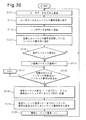
- FIG. 28 It is a flowchart of the reception process by the radio network controller shown in FIG. 28 is a flowchart (part 1) of the rearrangement process performed by the wireless network control device shown in FIG. 27; 28 is a flowchart (part 2) of the rearrangement process by the wireless network control device shown in FIG.
- FIG. 25 is a block diagram of the mobile station shown in FIG. 24. It is the 2nd example of the block diagram of the base station shown in FIG. Fig. 25 is an operation flowchart of the mobile station shown in Fig. 24. It is explanatory drawing of the 2nd example of operation
- FIG. 3 is a configuration diagram of a first example of the disclosed communication system.
- the communication system 1 includes a first packet transmitter / receiver 2, a second packet transmitter / receiver 3, and a third packet transmitter / receiver 4.
- the first and second packet transmitting / receiving apparatuses 2 and 3 may be a base station and a radio network controller as in other embodiments described below. Further, the first and second packet transmitting / receiving apparatuses 2 and 3 may be a mobile station and a base station as in other embodiments described below. That is, the first and second packet transmitting / receiving apparatuses 2 and 3 may be in a relationship of a lower apparatus and an upper apparatus.
- the first and second packet transmitting / receiving apparatuses 2 and 3 may be base stations or radio network controllers. That is, the first and second packet transmission / reception devices 2 and 3 do not have to be related to the lower device and the higher device.
- FIG. 4 is a first example of a hardware configuration diagram of the first packet transmitting / receiving apparatus 2 shown in FIG.
- the first packet transmitting / receiving apparatus 2 includes a processor 10, a program storage unit 12 that stores a control program 11, a memory 13, a packet acquisition unit 14, a communication unit 15, a transmission buffer 16, and a reception buffer 17.
- the processor 10 is realized by a data processor such as a CPU, and controls the operation of the first packet transmitting / receiving apparatus 2 by executing a control program 11 stored in the program storage unit 12.
- the program storage unit 12 may store an application program that generates user data by being executed by the processor 10.
- the memory 13 stores data necessary for execution of the control program 11 and application programs, and also stores temporary data generated when these programs are executed.
- the packet acquisition unit 14 acquires a packet transmitted from the first packet transmission / reception device 2 to the second packet transmission / reception device 3.
- Each packet acquired by the packet acquisition unit 14 has a sequence number indicating the order of the packets.
- the sequence number may be embedded in each packet.
- the packet acquisition unit 14 may acquire a packet by receiving a packet from another communication device.
- the packet acquisition unit 14 may be a software module that acquires a packet obtained by dividing user data generated by an application program executed by the processor 10, for example.
- the communication unit 15 transmits / receives data to / from the second packet transmitting / receiving device 3. For example, the communication unit 15 transmits the packet acquired by the packet acquisition unit 14 to the second packet transmitting / receiving apparatus 3.
- the transmission buffer 16 temporarily holds data transmitted to the second packet transmitting / receiving apparatus 3 until the communication unit 15 accepts the data.
- the reception buffer 17 temporarily holds data received from the second packet transmitting / receiving device 3 by the communication unit 15.
- FIG. 5 is a first example of a block diagram of the first packet transmitting / receiving apparatus 2 shown in FIG.
- the processor 10 executes the control program 11 stored in the program storage unit 12, the functions of the packet transmission unit 20, the transmitted packet instruction information generation unit 21, and the transmitted packet instruction information transmission unit 23 are realized.
- the packet transmission unit 20 performs a process of transmitting the packet acquired by the packet acquisition unit 14 to the second packet transmitting / receiving apparatus 3.
- the packet transmission unit 20 inputs a packet to be transmitted to the second packet transmission / reception device 3 to the transmission buffer 16, and the communication unit 15 transmits the packet stored in the transmission buffer 16 to the second packet transmission / reception device 3.
- the transmitted packet instruction information generation unit 21 inputs the packet acquired by the packet acquisition unit 14.
- the transmitted packet instruction information generation unit 21 considers that the packet received from the packet acquisition unit 14 has been transmitted by the packet transmission unit 20, and has transmitted the packet instruction information indicating the packet transmitted by the packet transmission unit 20. Is generated.
- the transmitted packet instruction information may identify the packet transmitted by the packet transmission unit 20 by the sequence number of the transmitted packet.
- the transmitted packet instruction information used in the description in the present specification includes a set of sequence numbers including a series of sequence numbers in which the sequence numbers of the packets transmitted by the packet transmitter 20 are arranged in the order of transmission of the packets. It is.
- the transmitted packet instruction information generation unit 21 extracts the sequence number embedded in each packet from each packet acquired from the packet acquisition unit 14.
- the transmitted packet instruction information generation unit 21 stores the extracted sequence number in the memory 13.
- the transmitted packet instruction information generation unit 21 adds a sequence number of each packet to the sequence number sequence stored in the memory 13 each time the sequence number is extracted. Generate a sequence of numbers.
- the transmitted packet instruction information generation unit 21 reads a sequence number sequence stored in the memory 13 at a transmission timing described later, and transmits transmitted packet instruction information including the sequence number sequence to a transmitted packet instruction information transmission unit. To 23.
- the transmitted packet instruction information transmitting unit 23 performs a process of transmitting the transmitted packet instruction information received from the transmitted packet instruction information generating unit 21 to the second packet transmitting / receiving apparatus 3.
- the transmitted packet instruction information transmitting unit 23 inputs the transmitted packet instruction information to the transmission buffer 16, and the communication unit 15 transmits the transmitted packet instruction information stored in the transmission buffer 16 to the second packet transmitting / receiving apparatus 3. .
- FIG. 6 is a hardware configuration diagram of the second packet transmitting / receiving apparatus 3 shown in FIG.
- the second packet transmitting / receiving apparatus 3 includes a processor 30, a program storage unit 32 that stores a control program 31, a memory 33, a first communication unit 34, a first reception buffer 35, and a first transmission buffer 36.
- the second packet transmitting / receiving apparatus 3 includes a second communication unit 37, a second transmission buffer 38, a second reception buffer 39, and a rearrangement buffer 40.
- the processor 30 is realized by a data processor such as a CPU, and controls the operation of the second packet transmitting / receiving apparatus 3 by executing a control program 31 stored in the program storage unit 32.
- the memory 33 stores data necessary for executing the program such as the control program 31, and also stores temporary data generated when these programs are executed.
- the first communication unit 34 transmits / receives data to / from the first packet transmitting / receiving device 2. For example, the first communication unit 34 receives a packet transmitted by the first packet transmitting / receiving apparatus 2. For example, the first communication unit 34 receives the transmitted packet instruction information transmitted by the first packet transmitting / receiving apparatus 2.
- the first reception buffer 35 temporarily holds data received from the first packet transmitting / receiving device 2 by the first communication unit 34.
- the first transmission buffer 36 temporarily holds data transmitted from the second packet transmission / reception device 3 to the first packet transmission / reception device 2 until the first communication unit 34 receives the data.
- the second communication unit 37 transmits / receives data to / from the third packet transmitting / receiving device 4.
- the second communication unit 37 transmits the packets received from the first packet transmitting / receiving device 2 and rearranged in the order of sequence numbers by the rearrangement processing by the processor 30 described below to the third packet transmitting / receiving device 4.
- the second reception buffer 39 temporarily holds data received from the third packet transmitting / receiving device 4 by the second communication unit 37.
- the second transmission buffer 38 temporarily holds data transmitted from the second packet transmission / reception device 3 to the third packet transmission / reception device 4 until the second communication unit 37 accepts the data.
- the rearrangement buffer 40 is a buffer used for saving received packets from the first reception buffer 35 as necessary during rearrangement processing of packets received from the first packet transmitting / receiving apparatus 2.
- FIG. 7 is a first example of a block diagram of the second packet transmitting / receiving apparatus 3 shown in FIG.
- the processor 30 executes the control program 31 stored in the program storage unit 32, the functions of the packet reception unit 50, the transmitted packet instruction information reception unit 51, the rearrangement processing unit 52, and the packet transmission unit 53 are realized.
- the packet receiving unit 50 performs reception processing of the received packet received by the first communication unit 34 and stored in the first reception buffer 35.
- the transmitted packet instruction information receiving unit 51 performs reception processing of the transmitted packet instruction information received by the first communication unit 34 and stored in the first reception buffer 35.
- the rearrangement processing unit 52 performs rearrangement processing for rearranging the packets received from the first packet transmitting / receiving apparatus 2 in the order of the sequence numbers of the respective packets. At the time of the rearrangement process, the rearrangement processing unit 52 saves the packet read from the first reception buffer 35 in the rearrangement buffer 40 as necessary.
- the packet transmission unit 53 performs processing for transmitting packets to the third packet transmitting / receiving device 4 in the order rearranged by the rearrangement processing unit 52.
- the packet transmission unit 53 inputs a packet transmitted to the third packet transmission / reception device 4 to the second transmission buffer 38, and the second communication unit 37 transmits the packet stored in the second transmission buffer 38 to the third packet transmission / reception device 4 to send.
- FIG. 8 is a first example of an operation flowchart of the first packet transmitting / receiving apparatus 2 shown in FIG.
- the packet acquisition unit 14 acquires a packet transmitted from the first packet transmission / reception device 2 to the second packet transmission / reception device 3.
- the acquired packet may be a packet that stores user data received from another communication device or a packet that stores user data generated by an application program executed by the processor 10.
- step S2 the transmitted packet instruction information generation unit 21 acquires the sequence number embedded in the packet acquired in step S1.
- step S3 the packet transmitter 20 transmits the packet acquired in step S1 to the second packet transmitting / receiving apparatus 3.
- step S4 the transmitted packet instruction information generation unit 21 stores the sequence number acquired in step S2 in the memory 13.
- the transmitted packet instruction information generation unit 21 newly stores it after the sequence number already stored in the memory 13. Add a sequence number.
- step S5 the transmitted packet instruction information generation unit 21 determines whether or not the sequence number acquired in step S2 is an expected sequence number.
- the “expected sequence number” is the sequence number that has the earliest transmission order among the sequence numbers of untransmitted packets. In this embodiment, it is assumed that the transmission order is determined in ascending order. In this case, the “expected sequence number” is the smallest sequence number among the sequence numbers among the untransmitted packets. If for some reason a packet is not transmitted in the order of the sequence number and a packet that is overtaken by a subsequent packet is generated, the sequence number of the overtaken packet is the smallest sequence number.
- step S5 N
- the processor 10 returns the process to step S1.
- the transmitted packet instruction information generation unit 21 stores in the memory 13 a sequence number sequence of transmitted packets having a sequence number after the expected sequence number.
- step S6 sets the value of the index variable i to (expected Set to sequence number + 1).
- steps S7 and S8 the transmitted packet instruction information generation unit 21 searches for the minimum expected sequence number that is not stored in the memory 13. That is, in step S7, the transmitted packet instruction information generation unit 21 determines whether or not a sequence number equal to the value of the index variable i is stored in the memory 13. As long as the sequence number equal to the value of the index variable i is stored in the memory 13 (step S7: Y), the transmitted packet instruction information generation unit 21 increments the value of the index variable i by 1 in step S8. Steps S7 and S8 are repeated.
- step S9 the transmitted packet instruction information generation unit 21 continues the sequence from the expected sequence number to (i-1). Generate transmitted packet instruction information including a number.
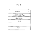
- FIG. 9 is a diagram showing a frame format of the transmitted packet instruction information.
- the transmitted packet instruction information includes a header part (Header CRC), an FT field, a Control Frame Type field, a notification TSN number field, and one or more TSN # 0 to TSN # (n-1) fields.
- the value of the FT field indicates whether this frame is a control frame or a data frame.
- the value of the Control Frame Type field indicates that this frame is transmitted packet instruction information for notifying sequence data.
- the value of the notification TSN number field indicates the total number of sequence numbers notified by the transmitted packet instruction information. Sequence numbers are stored in the TSN # 0 to TSN # (n-1) fields, respectively.
- the transmitted packet instruction information transmitting unit 23 transmits the transmitted packet instruction information to the second packet transmitting / receiving apparatus 3.
- step S10 of FIG. 8 the transmitted packet instruction information generation unit 21 deletes the sequence numbers from the expected sequence number stored in the memory 13 to (i-1).
- step S11 the transmitted packet instruction information generation unit 21 updates the value of the expected sequence number to the value of the index variable i. After that, the processor 10 returns the process to step S1.
- FIG. 10 is an explanatory diagram of the operation of the communication system 1 shown in FIG.
- each packet storing user data is shown as a square surrounded by values “1” to “5”, and each value surrounded by the square represents a sequence number of each packet.
- the transmitted packet instruction information is shown as a square surrounding the character “S”.
- the first packet transmitting / receiving apparatus 2 sequentially acquires packets having sequence numbers 1 to 5 as indicated by reference numeral 60 (step S1 in FIG. 8). At this time, it is assumed that the acquisition of the packet of sequence number 2 by the first packet transmitting / receiving apparatus 2 is delayed for some reason, and the packet of sequence number 2 is acquired after receiving the packet of sequence number 5. In this case, the sequence numbers “1”, “3”, “4”, “5”, and “2” are transmitted to the second packet transmitting / receiving apparatus 3 in the order (step S3).
- the value of the expected sequence number becomes “2” due to failure to acquire the packet of sequence number 2. Therefore, the sequence numbers “3”, “4”, and “5” are stored in the memory 13 until the first packet transmitting / receiving apparatus 2 acquires the packet with the sequence number 2.
- the transmitted packet instruction information generating unit 21 When the first packet transmitting / receiving apparatus 2 acquires the packet having the sequence number 2 (step S5: Y), the transmitted packet instruction information generating unit 21 generates the transmitted packet instruction information S including the sequence numbers 2 to 5 (step S5). S9).
- the transmitted packet instruction information S may have sequence numbers 2 to 5 arranged according to the packet transmission order. For example, in this example, the sequence numbers 2 to 5 stored in the transmitted packet instruction information S are arranged in the order of “3”, “4”, “5”, “2”.
- Reference numeral 61 indicates a state in which the transmitted packet instruction information S is transmitted to the second packet transmitting / receiving apparatus 3 after the packet having the sequence number “2”.
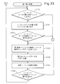
- FIG. 11 is a flowchart of the reception process by the second packet transmitting / receiving apparatus 3 shown in FIG.
- the first communication unit 34 of the second packet transmitting / receiving apparatus 3 receives the packet transmitted from the first packet transmitting / receiving apparatus 2 and / or the transmitted packet instruction information.
- the first communication unit 34 stores the data received in step S20 in the first reception buffer 35 in the order of reception.
- the second packet transmitting / receiving apparatus 3 stores the data received from the first packet transmitting / receiving apparatus 2 in the first receiving buffer 35 by repeating steps S20 and S21.
- the rearrangement processing unit 52 shown in FIG. 7 rearranges the packets received from the first packet transmission / reception device 2 and stored in the first reception buffer 35 in the order of the sequence numbers of the respective packets, and then transmits and receives the third packet. Transfer to device 4. 12 and 13 are flowcharts of the rearrangement process by the second packet transmitting / receiving apparatus 3 shown in FIG.
- step S30 the rearrangement processing unit 52 determines whether there is transmitted packet instruction information stored in the first reception buffer 35. When there is no transmitted packet instruction information stored in the first reception buffer 35 (step S30: N), the rearrangement processing unit 52 proceeds to step S37 (reference number A). If there is transmitted packet instruction information stored in the first reception buffer 35 (step S30: Y), the rearrangement processing unit 52 proceeds to step S31.
- step S31 the rearrangement processing unit 52 takes out the transmitted packet instruction information from the first reception buffer 35.
- step S32 the rearrangement processing unit 52 determines whether or not the expected sequence number is included in the sequence number indicated by the extracted transmitted packet instruction information.
- the “expected sequence number” is the smallest sequence number among the untransmitted packets and the rearrangement processing is still performed for the subsequent packets. This is the sequence number of the packet that has not been subjected to the reordering process by the unit 52.
- step S32: N When the expected sequence number is not included in the sequence number indicated by the transmitted packet instruction information (step S32: N), the rearrangement processing unit 52 proceeds to step S37 (reference number A). When the expected sequence number is included in the sequence number indicated by the transmitted packet instruction information (step S32: Y), the rearrangement processing unit 52 proceeds to step S33.
- step S33 the packet receiving unit 50 takes out the packet having the expected sequence number from the first reception buffer 35.
- step S34 the packet transmission unit 53 transmits the packet extracted in step S33 to the third packet transmitting / receiving apparatus 4.
- step S35 the rearrangement processing unit 52 updates the expected sequence number by incrementing the expected sequence number by one.
- step S36 the rearrangement processing unit 52 determines whether or not the updated expected sequence number is included in the sequence number indicated by the transmitted packet instruction information.
- the rearrangement processing unit 52 returns the process to step S33.
- the processor 30 repeatedly executes steps S33 to S36.
- the processor 30 can take out the packets of the sequence numbers that are consecutive from the first reception buffer 35 in accordance with the order of the sequence numbers and transmit them to the third packet transmitting / receiving apparatus 4. That is, by taking out the packets from the first reception buffer 35 in the order of the sequence numbers, the rearrangement processing unit 52 can perform the rearrangement process without using the rearrangement buffer.
- step S36: N the processor 30 returns the process to step S30.
- step S37 the rearrangement processing unit 52 determines whether or not the received packet is stored in the first reception buffer 35. If there is a received packet (step S37: Y), the rearrangement processing unit 52 proceeds to step S38. When there is no received packet (step S37: N), the rearrangement processing unit 52 proceeds to step S44.
- step S ⁇ b> 38 the rearrangement processing unit 52 saves the packet in the first reception buffer 35 to the rearrangement buffer 40 by copying the packet extracted from the first reception buffer 35 by the packet reception unit 50 to the rearrangement buffer 40. To do.
- the rearrangement processing unit 52 stores newly stored packets in addition to the already stored packets.
- step S39 the rearrangement processing unit 52 determines whether or not the sequence number of the packet saved in the rearrangement buffer 40 in step S38 is the same as the expected sequence number.
- the rearrangement processing unit 52 moves the process to step S40.
- step S40 the rearrangement processing unit 52 transmits one or more consecutive packets including the packet of the expected sequence number among the packets stored in the rearrangement buffer 40 to the third packet transmitting / receiving apparatus 4.
- step S41 the rearrangement processing unit 52 updates the value of the expected sequence number to (the maximum value of the sequence number of the packet transmitted in S40 + 1).
- step S42 the rearrangement processing unit 52 determines whether the rearrangement timer is running.
- the rearrangement timer may be a software timer realized by the processing of the processor 30, for example. Time measurement by the reordering timer starts when a packet having a sequence number that is not the expected sequence number is saved in the empty reordering buffer 40.
- the rearrangement timer is a timer used for transmitting a packet remaining in the rearrangement buffer 40 to the third packet transmitting / receiving apparatus 4 when a predetermined time or more has elapsed after the packet is saved in the rearrangement buffer 40. .
- step S42 If it is determined in step S42 that the reordering timer is not activated (step S42: N), the reordering unit 52 proceeds to step S43.
- step S43 the rearrangement processing unit 52 activates the rearrangement timer and starts time measurement by the rearrangement timer. Thereafter, the rearrangement processing unit 52 proceeds to step S44. If it is determined in step S42 that the rearrangement timer has already been started (step S42: Y), the rearrangement processing unit 52 proceeds to step S44.
- step S44 the rearrangement processing unit 52 determines whether the rearrangement timer is running. When the reordering timer is not activated (step S44: N), the processor 30 returns the process to step S30 (reference numeral B). When the rearrangement timer is activated (step S44: Y), the rearrangement processing unit 52 proceeds to step S45.
- step S45 the rearrangement processing unit 52 determines whether or not the time measured by the rearrangement timer has exceeded a predetermined time, that is, whether or not the time measured by the rearrangement timer has timed out.
- a predetermined time that is, whether or not the time measured by the rearrangement timer has timed out.
- step S46 the rearrangement processing unit 52 transmits all the packets stored in the rearrangement buffer 40 to the third packet transmitting / receiving apparatus 4.
- step S47 the rearrangement processing unit 52 updates the value of the expected sequence number to (the maximum value of the sequence number of the packet transmitted in S46 + 1).
- step S48 the rearrangement processing unit 52 stops the rearrangement timer. Thereafter, the processor 30 returns the process to step S30 (reference numeral B).
- step S45 when the time measured by the rearrangement timer has not timed out (step S45: N), the rearrangement processing unit 52 proceeds to step S49.
- step S49 the rearrangement processing unit 52 increases the measurement value of the rearrangement timer by a predetermined time step and updates the measurement value. Thereafter, the processor 30 returns the process to step S30 (reference numeral B).
- the first packet transmitting / receiving apparatus 2 transmits the packets including the sequence numbers 2 to 5 after transmitting the packets in the order of the sequence numbers “1”, “3”, “4”, “5”, “2”.
- the completed packet instruction information S is transmitted.
- the first reception buffer 35 of the second packet transmitting / receiving apparatus 3 stores packets arranged in the order of reception, that is, in the order of sequence numbers “1”, “3”, “4”, “5”, “2”. Thereafter, the transmitted packet instruction information S is stored.
- the sequence numbers 2 to 5 stored in the transmitted packet instruction information S are arranged in the order of “3”, “4”, “5”, “2”.
- the processor 30 may not be able to start processing this packet immediately.
- this packet is processed before the processing order of this packet arrives. Is considered to be completed.
- the rearrangement processing unit 52 of the second packet transmitting / receiving apparatus 3 receives the subsequent packet of the sequence numbers “2” to “5” and the transmitted packet instruction information S, and then receives the sequence number “1”. Start processing.
- FIG. 10 shows a state where the rearrangement buffer 40 is empty. Such a state occurs when the process does not proceed to step S37 and subsequent steps shown in FIG. 13 and the packet is not saved in the rearrangement buffer 40.
- the sequence number of the packet taken out from the first reception buffer 35 matches the expected sequence number, and the rearrangement processing unit 52 repeats steps S30 to S36 shown in FIG. Therefore, the expected sequence number is “2” when the rearrangement processing unit 52 extracts the transmitted packet instruction information S from the first reception buffer 35 after the packet with the sequence number “1”.
- the rearrangement processing unit 52 Based on the transmitted packet instruction information S (step S31 in FIG. 12), the rearrangement processing unit 52 receives the packet with the expected sequence number “2” and the subsequent sequence numbers “3” to “5” from the first reception. It can be known that it is stored in the buffer 35. For this reason, in steps S33 to S36, the rearrangement processing unit 52 can take out the consecutive packets having the sequence numbers “2” to “5” from the first reception buffer 35 in the order of the sequence numbers.
- the rearrangement processing unit 52 causes the packet transmission unit 53 to transmit packets according to the order extracted from the first reception buffer 35.
- the second transmission buffer 38 stores packets waiting for the transmission order.
- the order of the packets stored in the second transmission buffer 38 follows the order of the sequence numbers.
- the squares denoted by reference numeral 63 indicate the storage positions in the second transmission buffer 38. In the figure, the transmission order is earlier in the data stored in the upper cells.
- the number written in each square indicates the sequence number of the stored packet.
- the character “x” indicates that the preceding packet is stored, the character “e” indicates an empty storage position, and the character “a” follows the packets of the sequence numbers “2” to “5”. Indicates an available storage location.
- the squares indicated by reference numeral 64 mean time charts of packets transmitted from the second packet transmitting / receiving device 3 to the third packet transmitting / receiving device 4.
- the data stored in the square on the right side has a higher transmission order.
- the numbers described in squares indicate the sequence number of the packet.
- the letter “x” indicates the preceding packet
- the letter “e” indicates an empty time slot
- the letter “a” indicates an available time slot after the packets with sequence numbers “2” to “5”. .
- the notation used in FIG. 10 is also used in FIG. 29, FIG. 31, and FIG.
- the rearrangement processing unit 52 performs packet rearrangement processing without saving the packets in the rearrangement buffer 40.
- the rearrangement processing unit 52 can read the packet from the first reception buffer 35 according to the sequence number order. That is, even if a packet with an older sequence number is received after a packet with a lower sequence number, the packet with the older sequence number can be read out from the first reception buffer 35 first and transmitted.
- the packets are taken out from the first reception buffer 35 in the received order. For this reason, when the order of the sequence numbers does not match the order of reception, the transmission processing of these packets is performed until all subsequent packets received earlier than the packets with the older sequence numbers are saved in the rearrangement buffer 40. Must be delayed.
- the rearrangement process in steps S33 to S36 can prevent a delay in the packet transmission process that occurs in the rearrangement process using the rearrangement buffer 40 as described above.
- Reference numeral 66 in FIG. 10 indicates that the delay in transmission processing of the packets with the sequence numbers “2” to “5” can be reduced and the available time slots can be increased.
- the packet saved in the rearrangement buffer 40 when the packet having the expected sequence number is taken out from the first reception buffer 35 is immediately transmitted to the third packet.
- the data is transmitted to the transmission / reception device 4. For this reason, a transmission burst is generated, and a load on the third packet transmitting / receiving apparatus 4 is generated.
- the transmission burst causes data loss. For this reason, the rearrangement process using the rearrangement buffer 40 causes a reduction in communication throughput in the communication system 1.
- steps S33 to S36 the rearrangement processing unit 52 alternately performs the packet reading process from the first reception buffer 35 and the packet transmission process.
- Such a process of alternately performing reading and transmission is the same as the process in the case where the rearrangement process does not occur, and therefore the transmission interval of each packet does not greatly differ from the case in which the rearrangement process does not occur. Therefore, the rearrangement process performed in steps S33 to S36 can prevent transmission bursts.
- Reference numeral 65 in FIG. 10 indicates that the transmission interval of packets with sequence numbers “1” to “5” is maintained and transmission bursts are prevented.
- the rearrangement processing unit 52 determines the storage order of each packet in the first reception buffer 35 based on the transmitted packet instruction information. be able to. In this case, the rearrangement processing unit 52 can take out a packet having a desired sequence number from the first reception buffer 35 without referring to the sequence number embedded in each packet.
- the rearrangement process using the rearrangement buffer for example, after a packet that is user data is stored in the reception buffer, the stored packet is copied to the rearrangement buffer, so that the processing of the processor of the reception apparatus increases. For this reason, there is a risk of processing delay of user data and failure of the data transmission function due to overload of the processor of the receiving apparatus.
- the second packet transmitting / receiving apparatus 3 when the processing of the second packet transmitting / receiving apparatus 3 is delayed and a large number of packets are accumulated in the first reception buffer 35, the transmitted packet instruction is also added to these packets. Information is also stored in the first reception buffer 35. Therefore, the second packet transmitting / receiving apparatus 3 can perform the rearrangement process when taking out the packet from the first reception buffer 35 with reference to the transmitted packet instruction information. Since overloading of the processor 30 due to the use of the rearrangement buffer can be prevented, the above-described problems such as user data processing delay and data transmission function failure can be solved.
- bursts of data transmitted from the second packet transmitting / receiving apparatus 3 can be prevented.
- the present embodiment can solve problems such as induction of functional failure of the communication system 1 due to communication bursts and missing user data due to shaping.
- transmission power may be suppressed in radio communication between the mobile station and the base station in order to effectively use radio resources.
- the HARQ retransmission rate increases, the sequence number order does not match the reception order, and the load of user data rearrangement processing in the radio network controller increases.
- the rearrangement process of the present embodiment can contribute to reducing the load of the user data rearrangement process in the radio network controller.
- FIG. 14 is a second example of an operation flowchart of the first packet transmitting / receiving apparatus 2 shown in FIG.
- the first packet transmitting / receiving apparatus 2 transmits the transmitted packet instruction information to the second packet transmitting / receiving apparatus 3 at a constant cycle.
- the first packet transmitting / receiving apparatus 2 sequentially stores the acquired packet sequence numbers in the memory 13 during a predetermined transmission period. At each periodic transmission time, the first packet transmitting / receiving apparatus 2 transmits transmitted packet instruction information including the sequence number stored in the memory 13 to the second packet transmitting / receiving apparatus 3. Specific processing will be described with reference to FIG.
- step S50 the packet acquisition unit 14 acquires a packet in the same manner as in step S1 shown in FIG.
- step S51 the transmitted packet instruction information generation unit 21 acquires the sequence number embedded in the packet acquired in step S50.
- step S52 the packet transmission unit 20 transmits the packet acquired in step S50 to the second packet transmitting / receiving apparatus 3.
- step S53 the transmitted packet instruction information generation unit 21 stores the sequence number acquired in step S51 in the memory 13, as in step S4 shown in FIG.
- step S54 the transmitted packet instruction information generation unit 21 determines whether or not the current time is a periodic transmission time for transmitting the transmitted packet instruction information. If the current time is not a periodic transmission time (step S54: N), the processor 10 returns the process to step S50. By repeating the processing of steps S50 to S54 for a predetermined period, the transmitted packet instruction information generating unit 21 stores a sequence number sequence of transmitted packets in the memory 13.
- step S54 When the current time is a periodic transmission time (step S54: Y), the transmitted packet instruction information generation unit 21 in step S55 transmits a transmitted packet instruction including all sequence numbers stored in the memory 13. Generate information.
- the transmitted packet instruction information transmitting unit 23 transmits the transmitted packet instruction information to the second packet transmitting / receiving apparatus 3.
- step S56 the transmitted packet instruction information generation unit 21 deletes the sequence number stored in the memory 13. After that, the processor 10 returns the process to step S50.
- the transmitted packet instruction information generation unit 21 can generate transmitted packet instruction information by a relatively simple process of periodically counting sequence numbers. For this reason, this embodiment can be realized without imposing a heavy load on the processing processor 10 of the first packet transmitting / receiving apparatus 2.
- FIG. 15 is a second example of the block diagram of the first packet transmitting / receiving apparatus 2 shown in FIG. 4, and FIG. 16 is a second example of the block diagram of the second packet transmitting / receiving apparatus 3 shown in FIG.
- the first packet transmitting / receiving apparatus 2 transmits transmitted packet instruction information to the second packet transmitting / receiving apparatus 3 in response to a request from the second packet transmitting / receiving apparatus 3.
- the same reference numerals are assigned to the same components as those shown in FIG. 5. Also, the processor 10 shown in FIG. 4 executes the control program 11 stored in the program storage unit 12, thereby realizing the function of the transmitted packet instruction information request signal receiving unit 24.
- the same constituent elements as those shown in FIG. 7 are denoted by the same reference numerals. Further, the processor 30 shown in FIG. 6 executes the control program 31 stored in the program storage unit 32, thereby realizing the function of the transmitted packet instruction information request signal transmission unit 54.
- the transmitted packet instruction information request signal transmitting unit 54 generates a transmitted packet instruction information request signal for requesting the first packet transmitting / receiving apparatus 2 to transmit the transmitted packet instruction information, and transmits the generated packet instruction information request signal to the first packet transmitting / receiving apparatus 2. Perform the process.
- the transmitted packet instruction information request signal transmitter 54 may periodically transmit a transmitted packet instruction information request signal to the first packet transmitting / receiving apparatus 2.
- the transmitted packet instruction information request signal transmission unit 54 may transmit the transmitted packet instruction information request signal to the first packet transmitting / receiving apparatus 2 in accordance with the instruction of the rearrangement processing unit 52.
- the rearrangement processing unit 52 transmits the transmitted packet instruction information request signal to the transmitted packet instruction information request signal when the processor 30 ends the processing of the packet instructed by the already received transmitted packet instruction information.
- the transmission unit 54 may be instructed.
- the transmitted packet instruction information request signal receiving unit 24 shown in FIG. 15 receives the transmitted packet instruction information request signal transmitted from the second packet transmitting / receiving apparatus 3.
- the packet instruction information request signal receiving unit 24 receives the transmitted packet instruction information request signal
- the transmitted packet instruction information generating unit 21 and the transmitted packet instruction information transmitting unit 23 generate and transmit the transmitted packet instruction information. Do.
- FIG. 17 is a third example of an operation flowchart of the first packet transmitting / receiving apparatus 2 shown in FIG.
- the packet acquisition unit 14 acquires a packet similarly to step S1 shown in FIG.
- the transmitted packet instruction information generation unit 21 acquires the sequence number embedded in the packet acquired in step S60.
- the packet transmission unit 20 transmits the packet acquired in step S60 to the second packet transmitting / receiving apparatus 3.
- the transmitted packet instruction information generation unit 21 stores the sequence number acquired in step S61 in the memory 13, as in step S4 shown in FIG.
- step S64 the transmitted packet instruction information generating unit 21 determines whether the transmitted packet instruction information request signal receiving unit 24 has received the transmitted packet instruction information request signal. If the transmitted packet instruction information request signal has not been received (step S64: N), the processor 10 returns the process to step S60. By repeating the processing of steps S60 to S64 until the transmitted packet instruction information request signal is received, the transmitted packet instruction information generation unit 21 stores a sequence number sequence of transmitted packets in the memory 13. .
- step S64 When the transmitted packet instruction information request signal is received (step S64: Y), the transmitted packet instruction information generation unit 21 in step S65 transmits the transmitted packet including all sequence numbers stored in the memory 13. Generate instruction information.
- the transmitted packet instruction information transmitting unit 23 transmits the transmitted packet instruction information to the second packet transmitting / receiving apparatus 3.
- step S66 the transmitted packet instruction information generation unit 21 deletes the sequence number stored in the memory 13. After that, the processor 10 returns the process to step S60.
- the transmitted packet instruction information can be transmitted according to the demand of the second packet transmitting / receiving apparatus 3 that receives the packet, so that the transmitted packet instruction information is efficiently generated and transmitted. Is possible.
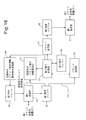
- FIG. 18 is a third example of a functional block diagram of the first packet transmitting / receiving apparatus 2 shown in FIG.
- the first packet transmission / reception device 2 transmits transmitted packet instruction information to the second packet transmission / reception device 3 when a predetermined condition is satisfied after detection of the missing packet.
- the “missing packet” refers to a packet transmitted after the subsequent packet when the packet is not transmitted from the first packet transmitting / receiving apparatus 2 to the second packet transmitting / receiving apparatus 3 in the order of the sequence numbers.
- the processor 10 illustrated in FIG. 4 executes the control program 11 stored in the program storage unit 12, thereby realizing the functions of the missing packet detection unit 25 and the transmission availability determination unit 26.
- the missing packet detector 25 detects the occurrence of a missing packet. For example, the missing packet detector 25 may detect the occurrence of a missing packet by determining whether or not the sequence numbers stored in the memory 13 are discontinuous.
- the transmission availability determination unit 26 determines whether or not a predetermined condition is satisfied after the missing packet detection unit 25 detects the missing packet. When the transmission possibility determination unit 26 determines that a predetermined condition is satisfied, the transmitted packet instruction information generation unit 21 and the transmitted packet instruction information transmission unit 23 generate and transmit transmitted packet instruction information.
- the predetermined condition may be that a predetermined time has elapsed since detection of a missing packet, or that a predetermined number of packets have been transmitted since detection of a missing packet.
- FIG. 19 is a fourth example of an operation flowchart of the first packet transmitting / receiving apparatus 2 shown in FIG.
- the packet acquisition unit 14 acquires a packet similarly to step S1 shown in FIG.
- the transmitted packet instruction information generation unit 21 acquires the sequence number embedded in the packet acquired in step S70.
- the packet transmission unit 20 transmits the packet acquired in step S70 to the second packet transmitting / receiving apparatus 3.
- the transmitted packet instruction information generation unit 21 stores the sequence number acquired in step S81 in the memory 13 as in step S4 shown in FIG.
- the transmission permission / inhibition determination unit 26 refers to the value of the packet loss flag and determines whether or not it is stored that a lost packet is detected.
- the packet loss flag is a variable that can be referred to and changed by the processor 10 and can take a value “T” indicating that a missing packet has occurred and a value “F” indicating that a missing packet has not occurred.
- step S74: N If the value of the packet loss flag is not “T” (step S74: N), the processor 10 moves the process to step S75.
- step S75 the missing packet detector 25 detects whether or not a missing packet has occurred. If a missing packet has occurred (step S75: Y), in step S76, the missing packet detector 25 substitutes the value “T” for the packet loss flag. After that, the processor 10 moves the process to step S70.
- step S75 If there is no missing packet in the determination in step S75 (step S75: N), the processor 10 moves the process to step S70.
- step S74: Y When the value of the packet loss flag is “T” (step S74: Y), the processor 10 moves the process to step S77.
- step S77 the transmission permission determination unit 26 determines whether or not the above-described predetermined condition is satisfied.
- the transmitted packet instruction information generation unit 21 transmits all sequence numbers stored in the memory 13 in step S78. End packet instruction information is generated.
- the transmitted packet instruction information transmitting unit 23 transmits the transmitted packet instruction information to the second packet transmitting / receiving apparatus 3.
- step S79 the transmitted packet instruction information generation unit 21 deletes the sequence number stored in the memory 13.
- step S80 the transmission permission / inhibition determining unit 26 substitutes the value “F” for the packet loss flag. After that, the processor 10 returns the process to step S70.
- the transmission permission determination unit 26 determines that the predetermined condition is not satisfied in the determination in step S77 (step S77: N), the processor 10 returns the process to step S70.
- the transmitted packet instruction information can be transmitted without determining whether the lost packet has been transmitted. For this reason, this embodiment can be realized without imposing a heavy load on the processing processor 10 of the first packet transmitting / receiving apparatus 2.
- FIG. 20 is a second example of a hardware configuration diagram of the first packet transmitting / receiving apparatus 2 shown in FIG.
- the first packet transmission / reception device 2 performs a retransmission control process for packets to be transmitted to the second packet transmission / reception device 3. Therefore, the first packet transmitting / receiving apparatus 2 includes a retransmission control unit 18.
- the retransmission control executed between the first packet transmission / reception device 2 and the second packet transmission / reception device 3 may be HARQ control, for example.
- the first packet transmitting / receiving device 2 determines whether each packet has been transmitted to the second packet transmitting / receiving device 3 based on the acknowledge signal received from the second packet transmitting / receiving device 3.
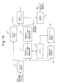
- FIG. 21 is a block diagram of the first packet transmitting / receiving apparatus 2 shown in FIG.
- the processor 10 shown in FIG. 4 executes the control program 11 stored in the program storage unit 12, the functions of the ACK acquisition unit 27 and the sequence number acquisition unit 28 are realized.
- the ACK acquisition unit 27 acquires an acknowledge signal received from the second packet transmitting / receiving apparatus 3 for each packet by the retransmission control performed by the retransmission control unit 18.
- the sequence number acquisition unit 28 acquires the sequence number of the packet from the acknowledge signal acquired by the ACK acquisition unit 27 for each packet.
- the transmitted packet instruction information generation unit 21 inputs the sequence number of the packet transmitted by the packet transmission unit 20 from the sequence number acquisition unit 28, and the packet transmitted by the packet transmission unit 20 according to the input sequence number Is identified.
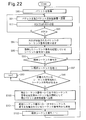
- FIG. 22 is an example of an operation flowchart of the first packet transmitting / receiving apparatus 2 shown in FIG.
- the packet acquisition unit 14 acquires a packet similarly to step S1 shown in FIG.
- the packet transmission unit 20 transmits the packet acquired in step S90 to the second packet transmitting / receiving apparatus 3.
- the communication unit 15 receives an acknowledge signal (ACK) or a negative acknowledgment signal (NACK) from the second packet transmitting / receiving apparatus 3 for the packet transmitted in step S91.
- ACK acknowledge signal
- NACK negative acknowledgment signal
- step S93 the processor 10 determines whether or not the communication unit 15 has received an acknowledge signal.
- the processor 10 receives a negative response signal (S93: N)
- the processor 10 returns the process to step S91 and retransmits the packet.
- the processor 10 moves the process to step S94.
- step S94 the ACK acquisition unit 27 acquires an acknowledge signal from the reception buffer 17. Then, the sequence number acquisition unit 29 extracts the sequence number of the packet for which the acknowledge signal is returned from the acquired acknowledge signal. The transmitted packet instruction information generation unit 21 inputs the extracted sequence number from the sequence number acquisition unit 28.
- step S95 the transmitted packet instruction information generation unit 21 stores the sequence number acquired in step S94 in the memory 13, as in step S4 shown in FIG.
- step S96 the transmitted packet instruction information generation unit 21 determines whether or not the sequence number acquired in step S94 is an expected sequence number. If the sequence number acquired in step S94 is not the expected sequence number (step S96: N), the processor 10 returns the process to step S90.
- step S97 the transmitted packet instruction information generation unit 21 sets the value of the index variable i to (expected sequence number + 1). Set.
- steps S98 and S99 the transmitted packet instruction information generation unit 21 searches for the minimum expected sequence number that is not stored in the memory 13. That is, in step S98, the transmitted packet instruction information generation unit 21 determines whether or not a sequence number equal to the value of the index variable i is stored in the memory 13. As long as a sequence number equal to the value of the index variable i is stored in the memory 13 (step S98: Y), the transmitted packet instruction information generation unit 21 increments the value of the index variable i by 1 in step S99. Steps S99 and S98 are repeated.
- step S100 the transmitted packet instruction information generation unit 21 continues the sequence from the expected sequence number to (i-1). Generate transmitted packet instruction information including a number.
- the transmitted packet instruction information transmitting unit 23 transmits the transmitted packet instruction information to the second packet transmitting / receiving apparatus 3.
- step S101 the transmitted packet instruction information generation unit 21 deletes consecutive sequence numbers from the expected sequence number stored in the memory 13 to (i-1).
- step S102 the transmitted packet instruction information generation unit 21 updates the value of the expected sequence number to the value of the index variable i. After that, the processor 10 returns the process to step S90.
- the first packet transmitting / receiving apparatus 2 can determine whether or not the packet having the expected sequence number has been transmitted more accurately.
- FIG. 23 is a configuration diagram of a second example of the disclosed communication system.
- the communication system 100 includes a mobile station (UE) 101, a base station (NodeB) 102, a radio network controller (RNC) 103, and an xGSN 104.
- the communication system 100 is a W-CDMA mobile communication system, and the communication system 100 provides an HSUPA service in the uplink from the mobile station 101 to the host device.
- the first packet transmitting / receiving apparatus 2 shown in FIG. 3 is applied to the base station 102
- the second packet transmitting / receiving apparatus 3 is applied to the radio network controller 103
- the third packet transmitting / receiving apparatus 4 is applied to the xGSN 104. explain.
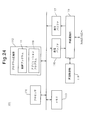
- FIG. 24 is a hardware configuration diagram of the mobile station 101 shown in FIG.
- the base station 101 includes a processor 110, a program storage unit 112 that stores a control program 111, a memory 113, a wireless communication unit 115, a transmission buffer 116, a reception buffer 117, and a retransmission control unit 118.
- the processor 110 is realized by a data processor such as a CPU, and controls the operation of the mobile station 101 by executing a control program 111 stored in the program storage unit 112.
- the program storage unit 112 may store an application program 119 that is executed by the processor 110 to generate user data.
- the memory 113 stores data necessary for the execution of the control program 111 and the application program 119, and stores temporary data generated when these programs are executed.
- the mobile station 101 divides user data generated by the application program 119 into frames having a predetermined format, and then transmits the frames to the base station 102.
- the frame may be a MAC-es PDU.
- Each frame for transmitting user data has a sequence number indicating the order of the frames. The sequence number may be embedded in each frame.
- a frame obtained by dividing user data may be simply referred to as “user data”.
- the wireless communication unit 115 has a wireless communication function with the base station 102, which is a higher-level device of the mobile station 101. For example, the wireless communication unit 115 transmits user data to the base station 102. Further, the wireless communication unit 115 receives from the base station 102 an acknowledge signal or a negative response signal for the transmitted user data.
- the transmission buffer 116 temporarily holds data transmitted to the base station 102 until the wireless communication unit 115 accepts the data.
- the reception buffer 117 temporarily holds data received from the base station 102 by the wireless communication unit 115.
- the retransmission control unit 118 performs a wireless communication retransmission control process with the base station 102 by the wireless communication unit 115.
- the retransmission control by the retransmission control unit 118 may be HARQ control, for example.
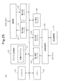
- FIG. 25 is a hardware configuration diagram of the base station 102 shown in FIG.
- the base station 102 includes a processor 120, a program storage unit 122 that stores a control program 121, a memory 123, a wireless communication unit 124, a first reception buffer 125, and a first transmission buffer 126.
- the base station 102 also includes a communication unit 127, a second transmission buffer 128, a second reception buffer 129, a rearrangement buffer 130, and a retransmission control unit 131.
- the processor 120 is realized by a data processor such as a CPU, and controls the operation of the base station 102 by executing a control program 121 stored in the program storage unit 122.
- the memory 123 stores data necessary for executing a program such as the control program 121, and also stores temporary data generated when these programs are executed.
- the wireless communication unit 124 has a wireless communication function with the mobile station 101. For example, the wireless communication unit 124 receives user data transmitted by the mobile station 101. In addition, the wireless communication unit 124 transmits an acknowledgment signal or a negative acknowledgment signal regarding user data received from the mobile station 101 to the mobile station 101.
- the first reception buffer 125 temporarily holds data received from the mobile station 101 by the wireless communication unit 124.
- the first transmission buffer 126 temporarily holds data transmitted from the base station 102 to the mobile station 101 until the wireless communication unit 124 accepts the data.
- the communication unit 127 performs data transmission / reception with the wireless network control device 103 which is a host device of the base station 101. For example, the communication unit 127 transmits user data received from the mobile station 101 to the radio network controller 103.
- the second reception buffer 129 temporarily holds data received from the radio network controller 103 by the communication unit 127.
- the second transmission buffer 128 temporarily holds data transmitted from the base station 102 to the radio network controller 103 until the communication unit 127 accepts the data.
- the retransmission control unit 131 performs a wireless communication retransmission control process with the mobile station 101 by the wireless communication unit 124.
- the rearrangement buffer 130 will be described later.
- FIG. 26 is a first example of a block diagram of the base station 102 shown in FIG.
- the processor 120 executes the control program 121 stored in the program storage unit 122, the functions of the user data transmission unit 132, the sequence data generation unit 133, and the sequence data transmission unit 135 are realized.
- the user data transmission unit 132 performs processing for transmitting the user data received from the mobile station 101 by the wireless communication unit 124 to the wireless network control device 103.
- the user data transmission unit 132 inputs a packet to be transmitted to the radio network controller 103 to the second transmission buffer 128, and the communication unit 127 transmits the packet stored in the second transmission buffer 128 to the radio network controller 103. To do.
- the sequence data generation unit 133 inputs user data received from the mobile station 101, acquires sequence numbers from these user data, and generates sequence data including these sequence numbers.
- the sequence data indicates user data transmitted by the user data transmitting unit 132, and corresponds to an example of transmitted packet instruction information in the other embodiments described above.
- the sequence data generation unit 133 includes a column n1 in which these numbers are arranged in the order of reception.
- N2, n3, and n4 may be sequence data.
- the sequence data generation unit 133 extracts the embedded sequence number from each user data received from the mobile station 101.
- the sequence data generation unit 133 stores the extracted sequence number in the memory 123.
- Each time the sequence data generation unit 133 extracts the sequence number of each user data the sequence data is added to the sequence number column stored in the memory 123 so that the sequence number is arranged in the order of reception of the user data.
- Generate a column of The sequence data generation unit 133 reads out a sequence number sequence stored in the memory 123 at a transmission timing described later, and outputs sequence data including the sequence number sequence to the sequence data transmission unit 135.
- the user data transmission unit 132 transmits user data to the radio network controller 103 in the order received from the mobile station 101
- the sequence number included in the sequence data is ordered from the base station 102 to the radio network controller 103. It is the same as the transmission order of the user data to.
- the sequence data transmission unit 135 performs a process of transmitting the sequence data generated by the sequence data generation unit 133 to the radio network controller 103.
- the sequence data transmission unit 135 inputs the sequence data to the second transmission buffer 128, and the communication unit 127 transmits the sequence data stored in the second transmission buffer 128 to the radio network controller 103.
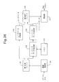
- FIG. 27 is a hardware configuration diagram of the radio network controller 103 shown in FIG.
- the wireless network control apparatus 103 includes a processor 140, a program storage unit 142 that stores a control program 141, a memory 143, a first communication unit 144, a first reception buffer 145, and a first transmission buffer 146.
- the radio network controller 103 includes a second communication unit 147, a second transmission buffer 148, a second reception buffer 149, and a rearrangement buffer 150.
- the processor 140 is realized by a data processor such as a CPU, and controls the operation of the radio network controller 103 by executing a control program 141 stored in the program storage unit 142.
- the memory 143 stores data necessary for executing a program such as the control program 141, and stores temporary data generated when these programs are executed.
- the first communication unit 144 transmits / receives data to / from the base station 102.
- the first communication unit 144 receives user data transmitted from the base station 102.
- the first communication unit 144 receives the sequence data transmitted from the base station 102.
- the first reception buffer 145 temporarily holds data received from the base station 102 by the first communication unit 144.
- the first transmission buffer 146 temporarily holds data transmitted from the radio network controller 103 to the base station 102 until the first communication unit 144 accepts the data.
- the second communication unit 147 transmits / receives data to / from the xGSN 104 that is a higher-level device of the wireless network control device 103. For example, the second communication unit 147 transmits user data received from the mobile station 101 to the xGSN 104.
- the second reception buffer 149 temporarily holds data received from the xGSN 104 by the second communication unit 147.
- the second transmission buffer 148 temporarily holds data transmitted from the radio network controller 103 to the xGSN 104 until the second communication unit 147 receives the data.
- the reordering buffer 150 is used to save the received user data from the first reception buffer 145 as necessary during the reordering process of the user data received from the base station 102. Buffer.
- FIG. 28 is a block diagram of the radio network controller 103 shown in FIG.
- the processor 140 executes the control program 141 stored in the program storage unit 142, the functions of the user data reception unit 151, the sequence data reception unit 152, the rearrangement processing unit 153, and the user data transmission unit 154 are realized. .
- the user data reception unit 151 performs reception processing of user data received by the first communication unit 144 and stored in the first reception buffer 145.
- the sequence data reception unit 152 performs reception processing of the sequence data received by the first communication unit 144 and stored in the first reception buffer 145.
- the rearrangement processing unit 153 performs rearrangement processing for rearranging the user data received from the base station 102 in the order of the sequence numbers of the respective user data. In the rearrangement process, the rearrangement processing unit 153 saves the packet read from the first reception buffer 145 in the rearrangement buffer 150 as necessary.
- the user data transmission unit 154 performs processing for transmitting packets to the xGSN 104 in the order rearranged by the rearrangement processing unit 153.
- the user data transmission unit 154 inputs a packet transmitted to the xGSN 104 to the second transmission buffer 148, and the second communication unit 147 transmits the packet stored in the second transmission buffer 148 to the xGSN 104.
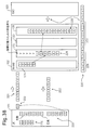
- FIG. 29 is an explanatory diagram of the rearrangement process using the rearrangement buffer 150.
- Reference numeral 200 indicates user data generated by an application program 119 operating on the mobile station 101. Each square represents each user data divided into data frames, and numerals “1” to “5” surrounded by the squares represent sequence numbers of the respective user data.
- Reference numerals 201 and 202 indicate user data transmitted from the mobile station 101 to the base station 102 and from the base station 102 to the radio network controller 103, respectively.
- the user data located above is earlier in transmission time.
- reference numeral 211 in the transmission from the mobile station 101 to the base station 102, the initial data transmission of the user data with the sequence number “2” has failed, and the sequence number “2” is the sequence number “5” due to retransmission control. Is retransmitted after the user data.
- the base station 102 transmits user data to the radio network controller 103 in the order of sequence numbers “1”, “3”, “4”, “5”, “2” as indicated by reference numeral 202. . Therefore, the first reception buffer 145 of the radio network controller 103 stores user data in the order of reception, that is, in the order of sequence numbers “1”, “3”, “4”, “5”, “2”. .
- the rearrangement processing unit 153 of the wireless network control apparatus 103 starts the processing of the sequence number “1” after the storage of the subsequent user data of the sequence numbers “2” to “5” is completed.
- the positional relationship in the vertical direction of the user data described in the first reception buffer 145, the rearrangement processing unit 153, and the rearrangement buffer 150 schematically indicates processing timings in the respective components 145, 153, and 150.
- the rearrangement processing unit 153 extracts user data from the first reception buffer 145 in the received order. For this reason, the rearrangement processing unit 153 saves subsequent user data received earlier than user data having an older sequence number in the rearrangement buffer 150 when the order of the sequence numbers does not match the reception order. .
- the rearrangement processing unit 153 saves the user data having the sequence numbers “3” to “5” to the rearrangement buffer 150.
- Reference numeral 204 indicates a state in which user data having sequence numbers “2” to “5” including user data having sequence numbers “3” to “5” is saved in the rearrangement buffer 150.
- the rearrangement processing unit 52 transmits each user data to the user data transmission unit 154 according to the sequence number order.
- the second transmission buffer 148 stores user data waiting for the transmission order. As indicated by reference numeral 205, the order of user data stored in the second transmission buffer 148 follows the order of sequence numbers.
- the rearrangement processing unit 52 performs the save process to the rearrangement buffer 150 with the user data with the sequence numbers “3” to “5”. For this reason, as indicated by reference numeral 205, the process of transmitting user data of sequence numbers “2” to “5” is delayed.
- a square indicated by reference numeral 206 means a time chart of a packet transmitted from the radio network controller 103 to the xGSN. Due to a delay in the transmission processing of user data of sequence numbers “2” to “5”, an empty time slot “e” (reference numeral 207) is present between user data of sequence numbers “1” and “2”. Many occur.
- the rearrangement processing unit 52 After retrieving the user data of sequence number “2” to the first reception buffer 145, the rearrangement processing unit 52 transmits the packets saved in the rearrangement buffer 150 to the xGSN 104 at once. For this reason, a transmission burst is generated, and a burden on the xGSN 104 is generated. This is indicated by reference numeral 208.
- the transmission burst causes data loss.
- FIG. 30 is an operation flowchart of the base station 102 shown in FIG.
- the wireless communication unit 124 receives user data transmitted from the mobile station 101 and stores the user data in the first reception buffer 125.
- the sequence data generation unit 133 acquires the sequence number embedded in the user data acquired in step S110.
- the user data transmission unit 132 transmits the user data acquired in step S110 to the radio network controller 103.
- step S113 the sequence data generation unit 133 stores the sequence number acquired in step S111 in the memory 123.
- the sequence data generation unit 133 newly stores the sequence number after the user data already stored in the memory 123.
- step S114 the sequence data generation unit 133 determines whether or not the sequence number acquired in step S111 is an expected sequence number.
- the “expected sequence number” is the sequence number with the earliest transmission order among the sequence numbers of untransmitted user data. In this embodiment, it is assumed that the transmission order is determined in ascending order. In this case, the “expected sequence number” is the smallest sequence number among the sequence numbers among the untransmitted packets.
- step S114 N
- the processor 120 returns the process to step S110.
- the sequence data generation unit 133 accumulates in the memory 13 a sequence of transmitted user data having a sequence number after the expected sequence number.
- step S115 the sequence data generating unit 133 sets the value of the index variable i to (expected sequence number + 1). ).
- steps S116 and S117 the sequence data generation unit 133 searches for the minimum expected sequence number that is not stored in the memory 123. That is, in step S116, the sequence data generation unit 133 determines whether or not a sequence number equal to the value of the index variable i is stored in the memory 123.
- step S116 the sequence data generating unit 133 increments the value of the index variable i by 1 in step S117 and steps S116 and S116. Repeat S117.
- step S118 the sequence data generating unit 133 includes consecutive sequence numbers from the expected sequence number to (i-1). Generate sequence data.
- the format of the sequence data may be the same as the format described with reference to FIG.
- the sequence data transmission unit 135 transmits the sequence data to the second packet transmission / reception device 3.
- step S119 the sequence data generation unit 133 deletes the sequence numbers from the expected sequence number stored in the memory 123 to (i-1).
- step S120 the sequence data generation unit 133 updates the value of the expected sequence number to the value of the index variable i. After that, the processor 120 returns the process to step S110.
- FIG. 31 is an explanatory diagram of a first example of the operation of the communication system 1 shown in FIG.
- Reference numeral 210 indicates user data generated by an application program 119 operating on the mobile station 101.
- Each square represents each user data divided into data frames, and numerals “1” to “5” surrounded by the squares represent sequence numbers of the respective user data.
- Reference numeral 211 indicates user data transmitted from the mobile station 101 to the base station 102. The higher the data, the earlier the transmission time.
- Reference numeral 212 indicates user data and sequence data transmitted from the base station 102 to the radio network controller 103. The sequence data is shown as a square surrounding the character “S”.
- the initial data transmission of the user data with the sequence number “2” fails, and the sequence number “2” Is retransmitted after the user data.
- the sequence numbers “1”, “3”, “4”, “5”, and “2” are transmitted to the radio network controller 103 in the order (step S112).
- the value of the expected sequence number becomes “2” due to the failure to receive the user data of sequence number 2. Therefore, the sequence numbers “3”, “4”, and “5” are stored in the memory 13 until the base station 102 acquires the user data with the sequence number 2.
- the sequence data generating unit 133 When the base station 102 receives the user data having the sequence number 2 (step S114: Y), the sequence data generating unit 133 generates the transmitted sequence data S including the sequence numbers 2 to 5 (step S118).
- the sequence data S may have sequence numbers 2 to 5 arranged in accordance with the transmission order of user data from the base station 102 to the radio network controller 103. For example, in this example, the sequence numbers 2 to 5 stored in the sequence data S are arranged in the order of “3”, “4”, “5”, “2”.
- Sequence data transmission unit 135 transmits sequence data S after the user data of sequence number “2”.
- Reference numeral 212 indicates a state in which the sequence data S is transmitted to the radio network controller 103 after the user data having the sequence number “2”.
- FIG. 32 is a flowchart of reception processing by the radio network controller 103 shown in FIG.
- the first communication unit 144 of the radio network controller 103 receives user data and / or sequence data transmitted from the base station 102.
- the first communication unit 144 stores the data received in step S130 in the first reception buffer 145 in the order received.
- the radio network controller 103 stores the data received from the base station 102 in the first reception buffer 145 by repeating steps S130 and S131.
- the rearrangement processing unit 153 shown in FIG. 28 rearranges the user data received from the base station 102 and stored in the first reception buffer 145 in the order of the sequence numbers of the respective user data, and then transfers the data to the xGSN 104.
- step S140 the rearrangement processing unit 153 determines whether there is sequence data stored in the first reception buffer 145. When there is no sequence data stored in the first reception buffer 145 (step S140: N), the rearrangement processing unit 153 moves the process to step S147 (reference symbol A). If there is sequence data stored in the first reception buffer 145 (step S140: Y), the rearrangement processing unit 153 moves the process to step S141.
- step S141 the rearrangement processing unit 153 extracts the sequence data from the first reception buffer 145.
- step S142 the rearrangement processing unit 153 determines whether or not the expected sequence number is included in the extracted sequence data.
- the “expected sequence number” means that the sequence number is the smallest among the untransmitted user data and the subsequent user data is still rearranged This is a sequence number of user data that has not been rearranged by the unit 153.
- step S142: N If the expected sequence number is not included in the sequence data (step S142: N), the rearrangement processing unit 153 proceeds to step S147 (reference symbol A). When the expected sequence number is included in the sequence data (step S142: Y), the rearrangement processing unit 153 moves the process to step S143.
- step S143 the user data receiving unit 151 extracts the user data having the expected sequence number from the first reception buffer 145.
- the user data transmission unit 154 transmits the user data extracted in step S143 to the xGSN 104.
- step S145 the rearrangement processing unit 153 updates the expected sequence number by incrementing the expected sequence number by one.
- step S146 the rearrangement processing unit 153 determines whether or not the updated expected sequence number is included in the sequence data. If the expected sequence number is included in the sequence data (step S146: Y), the rearrangement processing unit 153 returns the process to step S143.
- the processor 140 repeatedly executes steps S143 to S146.
- the processor 140 can extract user data having consecutive sequence numbers from the first reception buffer 145 according to the sequence number order, and transmit the user data to the xGSN 104. That is, by extracting the sequence data from the first reception buffer 145 according to the sequence number order, the rearrangement processing unit 153 can perform the rearrangement process without using the rearrangement buffer.
- step S146: N If the expected sequence number is not included in the sequence data (step S146: N), the processor 140 returns the process to step S140.
- step S147 the rearrangement processing unit 153 determines whether or not received user data is stored in the first reception buffer 145. If there is received user data (step S147: Y), the rearrangement processing unit 153 moves the process to step S148. If there is no received user data (step S147: N), the rearrangement processing unit 153 moves the process to step S154.
- step S148 the rearrangement processing unit 153 copies the user data extracted from the first reception buffer 145 by the user data reception unit 151 to the rearrangement buffer 150, thereby rearranging the user data in the first reception buffer 145.
- the rearrangement processing unit 153 stores the user data to be newly stored in addition to the user data already stored.
- step S149 the rearrangement processing unit 153 determines whether the sequence number of the user data saved in the rearrangement buffer 150 in step S148 is the same as the expected sequence number. If the sequence number of the saved user data is the expected sequence number (step S149: Y), the rearrangement processing unit 153 moves the process to step S150.
- step S150 the rearrangement processing unit 153 transmits, to the xGSN 104, one or more continuous user data including the user data of the expected sequence number among the user data stored in the rearrangement buffer 150.
- step S151 the rearrangement processing unit 153 updates the value of the expected sequence number to (the maximum value of the sequence number of the user data transmitted in S150 + 1).
- step S149 the rearrangement processing unit 153 moves the process to step S152.
- step S152 the rearrangement processing unit 153 determines whether the rearrangement timer is running.
- the rearrangement timer may be a software timer realized by the processing of the processor 140, for example. Time measurement by the reordering timer starts when user data having a sequence number other than the expected sequence number is saved in the empty reordering buffer 150.
- the rearrangement timer is a timer used for transmitting user data remaining in the rearrangement buffer 150 to the xGSN 104 when the user data is saved in the rearrangement buffer 150 and a predetermined time or more elapses.
- step S152 If it is determined in step S152 that the reordering timer has not been activated (step S152: N), the reordering unit 153 proceeds to step S153.
- step S153 the rearrangement processing unit 153 activates the rearrangement timer and starts time measurement using the rearrangement timer. Thereafter, the rearrangement processing unit 153 moves the process to step S154. If it is determined in step S152 that the rearrangement timer has already been started (step S152: Y), the rearrangement processing unit 153 proceeds to step S154.
- step S154 the rearrangement processing unit 153 determines whether the rearrangement timer is running. If the reordering timer is not activated (step S154: N), the processor 140 returns the process to step S140 (reference number B). When the rearrangement timer is running (step S154: Y), the rearrangement processing unit 153 moves the process to step S155.
- step S155 the rearrangement processing unit 153 determines whether the time measured by the rearrangement timer has exceeded a predetermined time, that is, whether the time measurement by the rearrangement timer has timed out.
- the rearrangement processing unit 153 moves the process to step S156.
- step S156 the rearrangement processing unit 153 transmits all user data stored in the rearrangement buffer 150 to the xGSN 104.
- step S157 the rearrangement processing unit 153 updates the value of the expected sequence number to (the maximum value of the sequence number of the user data transmitted in S156 + 1).
- step S158 the rearrangement processing unit 153 stops the rearrangement timer. After that, the processor 140 returns the process to step S140 (reference symbol B).
- step S155 when the time count by the rearrangement timer has not timed out (step S155: N), the rearrangement processing unit 153 proceeds to step S159.
- step S159 the rearrangement processing unit 153 increases the measurement value of the rearrangement timer by a predetermined time step and updates the measurement value. After that, the processor 140 returns the process to step S30 (reference number B).
- the base station 102 transmits user data in the order of sequence numbers “1”, “3”, “4”, “5”, “2”, and then includes sequence data S including sequence numbers 2-5.
- the first reception buffer 145 of the radio network controller 103 stores user data arranged in the order of reception, that is, in the order of sequence numbers “1”, “3”, “4”, “5”, “2”. Thereafter, the sequence data S is stored. Note that the sequence numbers 2 to 5 stored in the sequence data S are arranged in the order of “3”, “4”, “5”, “2”.
- FIG. 31 shows a state where, for example, even if the processing of the radio network controller 103 is congested and user data is stored in the first reception buffer 145, the processor 140 cannot immediately start processing this user data. In such a case, even if the transmission order of certain user data is later than the transmission order of subsequent user data, reception of this user data may be completed before the processing order of this user data arrives. It is done.
- the rearrangement processing unit 153 of the radio network controller 103 starts the processing of the sequence number “1” after receiving the user data and the sequence data S that follow the sequence numbers “2” to “5”. To do.
- FIG. 31 shows a state where the rearrangement buffer 150 is empty. Such a state occurs when the user data is not saved in the rearrangement buffer 150 without the process shifting to step S147 and subsequent steps shown in FIG. At this time, the sequence number of the user data extracted from the first reception buffer 145 matches the expected sequence number, and the rearrangement processing unit 153 repeats steps S140 to S146 shown in FIG. Therefore, the expected sequence number is “2” when the rearrangement processing unit 153 extracts the sequence data S from the first reception buffer 145 after the user data having the sequence number “1”.
- the rearrangement processing unit 153 uses the sequence data S (step S141 in FIG. 33) to transfer the user data having the expected sequence number “2” and the subsequent sequence numbers “3” to “5” to the first reception buffer 145. You can know that it is stored in. Therefore, in steps S143 to S146, rearrangement processing unit 153 can retrieve the user data having consecutive sequence numbers “2” to “5” from first reception buffer 145 according to the sequence number order.
- the rearrangement processing unit 153 causes the user data transmission unit 154 to transmit user data according to the order extracted from the first reception buffer 145.
- the second transmission buffer 148 stores user data waiting for the transmission order.
- the order of user data stored in the second transmission buffer 48 follows the order of sequence numbers.
- the squares indicated by reference numeral 214 indicate storage positions in the second transmission buffer 148. In the figure, the transmission order is earlier in the data stored in the upper cells.
- the squares indicated by reference numeral 215 mean time charts of user data transmitted from the radio network controller 103 to the xGSN 104. In the figure, the data stored in the square on the right side has a higher transmission order.
- the rearrangement processing unit 153 performs user data rearrangement processing without saving user data in the rearrangement buffer 150.
- the rearrangement processing unit 153 can read the user data from the first reception buffer 145 according to the sequence number order. That is, even if user data with an older sequence number is received after user data with a lower sequence number, the user data with an older sequence number can be read from the first reception buffer 145 first and transmitted.
- Reference numeral 217 in FIG. 31 indicates that the time slot “a” that can be used is compared with the time chart 206 shown in FIG. 29 as a result of reducing the delay in the transmission processing of the user data of sequence numbers “2” to “5”. Indicates an increase.
- a burst occurs when user data is transmitted to the xGSN 104.
- the rearrangement processing unit 153 alternately performs user data read processing from the first reception buffer 145 and user data transmission processing in steps S143 to S146.
- the process of alternately performing the reading and the transmission is similar to the process in the case where the rearrangement process does not occur. Therefore, the transmission interval of each user data does not greatly differ from the case in which the rearrangement process does not occur. Therefore, the rearrangement process performed in steps S143 to S146 can prevent a transmission burst that has occurred in the rearrangement process using the rearrangement buffer 150.
- Reference numeral 216 in FIG. 31 indicates that the transmission interval of user data of sequence numbers “1” to “5” is maintained and transmission bursts are prevented.
- the rearrangement processing unit 153 can determine the storage order of each user data in the first reception buffer 145 based on the sequence data. In this case, the rearrangement processing unit 153 can retrieve the user data having a desired sequence number from the first reception buffer 145 without referring to the sequence number embedded in each user data.
- the rearrangement process using the rearrangement buffer increases the processing of the processor of the radio network controller 103 in order to copy the stored user data to the rearrangement buffer after the user data is stored in the reception buffer. For this reason, there is a possibility of causing a processing delay of user data and a failure of the data transmission function due to an overload of the processor of the radio network controller 103.
- the wireless network control apparatus 103 can perform rearrangement processing when retrieving user data from the first reception buffer 145 with reference to the sequence data. Since overloading of the processor 140 due to the use of the rearrangement buffer can be prevented, the above problems such as processing delay of user data and failure of the data transmission function can be solved.
- bursts of data transmitted from the radio network controller 103 can be prevented.
- the present embodiment can solve problems such as induction of a malfunction of the communication system 100 due to communication bursts and missing user data due to shaping.
- the base station 102 may periodically transmit the sequence data in the same manner as the first packet transmitting / receiving apparatus 2 illustrated in FIG. 3 periodically transmits the transmitted packet instruction information. According to the present embodiment, since the base station 102 can create sequence data by a relatively simple process of periodically counting sequence numbers, the present embodiment can be realized without imposing a heavy load on the base station 102. .
- the radio network controller 103 includes a sequence data request signal transmitting unit. It may be.
- the sequence data request signal transmitter transmits the sequence data request signal to the base station 102 in the same manner as the transmitted packet instruction information request signal transmitter 54 requests the first packet transmitter / receiver 2 to transmit the transmitted packet instruction information. Transmission may be requested.
- the base station 102 may include a sequence data request signal receiving unit in the same manner as the first packet transmitting / receiving apparatus 2 illustrated in FIG. 3 includes the transmitted packet instruction information request signal reception 24 illustrated in FIG. 15. Then, the sequence data request signal receiving unit may receive the sequence data request signal in the same manner as the transmitted packet instruction information request signal receiving unit 24 receives the transmitted packet instruction information request signal.
- the transmitted packet instruction information generating unit 21 and the transmitted packet instruction information transmitting unit 23 of the first packet transmitting / receiving apparatus 2 create and transmit transmitted packet instruction information when a transmitted packet instruction information request signal is received. .
- the sequence data creation unit 133 and the sequence data transmission unit 135 of the base station 102 may create and transmit sequence data when receiving the sequence data request signal. According to the present embodiment, the sequence data can be transmitted according to the demand of the radio network controller 103, so that the sequence data can be generated and transmitted efficiently.
- the first packet transmitting / receiving apparatus 2 illustrated in FIG. 3 includes the missing packet detection unit 25 illustrated in FIG. 18, and the base station 102 may include a missing data detection unit that detects a missing user.
- missing data refers to user data transmitted after subsequent user data when user data is not transmitted from the base station 102 to the radio network controller 103 in the order of the sequence numbers. .
- the base station 102 satisfies the predetermined condition after the missing data is detected.
- a transmission permission / inhibition determination unit that determines whether or not When the transmission availability determination unit determines that a predetermined condition is satisfied, the sequence data creation unit 133 and the sequence data transmission unit 135 of the base station 102 may generate and transmit sequence data. According to the present embodiment, when missing data occurs, the transmitted packet instruction information can be transmitted without determining whether the missing data has been transmitted. For this reason, this embodiment can be realized without imposing a large load on the base station 102.
- FIG. 35 is a block diagram of mobile station 101 shown in FIG.
- the processor 110 shown in FIG. 24 executes the control program 111 stored in the program storage unit 112, so that the user data transmission unit 160, the ACK acquisition unit 161, the sequence number acquisition unit 162, the sequence data creation unit 163, the sequence data The function of the transmission unit 165 is realized.
- the user data transmission unit 160 performs processing for transmitting user data generated by the execution of the application program 119 to the base station 102.
- the user data transmission unit 160 inputs user data transmitted to the base station 102 to the transmission buffer 116, and the wireless communication unit 115 transmits the packet stored in the transmission buffer 116 to the base station 102.
- the ACK acquisition unit 161 acquires an acknowledge signal received from the base station 102 for each user data by the retransmission control performed by the retransmission control unit 118.
- the sequence number acquisition unit 162 acquires the sequence number of the user data from the acknowledge signal acquired by the ACK acquisition unit 162 for each user data.
- the sequence data generation unit 163 inputs the sequence number of the user data successfully transmitted by the user data transmission unit 160 from the sequence number acquisition unit 162, and generates sequence data including these sequence numbers.
- the sequence data indicates user data transmitted by the user data transmission unit 160, and corresponds to an example of transmitted packet instruction information in the other embodiments described above.
- the sequence data generation unit 163 includes a column n1 in which these numbers are arranged in the order of transmission. , N2, n3, and n4 may be sequence data.
- the sequence data generation unit 163 inputs the sequence number from the sequence number acquisition unit 162.
- the sequence data generation unit 163 stores the input sequence number in the memory 113.
- the sequence data generation unit 163 adds a sequence number sequence arranged in the order of transmission of user data by adding each sequence number to the sequence number sequence stored in the memory 113 until then. Is generated.
- the sequence data generation unit 163 reads a sequence number sequence stored in the memory 113 at a transmission timing described later, and outputs sequence data including the sequence number sequence to the sequence data transmission unit 165.
- the sequence data transmission unit 165 performs processing for transmitting the sequence data generated by the sequence data generation unit 163 to the base station 102.
- the sequence data transmission unit 165 inputs the sequence data to the transmission buffer 116, and the wireless communication unit 115 transmits the sequence data stored in the transmission buffer 116 to the base station 102.
- FIG. 36 is a second example of a block diagram of the base station 102 shown in FIG.
- the processor 120 shown in FIG. 25 executes the control program 121 stored in the program storage unit 122, so that the functions of the user data reception unit 171, the sequence data reception unit 172, the rearrangement processing unit 173, and the user data transmission unit 174 are performed. Is realized.
- the reordering buffer 130 shown in FIG. 25 receives the received user data from the first receiving buffer 125 as necessary during the reordering process of the user data received from the mobile station 101. It is a buffer used for saving.
- FIG. 37 is an operation flowchart of the mobile station 101 shown in FIG.
- the user data transmission unit 160 acquires user data generated by the execution of the application program 119.
- the user data transmission unit 160 transmits the user data acquired in step S160 to the base station 102.
- the wireless communication unit 115 receives an acknowledge signal (ACK) or a negative acknowledgment signal (NACK) from the base station 102 for the user data transmitted in step S161.
- ACK acknowledge signal
- NACK negative acknowledgment signal
- step S163 the processor 110 determines whether or not the wireless communication unit 115 has received an acknowledge signal.
- the wireless communication unit 115 receives a negative response signal (S163: N)
- the processor 110 returns the process to step S161 and retransmits the user data.
- the wireless communication unit 115 receives an acknowledge signal in the determination of step S163 (S163: Y)
- the processor 110 moves the process to step S164.
- step S164 the ACK acquisition unit 161 acquires an acknowledge signal from the reception buffer 117. Then, the sequence number acquisition unit 162 extracts the sequence number of the user data for which the acknowledge signal is returned from the acquired acknowledge signal. The sequence data generation unit 163 inputs the extracted sequence number from the sequence number acquisition unit 162.
- step S165 the sequence data generation unit 163 stores the sequence number acquired in step S164 in the memory 113.
- the user data generation unit 163 newly stores the sequence number after the user data already stored in the memory 113.
- step S166 the sequence data generation unit 163 determines whether or not the sequence number acquired in step S164 is an expected sequence number.
- the “expected sequence number” is the sequence number with the earliest transmission order among the sequence numbers of untransmitted user data. In this embodiment, it is assumed that the transmission order is determined in ascending order. In this case, the “expected sequence number” is the smallest sequence number among the sequence numbers among the untransmitted packets.
- step S164 If the sequence number acquired in step S164 is not the expected sequence number (step S166: N), the processor 110 returns the process to step S160.
- step S164 When the sequence number acquired in step S164 is the expected sequence number (step S166: Y), in step S167, the sequence data generation unit 163 sets the value of the index variable i to (expected sequence number + 1).
- step S168 the sequence data generation unit 163 searches for the minimum expected sequence number that is not stored in the memory 113. That is, in step S168, the sequence data generation unit 163 determines whether or not a sequence number equal to the value of the index variable i is stored in the memory 113. As long as a sequence number equal to the value of the index variable i is stored in the memory 113 (step S168: Y), the sequence data generation unit 163 increments the value of the index variable i by 1 in step S169, and steps S168 and Repeat S169.
- step S170 the sequence data generation unit 163 includes consecutive sequence numbers from the expected sequence number to (i-1). Generate sequence data.
- the sequence data transmission unit 165 transmits sequence data to the base station 102.
- step S171 the sequence data generation unit 163 erases the sequence numbers from the expected sequence number stored in the memory 113 to (i-1).
- step S172 the sequence data generation unit 163 updates the value of the expected sequence number to the value of the index variable i. After that, the processor 110 returns the process to step S160.
- FIG. 38 is an explanatory diagram of a second example of the operation of the communication system 1 shown in FIG.
- Reference numeral 220 indicates user data generated by the application program 119.
- Each square represents each user data divided into data frames, and numerals “1” to “5” surrounded by the squares represent sequence numbers of the respective user data.
- Reference numeral 221 indicates user data transmitted from the mobile station 101 to the base station 102, Numbers “1” to “5” surrounded by squares indicate the sequence numbers of the respective user data. The data on the right side is transmitted earlier.
- Reference numeral 222 indicates an ACK signal transmitted from the base station 102 to the mobile station 101 in response to the transmission user data indicated by the reference numeral 221.
- Numbers “1” to “5” surrounded by squares indicate the sequence numbers of user data successfully received by the base station 102. The data on the left side is earlier in transmission time.
- the initial data transmission of the user data with the sequence number “2” fails, and the sequence number “2” is retransmitted after the user data with the sequence number “5” by retransmission control.
- the sequence numbers “1”, “3”, “4”, “5”, and “2” are transmitted to the radio network controller 103 in the order (step S161).
- the value of the expected sequence number becomes “2” due to the transmission failure of the user data of sequence number 2. Therefore, the sequence numbers “3”, “4”, and “5” are stored in the memory 113 until the mobile station 101 receives an ACK signal for the user data of sequence number 2.
- Reference numeral 223 indicates how the sequence number is stored in the memory 113.
- the sequence data generation unit 163 When the mobile station 102 receives the ACK signal for the user data with the sequence number 2 (step S166: Y), the sequence data generation unit 163 generates the transmitted sequence data S including the sequence numbers 2 to 5 (step S170).
- the sequence data S may have sequence numbers 2 to 5 arranged in accordance with the transmission order of user data from the mobile station 101 to the base station 102. For example, in this example, the sequence numbers 2 to 5 stored in the sequence data S are arranged in the order of “3”, “4”, “5”, “2”.
- the sequence data transmission unit 165 transmits the sequence data S after the user data of the sequence number “2”.
- Reference numeral 223 indicates a state in which the sequence data S is transmitted to the radio network controller 103 after the user data having the sequence number “2”.
- FIG. 39 is a flowchart of the reception process by the base station 102 shown in FIG.
- the wireless communication unit 124 of the base station 102 receives user data and / or sequence data transmitted from the mobile station 101.
- the wireless communication unit 124 stores the data received in step S180 in the first reception buffer 125 in the order received.
- the base station 102 stores the data received from the mobile station 101 in the first reception buffer 125 by repeating steps S180 and S181.
- the rearrangement processing unit 173 shown in FIG. 36 rearranges the user data received from the mobile station 101 and stored in the first reception buffer 125 in the order of the sequence number of each user data, and then the radio network controller 103. Forward to.
- step S190 the rearrangement processing unit 173 determines whether there is sequence data stored in the first reception buffer 125. When there is no sequence data stored in the first reception buffer 125 (step S190: N), the rearrangement processing unit 173 moves the process to step S197 (reference numeral A). If there is sequence data stored in the first reception buffer 125 (step S190: Y), the rearrangement processing unit 173 moves the process to step S191.
- step S191 the rearrangement processing unit 173 extracts the sequence data from the first reception buffer 125.
- step S192 the rearrangement processing unit 173 determines whether or not the expected sequence number is included in the extracted sequence data.
- the “expected sequence number” means that the sequence number is the smallest among the untransmitted user data, and the subsequent user data is still the rearrangement processing unit 173. This is a sequence number of user data that has not been subjected to the rearrangement process.
- step S192: N When the expected sequence number is not included in the sequence data (step S192: N), the rearrangement processing unit 173 moves the process to step S197 (reference number A). When the expected sequence number is included in the sequence data (step S192: Y), the rearrangement processing unit 173 moves the process to step S193.
- step S193 the user data receiving unit 171 extracts the user data having the expected sequence number from the first reception buffer 125.
- the user data transmission unit 174 transmits the user data extracted in step S193 to the radio network controller 103.
- step S195 the rearrangement processing unit 173 updates the expected sequence number by incrementing the expected sequence number by one.
- step S196 the rearrangement processing unit 173 determines whether or not the updated expected sequence number is included in the sequence data.
- the rearrangement processing unit 173 returns the process to step S193.
- the processor 120 repeatedly executes steps S193 to S196.
- the processor 120 can extract user data having consecutive sequence numbers from the first reception buffer 125 according to the sequence number order, and transmit the user data to the radio network controller 103. That is, by extracting the sequence data from the first reception buffer 125 according to the sequence number sequence, the rearrangement processing unit 173 can perform the rearrangement process without using the rearrangement buffer.
- step S196: N the processor 120 returns the process to step S190.
- step S197 the rearrangement processing unit 173 determines whether or not received user data is stored in the first reception buffer 125. If there is received user data (step S197: Y), the rearrangement processing unit 173 moves the process to step S198. When there is no received user data (step S197: N), the rearrangement processing unit 173 moves the process to step S204.
- step S198 the rearrangement processing unit 173 copies the user data extracted from the first reception buffer 125 by the user data reception unit 171 to the rearrangement buffer 130, thereby sorting the user data in the first reception buffer 125 into the rearrangement buffer.
- the rearrangement processing unit 173 stores the user data to be newly stored in addition to the user data already stored.
- step S199 the rearrangement processing unit 173 determines whether or not the sequence number of the user data saved in the rearrangement buffer 130 in step S198 is the same as the expected sequence number. If the sequence number of the saved user data is the expected sequence number (step S199: Y), the rearrangement processing unit 173 moves the process to step S200.
- step S ⁇ b> 200 the rearrangement processing unit 173 transmits one or more continuous user data including the user data of the expected sequence number among the user data stored in the rearrangement buffer 130 to the radio network controller 103.
- step S201 the rearrangement processing unit 173 updates the value of the expected sequence number to (the maximum value of the sequence number of the user data transmitted in S200 + 1).
- step S199 the rearrangement processing unit 173 moves the process to step S202.
- step S202 the rearrangement processing unit 173 determines whether the rearrangement timer is running.
- the rearrangement timer may be a software timer realized by the processing of the processor 120, for example. Time measurement by the reordering timer starts when user data having a sequence number other than the expected sequence number is saved in the empty reordering buffer 130.
- the rearrangement timer is a timer used to transmit user data remaining in the rearrangement buffer 130 to the radio network controller 103 when the user data is saved in the rearrangement buffer 130 and a predetermined time or more has elapsed. is there.
- step S202 If it is determined in step S202 that the reordering timer is not activated (step S202: N), the reordering unit 173 moves the process to step S203.
- step S203 the rearrangement processing unit 173 activates the rearrangement timer and starts time measurement using the rearrangement timer. Thereafter, the rearrangement processing unit 173 moves the process to step S204. If it is determined in step S202 that the rearrangement timer has already been started (step S202: Y), the rearrangement processing unit 173 proceeds to step S204.
- step S204 the rearrangement processing unit 173 determines whether the rearrangement timer is running. When the reordering timer is not activated (step S204: N), the processor 120 returns the process to step S190 (reference number B). When the rearrangement timer is activated (step S204: Y), the rearrangement processing unit 173 proceeds to step S205.
- step S205 the reordering unit 173 determines whether the time measured by the reordering timer has exceeded a predetermined time, that is, whether the time measured by the reordering timer has timed out.
- the rearrangement processing unit 173 moves the process to step S206.
- step S206 the rearrangement processing unit 173 transmits all user data stored in the rearrangement buffer 130 to the radio network controller 103.
- step S207 the rearrangement processing unit 173 updates the value of the expected sequence number to (maximum value of sequence number of user data transmitted in S206 + 1).
- step S208 the rearrangement processing unit 173 stops the rearrangement timer. After that, the processor 120 returns the process to step S190 (reference number B).
- step S205 when the time measured by the reordering timer has not timed out (step S205: N), the reordering unit 173 moves the process to step S209.
- step S209 the rearrangement processing unit 173 increases the measurement value of the rearrangement timer by a predetermined time step, and updates the measurement value. After that, the processor 120 returns the process to step S190 (reference number B).
- the mobile station 101 transmits user data in the order of sequence numbers “1”, “3”, “4”, “5”, “2”, and then sequence data S including sequence numbers 2-5.
- the first reception buffer 135 of the base station 102 stores user data arranged in the order of reception, that is, in the order of sequence numbers “1”, “3”, “4”, “5”, “2”. Is stored with sequence data S. Note that the sequence numbers 2 to 5 stored in the sequence data S are arranged in the order of “3”, “4”, “5”, “2”.
- FIG. 38 shows a state where, for example, even if the processing of the base station 102 is congested and user data is stored in the first reception buffer 125, the processor 120 cannot immediately start processing this user data. In such a case, even if the transmission order of certain user data is later than the transmission order of subsequent user data, reception of this user data may be completed before the processing order of this user data arrives. It is done. For example, in FIG. 38, the rearrangement processing unit 173 of the base station 102 starts the processing of the sequence number “1” after receiving the subsequent user data and sequence data S of the sequence numbers “2” to “5”.
- FIG. 38 shows a state where the rearrangement buffer 130 is empty. Such a state occurs when the user data is not saved in the rearrangement buffer 130 without the processing shifting to step S197 and subsequent steps shown in FIG. At this time, the sequence number of the user data extracted from the first reception buffer 125 matches the expected sequence number, and the rearrangement processing unit 173 repeats steps S190 to S196 shown in FIG. Therefore, after the rearrangement processing unit 173 extracts the user data having the sequence number “1” from the reception buffer 125, the expected sequence number is “2”.
- the rearrangement processing unit 173 uses the sequence data S (step S191 in FIG. 40) to transfer the user data having the expected sequence number “2” and the subsequent sequence numbers “3” to “5” to the first reception buffer 125. You can know that it is stored in. For this reason, in steps S193 to S196, the rearrangement processing unit 173 can retrieve the user data having the consecutive sequence numbers “2” to “5” from the first reception buffer 125 in the order of the sequence numbers.
- the rearrangement processing unit 173 causes the user data transmission unit 174 to transmit user data according to the order extracted from the first reception buffer 125.
- the second transmission buffer 128 stores user data waiting for the transmission order.
- the order of the user data stored in the second transmission buffer 48 follows the order of the sequence numbers.
- the square indicated by reference numeral 225 indicates the storage position in the second transmission buffer 128.
- the transmission order is earlier in the data stored in the upper cells.
- the squares indicated by reference numeral 226 mean a time chart of user data transmitted from the base station 102 to the radio network controller 103. In the figure, the data stored in the square on the right side has a higher transmission order.
- the rearrangement processing unit 173 performs user data rearrangement processing without saving user data in the rearrangement buffer 130.
- the rearrangement processing unit 173 can read the user data from the first reception buffer 125 according to the sequence number order. That is, even when user data with an older sequence number is received after user data with a lower sequence number, the user data with an older sequence number can be read from the first reception buffer 125 first and transmitted.
- Reference numeral 228 in FIG. 38 indicates that the available time slot “a” has increased as a result of the delay in the transmission processing of the user data of sequence numbers “2” to “5” being reduced.
- the rearrangement processing unit 173 alternately performs user data read processing from the first reception buffer 125 and user data transmission processing in steps S193 to S196. Since the process of alternately performing the reading and the transmission is similar to the process when the rearrangement process is not generated, the transmission interval of each user data is not greatly different from that when the rearrangement process is not generated. Therefore, the rearrangement process performed in steps S193 to S196 can prevent a transmission burst that has occurred in the rearrangement process using the rearrangement buffer.
- Reference numeral 227 in FIG. 38 indicates a state in which the transmission interval of user data of sequence numbers “1” to “5” is maintained and transmission bursts are prevented.
- the rearrangement processing unit 173 can determine the storage order of each user data in the first reception buffer 125 based on the sequence data. In this case, the rearrangement processing unit 173 can retrieve user data having a desired sequence number from the first reception buffer 125 without referring to the sequence number embedded in each user data.
- the rearrangement process using the rearrangement buffer increases the processing of the processor of the base station 102 in order to copy the stored user data to the rearrangement buffer after the user data is stored in the reception buffer. For this reason, there is a possibility that the processing delay of the user data or the failure of the data transmission function due to the overload of the processor of the base station 102 may occur.
- the base station 102 when the processing of the base station 102 is delayed and a large amount of user data is accumulated in the first reception buffer 125, the sequence data is also included in the first data together with the user data. Accumulated in the reception buffer 125. Therefore, the base station 102 can perform the rearrangement process when retrieving the user data from the first reception buffer 125 with reference to the sequence data. Since overloading of the processor 120 due to the use of the rearrangement buffer can be prevented, the above problems such as processing delay of user data and failure of the data transmission function can be solved.
- bursts of data transmitted from the base station 125 can be prevented.
- the present embodiment can solve problems such as induction of a malfunction of the communication system 100 due to communication bursts and missing user data due to shaping.
- the mobile station 101 may periodically transmit sequence data in the same manner as the first packet transmitting / receiving apparatus 2 illustrated in FIG. 3 periodically transmits the transmitted packet instruction information. According to this embodiment, since the mobile station 101 can create sequence data by a relatively simple process of periodically counting sequence numbers, this embodiment can be realized without imposing a heavy load on the mobile station 101. .
- the base station 102 includes a sequence data request signal transmitting unit. Also good.
- the sequence data request signal transmitter transmits the sequence data request to the mobile station 101 in the same manner as the transmitted packet instruction information request signal transmitter 54 requests the first packet transmitter / receiver 2 to transmit the transmitted packet instruction information. Transmission may be requested.
- the mobile station 101 may include a sequence data request signal receiving unit in the same manner as the first packet transmitting / receiving apparatus 2 illustrated in FIG. 3 includes the transmitted packet instruction information request signal reception 24 illustrated in FIG. 15. Then, the sequence data request signal receiving unit may receive the sequence data request signal in the same manner as the transmitted packet instruction information request signal receiving unit 24 receives the transmitted packet instruction information request signal.
- the transmitted packet instruction information generating unit 21 and the transmitted packet instruction information transmitting unit 23 of the first packet transmitting / receiving apparatus 2 create and transmit transmitted packet instruction information when a transmitted packet instruction information request signal is received. .
- the sequence data creation unit 163 and the sequence data transmission unit 165 of the mobile station 101 may create and transmit sequence data when receiving a sequence data request signal. According to the present embodiment, sequence data can be transmitted according to the demand of the base station 102, so that sequence data can be efficiently generated and transmitted.
- the mobile station 101 may include a missing data detection unit that detects a missing user in the same manner as the first packet transmission / reception device 2 illustrated in FIG. 3 includes the missing packet detection unit 25 illustrated in FIG.
- missing data refers to user data transmitted after the subsequent user data when the user data is not transmitted from the mobile station 101 to the base station 102 in the order of the sequence numbers.
- the mobile station 101 satisfies the predetermined condition after the missing data is detected.
- a transmission permission / inhibition determination unit that determines whether or not When the transmission availability determination unit determines that a predetermined condition is satisfied, the sequence data creation unit 163 and the sequence data transmission unit 165 of the mobile station 101 may generate and transmit sequence data. According to the present embodiment, when missing data occurs, the transmitted packet instruction information can be transmitted without determining whether the missing data has been transmitted. For this reason, the present embodiment can be realized without imposing a large load on the mobile station 101.
Abstract
A packet transmitter (2) is provided with a packet transmission means (20) which transmits a packet having a sequence number fixed thereto to a transmission destination device (3); a transmitted packet indicating information generation means (21) which generates transmitted packet indicating information indicating a packet transmitted by the packet transmission means (20); and a transmitted packet indicating information transmission means (23) which transmits the transmitted packet indicating information to the transmission destination device (3) separately from the packet.
Description
本発明は、シーケンス番号が定められたパケットを送受信する通信システムに関し、受信側装置に受信されたパケットの並べ替え処理を含んでもよい。
The present invention relates to a communication system that transmits and receives packets with sequence numbers, and may include rearrangement processing of packets received by a receiving-side device.
近年、W-CDMA(Wideband-Code Division Multiple Access)における上り回線のパケット通信を高速化する伝送規格として、HSUPA (High Speed Uplink Packet Access)が検討されている。
Recently, HSUPA (High Speed Uplink Packet Access) has been studied as a transmission standard for speeding up uplink packet communication in W-CDMA (Wideband-Code Division Multiple Access).
図1は、HSUPAにおける各部のレイヤ構成図である。移動局(UE)は、レイヤL1の物理レイヤ(PHY)と、レイヤL2のMACサブレイヤ(MAC-d、MAC-es/MAC-e)及びRLC(Radio Link. Control)レイヤと、を備えている。MACサブレイヤは、MAC-d(MAC dedicated)レイヤと、MAC-e(MAC-enhanced) レイヤと、MAC-esレイヤ(MAC-enhanced sub layer)を備えている。
FIG. 1 is a layer configuration diagram of each part in HSUPA. The mobile station (UE) includes a layer L1 physical layer (PHY), a layer L2 MAC sublayer (MAC-d, MAC-es / MAC-e), and an RLC (Radio Link. Control) layer. . The MAC sublayer includes a MAC-d (MAC-dedicated) layer, a MAC-e (MAC-enhanced) -layer, and a MAC-es layer (MAC-enhanced-sub-layer).
基地局(Node B)は、Uuインタフェースに従って移動局と通信するための物理レイヤ(PHY)、Iub/Iurインタフェースに従って無線網制御装置(RNC)とパケット通信するためのTNLレイヤ(Transport Network Layer)を備える。基地局は、更にMAC-eレイヤ、EDCH FP(Enhanced DCH Frame Protocol)レイヤを備えている。ここに、Uu(The Radio interface between UTLAN and the User Equipment)インタフェースとは、無線アクセスネットワークと移動局との間のインタフェースである。また、Iub(Interface between an RNC and a Node B)インタフェースとは、基地局と無線網制御装置との間のインタフェースである。またIur(A logical interface between two RNC)インタフェースとは、2つの無線網制御装置同士のインタフェースである。
The base station (Node B) has a physical layer (PHY) for communicating with the mobile station according to the Uu interface, and a TNL layer (Transport Network 通信 Layer) for packet communication with the radio network controller (RNC) according to the Iub / Iur interface. Prepare. The base station further includes a MAC-e layer and an EDCH FP (Enhanced DCH Frame Protocol) layer. Here, the Uu (The Radio interface interface between the Bluetooth, the UTLAN, and the User Equipment) is an interface between the radio access network and the mobile station. The Iub (Interface (between an RNC and a Node B) interface is an interface between the base station and the radio network controller. The Iur (A | logical | interface | between | two | RNC) interface is an interface between two radio network controllers.
無線網制御装置であるSRNC(Serving RNC)はTNLレイヤ、EDCH FPレイヤ、MAC-esレイヤ、MAC-dレイヤ、RLCレイヤを備えている。また、無線網制御装置であるDRNC(Drift RNC)は、TNLレイヤを備えている。
SRNC (Serving RNC), which is a radio network controller, includes a TNL layer, an EDCH FP layer, a MAC-es layer, a MAC-d layer, and an RLC layer. Also, DRNC (Drift RNC), which is a radio network controller, includes a TNL layer.
図2は、移動局、基地局、無線網制御装置間で送受されるデータフレームを示す図である。移動局は、ネットワークへと送信するデータフレームを短いRLC PDU(MAC-d PDU)へ分割する。移動局は、複数のMAC-d PDUを多重化してMAC-es PDUを生成する。このMAC-es PDUは、送信されるデータフレーム中における各PDUの順序を示すシーケンス番号であるTSNを含んでいる。移動局は、さらに複数のMAC-es PDUを多重化してEDCH FP(Frame Protocol for Enhanced Dedicated Channel)フレームを作成する。
FIG. 2 is a diagram showing data frames transmitted / received between a mobile station, a base station, and a radio network controller. The mobile station divides a data frame to be transmitted to the network into short RLC PDUs (MAC-d PDU). The mobile station generates a MAC-esMACPDU by multiplexing a plurality of MAC-d PDUs. This MAC-es PDU includes a TSN that is a sequence number indicating the order of each PDU in the transmitted data frame. The mobile station further multiplexes a plurality of MAC-es PDUs to create an EDCH FP (Frame Protocol for Enhanced Dedicated Channel) frame.
HSUPA方式は、データ伝送速度の向上のために、複数の通信チャネル上においてHARQ(Hybrid Automatic Repeat Request)制御を行っている。この結果、どの通信チャネルを経由したデータが先に基地局に受信されるかが不定であり、基地局で受信されるデータの順序は保証されない。
The HSUPA system performs HARQ (Hybrid Automatic Repeat Request) control on a plurality of communication channels in order to improve the data transmission rate. As a result, it is uncertain which communication channel is used to receive data via the base station first, and the order of data received by the base station is not guaranteed.
このため基地局は、各MAC-es PDUにシーケンス番号TSNを付与し、無線網制御装置(S-RNC)が、シーケンス番号TSNに基づいてMAC-es PDUの並べ替え処理を行っている。無線網制御装置(S-RNC)は、受信したEDCH FPフレームからMac-es PDUを取り出し、各Mac-es PDUをTSNに従って並べ替えを行った上で、データフレームの再生を行う。
For this reason, the base station assigns a sequence number TSN to each MAC-es PDU, and the radio network controller (S-RNC) performs a reordering process of the MAC-es PDU based on the sequence number TSN. The radio network controller (S-RNC) takes out the Mac-es PDU from the received EDCH FP frame, rearranges each Mac-es PDU according to the TSN, and reproduces the data frame.
無線網制御装置における、従来のMac-es PDUの並べ替え処理は、例えば以下の通りである。無線網制御装置は、受信した順序でMac-es PDUを受信バッファから取り出す。Uuインタフェース上でデータの欠落が生じた場合には、無線網制御装置に受信されるデータにおいて、シーケンス番号の欠落が生じる。無線網制御装置は、受信バッファから取り出したデータのシーケンス番号の欠落を検出したとき、欠落したデータに続く後続データを並べ替え処理用バッファに一時移し替える。その後、欠落したデータが受信バッファから取り出されたとき、無線網制御装置は、並べ替え処理用バッファに蓄えていた後続データとともに、欠落したデータを、シーケンス番号の順序に従う順序でネットワークへ送信する。
For example, the conventional Mac-es® PDU rearrangement process in the radio network controller is as follows. The radio network controller extracts the Mac-es PDU from the reception buffer in the order of reception. When data is lost on the Uu interface, sequence numbers are lost in the data received by the radio network controller. When the wireless network control device detects a missing sequence number of the data extracted from the reception buffer, the wireless network control device temporarily transfers subsequent data following the missing data to the rearrangement processing buffer. Thereafter, when the missing data is taken out from the reception buffer, the radio network controller transmits the missing data together with the subsequent data stored in the rearrangement processing buffer to the network in the order according to the order of the sequence numbers.
上述の従来の並べ替え処理では、無線網制御装置は、受信バッファから取り出したデータを、並べ替え処理用バッファに移し替える処理が必要になる。このため並べ替え処理が多発する状況下では、並べ替え処理用バッファにデータを移し替える処理のために、無線網制御装置を制御する処理装置の負荷が増加し、処理遅延を招くという問題があった。
In the above-described conventional rearrangement process, the radio network controller needs to transfer the data extracted from the reception buffer to the rearrangement process buffer. For this reason, in a situation where rearrangement processing occurs frequently, there is a problem in that the load on the processing device that controls the radio network controller increases due to the processing of transferring data to the rearrangement processing buffer, resulting in processing delay. It was.
上記事情に鑑み、開示のパケット送信装置、パケット受信装置、通信システム及びパケット通信方法は、シーケンス番号が定められたパケットを受信する受信装置において、シーケンス番号に従ったパケットの並べ替え処理の効率を向上することを目的とする。
In view of the above circumstances, the disclosed packet transmission device, packet reception device, communication system, and packet communication method have improved the efficiency of packet rearrangement processing according to a sequence number in a reception device that receives a packet with a specified sequence number. It aims to improve.
ある実施例の形態によるパケット送信装置は、シーケンス番号が定められたパケットを送信先装置へ送信するパケット送信手段と、パケット送信手段により送信された送信済みパケットを指示する送信済みパケット指示情報を生成する送信済みパケット指示情報生成手段と、パケットと別に、送信済みパケット指示情報を送信先装置へ送信する送信済みパケット指示情報送信手段と、を備える。
A packet transmission apparatus according to an embodiment generates packet transmission means for transmitting a packet having a sequence number to a transmission destination apparatus, and transmitted packet instruction information for indicating a transmitted packet transmitted by the packet transmission means. And a transmitted packet instruction information transmitting means for transmitting the transmitted packet instruction information to the transmission destination device separately from the packet.
ある実施例の形態によるパケット受信装置は、シーケンス番号が定められたパケットを送信元装置から受信するパケット受信手段と、パケットを格納する受信バッファと、送信元装置により送信された送信済みパケットを指示する送信済みパケット指示情報を、パケットと別に、送信元装置から受信する送信済みパケット指示情報受信手段と、送信済みパケット指示情報により指示されたパケットを受信バッファから取り出し、かつシーケンス番号の順序でパケットを並べ替えるパケット並べ替え手段と、を備える。
A packet receiving apparatus according to an embodiment includes a packet receiving means for receiving a packet with a sequence number from a transmission source apparatus, a reception buffer for storing the packet, and a transmitted packet transmitted by the transmission source apparatus. Transmitted packet instruction information receiving means for receiving the transmitted packet instruction information to be received from the transmission source device, and the packet indicated by the transmitted packet instruction information from the reception buffer, and receiving the packet in the sequence number order. Packet rearranging means for rearranging the packets.
送信元装置が、パケットの他に送信済みパケット指示情報も受信側装置へ送信することで、受信側装置が、パケットを受信バッファから取り出す前に、パケットの並べ替えに必要なパケットが揃っているか否かを判定することが可能となる。並べ替え処理用バッファにデータを移し替えることなく、パケットの並べ替え処理を行うことができるため、パケットの並べ替える受信側装置の負荷が低減される。
Whether the packet that is necessary for the packet rearrangement is prepared before the receiving side device extracts the packet from the receiving buffer by transmitting the transmitted packet instruction information in addition to the packet to the receiving side device. It becomes possible to determine whether or not. Since the packet rearrangement process can be performed without transferring the data to the rearrangement processing buffer, the load on the receiving side apparatus that rearranges the packets is reduced.
1、100 通信システム
2 第1パケット送受信装置
3 第2パケット送受信装置
4 第3パケット送受信装置
101 移動局(UE)
102 基地局(NodeB)
103 無線網制御装置(RNC)
104 xGSN DESCRIPTION OF SYMBOLS 1,100Communication system 2 1st packet transmission / reception apparatus 3 2nd packet transmission / reception apparatus 4 3rd packet transmission / reception apparatus 101 Mobile station (UE)
102 Base station (NodeB)
103 Radio network controller (RNC)
104 xGSN
2 第1パケット送受信装置
3 第2パケット送受信装置
4 第3パケット送受信装置
101 移動局(UE)
102 基地局(NodeB)
103 無線網制御装置(RNC)
104 xGSN DESCRIPTION OF SYMBOLS 1,100
102 Base station (NodeB)
103 Radio network controller (RNC)
104 xGSN
以下、添付する図面を参照して実施例を説明する。図3は、開示の通信システムの第1例の構成図である。通信システム1は、第1パケット送受信装置2と、第2パケット送受信装置3と、第3パケット送受信装置4を備える。第1及び2パケット送受信装置2及び3は、以下に示す他の実施例のように基地局及び無線網制御装置であってよい。また、第1及び2パケット送受信装置2及び3は、以下に示す他の実施例のように移動局及び基地局であってよい。すなわち第1及び2パケット送受信装置2及び3は下位装置及び上位装置という関係にあってよい。第1及び2パケット送受信装置2及び3は、基地局同士又は無線網制御装置同士であってもよい。すなわち、第1及び2パケット送受信装置2及び3は、下位装置及び上位装置という関係でなくともよい。
Hereinafter, embodiments will be described with reference to the accompanying drawings. FIG. 3 is a configuration diagram of a first example of the disclosed communication system. The communication system 1 includes a first packet transmitter / receiver 2, a second packet transmitter / receiver 3, and a third packet transmitter / receiver 4. The first and second packet transmitting / receiving apparatuses 2 and 3 may be a base station and a radio network controller as in other embodiments described below. Further, the first and second packet transmitting / receiving apparatuses 2 and 3 may be a mobile station and a base station as in other embodiments described below. That is, the first and second packet transmitting / receiving apparatuses 2 and 3 may be in a relationship of a lower apparatus and an upper apparatus. The first and second packet transmitting / receiving apparatuses 2 and 3 may be base stations or radio network controllers. That is, the first and second packet transmission / reception devices 2 and 3 do not have to be related to the lower device and the higher device.
図4は、図3に示す第1パケット送受信装置2のハードウエア構成図の第1例である。第1パケット送受信装置2は、プロセッサ10と、制御プログラム11を記憶するプログラム記憶部12と、メモリ13と、パケット取得部14と、通信部15と、送信バッファ16と、受信バッファ17を備える。
FIG. 4 is a first example of a hardware configuration diagram of the first packet transmitting / receiving apparatus 2 shown in FIG. The first packet transmitting / receiving apparatus 2 includes a processor 10, a program storage unit 12 that stores a control program 11, a memory 13, a packet acquisition unit 14, a communication unit 15, a transmission buffer 16, and a reception buffer 17.
プロセッサ10は、CPU等のデータプロセッサにより実現され、プログラム記憶部12に格納された制御プログラム11を実行することにより、第1パケット送受信装置2の動作を制御する。プログラム記憶部12は、プロセッサ10により実行されることによりユーザデータを生成するアプリケーションプログラムを格納していてもよい。メモリ13は、制御プログラム11やアプリケーションプログラムの実行に必要なデータを記憶し、またこれらプログラムの実行の際に生成される一時的なデータを記憶する。
The processor 10 is realized by a data processor such as a CPU, and controls the operation of the first packet transmitting / receiving apparatus 2 by executing a control program 11 stored in the program storage unit 12. The program storage unit 12 may store an application program that generates user data by being executed by the processor 10. The memory 13 stores data necessary for execution of the control program 11 and application programs, and also stores temporary data generated when these programs are executed.
パケット取得部14は、第1パケット送受信装置2から第2パケット送受信装置3へ送信されるパケットを取得する。パケット取得部14が取得する各パケットには、パケットの順序を示すシーケンス番号が定められている。シーケンス番号は、各パケット内に埋め込まれていてよい。パケット取得部14は、例えば、他の通信装置からパケットを受信することによりパケットを取得してよい。また、パケット取得部14は、例えば、プロセッサ10により実行されたアプリケーションプログラムにより生成されたユーザデータを、分割したパケットを取得するソフトウエアモジュールであってもよい。
The packet acquisition unit 14 acquires a packet transmitted from the first packet transmission / reception device 2 to the second packet transmission / reception device 3. Each packet acquired by the packet acquisition unit 14 has a sequence number indicating the order of the packets. The sequence number may be embedded in each packet. For example, the packet acquisition unit 14 may acquire a packet by receiving a packet from another communication device. Further, the packet acquisition unit 14 may be a software module that acquires a packet obtained by dividing user data generated by an application program executed by the processor 10, for example.
通信部15は、第2パケット送受信装置3との間のデータの送受信を行う。例えば、通信部15は、パケット取得部14が取得したパケットを第2パケット送受信装置3へ送信する。送信バッファ16は、第2パケット送受信装置3へ送信されるデータを通信部15が受け付けるまでの間一時的に保持する。受信バッファ17は、通信部15が第2パケット送受信装置3から受信したデータを一時的に保持する。
The communication unit 15 transmits / receives data to / from the second packet transmitting / receiving device 3. For example, the communication unit 15 transmits the packet acquired by the packet acquisition unit 14 to the second packet transmitting / receiving apparatus 3. The transmission buffer 16 temporarily holds data transmitted to the second packet transmitting / receiving apparatus 3 until the communication unit 15 accepts the data. The reception buffer 17 temporarily holds data received from the second packet transmitting / receiving device 3 by the communication unit 15.
図5は、図4に示す第1パケット送受信装置2のブロック図の第1例である。プロセッサ10が、プログラム記憶部12に格納された制御プログラム11を実行することによって、パケット送信部20、送信済みパケット指示情報生成部21及び送信済みパケット指示情報送信部23の機能が実現される。
FIG. 5 is a first example of a block diagram of the first packet transmitting / receiving apparatus 2 shown in FIG. When the processor 10 executes the control program 11 stored in the program storage unit 12, the functions of the packet transmission unit 20, the transmitted packet instruction information generation unit 21, and the transmitted packet instruction information transmission unit 23 are realized.
パケット送信部20は、パケット取得部14が取得したパケットを、第2パケット送受信装置3へ送信する処理を行う。パケット送信部20は、第2パケット送受信装置3へ送信されるパケットを送信バッファ16へ入力し、通信部15は、送信バッファ16へ格納されたパケットを第2パケット送受信装置3へ送信する。
The packet transmission unit 20 performs a process of transmitting the packet acquired by the packet acquisition unit 14 to the second packet transmitting / receiving apparatus 3. The packet transmission unit 20 inputs a packet to be transmitted to the second packet transmission / reception device 3 to the transmission buffer 16, and the communication unit 15 transmits the packet stored in the transmission buffer 16 to the second packet transmission / reception device 3.
送信済みパケット指示情報生成部21は、パケット取得部14が取得したパケットを入力する。送信済みパケット指示情報生成部21は、パケット取得部14から受信したパケットがパケット送信部20により送信されたものであると見なし、パケット送信部20により送信されたパケットを指示する送信済みパケット指示情報を生成する。送信済みパケット指示情報は、パケット送信部20により送信されたパケットを、送信されたパケットをシーケンス番号によって特定してよい。
The transmitted packet instruction information generation unit 21 inputs the packet acquired by the packet acquisition unit 14. The transmitted packet instruction information generation unit 21 considers that the packet received from the packet acquisition unit 14 has been transmitted by the packet transmission unit 20, and has transmitted the packet instruction information indicating the packet transmitted by the packet transmission unit 20. Is generated. The transmitted packet instruction information may identify the packet transmitted by the packet transmission unit 20 by the sequence number of the transmitted packet.
例えば、シーケンス番号が昇順により送信順序を定めており、連続するシーケンス番号n、(n+1)、(n+2)…(n+x)をそれぞれ有する一連のパケットを指定する場合を考える。この場合、一連のパケットのシーケンス番号を、各パケットの送信順に並べた一連のシーケンス番号n、(n+1)、(n+2)…(n+x)を送信済みパケット指示情報としてよい。また、一連のパケットのシーケンス番号の範囲を示す情報(n:(n+x))を送信済みパケット指示情報としてよい。
For example, consider a case where the transmission order is determined in ascending order of sequence numbers, and a series of packets having consecutive sequence numbers n, (n + 1), (n + 2)... (N + x) are designated. In this case, a series of sequence numbers n, (n + 1), (n + 2),... (N + x) in which sequence numbers of a series of packets are arranged in the order of transmission of each packet may be used as transmitted packet instruction information. Further, information (n: (n + x)) indicating a range of sequence numbers of a series of packets may be used as transmitted packet instruction information.
本明細書における説明で使用される送信済みパケット指示情報は、パケット送信部20により送信された各パケットのシーケンス番号を、各パケットの送信順に並べた一連のシーケンス番号を含む、一組のシーケンス番号である。送信済みパケット指示情報生成部21は、パケット取得部14から取得した各パケットから、それぞれのパケットに埋め込まれていたシーケンス番号を取り出す。送信済みパケット指示情報生成部21は、取り出したシーケンス番号をメモリ13に記憶する。
The transmitted packet instruction information used in the description in the present specification includes a set of sequence numbers including a series of sequence numbers in which the sequence numbers of the packets transmitted by the packet transmitter 20 are arranged in the order of transmission of the packets. It is. The transmitted packet instruction information generation unit 21 extracts the sequence number embedded in each packet from each packet acquired from the packet acquisition unit 14. The transmitted packet instruction information generation unit 21 stores the extracted sequence number in the memory 13.
送信済みパケット指示情報生成部21は、各パケットのシーケンス番号を取り出す都度、それまでにメモリ13に記憶されているシーケンス番号の列に追加していくことにより、パケットの送信順に並べた一連のシーケンス番号の列を生成する。送信済みパケット指示情報生成部21は、後述する送信タイミングにおいて、メモリ13に記憶されているシーケンス番号の列を読み出して、シーケンス番号の列を含む送信済みパケット指示情報を送信済みパケット指示情報送信部23へ出力する。
The transmitted packet instruction information generation unit 21 adds a sequence number of each packet to the sequence number sequence stored in the memory 13 each time the sequence number is extracted. Generate a sequence of numbers. The transmitted packet instruction information generation unit 21 reads a sequence number sequence stored in the memory 13 at a transmission timing described later, and transmits transmitted packet instruction information including the sequence number sequence to a transmitted packet instruction information transmission unit. To 23.
送信済みパケット指示情報送信部23は、送信済みパケット指示情報生成部21から受信した送信済みパケット指示情報を第2パケット送受信装置3へ送信する処理を行う。送信済みパケット指示情報送信部23は、送信済みパケット指示情報を送信バッファ16へ入力し、通信部15は、送信バッファ16へ格納された送信済みパケット指示情報を第2パケット送受信装置3へ送信する。
The transmitted packet instruction information transmitting unit 23 performs a process of transmitting the transmitted packet instruction information received from the transmitted packet instruction information generating unit 21 to the second packet transmitting / receiving apparatus 3. The transmitted packet instruction information transmitting unit 23 inputs the transmitted packet instruction information to the transmission buffer 16, and the communication unit 15 transmits the transmitted packet instruction information stored in the transmission buffer 16 to the second packet transmitting / receiving apparatus 3. .
図6は、図3に示す第2パケット送受信装置3のハードウエア構成図である。第2パケット送受信装置3は、プロセッサ30と、制御プログラム31を記憶するプログラム記憶部32と、メモリ33と、第1通信部34と、第1受信バッファ35と、第1送信バッファ36を備える。また、第2パケット送受信装置3は、第2通信部37と、第2送信バッファ38と、第2受信バッファ39と、並べ替えバッファ40を備える。
FIG. 6 is a hardware configuration diagram of the second packet transmitting / receiving apparatus 3 shown in FIG. The second packet transmitting / receiving apparatus 3 includes a processor 30, a program storage unit 32 that stores a control program 31, a memory 33, a first communication unit 34, a first reception buffer 35, and a first transmission buffer 36. The second packet transmitting / receiving apparatus 3 includes a second communication unit 37, a second transmission buffer 38, a second reception buffer 39, and a rearrangement buffer 40.
プロセッサ30は、CPU等のデータプロセッサにより実現され、プログラム記憶部32に格納された制御プログラム31を実行することにより、第2パケット送受信装置3の動作を制御する。メモリ33は、制御プログラム31等のプログラムの実行に必要なデータを記憶し、またこれらプログラムの実行の際に生成される一時的なデータを記憶する。
The processor 30 is realized by a data processor such as a CPU, and controls the operation of the second packet transmitting / receiving apparatus 3 by executing a control program 31 stored in the program storage unit 32. The memory 33 stores data necessary for executing the program such as the control program 31, and also stores temporary data generated when these programs are executed.
第1通信部34は、第1パケット送受信装置2との間のデータの送受信を行う。例えば第1通信部34は、第1パケット送受信装置2が送信したパケットを受信する。また、例えば第1通信部34は、第1パケット送受信装置2が送信した送信済みパケット指示情報を受信する。
The first communication unit 34 transmits / receives data to / from the first packet transmitting / receiving device 2. For example, the first communication unit 34 receives a packet transmitted by the first packet transmitting / receiving apparatus 2. For example, the first communication unit 34 receives the transmitted packet instruction information transmitted by the first packet transmitting / receiving apparatus 2.
第1受信バッファ35は、第1通信部34が第1パケット送受信装置2から受信したデータを一時的に保持する。第1送信バッファ36は、第2パケット送受信装置3から第1パケット送受信装置2へ送信されるデータを第1通信部34が受け付けるまでの間一時的に保持する。
The first reception buffer 35 temporarily holds data received from the first packet transmitting / receiving device 2 by the first communication unit 34. The first transmission buffer 36 temporarily holds data transmitted from the second packet transmission / reception device 3 to the first packet transmission / reception device 2 until the first communication unit 34 receives the data.
第2通信部37は、第3パケット送受信装置4との間のデータの送受信を行う。例えば第2通信部37は、第1パケット送受信装置2から受信され、以下に述べるプロセッサ30による並べ替え処理によりシーケンス番号順に並び替えられたパケットを、第3パケット送受信装置4へ送信する。第2受信バッファ39は、第2通信部37が第3パケット送受信装置4から受信したデータを一時的に保持する。第2送信バッファ38は、第2パケット送受信装置3から第3パケット送受信装置4へ送信されるデータを第2通信部37が受け付けるまでの間一時的に保持する。
The second communication unit 37 transmits / receives data to / from the third packet transmitting / receiving device 4. For example, the second communication unit 37 transmits the packets received from the first packet transmitting / receiving device 2 and rearranged in the order of sequence numbers by the rearrangement processing by the processor 30 described below to the third packet transmitting / receiving device 4. The second reception buffer 39 temporarily holds data received from the third packet transmitting / receiving device 4 by the second communication unit 37. The second transmission buffer 38 temporarily holds data transmitted from the second packet transmission / reception device 3 to the third packet transmission / reception device 4 until the second communication unit 37 accepts the data.
並べ替えバッファ40は、第1パケット送受信装置2から受信されたパケットの並び替え処理の際に、必要に応じて、第1受信バッファ35から受信パケットを退避するために使用されるバッファである。
The rearrangement buffer 40 is a buffer used for saving received packets from the first reception buffer 35 as necessary during rearrangement processing of packets received from the first packet transmitting / receiving apparatus 2.
図7は、図6に示す第2パケット送受信装置3のブロック図の第1例である。プロセッサ30が、プログラム記憶部32に格納された制御プログラム31を実行することによって、パケット受信部50、送信済みパケット指示情報受信部51、並べ替え処理部52、パケット送信部53の機能が実現される。
FIG. 7 is a first example of a block diagram of the second packet transmitting / receiving apparatus 3 shown in FIG. When the processor 30 executes the control program 31 stored in the program storage unit 32, the functions of the packet reception unit 50, the transmitted packet instruction information reception unit 51, the rearrangement processing unit 52, and the packet transmission unit 53 are realized. The
パケット受信部50は、第1通信部34により受信され第1受信バッファ35に格納された受信パケットの受信処理を行う。送信済みパケット指示情報受信部51は、第1通信部34により受信され第1受信バッファ35に格納された送信済みパケット指示情報の受信処理を行う。
The packet receiving unit 50 performs reception processing of the received packet received by the first communication unit 34 and stored in the first reception buffer 35. The transmitted packet instruction information receiving unit 51 performs reception processing of the transmitted packet instruction information received by the first communication unit 34 and stored in the first reception buffer 35.
並べ替え処理部52は、第1パケット送受信装置2から受信したパケットを、各パケットのシーケンス番号の順序に並べ替える並べ替え処理を行う。並べ替え処理の際に、並べ替え処理部52は、必要に応じて第1受信バッファ35から読み出されたパケットを、並べ替えバッファ40に退避する。パケット送信部53は、並べ替え処理部52によって並べ替えた順序で、パケットを第3パケット送受信装置4へ送信する処理を行う。パケット送信部53は、第3パケット送受信装置4へ送信されるパケットを第2送信バッファ38へ入力し、第2通信部37は、第2送信バッファ38へ格納されたパケットを第3パケット送受信装置4へ送信する。
The rearrangement processing unit 52 performs rearrangement processing for rearranging the packets received from the first packet transmitting / receiving apparatus 2 in the order of the sequence numbers of the respective packets. At the time of the rearrangement process, the rearrangement processing unit 52 saves the packet read from the first reception buffer 35 in the rearrangement buffer 40 as necessary. The packet transmission unit 53 performs processing for transmitting packets to the third packet transmitting / receiving device 4 in the order rearranged by the rearrangement processing unit 52. The packet transmission unit 53 inputs a packet transmitted to the third packet transmission / reception device 4 to the second transmission buffer 38, and the second communication unit 37 transmits the packet stored in the second transmission buffer 38 to the third packet transmission / reception device 4 to send.
図8は、図4に示す第1パケット送受信装置2の動作フローチャートの第1例である。ステップS1においてパケット取得部14は、第1パケット送受信装置2から第2パケット送受信装置3へ送信されるパケットを取得する。取得されるパケットは、他の通信装置から受信したユーザデータを格納するパケットや、プロセッサ10により実行されたアプリケーションプログラムにより生成されたユーザデータを格納するパケットであってよい。
FIG. 8 is a first example of an operation flowchart of the first packet transmitting / receiving apparatus 2 shown in FIG. In step S <b> 1, the packet acquisition unit 14 acquires a packet transmitted from the first packet transmission / reception device 2 to the second packet transmission / reception device 3. The acquired packet may be a packet that stores user data received from another communication device or a packet that stores user data generated by an application program executed by the processor 10.
ステップS2において送信済みパケット指示情報生成部21は、ステップS1で取得したパケットに埋め込まれているシーケンス番号を取得する。ステップS3においてパケット送信部20は、ステップS1で取得したパケットを第2パケット送受信装置3へ送信する。
In step S2, the transmitted packet instruction information generation unit 21 acquires the sequence number embedded in the packet acquired in step S1. In step S3, the packet transmitter 20 transmits the packet acquired in step S1 to the second packet transmitting / receiving apparatus 3.
ステップS4において送信済みパケット指示情報生成部21は、ステップS2で取得したシーケンス番号をメモリ13に記憶する。先行して受信したパケットのシーケンス番号が既にメモリ13に記憶されている場合には、送信済みパケット指示情報生成部21は、既にメモリ13に記憶されているシーケンス番号の後へ、新たに記憶するシーケンス番号を追加する。
In step S4, the transmitted packet instruction information generation unit 21 stores the sequence number acquired in step S2 in the memory 13. When the sequence number of the previously received packet is already stored in the memory 13, the transmitted packet instruction information generation unit 21 newly stores it after the sequence number already stored in the memory 13. Add a sequence number.
ステップS5において送信済みパケット指示情報生成部21は、ステップS2で取得したシーケンス番号が、期待シーケンス番号であるか否かを判定する。ここで、パケットを送信する第1パケット送受信装置2の処理において「期待シーケンス番号」とは、未送信パケットのシーケンス番号のうち最も送信順序が早いシーケンス番号である。本実施例では、昇順で送信順序を定めているものとする。この場合「期待シーケンス番号」は、未送信パケットのうちシーケンス番号のうち最も小さいシーケンス番号である。何らかの理由によりシーケンス番号の順序通りにパケットが送信されずに後続のパケットに追い越されたパケットが生じた場合には、このような追い越されたパケットのシーケンス番号のうち最も小さいシーケンス番号となる。
In step S5, the transmitted packet instruction information generation unit 21 determines whether or not the sequence number acquired in step S2 is an expected sequence number. Here, in the processing of the first packet transmitting / receiving apparatus 2 that transmits a packet, the “expected sequence number” is the sequence number that has the earliest transmission order among the sequence numbers of untransmitted packets. In this embodiment, it is assumed that the transmission order is determined in ascending order. In this case, the “expected sequence number” is the smallest sequence number among the sequence numbers among the untransmitted packets. If for some reason a packet is not transmitted in the order of the sequence number and a packet that is overtaken by a subsequent packet is generated, the sequence number of the overtaken packet is the smallest sequence number.
ステップS5の判定においてステップS2で取得したシーケンス番号が期待シーケンス番号でない場合には(ステップS5:N)、プロセッサ10は処理をステップS1に戻す。ステップS1~S5の処理を繰り返すことにより、送信済みパケット指示情報生成部21は、期待シーケンス番号以降のシーケンス番号を有する送信済みパケットのシーケンス番号の列をメモリ13に蓄積する。
If the sequence number acquired in step S2 is not the expected sequence number in the determination in step S5 (step S5: N), the processor 10 returns the process to step S1. By repeating the processes of steps S1 to S5, the transmitted packet instruction information generation unit 21 stores in the memory 13 a sequence number sequence of transmitted packets having a sequence number after the expected sequence number.
ステップS5の判定においてステップS2で取得したシーケンス番号が期待シーケンス番号である場合には(ステップS5:Y)、ステップS6において送信済みパケット指示情報生成部21は、インデクス変数iの値を、(期待シーケンス番号+1)に設定する。ステップS7及びS8において送信済みパケット指示情報生成部21は、メモリ13に記憶されていない最小の期待シーケンス番号を検索する。すなわちステップS7において送信済みパケット指示情報生成部21は、インデクス変数iの値と等しいシーケンス番号がメモリ13に記憶されているか否かを判定する。インデクス変数iの値と等しいシーケンス番号がメモリ13に記憶されている限り(ステップS7:Y)、送信済みパケット指示情報生成部21は、ステップS8にてインデクス変数iの値を1つ増加してステップS7及びS8を繰り返す。
If the sequence number acquired in step S2 is the expected sequence number in the determination in step S5 (step S5: Y), the transmitted packet instruction information generation unit 21 in step S6 sets the value of the index variable i to (expected Set to sequence number + 1). In steps S7 and S8, the transmitted packet instruction information generation unit 21 searches for the minimum expected sequence number that is not stored in the memory 13. That is, in step S7, the transmitted packet instruction information generation unit 21 determines whether or not a sequence number equal to the value of the index variable i is stored in the memory 13. As long as the sequence number equal to the value of the index variable i is stored in the memory 13 (step S7: Y), the transmitted packet instruction information generation unit 21 increments the value of the index variable i by 1 in step S8. Steps S7 and S8 are repeated.
メモリ13に記憶されていない最小の期待シーケンス番号が見つかったとき(ステップS7:N)、ステップS9において送信済みパケット指示情報生成部21は、期待シーケンス番号から(i-1)までの連続するシーケンス番号を含む送信済みパケット指示情報を生成する。
When the minimum expected sequence number that is not stored in the memory 13 is found (step S7: N), in step S9, the transmitted packet instruction information generation unit 21 continues the sequence from the expected sequence number to (i-1). Generate transmitted packet instruction information including a number.
図9は、送信済みパケット指示情報のフレームフォーマットを示す図である。送信済みパケット指示情報は、ヘッダ部(Header CRC)と、FTフィールドと、Control Frame Typeフィールドと、通知TSN数フィールドと、1つ以上のTSN#0~TSN#(n-1)フィールドを含む。FTフィールドの値は、このフレームが制御フレームかデータフレームかを示す。Control Frame Typeフィールドの値は、このフレームがシーケンスデータを通知する送信済みパケット指示情報であることを示す。通知TSN数フィールドの値は、送信済みパケット指示情報により通知されるシーケンス番号の合計数を示す。TSN#0~TSN#(n-1)フィールドには、それぞれシーケンス番号が格納される。送信済みパケット指示情報送信部23は、送信済みパケット指示情報を第2パケット送受信装置3へ送信する。
FIG. 9 is a diagram showing a frame format of the transmitted packet instruction information. The transmitted packet instruction information includes a header part (Header CRC), an FT field, a Control Frame Type field, a notification TSN number field, and one or more TSN # 0 to TSN # (n-1) fields. The value of the FT field indicates whether this frame is a control frame or a data frame. The value of the Control Frame Type field indicates that this frame is transmitted packet instruction information for notifying sequence data. The value of the notification TSN number field indicates the total number of sequence numbers notified by the transmitted packet instruction information. Sequence numbers are stored in the TSN # 0 to TSN # (n-1) fields, respectively. The transmitted packet instruction information transmitting unit 23 transmits the transmitted packet instruction information to the second packet transmitting / receiving apparatus 3.
図8のステップS10において送信済みパケット指示情報生成部21は、メモリ13に記憶されている期待シーケンス番号から(i-1)までの連続するシーケンス番号を消去する。ステップS11において送信済みパケット指示情報生成部21は、期待シーケンス番号の値をインデクス変数iの値に更新する。その後、プロセッサ10は処理をステップS1に戻す。
In step S10 of FIG. 8, the transmitted packet instruction information generation unit 21 deletes the sequence numbers from the expected sequence number stored in the memory 13 to (i-1). In step S11, the transmitted packet instruction information generation unit 21 updates the value of the expected sequence number to the value of the index variable i. After that, the processor 10 returns the process to step S1.
図10は、図3に示す通信システム1の動作の説明図である。図において、ユーザデータを格納する各パケットは「1」~「5」の値が囲むマス目として示されており、マス目に囲まれた各値は、それぞれのパケットのシーケンス番号を示す。また、送信済みパケット指示情報は、文字「S」を囲むマス目として示されている。
FIG. 10 is an explanatory diagram of the operation of the communication system 1 shown in FIG. In the figure, each packet storing user data is shown as a square surrounded by values “1” to “5”, and each value surrounded by the square represents a sequence number of each packet. The transmitted packet instruction information is shown as a square surrounding the character “S”.
第1パケット送受信装置2は、参照符号60で指示されるように、シーケンス番号1~5を有する各パケットを順次取得する(図8のステップS1)。このとき、何らかの理由によって第1パケット送受信装置2によるシーケンス番号2のパケットの取得が遅れ、シーケンス番号5のパケットを受信した後に、シーケンス番号2のパケットを取得した場合を考える。この場合には、シーケンス番号「1」、「3」、「4」、「5」及び「2」の順序で、第2パケット送受信装置3へ送信される(ステップS3)。
The first packet transmitting / receiving apparatus 2 sequentially acquires packets having sequence numbers 1 to 5 as indicated by reference numeral 60 (step S1 in FIG. 8). At this time, it is assumed that the acquisition of the packet of sequence number 2 by the first packet transmitting / receiving apparatus 2 is delayed for some reason, and the packet of sequence number 2 is acquired after receiving the packet of sequence number 5. In this case, the sequence numbers “1”, “3”, “4”, “5”, and “2” are transmitted to the second packet transmitting / receiving apparatus 3 in the order (step S3).
ステップS1~S5のループにおいて、シーケンス番号2のパケットの取得の失敗により期待シーケンス番号の値は「2」となる。このため、第1パケット送受信装置2がシーケンス番号2のパケットを取得するまで、シーケンス番号「3」、「4」及び「5」がメモリ13に蓄積される。
In the loop of steps S1 to S5, the value of the expected sequence number becomes “2” due to failure to acquire the packet of sequence number 2. Therefore, the sequence numbers “3”, “4”, and “5” are stored in the memory 13 until the first packet transmitting / receiving apparatus 2 acquires the packet with the sequence number 2.
第1パケット送受信装置2がシーケンス番号2のパケットを取得すると(ステップS5:Y)、送信済みパケット指示情報生成部21は、シーケンス番号2~5を含む送信済みパケット指示情報Sを生成する(ステップS9)。送信済みパケット指示情報Sは、パケットの送信順序にしたがって並べたシーケンス番号2~5を有していてよい。例えば本例では、送信済みパケット指示情報Sに格納されるシーケンス番号2~5は、「3」、「4」、「5」、「2」の順序で配置されている。
When the first packet transmitting / receiving apparatus 2 acquires the packet having the sequence number 2 (step S5: Y), the transmitted packet instruction information generating unit 21 generates the transmitted packet instruction information S including the sequence numbers 2 to 5 (step S5). S9). The transmitted packet instruction information S may have sequence numbers 2 to 5 arranged according to the packet transmission order. For example, in this example, the sequence numbers 2 to 5 stored in the transmitted packet instruction information S are arranged in the order of “3”, “4”, “5”, “2”.
参照符号61は、送信済みパケット指示情報Sがシーケンス番号「2」のパケットの後に、第2パケット送受信装置3へ送信される様子を示す。
Reference numeral 61 indicates a state in which the transmitted packet instruction information S is transmitted to the second packet transmitting / receiving apparatus 3 after the packet having the sequence number “2”.
図11は、図6に示す第2パケット送受信装置3による受信処理のフローチャートである。ステップS20において第2パケット送受信装置3の第1通信部34は、第1パケット送受信装置2から送信されたパケット及び/又は送信済みパケット指示情報を受信する。ステップS21において第1通信部34は、ステップS20で受信したデータを、受信した順序で第1受信バッファ35に格納する。第2パケット送受信装置3は、ステップS20及びS21を繰り返すことにより第1パケット送受信装置2から受信したデータを、第1受信バッファ35に格納する。
FIG. 11 is a flowchart of the reception process by the second packet transmitting / receiving apparatus 3 shown in FIG. In step S <b> 20, the first communication unit 34 of the second packet transmitting / receiving apparatus 3 receives the packet transmitted from the first packet transmitting / receiving apparatus 2 and / or the transmitted packet instruction information. In step S21, the first communication unit 34 stores the data received in step S20 in the first reception buffer 35 in the order of reception. The second packet transmitting / receiving apparatus 3 stores the data received from the first packet transmitting / receiving apparatus 2 in the first receiving buffer 35 by repeating steps S20 and S21.
図7に示す並べ替え処理部52は、第1パケット送受信装置2から受信して第1受信バッファ35に格納されたパケットを、各パケットのシーケンス番号の順序で並べ替えてから、第3パケット送受信装置4へ転送する。図12及び図13は、図6に示す第2パケット送受信装置3による並べ替え処理のフローチャートである。
The rearrangement processing unit 52 shown in FIG. 7 rearranges the packets received from the first packet transmission / reception device 2 and stored in the first reception buffer 35 in the order of the sequence numbers of the respective packets, and then transmits and receives the third packet. Transfer to device 4. 12 and 13 are flowcharts of the rearrangement process by the second packet transmitting / receiving apparatus 3 shown in FIG.
ステップS30において、並べ替え処理部52は、第1受信バッファ35に格納されている送信済みパケット指示情報があるか否かを判定する。第1受信バッファ35に格納されている送信済みパケット指示情報がない場合(ステップS30:N)、並べ替え処理部52は、処理をステップS37へ移行する(参照符号A)。第1受信バッファ35に格納されている送信済みパケット指示情報がある場合(ステップS30:Y)、並べ替え処理部52は、処理をステップS31へ移行する。
In step S30, the rearrangement processing unit 52 determines whether there is transmitted packet instruction information stored in the first reception buffer 35. When there is no transmitted packet instruction information stored in the first reception buffer 35 (step S30: N), the rearrangement processing unit 52 proceeds to step S37 (reference number A). If there is transmitted packet instruction information stored in the first reception buffer 35 (step S30: Y), the rearrangement processing unit 52 proceeds to step S31.
ステップS31において並べ替え処理部52は、第1受信バッファ35から送信済みパケット指示情報を取り出す。ステップS32において並べ替え処理部52は、取り出された送信済みパケット指示情報が示すシーケンス番号に、期待シーケンス番号が含まれるか否かを判定する。
In step S31, the rearrangement processing unit 52 takes out the transmitted packet instruction information from the first reception buffer 35. In step S32, the rearrangement processing unit 52 determines whether or not the expected sequence number is included in the sequence number indicated by the extracted transmitted packet instruction information.
第1パケット送受信装置2からパケットを受信する第2パケット送受信装置3の処理において「期待シーケンス番号」とは、未送信パケットのうち、シーケンス番号が最も小さく、かつ後続のパケットについても未だ並べ替え処理部52による並べ替え処理が行われていないパケットのシーケンス番号である。
In the process of the second packet transmitting / receiving device 3 that receives packets from the first packet transmitting / receiving device 2, the “expected sequence number” is the smallest sequence number among the untransmitted packets and the rearrangement processing is still performed for the subsequent packets. This is the sequence number of the packet that has not been subjected to the reordering process by the unit 52.
送信済みパケット指示情報が示すシーケンス番号に期待シーケンス番号が含まれていない場合(ステップS32:N)、並べ替え処理部52は、処理をステップS37へ移行する(参照符号A)。送信済みパケット指示情報が示すシーケンス番号に期待シーケンス番号が含まれている場合(ステップS32:Y)、並べ替え処理部52は、処理をステップS33へ移行する。
When the expected sequence number is not included in the sequence number indicated by the transmitted packet instruction information (step S32: N), the rearrangement processing unit 52 proceeds to step S37 (reference number A). When the expected sequence number is included in the sequence number indicated by the transmitted packet instruction information (step S32: Y), the rearrangement processing unit 52 proceeds to step S33.
ステップS33においてパケット受信部50は、期待シーケンス番号のパケットを第1受信バッファ35から取り出す。ステップS34においてパケット送信部53は、ステップS33にて取り出されたパケットを第3パケット送受信装置4へ送信する。ステップS35において並べ替え処理部52は、期待シーケンス番号を1つ増加することにより、期待シーケンス番号を更新する。
In step S33, the packet receiving unit 50 takes out the packet having the expected sequence number from the first reception buffer 35. In step S34, the packet transmission unit 53 transmits the packet extracted in step S33 to the third packet transmitting / receiving apparatus 4. In step S35, the rearrangement processing unit 52 updates the expected sequence number by incrementing the expected sequence number by one.
ステップS36において並べ替え処理部52は、送信済みパケット指示情報が示すシーケンス番号に、更新された期待シーケンス番号が含まれるか否かを判定する。送信済みパケット指示情報が示すシーケンス番号に期待シーケンス番号が含まれている場合(ステップS36:Y)、並べ替え処理部52は処理をステップS33へ戻す。
In step S36, the rearrangement processing unit 52 determines whether or not the updated expected sequence number is included in the sequence number indicated by the transmitted packet instruction information. When the expected sequence number is included in the sequence number indicated by the transmitted packet instruction information (step S36: Y), the rearrangement processing unit 52 returns the process to step S33.
このため、ステップS35によって1つずつ増加する期待シーケンス番号が、送信済みパケット指示情報に含まれている限り、プロセッサ30はステップS33~S36を繰り返し実行する。この結果、プロセッサ30は、シーケンス番号の順序に従って、第1受信バッファ35から連続するシーケンス番号のパケットを取り出して、第3パケット送受信装置4へ送信することができる。すなわち、シーケンス番号の順序に従って第1受信バッファ35からパケットを取り出すことにより、並べ替え処理部52は、並べ替えバッファを使用することなく並べ替え処理を行うことができる。
Therefore, as long as the expected sequence number incremented by 1 in step S35 is included in the transmitted packet instruction information, the processor 30 repeatedly executes steps S33 to S36. As a result, the processor 30 can take out the packets of the sequence numbers that are consecutive from the first reception buffer 35 in accordance with the order of the sequence numbers and transmit them to the third packet transmitting / receiving apparatus 4. That is, by taking out the packets from the first reception buffer 35 in the order of the sequence numbers, the rearrangement processing unit 52 can perform the rearrangement process without using the rearrangement buffer.
送信済みパケット指示情報が示すシーケンス番号に期待シーケンス番号が含まれていない場合(ステップS36:N)、プロセッサ30は処理をステップS30へ戻す。
When the expected sequence number is not included in the sequence number indicated by the transmitted packet instruction information (step S36: N), the processor 30 returns the process to step S30.
ステップS37において並べ替え処理部52は、第1受信バッファ35に受信済みパケットが格納されているか否かを判定する。受信済みパケットがある場合(ステップS37:Y)には並べ替え処理部52は処理をステップS38へ移行する。受信済みパケットがない場合(ステップS37:N)には並べ替え処理部52は処理をステップS44へ移行する。
In step S37, the rearrangement processing unit 52 determines whether or not the received packet is stored in the first reception buffer 35. If there is a received packet (step S37: Y), the rearrangement processing unit 52 proceeds to step S38. When there is no received packet (step S37: N), the rearrangement processing unit 52 proceeds to step S44.
ステップS38において並べ替え処理部52は、パケット受信部50により第1受信バッファ35から取り出したパケットを、並べ替えバッファ40へコピーすることにより、第1受信バッファ35のパケットを並べ替えバッファ40へ退避する。既に並べ替えバッファ40にパケットが記憶されている場合には、並べ替え処理部52は、既に記憶されているパケットに加えて、新たに記憶するパケットを格納する。
In step S <b> 38, the rearrangement processing unit 52 saves the packet in the first reception buffer 35 to the rearrangement buffer 40 by copying the packet extracted from the first reception buffer 35 by the packet reception unit 50 to the rearrangement buffer 40. To do. When packets are already stored in the rearrangement buffer 40, the rearrangement processing unit 52 stores newly stored packets in addition to the already stored packets.
ステップS39において並べ替え処理部52は、ステップS38で並べ替えバッファ40へ退避したパケットのシーケンス番号が、期待シーケンス番号と同じであるか否かを判定する。退避したパケットのシーケンス番号が期待シーケンス番号である場合(ステップS39:Y)には並べ替え処理部52は処理をステップS40へ移行する。
In step S39, the rearrangement processing unit 52 determines whether or not the sequence number of the packet saved in the rearrangement buffer 40 in step S38 is the same as the expected sequence number. When the sequence number of the saved packet is the expected sequence number (step S39: Y), the rearrangement processing unit 52 moves the process to step S40.
ステップS40において並べ替え処理部52は、並べ替えバッファ40へ格納されているパケットのうち、期待シーケンス番号のパケットを含んだ1つ以上の連続するパケットを第3パケット送受信装置4へ送信する。ステップS41において並べ替え処理部52は、期待シーケンス番号の値を、(S40で送信したパケットのシーケンス番号の最大値+1)へ更新する。
In step S40, the rearrangement processing unit 52 transmits one or more consecutive packets including the packet of the expected sequence number among the packets stored in the rearrangement buffer 40 to the third packet transmitting / receiving apparatus 4. In step S41, the rearrangement processing unit 52 updates the value of the expected sequence number to (the maximum value of the sequence number of the packet transmitted in S40 + 1).
ステップS39の判定にて、退避したパケットのシーケンス番号が期待シーケンス番号でない場合(ステップS39:N)には並べ替え処理部52は処理をステップS42へ移行する。ステップS42において並べ替え処理部52は、並べ替えタイマが起動中か否かを判定する。並べ替えタイマは、例えばプロセッサ30の処理によって実現されるソフトウエアタイマであってよい。並べ替えタイマによる時間測定は、期待シーケンス番号でないシーケンス番号のパケットを空の並べ替えバッファ40に退避した時点で開始する。並べ替えタイマは、並べ替えバッファ40にパケットが退避して所定時間以上経過したときに、並べ替えバッファ40に留まっているパケットを第3パケット送受信装置4へ送信するために使用されるタイマである。
If it is determined in step S39 that the sequence number of the saved packet is not the expected sequence number (step S39: N), the rearrangement processing unit 52 proceeds to step S42. In step S42, the rearrangement processing unit 52 determines whether the rearrangement timer is running. The rearrangement timer may be a software timer realized by the processing of the processor 30, for example. Time measurement by the reordering timer starts when a packet having a sequence number that is not the expected sequence number is saved in the empty reordering buffer 40. The rearrangement timer is a timer used for transmitting a packet remaining in the rearrangement buffer 40 to the third packet transmitting / receiving apparatus 4 when a predetermined time or more has elapsed after the packet is saved in the rearrangement buffer 40. .
ステップS42の判定にて、並べ替えタイマが起動していない場合(ステップS42:N)には、並べ替え処理部52は処理をステップS43へ移行する。ステップS43にて並べ替え処理部52は、並べ替えタイマを起動し、並べ替えタイマによる時間計測を開始する。その後、並べ替え処理部52は処理をステップS44へ移行する。ステップS42の判定にて、並べ替えタイマが既に起動している場合(ステップS42:Y)には、並べ替え処理部52は処理をステップS44へ移行する。
If it is determined in step S42 that the reordering timer is not activated (step S42: N), the reordering unit 52 proceeds to step S43. In step S43, the rearrangement processing unit 52 activates the rearrangement timer and starts time measurement by the rearrangement timer. Thereafter, the rearrangement processing unit 52 proceeds to step S44. If it is determined in step S42 that the rearrangement timer has already been started (step S42: Y), the rearrangement processing unit 52 proceeds to step S44.
ステップS44において並べ替え処理部52は、並べ替えタイマが起動中か否かを判定する。並べ替えタイマが起動中でない場合(ステップS44:N)、プロセッサ30は処理をステップS30へ戻す(参照符号B)。並べ替えタイマが起動中である場合(ステップS44:Y)、並べ替え処理部52は処理をステップS45へ移行する。
In step S44, the rearrangement processing unit 52 determines whether the rearrangement timer is running. When the reordering timer is not activated (step S44: N), the processor 30 returns the process to step S30 (reference numeral B). When the rearrangement timer is activated (step S44: Y), the rearrangement processing unit 52 proceeds to step S45.
ステップS45において並べ替え処理部52は、並べ替えタイマにより計測された時間が所定時間を超えたか否か、すなわち並べ替えタイマによる計時がタイムアウトとなったか否かを判定する。並べ替えタイマによる計時がタイムアウトとなったとき(ステップS45:Y)、並べ替え処理部52は処理をステップS46へ移行する。
In step S45, the rearrangement processing unit 52 determines whether or not the time measured by the rearrangement timer has exceeded a predetermined time, that is, whether or not the time measured by the rearrangement timer has timed out. When the time measured by the rearrangement timer times out (step S45: Y), the rearrangement processing unit 52 moves the process to step S46.
ステップS46において並べ替え処理部52は、並べ替えバッファ40へ格納されている全てのパケットを第3パケット送受信装置4へ送信する。ステップS47において並べ替え処理部52は、期待シーケンス番号の値を、(S46で送信したパケットのシーケンス番号の最大値+1)へ更新する。ステップS48において並べ替え処理部52は、並べ替えタイマを停止する。その後、プロセッサ30は処理をステップS30へ戻す(参照符号B)。
In step S46, the rearrangement processing unit 52 transmits all the packets stored in the rearrangement buffer 40 to the third packet transmitting / receiving apparatus 4. In step S47, the rearrangement processing unit 52 updates the value of the expected sequence number to (the maximum value of the sequence number of the packet transmitted in S46 + 1). In step S48, the rearrangement processing unit 52 stops the rearrangement timer. Thereafter, the processor 30 returns the process to step S30 (reference numeral B).
ステップS45における判定において並べ替えタイマによる計時がタイムアウトとなっていないとき(ステップS45:N)、並べ替え処理部52は処理をステップS49へ移行する。ステップS49において並べ替え処理部52は、並べ替えタイマの計測値を所定の時間ステップ分だけ増加して、計測値を更新する。その後、プロセッサ30は処理をステップS30へ戻す(参照符号B)。
In the determination in step S45, when the time measured by the rearrangement timer has not timed out (step S45: N), the rearrangement processing unit 52 proceeds to step S49. In step S49, the rearrangement processing unit 52 increases the measurement value of the rearrangement timer by a predetermined time step and updates the measurement value. Thereafter, the processor 30 returns the process to step S30 (reference numeral B).
再び図10を参照して、第2パケット送受信装置3による受信処理を説明する。上述の通り、第1パケット送受信装置2は、シーケンス番号「1」、「3」、「4」、「5」、「2」の順序でパケットを送信した後、シーケンス番号2~5を含む送信済みパケット指示情報Sを送信する。第2パケット送受信装置3の第1受信バッファ35には、受信順、すなわち、シーケンス番号「1」、「3」、「4」、「5」、「2」の順序で並んだパケットが格納され、その後に送信済みパケット指示情報Sが格納される。なお、送信済みパケット指示情報Sに格納されるシーケンス番号2~5は、「3」、「4」、「5」、「2」の順序で配置されている。
Referring to FIG. 10 again, the reception process by the second packet transmitting / receiving apparatus 3 will be described. As described above, the first packet transmitting / receiving apparatus 2 transmits the packets including the sequence numbers 2 to 5 after transmitting the packets in the order of the sequence numbers “1”, “3”, “4”, “5”, “2”. The completed packet instruction information S is transmitted. The first reception buffer 35 of the second packet transmitting / receiving apparatus 3 stores packets arranged in the order of reception, that is, in the order of sequence numbers “1”, “3”, “4”, “5”, “2”. Thereafter, the transmitted packet instruction information S is stored. The sequence numbers 2 to 5 stored in the transmitted packet instruction information S are arranged in the order of “3”, “4”, “5”, “2”.
例えば第2パケット送受信装置3が輻輳している場合などのように、第1受信バッファ35にパケットが格納されても、すぐにプロセッサ30がこのパケットの処理を開始できない場合がある。このような場合、シーケンス番号の順序通りにパケットが送信されず、あるパケットの送信順序が後続のパケットの送信順序より遅くなったとしても、このパケットの処理の順番が到来する前に、このパケットの受信が完了することが考えられる。例えば図10において第2パケット送受信装置3の並べ替え処理部52は、シーケンス番号「2」~「5」の後続するパケットと送信済みパケット指示情報Sを受信してから、シーケンス番号「1」の処理を開始する。
For example, even when a packet is stored in the first reception buffer 35, such as when the second packet transmitting / receiving apparatus 3 is congested, the processor 30 may not be able to start processing this packet immediately. In such a case, even if the packet is not transmitted in the order of the sequence number and the transmission order of a certain packet is later than the transmission order of the subsequent packet, this packet is processed before the processing order of this packet arrives. Is considered to be completed. For example, in FIG. 10, the rearrangement processing unit 52 of the second packet transmitting / receiving apparatus 3 receives the subsequent packet of the sequence numbers “2” to “5” and the transmitted packet instruction information S, and then receives the sequence number “1”. Start processing.
図10は、並べ替えバッファ40が空である状態を示している。このような状態は、図13に示すステップS37以降へ処理が移行せずに並べ替えバッファ40にパケットが退避しない場合に生じる。このとき、第1受信バッファ35から取り出されるパケットのシーケンス番号は期待シーケンス番号と一致しており、並べ替え処理部52は図12に示すステップS30~S36を繰り返している。したがって、シーケンス番号「1」のパケットの後に、並べ替え処理部52が、送信済みパケット指示情報Sを第1受信バッファ35から取り出した時点では、期待シーケンス番号は「2」である。
FIG. 10 shows a state where the rearrangement buffer 40 is empty. Such a state occurs when the process does not proceed to step S37 and subsequent steps shown in FIG. 13 and the packet is not saved in the rearrangement buffer 40. At this time, the sequence number of the packet taken out from the first reception buffer 35 matches the expected sequence number, and the rearrangement processing unit 52 repeats steps S30 to S36 shown in FIG. Therefore, the expected sequence number is “2” when the rearrangement processing unit 52 extracts the transmitted packet instruction information S from the first reception buffer 35 after the packet with the sequence number “1”.
並べ替え処理部52は、送信済みパケット指示情報Sにより(図12のステップS31)、期待シーケンス番号「2」、及びそれに続く連続するシーケンス番号「3」~「5」のパケットが、第1受信バッファ35に格納されていることを知ることができる。このためステップS33~S36において並べ替え処理部52は、連続するシーケンス番号「2」~「5」のパケットを、シーケンス番号の順序に従って第1受信バッファ35から取り出すことができる。
Based on the transmitted packet instruction information S (step S31 in FIG. 12), the rearrangement processing unit 52 receives the packet with the expected sequence number “2” and the subsequent sequence numbers “3” to “5” from the first reception. It can be known that it is stored in the buffer 35. For this reason, in steps S33 to S36, the rearrangement processing unit 52 can take out the consecutive packets having the sequence numbers “2” to “5” from the first reception buffer 35 in the order of the sequence numbers.
並べ替え処理部52は、第1受信バッファ35から取り出した順序にしたがって、パケット送信部53にパケットを送信させる。第2送信バッファ38は、送信順序を待つパケットを格納する。参照符号63に示すように、第2送信バッファ38に格納されている各パケットの順序は、シーケンス番号の順序に従っている。ここで参照符号63に示すマス目は第2送信バッファ38内の格納位置を示している。図中において上位にあるマス目に格納されているデータほど送信順序が早い。
The rearrangement processing unit 52 causes the packet transmission unit 53 to transmit packets according to the order extracted from the first reception buffer 35. The second transmission buffer 38 stores packets waiting for the transmission order. As indicated by reference numeral 63, the order of the packets stored in the second transmission buffer 38 follows the order of the sequence numbers. Here, the squares denoted by reference numeral 63 indicate the storage positions in the second transmission buffer 38. In the figure, the transmission order is earlier in the data stored in the upper cells.
図中において各マス目内に記載されている数字は、格納されているパケットのシーケンス番号を示す。また文字「x」は、先行するパケットが格納されていることを示し、文字「e」は空の格納位置を示し、文字「a」はシーケンス番号「2」~「5」のパケットの後の利用可能な格納位置を示す。
In the figure, the number written in each square indicates the sequence number of the stored packet. The character “x” indicates that the preceding packet is stored, the character “e” indicates an empty storage position, and the character “a” follows the packets of the sequence numbers “2” to “5”. Indicates an available storage location.
また参照符号64に示すマス目は、第2パケット送受信装置3から第3パケット送受信装置4へ送信されるパケットのタイムチャートを意味している。図中において右側にあるマス目に格納されているデータほど送信順序が早い。図中においてマス目内に記載されている数字は、パケットのシーケンス番号を示す。文字「x」は、先行するパケットを示し、文字「e」は空のタイムスロットを示し、文字「a」はシーケンス番号「2」~「5」のパケットの後の利用可能なタイムスロットを示す。なお、図10において使用される表記法は、図29、図31及び図38においても同様に使用される。
The squares indicated by reference numeral 64 mean time charts of packets transmitted from the second packet transmitting / receiving device 3 to the third packet transmitting / receiving device 4. In the figure, the data stored in the square on the right side has a higher transmission order. In the drawing, the numbers described in squares indicate the sequence number of the packet. The letter “x” indicates the preceding packet, the letter “e” indicates an empty time slot, and the letter “a” indicates an available time slot after the packets with sequence numbers “2” to “5”. . Note that the notation used in FIG. 10 is also used in FIG. 29, FIG. 31, and FIG.
ステップS33~S36において並べ替え処理部52は、並べ替えバッファ40にパケットを退避させずにパケットの並べ替え処理を行う。このとき並べ替え処理部52は、シーケンス番号の順序に従って第1受信バッファ35からパケットを読み出すことができる。すなわち、より古いシーケンス番号のパケットがより若いシーケンス番号のパケットよりも後に受信されても、より古いシーケンス番号のパケットから先に第1受信バッファ35から読み出して送信することができる。
In steps S33 to S36, the rearrangement processing unit 52 performs packet rearrangement processing without saving the packets in the rearrangement buffer 40. At this time, the rearrangement processing unit 52 can read the packet from the first reception buffer 35 according to the sequence number order. That is, even if a packet with an older sequence number is received after a packet with a lower sequence number, the packet with the older sequence number can be read out from the first reception buffer 35 first and transmitted.
これに対して、並べ替えバッファ40を使用する並べ替え処理の場合には、受信された順序で第1受信バッファ35からパケットを取り出す。このため、シーケンス番号の順序と受信順序が一致しない場合には、より古いシーケンス番号のパケットよりも先に受信された後続パケットを全て並べ替えバッファ40へ退避し終えるまで、これらのパケットの送信処理を遅らせなければならない。
On the other hand, in the case of the rearrangement process using the rearrangement buffer 40, the packets are taken out from the first reception buffer 35 in the received order. For this reason, when the order of the sequence numbers does not match the order of reception, the transmission processing of these packets is performed until all subsequent packets received earlier than the packets with the older sequence numbers are saved in the rearrangement buffer 40. Must be delayed.
ステップS33~S36の並べ替え処理は、上述のような並べ替えバッファ40を使用する並べ替え処理において生じるパケットの送信処理の遅れを防止することができる。図10の参照符号66は、シーケンス番号「2」~「5」のパケットの送信処理の遅れを減らし、利用可能なタイムスロットを増やすことができることを示している。
The rearrangement process in steps S33 to S36 can prevent a delay in the packet transmission process that occurs in the rearrangement process using the rearrangement buffer 40 as described above. Reference numeral 66 in FIG. 10 indicates that the delay in transmission processing of the packets with the sequence numbers “2” to “5” can be reduced and the available time slots can be increased.
また、並べ替えバッファ40を使用する並べ替え処理の場合には、期待シーケンス番号のパケットを第1受信バッファ35から取り出したときに、並べ替えバッファ40に退避しておいたパケットを一気に第3パケット送受信装置4へ送信する。このため送信バーストが発生して第3パケット送受信装置4への負担が発生する。第3パケット送受信装置4がシェーピングによるガード手段を有している場合には、送信バーストがデータ欠落の原因となる。このため、並べ替えバッファ40を使用する並べ替え処理は、通信システム1における通信スループットが低下する要因となる。
Further, in the case of the rearrangement process using the rearrangement buffer 40, the packet saved in the rearrangement buffer 40 when the packet having the expected sequence number is taken out from the first reception buffer 35 is immediately transmitted to the third packet. The data is transmitted to the transmission / reception device 4. For this reason, a transmission burst is generated, and a load on the third packet transmitting / receiving apparatus 4 is generated. When the third packet transmitting / receiving apparatus 4 has a guard means by shaping, the transmission burst causes data loss. For this reason, the rearrangement process using the rearrangement buffer 40 causes a reduction in communication throughput in the communication system 1.
これに対して、ステップS33~S36において並べ替え処理部52は、第1受信バッファ35からのパケットの読み出し処理とパケットの送信処理とを交互に行う。このような読み出しと送信とを交互に行う処理は、並べ替え処理が生じない場合の処理と同様であるため、並べ替え処理が生じない場合と比べて各パケットの送信間隔が大きく相違しない。したがって、ステップS33~S36において行われる並べ替え処理は、送信バーストを防止することができる。図10の参照符号65は、シーケンス番号「1」~「5」のパケットの送信間隔が保たれ、送信バーストが防止されている様子を示している。
In contrast, in steps S33 to S36, the rearrangement processing unit 52 alternately performs the packet reading process from the first reception buffer 35 and the packet transmission process. Such a process of alternately performing reading and transmission is the same as the process in the case where the rearrangement process does not occur, and therefore the transmission interval of each packet does not greatly differ from the case in which the rearrangement process does not occur. Therefore, the rearrangement process performed in steps S33 to S36 can prevent transmission bursts. Reference numeral 65 in FIG. 10 indicates that the transmission interval of packets with sequence numbers “1” to “5” is maintained and transmission bursts are prevented.
なお、送信済みパケット指示情報内のシーケンス番号がパケットの送信順序で配列されていれば、並べ替え処理部52は、送信済みパケット指示情報により第1受信バッファ35における各パケットの格納順序を決定することができる。この場合、並べ替え処理部52は、各パケットに埋め込まれたシーケンス番号を参照せずに、所望のシーケンス番号のパケットを第1受信バッファ35から取り出すことができる。
If the sequence numbers in the transmitted packet instruction information are arranged in the packet transmission order, the rearrangement processing unit 52 determines the storage order of each packet in the first reception buffer 35 based on the transmitted packet instruction information. be able to. In this case, the rearrangement processing unit 52 can take out a packet having a desired sequence number from the first reception buffer 35 without referring to the sequence number embedded in each packet.
並べ替えバッファを使用する並べ替え処理は、例えばユーザデータであるパケットが受信バッファに格納された後に、格納されたパケットを並べ替えバッファへコピーするために、受信装置のプロセッサの処理が増大する。このために、ユーザデータの処理遅延や、受信装置のプロセッサの過負荷によるデータ送信機能の障害の原因になる恐れがある。
In the rearrangement process using the rearrangement buffer, for example, after a packet that is user data is stored in the reception buffer, the stored packet is copied to the rearrangement buffer, so that the processing of the processor of the reception apparatus increases. For this reason, there is a risk of processing delay of user data and failure of the data transmission function due to overload of the processor of the receiving apparatus.
本実施例の通信システム1によれば、第2パケット送受信装置3の処理が遅れ、第1受信バッファ35に大量のパケットが蓄積されている場合には、これらのパケットに併せて送信済みパケット指示情報も第1受信バッファ35に蓄積される。したがって、第2パケット送受信装置3は、送信済みパケット指示情報を参照して、第1受信バッファ35からパケットを取り出すときに並べ替え処理を行うことができる。並べ替えバッファの使用によるプロセッサ30の過負荷を防止することができるため、ユーザデータの処理遅延やデータ送信機能の障害といった上記問題を解決できる。
According to the communication system 1 of the present embodiment, when the processing of the second packet transmitting / receiving apparatus 3 is delayed and a large number of packets are accumulated in the first reception buffer 35, the transmitted packet instruction is also added to these packets. Information is also stored in the first reception buffer 35. Therefore, the second packet transmitting / receiving apparatus 3 can perform the rearrangement process when taking out the packet from the first reception buffer 35 with reference to the transmitted packet instruction information. Since overloading of the processor 30 due to the use of the rearrangement buffer can be prevented, the above-described problems such as user data processing delay and data transmission function failure can be solved.
また本実施例の通信システム1によれば、第2パケット送受信装置3から送信されるデータのバーストを防止することができる。このため本実施例は、通信バーストに起因する通信システム1の機能障害の誘発や、シェーピングによるユーザデータの欠落といった問題を解消することができる。
Further, according to the communication system 1 of the present embodiment, bursts of data transmitted from the second packet transmitting / receiving apparatus 3 can be prevented. For this reason, the present embodiment can solve problems such as induction of functional failure of the communication system 1 due to communication bursts and missing user data due to shaping.
また、HSUPAサービスにおいては、無線リソースの有効活用のために移動局と基地局間の無線通信において送信電力が抑制されることがある。この結果、HARQの再送率が増加し、シーケンス番号の順序と受信順序の不一致が増加して無線網制御装置におけるユーザデータの並べ替え処理の負荷が増加する。本実施例の並べ替え処理は、無線網制御装置におけるユーザデータの並べ替え処理の負荷低減に寄与することができる。
Also, in the HSUPA service, transmission power may be suppressed in radio communication between the mobile station and the base station in order to effectively use radio resources. As a result, the HARQ retransmission rate increases, the sequence number order does not match the reception order, and the load of user data rearrangement processing in the radio network controller increases. The rearrangement process of the present embodiment can contribute to reducing the load of the user data rearrangement process in the radio network controller.
図14は、図4に示す第1パケット送受信装置2の動作フローチャートの第2例である。本実施例による第1パケット送受信装置2は、送信済みパケット指示情報を一定の周期で第2パケット送受信装置3へ送信する。第1パケット送受信装置2は、所定の送信周期の間に、取得したパケットのシーケンス番号を順次メモリ13に蓄積する。周期的な送信時期になる度に、第1パケット送受信装置2は、メモリ13内に蓄積したシーケンス番号を含む送信済みパケット指示情報を第2パケット送受信装置3へ送信する。具体的な処理を、図14を参照して説明する。
FIG. 14 is a second example of an operation flowchart of the first packet transmitting / receiving apparatus 2 shown in FIG. The first packet transmitting / receiving apparatus 2 according to the present embodiment transmits the transmitted packet instruction information to the second packet transmitting / receiving apparatus 3 at a constant cycle. The first packet transmitting / receiving apparatus 2 sequentially stores the acquired packet sequence numbers in the memory 13 during a predetermined transmission period. At each periodic transmission time, the first packet transmitting / receiving apparatus 2 transmits transmitted packet instruction information including the sequence number stored in the memory 13 to the second packet transmitting / receiving apparatus 3. Specific processing will be described with reference to FIG.
ステップS50においてパケット取得部14は、図8に示すステップS1と同様にパケットを取得する。ステップS51において送信済みパケット指示情報生成部21は、ステップS50で取得したパケットに埋め込まれているシーケンス番号を取得する。ステップS52においてパケット送信部20は、ステップS50で取得したパケットを第2パケット送受信装置3へ送信する。ステップS53において送信済みパケット指示情報生成部21は、図8に示すステップS4と同様に、ステップS51で取得したシーケンス番号をメモリ13に記憶する。
In step S50, the packet acquisition unit 14 acquires a packet in the same manner as in step S1 shown in FIG. In step S51, the transmitted packet instruction information generation unit 21 acquires the sequence number embedded in the packet acquired in step S50. In step S52, the packet transmission unit 20 transmits the packet acquired in step S50 to the second packet transmitting / receiving apparatus 3. In step S53, the transmitted packet instruction information generation unit 21 stores the sequence number acquired in step S51 in the memory 13, as in step S4 shown in FIG.
ステップS54において送信済みパケット指示情報生成部21は、現時刻が、送信済みパケット指示情報を送信する周期的な送信時期であるか否かを判定する。現時刻が周期的な送信時期でない場合には(ステップS54:N)、プロセッサ10は処理をステップS50へ戻す。所定の周期の間、ステップS50~S54の処理を繰り返すことにより、送信済みパケット指示情報生成部21は、送信済みパケットのシーケンス番号の列をメモリ13に蓄積する。
In step S54, the transmitted packet instruction information generation unit 21 determines whether or not the current time is a periodic transmission time for transmitting the transmitted packet instruction information. If the current time is not a periodic transmission time (step S54: N), the processor 10 returns the process to step S50. By repeating the processing of steps S50 to S54 for a predetermined period, the transmitted packet instruction information generating unit 21 stores a sequence number sequence of transmitted packets in the memory 13.
現時刻が周期的な送信時期である場合には(ステップS54:Y)、ステップS55において送信済みパケット指示情報生成部21は、メモリ13に記憶されている全てのシーケンス番号を含む送信済みパケット指示情報を生成する。送信済みパケット指示情報送信部23は、送信済みパケット指示情報を第2パケット送受信装置3へ送信する。ステップS56において送信済みパケット指示情報生成部21は、メモリ13に記憶されているシーケンス番号を消去する。その後、プロセッサ10は処理をステップS50に戻す。
When the current time is a periodic transmission time (step S54: Y), the transmitted packet instruction information generation unit 21 in step S55 transmits a transmitted packet instruction including all sequence numbers stored in the memory 13. Generate information. The transmitted packet instruction information transmitting unit 23 transmits the transmitted packet instruction information to the second packet transmitting / receiving apparatus 3. In step S56, the transmitted packet instruction information generation unit 21 deletes the sequence number stored in the memory 13. After that, the processor 10 returns the process to step S50.
本実施例によれば、送信済みパケット指示情報生成部21は、周期的にシーケンス番号を集計するという比較的簡単な処理で送信済みパケット指示情報を作成できる。このため、第1パケット送受信装置2の処理プロセッサ10に大きな負荷をかけずに、本実施例を実現できる。
According to the present embodiment, the transmitted packet instruction information generation unit 21 can generate transmitted packet instruction information by a relatively simple process of periodically counting sequence numbers. For this reason, this embodiment can be realized without imposing a heavy load on the processing processor 10 of the first packet transmitting / receiving apparatus 2.
図15は、図4に示す第1パケット送受信装置2のブロック図の第2例であり、図16は、図6に示す第2パケット送受信装置3のブロック図の第2例である。本実施例では、第1パケット送受信装置2は、第2パケット送受信装置3からの要求に応じて、送信済みパケット指示情報を第2パケット送受信装置3へ送信する。
15 is a second example of the block diagram of the first packet transmitting / receiving apparatus 2 shown in FIG. 4, and FIG. 16 is a second example of the block diagram of the second packet transmitting / receiving apparatus 3 shown in FIG. In the present embodiment, the first packet transmitting / receiving apparatus 2 transmits transmitted packet instruction information to the second packet transmitting / receiving apparatus 3 in response to a request from the second packet transmitting / receiving apparatus 3.
図15に示す構成要素のうち、図5に示す構成要素と同じ構成要素については同一の参照符号を付す。また、図4に示すプロセッサ10がプログラム記憶部12に格納された制御プログラム11を実行することによって、送信済みパケット指示情報要求信号受信部24の機能が実現される。
15, the same reference numerals are assigned to the same components as those shown in FIG. 5. Also, the processor 10 shown in FIG. 4 executes the control program 11 stored in the program storage unit 12, thereby realizing the function of the transmitted packet instruction information request signal receiving unit 24.
図16に示す構成要素のうち、図7に示す構成要素と同じ構成要素については同一の参照符号を付す。また、図6に示すプロセッサ30がプログラム記憶部32に格納された制御プログラム31を実行することによって、送信済みパケット指示情報要求信号送信部54の機能が実現される。
16, the same constituent elements as those shown in FIG. 7 are denoted by the same reference numerals. Further, the processor 30 shown in FIG. 6 executes the control program 31 stored in the program storage unit 32, thereby realizing the function of the transmitted packet instruction information request signal transmission unit 54.
送信済みパケット指示情報要求信号送信部54は、第1パケット送受信装置2に対して送信済みパケット指示情報の送信を要求する送信済みパケット指示情報要求信号を生成し、第1パケット送受信装置2へ送信する処理を行う。例えば、送信済みパケット指示情報要求信号送信部54は、周期的に送信済みパケット指示情報要求信号を第1パケット送受信装置2に送信してよい。
The transmitted packet instruction information request signal transmitting unit 54 generates a transmitted packet instruction information request signal for requesting the first packet transmitting / receiving apparatus 2 to transmit the transmitted packet instruction information, and transmits the generated packet instruction information request signal to the first packet transmitting / receiving apparatus 2. Perform the process. For example, the transmitted packet instruction information request signal transmitter 54 may periodically transmit a transmitted packet instruction information request signal to the first packet transmitting / receiving apparatus 2.
また例えば送信済みパケット指示情報要求信号送信部54は、並べ替え処理部52の指示に従って、送信済みパケット指示情報要求信号を第1パケット送受信装置2に送信してよい。例えば、並べ替え処理部52は、既に受信した送信済みパケット指示情報によって指示されたパケットの処理をプロセッサ30が終了するときに、送信済みパケット指示情報要求信号の送信を送信済みパケット指示情報要求信号送信部54に指示してよい。
Further, for example, the transmitted packet instruction information request signal transmission unit 54 may transmit the transmitted packet instruction information request signal to the first packet transmitting / receiving apparatus 2 in accordance with the instruction of the rearrangement processing unit 52. For example, the rearrangement processing unit 52 transmits the transmitted packet instruction information request signal to the transmitted packet instruction information request signal when the processor 30 ends the processing of the packet instructed by the already received transmitted packet instruction information. The transmission unit 54 may be instructed.
図15に示す送信済みパケット指示情報要求信号受信部24は、第2パケット送受信装置3から送信された送信済みパケット指示情報要求信号を受信する。パケット指示情報要求信号受信部24が送信済みパケット指示情報要求信号を受信したとき、送信済みパケット指示情報生成部21及び送信済みパケット指示情報送信部23は、送信済みパケット指示情報の生成及び送信を行う。
The transmitted packet instruction information request signal receiving unit 24 shown in FIG. 15 receives the transmitted packet instruction information request signal transmitted from the second packet transmitting / receiving apparatus 3. When the packet instruction information request signal receiving unit 24 receives the transmitted packet instruction information request signal, the transmitted packet instruction information generating unit 21 and the transmitted packet instruction information transmitting unit 23 generate and transmit the transmitted packet instruction information. Do.
図17は、図4に示す第1パケット送受信装置2の動作フローチャートの第3例である。ステップS60においてパケット取得部14は、図8に示すステップS1と同様にパケットを取得する。ステップS61において送信済みパケット指示情報生成部21は、ステップS60で取得したパケットに埋め込まれているシーケンス番号を取得する。ステップS62においてパケット送信部20は、ステップS60で取得したパケットを第2パケット送受信装置3へ送信する。ステップS63において送信済みパケット指示情報生成部21は、図8に示すステップS4と同様に、ステップS61で取得したシーケンス番号をメモリ13に記憶する。
FIG. 17 is a third example of an operation flowchart of the first packet transmitting / receiving apparatus 2 shown in FIG. In step S60, the packet acquisition unit 14 acquires a packet similarly to step S1 shown in FIG. In step S61, the transmitted packet instruction information generation unit 21 acquires the sequence number embedded in the packet acquired in step S60. In step S62, the packet transmission unit 20 transmits the packet acquired in step S60 to the second packet transmitting / receiving apparatus 3. In step S63, the transmitted packet instruction information generation unit 21 stores the sequence number acquired in step S61 in the memory 13, as in step S4 shown in FIG.
ステップS64において送信済みパケット指示情報生成部21は、送信済みパケット指示情報要求信号受信部24が、送信済みパケット指示情報要求信号を受信したか否かを判定する。送信済みパケット指示情報要求信号が受信されていない場合には(ステップS64:N)、プロセッサ10は処理をステップS60へ戻す。送信済みパケット指示情報要求信号が受信されるまでの間、ステップS60~S64の処理を繰り返すことにより、送信済みパケット指示情報生成部21は、送信済みパケットのシーケンス番号の列をメモリ13に蓄積する。
In step S64, the transmitted packet instruction information generating unit 21 determines whether the transmitted packet instruction information request signal receiving unit 24 has received the transmitted packet instruction information request signal. If the transmitted packet instruction information request signal has not been received (step S64: N), the processor 10 returns the process to step S60. By repeating the processing of steps S60 to S64 until the transmitted packet instruction information request signal is received, the transmitted packet instruction information generation unit 21 stores a sequence number sequence of transmitted packets in the memory 13. .
送信済みパケット指示情報要求信号が受信された場合には(ステップS64:Y)、ステップS65において送信済みパケット指示情報生成部21は、メモリ13に記憶されている全てのシーケンス番号を含む送信済みパケット指示情報を生成する。送信済みパケット指示情報送信部23は、送信済みパケット指示情報を第2パケット送受信装置3へ送信する。ステップS66において送信済みパケット指示情報生成部21は、メモリ13に記憶されているシーケンス番号を消去する。その後、プロセッサ10は処理をステップS60に戻す。
When the transmitted packet instruction information request signal is received (step S64: Y), the transmitted packet instruction information generation unit 21 in step S65 transmits the transmitted packet including all sequence numbers stored in the memory 13. Generate instruction information. The transmitted packet instruction information transmitting unit 23 transmits the transmitted packet instruction information to the second packet transmitting / receiving apparatus 3. In step S66, the transmitted packet instruction information generation unit 21 deletes the sequence number stored in the memory 13. After that, the processor 10 returns the process to step S60.
本実施例によれば、パケットを受信する第2パケット送受信装置3の需要に応じて、送信済みパケット指示情報を送信することができるので、効率的に送信済みパケット指示情報を生成及び送信することが可能となる。
According to the present embodiment, the transmitted packet instruction information can be transmitted according to the demand of the second packet transmitting / receiving apparatus 3 that receives the packet, so that the transmitted packet instruction information is efficiently generated and transmitted. Is possible.
図18は、図4に示す第1パケット送受信装置2の機能ブロック図の第3例である。本実施例では、第1パケット送受信装置2は、欠落パケットの検出後に所定の条件が満たされたときに送信済みパケット指示情報を第2パケット送受信装置3へ送信する。ここで「欠落パケット」とは、シーケンス番号の順序通りに第1パケット送受信装置2から第2パケット送受信装置3へパケットが送信されなかった場合において、後続パケットよりも後に送信されたパケットのことをいう。
FIG. 18 is a third example of a functional block diagram of the first packet transmitting / receiving apparatus 2 shown in FIG. In the present embodiment, the first packet transmission / reception device 2 transmits transmitted packet instruction information to the second packet transmission / reception device 3 when a predetermined condition is satisfied after detection of the missing packet. Here, the “missing packet” refers to a packet transmitted after the subsequent packet when the packet is not transmitted from the first packet transmitting / receiving apparatus 2 to the second packet transmitting / receiving apparatus 3 in the order of the sequence numbers. Say.
図18に示す構成要素のうち、図5に示す構成要素と同じ構成要素については同一の参照符号を付す。また、図4に示すプロセッサ10がプログラム記憶部12に格納された制御プログラム11を実行することによって、欠落パケット検出部25及び送信可否判定部26の機能が実現される。
Of the components shown in FIG. 18, the same components as those shown in FIG. Further, the processor 10 illustrated in FIG. 4 executes the control program 11 stored in the program storage unit 12, thereby realizing the functions of the missing packet detection unit 25 and the transmission availability determination unit 26.
欠落パケット検出部25は欠落パケットの発生を検出する。例えば欠落パケット検出部25は、メモリ13に格納されたシーケンス番号が不連続であるか否かを判定することにより欠落パケットの発生を検出してよい。送信可否判定部26は、欠落パケット検出部25が欠落パケットを検出した後に、所定の条件が満たされるか否かを判定する。送信可否判定部26が所定の条件が満たされると判定したとき、送信済みパケット指示情報生成部21及び送信済みパケット指示情報送信部23は、送信済みパケット指示情報の生成及び送信を行う。例えば、所定の条件は、欠落パケットの検出から所定時間が経過したことであってよく、又は欠落パケットの検出から所定数のパケットが送信されたことであってよい。
The missing packet detector 25 detects the occurrence of a missing packet. For example, the missing packet detector 25 may detect the occurrence of a missing packet by determining whether or not the sequence numbers stored in the memory 13 are discontinuous. The transmission availability determination unit 26 determines whether or not a predetermined condition is satisfied after the missing packet detection unit 25 detects the missing packet. When the transmission possibility determination unit 26 determines that a predetermined condition is satisfied, the transmitted packet instruction information generation unit 21 and the transmitted packet instruction information transmission unit 23 generate and transmit transmitted packet instruction information. For example, the predetermined condition may be that a predetermined time has elapsed since detection of a missing packet, or that a predetermined number of packets have been transmitted since detection of a missing packet.
図19は、図4に示す第1パケット送受信装置2の動作フローチャートの第4例である。ステップS70においてパケット取得部14は、図8に示すステップS1と同様にパケットを取得する。ステップS71において送信済みパケット指示情報生成部21は、ステップS70で取得したパケットに埋め込まれているシーケンス番号を取得する。ステップS72においてパケット送信部20は、ステップS70で取得したパケットを第2パケット送受信装置3へ送信する。ステップS73において送信済みパケット指示情報生成部21は、図8に示すステップS4と同様に、ステップS81で取得したシーケンス番号をメモリ13に記憶する。
FIG. 19 is a fourth example of an operation flowchart of the first packet transmitting / receiving apparatus 2 shown in FIG. In step S70, the packet acquisition unit 14 acquires a packet similarly to step S1 shown in FIG. In step S71, the transmitted packet instruction information generation unit 21 acquires the sequence number embedded in the packet acquired in step S70. In step S72, the packet transmission unit 20 transmits the packet acquired in step S70 to the second packet transmitting / receiving apparatus 3. In step S73, the transmitted packet instruction information generation unit 21 stores the sequence number acquired in step S81 in the memory 13 as in step S4 shown in FIG.
ステップS74において送信可否判定部26は、パケット欠落フラグの値を参照し、欠落パケットが検出されたことが記憶されている否かを判定する。パケット欠落フラグは、プロセッサ10により参照及び変更可能な変数であり、欠落パケットが発生したことを示す値「T」と欠落パケットが発生していないことを示す値「F」を取りうる。
In step S74, the transmission permission / inhibition determination unit 26 refers to the value of the packet loss flag and determines whether or not it is stored that a lost packet is detected. The packet loss flag is a variable that can be referred to and changed by the processor 10 and can take a value “T” indicating that a missing packet has occurred and a value “F” indicating that a missing packet has not occurred.
パケット欠落フラグの値が「T」でない場合には(ステップS74:N)、プロセッサ10は処理をステップS75へ移す。ステップS75において欠落パケット検出部25は、欠落パケットが発生したか否かを検出する。欠落パケットが発生した場合には(ステップS75:Y)、ステップS76において欠落パケット検出部25は、パケット欠落フラグに値「T」を代入する。その後プロセッサ10は、処理をステップS70へ移す。
If the value of the packet loss flag is not “T” (step S74: N), the processor 10 moves the process to step S75. In step S75, the missing packet detector 25 detects whether or not a missing packet has occurred. If a missing packet has occurred (step S75: Y), in step S76, the missing packet detector 25 substitutes the value “T” for the packet loss flag. After that, the processor 10 moves the process to step S70.
ステップS75の判定において欠落パケットが発生していない場合には(ステップS75:N)、プロセッサ10は処理をステップS70へ移す。
If there is no missing packet in the determination in step S75 (step S75: N), the processor 10 moves the process to step S70.
パケット欠落フラグの値が「T」である場合には(ステップS74:Y)、プロセッサ10は処理をステップS77へ移す。ステップS77において送信可否判定部26は、上述の所定の条件が満たされるか否かを判定する。所定の条件が満たされると送信可否判定部26が判定したとき(ステップS77:Y)、ステップS78において送信済みパケット指示情報生成部21は、メモリ13に記憶されている全てのシーケンス番号を含む送信済みパケット指示情報を生成する。送信済みパケット指示情報送信部23は、送信済みパケット指示情報を第2パケット送受信装置3へ送信する。
When the value of the packet loss flag is “T” (step S74: Y), the processor 10 moves the process to step S77. In step S77, the transmission permission determination unit 26 determines whether or not the above-described predetermined condition is satisfied. When the transmission permission determination unit 26 determines that the predetermined condition is satisfied (step S77: Y), the transmitted packet instruction information generation unit 21 transmits all sequence numbers stored in the memory 13 in step S78. End packet instruction information is generated. The transmitted packet instruction information transmitting unit 23 transmits the transmitted packet instruction information to the second packet transmitting / receiving apparatus 3.
ステップS79において送信済みパケット指示情報生成部21は、メモリ13に記憶されているシーケンス番号を消去する。ステップS80において送信可否判定部26は、パケット欠落フラグに値「F」を代入する。その後、プロセッサ10は処理をステップS70に戻す。ステップS77の判定において所定の条件が満たされていないと送信可否判定部26が判定したとき(ステップS77:N)、プロセッサ10は処理をステップS70に戻す。
In step S79, the transmitted packet instruction information generation unit 21 deletes the sequence number stored in the memory 13. In step S80, the transmission permission / inhibition determining unit 26 substitutes the value “F” for the packet loss flag. After that, the processor 10 returns the process to step S70. When the transmission permission determination unit 26 determines that the predetermined condition is not satisfied in the determination in step S77 (step S77: N), the processor 10 returns the process to step S70.
本実施例によれば、欠落パケットが発生したときに、欠落パケットを送信できたか否かの判定を行わずに送信済みパケット指示情報を送信することができる。このため、第1パケット送受信装置2の処理プロセッサ10の大きな負荷をかけずに、本実施例を実現できる。
According to the present embodiment, when a lost packet occurs, the transmitted packet instruction information can be transmitted without determining whether the lost packet has been transmitted. For this reason, this embodiment can be realized without imposing a heavy load on the processing processor 10 of the first packet transmitting / receiving apparatus 2.
図20は、図3に示す第1パケット送受信装置2のハードウエア構成図の第2例である。本実施例において、第1パケット送受信装置2は第2パケット送受信装置3へ送信するパケットの再送制御処理を行う。このため第1パケット送受信装置2は、再送制御部18を備える。第1パケット送受信装置2と第2パケット送受信装置3との間で実行される再送制御は、例えばHARQ制御であってよい。本実施例では、第1パケット送受信装置2は、各パケットが第2パケット送受信装置3へ送信されたか否かの判定を、第2パケット送受信装置3から受信したアクノリッジ信号に基づいて行う。
FIG. 20 is a second example of a hardware configuration diagram of the first packet transmitting / receiving apparatus 2 shown in FIG. In the present embodiment, the first packet transmission / reception device 2 performs a retransmission control process for packets to be transmitted to the second packet transmission / reception device 3. Therefore, the first packet transmitting / receiving apparatus 2 includes a retransmission control unit 18. The retransmission control executed between the first packet transmission / reception device 2 and the second packet transmission / reception device 3 may be HARQ control, for example. In the present embodiment, the first packet transmitting / receiving device 2 determines whether each packet has been transmitted to the second packet transmitting / receiving device 3 based on the acknowledge signal received from the second packet transmitting / receiving device 3.
図21は、図20に示す第1パケット送受信装置2のブロック図である。図4に示すプロセッサ10がプログラム記憶部12に格納された制御プログラム11を実行することによって、ACK取得部27とシーケンス番号取得部28の機能が実現される。
FIG. 21 is a block diagram of the first packet transmitting / receiving apparatus 2 shown in FIG. When the processor 10 shown in FIG. 4 executes the control program 11 stored in the program storage unit 12, the functions of the ACK acquisition unit 27 and the sequence number acquisition unit 28 are realized.
ACK取得部27は、再送制御部18により実施された再送制御によって各パケットについて第2パケット送受信装置3から受信されたアクノリッジ信号を取得する。シーケンス番号取得部28は、各パケットについてACK取得部27が取得したアクノリッジ信号から、そのパケットのシーケンス番号を取得する。
The ACK acquisition unit 27 acquires an acknowledge signal received from the second packet transmitting / receiving apparatus 3 for each packet by the retransmission control performed by the retransmission control unit 18. The sequence number acquisition unit 28 acquires the sequence number of the packet from the acknowledge signal acquired by the ACK acquisition unit 27 for each packet.
また、図21に示す構成要素のうち、図5に示す構成要素と同じ構成要素については同一の参照符号を付す。但し、送信済みパケット指示情報生成部21は、パケット送信部20により送信されたパケットのシーケンス番号をシーケンス番号取得部28から入力し、入力されたシーケンス番号に従って、パケット送信部20により送信されたパケットを特定する。
Further, among the components shown in FIG. 21, the same components as those shown in FIG. However, the transmitted packet instruction information generation unit 21 inputs the sequence number of the packet transmitted by the packet transmission unit 20 from the sequence number acquisition unit 28, and the packet transmitted by the packet transmission unit 20 according to the input sequence number Is identified.
図22は、図20に示す第1パケット送受信装置2の動作フローチャートの例である。ステップS90においてパケット取得部14は、図8に示すステップS1と同様にパケットを取得する。ステップS91においてパケット送信部20は、ステップS90で取得したパケットを第2パケット送受信装置3へ送信する。ステップS92において通信部15は、ステップS91で送信したパケットについて、第2パケット送受信装置3からアクノリッジ信号(ACK)又は否定応答信号(NACK)を受信する。
FIG. 22 is an example of an operation flowchart of the first packet transmitting / receiving apparatus 2 shown in FIG. In step S90, the packet acquisition unit 14 acquires a packet similarly to step S1 shown in FIG. In step S91, the packet transmission unit 20 transmits the packet acquired in step S90 to the second packet transmitting / receiving apparatus 3. In step S92, the communication unit 15 receives an acknowledge signal (ACK) or a negative acknowledgment signal (NACK) from the second packet transmitting / receiving apparatus 3 for the packet transmitted in step S91.
ステップS93においてプロセッサ10は、通信部15がアクノリッジ信号を受信したか否かを判定する。通信部15が否定応答信号を受信したとき(S93:N)、プロセッサ10は処理をステップS91に戻しパケットを再送する。ステップS93の判定において通信部15がアクノリッジ信号を受信したとき(S93:Y)、プロセッサ10は処理をステップS94へ移す。
In step S93, the processor 10 determines whether or not the communication unit 15 has received an acknowledge signal. When the communication unit 15 receives a negative response signal (S93: N), the processor 10 returns the process to step S91 and retransmits the packet. When the communication unit 15 receives an acknowledge signal in the determination of step S93 (S93: Y), the processor 10 moves the process to step S94.
ステップS94において、ACK取得部27は、受信バッファ17からアクノリッジ信号を取得する。そしてシーケンス番号取得部29は、取得されたアクノリッジ信号から、アクノリッジ信号が返されたパケットのシーケンス番号を取り出す。送信済みパケット指示情報生成部21は、取り出されたシーケンス番号をシーケンス番号取得部28から入力する。
In step S94, the ACK acquisition unit 27 acquires an acknowledge signal from the reception buffer 17. Then, the sequence number acquisition unit 29 extracts the sequence number of the packet for which the acknowledge signal is returned from the acquired acknowledge signal. The transmitted packet instruction information generation unit 21 inputs the extracted sequence number from the sequence number acquisition unit 28.
ステップS95において送信済みパケット指示情報生成部21は、図8に示すステップS4と同様に、ステップS94で取得したシーケンス番号をメモリ13に記憶する。ステップS96において送信済みパケット指示情報生成部21は、ステップS94で取得したシーケンス番号が、期待シーケンス番号であるか否かを判定する。ステップS94で取得したシーケンス番号が期待シーケンス番号でない場合には(ステップS96:N)、プロセッサ10は処理をステップS90に戻す。
In step S95, the transmitted packet instruction information generation unit 21 stores the sequence number acquired in step S94 in the memory 13, as in step S4 shown in FIG. In step S96, the transmitted packet instruction information generation unit 21 determines whether or not the sequence number acquired in step S94 is an expected sequence number. If the sequence number acquired in step S94 is not the expected sequence number (step S96: N), the processor 10 returns the process to step S90.
ステップS94で取得したシーケンス番号が期待シーケンス番号である場合には(ステップS96:Y)、ステップS97において送信済みパケット指示情報生成部21は、インデクス変数iの値を、(期待シーケンス番号+1)に設定する。ステップS98及びS99において送信済みパケット指示情報生成部21は、メモリ13に記憶されていない最小の期待シーケンス番号を検索する。すなわちステップS98において送信済みパケット指示情報生成部21は、インデクス変数iの値と等しいシーケンス番号がメモリ13に記憶されているか否かを判定する。インデクス変数iの値と等しいシーケンス番号がメモリ13に記憶されている限り(ステップS98:Y)、送信済みパケット指示情報生成部21は、ステップS99にてインデクス変数iの値を1つ増加してステップS99及びS98を繰り返す。
When the sequence number acquired in step S94 is an expected sequence number (step S96: Y), in step S97, the transmitted packet instruction information generation unit 21 sets the value of the index variable i to (expected sequence number + 1). Set. In steps S98 and S99, the transmitted packet instruction information generation unit 21 searches for the minimum expected sequence number that is not stored in the memory 13. That is, in step S98, the transmitted packet instruction information generation unit 21 determines whether or not a sequence number equal to the value of the index variable i is stored in the memory 13. As long as a sequence number equal to the value of the index variable i is stored in the memory 13 (step S98: Y), the transmitted packet instruction information generation unit 21 increments the value of the index variable i by 1 in step S99. Steps S99 and S98 are repeated.
メモリ13に記憶されていない最小の期待シーケンス番号が見つかったとき(ステップS98:N)、ステップS100において送信済みパケット指示情報生成部21は、期待シーケンス番号から(i-1)までの連続するシーケンス番号を含む送信済みパケット指示情報を生成する。送信済みパケット指示情報送信部23は、送信済みパケット指示情報を第2パケット送受信装置3へ送信する。
When the minimum expected sequence number not stored in the memory 13 is found (step S98: N), in step S100, the transmitted packet instruction information generation unit 21 continues the sequence from the expected sequence number to (i-1). Generate transmitted packet instruction information including a number. The transmitted packet instruction information transmitting unit 23 transmits the transmitted packet instruction information to the second packet transmitting / receiving apparatus 3.
ステップS101において送信済みパケット指示情報生成部21は、メモリ13に記憶されている期待シーケンス番号から(i-1)までの連続するシーケンス番号を消去する。ステップS102において送信済みパケット指示情報生成部21は、期待シーケンス番号の値をインデクス変数iの値に更新する。その後、プロセッサ10は処理をステップS90に戻す。
In step S101, the transmitted packet instruction information generation unit 21 deletes consecutive sequence numbers from the expected sequence number stored in the memory 13 to (i-1). In step S102, the transmitted packet instruction information generation unit 21 updates the value of the expected sequence number to the value of the index variable i. After that, the processor 10 returns the process to step S90.
本実施例によれば、アクノリッジ信号に基づいて判定を行うことにより、第1パケット送受信装置2は、より正確に期待シーケンス番号のパケットを送信したか否かを判定できる。
According to the present embodiment, by performing the determination based on the acknowledge signal, the first packet transmitting / receiving apparatus 2 can determine whether or not the packet having the expected sequence number has been transmitted more accurately.
図23は、開示の通信システムの第2例の構成図である。通信システム100は、移動局(UE)101と、基地局(NodeB)102と、無線網制御装置(RNC)103とxGSN104を含む。ある実施例によれば、通信システム100は、W-CDMA移動通信システムであり、また通信システム100は、移動局101から上位装置へ向かうアップリンクにおいてHSUPAサービスを提供する。以下、図3に示す第1パケット送受信装置2を基地局102に適用し、第2パケット送受信装置3を無線網制御装置103に適用し、第3パケット送受信装置4をxGSN104に適用する実施例を説明する。
FIG. 23 is a configuration diagram of a second example of the disclosed communication system. The communication system 100 includes a mobile station (UE) 101, a base station (NodeB) 102, a radio network controller (RNC) 103, and an xGSN 104. According to an embodiment, the communication system 100 is a W-CDMA mobile communication system, and the communication system 100 provides an HSUPA service in the uplink from the mobile station 101 to the host device. In the following, the first packet transmitting / receiving apparatus 2 shown in FIG. 3 is applied to the base station 102, the second packet transmitting / receiving apparatus 3 is applied to the radio network controller 103, and the third packet transmitting / receiving apparatus 4 is applied to the xGSN 104. explain.
図24は、図23に示す移動局101のハードウエア構成図である。基地局101は、プロセッサ110と、制御プログラム111を記憶するプログラム記憶部112と、メモリ113と、無線通信部115と、送信バッファ116と、受信バッファ117と、再送制御部118を備える。
FIG. 24 is a hardware configuration diagram of the mobile station 101 shown in FIG. The base station 101 includes a processor 110, a program storage unit 112 that stores a control program 111, a memory 113, a wireless communication unit 115, a transmission buffer 116, a reception buffer 117, and a retransmission control unit 118.
プロセッサ110は、CPU等のデータプロセッサにより実現され、プログラム記憶部112に格納された制御プログラム111を実行することにより、移動局101の動作を制御する。プログラム記憶部112は、プロセッサ110により実行されることによりユーザデータを生成するアプリケーションプログラム119を格納していてもよい。メモリ113は、制御プログラム111やアプリケーションプログラム119の実行に必要なデータを記憶し、またこれらプログラムの実行の際に生成される一時的なデータを記憶する。
The processor 110 is realized by a data processor such as a CPU, and controls the operation of the mobile station 101 by executing a control program 111 stored in the program storage unit 112. The program storage unit 112 may store an application program 119 that is executed by the processor 110 to generate user data. The memory 113 stores data necessary for the execution of the control program 111 and the application program 119, and stores temporary data generated when these programs are executed.
移動局101は、アプリケーションプログラム119が生成するユーザデータを、所定の形式を有するフレームに分割してから、基地局102に送信する。例えばフレームはMAC-es PDUであってよい。ユーザデータを伝送する各フレームには、各フレームの順序を示すシーケンス番号が定められている。シーケンス番号は、各フレーム内に埋め込まれていてよい。以下の説明において、ユーザデータを分割したフレームを単に「ユーザデータ」と示すことがある。
The mobile station 101 divides user data generated by the application program 119 into frames having a predetermined format, and then transmits the frames to the base station 102. For example, the frame may be a MAC-es PDU. Each frame for transmitting user data has a sequence number indicating the order of the frames. The sequence number may be embedded in each frame. In the following description, a frame obtained by dividing user data may be simply referred to as “user data”.
無線通信部115は、移動局101の上位装置である基地局102との間の無線通信機能を有する。例えば、無線通信部115は、ユーザデータを基地局102へ送信する。また、無線通信部115は、送信したユーザデータについてのアクノリッジ信号又は否定応答信号を基地局102から受信する。送信バッファ116は、基地局102へ送信されるデータを無線通信部115が受け付けるまでの間一時的に保持する。受信バッファ117は、無線通信部115が基地局102から受信したデータを一時的に保持する。再送制御部118は、無線通信部115による基地局102との間の無線通信の再送制御処理を行う。再送制御部118による再送制御は、例えばHARQ制御であってよい。
The wireless communication unit 115 has a wireless communication function with the base station 102, which is a higher-level device of the mobile station 101. For example, the wireless communication unit 115 transmits user data to the base station 102. Further, the wireless communication unit 115 receives from the base station 102 an acknowledge signal or a negative response signal for the transmitted user data. The transmission buffer 116 temporarily holds data transmitted to the base station 102 until the wireless communication unit 115 accepts the data. The reception buffer 117 temporarily holds data received from the base station 102 by the wireless communication unit 115. The retransmission control unit 118 performs a wireless communication retransmission control process with the base station 102 by the wireless communication unit 115. The retransmission control by the retransmission control unit 118 may be HARQ control, for example.
図25は、図23に示す基地局102のハードウエア構成図である。基地局102は、プロセッサ120と、制御プログラム121を記憶するプログラム記憶部122と、メモリ123と、無線通信部124と、第1受信バッファ125と、第1送信バッファ126を備える。また、基地局102は、通信部127と、第2送信バッファ128と、第2受信バッファ129と、並べ替えバッファ130と、再送制御部131を備える。
FIG. 25 is a hardware configuration diagram of the base station 102 shown in FIG. The base station 102 includes a processor 120, a program storage unit 122 that stores a control program 121, a memory 123, a wireless communication unit 124, a first reception buffer 125, and a first transmission buffer 126. The base station 102 also includes a communication unit 127, a second transmission buffer 128, a second reception buffer 129, a rearrangement buffer 130, and a retransmission control unit 131.
プロセッサ120は、CPU等のデータプロセッサにより実現され、プログラム記憶部122に格納された制御プログラム121を実行することにより、基地局102の動作を制御する。メモリ123は、制御プログラム121等のプログラムの実行に必要なデータを記憶し、またこれらプログラムの実行の際に生成される一時的なデータを記憶する。
The processor 120 is realized by a data processor such as a CPU, and controls the operation of the base station 102 by executing a control program 121 stored in the program storage unit 122. The memory 123 stores data necessary for executing a program such as the control program 121, and also stores temporary data generated when these programs are executed.
無線通信部124は、移動局101との間の無線通信機能を有する。例えば無線通信部124は、移動局101が送信したユーザデータを受信する。また、無線通信部124は、移動局101から受信したユーザデータに関するアクノリッジ信号又は否定応答信号を移動局101へ送信する。第1受信バッファ125は、無線通信部124が移動局101から受信したデータを一時的に保持する。第1送信バッファ126は、基地局102から移動局101へ送信されるデータを無線通信部124が受け付けるまでの間一時的に保持する。
The wireless communication unit 124 has a wireless communication function with the mobile station 101. For example, the wireless communication unit 124 receives user data transmitted by the mobile station 101. In addition, the wireless communication unit 124 transmits an acknowledgment signal or a negative acknowledgment signal regarding user data received from the mobile station 101 to the mobile station 101. The first reception buffer 125 temporarily holds data received from the mobile station 101 by the wireless communication unit 124. The first transmission buffer 126 temporarily holds data transmitted from the base station 102 to the mobile station 101 until the wireless communication unit 124 accepts the data.
通信部127は、基地局101の上位装置である無線網制御装置103との間のデータ送受信を行う。例えば通信部127は、移動局101から受信したユーザデータを、無線網制御装置103へ送信する。第2受信バッファ129は、通信部127が無線網制御装置103から受信したデータを一時的に保持する。第2送信バッファ128は、基地局102から無線網制御装置103へ送信されるデータを通信部127が受け付けるまでの間一時的に保持する。再送制御部131は、無線通信部124による移動局101との間の無線通信の再送制御処理を行う。並べ替えバッファ130については後述する。
The communication unit 127 performs data transmission / reception with the wireless network control device 103 which is a host device of the base station 101. For example, the communication unit 127 transmits user data received from the mobile station 101 to the radio network controller 103. The second reception buffer 129 temporarily holds data received from the radio network controller 103 by the communication unit 127. The second transmission buffer 128 temporarily holds data transmitted from the base station 102 to the radio network controller 103 until the communication unit 127 accepts the data. The retransmission control unit 131 performs a wireless communication retransmission control process with the mobile station 101 by the wireless communication unit 124. The rearrangement buffer 130 will be described later.
図26は、図25に示す基地局102のブロック図の第1例である。プロセッサ120が、プログラム記憶部122に格納された制御プログラム121を実行することによって、ユーザデータ送信部132、シーケンスデータ生成部133及びシーケンスデータ送信部135の機能が実現される。
FIG. 26 is a first example of a block diagram of the base station 102 shown in FIG. When the processor 120 executes the control program 121 stored in the program storage unit 122, the functions of the user data transmission unit 132, the sequence data generation unit 133, and the sequence data transmission unit 135 are realized.
ユーザデータ送信部132は、無線通信部124が移動局101から受信したユーザデータを、無線網制御装置103へ送信する処理を行う。ユーザデータ送信部132は、無線網制御装置103へ送信されるパケットを第2送信バッファ128へ入力し、通信部127は、第2送信バッファ128へ格納されたパケットを無線網制御装置103へ送信する。
The user data transmission unit 132 performs processing for transmitting the user data received from the mobile station 101 by the wireless communication unit 124 to the wireless network control device 103. The user data transmission unit 132 inputs a packet to be transmitted to the radio network controller 103 to the second transmission buffer 128, and the communication unit 127 transmits the packet stored in the second transmission buffer 128 to the radio network controller 103. To do.
シーケンスデータ生成部133は、移動局101から受信したユーザデータを入力し、これらユーザデータからシーケンス番号をそれぞれ取得し、これらシーケンス番号を含むシーケンスデータを生成する。シーケンスデータは、ユーザデータ送信部132により送信されるユーザデータを示し、上記の他の実施例における送信済みパケット指示情報の一例に相当する。
The sequence data generation unit 133 inputs user data received from the mobile station 101, acquires sequence numbers from these user data, and generates sequence data including these sequence numbers. The sequence data indicates user data transmitted by the user data transmitting unit 132, and corresponds to an example of transmitted packet instruction information in the other embodiments described above.
例えば、基地局102が、シーケンス番号n1、n2、n3、n4の順で、これらのシーケンス番号のユーザデータを受信したとき、シーケンスデータ生成部133は、受信順でこれらの番号を並べた列n1、n2、n3、n4をシーケンスデータとしてよい。
For example, when the base station 102 receives user data of these sequence numbers in the order of sequence numbers n1, n2, n3, and n4, the sequence data generation unit 133 includes a column n1 in which these numbers are arranged in the order of reception. , N2, n3, and n4 may be sequence data.
シーケンスデータ生成部133は、移動局101から受信した各ユーザデータから、埋め込まれていたシーケンス番号を取り出す。シーケンスデータ生成部133は、取り出したシーケンス番号をメモリ123に記憶する。シーケンスデータ生成部133は、各ユーザデータのシーケンス番号を取り出す都度、それまでにメモリ123に記憶されているシーケンス番号の列に追加していくことにより、ユーザデータの受信順に並べた一連のシーケンス番号の列を生成する。シーケンスデータ生成部133は、後述する送信タイミングにおいて、メモリ123に記憶されているシーケンス番号の列を読み出して、シーケンス番号の列を含むシーケンスデータをシーケンスデータ送信部135へ出力する。ここで、ユーザデータ送信部132は移動局101から受信した順序で無線網制御装置103へユーザデータを送信するため、シーケンスデータに含まれるシーケンス番号の順序は、基地局102から無線網制御装置103へのユーザデータの送信順序と同一である。
The sequence data generation unit 133 extracts the embedded sequence number from each user data received from the mobile station 101. The sequence data generation unit 133 stores the extracted sequence number in the memory 123. Each time the sequence data generation unit 133 extracts the sequence number of each user data, the sequence data is added to the sequence number column stored in the memory 123 so that the sequence number is arranged in the order of reception of the user data. Generate a column of The sequence data generation unit 133 reads out a sequence number sequence stored in the memory 123 at a transmission timing described later, and outputs sequence data including the sequence number sequence to the sequence data transmission unit 135. Here, since the user data transmission unit 132 transmits user data to the radio network controller 103 in the order received from the mobile station 101, the sequence number included in the sequence data is ordered from the base station 102 to the radio network controller 103. It is the same as the transmission order of the user data to.
シーケンスデータ送信部135は、シーケンスデータ生成部133が生成したシーケンスデータを無線網制御装置103へ送信する処理を行う。シーケンスデータ送信部135は、シーケンスデータを第2送信バッファ128へ入力し、通信部127は、第2送信バッファ128へ格納されたシーケンスデータを無線網制御装置103へ送信する。
The sequence data transmission unit 135 performs a process of transmitting the sequence data generated by the sequence data generation unit 133 to the radio network controller 103. The sequence data transmission unit 135 inputs the sequence data to the second transmission buffer 128, and the communication unit 127 transmits the sequence data stored in the second transmission buffer 128 to the radio network controller 103.
図27は、図23に示す無線網制御装置103のハードウエア構成図である。無線網制御装置103は、プロセッサ140と、制御プログラム141を記憶するプログラム記憶部142と、メモリ143と、第1通信部144と、第1受信バッファ145と、第1送信バッファ146を備える。また、無線網制御装置103は、第2通信部147と、第2送信バッファ148と、第2受信バッファ149と、並べ替えバッファ150を備える。
FIG. 27 is a hardware configuration diagram of the radio network controller 103 shown in FIG. The wireless network control apparatus 103 includes a processor 140, a program storage unit 142 that stores a control program 141, a memory 143, a first communication unit 144, a first reception buffer 145, and a first transmission buffer 146. The radio network controller 103 includes a second communication unit 147, a second transmission buffer 148, a second reception buffer 149, and a rearrangement buffer 150.
プロセッサ140は、CPU等のデータプロセッサにより実現され、プログラム記憶部142に格納された制御プログラム141を実行することにより、無線網制御装置103の動作を制御する。メモリ143は、制御プログラム141等のプログラムの実行に必要なデータを記憶し、またこれらプログラムの実行の際に生成される一時的なデータを記憶する。
The processor 140 is realized by a data processor such as a CPU, and controls the operation of the radio network controller 103 by executing a control program 141 stored in the program storage unit 142. The memory 143 stores data necessary for executing a program such as the control program 141, and stores temporary data generated when these programs are executed.
第1通信部144は、基地局102との間のデータの送受信を行う。例えば第1通信部144は、基地局102が送信したユーザデータを受信する。また、例えば第1通信部144は、基地局102が送信したシーケンスデータを受信する。第1受信バッファ145は、第1通信部144が基地局102から受信したデータを一時的に保持する。第1送信バッファ146は、無線網制御装置103から基地局102へ送信されるデータを第1通信部144が受け付けるまでの間一時的に保持する。
The first communication unit 144 transmits / receives data to / from the base station 102. For example, the first communication unit 144 receives user data transmitted from the base station 102. For example, the first communication unit 144 receives the sequence data transmitted from the base station 102. The first reception buffer 145 temporarily holds data received from the base station 102 by the first communication unit 144. The first transmission buffer 146 temporarily holds data transmitted from the radio network controller 103 to the base station 102 until the first communication unit 144 accepts the data.
第2通信部147は、無線網制御装置103の上位装置であるxGSN104との間のデータの送受信を行う。例えば第2通信部147は、移動局101から受信したユーザデータをxGSN104へ送信する。第2受信バッファ149は、第2通信部147がxGSN104から受信したデータを一時的に保持する。第2送信バッファ148は、無線網制御装置103からxGSN104へ送信されるデータを第2通信部147が受け付けるまでの間一時的に保持する。
The second communication unit 147 transmits / receives data to / from the xGSN 104 that is a higher-level device of the wireless network control device 103. For example, the second communication unit 147 transmits user data received from the mobile station 101 to the xGSN 104. The second reception buffer 149 temporarily holds data received from the xGSN 104 by the second communication unit 147. The second transmission buffer 148 temporarily holds data transmitted from the radio network controller 103 to the xGSN 104 until the second communication unit 147 receives the data.
本実施例において、並べ替えバッファ150は、基地局102から受信されたユーザデータの並び替え処理の際に、必要に応じて、受信したユーザデータを第1受信バッファ145から退避するために使用されるバッファである。
In the present embodiment, the reordering buffer 150 is used to save the received user data from the first reception buffer 145 as necessary during the reordering process of the user data received from the base station 102. Buffer.
図28は、図27に示す無線網制御装置103のブロック図である。プロセッサ140が、プログラム記憶部142に格納された制御プログラム141を実行することによって、ユーザデータ受信部151、シーケンスデータ受信部152、並べ替え処理部153、ユーザデータ送信部154の機能が実現される。
FIG. 28 is a block diagram of the radio network controller 103 shown in FIG. When the processor 140 executes the control program 141 stored in the program storage unit 142, the functions of the user data reception unit 151, the sequence data reception unit 152, the rearrangement processing unit 153, and the user data transmission unit 154 are realized. .
ユーザデータ受信部151は、第1通信部144により受信され第1受信バッファ145に格納されたユーザデータの受信処理を行う。シーケンスデータ受信部152は、第1通信部144により受信され第1受信バッファ145に格納されたシーケンスデータの受信処理を行う。
The user data reception unit 151 performs reception processing of user data received by the first communication unit 144 and stored in the first reception buffer 145. The sequence data reception unit 152 performs reception processing of the sequence data received by the first communication unit 144 and stored in the first reception buffer 145.
並べ替え処理部153は、基地局102から受信したユーザデータを、各ユーザデータのシーケンス番号の順序に並べ替える並べ替え処理を行う。並べ替え処理の際に、並べ替え処理部153は、必要に応じて第1受信バッファ145から読み出されたパケットを、並べ替えバッファ150に退避する。ユーザデータ送信部154は、並べ替え処理部153によって並べ替えた順序で、パケットをxGSN104へ送信する処理を行う。ユーザデータ送信部154は、xGSN104へ送信されるパケットを第2送信バッファ148へ入力し、第2通信部147は、第2送信バッファ148へ格納されたパケットをxGSN104へ送信する。
The rearrangement processing unit 153 performs rearrangement processing for rearranging the user data received from the base station 102 in the order of the sequence numbers of the respective user data. In the rearrangement process, the rearrangement processing unit 153 saves the packet read from the first reception buffer 145 in the rearrangement buffer 150 as necessary. The user data transmission unit 154 performs processing for transmitting packets to the xGSN 104 in the order rearranged by the rearrangement processing unit 153. The user data transmission unit 154 inputs a packet transmitted to the xGSN 104 to the second transmission buffer 148, and the second communication unit 147 transmits the packet stored in the second transmission buffer 148 to the xGSN 104.
図29は、並べ替えバッファ150を使用する並べ替え処理の説明図である。参照符号200は、移動局101で動作するアプリケーションプログラム119により生成されたユーザデータを示している。各マス目はデータフレームに分解された各ユーザデータを示し、マス目に囲まれた数字「1」~「5」はそれぞれのユーザデータのシーケンス番号を示す。
FIG. 29 is an explanatory diagram of the rearrangement process using the rearrangement buffer 150. Reference numeral 200 indicates user data generated by an application program 119 operating on the mobile station 101. Each square represents each user data divided into data frames, and numerals “1” to “5” surrounded by the squares represent sequence numbers of the respective user data.
参照符号201及び202は、それぞれ移動局101から基地局102へ、及び基地局102から無線網制御装置103へ送信されるユーザデータを示す。より上方にあるユーザデータほど送信時期が早い。参照符号211に示すとおり、移動局101から基地局102への送信において、シーケンス番号「2」のユーザデータの初回のデータ送信が失敗し、シーケンス番号「2」は再送制御によりシーケンス番号「5」のユーザデータの後に再送されたと仮定する。
Reference numerals 201 and 202 indicate user data transmitted from the mobile station 101 to the base station 102 and from the base station 102 to the radio network controller 103, respectively. The user data located above is earlier in transmission time. As indicated by reference numeral 211, in the transmission from the mobile station 101 to the base station 102, the initial data transmission of the user data with the sequence number “2” has failed, and the sequence number “2” is the sequence number “5” due to retransmission control. Is retransmitted after the user data.
このとき基地局102は、参照符号202に示すとおり、シーケンス番号「1」、「3」、「4」、「5」、「2」の順で、無線網制御装置103へユーザデータを送信する。このため、無線網制御装置103の第1受信バッファ145は、受信順に、すなわちシーケンス番号「1」、「3」、「4」、「5」、「2」の順で、ユーザデータを格納する。
At this time, the base station 102 transmits user data to the radio network controller 103 in the order of sequence numbers “1”, “3”, “4”, “5”, “2” as indicated by reference numeral 202. . Therefore, the first reception buffer 145 of the radio network controller 103 stores user data in the order of reception, that is, in the order of sequence numbers “1”, “3”, “4”, “5”, “2”. .
無線網制御装置103のプロセッサ140の処理が輻輳すると、ユーザデータが受信バッファ145に格納されても、受信してすぐにユーザデータの処理をプロセッサ140が開始できなくなる。図29において無線網制御装置103の並べ替え処理部153は、シーケンス番号「2」~「5」の後続のユーザデータの格納が完了してから、シーケンス番号「1」の処理を開始する。第1受信バッファ145、並べ替え処理部153及び並べ替えバッファ150に記載されたユーザデータの上下方向の位置関係は、それぞれの構成要素145、153及び150における処理タイミングを概略的に示す。
When the processing of the processor 140 of the radio network controller 103 is congested, even if user data is stored in the reception buffer 145, the processor 140 cannot start processing user data immediately after reception. In FIG. 29, the rearrangement processing unit 153 of the wireless network control apparatus 103 starts the processing of the sequence number “1” after the storage of the subsequent user data of the sequence numbers “2” to “5” is completed. The positional relationship in the vertical direction of the user data described in the first reception buffer 145, the rearrangement processing unit 153, and the rearrangement buffer 150 schematically indicates processing timings in the respective components 145, 153, and 150.
並べ替えバッファ150を使用する並べ替え処理の場合、並べ替え処理部153は、受信された順序で第1受信バッファ145からユーザデータを取り出す。このため、並べ替え処理部153は、シーケンス番号の順序と受信順序が一致しない場合には、より古いシーケンス番号のユーザデータよりも先に受信された後続のユーザデータを並べ替えバッファ150へ退避する。
In the case of rearrangement processing using the rearrangement buffer 150, the rearrangement processing unit 153 extracts user data from the first reception buffer 145 in the received order. For this reason, the rearrangement processing unit 153 saves subsequent user data received earlier than user data having an older sequence number in the rearrangement buffer 150 when the order of the sequence numbers does not match the reception order. .
すなわち、図29に示す例では、古いシーケンス番号「2」のユーザデータよりも先に、シーケンス番号「3」~「5」を有する後続のユーザデータが受信されている。このため並べ替え処理部153は、シーケンス番号「3」~「5」のユーザデータを並べ替えバッファ150へ退避する。参照符号204は、シーケンス番号「3」~「5」のユーザデータを含む、シーケンス番号「2」~「5」のユーザデータが、並べ替えバッファ150へ退避された様子を示している。
That is, in the example shown in FIG. 29, subsequent user data having sequence numbers “3” to “5” is received prior to user data having an old sequence number “2”. Therefore, the rearrangement processing unit 153 saves the user data having the sequence numbers “3” to “5” to the rearrangement buffer 150. Reference numeral 204 indicates a state in which user data having sequence numbers “2” to “5” including user data having sequence numbers “3” to “5” is saved in the rearrangement buffer 150.
第1受信バッファ145からシーケンス番号「2」のユーザデータを取り出し、並べ替えバッファ150へ退避した後、並べ替え処理部52は、シーケンス番号の順序に従って、ユーザデータ送信部154に各ユーザデータを送信させる。第2送信バッファ148は、送信順序を待つユーザデータを格納する。参照符号205に示すように、第2送信バッファ148に格納されている各ユーザデータの順序は、シーケンス番号の順序に従っている。
After the user data with the sequence number “2” is extracted from the first reception buffer 145 and saved to the rearrangement buffer 150, the rearrangement processing unit 52 transmits each user data to the user data transmission unit 154 according to the sequence number order. Let The second transmission buffer 148 stores user data waiting for the transmission order. As indicated by reference numeral 205, the order of user data stored in the second transmission buffer 148 follows the order of sequence numbers.
シーケンス番号「2」のユーザデータを第1受信バッファ145に取り出すまで、並べ替え処理部52は、シーケンス番号「3」~「5」のユーザデータを並べ替えバッファ150への退避処理を行う。このため、参照符号205に示すように、シーケンス番号「2」~「5」のユーザデータを送信する処理が遅れる。参照符号206に示すマス目は、無線網制御装置103からxGSNへ送信されるパケットのタイムチャートを意味している。シーケンス番号「2」~「5」のユーザデータの送信処理の遅れのために、シーケンス番号「1」と「2」のユーザデータの間に、空のタイムスロット「e」(参照符号207)が多く発生する。
Until the user data with the sequence number “2” is taken out to the first reception buffer 145, the rearrangement processing unit 52 performs the save process to the rearrangement buffer 150 with the user data with the sequence numbers “3” to “5”. For this reason, as indicated by reference numeral 205, the process of transmitting user data of sequence numbers “2” to “5” is delayed. A square indicated by reference numeral 206 means a time chart of a packet transmitted from the radio network controller 103 to the xGSN. Due to a delay in the transmission processing of user data of sequence numbers “2” to “5”, an empty time slot “e” (reference numeral 207) is present between user data of sequence numbers “1” and “2”. Many occur.
シーケンス番号「2」のユーザデータを第1受信バッファ145に取り出した後、並べ替え処理部52は、並べ替えバッファ150に退避しておいたパケットを一気にxGSN104へ送信する。このため送信バーストが発生してxGSN104への負担が発生する。この様子を参照符号208で示す。xGSN104がシェーピングによるガード手段を有している場合には、送信バーストがデータ欠落の原因となる。
After retrieving the user data of sequence number “2” to the first reception buffer 145, the rearrangement processing unit 52 transmits the packets saved in the rearrangement buffer 150 to the xGSN 104 at once. For this reason, a transmission burst is generated, and a burden on the xGSN 104 is generated. This is indicated by reference numeral 208. When the xGSN 104 has a guard means by shaping, the transmission burst causes data loss.
図30は、図25に示す基地局102の動作フローチャートである。ステップS110において無線通信部124は、移動局101から送信されたユーザデータを受信し、第1受信バッファ125に格納する。ステップS111においてシーケンスデータ生成部133は、ステップS110で取得したユーザデータに埋め込まれているシーケンス番号を取得する。ステップS132においてユーザデータ送信部132は、ステップS110で取得したユーザデータを無線網制御装置103へ送信する。
FIG. 30 is an operation flowchart of the base station 102 shown in FIG. In step S <b> 110, the wireless communication unit 124 receives user data transmitted from the mobile station 101 and stores the user data in the first reception buffer 125. In step S111, the sequence data generation unit 133 acquires the sequence number embedded in the user data acquired in step S110. In step S132, the user data transmission unit 132 transmits the user data acquired in step S110 to the radio network controller 103.
ステップS113においてシーケンスデータ生成部133は、ステップS111で取得したシーケンス番号をメモリ123に記憶する。先行して受信したユーザデータのシーケンス番号が既にメモリ123に記憶されている場合には、シーケンスデータ生成部133は、既にメモリ123に記憶されているユーザデータの後へ、新たに記憶するシーケンス番号を追加する。
In step S113, the sequence data generation unit 133 stores the sequence number acquired in step S111 in the memory 123. When the sequence number of the user data received in advance is already stored in the memory 123, the sequence data generation unit 133 newly stores the sequence number after the user data already stored in the memory 123. Add
ステップS114においてシーケンスデータ生成部133は、ステップS111で取得したシーケンス番号が、期待シーケンス番号であるか否かを判定する。ここで、基地局102が無線網制御装置103へユーザデータを送信する処理において「期待シーケンス番号」とは、未送信のユーザデータのシーケンス番号のうち最も送信順序が早いシーケンス番号である。本実施例では、昇順で送信順序を定めているものとする。この場合「期待シーケンス番号」は、未送信パケットのうちシーケンス番号のうち最も小さいシーケンス番号である。
In step S114, the sequence data generation unit 133 determines whether or not the sequence number acquired in step S111 is an expected sequence number. Here, in the process in which the base station 102 transmits user data to the radio network controller 103, the “expected sequence number” is the sequence number with the earliest transmission order among the sequence numbers of untransmitted user data. In this embodiment, it is assumed that the transmission order is determined in ascending order. In this case, the “expected sequence number” is the smallest sequence number among the sequence numbers among the untransmitted packets.
ステップS114の判定においてステップS111で取得したシーケンス番号が期待シーケンス番号でない場合には(ステップS114:N)、プロセッサ120は処理をステップS110に戻す。ステップS110~S114の処理を繰り返すことにより、シーケンスデータ生成部133は、期待シーケンス番号以降のシーケンス番号を有する送信済みユーザデータの列をメモリ13に蓄積する。
If the sequence number acquired in step S111 is not the expected sequence number in the determination in step S114 (step S114: N), the processor 120 returns the process to step S110. By repeating the processes of steps S110 to S114, the sequence data generation unit 133 accumulates in the memory 13 a sequence of transmitted user data having a sequence number after the expected sequence number.
ステップS114の判定においてステップS111で取得したシーケンス番号が期待シーケンス番号である場合には(ステップS114:Y)、ステップS115においてシーケンスデータ生成部133は、インデクス変数iの値を、(期待シーケンス番号+1)に設定する。ステップS116及びS117においてシーケンスデータ生成部133は、メモリ123に記憶されていない最小の期待シーケンス番号を検索する。すなわちステップS116においてシーケンスデータ生成部133は、インデクス変数iの値と等しいシーケンス番号がメモリ123に記憶されているか否かを判定する。インデクス変数iの値と等しいシーケンス番号がメモリ123に記憶されている限り(ステップS116:Y)、シーケンスデータ生成部133は、ステップS117にてインデクス変数iの値を1つ増加してステップS116及びS117を繰り返す。
If the sequence number acquired in step S111 is the expected sequence number in the determination in step S114 (step S114: Y), in step S115, the sequence data generating unit 133 sets the value of the index variable i to (expected sequence number + 1). ). In steps S116 and S117, the sequence data generation unit 133 searches for the minimum expected sequence number that is not stored in the memory 123. That is, in step S116, the sequence data generation unit 133 determines whether or not a sequence number equal to the value of the index variable i is stored in the memory 123. As long as the sequence number equal to the value of the index variable i is stored in the memory 123 (step S116: Y), the sequence data generating unit 133 increments the value of the index variable i by 1 in step S117 and steps S116 and S116. Repeat S117.
メモリ123に記憶されていない最小の期待シーケンス番号が見つかったとき(ステップS116:N)、ステップS118においてシーケンスデータ生成部133は、期待シーケンス番号から(i-1)までの連続するシーケンス番号を含むシーケンスデータを生成する。シーケンスデータのフォーマットは、図9を参照して説明したフォーマットと同様でよい。シーケンスデータ送信部135は、シーケンスデータを第2パケット送受信装置3へ送信する。
When the minimum expected sequence number that is not stored in the memory 123 is found (step S116: N), in step S118, the sequence data generating unit 133 includes consecutive sequence numbers from the expected sequence number to (i-1). Generate sequence data. The format of the sequence data may be the same as the format described with reference to FIG. The sequence data transmission unit 135 transmits the sequence data to the second packet transmission / reception device 3.
ステップS119においてシーケンスデータ生成部133は、メモリ123に記憶されている期待シーケンス番号から(i-1)までの連続するシーケンス番号を消去する。ステップS120においてシーケンスデータ生成部133は、期待シーケンス番号の値をインデクス変数iの値に更新する。その後、プロセッサ120は処理をステップS110に戻す。
In step S119, the sequence data generation unit 133 deletes the sequence numbers from the expected sequence number stored in the memory 123 to (i-1). In step S120, the sequence data generation unit 133 updates the value of the expected sequence number to the value of the index variable i. After that, the processor 120 returns the process to step S110.
図31は、図23に示す通信システム1の動作の第1例の説明図である。参照符号210は、移動局101で動作するアプリケーションプログラム119により生成されたユーザデータを示している。各マス目はデータフレームに分解された各ユーザデータを示し、マス目に囲まれた数字「1」~「5」はそれぞれのユーザデータのシーケンス番号を示す。
FIG. 31 is an explanatory diagram of a first example of the operation of the communication system 1 shown in FIG. Reference numeral 210 indicates user data generated by an application program 119 operating on the mobile station 101. Each square represents each user data divided into data frames, and numerals “1” to “5” surrounded by the squares represent sequence numbers of the respective user data.
参照符号211は、移動局101から基地局102へ送信されるユーザデータを示す。より上方にあるデータほど送信時期が早い。参照符号212は、基地局102から無線網制御装置103へ送信されるユーザデータとシーケンスデータを示す。シーケンスデータは文字「S」を囲むマス目として示されている。
Reference numeral 211 indicates user data transmitted from the mobile station 101 to the base station 102. The higher the data, the earlier the transmission time. Reference numeral 212 indicates user data and sequence data transmitted from the base station 102 to the radio network controller 103. The sequence data is shown as a square surrounding the character “S”.
参照符号211に示すとおり、移動局101から基地局102への送信において、シーケンス番号「2」のユーザデータの初回のデータ送信が失敗し、シーケンス番号「2」は再送制御によりシーケンス番号「5」のユーザデータの後に再送されたと仮定する。この場合には、シーケンス番号「1」、「3」、「4」、「5」及び「2」の順序で、無線網制御装置103へ送信される(ステップS112)。
As indicated by reference numeral 211, in the transmission from the mobile station 101 to the base station 102, the initial data transmission of the user data with the sequence number “2” fails, and the sequence number “2” Is retransmitted after the user data. In this case, the sequence numbers “1”, “3”, “4”, “5”, and “2” are transmitted to the radio network controller 103 in the order (step S112).
ステップS110~S114のループにおいて、シーケンス番号2のユーザデータの受信の失敗により期待シーケンス番号の値は「2」となる。このため、基地局102がシーケンス番号2のユーザデータを取得するまで、シーケンス番号「3」、「4」及び「5」がメモリ13に蓄積される。
In the loop of steps S110 to S114, the value of the expected sequence number becomes “2” due to the failure to receive the user data of sequence number 2. Therefore, the sequence numbers “3”, “4”, and “5” are stored in the memory 13 until the base station 102 acquires the user data with the sequence number 2.
基地局102がシーケンス番号2のユーザデータを受信すると(ステップS114:Y)、シーケンスデータ生成部133は、シーケンス番号2~5を含む送信済みシーケンスデータSを生成する(ステップS118)。シーケンスデータSは、基地局102から無線網制御装置103へのユーザデータの送信順序にしたがって並べたシーケンス番号2~5を有していてよい。例えば本例では、シーケンスデータSに格納されるシーケンス番号2~5は、「3」、「4」、「5」、「2」の順序で配置されている。
When the base station 102 receives the user data having the sequence number 2 (step S114: Y), the sequence data generating unit 133 generates the transmitted sequence data S including the sequence numbers 2 to 5 (step S118). The sequence data S may have sequence numbers 2 to 5 arranged in accordance with the transmission order of user data from the base station 102 to the radio network controller 103. For example, in this example, the sequence numbers 2 to 5 stored in the sequence data S are arranged in the order of “3”, “4”, “5”, “2”.
シーケンスデータ送信部135は、シーケンス番号「2」のユーザデータの後に、シーケンスデータSを送信する。参照符号212は、シーケンスデータSがシーケンス番号「2」のユーザデータの後に、無線網制御装置103へ送信される様子を示す。
Sequence data transmission unit 135 transmits sequence data S after the user data of sequence number “2”. Reference numeral 212 indicates a state in which the sequence data S is transmitted to the radio network controller 103 after the user data having the sequence number “2”.
図32は、図27に示す無線網制御装置103による受信処理のフローチャートである。ステップS130において無線網制御装置103の第1通信部144は、基地局102から送信されたユーザデータ及び/又はシーケンスデータを受信する。ステップS131において第1通信部144は、ステップS130で受信したデータを、受信した順序で第1受信バッファ145に格納する。無線網制御装置103は、ステップS130及びS131を繰り返すことにより基地局102から受信したデータを、第1受信バッファ145に格納する。
FIG. 32 is a flowchart of reception processing by the radio network controller 103 shown in FIG. In step S <b> 130, the first communication unit 144 of the radio network controller 103 receives user data and / or sequence data transmitted from the base station 102. In step S131, the first communication unit 144 stores the data received in step S130 in the first reception buffer 145 in the order received. The radio network controller 103 stores the data received from the base station 102 in the first reception buffer 145 by repeating steps S130 and S131.
図28に示す並べ替え処理部153は、基地局102から受信して第1受信バッファ145に格納されたユーザデータを、各ユーザデータのシーケンス番号の順序で並べ替えてから、xGSN104へ転送する。
The rearrangement processing unit 153 shown in FIG. 28 rearranges the user data received from the base station 102 and stored in the first reception buffer 145 in the order of the sequence numbers of the respective user data, and then transfers the data to the xGSN 104.
図33及び図34は、図27に示す無線網制御装置103による並べ替え処理のフローチャートである。ステップS140において、並べ替え処理部153は、第1受信バッファ145に格納されているシーケンスデータがあるか否かを判定する。第1受信バッファ145に格納されているシーケンスデータがない場合(ステップS140:N)、並べ替え処理部153は、処理をステップS147へ移行する(参照符号A)。第1受信バッファ145に格納されているシーケンスデータがある場合(ステップS140:Y)、並べ替え処理部153は、処理をステップS141へ移行する。
33 and 34 are flowcharts of the rearrangement process by the radio network controller 103 shown in FIG. In step S140, the rearrangement processing unit 153 determines whether there is sequence data stored in the first reception buffer 145. When there is no sequence data stored in the first reception buffer 145 (step S140: N), the rearrangement processing unit 153 moves the process to step S147 (reference symbol A). If there is sequence data stored in the first reception buffer 145 (step S140: Y), the rearrangement processing unit 153 moves the process to step S141.
ステップS141において並べ替え処理部153は、第1受信バッファ145からシーケンスデータを取り出す。ステップS142において並べ替え処理部153は、取り出されたシーケンスデータに、期待シーケンス番号が含まれるか否かを判定する。基地局102からユーザデータを受信する無線網制御装置103の処理において「期待シーケンス番号」とは、未送信のユーザデータのうち、シーケンス番号が最も小さく、かつ後続のユーザデータについても未だ並べ替え処理部153による並べ替え処理が行われていないユーザデータのシーケンス番号である。
In step S141, the rearrangement processing unit 153 extracts the sequence data from the first reception buffer 145. In step S142, the rearrangement processing unit 153 determines whether or not the expected sequence number is included in the extracted sequence data. In the processing of the radio network controller 103 that receives user data from the base station 102, the “expected sequence number” means that the sequence number is the smallest among the untransmitted user data and the subsequent user data is still rearranged This is a sequence number of user data that has not been rearranged by the unit 153.
シーケンスデータに期待シーケンス番号が含まれていない場合(ステップS142:N)、並べ替え処理部153は、処理をステップS147へ移行する(参照符号A)。シーケンスデータに期待シーケンス番号が含まれている場合(ステップS142:Y)、並べ替え処理部153は、処理をステップS143へ移行する。
If the expected sequence number is not included in the sequence data (step S142: N), the rearrangement processing unit 153 proceeds to step S147 (reference symbol A). When the expected sequence number is included in the sequence data (step S142: Y), the rearrangement processing unit 153 moves the process to step S143.
ステップS143においてユーザデータ受信部151は、期待シーケンス番号のユーザデータを第1受信バッファ145から取り出す。ステップS144においてユーザデータ送信部154は、ステップS143にて取り出されたユーザデータをxGSN104へ送信する。ステップS145において並べ替え処理部153は、期待シーケンス番号を1つ増加することにより、期待シーケンス番号を更新する。
In step S143, the user data receiving unit 151 extracts the user data having the expected sequence number from the first reception buffer 145. In step S144, the user data transmission unit 154 transmits the user data extracted in step S143 to the xGSN 104. In step S145, the rearrangement processing unit 153 updates the expected sequence number by incrementing the expected sequence number by one.
ステップS146において並べ替え処理部153は、シーケンスデータに、更新された期待シーケンス番号が含まれるか否かを判定する。シーケンスデータに期待シーケンス番号が含まれている場合(ステップS146:Y)、並べ替え処理部153は処理をステップS143へ戻す。
In step S146, the rearrangement processing unit 153 determines whether or not the updated expected sequence number is included in the sequence data. If the expected sequence number is included in the sequence data (step S146: Y), the rearrangement processing unit 153 returns the process to step S143.
このため、ステップS145によって1つずつ増加する期待シーケンス番号が、ステップS141で取り出されたシーケンスデータに含まれている限り、プロセッサ140はステップS143~S146を繰り返し実行する。この結果、プロセッサ140は、シーケンス番号の順序に従って、第1受信バッファ145から連続するシーケンス番号のユーザデータを取り出して、xGSN104へ送信することができる。すなわち、シーケンス番号の順序に従って第1受信バッファ145からシーケンスデータを取り出すことにより、並べ替え処理部153は、並べ替えバッファを使用することなく並べ替え処理を行うことができる。
Therefore, as long as the expected sequence number incremented by 1 in step S145 is included in the sequence data extracted in step S141, the processor 140 repeatedly executes steps S143 to S146. As a result, the processor 140 can extract user data having consecutive sequence numbers from the first reception buffer 145 according to the sequence number order, and transmit the user data to the xGSN 104. That is, by extracting the sequence data from the first reception buffer 145 according to the sequence number order, the rearrangement processing unit 153 can perform the rearrangement process without using the rearrangement buffer.
シーケンスデータに期待シーケンス番号が含まれていない場合(ステップS146:N)、プロセッサ140は処理をステップS140へ戻す。
If the expected sequence number is not included in the sequence data (step S146: N), the processor 140 returns the process to step S140.
ステップS147において並べ替え処理部153は、第1受信バッファ145に受信済みユーザデータが格納されているか否かを判定する。受信済みユーザデータがある場合(ステップS147:Y)には並べ替え処理部153は処理をステップS148へ移行する。受信済みユーザデータがない場合(ステップS147:N)には並べ替え処理部153は処理をステップS154へ移行する。
In step S147, the rearrangement processing unit 153 determines whether or not received user data is stored in the first reception buffer 145. If there is received user data (step S147: Y), the rearrangement processing unit 153 moves the process to step S148. If there is no received user data (step S147: N), the rearrangement processing unit 153 moves the process to step S154.
ステップS148において並べ替え処理部153は、ユーザデータ受信部151により第1受信バッファ145から取り出したユーザデータを、並べ替えバッファ150へコピーすることにより、第1受信バッファ145のユーザデータを並べ替えバッファ150へ退避する。既に並べ替えバッファ150にユーザデータが記憶されている場合には、並べ替え処理部153は、既に記憶されているユーザデータに加えて、新たに記憶するユーザデータを格納する。
In step S148, the rearrangement processing unit 153 copies the user data extracted from the first reception buffer 145 by the user data reception unit 151 to the rearrangement buffer 150, thereby rearranging the user data in the first reception buffer 145. Retreat to 150. When the user data is already stored in the rearrangement buffer 150, the rearrangement processing unit 153 stores the user data to be newly stored in addition to the user data already stored.
ステップS149において並べ替え処理部153は、ステップS148で並べ替えバッファ150へ退避したユーザデータのシーケンス番号が、期待シーケンス番号と同じであるか否かを判定する。退避したユーザデータのシーケンス番号が期待シーケンス番号である場合(ステップS149:Y)には並べ替え処理部153は処理をステップS150へ移行する。
In step S149, the rearrangement processing unit 153 determines whether the sequence number of the user data saved in the rearrangement buffer 150 in step S148 is the same as the expected sequence number. If the sequence number of the saved user data is the expected sequence number (step S149: Y), the rearrangement processing unit 153 moves the process to step S150.
ステップS150において並べ替え処理部153は、並べ替えバッファ150へ格納されているユーザデータのうち、期待シーケンス番号のユーザデータを含んだ1つ以上の連続するユーザデータをxGSN104へ送信する。ステップS151において並べ替え処理部153は、期待シーケンス番号の値を、(S150で送信したユーザデータのシーケンス番号の最大値+1)へ更新する。
In step S150, the rearrangement processing unit 153 transmits, to the xGSN 104, one or more continuous user data including the user data of the expected sequence number among the user data stored in the rearrangement buffer 150. In step S151, the rearrangement processing unit 153 updates the value of the expected sequence number to (the maximum value of the sequence number of the user data transmitted in S150 + 1).
ステップS149の判定にて、退避したユーザデータのシーケンス番号が期待シーケンス番号でない場合(ステップS149:N)には並べ替え処理部153は処理をステップS152へ移行する。ステップS152において並べ替え処理部153は、並べ替えタイマが起動中か否かを判定する。並べ替えタイマは、例えばプロセッサ140の処理によって実現されるソフトウエアタイマであってよい。並べ替えタイマによる時間測定は、期待シーケンス番号でないシーケンス番号のユーザデータを空の並べ替えバッファ150に退避した時点で開始する。並べ替えタイマは、並べ替えバッファ150にユーザデータが退避して所定時間以上経過したときに、並べ替えバッファ150に留まっているユーザデータをxGSN104へ送信するために使用されるタイマである。
If it is determined in step S149 that the sequence number of the saved user data is not the expected sequence number (step S149: N), the rearrangement processing unit 153 moves the process to step S152. In step S152, the rearrangement processing unit 153 determines whether the rearrangement timer is running. The rearrangement timer may be a software timer realized by the processing of the processor 140, for example. Time measurement by the reordering timer starts when user data having a sequence number other than the expected sequence number is saved in the empty reordering buffer 150. The rearrangement timer is a timer used for transmitting user data remaining in the rearrangement buffer 150 to the xGSN 104 when the user data is saved in the rearrangement buffer 150 and a predetermined time or more elapses.
ステップS152の判定にて、並べ替えタイマが起動していない場合(ステップS152:N)には、並べ替え処理部153は処理をステップS153へ移行する。ステップS153にて並べ替え処理部153は、並べ替えタイマを起動し、並べ替えタイマによる時間計測を開始する。その後、並べ替え処理部153は処理をステップS154へ移行する。ステップS152の判定にて、並べ替えタイマが既に起動している場合(ステップS152:Y)には、並べ替え処理部153は処理をステップS154へ移行する。
If it is determined in step S152 that the reordering timer has not been activated (step S152: N), the reordering unit 153 proceeds to step S153. In step S153, the rearrangement processing unit 153 activates the rearrangement timer and starts time measurement using the rearrangement timer. Thereafter, the rearrangement processing unit 153 moves the process to step S154. If it is determined in step S152 that the rearrangement timer has already been started (step S152: Y), the rearrangement processing unit 153 proceeds to step S154.
ステップS154において並べ替え処理部153は、並べ替えタイマが起動中か否かを判定する。並べ替えタイマが起動中でない場合(ステップS154:N)、プロセッサ140は処理をステップS140へ戻す(参照符号B)。並べ替えタイマが起動中である場合(ステップS154:Y)、並べ替え処理部153は処理をステップS155へ移行する。
In step S154, the rearrangement processing unit 153 determines whether the rearrangement timer is running. If the reordering timer is not activated (step S154: N), the processor 140 returns the process to step S140 (reference number B). When the rearrangement timer is running (step S154: Y), the rearrangement processing unit 153 moves the process to step S155.
ステップS155において並べ替え処理部153は、並べ替えタイマにより計測された時間が所定時間を超えたか否か、すなわち並べ替えタイマによる計時がタイムアウトとなったか否かを判定する。並べ替えタイマによる計時がタイムアウトとなったとき(ステップS155:Y)、並べ替え処理部153は処理をステップS156へ移行する。
In step S155, the rearrangement processing unit 153 determines whether the time measured by the rearrangement timer has exceeded a predetermined time, that is, whether the time measurement by the rearrangement timer has timed out. When the time measured by the rearrangement timer times out (step S155: Y), the rearrangement processing unit 153 moves the process to step S156.
ステップS156において並べ替え処理部153は、並べ替えバッファ150へ格納されている全てのユーザデータをxGSN104へ送信する。ステップS157において並べ替え処理部153は、期待シーケンス番号の値を、(S156で送信したユーザデータのシーケンス番号の最大値+1)へ更新する。ステップS158において並べ替え処理部153は、並べ替えタイマを停止する。その後、プロセッサ140は処理をステップS140へ戻す(参照符号B)。
In step S156, the rearrangement processing unit 153 transmits all user data stored in the rearrangement buffer 150 to the xGSN 104. In step S157, the rearrangement processing unit 153 updates the value of the expected sequence number to (the maximum value of the sequence number of the user data transmitted in S156 + 1). In step S158, the rearrangement processing unit 153 stops the rearrangement timer. After that, the processor 140 returns the process to step S140 (reference symbol B).
ステップS155における判定において並べ替えタイマによる計時がタイムアウトとなっていないとき(ステップS155:N)、並べ替え処理部153は処理をステップS159へ移行する。ステップS159において並べ替え処理部153は、並べ替えタイマの計測値を所定の時間ステップ分だけ増加して、計測値を更新する。その後、プロセッサ140は処理をステップS30へ戻す(参照符号B)。
In the determination in step S155, when the time count by the rearrangement timer has not timed out (step S155: N), the rearrangement processing unit 153 proceeds to step S159. In step S159, the rearrangement processing unit 153 increases the measurement value of the rearrangement timer by a predetermined time step and updates the measurement value. After that, the processor 140 returns the process to step S30 (reference number B).
再び図31を参照して、無線網制御装置103による受信処理を説明する。上述の通り、基地局102は、シーケンス番号「1」、「3」、「4」、「5」、「2」の順序でユーザデータを送信した後、シーケンス番号2~5を含むシーケンスデータSを送信する。無線網制御装置103の第1受信バッファ145には、受信順、すなわち、シーケンス番号「1」、「3」、「4」、「5」、「2」の順序で並んだユーザデータが格納され、その後にシーケンスデータSが格納される。なお、シーケンスデータSに格納されるシーケンス番号2~5は、「3」、「4」、「5」、「2」の順序で配置されている。
Referring to FIG. 31 again, the reception process by the radio network controller 103 will be described. As described above, the base station 102 transmits user data in the order of sequence numbers “1”, “3”, “4”, “5”, “2”, and then includes sequence data S including sequence numbers 2-5. Send. The first reception buffer 145 of the radio network controller 103 stores user data arranged in the order of reception, that is, in the order of sequence numbers “1”, “3”, “4”, “5”, “2”. Thereafter, the sequence data S is stored. Note that the sequence numbers 2 to 5 stored in the sequence data S are arranged in the order of “3”, “4”, “5”, “2”.
図31は、例えば無線網制御装置103の処理が輻輳し、第1受信バッファ145にユーザデータが格納されても、すぐにプロセッサ140がこのユーザデータの処理を開始できない状態を示す。このような場合、あるユーザデータの送信順序が後続のユーザデータの送信順序より遅くなったとしても、このユーザデータの処理の順番が到来する前に、このユーザデータの受信が完了することが考えられる。例えば図31において無線網制御装置103の並べ替え処理部153は、シーケンス番号「2」~「5」の後続するユーザデータとシーケンスデータSを受信してから、シーケンス番号「1」の処理を開始する。
FIG. 31 shows a state where, for example, even if the processing of the radio network controller 103 is congested and user data is stored in the first reception buffer 145, the processor 140 cannot immediately start processing this user data. In such a case, even if the transmission order of certain user data is later than the transmission order of subsequent user data, reception of this user data may be completed before the processing order of this user data arrives. It is done. For example, in FIG. 31, the rearrangement processing unit 153 of the radio network controller 103 starts the processing of the sequence number “1” after receiving the user data and the sequence data S that follow the sequence numbers “2” to “5”. To do.
また図31は、並べ替えバッファ150が空である状態を示している。このような状態は、図34に示すステップS147以降へ処理が移行せずに並べ替えバッファ150にユーザデータが退避しない場合に生じる。このとき、第1受信バッファ145から取り出されるユーザデータのシーケンス番号は期待シーケンス番号と一致しており、並べ替え処理部153は図33に示すステップS140~S146を繰り返している。したがって、シーケンス番号「1」のユーザデータの後に、並べ替え処理部153が、シーケンスデータSを第1受信バッファ145から取り出した時点では、期待シーケンス番号は「2」である。
FIG. 31 shows a state where the rearrangement buffer 150 is empty. Such a state occurs when the user data is not saved in the rearrangement buffer 150 without the process shifting to step S147 and subsequent steps shown in FIG. At this time, the sequence number of the user data extracted from the first reception buffer 145 matches the expected sequence number, and the rearrangement processing unit 153 repeats steps S140 to S146 shown in FIG. Therefore, the expected sequence number is “2” when the rearrangement processing unit 153 extracts the sequence data S from the first reception buffer 145 after the user data having the sequence number “1”.
並べ替え処理部153は、シーケンスデータSにより(図33のステップS141)、期待シーケンス番号「2」、及びそれに続く連続するシーケンス番号「3」~「5」のユーザデータが、第1受信バッファ145に格納されていることを知ることができる。このためステップS143~S146において並べ替え処理部153は、連続するシーケンス番号「2」~「5」のユーザデータを、シーケンス番号の順序に従って第1受信バッファ145から取り出すことができる。
The rearrangement processing unit 153 uses the sequence data S (step S141 in FIG. 33) to transfer the user data having the expected sequence number “2” and the subsequent sequence numbers “3” to “5” to the first reception buffer 145. You can know that it is stored in. Therefore, in steps S143 to S146, rearrangement processing unit 153 can retrieve the user data having consecutive sequence numbers “2” to “5” from first reception buffer 145 according to the sequence number order.
並べ替え処理部153は、第1受信バッファ145から取り出した順序にしたがって、ユーザデータ送信部154にユーザデータを送信させる。第2送信バッファ148は、送信順序を待つユーザデータを格納する。参照符号214に示すように、第2送信バッファ48に格納されている各ユーザデータの順序は、シーケンス番号の順序に従っている。ここで参照符号214に示すマス目は第2送信バッファ148内の格納位置を示している。図中において上位にあるマス目に格納されているデータほど送信順序が早い。また参照符号215に示すマス目は、無線網制御装置103からxGSN104へ送信されるユーザデータのタイムチャートを意味している。図中において右側にあるマス目に格納されているデータほど送信順序が早い。
The rearrangement processing unit 153 causes the user data transmission unit 154 to transmit user data according to the order extracted from the first reception buffer 145. The second transmission buffer 148 stores user data waiting for the transmission order. As indicated by reference numeral 214, the order of user data stored in the second transmission buffer 48 follows the order of sequence numbers. Here, the squares indicated by reference numeral 214 indicate storage positions in the second transmission buffer 148. In the figure, the transmission order is earlier in the data stored in the upper cells. The squares indicated by reference numeral 215 mean time charts of user data transmitted from the radio network controller 103 to the xGSN 104. In the figure, the data stored in the square on the right side has a higher transmission order.
ステップS143~S146において並べ替え処理部153は、並べ替えバッファ150にユーザデータを退避させずにユーザデータの並べ替え処理を行う。このとき並べ替え処理部153は、シーケンス番号の順序に従って第1受信バッファ145からユーザデータを読み出すことができる。すなわち、より古いシーケンス番号のユーザデータがより若いシーケンス番号のユーザデータよりも後に受信されても、より古いシーケンス番号のユーザデータから先に第1受信バッファ145から読み出して送信することができる。
In steps S143 to S146, the rearrangement processing unit 153 performs user data rearrangement processing without saving user data in the rearrangement buffer 150. At this time, the rearrangement processing unit 153 can read the user data from the first reception buffer 145 according to the sequence number order. That is, even if user data with an older sequence number is received after user data with a lower sequence number, the user data with an older sequence number can be read from the first reception buffer 145 first and transmitted.
ステップS143~S146において行われる並べ替え処理は、並べ替えバッファ150へのユーザデータの退避処理をしないため、図29を参照して説明した並べ替えバッファ150を使用する並べ替え処理における送信処理の遅れを防止することができる。図31の参照符号217は、シーケンス番号「2」~「5」のユーザデータの送信処理の遅れが低減した結果、図29で示したタイムチャート206と比べて、利用可能なタイムスロット「a」が増加したことを示している。
Since the rearrangement processing performed in steps S143 to S146 does not save user data in the rearrangement buffer 150, the transmission processing delay in the rearrangement processing using the rearrangement buffer 150 described with reference to FIG. Can be prevented. Reference numeral 217 in FIG. 31 indicates that the time slot “a” that can be used is compared with the time chart 206 shown in FIG. 29 as a result of reducing the delay in the transmission processing of the user data of sequence numbers “2” to “5”. Indicates an increase.
また、図29を参照して説明した並べ替えバッファ150を使用する並べ替え処理の場合には、ユーザデータをxGSN104へ送信する際にバーストが生じていた。一方で並べ替え処理部153は、ステップS143~S146において第1受信バッファ145からのユーザデータの読み出し処理とユーザデータの送信処理とを交互に行う。このような読み出しと送信とを交互に行う処理は、並べ替え処理が生じない場合の処理と同様であるため、並べ替え処理が生じない場合と比べて各ユーザデータの送信間隔が大きく相違しない。したがって、ステップS143~S146において行われる並べ替え処理は、並べ替えバッファ150を使用する並べ替え処理において発生していた送信バーストを防止することができる。図31の参照符号216は、シーケンス番号「1」~「5」のユーザデータの送信間隔が保たれ、送信バーストが防止されている様子を示している。
In the case of the rearrangement process using the rearrangement buffer 150 described with reference to FIG. 29, a burst occurs when user data is transmitted to the xGSN 104. On the other hand, the rearrangement processing unit 153 alternately performs user data read processing from the first reception buffer 145 and user data transmission processing in steps S143 to S146. The process of alternately performing the reading and the transmission is similar to the process in the case where the rearrangement process does not occur. Therefore, the transmission interval of each user data does not greatly differ from the case in which the rearrangement process does not occur. Therefore, the rearrangement process performed in steps S143 to S146 can prevent a transmission burst that has occurred in the rearrangement process using the rearrangement buffer 150. Reference numeral 216 in FIG. 31 indicates that the transmission interval of user data of sequence numbers “1” to “5” is maintained and transmission bursts are prevented.
なお、シーケンスデータ内のシーケンス番号がユーザデータの送信順序で配列されていれば、並べ替え処理部153は、シーケンスデータにより第1受信バッファ145における各ユーザデータの格納順序を決定することができる。この場合、並べ替え処理部153は、各ユーザデータに埋め込まれたシーケンス番号を参照せずに、所望のシーケンス番号のユーザデータを第1受信バッファ145から取り出すことができる。
If the sequence numbers in the sequence data are arranged in the transmission order of user data, the rearrangement processing unit 153 can determine the storage order of each user data in the first reception buffer 145 based on the sequence data. In this case, the rearrangement processing unit 153 can retrieve the user data having a desired sequence number from the first reception buffer 145 without referring to the sequence number embedded in each user data.
並べ替えバッファを使用する並べ替え処理は、ユーザデータが受信バッファに格納された後に、格納されたユーザデータを並べ替えバッファへコピーするために、無線網制御装置103のプロセッサの処理が増大する。このために、ユーザデータの処理遅延や、無線網制御装置103のプロセッサの過負荷によるデータ送信機能の障害の原因になる恐れがある。
The rearrangement process using the rearrangement buffer increases the processing of the processor of the radio network controller 103 in order to copy the stored user data to the rearrangement buffer after the user data is stored in the reception buffer. For this reason, there is a possibility of causing a processing delay of user data and a failure of the data transmission function due to an overload of the processor of the radio network controller 103.
本実施例の通信システム100によれば、無線網制御装置103の処理が遅れ、第1受信バッファ145に大量のユーザデータが蓄積されている場合には、これらのユーザデータに併せてシーケンスデータも第1受信バッファ145に蓄積される。したがって、無線網制御装置103は、シーケンスデータを参照して、第1受信バッファ145からユーザデータを取り出すときに並べ替え処理を行うことができる。並べ替えバッファの使用によるプロセッサ140の過負荷を防止することができるため、ユーザデータの処理遅延やデータ送信機能の障害といった上記問題を解決できる。
According to the communication system 100 of this embodiment, when the processing of the radio network controller 103 is delayed and a large amount of user data is stored in the first reception buffer 145, the sequence data is also added to these user data. Accumulated in the first reception buffer 145. Therefore, the wireless network control apparatus 103 can perform rearrangement processing when retrieving user data from the first reception buffer 145 with reference to the sequence data. Since overloading of the processor 140 due to the use of the rearrangement buffer can be prevented, the above problems such as processing delay of user data and failure of the data transmission function can be solved.
また本実施例の通信システム100によれば、無線網制御装置103から送信されるデータのバーストを防止することができる。このため本実施例は、通信バーストに起因する通信システム100の機能障害の誘発や、シェーピングによるユーザデータの欠落といった問題を解消することができる。
Further, according to the communication system 100 of the present embodiment, bursts of data transmitted from the radio network controller 103 can be prevented. For this reason, the present embodiment can solve problems such as induction of a malfunction of the communication system 100 due to communication bursts and missing user data due to shaping.
なお、図3に示す第1パケット送受信装置2が、周期的に送信済みパケット指示情報を送信するのと同様に、基地局102は周期的にシーケンスデータを送信してもよい。本実施例によれば、基地局102は、周期的にシーケンス番号を集計するという比較的簡単な処理でシーケンスデータを作成できるため、基地局102に大きな負荷をかけずに本実施例を実現できる。
Note that the base station 102 may periodically transmit the sequence data in the same manner as the first packet transmitting / receiving apparatus 2 illustrated in FIG. 3 periodically transmits the transmitted packet instruction information. According to the present embodiment, since the base station 102 can create sequence data by a relatively simple process of periodically counting sequence numbers, the present embodiment can be realized without imposing a heavy load on the base station 102. .
また、図3に示す第2パケット送受信装置3が、図16に示す送信済みパケット指示情報要求信号送信部54を備えるのと同様に、無線網制御装置103は、シーケンスデータ要求信号送信部を備えていてもよい。そして、送信済みパケット指示情報要求信号送信部54が第1パケット送受信装置2に送信済みパケット指示情報の送信を要求するのと同様に、シーケンスデータ要求信号送信部は、基地局102にシーケンスデータの送信を要求してもよい。
Similarly to the second packet transmitting / receiving apparatus 3 shown in FIG. 3 including the transmitted packet instruction information request signal transmitting unit 54 illustrated in FIG. 16, the radio network controller 103 includes a sequence data request signal transmitting unit. It may be. The sequence data request signal transmitter transmits the sequence data request signal to the base station 102 in the same manner as the transmitted packet instruction information request signal transmitter 54 requests the first packet transmitter / receiver 2 to transmit the transmitted packet instruction information. Transmission may be requested.
図3に示す第1パケット送受信装置2が、図15に示す送信済みパケット指示情報要求信号受信24を備えるのと同様に、基地局102は、シーケンスデータ要求信号受信部を備えていてもよい。そして、送信済みパケット指示情報要求信号受信部24が送信済みパケット指示情報要求信号を受信するのと同様に、シーケンスデータ要求信号受信部は、シーケンスデータ要求信号を受信してよい。第1パケット送受信装置2の送信済みパケット指示情報生成部21及び送信済みパケット指示情報送信部23は、送信済みパケット指示情報要求信号が受信されたときに、送信済みパケット指示情報を作成及び送信する。これと同様に、基地局102のシーケンスデータ作成部133とシーケンスデータ送信部135は、シーケンスデータ要求信号を受信したときにシーケンスデータの作成及び送信をしてもよい。本実施例によれば、無線網制御装置103の需要に応じてシーケンスデータを送信することができるので、効率的にシーケンスデータを生成及び送信することが可能となる。
3, the base station 102 may include a sequence data request signal receiving unit in the same manner as the first packet transmitting / receiving apparatus 2 illustrated in FIG. 3 includes the transmitted packet instruction information request signal reception 24 illustrated in FIG. 15. Then, the sequence data request signal receiving unit may receive the sequence data request signal in the same manner as the transmitted packet instruction information request signal receiving unit 24 receives the transmitted packet instruction information request signal. The transmitted packet instruction information generating unit 21 and the transmitted packet instruction information transmitting unit 23 of the first packet transmitting / receiving apparatus 2 create and transmit transmitted packet instruction information when a transmitted packet instruction information request signal is received. . Similarly, the sequence data creation unit 133 and the sequence data transmission unit 135 of the base station 102 may create and transmit sequence data when receiving the sequence data request signal. According to the present embodiment, the sequence data can be transmitted according to the demand of the radio network controller 103, so that the sequence data can be generated and transmitted efficiently.
図3に示す第1パケット送受信装置2が、図18に示す欠落パケット検出部25を備えるのと同様に、基地局102は、欠落ユーザを検出する欠落データ検出部を備えてもよい。ここで「欠落データ」とは、シーケンス番号の順序通りに基地局102から無線網制御装置103へユーザデータが送信されなかった場合において、後続ユーザデータよりも後に送信されたユーザデータのことをいう。また、図3に示す第1パケット送受信装置2が、図18に示す送信可否判定部26を備えるのと同様に、基地局102は、欠落データが検出された後に、上記所定の条件が満たされるか否かを判定する送信可否判定部を備えてよい。送信可否判定部が所定の条件が満たされると判定したとき、基地局102のシーケンスデータ作成部133とシーケンスデータ送信部135は、シーケンスデータの生成及び送信を行ってよい。本実施例によれば、欠落データが発生したときに、欠落データを送信できたか否かの判定を行わずに送信済みパケット指示情報を送信することができる。このため、基地局102に大きな負荷をかけずに本実施例を実現できる。
3, the first packet transmitting / receiving apparatus 2 illustrated in FIG. 3 includes the missing packet detection unit 25 illustrated in FIG. 18, and the base station 102 may include a missing data detection unit that detects a missing user. Here, “missing data” refers to user data transmitted after subsequent user data when user data is not transmitted from the base station 102 to the radio network controller 103 in the order of the sequence numbers. . Similarly to the case where the first packet transmitting / receiving apparatus 2 shown in FIG. 3 includes the transmission availability determination unit 26 shown in FIG. 18, the base station 102 satisfies the predetermined condition after the missing data is detected. A transmission permission / inhibition determination unit that determines whether or not When the transmission availability determination unit determines that a predetermined condition is satisfied, the sequence data creation unit 133 and the sequence data transmission unit 135 of the base station 102 may generate and transmit sequence data. According to the present embodiment, when missing data occurs, the transmitted packet instruction information can be transmitted without determining whether the missing data has been transmitted. For this reason, this embodiment can be realized without imposing a large load on the base station 102.
以下、図3に示す第1パケット送受信装置2を移動局101に適用し、第2パケット送受信装置3を基地局102に適用し、第3パケット送受信装置4を無線網制御装置103に適用する実施例を説明する。図35は、図24に示す移動局101のブロック図である。
In the following, the first packet transmitting / receiving apparatus 2 shown in FIG. 3 is applied to the mobile station 101, the second packet transmitting / receiving apparatus 3 is applied to the base station 102, and the third packet transmitting / receiving apparatus 4 is applied to the radio network controller 103. An example will be described. FIG. 35 is a block diagram of mobile station 101 shown in FIG.
図24に示すプロセッサ110が、プログラム記憶部112に格納された制御プログラム111を実行することによって、ユーザデータ送信部160、ACK取得部161、シーケンス番号取得部162、シーケンスデータ作成部163、シーケンスデータ送信部165の機能が実現される。
The processor 110 shown in FIG. 24 executes the control program 111 stored in the program storage unit 112, so that the user data transmission unit 160, the ACK acquisition unit 161, the sequence number acquisition unit 162, the sequence data creation unit 163, the sequence data The function of the transmission unit 165 is realized.
ユーザデータ送信部160は、アプリケーションプログラム119の実行により発生したユーザデータを、基地局102へ送信する処理を行う。ユーザデータ送信部160は、基地局102へ送信されるユーザデータを送信バッファ116へ入力し、無線通信部115は、送信バッファ116へ格納されたパケットを基地局102へ送信する。
The user data transmission unit 160 performs processing for transmitting user data generated by the execution of the application program 119 to the base station 102. The user data transmission unit 160 inputs user data transmitted to the base station 102 to the transmission buffer 116, and the wireless communication unit 115 transmits the packet stored in the transmission buffer 116 to the base station 102.
ACK取得部161は、再送制御部118により実施された再送制御によって各ユーザデータについて基地局102から受信されたアクノリッジ信号を取得する。シーケンス番号取得部162は、各ユーザデータについてACK取得部162が取得したアクノリッジ信号から、そのユーザデータのシーケンス番号を取得する。
The ACK acquisition unit 161 acquires an acknowledge signal received from the base station 102 for each user data by the retransmission control performed by the retransmission control unit 118. The sequence number acquisition unit 162 acquires the sequence number of the user data from the acknowledge signal acquired by the ACK acquisition unit 162 for each user data.
シーケンスデータ生成部163は、ユーザデータ送信部160による送信が成功したユーザデータのシーケンス番号をシーケンス番号取得部162から入力し、これらシーケンス番号を含むシーケンスデータを生成する。シーケンスデータは、ユーザデータ送信部160により送信されたユーザデータを示し、上記の他の実施例における送信済みパケット指示情報の一例に相当する。例えば、移動局101が、シーケンス番号n1、n2、n3、n4の順で、これらのシーケンス番号のユーザデータを送信したとき、シーケンスデータ生成部163は、送信順でこれらの番号を並べた列n1、n2、n3、n4をシーケンスデータとしてよい。
The sequence data generation unit 163 inputs the sequence number of the user data successfully transmitted by the user data transmission unit 160 from the sequence number acquisition unit 162, and generates sequence data including these sequence numbers. The sequence data indicates user data transmitted by the user data transmission unit 160, and corresponds to an example of transmitted packet instruction information in the other embodiments described above. For example, when the mobile station 101 transmits user data of these sequence numbers in the order of sequence numbers n1, n2, n3, and n4, the sequence data generation unit 163 includes a column n1 in which these numbers are arranged in the order of transmission. , N2, n3, and n4 may be sequence data.
シーケンスデータ生成部163は、シーケンス番号取得部162からシーケンス番号を入力する。シーケンスデータ生成部163は、入力したシーケンス番号をメモリ113に記憶する。シーケンスデータ生成部163は、各シーケンス番号を入力する都度、それまでにメモリ113に記憶されているシーケンス番号の列に追加していくことにより、ユーザデータの送信順に並べた一連のシーケンス番号の列を生成する。シーケンスデータ生成部163は、後述する送信タイミングにおいて、メモリ113に記憶されているシーケンス番号の列を読み出して、シーケンス番号の列を含むシーケンスデータをシーケンスデータ送信部165へ出力する。
The sequence data generation unit 163 inputs the sequence number from the sequence number acquisition unit 162. The sequence data generation unit 163 stores the input sequence number in the memory 113. The sequence data generation unit 163 adds a sequence number sequence arranged in the order of transmission of user data by adding each sequence number to the sequence number sequence stored in the memory 113 until then. Is generated. The sequence data generation unit 163 reads a sequence number sequence stored in the memory 113 at a transmission timing described later, and outputs sequence data including the sequence number sequence to the sequence data transmission unit 165.
シーケンスデータ送信部165は、シーケンスデータ生成部163が生成したシーケンスデータを基地局102へ送信する処理を行う。シーケンスデータ送信部165は、シーケンスデータを送信バッファ116へ入力し、無線通信部115は、送信バッファ116へ格納されたシーケンスデータを基地局102へ送信する。
The sequence data transmission unit 165 performs processing for transmitting the sequence data generated by the sequence data generation unit 163 to the base station 102. The sequence data transmission unit 165 inputs the sequence data to the transmission buffer 116, and the wireless communication unit 115 transmits the sequence data stored in the transmission buffer 116 to the base station 102.
図36は、図25に示す基地局102のブロック図の第2例である。図25に示すプロセッサ120が、プログラム記憶部122に格納された制御プログラム121を実行することによって、ユーザデータ受信部171、シーケンスデータ受信部172、並べ替え処理部173、ユーザデータ送信部174の機能が実現される。なお、本実施例において、図25に示す並べ替えバッファ130は、移動局101から受信されたユーザデータの並び替え処理の際に、必要に応じて、受信したユーザデータを第1受信バッファ125から退避するために使用されるバッファである。
FIG. 36 is a second example of a block diagram of the base station 102 shown in FIG. The processor 120 shown in FIG. 25 executes the control program 121 stored in the program storage unit 122, so that the functions of the user data reception unit 171, the sequence data reception unit 172, the rearrangement processing unit 173, and the user data transmission unit 174 are performed. Is realized. In this embodiment, the reordering buffer 130 shown in FIG. 25 receives the received user data from the first receiving buffer 125 as necessary during the reordering process of the user data received from the mobile station 101. It is a buffer used for saving.
図37は、図24に示す移動局101の動作フローチャートである。ステップS160においてユーザデータ送信部160は、アプリケーションプログラム119の実行により発生したユーザデータを取得する。ステップS161においてユーザデータ送信部160は、ステップS160で取得したユーザデータを基地局102へ送信する。ステップS162において無線通信部115は、ステップS161で送信したユーザデータについて、基地局102からアクノリッジ信号(ACK)又は否定応答信号(NACK)を受信する。
FIG. 37 is an operation flowchart of the mobile station 101 shown in FIG. In step S160, the user data transmission unit 160 acquires user data generated by the execution of the application program 119. In step S161, the user data transmission unit 160 transmits the user data acquired in step S160 to the base station 102. In step S162, the wireless communication unit 115 receives an acknowledge signal (ACK) or a negative acknowledgment signal (NACK) from the base station 102 for the user data transmitted in step S161.
ステップS163においてプロセッサ110は、無線通信部115がアクノリッジ信号を受信したか否かを判定する。無線通信部115が否定応答信号を受信したとき(S163:N)、プロセッサ110は処理をステップS161に戻しユーザデータを再送する。ステップS163の判定において無線通信部115がアクノリッジ信号を受信したとき(S163:Y)、プロセッサ110は処理をステップS164へ移す。
In step S163, the processor 110 determines whether or not the wireless communication unit 115 has received an acknowledge signal. When the wireless communication unit 115 receives a negative response signal (S163: N), the processor 110 returns the process to step S161 and retransmits the user data. When the wireless communication unit 115 receives an acknowledge signal in the determination of step S163 (S163: Y), the processor 110 moves the process to step S164.
ステップS164において、ACK取得部161は、受信バッファ117からアクノリッジ信号を取得する。そしてシーケンス番号取得部162は、取得されたアクノリッジ信号から、アクノリッジ信号が返されたユーザデータのシーケンス番号を取り出す。シーケンスデータ生成部163は、取り出されたシーケンス番号をシーケンス番号取得部162から入力する。
In step S164, the ACK acquisition unit 161 acquires an acknowledge signal from the reception buffer 117. Then, the sequence number acquisition unit 162 extracts the sequence number of the user data for which the acknowledge signal is returned from the acquired acknowledge signal. The sequence data generation unit 163 inputs the extracted sequence number from the sequence number acquisition unit 162.
ステップS165においてシーケンスデータ生成部163は、ステップS164で取得したシーケンス番号をメモリ113に記憶する。先行して受信したユーザデータのシーケンス番号が既にメモリ113に記憶されている場合には、ユーザデータ生成部163は、既にメモリ113に記憶されているユーザデータの後へ、新たに記憶するシーケンス番号を追加する。
In step S165, the sequence data generation unit 163 stores the sequence number acquired in step S164 in the memory 113. When the sequence number of the user data received in advance is already stored in the memory 113, the user data generation unit 163 newly stores the sequence number after the user data already stored in the memory 113. Add
ステップS166においてシーケンスデータ生成部163は、ステップS164で取得したシーケンス番号が、期待シーケンス番号であるか否かを判定する。ここで、移動局101が基地局102へユーザデータを送信する処理において「期待シーケンス番号」とは、未送信のユーザデータのシーケンス番号のうち最も送信順序が早いシーケンス番号である。本実施例では、昇順で送信順序を定めているものとする。この場合「期待シーケンス番号」は、未送信パケットのうちシーケンス番号のうち最も小さいシーケンス番号である。
In step S166, the sequence data generation unit 163 determines whether or not the sequence number acquired in step S164 is an expected sequence number. Here, in the process in which the mobile station 101 transmits user data to the base station 102, the “expected sequence number” is the sequence number with the earliest transmission order among the sequence numbers of untransmitted user data. In this embodiment, it is assumed that the transmission order is determined in ascending order. In this case, the “expected sequence number” is the smallest sequence number among the sequence numbers among the untransmitted packets.
ステップS164で取得したシーケンス番号が期待シーケンス番号でない場合には(ステップS166:N)、プロセッサ110は処理をステップS160に戻す。
If the sequence number acquired in step S164 is not the expected sequence number (step S166: N), the processor 110 returns the process to step S160.
ステップS164で取得したシーケンス番号が期待シーケンス番号である場合には(ステップS166:Y)、ステップS167においてシーケンスデータ生成部163は、インデクス変数iの値を、(期待シーケンス番号+1)に設定する。
When the sequence number acquired in step S164 is the expected sequence number (step S166: Y), in step S167, the sequence data generation unit 163 sets the value of the index variable i to (expected sequence number + 1).
ステップS168及びS169においてシーケンスデータ生成部163は、メモリ113に記憶されていない最小の期待シーケンス番号を検索する。すなわちステップS168においてシーケンスデータ生成部163は、インデクス変数iの値と等しいシーケンス番号がメモリ113に記憶されているか否かを判定する。インデクス変数iの値と等しいシーケンス番号がメモリ113に記憶されている限り(ステップS168:Y)、シーケンスデータ生成部163は、ステップS169にてインデクス変数iの値を1つ増加してステップS168及びS169を繰り返す。
In steps S168 and S169, the sequence data generation unit 163 searches for the minimum expected sequence number that is not stored in the memory 113. That is, in step S168, the sequence data generation unit 163 determines whether or not a sequence number equal to the value of the index variable i is stored in the memory 113. As long as a sequence number equal to the value of the index variable i is stored in the memory 113 (step S168: Y), the sequence data generation unit 163 increments the value of the index variable i by 1 in step S169, and steps S168 and Repeat S169.
メモリ113に記憶されていない最小の期待シーケンス番号が見つかったとき(ステップS168:N)、ステップS170においてシーケンスデータ生成部163は、期待シーケンス番号から(i-1)までの連続するシーケンス番号を含むシーケンスデータを生成する。シーケンスデータ送信部165は、シーケンスデータを基地局102へ送信する。
When the minimum expected sequence number not stored in the memory 113 is found (step S168: N), in step S170, the sequence data generation unit 163 includes consecutive sequence numbers from the expected sequence number to (i-1). Generate sequence data. The sequence data transmission unit 165 transmits sequence data to the base station 102.
ステップS171においてシーケンスデータ生成部163は、メモリ113に記憶されている期待シーケンス番号から(i-1)までの連続するシーケンス番号を消去する。ステップS172においてシーケンスデータ生成部163は、期待シーケンス番号の値をインデクス変数iの値に更新する。その後、プロセッサ110は処理をステップS160に戻す。
In step S171, the sequence data generation unit 163 erases the sequence numbers from the expected sequence number stored in the memory 113 to (i-1). In step S172, the sequence data generation unit 163 updates the value of the expected sequence number to the value of the index variable i. After that, the processor 110 returns the process to step S160.
図38は、図23に示す通信システム1の動作の第2例の説明図である。参照符号220は、アプリケーションプログラム119により生成されたユーザデータを示している。各マス目はデータフレームに分解された各ユーザデータを示し、マス目に囲まれた数字「1」~「5」はそれぞれのユーザデータのシーケンス番号を示す。
FIG. 38 is an explanatory diagram of a second example of the operation of the communication system 1 shown in FIG. Reference numeral 220 indicates user data generated by the application program 119. Each square represents each user data divided into data frames, and numerals “1” to “5” surrounded by the squares represent sequence numbers of the respective user data.
参照符号221は、移動局101から基地局102へ送信されるユーザデータを示し、
マス目に囲まれた数字「1」~「5」はそれぞれのユーザデータのシーケンス番号を示す。より右側にあるデータほど送信時期が早い。Reference numeral 221 indicates user data transmitted from the mobile station 101 to the base station 102,
Numbers “1” to “5” surrounded by squares indicate the sequence numbers of the respective user data. The data on the right side is transmitted earlier.
マス目に囲まれた数字「1」~「5」はそれぞれのユーザデータのシーケンス番号を示す。より右側にあるデータほど送信時期が早い。
Numbers “1” to “5” surrounded by squares indicate the sequence numbers of the respective user data. The data on the right side is transmitted earlier.
参照符号222は、参照符号221に示す送信ユーザデータに対して基地局102から移動局101へ送信されるACK信号を示している。マス目に囲まれた数字「1」~「5」は、基地局102へ無事受信されたユーザデータのシーケンス番号を示す。より左側にあるデータほど送信時期が早い。
Reference numeral 222 indicates an ACK signal transmitted from the base station 102 to the mobile station 101 in response to the transmission user data indicated by the reference numeral 221. Numbers “1” to “5” surrounded by squares indicate the sequence numbers of user data successfully received by the base station 102. The data on the left side is earlier in transmission time.
移動局101から基地局102への送信において、シーケンス番号「2」のユーザデータの初回のデータ送信が失敗し、シーケンス番号「2」は再送制御によりシーケンス番号「5」のユーザデータの後に再送された場合を想定する。この場合には、シーケンス番号「1」、「3」、「4」、「5」及び「2」の順序で、無線網制御装置103へ送信される(ステップS161)。
In the transmission from the mobile station 101 to the base station 102, the initial data transmission of the user data with the sequence number “2” fails, and the sequence number “2” is retransmitted after the user data with the sequence number “5” by retransmission control. Assuming that In this case, the sequence numbers “1”, “3”, “4”, “5”, and “2” are transmitted to the radio network controller 103 in the order (step S161).
ステップS160~S166のループにおいて、シーケンス番号2のユーザデータの送信の失敗により期待シーケンス番号の値は「2」となる。このため、移動局101が、シーケンス番号2のユーザデータについてACK信号を受信するまで、シーケンス番号「3」、「4」及び「5」がメモリ113に蓄積される。参照符号223は、シーケンス番号がメモリ113に蓄積される様子を示している。
In the loop of steps S160 to S166, the value of the expected sequence number becomes “2” due to the transmission failure of the user data of sequence number 2. Therefore, the sequence numbers “3”, “4”, and “5” are stored in the memory 113 until the mobile station 101 receives an ACK signal for the user data of sequence number 2. Reference numeral 223 indicates how the sequence number is stored in the memory 113.
移動局102がシーケンス番号2のユーザデータについてACK信号を受信すると(ステップS166:Y)、シーケンスデータ生成部163は、シーケンス番号2~5を含む送信済みシーケンスデータSを生成する(ステップS170)。シーケンスデータSは、移動局101から基地局102へのユーザデータの送信順序にしたがって並べたシーケンス番号2~5を有していてよい。例えば本例では、シーケンスデータSに格納されるシーケンス番号2~5は、「3」、「4」、「5」、「2」の順序で配置されている。
When the mobile station 102 receives the ACK signal for the user data with the sequence number 2 (step S166: Y), the sequence data generation unit 163 generates the transmitted sequence data S including the sequence numbers 2 to 5 (step S170). The sequence data S may have sequence numbers 2 to 5 arranged in accordance with the transmission order of user data from the mobile station 101 to the base station 102. For example, in this example, the sequence numbers 2 to 5 stored in the sequence data S are arranged in the order of “3”, “4”, “5”, “2”.
シーケンスデータ送信部165は、シーケンス番号「2」のユーザデータの後に、シーケンスデータSを送信する。参照符号223は、シーケンスデータSがシーケンス番号「2」のユーザデータの後に、無線網制御装置103へ送信される様子を示す。
The sequence data transmission unit 165 transmits the sequence data S after the user data of the sequence number “2”. Reference numeral 223 indicates a state in which the sequence data S is transmitted to the radio network controller 103 after the user data having the sequence number “2”.
図39は、図25に示す基地局102による受信処理のフローチャートである。ステップS180において基地局102の無線通信部124は、移動局101から送信されたユーザデータ及び/又はシーケンスデータを受信する。ステップS181において無線通信部124は、ステップS180で受信したデータを、受信した順序で第1受信バッファ125に格納する。基地局102は、ステップS180及びS181を繰り返すことにより移動局101から受信したデータを、第1受信バッファ125に格納する。
FIG. 39 is a flowchart of the reception process by the base station 102 shown in FIG. In step S180, the wireless communication unit 124 of the base station 102 receives user data and / or sequence data transmitted from the mobile station 101. In step S181, the wireless communication unit 124 stores the data received in step S180 in the first reception buffer 125 in the order received. The base station 102 stores the data received from the mobile station 101 in the first reception buffer 125 by repeating steps S180 and S181.
図36に示す並べ替え処理部173は、移動局101から受信して第1受信バッファ125に格納されたユーザデータを、各ユーザデータのシーケンス番号の順序で並べ替えてから、無線網制御装置103へ転送する。
The rearrangement processing unit 173 shown in FIG. 36 rearranges the user data received from the mobile station 101 and stored in the first reception buffer 125 in the order of the sequence number of each user data, and then the radio network controller 103. Forward to.
図40及び図41は、図25に示す基地局102による並べ替え処理のフローチャートである。ステップS190において、並べ替え処理部173は、第1受信バッファ125に格納されているシーケンスデータがあるか否かを判定する。第1受信バッファ125に格納されているシーケンスデータがない場合(ステップS190:N)、並べ替え処理部173は、処理をステップS197へ移行する(参照符号A)。第1受信バッファ125に格納されているシーケンスデータがある場合(ステップS190:Y)、並べ替え処理部173は、処理をステップS191へ移行する。
40 and 41 are flowcharts of the rearrangement process by the base station 102 shown in FIG. In step S190, the rearrangement processing unit 173 determines whether there is sequence data stored in the first reception buffer 125. When there is no sequence data stored in the first reception buffer 125 (step S190: N), the rearrangement processing unit 173 moves the process to step S197 (reference numeral A). If there is sequence data stored in the first reception buffer 125 (step S190: Y), the rearrangement processing unit 173 moves the process to step S191.
ステップS191において並べ替え処理部173は、第1受信バッファ125からシーケンスデータを取り出す。ステップS192において並べ替え処理部173は、取り出されたシーケンスデータに、期待シーケンス番号が含まれるか否かを判定する。移動局101からユーザデータを受信する基地局102の処理において「期待シーケンス番号」とは、未送信のユーザデータのうち、シーケンス番号が最も小さく、かつ後続のユーザデータについても未だ並べ替え処理部173による並べ替え処理が行われていないユーザデータのシーケンス番号である。
In step S191, the rearrangement processing unit 173 extracts the sequence data from the first reception buffer 125. In step S192, the rearrangement processing unit 173 determines whether or not the expected sequence number is included in the extracted sequence data. In the process of the base station 102 that receives user data from the mobile station 101, the “expected sequence number” means that the sequence number is the smallest among the untransmitted user data, and the subsequent user data is still the rearrangement processing unit 173. This is a sequence number of user data that has not been subjected to the rearrangement process.
シーケンスデータに期待シーケンス番号が含まれていない場合(ステップS192:N)、並べ替え処理部173は、処理をステップS197へ移行する(参照符号A)。シーケンスデータに期待シーケンス番号が含まれている場合(ステップS192:Y)、並べ替え処理部173は、処理をステップS193へ移行する。
When the expected sequence number is not included in the sequence data (step S192: N), the rearrangement processing unit 173 moves the process to step S197 (reference number A). When the expected sequence number is included in the sequence data (step S192: Y), the rearrangement processing unit 173 moves the process to step S193.
ステップS193においてユーザデータ受信部171は、期待シーケンス番号のユーザデータを第1受信バッファ125から取り出す。ステップS194においてユーザデータ送信部174は、ステップS193にて取り出されたユーザデータを無線網制御装置103へ送信する。ステップS195において並べ替え処理部173は、期待シーケンス番号を1つ増加することにより、期待シーケンス番号を更新する。
In step S193, the user data receiving unit 171 extracts the user data having the expected sequence number from the first reception buffer 125. In step S194, the user data transmission unit 174 transmits the user data extracted in step S193 to the radio network controller 103. In step S195, the rearrangement processing unit 173 updates the expected sequence number by incrementing the expected sequence number by one.
ステップS196において並べ替え処理部173は、シーケンスデータに、更新された期待シーケンス番号が含まれるか否かを判定する。シーケンスデータに期待シーケンス番号が含まれている場合(ステップS196:Y)、並べ替え処理部173は処理をステップS193へ戻す。
In step S196, the rearrangement processing unit 173 determines whether or not the updated expected sequence number is included in the sequence data. When the expected sequence number is included in the sequence data (step S196: Y), the rearrangement processing unit 173 returns the process to step S193.
このため、ステップS145によって1つずつ増加する期待シーケンス番号が、ステップS191で取り出されたシーケンスデータに含まれている限り、プロセッサ120はステップS193~S196を繰り返し実行する。この結果、プロセッサ120は、シーケンス番号の順序に従って、第1受信バッファ125から連続するシーケンス番号のユーザデータを取り出して、無線網制御装置103へ送信することができる。すなわち、シーケンス番号の順序に従って第1受信バッファ125からシーケンスデータを取り出すことにより、並べ替え処理部173は、並べ替えバッファを使用することなく並べ替え処理を行うことができる。
Therefore, as long as the expected sequence number incremented by 1 in step S145 is included in the sequence data extracted in step S191, the processor 120 repeatedly executes steps S193 to S196. As a result, the processor 120 can extract user data having consecutive sequence numbers from the first reception buffer 125 according to the sequence number order, and transmit the user data to the radio network controller 103. That is, by extracting the sequence data from the first reception buffer 125 according to the sequence number sequence, the rearrangement processing unit 173 can perform the rearrangement process without using the rearrangement buffer.
シーケンスデータに期待シーケンス番号が含まれていない場合(ステップS196:N)、プロセッサ120は処理をステップS190へ戻す。
When the expected sequence number is not included in the sequence data (step S196: N), the processor 120 returns the process to step S190.
ステップS197において並べ替え処理部173は、第1受信バッファ125に受信済みユーザデータが格納されているか否かを判定する。受信済みユーザデータがある場合(ステップS197:Y)には並べ替え処理部173は処理をステップS198へ移行する。受信済みユーザデータがない場合(ステップS197:N)には並べ替え処理部173は処理をステップS204へ移行する。
In step S197, the rearrangement processing unit 173 determines whether or not received user data is stored in the first reception buffer 125. If there is received user data (step S197: Y), the rearrangement processing unit 173 moves the process to step S198. When there is no received user data (step S197: N), the rearrangement processing unit 173 moves the process to step S204.
ステップS198において並べ替え処理部173は、ユーザデータ受信部171により第1受信バッファ125から取り出したユーザデータを、並べ替えバッファ130へコピーすることにより、第1受信バッファ125のユーザデータを並べ替えバッファ130へ退避する。既に並べ替えバッファ130にユーザデータが記憶されている場合には、並べ替え処理部173は、既に記憶されているユーザデータに加えて、新たに記憶するユーザデータを格納する。
In step S198, the rearrangement processing unit 173 copies the user data extracted from the first reception buffer 125 by the user data reception unit 171 to the rearrangement buffer 130, thereby sorting the user data in the first reception buffer 125 into the rearrangement buffer. Retreat to 130. When the user data is already stored in the rearrangement buffer 130, the rearrangement processing unit 173 stores the user data to be newly stored in addition to the user data already stored.
ステップS199において並べ替え処理部173は、ステップS198で並べ替えバッファ130へ退避したユーザデータのシーケンス番号が、期待シーケンス番号と同じであるか否かを判定する。退避したユーザデータのシーケンス番号が期待シーケンス番号である場合(ステップS199:Y)には並べ替え処理部173は処理をステップS200へ移行する。
In step S199, the rearrangement processing unit 173 determines whether or not the sequence number of the user data saved in the rearrangement buffer 130 in step S198 is the same as the expected sequence number. If the sequence number of the saved user data is the expected sequence number (step S199: Y), the rearrangement processing unit 173 moves the process to step S200.
ステップS200において並べ替え処理部173は、並べ替えバッファ130へ格納されているユーザデータのうち、期待シーケンス番号のユーザデータを含んだ1つ以上の連続するユーザデータを無線網制御装置103へ送信する。ステップS201において並べ替え処理部173は、期待シーケンス番号の値を、(S200で送信したユーザデータのシーケンス番号の最大値+1)へ更新する。
In step S <b> 200, the rearrangement processing unit 173 transmits one or more continuous user data including the user data of the expected sequence number among the user data stored in the rearrangement buffer 130 to the radio network controller 103. . In step S201, the rearrangement processing unit 173 updates the value of the expected sequence number to (the maximum value of the sequence number of the user data transmitted in S200 + 1).
ステップS199の判定にて、退避したユーザデータのシーケンス番号が期待シーケンス番号でない場合(ステップS199:N)には並べ替え処理部173は処理をステップS202へ移行する。ステップS202において並べ替え処理部173は、並べ替えタイマが起動中か否かを判定する。並べ替えタイマは、例えばプロセッサ120の処理によって実現されるソフトウエアタイマであってよい。並べ替えタイマによる時間測定は、期待シーケンス番号でないシーケンス番号のユーザデータを空の並べ替えバッファ130に退避した時点で開始する。並べ替えタイマは、並べ替えバッファ130にユーザデータが退避して所定時間以上経過したときに、並べ替えバッファ130に留まっているユーザデータを無線網制御装置103へ送信するために使用されるタイマである。
If it is determined in step S199 that the sequence number of the saved user data is not the expected sequence number (step S199: N), the rearrangement processing unit 173 moves the process to step S202. In step S202, the rearrangement processing unit 173 determines whether the rearrangement timer is running. The rearrangement timer may be a software timer realized by the processing of the processor 120, for example. Time measurement by the reordering timer starts when user data having a sequence number other than the expected sequence number is saved in the empty reordering buffer 130. The rearrangement timer is a timer used to transmit user data remaining in the rearrangement buffer 130 to the radio network controller 103 when the user data is saved in the rearrangement buffer 130 and a predetermined time or more has elapsed. is there.
ステップS202の判定にて、並べ替えタイマが起動していない場合(ステップS202:N)には、並べ替え処理部173は処理をステップS203へ移行する。ステップS203にて並べ替え処理部173は、並べ替えタイマを起動し、並べ替えタイマによる時間計測を開始する。その後、並べ替え処理部173は処理をステップS204へ移行する。ステップS202の判定にて、並べ替えタイマが既に起動している場合(ステップS202:Y)には、並べ替え処理部173は処理をステップS204へ移行する。
If it is determined in step S202 that the reordering timer is not activated (step S202: N), the reordering unit 173 moves the process to step S203. In step S203, the rearrangement processing unit 173 activates the rearrangement timer and starts time measurement using the rearrangement timer. Thereafter, the rearrangement processing unit 173 moves the process to step S204. If it is determined in step S202 that the rearrangement timer has already been started (step S202: Y), the rearrangement processing unit 173 proceeds to step S204.
ステップS204において並べ替え処理部173は、並べ替えタイマが起動中か否かを判定する。並べ替えタイマが起動中でない場合(ステップS204:N)、プロセッサ120は処理をステップS190へ戻す(参照符号B)。並べ替えタイマが起動中である場合(ステップS204:Y)、並べ替え処理部173は処理をステップS205へ移行する。
In step S204, the rearrangement processing unit 173 determines whether the rearrangement timer is running. When the reordering timer is not activated (step S204: N), the processor 120 returns the process to step S190 (reference number B). When the rearrangement timer is activated (step S204: Y), the rearrangement processing unit 173 proceeds to step S205.
ステップS205において並べ替え処理部173は、並べ替えタイマにより計測された時間が所定時間を超えたか否か、すなわち並べ替えタイマによる計時がタイムアウトとなったか否かを判定する。並べ替えタイマによる計時がタイムアウトとなったとき(ステップS205:Y)、並べ替え処理部173は処理をステップS206へ移行する。
In step S205, the reordering unit 173 determines whether the time measured by the reordering timer has exceeded a predetermined time, that is, whether the time measured by the reordering timer has timed out. When the time measured by the rearrangement timer times out (step S205: Y), the rearrangement processing unit 173 moves the process to step S206.
ステップS206において並べ替え処理部173は、並べ替えバッファ130へ格納されている全てのユーザデータを無線網制御装置103へ送信する。ステップS207において並べ替え処理部173は、期待シーケンス番号の値を、(S206で送信したユーザデータのシーケンス番号の最大値+1)へ更新する。ステップS208において並べ替え処理部173は、並べ替えタイマを停止する。その後、プロセッサ120は処理をステップS190へ戻す(参照符号B)。
In step S206, the rearrangement processing unit 173 transmits all user data stored in the rearrangement buffer 130 to the radio network controller 103. In step S207, the rearrangement processing unit 173 updates the value of the expected sequence number to (maximum value of sequence number of user data transmitted in S206 + 1). In step S208, the rearrangement processing unit 173 stops the rearrangement timer. After that, the processor 120 returns the process to step S190 (reference number B).
ステップS205における判定において並べ替えタイマによる計時がタイムアウトとなっていないとき(ステップS205:N)、並べ替え処理部173は処理をステップS209へ移行する。ステップS209において並べ替え処理部173は、並べ替えタイマの計測値を所定の時間ステップ分だけ増加して、計測値を更新する。その後、プロセッサ120は処理をステップS190へ戻す(参照符号B)。
In the determination in step S205, when the time measured by the reordering timer has not timed out (step S205: N), the reordering unit 173 moves the process to step S209. In step S209, the rearrangement processing unit 173 increases the measurement value of the rearrangement timer by a predetermined time step, and updates the measurement value. After that, the processor 120 returns the process to step S190 (reference number B).
再び図38を参照して、基地局102による受信処理を説明する。上述の通り、移動局101は、シーケンス番号「1」、「3」、「4」、「5」、「2」の順序でユーザデータを送信した後、シーケンス番号2~5を含むシーケンスデータSを送信する。基地局102の第1受信バッファ135には、受信順、すなわち、シーケンス番号「1」、「3」、「4」、「5」、「2」の順序で並んだユーザデータが格納され、その後にシーケンスデータSが格納される。なお、シーケンスデータSに格納されるシーケンス番号2~5は、「3」、「4」、「5」、「2」の順序で配置されている。
Referring to FIG. 38 again, the reception process by the base station 102 will be described. As described above, the mobile station 101 transmits user data in the order of sequence numbers “1”, “3”, “4”, “5”, “2”, and then sequence data S including sequence numbers 2-5. Send. The first reception buffer 135 of the base station 102 stores user data arranged in the order of reception, that is, in the order of sequence numbers “1”, “3”, “4”, “5”, “2”. Is stored with sequence data S. Note that the sequence numbers 2 to 5 stored in the sequence data S are arranged in the order of “3”, “4”, “5”, “2”.
図38は、例えば基地局102の処理が輻輳し、第1受信バッファ125にユーザデータが格納されても、すぐにプロセッサ120がこのユーザデータの処理を開始できない状態を示す。このような場合、あるユーザデータの送信順序が後続のユーザデータの送信順序より遅くなったとしても、このユーザデータの処理の順番が到来する前に、このユーザデータの受信が完了することが考えられる。例えば図38において基地局102の並べ替え処理部173は、シーケンス番号「2」~「5」の後続するユーザデータとシーケンスデータSを受信してから、シーケンス番号「1」の処理を開始する。
FIG. 38 shows a state where, for example, even if the processing of the base station 102 is congested and user data is stored in the first reception buffer 125, the processor 120 cannot immediately start processing this user data. In such a case, even if the transmission order of certain user data is later than the transmission order of subsequent user data, reception of this user data may be completed before the processing order of this user data arrives. It is done. For example, in FIG. 38, the rearrangement processing unit 173 of the base station 102 starts the processing of the sequence number “1” after receiving the subsequent user data and sequence data S of the sequence numbers “2” to “5”.
また図38は、並べ替えバッファ130が空である状態を示している。このような状態は、図41に示すステップS197以降へ処理が移行せずに並べ替えバッファ130にユーザデータが退避しない場合に生じる。このとき、第1受信バッファ125から取り出されるユーザデータのシーケンス番号は期待シーケンス番号と一致しており、並べ替え処理部173は図33に示すステップS190~S196を繰り返している。したがって、並べ替え処理部173がシーケンス番号「1」のユーザデータを受信バッファ125から取り出した後に、期待シーケンス番号は「2」となる。
FIG. 38 shows a state where the rearrangement buffer 130 is empty. Such a state occurs when the user data is not saved in the rearrangement buffer 130 without the processing shifting to step S197 and subsequent steps shown in FIG. At this time, the sequence number of the user data extracted from the first reception buffer 125 matches the expected sequence number, and the rearrangement processing unit 173 repeats steps S190 to S196 shown in FIG. Therefore, after the rearrangement processing unit 173 extracts the user data having the sequence number “1” from the reception buffer 125, the expected sequence number is “2”.
並べ替え処理部173は、シーケンスデータSにより(図40のステップS191)、期待シーケンス番号「2」、及びそれに続く連続するシーケンス番号「3」~「5」のユーザデータが、第1受信バッファ125に格納されていることを知ることができる。このためステップS193~S196において並べ替え処理部173は、連続するシーケンス番号「2」~「5」のユーザデータを、シーケンス番号の順序に従って第1受信バッファ125から取り出すことができる。
The rearrangement processing unit 173 uses the sequence data S (step S191 in FIG. 40) to transfer the user data having the expected sequence number “2” and the subsequent sequence numbers “3” to “5” to the first reception buffer 125. You can know that it is stored in. For this reason, in steps S193 to S196, the rearrangement processing unit 173 can retrieve the user data having the consecutive sequence numbers “2” to “5” from the first reception buffer 125 in the order of the sequence numbers.
並べ替え処理部173は、第1受信バッファ125から取り出した順序にしたがって、ユーザデータ送信部174にユーザデータを送信させる。第2送信バッファ128は、送信順序を待つユーザデータを格納する。参照符号225に示すように、第2送信バッファ48に格納されている各ユーザデータの順序は、シーケンス番号の順序に従っている。ここで参照符号225に示すマス目は第2送信バッファ128内の格納位置を示している。図中において上位にあるマス目に格納されているデータほど送信順序が早い。また参照符号226に示すマス目は、基地局102から無線網制御装置103へ送信されるユーザデータのタイムチャートを意味している。図中において右側にあるマス目に格納されているデータほど送信順序が早い。
The rearrangement processing unit 173 causes the user data transmission unit 174 to transmit user data according to the order extracted from the first reception buffer 125. The second transmission buffer 128 stores user data waiting for the transmission order. As indicated by reference numeral 225, the order of the user data stored in the second transmission buffer 48 follows the order of the sequence numbers. Here, the square indicated by reference numeral 225 indicates the storage position in the second transmission buffer 128. In the figure, the transmission order is earlier in the data stored in the upper cells. The squares indicated by reference numeral 226 mean a time chart of user data transmitted from the base station 102 to the radio network controller 103. In the figure, the data stored in the square on the right side has a higher transmission order.
ステップS193~S196において並べ替え処理部173は、並べ替えバッファ130にユーザデータを退避させずにユーザデータの並べ替え処理を行う。このとき並べ替え処理部173は、シーケンス番号の順序に従って第1受信バッファ125からユーザデータを読み出すことができる。すなわち、より古いシーケンス番号のユーザデータがより若いシーケンス番号のユーザデータよりも後に受信されても、より古いシーケンス番号のユーザデータから先に第1受信バッファ125から読み出して送信することができる。
In steps S193 to S196, the rearrangement processing unit 173 performs user data rearrangement processing without saving user data in the rearrangement buffer 130. At this time, the rearrangement processing unit 173 can read the user data from the first reception buffer 125 according to the sequence number order. That is, even when user data with an older sequence number is received after user data with a lower sequence number, the user data with an older sequence number can be read from the first reception buffer 125 first and transmitted.
ステップS193~S196において行われる並べ替え処理は、並べ替えバッファ130へのユーザデータの退避処理をしないため、並べ替えバッファを使用する並べ替え処理におけるユーザデータの送信処理の遅れを防止することができる。図38の参照符号228は、シーケンス番号「2」~「5」のユーザデータの送信処理の遅れが低減した結果、利用可能なタイムスロット「a」が増加したことを示している。
Since the rearrangement process performed in steps S193 to S196 does not save the user data to the rearrangement buffer 130, it is possible to prevent a delay in the user data transmission process in the rearrangement process using the rearrangement buffer. . Reference numeral 228 in FIG. 38 indicates that the available time slot “a” has increased as a result of the delay in the transmission processing of the user data of sequence numbers “2” to “5” being reduced.
また、並べ替えバッファを使用する並べ替え処理の場合には、ユーザデータの送信バーストが生じていた。一方で並べ替え処理部173は、ステップS193~S196において第1受信バッファ125からのユーザデータの読み出し処理とユーザデータの送信処理とを交互に行う。このような読み出しと送信とを交互に行う処理は、並べ替え処理を生じない場合の処理と同様であるため、並べ替え処理を生じない場合と比べて各ユーザデータの送信間隔が大きく相違しない。したがって、ステップS193~S196において行われる並べ替え処理は、並べ替えバッファを使用する並べ替え処理において発生していた送信バーストを防止することができる。図38の参照符号227は、シーケンス番号「1」~「5」のユーザデータの送信間隔が保たれ、送信バーストが防止されている様子を示している。
In the case of the rearrangement process using the rearrangement buffer, a user data transmission burst has occurred. On the other hand, the rearrangement processing unit 173 alternately performs user data read processing from the first reception buffer 125 and user data transmission processing in steps S193 to S196. Since the process of alternately performing the reading and the transmission is similar to the process when the rearrangement process is not generated, the transmission interval of each user data is not greatly different from that when the rearrangement process is not generated. Therefore, the rearrangement process performed in steps S193 to S196 can prevent a transmission burst that has occurred in the rearrangement process using the rearrangement buffer. Reference numeral 227 in FIG. 38 indicates a state in which the transmission interval of user data of sequence numbers “1” to “5” is maintained and transmission bursts are prevented.
なお、シーケンスデータ内のシーケンス番号がユーザデータの送信順序で配列されていれば、並べ替え処理部173は、シーケンスデータにより第1受信バッファ125における各ユーザデータの格納順序を決定することができる。この場合、並べ替え処理部173は、各ユーザデータに埋め込まれたシーケンス番号を参照せずに、所望のシーケンス番号のユーザデータを第1受信バッファ125から取り出すことができる。
If the sequence numbers in the sequence data are arranged in the transmission order of user data, the rearrangement processing unit 173 can determine the storage order of each user data in the first reception buffer 125 based on the sequence data. In this case, the rearrangement processing unit 173 can retrieve user data having a desired sequence number from the first reception buffer 125 without referring to the sequence number embedded in each user data.
並べ替えバッファを使用する並べ替え処理は、ユーザデータが受信バッファに格納された後に、格納されたユーザデータを並べ替えバッファへコピーするために、基地局102のプロセッサの処理が増大する。このために、ユーザデータの処理遅延や、基地局102のプロセッサの過負荷によるデータ送信機能の障害の原因になる恐れがある。
The rearrangement process using the rearrangement buffer increases the processing of the processor of the base station 102 in order to copy the stored user data to the rearrangement buffer after the user data is stored in the reception buffer. For this reason, there is a possibility that the processing delay of the user data or the failure of the data transmission function due to the overload of the processor of the base station 102 may occur.
本実施例の通信システム100によれば、基地局102の処理が遅れ、第1受信バッファ125に大量のユーザデータが蓄積されている場合には、これらのユーザデータに併せてシーケンスデータも第1受信バッファ125に蓄積される。したがって、基地局102は、シーケンスデータを参照して、第1受信バッファ125からユーザデータを取り出すときに並べ替え処理を行うことができる。並べ替えバッファの使用によるプロセッサ120の過負荷を防止することができるため、ユーザデータの処理遅延やデータ送信機能の障害といった上記問題を解決できる。
According to the communication system 100 of the present embodiment, when the processing of the base station 102 is delayed and a large amount of user data is accumulated in the first reception buffer 125, the sequence data is also included in the first data together with the user data. Accumulated in the reception buffer 125. Therefore, the base station 102 can perform the rearrangement process when retrieving the user data from the first reception buffer 125 with reference to the sequence data. Since overloading of the processor 120 due to the use of the rearrangement buffer can be prevented, the above problems such as processing delay of user data and failure of the data transmission function can be solved.
また本実施例の通信システム100によれば、基地局125から送信されるデータのバーストを防止することができる。このため本実施例は、通信バーストに起因する通信システム100の機能障害の誘発や、シェーピングによるユーザデータの欠落といった問題を解消することができる。
Further, according to the communication system 100 of the present embodiment, bursts of data transmitted from the base station 125 can be prevented. For this reason, the present embodiment can solve problems such as induction of a malfunction of the communication system 100 due to communication bursts and missing user data due to shaping.
なお、図3に示す第1パケット送受信装置2が、周期的に送信済みパケット指示情報を送信するのと同様に、移動局101は周期的にシーケンスデータを送信してもよい。本実施例によれば、移動局101は、周期的にシーケンス番号を集計するという比較的簡単な処理でシーケンスデータを作成できるため、移動局101に大きな負荷をかけずに本実施例を実現できる。
Note that the mobile station 101 may periodically transmit sequence data in the same manner as the first packet transmitting / receiving apparatus 2 illustrated in FIG. 3 periodically transmits the transmitted packet instruction information. According to this embodiment, since the mobile station 101 can create sequence data by a relatively simple process of periodically counting sequence numbers, this embodiment can be realized without imposing a heavy load on the mobile station 101. .
また、図3に示す第2パケット送受信装置3が、図16に示す送信済みパケット指示情報要求信号送信部54を備えるのと同様に、基地局102は、シーケンスデータ要求信号送信部を備えていてもよい。そして、送信済みパケット指示情報要求信号送信部54が第1パケット送受信装置2に送信済みパケット指示情報の送信を要求するのと同様に、シーケンスデータ要求信号送信部は、移動局101にシーケンスデータの送信を要求してもよい。
Similarly to the second packet transmitting / receiving apparatus 3 shown in FIG. 3 including the transmitted packet instruction information request signal transmitting unit 54 illustrated in FIG. 16, the base station 102 includes a sequence data request signal transmitting unit. Also good. The sequence data request signal transmitter transmits the sequence data request to the mobile station 101 in the same manner as the transmitted packet instruction information request signal transmitter 54 requests the first packet transmitter / receiver 2 to transmit the transmitted packet instruction information. Transmission may be requested.
図3に示す第1パケット送受信装置2が、図15に示す送信済みパケット指示情報要求信号受信24を備えるのと同様に、移動局101は、シーケンスデータ要求信号受信部を備えていてもよい。そして、送信済みパケット指示情報要求信号受信部24が送信済みパケット指示情報要求信号を受信するのと同様に、シーケンスデータ要求信号受信部は、シーケンスデータ要求信号を受信してよい。第1パケット送受信装置2の送信済みパケット指示情報生成部21及び送信済みパケット指示情報送信部23は、送信済みパケット指示情報要求信号が受信されたときに、送信済みパケット指示情報を作成及び送信する。これと同様に、移動局101のシーケンスデータ作成部163とシーケンスデータ送信部165は、シーケンスデータ要求信号を受信したときにシーケンスデータの作成及び送信をしてもよい。本実施例によれば、基地局102の需要に応じてシーケンスデータを送信することができるので、効率的にシーケンスデータを生成及び送信することが可能となる。
3, the mobile station 101 may include a sequence data request signal receiving unit in the same manner as the first packet transmitting / receiving apparatus 2 illustrated in FIG. 3 includes the transmitted packet instruction information request signal reception 24 illustrated in FIG. 15. Then, the sequence data request signal receiving unit may receive the sequence data request signal in the same manner as the transmitted packet instruction information request signal receiving unit 24 receives the transmitted packet instruction information request signal. The transmitted packet instruction information generating unit 21 and the transmitted packet instruction information transmitting unit 23 of the first packet transmitting / receiving apparatus 2 create and transmit transmitted packet instruction information when a transmitted packet instruction information request signal is received. . Similarly, the sequence data creation unit 163 and the sequence data transmission unit 165 of the mobile station 101 may create and transmit sequence data when receiving a sequence data request signal. According to the present embodiment, sequence data can be transmitted according to the demand of the base station 102, so that sequence data can be efficiently generated and transmitted.
図3に示す第1パケット送受信装置2が、図18に示す欠落パケット検出部25を備えるのと同様に、移動局101は、欠落ユーザを検出する欠落データ検出部を備えてもよい。ここで「欠落データ」とは、シーケンス番号の順序通りに移動局101から基地局102へユーザデータが送信されなかった場合において、後続ユーザデータよりも後に送信されたユーザデータのことをいう。また、図3に示す第1パケット送受信装置2が、図18に示す送信可否判定部26を備えるのと同様に、移動局101は、欠落データが検出された後に、上記所定の条件が満たされるか否かを判定する送信可否判定部を備えてよい。送信可否判定部が所定の条件が満たされると判定したとき、移動局101のシーケンスデータ作成部163とシーケンスデータ送信部165は、シーケンスデータの生成及び送信を行ってよい。本実施例によれば、欠落データが発生したときに、欠落データを送信できたか否かの判定を行わずに送信済みパケット指示情報を送信することができる。このため、移動局101に大きな負荷をかけずに本実施例を実現できる。
3, the mobile station 101 may include a missing data detection unit that detects a missing user in the same manner as the first packet transmission / reception device 2 illustrated in FIG. 3 includes the missing packet detection unit 25 illustrated in FIG. Here, “missing data” refers to user data transmitted after the subsequent user data when the user data is not transmitted from the mobile station 101 to the base station 102 in the order of the sequence numbers. Similarly to the case where the first packet transmitting / receiving apparatus 2 shown in FIG. 3 includes the transmission availability determination unit 26 shown in FIG. 18, the mobile station 101 satisfies the predetermined condition after the missing data is detected. A transmission permission / inhibition determination unit that determines whether or not When the transmission availability determination unit determines that a predetermined condition is satisfied, the sequence data creation unit 163 and the sequence data transmission unit 165 of the mobile station 101 may generate and transmit sequence data. According to the present embodiment, when missing data occurs, the transmitted packet instruction information can be transmitted without determining whether the missing data has been transmitted. For this reason, the present embodiment can be realized without imposing a large load on the mobile station 101.
以上、本発明の好適な実施態様について詳述したが、当業者が種々の修正及び変更をなし得ること、並びに、特許請求の範囲は本発明の真の精神および趣旨の範囲内にあるこの様な全ての修正及び変更を包含することは、本発明の範囲に含まれることは当業者に理解される。
Although preferred embodiments of the present invention have been described in detail above, various modifications and changes can be made by those skilled in the art, and the scope of the claims falls within the true spirit and scope of the present invention. It is understood by those skilled in the art that all such modifications and changes are included in the scope of the present invention.
Claims (13)
- シーケンス番号が定められたパケットを送信先装置へ送信するパケット送信手段と、
前記パケット送信手段により送信された送信済みパケットを指示する送信済みパケット指示情報を生成する送信済みパケット指示情報生成手段と、
前記パケットと別に、前記送信済みパケット指示情報を前記送信先装置へ送信する送信済みパケット指示情報送信手段と、
を備えるパケット送信装置。 A packet transmission means for transmitting a packet with a sequence number determined to a destination device;
Transmitted packet instruction information generating means for generating transmitted packet instruction information indicating the transmitted packet transmitted by the packet transmitting means;
Separately from the packet, transmitted packet instruction information transmitting means for transmitting the transmitted packet instruction information to the destination device;
A packet transmission apparatus comprising: - 連続するシーケンス番号が定められた一連の前記パケットのうち前記パケット送信手段によって未だ送信されていなかった欠落パケットが送信可能になった後に、前記送信済みパケット指示情報送信手段は、前記一連のパケットを指示する前記送信済みパケット指示情報を送信する請求項1に記載のパケット送信装置。 After the lost packet that has not yet been transmitted by the packet transmission means among the series of the packets with the consecutive sequence numbers determined can be transmitted, the transmitted packet instruction information transmission means transmits the series of packets. The packet transmission apparatus according to claim 1, wherein the transmitted packet instruction information to be instructed is transmitted.
- 前記パケット送受信装置が前記欠落パケットを取得したときに、前記送信済みパケット指示情報送信手段は、前記一連のパケットを指示する前記送信済みパケット指示情報を送信する請求項2に記載のパケット送信装置。 3. The packet transmission device according to claim 2, wherein when the packet transmission / reception device acquires the missing packet, the transmitted packet instruction information transmission unit transmits the transmitted packet instruction information indicating the series of packets.
- 前記パケット送受信装置が前記送信先装置から前記欠落パケットのアクノリッジ信号を受信したときに、前記送信済みパケット指示情報送信手段は、前記一連のパケットを指示する前記送信済みパケット指示情報を送信する請求項2に記載のパケット送信装置。 The transmitted packet instruction information transmitting unit transmits the transmitted packet instruction information indicating the series of packets when the packet transmitting / receiving apparatus receives an acknowledge signal of the missing packet from the transmission destination apparatus. 3. The packet transmission device according to 2.
- 前記送信済みパケット指示情報送信手段は、一定の周期で、各前記周期中に送信されたパケットを指示する前記送信済みパケット指示情報を送信する請求項1に記載のパケット送信装置。 The packet transmission apparatus according to claim 1, wherein the transmitted packet instruction information transmitting means transmits the transmitted packet instruction information indicating a packet transmitted during each of the periods at a constant period.
- 前記送信先装置から、前記送信済みパケット指示情報を要求する送信済みパケット指示情報要求信号を受信する送信済みパケット指示情報要求信号受信手段をさらに備え、
前記送信済みパケット指示情報要求信号受信手段が前記送信済みパケット指示情報要求信号を受信したときに、前記送信済みパケット指示情報送信手段は前記送信済みパケット指示情報を送信する請求項1に記載のパケット送信装置。 Further comprising a transmitted packet instruction information request signal receiving means for receiving a transmitted packet instruction information request signal for requesting the transmitted packet instruction information from the transmission destination device;
The packet according to claim 1, wherein when the transmitted packet instruction information request signal receiving means receives the transmitted packet instruction information request signal, the transmitted packet instruction information transmitting means transmits the transmitted packet instruction information. Transmitter device. - シーケンス番号が定められたパケットを送信元装置から受信するパケット受信手段と、
前記パケットを格納する受信バッファと、
前記送信元装置により送信された送信済みパケットを指示する送信済みパケット指示情報を、前記パケットと別に、前記送信元装置から受信する送信済みパケット指示情報受信手段と、
前記送信済みパケット指示情報により指示された前記パケットを前記受信バッファから取り出し、かつ前記シーケンス番号の順序で前記パケットを並べ替えるパケット並べ替え手段と、
を備えるパケット受信装置。 A packet receiving means for receiving a packet having a sequence number from the transmission source device;
A receive buffer for storing the packet;
Transmitted packet instruction information receiving means for receiving transmitted packet instruction information indicating the transmitted packet transmitted by the transmission source apparatus from the transmission source apparatus separately from the packet;
Packet reordering means for taking out the packet designated by the transmitted packet instruction information from the reception buffer and reordering the packets in the order of the sequence numbers;
A packet receiving device. - 前記送信済みパケット指示情報は、前記送信元装置から送信された各前記パケットの前記シーケンス番号を前記パケットの送信順に並べたシーケンス番号列を含み、
前記受信バッファには、受信した前記パケットが受信順に格納され、
前記パケット並べ替え手段は、前記送信済みパケット指示情報に含まれる各前記シーケンス番号に従って前記パケットを並べ替える請求項7に記載のパケット受信装置。 The transmitted packet instruction information includes a sequence number sequence in which the sequence numbers of the packets transmitted from the transmission source device are arranged in the order of transmission of the packets,
In the reception buffer, the received packets are stored in the order of reception,
The packet receiving device according to claim 7, wherein the packet rearranging unit rearranges the packets according to each sequence number included in the transmitted packet instruction information. - 請求項1に記載のパケット送信装置と、請求項7に記載のパケット受信装置とを備え、
前記パケット送信装置は、前記順序が付けられたパケットと前記送信済みパケット指示情報とを、前記パケット受信装置に送信する通信システム。 A packet transmission device according to claim 1 and a packet reception device according to claim 7,
The packet transmission device is a communication system for transmitting the ordered packet and the transmitted packet instruction information to the packet reception device. - シーケンス番号が定められたパケットをパケット送信装置からパケット受信装置へ送信し、
前記パケット送信装置から送信された送信済みパケットを指示する送信済みパケット指示情報を、前記パケット送信装置が生成し、
前記パケット送信装置が、前記送信済みパケット指示情報を前記パケットと別に前記パケット受信装置へ送信する、
パケット通信方法。 Send a packet with a sequence number from the packet transmitter to the packet receiver,
The packet transmission device generates transmitted packet instruction information indicating a transmitted packet transmitted from the packet transmission device,
The packet transmitting device transmits the transmitted packet instruction information to the packet receiving device separately from the packet;
Packet communication method. - 連続するシーケンス番号が定められた一連の前記パケットのうち前記パケット送信装置によって未だ送信されていなかった欠落パケットが送信可能になった後に、前記一連のパケットを指示する前記送信済みパケット指示情報が送信される請求項10に記載のパケット通信方法。 The transmitted packet instruction information indicating the series of packets is transmitted after a missing packet that has not yet been transmitted by the packet transmission apparatus among the series of packets having a continuous sequence number determined can be transmitted. The packet communication method according to claim 10.
- 前記パケット受信装置において前記パケットを受信し、
前記パケット受信装置の受信バッファに前記パケットを格納し、
前記パケット受信装置において前記送信済みパケット指示情報を受信し、
前記パケット受信装置において、前記送信済みパケット指示情報により指示された前記パケットを前記受信バッファから取り出し、かつ前記シーケンス番号の順序で前記パケットを並べ替える請求項10に記載のパケット通信方法。 Receiving the packet at the packet receiver,
Storing the packet in a reception buffer of the packet receiver;
Receiving the transmitted packet instruction information in the packet receiving device;
The packet communication method according to claim 10, wherein the packet receiving device extracts the packet designated by the transmitted packet instruction information from the reception buffer and rearranges the packets in the order of the sequence numbers. - 前記送信済みパケット指示情報は、前記送信元装置から送信された各前記パケットのシーケンス番号を前記パケットの送信順に並べたシーケンス番号列を含み、
前記受信バッファには、受信した前記パケットが受信順に格納され、
前記送信済みパケット指示情報に含まれる各前記パケットのシーケンス番号に従って、前記パケットを並べ替える請求項12に記載のパケット通信方法。 The transmitted packet instruction information includes a sequence number sequence in which sequence numbers of the packets transmitted from the transmission source device are arranged in the order of transmission of the packets,
In the reception buffer, the received packets are stored in the order of reception,
The packet communication method according to claim 12, wherein the packets are rearranged according to a sequence number of each of the packets included in the transmitted packet instruction information.
Priority Applications (4)
| Application Number | Priority Date | Filing Date | Title |
|---|---|---|---|
| EP08878917.7A EP2378738A4 (en) | 2008-12-17 | 2008-12-17 | Packet transmitter, packet receiver, communication system, and packet communication method |
| PCT/JP2008/072993 WO2010070749A1 (en) | 2008-12-17 | 2008-12-17 | Packet transmitter, packet receiver, communication system, and packet communication method |
| JP2010542784A JP5146541B2 (en) | 2008-12-17 | 2008-12-17 | Packet transmitting apparatus, packet receiving apparatus, communication system, and packet communication method |
| US13/154,007 US20110235634A1 (en) | 2008-12-17 | 2011-06-06 | Packet transmitting apparatus, packet receiving apparatus, communication system, and packet communication method |
Applications Claiming Priority (1)
| Application Number | Priority Date | Filing Date | Title |
|---|---|---|---|
| PCT/JP2008/072993 WO2010070749A1 (en) | 2008-12-17 | 2008-12-17 | Packet transmitter, packet receiver, communication system, and packet communication method |
Related Child Applications (1)
| Application Number | Title | Priority Date | Filing Date |
|---|---|---|---|
| US13/154,007 Continuation US20110235634A1 (en) | 2008-12-17 | 2011-06-06 | Packet transmitting apparatus, packet receiving apparatus, communication system, and packet communication method |
Publications (1)
| Publication Number | Publication Date |
|---|---|
| WO2010070749A1 true WO2010070749A1 (en) | 2010-06-24 |
Family
ID=42268439
Family Applications (1)
| Application Number | Title | Priority Date | Filing Date |
|---|---|---|---|
| PCT/JP2008/072993 WO2010070749A1 (en) | 2008-12-17 | 2008-12-17 | Packet transmitter, packet receiver, communication system, and packet communication method |
Country Status (4)
| Country | Link |
|---|---|
| US (1) | US20110235634A1 (en) |
| EP (1) | EP2378738A4 (en) |
| JP (1) | JP5146541B2 (en) |
| WO (1) | WO2010070749A1 (en) |
Cited By (1)
| Publication number | Priority date | Publication date | Assignee | Title |
|---|---|---|---|---|
| JP2019212984A (en) * | 2018-05-31 | 2019-12-12 | サイレックス・テクノロジー株式会社 | Relay device, communication system, control method, and program |
Families Citing this family (4)
| Publication number | Priority date | Publication date | Assignee | Title |
|---|---|---|---|---|
| EP2938017B1 (en) * | 2011-11-10 | 2021-01-06 | Telefonaktiebolaget LM Ericsson (publ) | Methods, radio base station and radio network controller |
| US8782504B2 (en) * | 2012-04-11 | 2014-07-15 | Lsi Corporation | Trend-analysis scheme for reliably reading data values from memory |
| US10992603B2 (en) * | 2017-09-27 | 2021-04-27 | Apple Inc. | Block acknowledgement with out-of-order packets |
| US11336355B2 (en) * | 2019-11-05 | 2022-05-17 | Qualcomm Incorporated | CQI-based downlink buffer management |
Citations (4)
| Publication number | Priority date | Publication date | Assignee | Title |
|---|---|---|---|---|
| JP2006074085A (en) * | 2004-08-31 | 2006-03-16 | Sony Corp | Data transmission system, data transmission apparatus, data reception apparatus, and computer program and method for them |
| JP2006229893A (en) * | 2005-02-21 | 2006-08-31 | National Institute Of Information & Communication Technology | Radio communication system and radio communication method |
| JP2008072452A (en) | 2006-09-14 | 2008-03-27 | Fujitsu Ltd | Mobile communication system and communication method thereof |
| JP2008301178A (en) * | 2007-05-31 | 2008-12-11 | Fujitsu Ltd | Packet data communication method, radio base station, and control station |
Family Cites Families (10)
| Publication number | Priority date | Publication date | Assignee | Title |
|---|---|---|---|---|
| DE60005150T2 (en) * | 2000-05-17 | 2004-04-01 | Matsushita Electric Industrial Co., Ltd., Kadoma | Hybrid ARQ procedure for data packet transmission |
| US20030108066A1 (en) * | 2001-12-12 | 2003-06-12 | Daniel Trippe | Packet ordering |
| EP1326397B1 (en) * | 2002-01-03 | 2010-03-10 | Innovative Sonic Limited | Timer based stall avoidance mechanism for high speed wireless communication system |
| JP2003333089A (en) * | 2002-05-15 | 2003-11-21 | Nec Corp | Communication system, communication apparatus and communication method |
| US20050185604A1 (en) * | 2004-02-23 | 2005-08-25 | Samsung Electronics Co., Ltd. | Method and apparatus for transferring connectionless-oriented data packets |
| US20050286526A1 (en) * | 2004-06-25 | 2005-12-29 | Sood Sanjeev H | Optimized algorithm for stream re-assembly |
| US7269406B2 (en) * | 2005-05-26 | 2007-09-11 | Intel Corporation | Methods and apparatus for providing information indicative of traffic delay of a wireless link |
| US20070081538A1 (en) * | 2005-10-12 | 2007-04-12 | Alliance Semiconductor | Off-load engine to re-sequence data packets within host memory |
| JP2007181127A (en) * | 2005-12-28 | 2007-07-12 | Ntt Docomo Inc | Communication device, communication method, and program |
| JP2008211682A (en) * | 2007-02-27 | 2008-09-11 | Fujitsu Ltd | Reception program, transmission program, transmission/reception system, and transmission/reception method |
-
2008
- 2008-12-17 EP EP08878917.7A patent/EP2378738A4/en not_active Withdrawn
- 2008-12-17 JP JP2010542784A patent/JP5146541B2/en not_active Expired - Fee Related
- 2008-12-17 WO PCT/JP2008/072993 patent/WO2010070749A1/en active Application Filing
-
2011
- 2011-06-06 US US13/154,007 patent/US20110235634A1/en not_active Abandoned
Patent Citations (4)
| Publication number | Priority date | Publication date | Assignee | Title |
|---|---|---|---|---|
| JP2006074085A (en) * | 2004-08-31 | 2006-03-16 | Sony Corp | Data transmission system, data transmission apparatus, data reception apparatus, and computer program and method for them |
| JP2006229893A (en) * | 2005-02-21 | 2006-08-31 | National Institute Of Information & Communication Technology | Radio communication system and radio communication method |
| JP2008072452A (en) | 2006-09-14 | 2008-03-27 | Fujitsu Ltd | Mobile communication system and communication method thereof |
| JP2008301178A (en) * | 2007-05-31 | 2008-12-11 | Fujitsu Ltd | Packet data communication method, radio base station, and control station |
Non-Patent Citations (1)
| Title |
|---|
| See also references of EP2378738A4 |
Cited By (2)
| Publication number | Priority date | Publication date | Assignee | Title |
|---|---|---|---|---|
| JP2019212984A (en) * | 2018-05-31 | 2019-12-12 | サイレックス・テクノロジー株式会社 | Relay device, communication system, control method, and program |
| JP6993689B2 (en) | 2018-05-31 | 2022-01-13 | サイレックス・テクノロジー株式会社 | Relay device, communication system, control method, and program |
Also Published As
| Publication number | Publication date |
|---|---|
| JPWO2010070749A1 (en) | 2012-05-24 |
| JP5146541B2 (en) | 2013-02-20 |
| EP2378738A4 (en) | 2013-11-27 |
| EP2378738A1 (en) | 2011-10-19 |
| US20110235634A1 (en) | 2011-09-29 |
Similar Documents
| Publication | Publication Date | Title |
|---|---|---|
| TWI454096B (en) | System for efficient recovery of node-b buffered data following mac layer reset | |
| JP4027739B2 (en) | High-speed medium connection control layer entity reset method in communication system using high-speed forward packet connection method | |
| KR101374680B1 (en) | Apparatus and method for arq feedback message generating in wireless communication system | |
| KR100446502B1 (en) | Apparatus for retransmitting data in mobile communication system and method thereof | |
| EP1878177B2 (en) | Fixed hs-dsch or e-dch allocation for voip (or hs-dsch without hs-scch/e-dch without e-dpcch) | |
| EP2355418B1 (en) | Hard reordering method for WCDMA enhanced uplink dedicated channel | |
| KR101254801B1 (en) | Method and apparatus for transmitting/receiving a data control channel in a packet data communication system | |
| EP1892904A1 (en) | A radio communication apparatus | |
| KR101379408B1 (en) | Method for transmitting retransmission request and receiving side device | |
| JP5146541B2 (en) | Packet transmitting apparatus, packet receiving apparatus, communication system, and packet communication method | |
| JP2008537448A (en) | Method and apparatus for scheduling transmission over an extended dedicated channel | |
| CN101300770A (en) | Retransmission control method and receiving-end apparatus | |
| US20070291688A1 (en) | Method and apparatus of handling packet data in a wireless communications system | |
| US8913606B2 (en) | Communication system, communication device, communication method and program | |
| CN108292973B (en) | Indicator of handover-based reception success | |
| TWI659630B (en) | Hybrid automatic repeat requeat method and system | |
| JP5664646B2 (en) | Packet alignment apparatus, packet alignment method, and storage medium | |
| KR100800684B1 (en) | Method and Apparatus for Transmission of Packet Data | |
| CN102201901A (en) | Data retransmission method and device | |
| JP5609443B2 (en) | Apparatus and method for performing retransmission control | |
| JPWO2010032315A1 (en) | COMMUNICATION DEVICE, COMMUNICATION METHOD, AND COMMUNICATION PROGRAM | |
| JP5642178B2 (en) | HARQ failure indication method, HARQ failure indication data frame and service node B | |
| JP2020519178A (en) | Method and apparatus for determining if data is corrupted | |
| CN110800236B (en) | Method for data transmission and HARQ retransmission | |
| TW202010326A (en) | Data packaging method and communication device |
Legal Events
| Date | Code | Title | Description |
|---|---|---|---|
| 121 | Ep: the epo has been informed by wipo that ep was designated in this application |
Ref document number: 08878917 Country of ref document: EP Kind code of ref document: A1 |
|
| ENP | Entry into the national phase |
Ref document number: 2010542784 Country of ref document: JP Kind code of ref document: A |
|
| WWE | Wipo information: entry into national phase |
Ref document number: 2008878917 Country of ref document: EP |
|
| NENP | Non-entry into the national phase |
Ref country code: DE |