WO2010067758A1 - ヘッドマウントディスプレイ - Google Patents
ヘッドマウントディスプレイ Download PDFInfo
- Publication number
- WO2010067758A1 WO2010067758A1 PCT/JP2009/070377 JP2009070377W WO2010067758A1 WO 2010067758 A1 WO2010067758 A1 WO 2010067758A1 JP 2009070377 W JP2009070377 W JP 2009070377W WO 2010067758 A1 WO2010067758 A1 WO 2010067758A1
- Authority
- WO
- WIPO (PCT)
- Prior art keywords
- head
- image
- generation unit
- unit
- image generation
- Prior art date
- Legal status (The legal status is an assumption and is not a legal conclusion. Google has not performed a legal analysis and makes no representation as to the accuracy of the status listed.)
- Ceased
Links
Images





Classifications
-
- G—PHYSICS
- G02—OPTICS
- G02B—OPTICAL ELEMENTS, SYSTEMS OR APPARATUS
- G02B27/00—Optical systems or apparatus not provided for by any of the groups G02B1/00 - G02B26/00, G02B30/00
- G02B27/01—Head-up displays
- G02B27/017—Head mounted
- G02B27/0176—Head mounted characterised by mechanical features
-
- G—PHYSICS
- G02—OPTICS
- G02B—OPTICAL ELEMENTS, SYSTEMS OR APPARATUS
- G02B27/00—Optical systems or apparatus not provided for by any of the groups G02B1/00 - G02B26/00, G02B30/00
- G02B27/01—Head-up displays
- G02B27/0149—Head-up displays characterised by mechanical features
- G02B2027/0167—Emergency system, e.g. to prevent injuries
Definitions
- the present invention relates to a head-mounted display that can be worn on a user's head and view an image.
- head-mounted displays as shown in Patent Document 1 and Patent Document 2 are known.
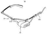
- a head mounted display 50 includes a head mounting unit 51 mounted on the user's head and an image generation unit 52 mounted on the front side of the head mounting unit 51. It is configured.
- the head mounting portion 51 shown in FIG. 11 has a nose pad 51a and an ear pad 51b, and has a frame shape of glasses.
- the image light generated by the image generation unit 52 is directly applied to the user's eyeball. The user can visually recognize the outside world at the same time as viewing the image generated by the image generation unit 52.
- Such a head mounted display 50 is expected to be frequently used in the future at the work site of a production factory. For example, if an instruction sheet, a design drawing, or the like is displayed on the image generation unit 52, the worker can perform a more reliable work by browsing the instruction sheet, the design drawing, or the like as necessary. Since the operator does not need to pick up and view the paper medium instructions and design drawings, the instructions and design drawings displayed on the image display unit 52 can be viewed while the work is performed without stopping the work. Can see. Therefore, it is possible not only to improve workability but also to prevent work mistakes.
- Patent Document 3 a head mounted display in which an elastic member is provided between the head mounting portion and the image generating portion has been proposed.
- the elastic member can reduce the impact when the work piece collides with the image display unit.
- the possibility that the image display unit is damaged could not be completely eliminated.
- the present invention has been made to solve the above-described problems and provide a head mounted display that can prevent injury to the user and damage to the image display unit.
- a head-mounted display of the present invention includes a head-mounted unit that is mounted on a user's head, In the head mounted display having an image generation unit attached to the front side of the head mounting unit and allowing the user to visually recognize an image, A drop-off means is provided for dropping the image generation unit from the head-mounted unit when an obstacle approaches or contacts the image generation unit.
- the head mounted display according to the embodiment of the present invention is the head mounted display according to item (1).
- the drop-off means is A mounting member provided in the head mounting portion; Normally, the image generating unit is coupled to the mounting member, but when an actuation force is applied, a lock unit that releases the coupling between the image generating unit and the mounting member; An operating force applying means for applying an operating force to the locking means when electric power is applied; Proximity detection means for detecting the proximity of the obstacle to the image generation unit; When the proximity detection unit detects the proximity of the obstacle to the image generation unit, the proximity detection unit includes a power input unit that supplies power to the operating force application unit. For this reason, before the obstacle comes into contact with the image generation unit, the image generation unit can be surely dropped from the head mounting unit.
- the head mounted display according to the embodiment of the present invention is the head mounted display according to item (1).
- the drop-off means is A mounting member provided in the head mounting portion; A magnetic member attached to one of the attachment member and the image generator; A magnet attached to the other of the attachment member and the image generation unit, and coupled to the magnetic member by a magnetic force; Separating means for releasing the coupling by magnetic force by separating the magnetic member and the magnet when power is applied; Proximity detection means for detecting the proximity of the obstacle to the image generation unit; It is characterized by comprising a release driver for supplying power to the separating means when the proximity of the obstacle to the image generation unit is detected. For this reason, before the obstacle comes into contact with the image generation unit, the image generation unit can be surely dropped from the head mounting unit.
- the head mounted display according to the embodiment of the present invention is the head mounted display according to item (1),
- the drop-off means is A mounting member provided in the head mounting portion;
- An engagement protrusion that protrudes from one of the attachment member and the image generation unit and has an engagement recess in the middle of the attachment member;
- An engagement hole formed in a recess in the other of the attachment member and the image generation unit, and into which the engagement means enters, It is slidably disposed so as to protrude into the engagement hole from both sides of the engagement penetration hole, and the tip of the engagement protrusion engages with the engagement recess of the engagement protrusion, thereby holding the engagement protrusion.
- the present invention is characterized in that a drop-off means is provided for dropping the image generation unit from the head-mounted unit when an obstacle approaches or contacts the image generation unit. For this reason, when the obstacle comes close to or comes into contact with the image generation unit, the image generation unit falls out of the head-mounted unit, so that it is possible to prevent damage to the image display unit and injury to the operator. Become.
- FIG. 1 is an overall view of a head mounted display showing an embodiment of the present invention. It is a block diagram of a head mounted display. It is sectional drawing of an image generation part. It is a perspective view of the principal part in 1st Embodiment. It is sectional drawing of the principal part in 1st Embodiment. It is a perspective view of the principal part in 2nd Embodiment. It is sectional drawing of the principal part in 2nd Embodiment. It is a perspective view of the principal part in 3rd Embodiment. It is a transverse cross section of the important section in a 3rd embodiment. It is a longitudinal cross-sectional view of the principal part in 3rd Embodiment. It is explanatory drawing of the head mounted display which shows conventional embodiment.
- the head mounted display 100 (shown in FIG. 2) is composed of a head mounted display main body 10 and a control unit 40.
- the head mounted display main body 10 includes a head mounting unit 1 that is mounted on the user's head and an image generation unit 2 that allows the user to visually recognize an image.
- the head mounting portion 1 shown in FIG. 1 has a frame shape of eyeglasses and includes a front frame 1a, a temple 1b, a nose pad 1c, and an ear pad 1d.
- a nose pad 1c is attached to the center of the front frame 1a.
- temples 1b are rotatably attached so as to be folded inward from a substantially vertical state with respect to the front frame 1a.
- the control unit 40 can be attached to the user's body such as the user's waist.
- the control unit 40 and the image generation unit 2 are connected by a cable 8.
- An image / control signal transmission line 8 a is disposed in the cable 8.
- An image generation unit 2 is attached to the front side of the head mounting unit 1 via an attachment member 3.
- the attachment member 3 is fixed to the front end of the temple 1b.
- the attachment member 3 may be structured to be fixed to the end portion adjacent to the temple 1b of the front frame 1a.
- a proximity sensor 4 is provided at the front end of the image generation unit 2.
- the proximity sensor 4 acts as a proximity detection unit that detects the proximity of an obstacle to the image generation unit 2 in a non-contact manner.
- the proximity sensor 4 includes a high-frequency transmission type using electromagnetic induction, a magnetic type using a magnet, an electrostatic capacitance type using a change in capacitance, an infrared detection type sensing infrared reflected light, and an ultrasonic reflected wave.
- Proximity sensors such as an ultrasonic detection type that detect
- the cable 8 extends from the rear end of the image generation unit 2.
- a wire rod support member 9 is attached to the temple 1b.
- a support hole 9 a is formed in the wire support member 9 so as to communicate therewith.
- the cable 8 is inserted into the support hole 9 a of the wire support member 9 and supported by the wire support member 9.
- a wire support 1f is formed on the ear pad 1d. The cable 8 is supported by the wire support portion 1f.
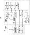
- the image generation unit 2 includes a control unit 40.
- the control unit 40 includes a CPU 41, a RAM 42, a ROM 43, a nonvolatile memory 44, a peripheral interface 46, an image input interface 47, a VRAM 48, a controller 49, and a release driver 65. These are connected to each other by a bus 55.
- the proximity sensor 4 is also connected to the bus 55.
- CPU abbreviation of Central ProcessSSing Unit 41 performs various calculations and processing in cooperation with RAM (abbreviation of Random AccessSS Memory) 42 and ROM (abbreviation of Read Only Memory) 43.
- the RAM 42 temporarily stores programs processed by the CPU 41 and data processed by the CPU 41 in its address space.
- the ROM 43 stores various programs and parameters for controlling the head mounted display main body 10.
- the various programs are processed by the CPU 41 to realize various functions.
- the nonvolatile memory 44 stores various settings of the head mounted display 1.
- the controller 49 is connected to the scanning image light irradiation unit 30, the VRAM 48, and the bus 55.
- the controller 49 has a so-called GPU (Graphics Processing Unit), and “irradiation image” is pixel data based on “image data” and “image signal” acquired from a personal computer (PC) 91 or the like via a wireless LAN. Data ”is generated and stored in the VRAM 48.
- the controller 49 outputs the “irradiation image data” as the “image signal” to the scanning image light irradiation unit 30.
- the controller 49 also outputs a “control signal” to the separate scanning image light irradiation unit 30 via the image / control signal transmission line 8a.
- the control signal includes control signals such as turning on / off the power of the scanning image light irradiation unit 30 and adjusting the image position.
- the image input interface 47 is connected to the VRAM 48 and the bus 55.
- the image input interface 47 has a wireless interface, and is connected to a device or network that outputs “image signals” and “image data” such as a PC 91 and a local area network (LAN) by a wireless LAN.
- “Image signal” and “image data” are input to the image input unit interface 47.
- the image input interface 47 converts the physical or logical format of the “image signal” or “image data” into “ It is stored in the VRAM 48 as “image data”.
- Peripheral interface 46 converts the physical and logical format of the signal.
- An operation unit 60 and a power lamp 61 are connected to the peripheral interface 46.
- the operation unit 60 is for operating the head mounted display 100.
- the operation includes an operation of turning the head mounted display 100 on and off.
- the power lamp 61 is lit when the head mounted display 100 is in an ON state.
- the proximity sensor 4 When the proximity sensor 4 detects the proximity of the detected object, the proximity sensor 4 outputs a “detection signal” to the bus 55.
- the “detection signal” is stored in the storage area of the RAM 42.
- the proximity sensor 4 is proximity detection means for detecting proximity to the obstacle image generation unit 2.
- the release driver 65 is a drive circuit that supplies electric power to the actuator 7.
- the release driver 65 serves as power input means for supplying power to the actuator 7 when the proximity sensor 4 detects the proximity of the obstacle to the image generation unit 2.
- the scanned image light irradiation unit 30 generates scanned image light obtained by two-dimensionally scanning light whose intensity is modulated according to the image.
- the scanning image light irradiation unit 30 causes the user to visually recognize an image by directly irradiating the user's eyeball with the scanning image light.
- the scanning image light irradiation unit 30 includes a light source 31, a collimating optical system 32, a scanning light generation unit 33, an eyepiece lens 34, and a mirror 35.
- the light source 31 is a device that generates light such as laser light by modulating the intensity in accordance with the “image signal” read by the controller 49 for each dot clock.
- the collimating optical system 32 collimates the light generated by the light source 31 and emits it to the scanning light generation unit 33.
- the scanning light generation unit 33 In order to irradiate the incident light as an image, the scanning light generation unit 33 generates the scanning image light by scanning the light in the horizontal direction and the vertical direction based on the signal output from the controller 49.
- the eyepiece 34 has lens systems 34a and 34b having positive refractive power.
- the scanning image light emitted from the scanning light generation unit 33 is made parallel to each other by the lens system 34a so that the respective scanning image lights have their center lines parallel to each other.
- the scanning image light that has been made substantially parallel is condensed by the lens system 34b so that the center line of these scanning image light converges on the pupil Ea of the user.
- the condensed scanning image light is reflected by the mirror 35 and converges on the pupil Ea of the user.
- control unit 40 and the image generation unit 2 are separated from each other, and the control unit 40 is attached to the user's body.
- the control unit 40 is provided in the image generation unit 2 and has an integrated structure may be used.
- the cable 8 is replaced with a fall prevention cable and attached to the temple 1b.
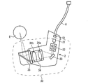
- the attachment member 3 includes a vertical plate portion 3a and an attachment portion 3b extending horizontally from the lower end of the vertical plate portion 3a.
- a closing plate portion 3 c connected to the middle portion of the vertical plate portion 3 a and spaced apart in parallel above the attachment portion 3 b is formed.
- the upper portion of the vertical plate portion 3a is a fixing portion 3d that is fixed to the front end of the temple 1b.
- a pin hole 3e and a lock hole 3f are formed in communication with the mounting portion 3b.
- the cross-sectional shape of the lock hole 3f is a rectangular shape (including a square).
- two pin holes 3e and two lock holes 3f are formed at predetermined intervals.
- a mounting recess 2 a that opens upward is formed in the rear upper surface of the image generation unit 2. Since the mounting recess 2a has a shape corresponding to the outer edge shape of the mounting portion 3b of the mounting member 3, the mounting portion 3b can enter the mounting recess 2a.
- Two pins 2b protrude from the bottom surface of the mounting recess 2a at a predetermined interval.
- the pin 2 b enters the pin hole 3 e of the attachment member 3.
- the tip of the pin 2b has a sharp shape so that it can easily enter the pin hole 3e.
- Two through holes 2c are formed on the bottom surface of the mounting recess 2a at a predetermined interval.
- a coil spring 2d is attached to the bottom surface of the attachment recess 2a. The coil spring 2d is compressed in the vertical direction.
- the lock member 5 is housed inside the image generation unit 2 so as to be slidable in the lateral direction.
- the lock member 5 is formed with a plate-like lock portion 5a at a predetermined interval.
- the lock portion 5a passes through a through hole 2c formed in the bottom surface of the mounting recess 2a and protrudes outside from the through hole 2c.
- a lock projection 5b On one side of the distal end of the lock portion 5a, a lock projection 5b having a shape in which the lateral width gradually increases from the distal end of the lock portion 5a toward the proximal end side is projected.
- An inclined surface 5d is formed on the lock protrusion 5b from the distal end of the lock portion 5a toward the proximal direction.
- a locking surface 5c that is a horizontal surface that intersects the lock portion 5a perpendicularly is formed at the lower end of the lock protrusion 5b.
- a spring 6 is housed inside the image generation unit 2. One end of the spring 6 is attached to the inner wall of the image generator 2. The other end of the spring 6 is attached to the lock member 5. The spring 6 biases the lock member 5 to the side where the lock projection 5b is projected.
- An electric actuator 7 is attached inside the image generator 2.
- the actuator 7 has a shaft 7a that slides in the lateral direction.
- the tip of the shaft 7 a is fixed to the lock member 5.
- the actuator 7 is an actuating force applying means for applying an actuating force to a lock means to be described later when electric power is turned on.
- the pin 2b is inserted into the pin hole 3e, and the image generation unit 2 Is moved to the mounting member 3 side. Then, the tip of the lock portion 5a enters the lock hole 3f while the pin 2b is guided in the pin hole 3e. At this time, the inclined surface 5d of the lock projection 5b contacts the side surface of the lock hole 3f, and the slide member 5 slides in a direction opposite to the projecting direction of the lock projection 5b, while the lock projection 5b enters the lock hole 3f. invade.
- the sliding member 5 slides to the side where the locking projection 5b is projected by the urging force of the spring 6 and enters the locked state (the state shown in FIG. 5).
- the image generator 2 is coupled to the mounting member 3.
- the coil spring 2d comes into contact with the mounting portion 3b and is compressed.
- the locked state the locking surface 5c is in close contact with the upper surface of the mounting portion 3b, and the lock protrusion 5b cannot get over the lock hole 3f. Therefore, in the locked state, the image generation unit 2 does not come off from the attachment member 3.
- the locking means for coupling the image generating unit 2 to the mounting member 3 includes the locking member 5 and the lock hole 3 f formed in the mounting member 3.
- the lock unit releases the coupling between the image generation unit 2 and the attachment member 3 when the operation force is applied by the actuator 7 which is the operation force application unit.
- the locking means is not limited to the structure shown in FIGS. 4 and 5, and the image generating unit 2 is normally coupled to the mounting member 3, but when the operating force is applied, the image generating unit 2 Any structure that releases the coupling with the attachment member 3 is included.
- the proximity sensor 4 detects the proximity of an obstacle
- a signal is input from the CPU 41 to the release driver 65, and the release driver 65 supplies power to the actuator 7.
- the image generation unit 2 does not fall off the mounting member 3, and the obstacle and the image generation unit 2 do not collide.
- the cable 8 is supported by the wire support member 9, so that the image generation unit 2 does not fall and is suspended by the cable 8. For this reason, the image generation unit 2 is not damaged.
- the head mounted display of 2nd Embodiment is demonstrated about a different point from 1st Embodiment using FIG.6 and FIG.7.
- the structure of the head mounting part 1 of the second embodiment is the same as that of the head mounting part 1 of the first embodiment.
- the attachment member 13 is composed of a vertical plate portion 13a and a horizontal plate portion 13b extending horizontally from the lower end of the vertical plate portion 13a.
- the upper part of the vertical plate part 13a is a fixing part 13d fixed to the front end of the temple 1b.
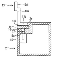
- a plate-like magnetic member 14 such as an iron plate is attached to the lower surface of the horizontal plate portion 13b.
- a mounting recess 2 e opened upward is formed in the rear upper surface of the image generator 2 so as to be recessed. Since the mounting recess 2e has a shape corresponding to the outer edge shape of the horizontal portion 13b and the magnetic member 14 of the mounting member 13, the horizontal portion 13b and the magnetic member 14 can enter the mounting recess 2e.
- a magnet 16 that is a plate-like magnet is attached to the bottom surface of the mounting recess 2e.
- the magnet 16 attracts the magnetic member 14 attached to the attachment member 13 by magnetic force, whereby the image generation unit 2 is coupled to the attachment member 13.
- two through holes 16 a are formed through the magnet 16.
- a communication hole 2 f that communicates with the inside of the image generation unit 2 is formed at a position corresponding to the through hole 16 a on the bottom surface of the mounting recess 2 e.
- an actuator 15 is attached inside the image generation unit 2.
- the actuator 15 is a push solenoid having a pusher 15a that slides in the vertical direction.
- the pusher 15a slides upward.
- the pusher 15 a protrudes from the through hole 16 a of the magnet 16 and presses the magnetic member 14.
- the magnetic member 14 is pressed by the pusher 15a, the magnetic member 14 and the magnet 16 are separated from each other, and the coupling by the magnetic force between the magnetic member 14 and the magnet 16 is released.
- the image generating unit 2 is detached from the attachment member 13.
- the separation means for releasing the coupling of the magnetic member 14 and the magnet 16 by the magnetic force is constituted by the actuator 15 having the pusher 15a.
- the separation means is not limited to such a configuration, and includes any structure that separates the magnetic member 14 and the magnet 16 from each other.
- the proximity sensor 4 detects the proximity of an obstacle
- a signal is input to the release driver 65, and the release driver 65 supplies power to the actuator 15.
- the pusher 15a presses the magnetic member 14, and as described above, the image generating unit 2 is dropped from the mounting member 13, and the obstacle and the image generating unit 2 do not collide. Even if the image generation unit 2 falls off the attachment member 13, the cable 8 is supported by the wire support member 9, so that the image generation unit 2 does not fall and is suspended by the cable 8. For this reason, the image generation unit 2 is not damaged.
- the magnetic member 14 is attached to the lower surface of the horizontal portion 13b of the attachment member 13.
- the mounting member 13 is made of a magnetic material, the magnetic member 14 is not necessary.
- the magnet 16 may be attached to the attachment member 13 side and the magnetic member 14 may be attached to the image generation unit 2 side.
- the head mounted display according to the third embodiment will be described with respect to differences from the first embodiment with reference to FIGS.
- the structure of the head mounting part 1 of the third embodiment is the same as that of the head mounting part 1 of the first embodiment.
- the proximity sensor 4, the release driver 65, and the actuator are not necessary.
- the mounting member 23 includes a vertical plate portion 23a and a horizontal plate portion 23b extending horizontally from the lower end of the vertical plate portion 23a.
- the upper part of the vertical plate part 23a is a fixing part 23d fixed to the front end of the temple 1b.
- Engagement projections 23e project from the lower surface of the horizontal plate portion 23b.
- Engagement recesses 23f are formed on both sides of the middle portion of the engagement protrusion 23e.
- the front end 23h of the engagement protrusion 23e is wider than the width of the portion of the engagement protrusion 23e where the engagement recess 23f is formed.
- a pressing protrusion 23g protrudes at a position where an engaging recess 23f is formed on the surface of the engaging protrusion 23e. In the embodiment shown in FIGS. 8 to 10, the pressing protrusions 23g are provided so as to protrude vertically on both surfaces of the engaging protrusion 23e.
- a mounting recess 2 g opened upward is formed in the base of the image generating unit 2. Since the mounting recess 2g has a shape corresponding to the outer edge shape of the horizontal portion 23b of the mounting member 23, the horizontal portion 23b can enter the mounting recess 2g. On the bottom surface of the mounting recess 2g, an engagement hole 2h communicating with the inside of the image generating unit 2 is formed. The engagement hole 2h has a long hole shape or a rectangular shape. The engagement protrusion 23e can enter the engagement hole 2h.
- a pair of slide members 24 are opposed to each other at the tip of the image generation unit 2 so as to protrude directly below the engagement hole 2h from both directions below the engagement hole 2h. In addition, it is slidable in the lateral direction.
- the distal ends 24a of the pair of slide members 24 are located immediately below the engagement holes 2h.
- a substantially arc-shaped leaf spring 25 is attached to the tip 24 a portion of the pair of slide members 24 with a pin 26.
- the leaf spring 25 bulges in the direction of the engagement hole 2h.
- the pair of slide members 24 are urged by the leaf springs 25 in directions close to each other. Therefore, the pair of slide members 24 are attracted. As shown in FIG. 9A, the leaf spring 25 is separated from the slide member 24.
- the engaging protrusion 23e is inserted into the engaging hole 2h (state (A) in FIG. 10). Then, the front end 23h of the engagement protrusion 23e pushes and expands the front end 24a of the slide member 24 attracted to each other. When the distal end portion 23h of the engagement protrusion 23e gets over the distal ends 24a of the pair of slide members 24, the distal ends 24a of the pair of slide members 24 sandwich the engagement recesses 23f of the engagement protrusion 23e ((B in FIG. 10). ) State).
- the shape of the tip 24a of the slide member 24 is a shape corresponding to the engagement recess 23f of the engagement protrusion 23e.
- the front ends 24a of the pair of slide members 24 are engaged with the engagement recesses 23f of the engagement protrusions 23e, and the image generation unit 2 and the attachment member 23 are coupled.
- the pair of slide members 24 and the engagement protrusions 23e are arranged in a straight line.
- the pressing protrusion 23g presses the leaf spring 25 when the tip 23h of the engaging protrusion 23e pushes and expands the tip 24a of the slide member 24 attracted to each other.
- the leaf spring 25 is deformed as shown in FIG. In a state where the engaging protrusion 23e and the pair of slide members 24 are engaged, the leaf spring 25 biases the engaging protrusion 23e upward.
- the image generation unit 2 generates scanning image light obtained by two-dimensionally scanning light whose intensity is modulated in accordance with the image, and directly irradiates the user's eyeball with the scanned image light, thereby causing the image to the user.
- the image generation unit 2 of the present invention is not limited to this, and includes any device that uses a display device such as an LCD and allows the user to visually recognize an image.
- one image generation unit 2 is attached to the front side of the head mounting unit 1.
- the two image generation units 2 are attached to the front portions on both sides of the head mounting unit 1 and the user can visually recognize images with both eyes.
- the head mounting portion 1 of the head mounted display described above has a frame shape of glasses.
- the head mounting portion 1 is not limited to this shape, and may be a helmet shape or the like, and includes any structure that is mounted on the user's head. It goes without saying that the present invention can also be applied to a head-mounted display having such a structure.
Landscapes
- Physics & Mathematics (AREA)
- General Physics & Mathematics (AREA)
- Optics & Photonics (AREA)
Abstract
ユーザの怪我及び画像表示部の破損を防止することができるヘッドマウントディスプレイを提供する。 ユーザの頭部に装着される頭部装着部1と、頭部装着部1の前側方に取り付けられ、ユーザに画像を視認させる画像生成部2を有するヘッドマウントディスプレイにおいて、画像生成部2と頭部装着部1をロック手段で結合させ、障害物が画像生成部2に近接した際に、近接センサー4が検知すると、アクチュエータが、ロック手段の結合を解除することにより、画像生成部2を頭部装着部1から脱落させる。
Description
本発明は、ユーザの頭部に装着して、画像を見ることができるヘッドマウントディスプレイに関するものである。
従来から、特許文献1や特許文献2に示されるようなヘッドマウントディスプレイが知られている。このようなヘッドマウントディスプレイ50は、図11に示されるように、ユーザの頭部に装着される頭部装着部51と、頭部装着部51の前側方に取り付けられた画像生成部52とから構成されている。図11に示される頭部装着部51は、ノーズパッド51a及びイヤーパッド51bを有し、メガネのフレーム形状をしている。画像生成部52で生成された画像光は、直接ユーザの眼球に照射される。ユーザは、画像生成部52が生成する画像を視認すると同時に、外界を視認することができる。
このようなヘッドマウントディスプレイ50は、今後、生産工場の作業現場等で多用されることが想定される。例えば、画像生成部52に指示書や設計図等を表示させれば、作業者は、必要に応じて指示書や設計図等を閲覧することにより、より確実な作業を行うことができる。作業者は、紙媒体の指示書や設計図を手に取って閲覧する必要がないので、作業を中止することなく、作業をしながら、画像表示部52に表示された指示書や設計図を見ることができる。そのため、作業性の向上だけでなく、作業ミスの防止も可能となる。
しかし、作業者が集中して作業を行うと、作業者の顔が被作業物に近づき過ぎることがある。その結果、この被作業物と画像表示部52が衝突し、画像表示部52が破損する可能性がある。
そこで、特許文献3に示されるように、頭部装着部と画像生成部との間に弾性部材を設けたヘッドマウントディスプレイが提案されている。このヘッドマウントディスプレイでは、被作業物と画像表示部が衝突した際の衝撃を、前記弾性部材が吸収することにより低減することができる。しかし、画像表示部が破損する可能性を完全に排除することができなかった。
本発明は、上記問題を解決し、ユーザの怪我及び画像表示部の破損を防止することができるヘッドマウントディスプレイを提供するためになされたものである。
(1) 上記課題を解決するために、本発明のヘッドマウントディスプレイは、ユーザの頭部に装着される頭部装着部と、
前記頭部装着部の前側方に取り付けられ、前記ユーザに画像を視認させる画像生成部を有するヘッドマウントディスプレイにおいて、
障害物が前記画像生成部に近接又は接触した際に、前記画像生成部を前記頭部装着部から脱落させる脱落手段を設けたことを特徴とする。
前記頭部装着部の前側方に取り付けられ、前記ユーザに画像を視認させる画像生成部を有するヘッドマウントディスプレイにおいて、
障害物が前記画像生成部に近接又は接触した際に、前記画像生成部を前記頭部装着部から脱落させる脱落手段を設けたことを特徴とする。
(2) 本発明の実施形態のヘッドマウントディスプレイは、(1)項に記載のヘッドマウントディスプレイにおいて、
脱落手段は、
頭部装着部に設けられた取付部材と、
常時は画像生成部を前記取付部材に結合させているが、作動力が付与されると、画像生成部と前記取付部材との結合を解除するロック手段と、
電力が投入された際に、前記ロック手段に作動力を付与する作動力付与手段と、
障害物の画像生成部への近接を検知する近接検知手段と、
前記近接検知手段が障害物の画像生成部への近接を検知した際に、前記作動力付与手段に電力を投入する電力入力手段とから構成されることを特徴とする。
このため、障害物が前記画像生成部に接触する前に、確実に、前記画像生成部を前記頭部装着部から脱落させることが可能となる。
脱落手段は、
頭部装着部に設けられた取付部材と、
常時は画像生成部を前記取付部材に結合させているが、作動力が付与されると、画像生成部と前記取付部材との結合を解除するロック手段と、
電力が投入された際に、前記ロック手段に作動力を付与する作動力付与手段と、
障害物の画像生成部への近接を検知する近接検知手段と、
前記近接検知手段が障害物の画像生成部への近接を検知した際に、前記作動力付与手段に電力を投入する電力入力手段とから構成されることを特徴とする。
このため、障害物が前記画像生成部に接触する前に、確実に、前記画像生成部を前記頭部装着部から脱落させることが可能となる。
(3) 本発明の実施形態のヘッドマウントディスプレイは、(1)項に記載のヘッドマウントディスプレイにおいて、
脱落手段は、
頭部装着部に設けられた取付部材と、
前記取付部材及び画像生成部の一方に取り付けられた磁性部材と、
前記取付部材及び画像生成部の他方に取り付けられ、前記磁性部材と磁力により結合させるマグネットと、
電力が投入された際に、前記磁性部材と前記マグネットとを離間させることにより、磁力による結合を解除させる離間手段と、
障害物の画像生成部への近接を検知する近接検知手段と、
障害物の画像生成部への近接を検知した際に、前記離間手段に電力を投入するリリースドライバとから構成されることを特徴とする。
このため、障害物が前記画像生成部に接触する前に、確実に、前記画像生成部を前記頭部装着部から脱落させることが可能となる。
脱落手段は、
頭部装着部に設けられた取付部材と、
前記取付部材及び画像生成部の一方に取り付けられた磁性部材と、
前記取付部材及び画像生成部の他方に取り付けられ、前記磁性部材と磁力により結合させるマグネットと、
電力が投入された際に、前記磁性部材と前記マグネットとを離間させることにより、磁力による結合を解除させる離間手段と、
障害物の画像生成部への近接を検知する近接検知手段と、
障害物の画像生成部への近接を検知した際に、前記離間手段に電力を投入するリリースドライバとから構成されることを特徴とする。
このため、障害物が前記画像生成部に接触する前に、確実に、前記画像生成部を前記頭部装着部から脱落させることが可能となる。
(4) 本発明の実施形態のヘッドマウントディスプレイは、(1)項1に記載のヘッドマウントディスプレイにおいて、
脱落手段は、
頭部装着部に設けられた取付部材と、
前記取付部材及び画像生成部の一方に突設され、その途中部分に係合凹部を有する係合突起と、
前記取付部材及び画像生成部の他方に凹陥形成され、前記係合手段が侵入する係合穴と、
前記係合侵入穴の両側方から、前記係合穴内に突出するようにスライド自在に配設され、その先端が前記係合突起の係合凹部に係合することで、前記係合突起を挟持する一対の挟持部材と、
前記一対の挟持部材を、互いに近接させる方向に付勢する付勢部材とから構成されることを特徴とする。
このため、電子・電気部品を使用することなく、機械的な構造のみで、脱落手段を実現することができ、過大にコストアップにならずに、ヘッドマウントディスプレイを提供することが可能となる。
脱落手段は、
頭部装着部に設けられた取付部材と、
前記取付部材及び画像生成部の一方に突設され、その途中部分に係合凹部を有する係合突起と、
前記取付部材及び画像生成部の他方に凹陥形成され、前記係合手段が侵入する係合穴と、
前記係合侵入穴の両側方から、前記係合穴内に突出するようにスライド自在に配設され、その先端が前記係合突起の係合凹部に係合することで、前記係合突起を挟持する一対の挟持部材と、
前記一対の挟持部材を、互いに近接させる方向に付勢する付勢部材とから構成されることを特徴とする。
このため、電子・電気部品を使用することなく、機械的な構造のみで、脱落手段を実現することができ、過大にコストアップにならずに、ヘッドマウントディスプレイを提供することが可能となる。
本発明は、障害物が前記画像生成部に近接又は接触した際に、前記画像生成部を前記頭部装着部から脱落させる脱落手段を設けたことを特徴とする。
このため、障害物が前記画像生成部に近接又は接触した際に、画像生成部が、頭部装着部から脱落するので、画像表示部の破損や、作業者の怪我を防止することが可能となる。
このため、障害物が前記画像生成部に近接又は接触した際に、画像生成部が、頭部装着部から脱落するので、画像表示部の破損や、作業者の怪我を防止することが可能となる。
(ヘッドマウントディスプレイの構造)
以下に、図面を参照しつつ本発明の好ましい実施の形態を示す。ヘッドマウントディスプレイ100(図2に示す)は、ヘッドマウントディスプレイ本体10と制御部40とから構成されている。図1に示されるように、ヘッドマウントディスプレイ本体10は、ユーザの頭部に装着される頭部装着部1と、ユーザに画像を視認させる画像生成部2とから構成されている。図1に示される頭部装着部1は、眼鏡のフレーム形状をしていて、フロントフレーム1a、テンプル1b、ノーズパッド1c、イヤーパッド1dとから構成されている。フロントフレーム1aの中央部には、ノーズパッド1cが取り付けられている。フロントフレーム1aの両端には、テンプル1bが、フロントフレーム1aに対して略垂直の状態から内側に折り畳めるように、回動自在に取り付けられている。
以下に、図面を参照しつつ本発明の好ましい実施の形態を示す。ヘッドマウントディスプレイ100(図2に示す)は、ヘッドマウントディスプレイ本体10と制御部40とから構成されている。図1に示されるように、ヘッドマウントディスプレイ本体10は、ユーザの頭部に装着される頭部装着部1と、ユーザに画像を視認させる画像生成部2とから構成されている。図1に示される頭部装着部1は、眼鏡のフレーム形状をしていて、フロントフレーム1a、テンプル1b、ノーズパッド1c、イヤーパッド1dとから構成されている。フロントフレーム1aの中央部には、ノーズパッド1cが取り付けられている。フロントフレーム1aの両端には、テンプル1bが、フロントフレーム1aに対して略垂直の状態から内側に折り畳めるように、回動自在に取り付けられている。
制御部40は、ユーザの腰等のユーザの身体に取り付けられるようになっている。制御部40と画像生成部2とはケーブル8で接続している。なお、ケーブル8内には、画像・制御信号伝送線8aが配設されている。
頭部装着部1の前側方には、取付部材3を介して、画像生成部2が取り付けられている。図1に示される実施形態では、取付部材3は、テンプル1bの前端に固着している。しかし、取付部材3が、フロントフレーム1aのテンプル1bに隣接する端部に固着している構造であっても差し支えない。画像生成部2の前端には、近接センサー4が設けられている。近接センサー4は、障害物の画像生成部2への近接を、非接触で検知する近接検知手段として作用する。近接センサー4には、電磁誘導を利用した高周波発信型、磁石を用いた磁気型、静電容量の変化を利用した静電気容量型、赤外線の反射光をセンシングする赤外線検知型、超音波の反射波を検知する超音波検知型等の近接センサーが含まれる。
画像生成部2の後端からケーブル8が、延出している。テンプル1bには、線材支持部材9が取り付けられている。線材支持部材9には、支持穴9aが連通形成されている。ケーブル8は、線材支持部材9の支持穴9aに挿通し、線材支持部材9で支持されている。イヤーパッド1dには、線材支持部1fが形成されている。当該線材支持部1fで、ケーブル8を支持している。
図2に示されるように、画像生成部2は、制御部40を有している。制御部40は、CPU41、RAM42、ROM43、不揮発性メモリー44、周辺インターフェース46、画像入力インターフェース47、VRAM48、コントローラ49、リリースドライバ65を有する。これらは相互にバス55で接続されている。また、近接センサー4も、バス55に接続している。
CPU(Central ProceSSing Unitの略)41は、RAM(Random AcceSS Memoryの略)42、ROM(Read Only Memoryの略)43と協動して、各種演算、処理を行う。
RAM42は、CPU41によって処理されるプログラムや、CPU41で処理するデータを、そのアドレス空間に一時的に保存する。
ROM43には、ヘッドマウントディスプレイ本体10を制御する各種プログラムやパラメータが保存されている。当該各種プログラムが、CPU41で処理されることにより、各種機能を実現している。
不揮発性メモリー44は、ヘッドマウントディスプレイ1の各種設定を保存する。
コントローラ49は、走査画像光照射部30及び、VRAM48、バス55と接続している。コントローラ49は、所謂GPU(Graphics Processing Unit)を有し、無線LANを介してパーソナルコンピュータ(PC)91等から取得した「画像データ」や「画像信号」に基づいて、ピクセルデータである「照射画像データ」を生成し、VRAM48に保存する。コントローラ49は、前記「照射画像データ」を「画像信号」として走査画像光照射部30に出力する。また、コントローラ49は、別体である走査画像光照射部30に、画像・制御信号伝送線8aを介して「制御信号」を出力する。制御信号には、走査画像光照射部30の電力の投入・遮断、画像位置の調整等の制御信号が含まれる。
画像入力インターフェース47は、VRAM48及びバス55と接続している。画像入力インターフェース47は無線インターフェースを有していて、PC91や、ローカルエリアネットワーク(LAN)等の「画像信号」や「画像データ」を出力する機器又はネットワークに無線LANにより接続している。画像入力部インターフェース47には、「画像信号」や「画像データ」が、入力されるようになっている。画像入力部に「画像信号」や「画像データ」が入力された場合には、画像入力インターフェース47は、当該「画像信号」や「画像データ」の物理的や論理的な形式を変換して「画像データ」としてVRAM48に保存する。
周辺インターフェース46は、信号の物理的、論理的な形式を変換する。周辺インターフェース46には、操作部60、電源ランプ61が接続している。操作部60は、ヘッドマウントディスプレイ100の操作を行うためのものである。前記操作には、ヘッドマウントディスプレイ100をON・OFF状態にする操作が含まれる。電源ランプ61は、ヘッドマウントディスプレイ100がON状態の時に点灯するようになっている。
近接センサー4が被検出物体の近接を検出した場合には、近接センサー4は「検出信号」をバス55に出力する。当該「検出信号」はRAM42の記憶領域に保存される。近接センサー4は、障害物の画像生成部2へ近接を検知する近接検知手段となっている。
リリースドライバ65は、アクチュエータ7に、電力を供給する駆動回路である。リリースドライバ65は、近接センサー4が障害物の画像生成部2への近接を検知した際に、アクチュエータ7に電力を投入する電力入力手段となっている。
走査画像光照射部30は、強度が画像に応じて変調された光を2次元に走査した走査画像光を生成する。走査画像光照射部30は、当該走査画像光をユーザの眼球に直接照射することで、ユーザに画像を視認させる。図3に示されるように、走査画像光照射部30は、光源31、コリメート光学系32、走査光生成部33、接眼レンズ34、ミラー35を有している。
光源31は、コントローラ49がドットクロック毎に読み出した「画像信号」に応じて強度変調してレーザ光等の光を生成する装置である。
コリメート光学系32は、光源31が生成した光を、平行光化し、走査光生成部33に出射する。
走査光生成部33は、入射された光を、画像として照射するために、コントローラ49から出力された信号に基づき、当該光を水平方向と垂直方向に走査して走査画像光を生成する。
接眼レンズ34は、正の屈折力を持つレンズ系34a、34bを有している。走査光生成部33から出射された走査画像光は、レンズ系34aによって、それぞれの走査画像光が、その走査画像光の中心線を相互に略平行にされる。略平行にされた走査画像光は、レンズ系34bによって、これらの走査画像光の中心線がユーザの瞳孔Eaに収束するように集光される。集光された走査画像光は、ミラー35で反射されて、ユーザの瞳孔Eaに収束する。
本実施形態では、制御部40と画像生成部2と別体にして、制御部40をユーザの身体に取り付けている。しかし、制御部40を画像生成部2内に設け一体構造とした、実施態であっても差し支えない。このとき、ケーブル8は落下防止ケーブルに置き換えられ、テンプル1bに取り付けられる。
(第1の実施形態)
以下に、図4及び図5を用いて第1の実施形態のヘッドマウントディスプレイを説明する。図4に示されるように、取付部材3は、垂直板部3aと、この垂直板部3aの下端から水平に延出する取付部3bとから構成されている。図4に示される実施形態では、取付部3bの上方に平行に離間して垂直板部3aの途中部分に接続した閉塞板部3cが形成されている。垂直板部3aの上部は、テンプル1bの前端に固着される固着部3dとなっている。
以下に、図4及び図5を用いて第1の実施形態のヘッドマウントディスプレイを説明する。図4に示されるように、取付部材3は、垂直板部3aと、この垂直板部3aの下端から水平に延出する取付部3bとから構成されている。図4に示される実施形態では、取付部3bの上方に平行に離間して垂直板部3aの途中部分に接続した閉塞板部3cが形成されている。垂直板部3aの上部は、テンプル1bの前端に固着される固着部3dとなっている。
取付部3bには、ピン穴3e及びロック穴3fが連通形成されている。図4に示される実施形態では、ロック穴3fの断面形状は、長方形状(正方形を含む)となっている。また、図4に示される実施形態では、ピン穴3e及びロック穴3fは、所定の間隔をおいてそれぞれ2つ形成されている。
図4に示されるように、画像生成部2の後部上面には、上方に開口した、取付凹部2aが凹陥形成されている。取付凹部2aは、取付部材3の取付部3bの外縁形状に対応した形状になっているので、前記取付部3bが取付凹部2a内に侵入することができる。取付凹部2aの底面には、所定間隔をおいて2つのピン2bが突設されている。ピン2bは、取付部材3のピン穴3eに侵入するようになっている。ピン2bの先端形状は、ピン穴3e内に侵入し易いように、尖鋭な形状となっている。取付凹部2aの底面には、所定間隔をおいて、2つの貫通穴2cが形成されている。取付凹部2aの底面には、コイルスプリング2dが取り付けられている。このコイルスプリング2dは、上下方向に圧縮されるようになっている。
図5に示されるように、画像生成部2の内部には、ロック部材5が横方向にスライド自在に収納されている。ロック部材5には、所定間隔をおいて、板状のロック部5aが形成されている。図5に示されるように、ロック部5aは、取付凹部2aの底面に形成された貫通穴2cを貫通して、この貫通穴2cから外部に突出している。ロック部5aの先端の片面には、ロック部5aの先端から基端側に向けて徐々に横幅が広くなっている形状のロック突起5bが突設されている。ロック突起5bには、ロック部5aの先端から基端方向に向かって、傾斜面5dが形成されている。ロック突起5bの下端には、ロック部5aと垂直に交わる水平な面の係止面5cが形成されている。
画像生成部2の内部には、スプリング6が収納されている。スプリング6の一端は、画像生成部2の内壁に取り付けられている。スプリング6の他端は、ロック部材5に取り付けられている。スプリング6は、ロック部材5を、ロック突起5bが突設されている側に、付勢している。
画像生成部2の内部には、電動式のアクチュエータ7が取り付けられている。このアクチュエータ7は、横方向にスライドするシャフト7aを有している。シャフト7aの先端は、ロック部材5に固着している。アクチュエータ7に電力を投入すると、シャフト7aが、ロック突起5bの突設方向と反対側にスライドする。アクチュエータ7は、電力が投入された際に、後述するロック手段に作動力を付与する作動力付与手段となっている。
頭部装着部1と画像生成部2が分離している状態から、画像生成部2を頭部装着部1に取り付けるには、ピン2bをピン穴3eに挿入させるようにして、画像生成部2を取付部材3側に移動させる。すると、ピン2bがピン穴3eにガイドされながら、ロック部5aの先端が、ロック穴3f内に侵入する。この際に、ロック突起5bの傾斜面5dが、ロック穴3fの側面と当接し、スライド部材5がロック突起5bの突設方向と反対方向にスライドしながら、ロック突起5bがロック穴3f内に侵入する。ロック突起5bの係止面5cがロック穴3fを乗り越えると、スプリング6の付勢力により、スライド部材5がロック突起5bの突設されている側にスライドし、ロック状態となり(図5の状態)、画像生成部2が取付部材3に結合される。この際に、コイルスプリング2dは、取付部3bと当接して、圧縮される。ロック状態では、係止面5cが取付部3bの上面と密接し、ロック突起5bがロック穴3fを乗り越えることができない。そのため、ロック状態では、画像生成部2が取付部材3から外れることがない。
画像生成部2が取付部材3を介して頭部装着部1に取り付けられている状態において、アクチュエータ7に電力が投入されると、シャフト7aがスライドして、ロック部材5が、ロック突起5bの突設方向と反対側にスライドする。このロック部材5のスライドにより、ロック突起5bがロック穴3fを乗り越えることができる状態となり、画像生成部2と取付部材3との結合状態が解除される。画像生成部2は、コイルスプリング2dの付勢力や重力により、取付部材3から離脱する。
このように、画像生成部2を取付部材3に結合させるロック手段は、ロック部材5と、取付部材3に形成されたロック穴3fとから構成されている。ロック手段は、作動力付与手段であるアクチュエータ7により作動力が付与されると、画像生成部2と取付部材3との結合を解除する。ロック手段は、図4や図5に示されるような構造に限定されず、常時は画像生成部2を取付部材3に結合させているが、作動力が付与されると、画像生成部2と取付部材3との結合を解除する構造のものであれば全て含まれる。
近接センサー4が障害物の近接を検知すると、CPU41からリリースドライバ65に信号が投入され、リリースドライバ65がアクチュエータ7に電力を投入する。すると、シャフト7aがスライドすることにより、前述したように、画像生成部2が取付部材3から脱落し、障害物と画像生成部2とが衝突することがない。画像生成部2が取付部材3から脱落しても、線材支持部材9により、ケーブル8が支持されているので、画像生成部2が落下することがなく、ケーブル8で吊された状態となる。このため、画像生成部2が破損することがない。
(第2の実施形態)
以下に、図6及び図7を用いて、第1の実施形態と異なる点について第2の実施形態のヘッドマウントディスプレイを説明する。第2の実施形態の頭部装着部1の構造は、第1の実施形態の頭部装着部1と同一である。図6に示されるように、取付部材13は、垂直板部13aと、この垂直板部13aの下端から水平に延出する水平板部13bとから構成されている。垂直板部13aの上部は、テンプル1bの前端に固着される固着部13dとなっている。
以下に、図6及び図7を用いて、第1の実施形態と異なる点について第2の実施形態のヘッドマウントディスプレイを説明する。第2の実施形態の頭部装着部1の構造は、第1の実施形態の頭部装着部1と同一である。図6に示されるように、取付部材13は、垂直板部13aと、この垂直板部13aの下端から水平に延出する水平板部13bとから構成されている。垂直板部13aの上部は、テンプル1bの前端に固着される固着部13dとなっている。
水平板部13bの下面には、鉄板等の板状の磁性部材14が取り付けられている。
図6に示されるように、画像生成部2の後部上面には、上方に開口した、取付凹部2eが凹陥形成されている。取付凹部2eは、取付部材13の水平部13b及び磁性部材14の外縁形状に対応した形状になっているので、水平部13b及び磁性部材14が取付凹部2e内に侵入することができる。
取付凹部2eの底面には、板状のマグネットであるマグネット16が取り付けられている。マグネット16が磁力により取付部材13に取り付けられた磁性部材14を吸着することで、画像生成部2が取付部材13に結合される。
図6、図7に示される第2の実施形態では、2つの貫通穴16aが、マグネット16に貫通形成されている。図7に示されるように、取付凹部2eの底面の貫通穴16aに対応する位置には、画像生成部2の内部に連通する連通穴2fが形成されている。
図7に示されるように、画像生成部2の内部には、アクチュエータ15が取り付けられている。図7に示される第2の実施形態では、アクチュエータ15は、上下方向にスライドするプッシャー15aを有するプッシュソレノイドである。アクチュエータ15に電力が投入されると、プッシャー15aが上方にスライドする。すると、プッシャー15aは、マグネット16の貫通穴16aから突出し、磁性部材14を押圧する。磁性部材14がプッシャー15aで押圧されると、磁性部材14とマグネット16が離間し、磁性部材14とマグネット16との磁力による結合が解除される。その結果、画像生成部2が取付部材13から脱落する。
このように、図6、図7に示される実施形態では、磁性部材14とマグネット16との磁力による結合を解除させる離間手段は、プッシャー15aを有するアクチュエータ15により構成されている。しかし、離間手段はこのような構成に限定されず、磁性部材14とマグネット16を離間させる構造のものであれば全て含まれる。
近接センサー4が障害物の近接を検知すると、リリースドライバ65に信号が投入され、リリースドライバ65がアクチュエータ15に電力を投入する。すると、プッシャー15aが、磁性部材14を押圧し、前述したように、画像生成部2が取付部材13から脱落し、障害物と画像生成部2とが衝突することがない。画像生成部2が取付部材13から脱落しても、線材支持部材9により、ケーブル8が支持されているので、画像生成部2が落下することがなく、ケーブル8で吊された状態となる。このため、画像生成部2が破損することがない。
なお、第2の実施形態では、取付部材13の水平部13bの下面に、磁性部材14が取り付けられる。しかし、取付部材13を磁性材で構成すれば磁性部材14は不要である。また、マグネット16を、取付部材13側に取り付け、磁性部材14を画像生成部2側に取り付けた実施形態であっても差し支えない。
(第3の実施形態)
以下に、図8~図10を用いて、第1の実施形態と異なる点について第3の実施形態のヘッドマウントディスプレイを説明する。第3の実施形態の頭部装着部1の構造は、第1の実施形態の頭部装着部1と同一である。なお、第3の実施形態では、近接センサー4やリリースドライバ65、アクチュエータは不要である。
以下に、図8~図10を用いて、第1の実施形態と異なる点について第3の実施形態のヘッドマウントディスプレイを説明する。第3の実施形態の頭部装着部1の構造は、第1の実施形態の頭部装着部1と同一である。なお、第3の実施形態では、近接センサー4やリリースドライバ65、アクチュエータは不要である。
図8に示されるように、取付部材23は、垂直板部23aと、この垂直板部23aの下端から水平に延出する水平板部23bとから構成されている。垂直板部23aの上部は、テンプル1bの前端に固着される固着部23dとなっている。
水平板部23bの下面から下方に、係合突起23eが突設されている。係合突起23eの途中部分の両側には、係合凹部23fが形成されている。係合突起23eの先端23hは、係合突起23eの係合凹部23fが形成されている部分の幅よりも広くなっている。係合突起23eの表面の係合凹部23fが形成されている位置には、押圧突起23gが突設されている。図8~10に示される実施形態では、押圧突起23gは、係合突起23eの両面に、上下に突設されている。
図8に示されるように、画像生成部2の基部には、上方に開口した、取付凹部2gが凹陥形成されている。取付凹部2gは、取付部材23の水平部23bの外縁形状に対応した形状になっているので、前記水平部23bが取付凹部2g内に侵入することができる。取付凹部2gの底面には、画像生成部2の内部に連通する係合穴2hが形成されている。係合穴2hは、長穴形状若しくは長方形状をしている。係合穴2hに、係合突起23eが侵入可能になっている。
図10に示されるように、画像生成部2の内部には、一対のスライド部材24が、その先端で対向して、係合穴2hの下方両方向から、係合穴2hの直下に突出するように、横方向スライド自在に配設されている。一対のスライド部材24の先端24aは、係合穴2hの直下に位置している。略円弧形状の板バネ25が、一対のスライド部材24の先端24a部分に、ピン26で取り付けられている。板バネ25は、係合穴2h方向に膨出している。板バネ25によって、一対のスライド部材24が、互いに近接する方向に付勢される。そのため、一対のスライド部材24が、引き合わされるようになっている。図9の(A)に示されるように、板バネ25は、スライド部材24から離間している。
画像生成部2を、取付部材23を介して、頭部装着部1に取り付けるには、係合突起23eを、係合穴2h内に挿入させる(図10の(A)の状態)。すると、係合突起23eの先端23hが、互いに引き合わされているスライド部材24の先端24aを押し拡げる。係合突起23eの先端部23hが、一対のスライド部材24の先端24aを乗り越えると、一対のスライド部材24の先端24aが、係合突起23eの係合凹部23fを挟持する(図10の(B)の状態)。スライド部材24の先端24aの形状は、係合突起23eの係合凹部23fに対応した形状となっている。このため、一対のスライド部材24の先端24aが、係合突起23eの係合凹部23fと係合し、画像生成部2と取付部材23とが結合する。係合凹部23fとスライド部材24とが係合している状態では、図9の(A)に示されるように、一対のスライド部材24と、係合突起23eとが一直線に配置されている。
係合突起23eの先端23hが、互いに引き合わされているスライド部材24の先端24aを押し拡げる際に、押圧突起23gが板バネ25を押圧する。この押圧により、図10の(B)に示されるように、板バネ25が変形する。係合突起23eと、一対のスライド部材24が係合している状態では、板バネ25が、係合突起23eを上方に付勢している。
画像生成部2が、取付部材23に結合している状態で、画像生成部2に障害物が当接すると、図9の(B)に示されるように、係合突起23eに対して、スライド部材24が傾き(B)、係合凹部23fとスライド部材24との係合状態が解除される(図9の(C)の状態)。係合凹部23fとスライド部材24との係合状態が解除されると、係合突起23eは、板バネ25により、上方に付勢されているので、係合突起23eが、係合穴2hから脱出し、画面生成部2が、取付部材23から脱落する。障害物が接触した瞬間に、板バネ25により係合突起23eが係合穴2hからすばやく押し出されるので、画面生成部2が眼に接触するのを防止できる。
以上の説明では、画像生成部2は、強度が画像に応じて変調された光を2次元に走査した走査画像光を生成し、当該走査画像光をユーザの眼球に直接照射し、ユーザに画像を視認させる装置である。しかし、本発明の画像生成部2はこれに限定されず、LCD等の表示装置を用い、ユーザに画像を視認させるものであれば全て含まれる。
以上説明した、ヘッドマウントディスプレイは、1つの画像生成部2が、頭部装着部1の側前部に取り付けられている。しかし、2つの画像生成部2が頭部装着部1の両側前部に取り付けられ、ユーザが両眼で画像を視認することができるヘッドマウントディスプレイであっても差し支えない。また、以上説明したヘッドマウントディスプレイの、頭部装着部1は、眼鏡のフレーム形状をしている。しかし、頭部装着部1は、この形状に限定されず、ヘルメット形状等であってもよく、ユーザの頭部に装着される構造のものであれはすべて含まる。このような構造のヘッドマウントディスプレイにも、本発明を適用することができることは言うまでもない。
以上、現時点において、もっとも、実践的であり、かつ好ましいと思われる実施形態に関連して本発明を説明したが、本発明は、本願明細書中に開示された実施形態に限定されるものではなく、請求の範囲および明細書全体から読み取れる発明の要旨あるいは思想に反しない範囲で適宜変更可能であり、そのような変更を伴うヘッドマウントディスプレイもまた技術的範囲に包含されるものとして理解されなければならない。
1 頭部装着部
1a フロントフレーム
1b テンプル
1c ノーズパッド
1d イヤーパッド
1f 線材支持部
2 画像生成部
2a 取付凹部(第2の実施形態)
2b ピン
2c 貫通穴
2d コイルスプリング
2e 取付凹部(第2の実施形態)
2f 連通穴
2g 取り付け凹部(第3の実施形態)
2h 係合穴
3 取付部材
3a 垂直板部
3b 取付部
3c 閉塞板部
3d 固着部
3e ピン穴
3f ロック穴
4 近接センサー
5 ロック突起材
5a ロック部
5b ロック突起
5c 係止面
5d 傾斜面
6 スプリング
7 アクチュエータ
7a シャフト
8 ケーブル
8a 画像・制御信号伝送線
9 線材支持部材
9a 支持穴
10 ヘッドマウントディスプレイ本体
13 取付部材(第2の実施形態)
13a 垂直板部
13b 水平板部
13d 固着部
14 磁性部材
15 アクチュエータ(第2の実施形態)
15a プッシャー
16 マグネット
16a 貫通形成
23 取付部材(第3の実施形態)
23a 垂直板部
23b 水平板部
23d 固着部
23e 係合突起
23f 係合凹部
23g 係合突起
23h 係合突起の先端
24 スライド部材
24a スライド部材の先端
25 板バネ
26 ピン
30 走査画像光照射部
31 光源
32 コリメート光学系
33 走査光生成部
34 接眼レンズ
34a レンズ系
34b レンズ系
35 ミラー
40 制御部
41 CPU
42 RAM
43 ROM
44 不揮発性メモリー
46 周辺インターフェース
47 画像入力インターフェース
48 VRAM
49 コントローラ
55 バス
60 操作部
61 電源ランプ
65 リリースドライバ
91 パーソナルコンピュータ(PC)
50 従来のヘッドマウントディスプレイ
51 頭部装着部
51a ノーズパッド
51b イヤーパッド
52 画像生成部
52a ハーフミラー
55 バス
100 ヘッドマウントディスプレイ
E 眼球
1a フロントフレーム
1b テンプル
1c ノーズパッド
1d イヤーパッド
1f 線材支持部
2 画像生成部
2a 取付凹部(第2の実施形態)
2b ピン
2c 貫通穴
2d コイルスプリング
2e 取付凹部(第2の実施形態)
2f 連通穴
2g 取り付け凹部(第3の実施形態)
2h 係合穴
3 取付部材
3a 垂直板部
3b 取付部
3c 閉塞板部
3d 固着部
3e ピン穴
3f ロック穴
4 近接センサー
5 ロック突起材
5a ロック部
5b ロック突起
5c 係止面
5d 傾斜面
6 スプリング
7 アクチュエータ
7a シャフト
8 ケーブル
8a 画像・制御信号伝送線
9 線材支持部材
9a 支持穴
10 ヘッドマウントディスプレイ本体
13 取付部材(第2の実施形態)
13a 垂直板部
13b 水平板部
13d 固着部
14 磁性部材
15 アクチュエータ(第2の実施形態)
15a プッシャー
16 マグネット
16a 貫通形成
23 取付部材(第3の実施形態)
23a 垂直板部
23b 水平板部
23d 固着部
23e 係合突起
23f 係合凹部
23g 係合突起
23h 係合突起の先端
24 スライド部材
24a スライド部材の先端
25 板バネ
26 ピン
30 走査画像光照射部
31 光源
32 コリメート光学系
33 走査光生成部
34 接眼レンズ
34a レンズ系
34b レンズ系
35 ミラー
40 制御部
41 CPU
42 RAM
43 ROM
44 不揮発性メモリー
46 周辺インターフェース
47 画像入力インターフェース
48 VRAM
49 コントローラ
55 バス
60 操作部
61 電源ランプ
65 リリースドライバ
91 パーソナルコンピュータ(PC)
50 従来のヘッドマウントディスプレイ
51 頭部装着部
51a ノーズパッド
51b イヤーパッド
52 画像生成部
52a ハーフミラー
55 バス
100 ヘッドマウントディスプレイ
E 眼球
Claims (4)
- ユーザの頭部に装着される頭部装着部と、
前記頭部装着部の前側方に取り付けられ、前記ユーザに画像を視認させる画像生成部を有するヘッドマウントディスプレイにおいて、
障害物が前記画像生成部に近接又は接触した際に、前記画像生成部を前記頭部装着部から脱落させる脱落手段を設けたことを特徴とするヘッドマウントディスプレイ。 - 脱落手段は、
頭部装着部に設けられた取付部材と、
常時は画像生成部を前記取付部材に結合させているが、作動力が付与されると、画像生成部と前記取付部材との結合を解除するロック手段と、
電力が投入された際に、前記ロック手段に作動力を付与する作動力付与手段と、
障害物の画像生成部への近接を検知する近接検知手段と、
前記近接検知手段が障害物の画像生成部への近接を検知した際に、前記作動力付与手段に電力を投入する電力入力手段とから構成されることを特徴とする請求項1に記載のヘッドマウントディスプレイ。 - 脱落手段は、
頭部装着部に設けられた取付部材と、
前記取付部材及び画像生成部の一方に取り付けられた磁性部材と、
前記取付部材及び画像生成部の他方に取り付けられ、前記磁性部材と磁力により結合させるマグネットと、
電力が投入された際に、前記磁性部材と前記マグネットとを離間させることにより、磁力による結合を解除させる離間手段と、
障害物の画像生成部への近接を検知する近接検知手段と、
障害物の画像生成部への近接を検知した際に、前記離間手段に電力を投入するリリースドライバとから構成されることを特徴とする請求項1に記載のヘッドマウントディスプレイ。 - 脱落手段は、
頭部装着部に設けられた取付部材と、
前記取付部材及び画像生成部の一方に突設され、その途中部分に係合凹部を有する係合突起と、
前記取付部材及び画像生成部の他方に凹陥形成され、前記係合手段が侵入する係合穴と、
前記係合穴の両側方から、前記係合穴内に突出するようにスライド自在に配設され、その先端が前記係合突起の係合凹部に係合することで、前記係合突起を挟持する一対の挟持部材と、
前記一対の挟持部材を、互いに近接させる方向に付勢する付勢部材とから構成されることを特徴とする請求項1に記載のヘッドマウントディスプレイ。
Applications Claiming Priority (2)
| Application Number | Priority Date | Filing Date | Title |
|---|---|---|---|
| JP2008313887A JP5126682B2 (ja) | 2008-12-10 | 2008-12-10 | ヘッドマウントディスプレイ |
| JP2008-313887 | 2008-12-10 |
Publications (1)
| Publication Number | Publication Date |
|---|---|
| WO2010067758A1 true WO2010067758A1 (ja) | 2010-06-17 |
Family
ID=42242746
Family Applications (1)
| Application Number | Title | Priority Date | Filing Date |
|---|---|---|---|
| PCT/JP2009/070377 Ceased WO2010067758A1 (ja) | 2008-12-10 | 2009-12-04 | ヘッドマウントディスプレイ |
Country Status (2)
| Country | Link |
|---|---|
| JP (1) | JP5126682B2 (ja) |
| WO (1) | WO2010067758A1 (ja) |
Cited By (7)
| Publication number | Priority date | Publication date | Assignee | Title |
|---|---|---|---|---|
| EP3726279A1 (en) * | 2019-04-18 | 2020-10-21 | Nextvpu (Shanghai) Co., Ltd. | Connector |
| US10952479B2 (en) | 2018-09-25 | 2021-03-23 | Sony Corporation | Protection for head mounted display device |
| US10989933B2 (en) | 2019-04-18 | 2021-04-27 | NextVPU (Shanghai) Co., Ltd. | Connector, assistive device and wearable device |
| CN112860078A (zh) * | 2021-02-19 | 2021-05-28 | 歌尔光学科技有限公司 | 头戴式显示设备的控制方法、头戴式显示设备及存储介质 |
| US11106034B2 (en) * | 2019-05-07 | 2021-08-31 | Apple Inc. | Adjustment mechanism for head-mounted display |
| US12298519B2 (en) | 2018-09-24 | 2025-05-13 | Apple Inc. | Display system with interchangeable lens |
| US12360367B2 (en) | 2019-06-21 | 2025-07-15 | Apple Inc. | Display and vision correction system with removable lens |
Families Citing this family (7)
| Publication number | Priority date | Publication date | Assignee | Title |
|---|---|---|---|---|
| JP2613044B2 (ja) | 1987-02-25 | 1997-05-21 | 横浜ゴム株式会社 | 空気入りラジアルタイヤ |
| JP2614459B2 (ja) | 1987-09-28 | 1997-05-28 | 横浜ゴム株式会社 | 偏平ラジアルタイヤ |
| JP5617375B2 (ja) | 2010-06-22 | 2014-11-05 | ソニー株式会社 | 画像表示装置、表示制御方法及びプログラム |
| JP5594258B2 (ja) * | 2011-08-23 | 2014-09-24 | ブラザー工業株式会社 | ヘッドマウントディスプレイ |
| KR102201736B1 (ko) | 2014-01-15 | 2021-01-12 | 엘지전자 주식회사 | 탈착형 헤드 마운티드 디스플레이 디바이스 및 그 제어 방법 |
| JP6206437B2 (ja) * | 2015-03-30 | 2017-10-04 | ブラザー工業株式会社 | 画像表示装置、及び、ヘッドマウントディスプレイ |
| TWI530709B (zh) * | 2015-06-05 | 2016-04-21 | 中強光電股份有限公司 | 頭戴式顯示裝置 |
Citations (3)
| Publication number | Priority date | Publication date | Assignee | Title |
|---|---|---|---|---|
| JPH05304646A (ja) * | 1992-04-24 | 1993-11-16 | Sony Corp | 映像表示装置 |
| JPH10504917A (ja) * | 1995-05-25 | 1998-05-12 | フィリップス エレクトロニクス ネムローゼ フェンノートシャップ | ヘッドマウントディスプレイ用衝突警告システム |
| JP2004233948A (ja) * | 2003-01-31 | 2004-08-19 | Nikon Corp | ヘッドマウントディスプレイ |
Family Cites Families (2)
| Publication number | Priority date | Publication date | Assignee | Title |
|---|---|---|---|---|
| JP4192612B2 (ja) * | 2003-01-31 | 2008-12-10 | 株式会社ニコン | ヘッドマウントディスプレイ装置 |
| JP3117396U (ja) * | 2005-10-06 | 2006-01-05 | 株式会社島津製作所 | ヘッドマウントディスプレイ |
-
2008
- 2008-12-10 JP JP2008313887A patent/JP5126682B2/ja not_active Expired - Fee Related
-
2009
- 2009-12-04 WO PCT/JP2009/070377 patent/WO2010067758A1/ja not_active Ceased
Patent Citations (3)
| Publication number | Priority date | Publication date | Assignee | Title |
|---|---|---|---|---|
| JPH05304646A (ja) * | 1992-04-24 | 1993-11-16 | Sony Corp | 映像表示装置 |
| JPH10504917A (ja) * | 1995-05-25 | 1998-05-12 | フィリップス エレクトロニクス ネムローゼ フェンノートシャップ | ヘッドマウントディスプレイ用衝突警告システム |
| JP2004233948A (ja) * | 2003-01-31 | 2004-08-19 | Nikon Corp | ヘッドマウントディスプレイ |
Cited By (7)
| Publication number | Priority date | Publication date | Assignee | Title |
|---|---|---|---|---|
| US12298519B2 (en) | 2018-09-24 | 2025-05-13 | Apple Inc. | Display system with interchangeable lens |
| US10952479B2 (en) | 2018-09-25 | 2021-03-23 | Sony Corporation | Protection for head mounted display device |
| EP3726279A1 (en) * | 2019-04-18 | 2020-10-21 | Nextvpu (Shanghai) Co., Ltd. | Connector |
| US10989933B2 (en) | 2019-04-18 | 2021-04-27 | NextVPU (Shanghai) Co., Ltd. | Connector, assistive device and wearable device |
| US11106034B2 (en) * | 2019-05-07 | 2021-08-31 | Apple Inc. | Adjustment mechanism for head-mounted display |
| US12360367B2 (en) | 2019-06-21 | 2025-07-15 | Apple Inc. | Display and vision correction system with removable lens |
| CN112860078A (zh) * | 2021-02-19 | 2021-05-28 | 歌尔光学科技有限公司 | 头戴式显示设备的控制方法、头戴式显示设备及存储介质 |
Also Published As
| Publication number | Publication date |
|---|---|
| JP2010141453A (ja) | 2010-06-24 |
| JP5126682B2 (ja) | 2013-01-23 |
Similar Documents
| Publication | Publication Date | Title |
|---|---|---|
| JP5126682B2 (ja) | ヘッドマウントディスプレイ | |
| JP5223689B2 (ja) | ヘッドマウント型表示装置およびその駆動方法 | |
| JP5800616B2 (ja) | マニピュレータシステム | |
| US9778469B2 (en) | Head-mounted display device and control method of head-mounted display device | |
| US10718950B2 (en) | Head-mounted display apparatus | |
| JP6089705B2 (ja) | 表示装置、および、表示装置の制御方法 | |
| US8866702B1 (en) | Use of optical display system as a visual indicator for a wearable computing device | |
| CN107852474B (zh) | 头戴式显示器 | |
| JP5420793B1 (ja) | 画像の視認距離を調整できるヘッドマウントディスプレイ | |
| JP2010147727A (ja) | ヘッドマウントディスプレイの取付け器具、ヘッドマウントディスプレイ、内視鏡手術システム | |
| JP2020134843A (ja) | 空中像表示装置、取引装置、および空中像表示装置における空中像結像制御方法 | |
| WO2016052135A1 (ja) | ヘッドマウントディスプレイ及びウェアラブルコンピューター | |
| JP2011075956A (ja) | ヘッドマウントディスプレイ | |
| JP2017009986A (ja) | 画像投影装置 | |
| US20160313560A1 (en) | Image projection device and head mounted display | |
| JP2011075951A (ja) | 画像表示装置 | |
| JP2011180414A (ja) | カメラユニットの固定構造 | |
| JP4022921B2 (ja) | 網膜走査表示装置 | |
| JP6011563B2 (ja) | 画像表示装置及びヘッドマウントディスプレイ | |
| CN108663806A (zh) | 具有瞳孔追踪功能的影像投影装置及其瞳孔位置追踪装置 | |
| JP5267256B2 (ja) | ヘッドマウントディスプレイ | |
| CN109791278A (zh) | 光扫描装置以及视网膜扫描型头戴式显示器 | |
| JP2013114124A (ja) | 画像表示装置、画像表示装置における電源制御方法および画像表示装置における電源制御プログラム | |
| JP4973423B2 (ja) | 頭部装着型画像表示装置 | |
| JP6347067B2 (ja) | 眼鏡型表示装置 |
Legal Events
| Date | Code | Title | Description |
|---|---|---|---|
| 121 | Ep: the epo has been informed by wipo that ep was designated in this application |
Ref document number: 09831862 Country of ref document: EP Kind code of ref document: A1 |
|
| NENP | Non-entry into the national phase |
Ref country code: DE |
|
| 122 | Ep: pct application non-entry in european phase |
Ref document number: 09831862 Country of ref document: EP Kind code of ref document: A1 |