WO2010064593A1 - Brake controller - Google Patents
Brake controller Download PDFInfo
- Publication number
- WO2010064593A1 WO2010064593A1 PCT/JP2009/070093 JP2009070093W WO2010064593A1 WO 2010064593 A1 WO2010064593 A1 WO 2010064593A1 JP 2009070093 W JP2009070093 W JP 2009070093W WO 2010064593 A1 WO2010064593 A1 WO 2010064593A1
- Authority
- WO
- WIPO (PCT)
- Prior art keywords
- control unit
- master cylinder
- motor
- power
- piston
- Prior art date
Links
Images


Classifications
-
- B—PERFORMING OPERATIONS; TRANSPORTING
- B60—VEHICLES IN GENERAL
- B60T—VEHICLE BRAKE CONTROL SYSTEMS OR PARTS THEREOF; BRAKE CONTROL SYSTEMS OR PARTS THEREOF, IN GENERAL; ARRANGEMENT OF BRAKING ELEMENTS ON VEHICLES IN GENERAL; PORTABLE DEVICES FOR PREVENTING UNWANTED MOVEMENT OF VEHICLES; VEHICLE MODIFICATIONS TO FACILITATE COOLING OF BRAKES
- B60T13/00—Transmitting braking action from initiating means to ultimate brake actuator with power assistance or drive; Brake systems incorporating such transmitting means, e.g. air-pressure brake systems
- B60T13/10—Transmitting braking action from initiating means to ultimate brake actuator with power assistance or drive; Brake systems incorporating such transmitting means, e.g. air-pressure brake systems with fluid assistance, drive, or release
- B60T13/66—Electrical control in fluid-pressure brake systems
- B60T13/662—Electrical control in fluid-pressure brake systems characterised by specified functions of the control system components
-
- B—PERFORMING OPERATIONS; TRANSPORTING
- B60—VEHICLES IN GENERAL
- B60T—VEHICLE BRAKE CONTROL SYSTEMS OR PARTS THEREOF; BRAKE CONTROL SYSTEMS OR PARTS THEREOF, IN GENERAL; ARRANGEMENT OF BRAKING ELEMENTS ON VEHICLES IN GENERAL; PORTABLE DEVICES FOR PREVENTING UNWANTED MOVEMENT OF VEHICLES; VEHICLE MODIFICATIONS TO FACILITATE COOLING OF BRAKES
- B60T13/00—Transmitting braking action from initiating means to ultimate brake actuator with power assistance or drive; Brake systems incorporating such transmitting means, e.g. air-pressure brake systems
- B60T13/74—Transmitting braking action from initiating means to ultimate brake actuator with power assistance or drive; Brake systems incorporating such transmitting means, e.g. air-pressure brake systems with electrical assistance or drive
- B60T13/745—Transmitting braking action from initiating means to ultimate brake actuator with power assistance or drive; Brake systems incorporating such transmitting means, e.g. air-pressure brake systems with electrical assistance or drive acting on a hydraulic system, e.g. a master cylinder
-
- B—PERFORMING OPERATIONS; TRANSPORTING
- B60—VEHICLES IN GENERAL
- B60T—VEHICLE BRAKE CONTROL SYSTEMS OR PARTS THEREOF; BRAKE CONTROL SYSTEMS OR PARTS THEREOF, IN GENERAL; ARRANGEMENT OF BRAKING ELEMENTS ON VEHICLES IN GENERAL; PORTABLE DEVICES FOR PREVENTING UNWANTED MOVEMENT OF VEHICLES; VEHICLE MODIFICATIONS TO FACILITATE COOLING OF BRAKES
- B60T8/00—Arrangements for adjusting wheel-braking force to meet varying vehicular or ground-surface conditions, e.g. limiting or varying distribution of braking force
- B60T8/32—Arrangements for adjusting wheel-braking force to meet varying vehicular or ground-surface conditions, e.g. limiting or varying distribution of braking force responsive to a speed condition, e.g. acceleration or deceleration
- B60T8/34—Arrangements for adjusting wheel-braking force to meet varying vehicular or ground-surface conditions, e.g. limiting or varying distribution of braking force responsive to a speed condition, e.g. acceleration or deceleration having a fluid pressure regulator responsive to a speed condition
- B60T8/36—Arrangements for adjusting wheel-braking force to meet varying vehicular or ground-surface conditions, e.g. limiting or varying distribution of braking force responsive to a speed condition, e.g. acceleration or deceleration having a fluid pressure regulator responsive to a speed condition including a pilot valve responding to an electromagnetic force
- B60T8/3615—Electromagnetic valves specially adapted for anti-lock brake and traction control systems
- B60T8/3675—Electromagnetic valves specially adapted for anti-lock brake and traction control systems integrated in modulator units
- B60T8/368—Electromagnetic valves specially adapted for anti-lock brake and traction control systems integrated in modulator units combined with other mechanical components, e.g. pump units, master cylinders
Definitions
- the present invention relates to a control device for use in a brake.
- a brake control device that generates a braking force based on a driver's operation as a device that controls the traveling of a moving body such as a car.
- the brake control device is highly likely to lead to a serious accident if a failure occurs, and high reliability is required.
- a structure that generates a braking force by hydraulic pressure is mainly used in order to maintain high reliability.
- a hydraulic pressure is generated based on a driver's brake operation, and a brake cylinder, for example, a wheel cylinder is driven based on the hydraulic pressure to generate a braking force.
- a large braking force is required to stop the vehicle, and a large hydraulic pressure is generated based on the driver's braking operation force to generate a large braking force.
- a structure is considered in which a motor is controlled based on a driver's brake operation and a large braking force is generated by the generated torque of the motor. Such a technique is disclosed in Patent Document 1, for example.
- the brake control device has a mechanism for controlling hydraulic pressure and a motor control unit for controlling the motor. It is desirable to be able to store the brake control device in as small a space as possible. For this purpose, it is desirable to be able to suppress an increase in size of a brake control device including a mechanism for controlling hydraulic pressure and a motor control unit.
- An object of the present invention is to provide a brake control device that can suppress an increase in size as much as possible.
- One of the brake control devices for solving the above problems has the following configuration.
- the brake control device has a mechanism for controlling hydraulic pressure and a motor control unit, and the mechanism for controlling hydraulic pressure has a housing, a master cylinder disposed on one side, and a moving mechanism disposed on the other side.
- the motor control unit has a case having a cooling function, and electrical components of the motor control unit are accommodated in the case, and the case is fixed to a housing of a mechanism for controlling the hydraulic pressure.
- Another one of the brake control devices for solving the above problems has the following configuration.
- the brake control device includes a mechanism for controlling oil pressure and a motor control unit.
- the mechanism for controlling oil pressure includes a master cylinder disposed on one side, an input piston and a control piston disposed on the other side.
- a moving mechanism for moving the control piston, the motor control unit having a metal case for cooling, and an end surface on one side of the metal case is located at substantially the same position as an end of the master cylinder; The other end face is located at substantially the same position as the end of the moving mechanism.
- the brake control device described below has been improved in consideration of various needs required for products, and the problem described in the column of problems to be solved by the above-mentioned invention is one of the above-mentioned needs. It is.
- the main problems to be solved by the brake control device described below are listed below.
- the brake control device Since the case of the motor control unit is fixed to the housing of the moving mechanism incorporating the motor, and a hole is formed to communicate the housing and the case, and AC power is supplied through the hole, the brake control device The increase in the volume of is suppressed.
- the brake control device has a mechanism for controlling oil pressure and a motor control unit.
- the mechanism for controlling oil pressure includes a master cylinder disposed on one side, an input piston, a control piston disposed on the other side, and the control.
- a moving mechanism for moving the piston, and the motor control unit has a metal case for cooling, and the end of one side of the metal case is substantially the same as the end of the master cylinder. It has a long shape in the direction of the input piston axis of the mechanism for controlling the hydraulic pressure so that the other end is located at substantially the same position as the end of the moving mechanism. Further, fins are formed outside the case. Since the cooling fin is formed by using the length of the input piston axial direction of the mechanism for controlling the hydraulic pressure, a large cooling area can be secured and the cooling effect is improved.
- the cooling effect can be improved.
- a semiconductor element constituting an inverter circuit is arranged on the master cylinder side of the motor control unit, and a space and cooling fin are formed between the metal case of the motor control unit and the master cylinder. Therefore, the cooling effect can be improved.
- a housing of a moving body that moves the control piston based on the output of the motor is fixed to the vehicle body, and a master cylinder and a motor control unit are fixed to the housing. For this reason, it becomes possible to fix the motor control unit in which the important parts are incorporated to the housing, and the productivity is improved.
- the motor control unit is fixed in the direction crossing the input piston axis, and forms a space on one side of the axis.
- a connector is provided facing this space, and the connector can be connected using the space. For this reason, there exists an effect which is easy to perform the connection effect
- a hole communicating with the metal case of the motor control unit and the metal housing of the moving mechanism incorporating the motor is formed, and a resolver signal is sent from the moving mechanism to the motor control unit through this hole. Because of this structure, the resolver signal is not easily affected by noise, and high reliability can be obtained.
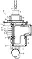
- FIGS. 1 is a top view of the brake control device 100
- FIG. 2 is a side view of the brake control device 100
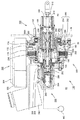
- FIG. 3 is a partial cross-sectional view for explaining the internal structure of the hydraulic control mechanism 150 of the brake control device.
- the motor control unit 300 has fins for heat dissipation formed on the outer surface. However, in FIG. 3, the fins are not shown in order to avoid complexity.
- the brake control device 100 includes a hydraulic control mechanism 150 that generates hydraulic pressure for performing brake control based on an operation amount of a brake pedal, a motor control unit 300 for controlling a motor, and a reservoir 700 that stores hydraulic oil. And.
- the hydraulic control mechanism 150 is fixed to a partition wall W that partitions the engine room R1 and the vehicle compartment R2 by bolts 152 shown in FIG.
- the motor is housed in the housing 160 of the hydraulic control mechanism 150.
- the hydraulic control mechanism 150 has a master cylinder 250 and a reservoir 700 on one side in the rod axis direction.
- the reservoir 700 is provided on the upper side of the master cylinder 250 in order to prevent air from entering the inside of the hydraulic oil and to make it easier to remove air already contained in the hydraulic oil.
- the space occupied by the entire brake control device 100 can be reduced.
- a motor control unit 300 is arranged on the same side as the reservoir 700 with respect to the hydraulic control mechanism 150, that is, on the upper side in this embodiment. With such an arrangement, the space occupied by the entire brake control device 100 can be reduced.
- the housing 160 of the hydraulic control mechanism 150 is fixed to the partition wall W, and the reservoir 700, the motor control unit 300, and the master cylinder 250 are fixed to the housing 160, whereby the master cylinder 250, the reservoir 700, The motor control unit 300 is fixed to the vehicle body. With such a structure, attachment to the vehicle body is simplified. Furthermore, it becomes possible to manufacture the motor control unit 300 in a separate process and then fix the motor control unit 300 to the housing 160, thereby improving productivity and reliability.
- the hydraulic control mechanism 150 includes a master cylinder 250 and a moving mechanism 200 having the cylindrical housing 160, and the housing 160 is provided with an internal motor and a piston, which will be described later.
- An opening is formed, and the housing 160 is provided with a cover 162 for closing the opening.
- a stepped wall 164 is provided on the master cylinder 250 side of the housing 160, and the master cylinder 250 is fixed to the wall 164 of the housing 160 by a bolt 166.
- the opening is formed on the other end side of the housing 160, and the cover 162 for closing the opening is provided.
- the cover 162 has a rod cover 168 that extends in the direction of the rod axis, which will be described later, and the rod cover 168 protrudes into the vehicle compartment R2 through an opening formed in the partition wall W.
- the rod cover 168 has a cylindrical shape for improving productivity and reliability, and an input rod 180 that moves in the axial direction of the rod cover 168 moves inside the rod cover 168 based on the operation of the brake pedal. It is extended.
- the housing 160 is fixed to the vehicle body by fixing the cover 162 to the partition wall W shown in FIG.
- the motor control unit 300 and the master cylinder 250 are fixed to the housing 160 of the moving mechanism 200 fixed to the vehicle body, the master cylinder 250, the reservoir 700, and the motor control unit 300 are produced individually. Alternatively, it can be assembled and then fixed to the housing 160, so that productivity can be improved. In particular, since the motor control unit 300 can be assembled on the production line for electronic components and then fixed to the hydraulic control mechanism 150, the reliability is improved in addition to the improvement in productivity.
- this assembly can be fixed to the housing 160 of the hydraulic control mechanism 150, so that the hydraulic oil passage between the reservoir 700 and the master cylinder 250 is connected.
- the master cylinder 250 can be fixed to the housing 160 after that, for example, after checking for leakage of hydraulic oil or the like, if necessary. With such a structure, productivity can be improved and reliability can be improved.
- the motor control unit 300 has a metallic case 302, and a control circuit having an inverter circuit for controlling a motor provided in the moving mechanism 200 is accommodated in the case 302. Has been.
- the motor control unit 300 converts DC power into AC power, and the AC power is supplied to a motor stator 174 housed in the housing 160 of the hydraulic control mechanism 150 to drive the motor.
- the case 302 of the motor control unit 300 is provided with a metallic lid 304, and a plurality of fins 312 for cooling are formed on the lower portion and outer periphery of the case 302.
- the fins 312 are shown in FIGS. 1 and 2, but the fins 312 are omitted in FIG. 3 to avoid complexity.
- a connector 306 for receiving DC power from a power source, a control command from a vehicle control device, and a status signal from a sensor is provided on the side of the motor control unit 300.
- the connector 306 is also connected with a communication line for transmitting / receiving information to / from other devices.
- the motor control unit 300 is arranged in a direction that crosses the axis of the input rod 180 of the hydraulic control mechanism 150 and is biased downward in the drawing. In other words, it is arranged to be biased toward the discharge port of the hydraulic oil of the master cylinder described later, and this bias creates a space on the connector 306 side of the motor control unit 300. Due to this arrangement, the connector 306 can be easily attached and detached. Further, even if various devices are present in the surroundings, a work space for attaching and detaching the connector 306 is secured, and the influence of other devices is reduced.
- the case 302 of the motor control unit 300 has a long shape, and a sufficient storage capacity can be secured even if the length in the direction crossing the axis of the input piston is shortened. Furthermore, a heat radiation area for heat generated inside can be secured.
- the axial direction of the input piston of the motor control unit 300 is a direction along the space required by the hydraulic control mechanism 150, and the length in the axial direction is used to secure a storage volume and a heat radiation area. Thus, an increase in the overall volume of the brake control device can be suppressed, and the influence on other devices can be reduced.
- a holding base 170 is formed on the reservoir 700 side of the housing 160 of the hydraulic control mechanism 150, and the case 302 of the motor control unit 300 is fixed to the holding base 170.
- Grease for improving heat conduction is applied between the holding table 170 and the case 302. In addition, you may provide the heat conductive sheet excellent in heat conduction.
- the motor control unit 300 is held biased toward the partition wall W (see FIG. 3).
- the partition wall side surface of the motor control unit 300 is located at substantially the same position as the end surface of the housing 160 of the moving mechanism 200, and the opposite surface is the master cylinder. It is located at substantially the same position as the end of 250.
- the case 302 of the motor control unit 300 has a shape that is long in the axial direction of the input piston of the hydraulic control mechanism 150, so that a large heat radiation area can be secured and the motor control unit 300 is sufficiently cooled.
- a space is formed between the master cylinder 250 and the case 302 of the motor control unit 300.
- the heat generated in the motor control unit 300 can be cooled by the wind flowing through the space.
- the fins are preferably formed side by side in the axial direction.
- the motor control unit 300 there is provided a switching semiconductor element that converts direct-current power, which will be described later, into alternating-current power, and generates heat with the power conversion.
- the generated heat is transmitted from the case 302 to the housing 160 of the moving mechanism 200 via the holding base 170 and cooled.
- the fins 312 are formed in the case 302 of the motor control unit 300 as described above, and cooling is performed by radiating heat through the fins 312. With such a structure, the cooling efficiency is improved, and the reliability can be improved by being able to sufficiently cool.
- a reservoir 700 is provided in a space between the case 302 of the motor control unit 300 and the master cylinder 250, and a structure for supplying hydraulic oil from the reservoir 700 to the master cylinder 250 is provided.
- the space between the case 302 and the master cylinder 250 of the motor control unit 300 is used as a space for forming the reservoir and forming a hydraulic oil supply path from the reservoir 700 to the master cylinder 250, The use efficiency of the space is improved, and the increase in size of the brake control device 100 is suppressed.
- the brake control device 100 acts as a booster.
- the input rod side of the hydraulic control mechanism 150 protrudes from the opening of the partition wall W into the vehicle interior, and is mechanically connected to a brake pedal (not shown).
- the input rod 180 is a master cylinder based on the depression amount of the brake pedal. Move to the side. Based on the movement of the input rod 180, the input piston 182 moves to the master cylinder side.
- the master cylinder 250 has a housing 260 in which a cylindrical hole is formed. Two pressure chambers 262 and 264 are formed in the hole.
- a free piston 266 is provided between the two pressure chambers 262 and 264, a pressure chamber 262 is formed on the other side of the free piston 266, and a pressure chamber 264 is formed on one side of the free piston 266. .
- the free piston 266 basically moves so that the pressures in the pressure chamber 262 and the pressure chamber 264 become substantially the same pressure. Since the hydraulic oil in the pressure chamber 262 is supplied from the discharge port 252 (FIG. 1) and the hydraulic oil in the pressure chamber 264 is supplied from the discharge port 254 (FIG. 1), the discharge port 252 and the discharge port 254 have substantially the same pressure. Of hydraulic oil is supplied.
- the pressure in the pressure chamber 262 increases based on the movement of the input piston 182.
- the free piston 266 moves toward the pressure chamber 264, and the pressure of the hydraulic oil in the pressure chamber 264 increases in the same manner.
- the hydraulic oil with the increased pressure is sent from the discharge ports 252 and 254 to the hydraulic pressure control device, and is sent from the hydraulic pressure control device to generate a braking force on a wheel cylinder WC of a brake provided on each wheel of the vehicle. . Since it is difficult to generate sufficient hydraulic oil pressure only with the operation force of the brake pedal, in the embodiment shown in FIG. 3, a control piston 190 is provided to control the movement of the control piston 190.
- a motor and a linear motion mechanism are provided.
- the motor has a stator 290 and a rotor 296, and the rotor 296 is rotated by a bearing 298 A held by the cover 162 of the moving mechanism 200 and a bearing 298 B held by the housing 160 of the moving mechanism 200. It is supported freely.
- the stator 290 has a stator core 292 and a stator winding 294 wound around the stator core 292.
- the rotor has a permanent magnet facing the stator core 292, and the permanent magnet forms a magnetic pole of the rotor 296.
- the position of the magnetic pole of the rotor 296 is detected by a resolver 280 and sent to the motor control unit 300, and the motor control unit 300 generates AC power based on the magnetic pole position of the rotor 296, and the stator winding 294 Supplied via power bus bar 172.
- the resolver 280 includes a resolver rotor 284 that is provided on the rotor 296 and rotates together with the rotor 296, and a resolver stator 282 that detects the rotational position of the resolver rotor 284, and the magnetic poles of the rotor 296.
- a signal representing the position of the motor is output from the resolver stator 282 to the motor control unit 300 via a signal line 174.
- the rotor 296 of the motor has a hollow shape, and a moving mechanism 200 that changes the torque of the motor into an axial force is provided inside the rotor 296, and the control piston 190 has a shaft based on the torque generated by the motor. Move in the direction.
- the moving mechanism 200 has a nut member 202 fixed to a hollow rotor 296, a ball 204, and a screw member 206.
- the motor rotor 296 rotates, the nut member 202 rotates.
- a hollow screw member 206 engaged with the ball 204 moves in the axial direction according to the rotation direction of the nut member 202.
- the input piston 182 moves in the direction of the master cylinder 250 by the brake operation. Due to the movement of the input piston 182, a difference in the positional relationship between the input piston 182 and the control piston 190 occurs.
- the motor is controlled so as to eliminate this movement difference, the nut member 202 is rotated by the torque of the motor, and the screw member 206 engaged with the nut member 202 moves to the master cylinder side along the axial direction.
- the force of both the input piston 182 and the control piston 190 is applied to the hydraulic oil in the pressure chamber 262 of the master cylinder, the pressure of the hydraulic oil in the pressure chamber 262 increases, and the action of the hydraulic oil in the pressure chamber 264 is caused by the action of the free piston 266.
- the pressure increases as well.
- a braking force of the brake is generated based on the hydraulic pressure in the pressure chambers 262 and 264.
- the pressure chambers 262 and 264 are respectively provided with return springs that always urge in the backward direction.
- the force acting on the hydraulic oil pressure is based on the pressure receiving area perpendicular to the axis, so that the area perpendicular to the axis of the input piston 182
- the hydraulic oil pressure can be increased with a force many times larger than the force pushing the input piston 182, and a large braking force can be generated.
- the control piston 190 is moved in the direction of the master cylinder at a speed faster than the moving speed of the input piston 182, it is possible to generate a large braking force for a small operation amount.
- control piston 190 when the control piston 190 is moved slowly or in the opposite direction with respect to the moving speed of the input piston 182, it is possible to suppress the generation of the braking force to the amount of movement of the input piston 182.
- a braking force is generated by the vehicle travel motor.
- the control piston 190 since the braking force based on the pressure of the hydraulic oil may be small or unnecessary, the control piston 190 is moved slowly as compared with the movement of the input piston 182 or moved in the direction opposite to the movement of the input piston 182. It will be.
- the input piston 182 When the brake pedal is not depressed, that is, when the brake is not operated, the input piston 182 is in the non-operating position, and the control piston 190 for controlling the hydraulic oil pressure of the master cylinder 250 is in the non-operating state. In position. Since the control piston 190 and the input piston 182 are in an inoperative position, the free piston 266 is in an inoperative position. Since the control piston 190 and the free piston 266 are on the brake pedal side, which is the non-operating position as described above, the relief ports 256 and 258 of the pressure chambers 262 and 264 are opened, and the pressure chambers 262 and 264 are opened to the relief port.
- the pressure chambers 262 and 264 are filled with the hydraulic oil of the reservoir 3 in communication with the reservoir 3 through 256 and 258.
- the passage connecting the pressure chambers 262 and 264 and the relief ports 256 and 258 is blocked by the control piston 190 and the free piston 266.
- the pressure of the hydraulic oil in the pressure chamber 262 increases in accordance with the movement of the input piston 182 and the control piston 190, and accordingly, the free piston 266 moves to the master cylinder side, and the hydraulic oil in the pressure chamber 264 The pressure increases.
- a braking force is generated based on this pressure.
- a pair of springs are provided between the input piston 182 and the control piston 190, and the relative positional relationship between the input piston 182 and the control piston 190 is maintained at the neutral position when the brake is not operated.
- the motor control unit 300 is fixed to a holding base 170 provided in the housing 160 of the moving mechanism 200.
- the power board 352 is fixed to the case 302 of the motor control unit 300.
- the case 302 is made of metal and has a bottom, and an upper side thereof is opened for assembling electric components.
- a fixing member 301A for fixing the case 302 to the housing 160 of the moving mechanism 200 is provided on the outer periphery of the lower portion of the case 302. To 301D are provided. In this embodiment, since the screws are fixed, the fixing members 301A to 301D are feet having screw holes.
- Fins 312 for heat dissipation are formed on part of the outer peripheral surface and bottom surface of the case 302 of the motor control unit 300.
- a hole 314 is formed in the bottom of the case 302 to send AC power to the motor and to receive an output signal from a resolver 280 attached inside the housing 160.
- a hole for attaching a connector for transferring DC power and signals is provided on the side surface of the case 302.
- the power board 352 is disposed so as to sandwich the heat dissipating grease in the lower part inside the case 302, and the power board 352 is fixed to the bottom surface of the case 302 with screws.
- semiconductor elements 350A and 350B constituting an inverter circuit for converting DC power into AC power are mounted on the power board 352.
- the semiconductor element 350A is a power switching semiconductor that operates as upper arms of the U phase, V phase, and W phase of the inverter circuit
- the semiconductor element 350B is a power switching that operates as lower arms of the U phase, V phase, and W phase of the inverter circuit. It is a semiconductor.
- the number of semiconductor elements constituting the upper and lower arms of the inverter is six.
- each of the arms may be composed of a power switching semiconductor in which the arms are connected in parallel.
- the inverter circuit is configured with the power switching semiconductor.
- the power board 352 is provided with DC terminals 358A and 358B for receiving DC power. Moreover, it has U-phase, V-phase, and W-phase AC terminals 356U, 356V, and 356W for outputting AC power generated from the DC power.
- the power board 352 is provided with a lead frame 320 for supplying a drive signal from a control board described later to the semiconductor elements 350A and 350B constituting the inverter circuit. By applying the drive signal to the semiconductor elements 350A and 350B of each arm, each semiconductor element performs a switching operation and converts DC power into AC power.
- the lead frame 320 functions not only to transmit the drive signal but also to connect signal lines between the substrates.
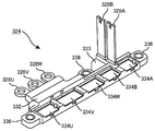
- a power terminal member 324 for transmitting and receiving direct current and alternating current power is attached to the case 302 of the motor control unit 300 to which the power board 352 shown in FIG. 4 is attached. Details of the structure of the power terminal member 324 are shown in FIG.
- the power terminal member 324 includes DC input terminals 328A and 328B for receiving DC power from a smoothing capacitor, which will be described later, DC output terminals 334A and 334B for outputting the input DC input to the power board 352, and the power board 352.
- the power terminal member 324 has a structure in which a conductor is embedded in resin.
- the power terminal member 324 has a resin output port 332 for holding the AC input terminals 334U, 334V, and 334W, and a resin product for holding the DC input terminal 328. And an input port 333.
- the power terminal member 324 is fixed to the bottom surface of the case 302, and then the DC output terminals 334A and 334B of the power terminal member 324 are connected to the DC terminals 358A and 358B of the power board 352 by wire bonding 330, respectively.
- the AC terminals 356U, 356V, and 356W of the power board 352 are connected to the AC input terminals 334U, 334V, and 334W of the power terminal member 324 by wire bonding 330, respectively.
- a connector 306 for connecting to the outside and receiving power and signals is fixed to the side opening of the case 302.
- the connector 306 has a power terminal 308 for receiving DC power and a signal terminal 307 for transmitting and receiving signals.
- the signal includes a local network communication signal for receiving a control command and transmitting status information, and a signal for receiving status information from a sensor.
- the electric connection between the power board 352 and the power terminal member 324 is performed by the wire bonding 330, but the connection may be performed by welding using a bus bar.
- AC output terminals 326U, 326V, and 326W for supplying AC power to the motor are provided on the passenger compartment side, and AC terminals 356U, 356V, and 356W are disposed on the passenger compartment side of the power board 352, Electrical components are arranged efficiently. Also, AC power wiring is shortened. In this embodiment, the use of the power terminal member 324 has an effect of reducing the space for wiring. Since the motor control unit 300 and the motor are connected via the hole 314, the influence of noise is small and the influence of external dirt is low, for example, the influence of anti-freezing material on the road is difficult.
- AC output terminals 326U, 326V, and 326W are provided on the passenger compartment side, and the connector 306 is attached to the side surface in the direction along the input piston axis of the hydraulic control mechanism 150. Therefore, the power terminal 308 of the connector 306 is connected to the power board 352. It can be located on the power terminal side, the electrical wiring relationship becomes easy, and the motor control unit 300 is reduced in size. Further, since the lead frame 320 is used, connection is facilitated.
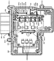
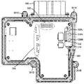
- a power supply board 360 is attached as shown in FIG.
- a noise filter component 366 for removing noise including a smoothing capacitor 362 and a noise filter capacitor 364 is attached to the power supply substrate 360.
- a DC bus bar for transmitting DC power is attached, and a relay 370 for protection is attached.
- the DC bus bar of the power supply board 360 is connected to the power terminal 308 of the connector 306 by welding, and a relay 370 and a capacitor 362 are connected to the DC bus bar.
- the power supply board 360 has an opening 361, and the lead frame 320 is connected to the control board thereon through the opening 361.
- the capacitor 362 and the relay 370 are arranged side by side, and the outer surface thereof is held by the power supply board 360. While the vehicle is always running, vibration is applied to the motor control unit 300. However, since the outer surface of the capacitor 362 and the relay 370 is held by the power supply board 360, the effect of reducing stress due to vibration on the terminals can be reduced. Yes, life is extended and reliability is improved. Also, the height is suppressed, and the dimension of the motor control unit 300 in the height direction is suppressed.
- FIG. 8 shows a state in which the control board 380 is attached after the assembly process of FIG.
- a control circuit including a computer is attached to the control board 380, and a control signal for driving the inverter is also generated by this board.
- the signal terminals 307 of the connector 306 are provided with vertical connection pins, which are connected to the connectors by the connection portions 382 of the control board 380, and further connected to the lead frame 320.
- the terminals are connected by solder at the signal line connecting portion 384.
- notches are provided at positions facing the AC output terminals 326U, 326V, 326W, and the AC output terminals 326U, 326V, 326W can be screwed.
- control board 380 and another board, for example, the power board 352 are connected by the lead frame 320, wiring is easy and productivity is improved. Furthermore, wiring troubles are reduced and reliability is improved. Further, since the control board 380 and the connector 306 are connected to the connection pin connected to the connector by the connection portion 382, the productivity is also improved in this respect.
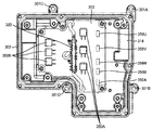
- FIG. 9 is a view of the motor control unit 300 as viewed from the back side.
- a hole 314 for supplying AC power to the motor is formed in the back surface 302A of the metal case 302.
- fins 312A, 312B, 312C and 312D for cooling are formed on the back surface 302A of the case 302.
- the holes 301A to 301D are holes for fixing the motor control unit 300 to the housing 160 with screws.
- the filter 310 is a filter that removes dust from the air that the motor control unit 300 breathes.
- the fin 312 ⁇ / b> A and the fin 312 ⁇ / b> B have a function of creating an air flow in the direction along the rod axis of the hydraulic control mechanism 150 in the space between the master cylinder 250 in addition to the cooling function. Is in the direction along the axis of the input piston of the hydraulic control mechanism 150.
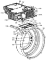
- FIGS. 10 and 11 are diagrams illustrating a process of fixing the case 302 of the motor control unit 300 to the housing 160.
- FIG. Originally, the piston 160 and the moving mechanism 200 are already attached to the housing 160, and further the master cylinder 250 is attached. In order to help understanding the mounting structure between the case 302 and the housing 160, the piston and the moving mechanism 200 are used.
- the master cylinder 250 is illustrated as being removed in FIGS. 10 and 11.
- the housing 160 is provided with a holding base 170 for supporting the case 302 of the motor control unit 300.
- An opening 171 is formed in the holding base 170, and an AC terminal holding member 176 made of resin is provided inside the opening 171.
- a three-phase AC bus bar 172 is embedded in the AC terminal holding member 176, and AC terminals 175U, 175V, and 175W which are one side terminals of the bus bar 172 are disposed on the upper surface.
- the other side of the bus bar 172 is connected to the stator winding of the motor.
- a signal line support member 178 for supporting the signal line along with the AC terminal holding member 176 is provided.
- the fixing members 301A, 301B, 301C, and 301D of the case 302 are fixed to the fixing portions 170A, 170B, 170C, and 170D of the holding base 170 with screws.
- the AC output terminals 326U, 326V, and 326W shown in FIG. 8 are fixed to the AC terminals 175U, 175V, and 175W of the holding base 170, respectively.
- a signal line for receiving a resolver signal is also connected.
- the main components of the motor control unit 300 can be assembled on the electronic component manufacturing line, and the assembled motor control unit 300 can be attached to the housing 160 of the moving mechanism 200, thereby improving productivity.
- the main parts can be assembled in advance on another production line, the reliability is improved.
Abstract
Description
本発明の他の目的、特徴及び利点は添付図面に関する以下の本発明の実施例の記載から明らかになるであろう。 According to the present invention, an increase in the size of the brake control device can be suppressed.
Other objects, features and advantages of the present invention will become apparent from the following description of embodiments of the present invention with reference to the accompanying drawings.
モータ制御ユニットのケースは入力ピストンの軸線方向に長い形状を為しており、油圧を制御する機構が必要とする空間に合わせた形状となっている。このためブレーキ制御装置の体積の増大が抑えられる。 [Suppression of enlargement]
The case of the motor control unit has a shape that is long in the axial direction of the input piston, and has a shape that matches the space required by the mechanism that controls the hydraulic pressure. For this reason, an increase in the volume of the brake control device can be suppressed.
ブレーキ制御装置は油圧を制御する機構とモータ制御ユニットとを有し、前記油圧を制御する機構は、一方側に配置されたマスタシリンダと、他方側に配置された入力ピストンと制御ピストンと前記制御ピストンを移動させるための移動機構とを有し、前記モータ制御ユニットは冷却のための金属ケースを有し、前記金属ケースは、その一方側の端部が前記マスタシリンダの端部とほぼ同じ位置に位置し、他方側の端部が前記移動機構の端部とほぼ同じ位置に位置するように、油圧を制御する機構の入力ピストン軸線方向に長い形状を有している。さらにフィンが前記ケースの外側に形成されている。油圧を制御する機構の入力ピストン軸線方向の長さを利用して冷却フィンを形成しているので大きな冷却面積が確保でき、冷却効果が向上する。 [Improvement of cooling effect]
The brake control device has a mechanism for controlling oil pressure and a motor control unit. The mechanism for controlling oil pressure includes a master cylinder disposed on one side, an input piston, a control piston disposed on the other side, and the control. A moving mechanism for moving the piston, and the motor control unit has a metal case for cooling, and the end of one side of the metal case is substantially the same as the end of the master cylinder. It has a long shape in the direction of the input piston axis of the mechanism for controlling the hydraulic pressure so that the other end is located at substantially the same position as the end of the moving mechanism. Further, fins are formed outside the case. Since the cooling fin is formed by using the length of the input piston axial direction of the mechanism for controlling the hydraulic pressure, a large cooling area can be secured and the cooling effect is improved.
モータの出力に基づいて制御ピストンを移動する移動体のハウジングを車体に固定し、前記ハウジングにマスタシリンダやモータ制御ユニットを固定している。このため、重要部品が組込まれたモータ制御ユニットを前記ハウジングに固定することが可能となり、生産性が向上する。 [Improve productivity]
A housing of a moving body that moves the control piston based on the output of the motor is fixed to the vehicle body, and a master cylinder and a motor control unit are fixed to the housing. For this reason, it becomes possible to fix the motor control unit in which the important parts are incorporated to the housing, and the productivity is improved.
マスタシリンダとモータ制御ユニットの金属ケースとの間に形成された空間に、リザーバとマスタシリンダとを繋ぐ油路が形成されているので、前記油路は機械的な損傷を受けにくくなっている。マスタシリンダとモータ制御ユニットはエンジンルームに置かれる可能性が非常に高い。エンジンの点検や修理において、工具が触れる可能性があるが、マスタシリンダと金属ケースとの間に形成された空間は工具などが触れる可能性が非常に低く、前記油路が損傷を受ける可能性が極めて低い。 [Improvement of reliability]
Since an oil passage that connects the reservoir and the master cylinder is formed in a space formed between the master cylinder and the metal case of the motor control unit, the oil passage is less susceptible to mechanical damage. The master cylinder and motor control unit are very likely to be placed in the engine room. There is a possibility that tools may touch during inspection and repair of the engine, but the space formed between the master cylinder and the metal case is very unlikely to be touched by tools, and the oil passage may be damaged. Is extremely low.
図1~図3に示される如く、モータ制御ユニット300は移動機構200のハウジング160に設けられた保持台170に固定されている。次に図4~図11を参照して、モータ制御ユニット300の構造および製造方法について説明する。図4に示されるように、モータ制御ユニット300のケース302にパワー基板352を固定する。ケース302は金属製で底を有し、その上側は電気部品の組立てのために開口し、ケース302の低部外周にはこのケース302を移動機構200のハウジング160に固定するための固定部材301A~301Dが設けられている。この実施例では、ねじで固定しているので、固定部材301A~301Dはねじ穴を有する足である。 [Assembly of motor control unit 300]
As shown in FIGS. 1 to 3, the
上記記載は実施例についてなされたが、本発明はそれに限らず、本発明の精神と添付の請求の範囲の範囲内で種々の変更および修正をすることができることは当業者に明らかである。 The fixing
While the above description has been made with reference to exemplary embodiments, it will be apparent to those skilled in the art that the invention is not limited thereto and that various changes and modifications can be made within the spirit of the invention and the scope of the appended claims.
150 油圧制御機構
160 ハウジング
170 保持台
180 入力ロッド
182 入力ピストン
190 制御ピストン
200 移動機構
250 マスタシリンダ
290 固定子
296 回転子
300 モータ制御ユニット
352 パワー基板
360 電源基板
380 制御基板
700 リザーバ DESCRIPTION OF
Claims (11)
- ブレーキ操作によって移動する入力ピストン(182)と制御ピストン(190)とに基づき作動油の油圧を発生するマスタシリンダ(250)と、モータ(290,296)と、前記モータの回転に伴い前記制御ピストンを移動する移動機構(200)とを有する油圧制御機構(150)と、
前記モータの回転を制御するモータ制御ユニット(300)と、を有したブレーキ制御装置(100)において、
前記モータ制御ユニット(300)は制御回路を内蔵する金属製ケース(302)を有し、前記金属製ケース(302)は前記移動機構(200)のハウジング(160)に固定され、前記入力ピストン(182)の軸線方向において、前記ケース(302)の一方の端部が前記移動機構(200)の端部とほぼ同じ位置に位置し、前記ケース(302)の他端部が前記マスタシリンダ(250)の端部とほぼ同じ位置に位置することを特徴とするブレーキ制御装置。 A master cylinder (250) that generates hydraulic oil pressure based on an input piston (182) and a control piston (190) that are moved by a brake operation, a motor (290, 296), and the control piston as the motor rotates. A hydraulic control mechanism (150) having a moving mechanism (200) for moving
A brake control device (100) having a motor control unit (300) for controlling rotation of the motor;
The motor control unit (300) has a metal case (302) containing a control circuit, and the metal case (302) is fixed to a housing (160) of the moving mechanism (200), and the input piston ( 182) in the axial direction, one end of the case (302) is located at substantially the same position as the end of the moving mechanism (200), and the other end of the case (302) is the master cylinder (250). The brake control device is located at substantially the same position as the end portion of). - 前記モータ制御ユニット(300)は交流電力を出力するための交流出力端子(326U,326V,326W)と前記交流電力を発生させるための半導体素子(350A,350B)とを有し、前記入力ピストン(182)の移動方向において、前記移動機構(200)の側に前記交流出力端子(326U,326V,326W)が配置され、前記マスタシリンダ(250)の側に前記半導体素子(350A,350B)が配置されていることを特徴とする、請求項1に記載のブレーキ制御装置。 The motor control unit (300) includes an AC output terminal (326U, 326V, 326W) for outputting AC power and a semiconductor element (350A, 350B) for generating the AC power, and the input piston ( 182) in the moving direction, the AC output terminals (326U, 326V, 326W) are disposed on the moving mechanism (200) side, and the semiconductor elements (350A, 350B) are disposed on the master cylinder (250) side. The brake control device according to claim 1, wherein the brake control device is provided.
- 前記モータ制御ユニット(300)が、前記移動機構(200)側に配置された、交流電力を発生させるための半導体素子(350A,350B)を含むパワー基板(352)と、該パワー基板の上に配置された、リレー(370)を有する電源基板(360)と、該電源基板の上に配置された制御基板(380)とを有することを特徴とする、請求項1に記載のブレーキ制御装置。 The motor control unit (300) is disposed on the moving mechanism (200) side and includes a power substrate (352) including semiconductor elements (350A, 350B) for generating AC power, and on the power substrate The brake control device according to claim 1, characterized in that it has a power supply board (360) having a relay (370) and a control board (380) arranged on the power supply board.
- 圧力室(262,264)を有するマスタシリンダ(250)と、ブレーキ操作に基づいて軸方向に移動することにより前記圧力室の体積を変化させる入力ピストン(182)と、軸方向に移動することにより前記圧力室の体積を変化させる制御ピストン(190)と、前記制御ピストンを移動させるための回転トルクを発生するモータ(290,296)と、前記モータの回転に基づいて前記制御ピストンを軸方向に移動する移動機構(200)と、前記モータの回転トルクを制御するモータ制御ユニット(300)と、前記圧力室に満たされる作動油を蓄えるリザーバ(700)とを有したブレーキ制御装置(100)において、
前記モータ制御ユニット(300)は制御回路を内蔵する金属製ケース(302)を有し、前記金属製ケース(302)は前記移動機構(200)の外面に固定され、前記入力ピストン(182)の軸線方向において、前記ケース(302)の一端が前記制御ピストンを移動させるための前記移動機構(200)の端部とほぼ同じ位置に位置し、前記ケース(302)の他端が前記マスタシリンダ(250)の端部とほぼ同じ位置に位置し、
前記ケース(302)と前記マスタシリンダ(250)との間に空間が形成され、前記マスタシリンダの前記空間側に前記リザーバ(700)からの作動油を供給するための油路(256,258)が設けられていることを特徴とするブレーキ制御装置。 A master cylinder (250) having pressure chambers (262, 264), an input piston (182) for changing the volume of the pressure chamber by moving in the axial direction based on a brake operation, and by moving in the axial direction A control piston (190) for changing the volume of the pressure chamber, motors (290, 296) for generating rotational torque for moving the control piston, and the control piston in the axial direction based on the rotation of the motor In a brake control device (100) having a moving mechanism (200) that moves, a motor control unit (300) that controls rotational torque of the motor, and a reservoir (700) that stores hydraulic oil filled in the pressure chamber. ,
The motor control unit (300) has a metal case (302) containing a control circuit, and the metal case (302) is fixed to the outer surface of the moving mechanism (200), and the input piston (182) In the axial direction, one end of the case (302) is positioned substantially at the same position as the end of the moving mechanism (200) for moving the control piston, and the other end of the case (302) is the master cylinder ( 250) at substantially the same position as the end,
A space is formed between the case (302) and the master cylinder (250), and oil passages (256, 258) for supplying hydraulic oil from the reservoir (700) to the space side of the master cylinder. A brake control device comprising: - 前記リザーバ(700)の一部が前記ケース(302)と前記マスタシリンダ(250)との間に形成された前記空間に配置されていることを特徴とする、請求項4に記載のブレーキ制御装置。 The brake control device according to claim 4, wherein a part of the reservoir (700) is disposed in the space formed between the case (302) and the master cylinder (250). .
- 前記モータ制御ユニット(300)は交流電力を出力するための交流出力端子(326U,326V,326W)と前記交流電力を発生させるための半導体素子(350A,350B)とを有し、前記入力ピストン(182)の移動方向において、前記移動機構(200)の側に前記交流出力端子(326U,326V,326W)が配置され、前記マスタシリンダ(250)の側に前記半導体素子(350A,350B)が配置されたことを特徴とする、請求項4に記載のブレーキ制御装置。 The motor control unit (300) includes an AC output terminal (326U, 326V, 326W) for outputting AC power and a semiconductor element (350A, 350B) for generating the AC power, and the input piston ( 182) in the moving direction, the AC output terminals (326U, 326V, 326W) are disposed on the moving mechanism (200) side, and the semiconductor elements (350A, 350B) are disposed on the master cylinder (250) side. The brake control device according to claim 4, wherein
- 前記モータ制御ユニット(300)が、前記移動機構(200)側に配置された、交流電力を発生させるための半導体素子(350A,350B)を含むパワー基板(352)と、該パワー基板の上に配置された、リレーを有する電源基板(360)と、該電源基板の上に配置された制御基板(380)とを有することを特徴とする、請求項4に記載のブレーキ制御装置。 The motor control unit (300) is disposed on the moving mechanism (200) side and includes a power substrate (352) including semiconductor elements (350A, 350B) for generating AC power, and on the power substrate The brake control device according to claim 4, characterized in that it has a power supply board (360) having a relay and a control board (380) arranged on the power supply board.
- 第1の圧力室(262)と、第2の圧力室(264)と、前記第1と第2の圧力室との間に設けられたフリーピストン(266)とを有するマスタシリンダ(250)と、ブレーキ操作に基づいて軸方向に移動することにより前記第1の圧力室の体積を変化させる入力ピストン(182)と、軸方向に移動することにより前記第1の圧力室の体積を変化させる制御ピストン(190)と、前記制御ピストンを移動させるための回転トルクを発生するモータ(290,296)と、前記モータの回転に基づいて前記制御ピストンを軸方向に移動する移動機構(200)と、前記モータの回転トルクを制御するモータ制御ユニット(300)と、前記圧力室に満たされる油を蓄えるリザーバ(700)とを有したブレーキ制御装置(100)において、
前記モータ制御ユニット(300)が前記移動機構(200)の外面に固定され、前記モータ(290,296)が前記移動機構(200)の内部に配置され、前記モータ制御ユニットのケース(302)と前記マスタシリンダ(250)との間に空間が形成され、前記ケース(302)の前記空間側の面に冷却のためのフィン(312)が形成されていることを特徴とするブレーキ制御装置。 A master cylinder (250) having a first pressure chamber (262), a second pressure chamber (264), and a free piston (266) provided between the first and second pressure chambers; An input piston (182) that changes the volume of the first pressure chamber by moving in the axial direction based on a brake operation, and a control that changes the volume of the first pressure chamber by moving in the axial direction A piston (190), motors (290, 296) for generating rotational torque for moving the control piston, a moving mechanism (200) for moving the control piston in the axial direction based on the rotation of the motor, A brake control device (100) having a motor control unit (300) for controlling the rotational torque of the motor and a reservoir (700) for storing oil filled in the pressure chamber. Te,
The motor control unit (300) is fixed to the outer surface of the moving mechanism (200), the motors (290, 296) are disposed inside the moving mechanism (200), and a case (302) of the motor control unit A brake control device, wherein a space is formed between the master cylinder (250) and fins (312) for cooling are formed on the space-side surface of the case (302). - 前記リザーバ(700)の一部が前記ケース(302)と前記マスタシリンダ(250)との間に形成された前記空間に配置されていることを特徴とする、請求項8に記載のブレーキ制御装置。 The brake control device according to claim 8, wherein a part of the reservoir (700) is disposed in the space formed between the case (302) and the master cylinder (250). .
- 前記モータ制御ユニット(300)は交流電力を出力するための交流出力端子(326U,326V,326W)と前記交流電力を発生させるための半導体素子(350A,350B)とを有し、前記入力ピストン(182)の移動方向において、前記移動機構(200)の側に前記交流出力端子(326U,326V,326W)が配置され、前記マスタシリンダ(250)の側に前記半導体素子(350A,350B)が配置されたことを特徴とする、請求項8に記載のブレーキ制御装置。 The motor control unit (300) includes an AC output terminal (326U, 326V, 326W) for outputting AC power and a semiconductor element (350A, 350B) for generating the AC power, and the input piston ( 182) in the moving direction, the AC output terminals (326U, 326V, 326W) are disposed on the moving mechanism (200) side, and the semiconductor elements (350A, 350B) are disposed on the master cylinder (250) side. The brake control device according to claim 8, wherein
- 前記モータ制御ユニット(300)が、前記移動機構(200)側に配置された、交流電力を発生させるための半導体素子(350A,350B)を含むパワー基板(352)と、該パワー基板の上に配置された、リレーを有する電源基板(360)と、該電源基板の上に配置された制御基板(380)とを有することを特徴とする、請求項8に記載のブレーキ制御装置。 The motor control unit (300) is disposed on the moving mechanism (200) side and includes a power substrate (352) including semiconductor elements (350A, 350B) for generating AC power, and on the power substrate 9. The brake control device according to claim 8, comprising a power supply board (360) having a relay and a control board (380) arranged on the power supply board.
Priority Applications (2)
| Application Number | Priority Date | Filing Date | Title |
|---|---|---|---|
| DE112009003622.8T DE112009003622B4 (en) | 2008-12-04 | 2009-11-30 | brake control device |
| US13/132,434 US8959908B2 (en) | 2008-12-04 | 2009-11-30 | Brake controller |
Applications Claiming Priority (2)
| Application Number | Priority Date | Filing Date | Title |
|---|---|---|---|
| JP2008309228A JP5216558B2 (en) | 2008-12-04 | 2008-12-04 | Control device for brake |
| JP2008-309228 | 2008-12-04 |
Publications (1)
| Publication Number | Publication Date |
|---|---|
| WO2010064593A1 true WO2010064593A1 (en) | 2010-06-10 |
Family
ID=42233242
Family Applications (1)
| Application Number | Title | Priority Date | Filing Date |
|---|---|---|---|
| PCT/JP2009/070093 WO2010064593A1 (en) | 2008-12-04 | 2009-11-30 | Brake controller |
Country Status (4)
| Country | Link |
|---|---|
| US (1) | US8959908B2 (en) |
| JP (1) | JP5216558B2 (en) |
| DE (1) | DE112009003622B4 (en) |
| WO (1) | WO2010064593A1 (en) |
Cited By (2)
| Publication number | Priority date | Publication date | Assignee | Title |
|---|---|---|---|---|
| CN103209873A (en) * | 2010-11-17 | 2013-07-17 | 本田技研工业株式会社 | Vehicle-body attachment structure for electric brake actuator |
| CN104057939A (en) * | 2013-03-21 | 2014-09-24 | 日立汽车系统株式会社 | Brake control apparatus |
Families Citing this family (10)
| Publication number | Priority date | Publication date | Assignee | Title |
|---|---|---|---|---|
| JP5321830B2 (en) * | 2009-08-03 | 2013-10-23 | 日立オートモティブシステムズ株式会社 | Booster, assembly jig and assembly method thereof |
| JP2012035814A (en) * | 2010-08-11 | 2012-02-23 | Hitachi Automotive Systems Ltd | Electric booster |
| JP6117577B2 (en) | 2013-03-15 | 2017-04-19 | 日立オートモティブシステムズ株式会社 | Electronic control unit |
| JP6165571B2 (en) | 2013-09-19 | 2017-07-19 | 日立オートモティブシステムズ株式会社 | Brake control device |
| JP6117661B2 (en) | 2013-09-19 | 2017-04-19 | 日立オートモティブシステムズ株式会社 | Electronic control unit |
| CN105774787A (en) * | 2014-12-25 | 2016-07-20 | 日立汽车系统株式会社 | Brake control device |
| JP6370243B2 (en) * | 2015-03-06 | 2018-08-08 | 日立オートモティブシステムズ株式会社 | Electronic circuit equipment |
| JP6627050B2 (en) * | 2015-03-31 | 2020-01-08 | ヴィオニア日信ブレーキシステムジャパン株式会社 | Brake control device |
| CN110290988B (en) * | 2017-02-23 | 2021-12-03 | 日立安斯泰莫株式会社 | Electric booster |
| DE102017211898A1 (en) * | 2017-07-12 | 2019-01-17 | Robert Bosch Gmbh | Pressure medium unit |
Citations (2)
| Publication number | Priority date | Publication date | Assignee | Title |
|---|---|---|---|---|
| JPH10257708A (en) * | 1997-03-10 | 1998-09-25 | Toshiba Fa Syst Eng Kk | Motor with built-in inverter |
| EP1997702A1 (en) * | 2007-05-31 | 2008-12-03 | Hitachi Ltd. | Electrically driven brake booster |
Family Cites Families (3)
| Publication number | Priority date | Publication date | Assignee | Title |
|---|---|---|---|---|
| JP4692837B2 (en) | 2005-06-30 | 2011-06-01 | 日立オートモティブシステムズ株式会社 | Electric booster |
| JP5024611B2 (en) * | 2007-06-05 | 2012-09-12 | 日立オートモティブシステムズ株式会社 | Electric booster and manufacturing method thereof |
| US8387381B2 (en) | 2008-01-31 | 2013-03-05 | Hitachi, Ltd. | Electric booster |
-
2008
- 2008-12-04 JP JP2008309228A patent/JP5216558B2/en active Active
-
2009
- 2009-11-30 WO PCT/JP2009/070093 patent/WO2010064593A1/en active Application Filing
- 2009-11-30 US US13/132,434 patent/US8959908B2/en active Active
- 2009-11-30 DE DE112009003622.8T patent/DE112009003622B4/en active Active
Patent Citations (2)
| Publication number | Priority date | Publication date | Assignee | Title |
|---|---|---|---|---|
| JPH10257708A (en) * | 1997-03-10 | 1998-09-25 | Toshiba Fa Syst Eng Kk | Motor with built-in inverter |
| EP1997702A1 (en) * | 2007-05-31 | 2008-12-03 | Hitachi Ltd. | Electrically driven brake booster |
Cited By (3)
| Publication number | Priority date | Publication date | Assignee | Title |
|---|---|---|---|---|
| CN103209873A (en) * | 2010-11-17 | 2013-07-17 | 本田技研工业株式会社 | Vehicle-body attachment structure for electric brake actuator |
| US9290170B2 (en) | 2010-11-17 | 2016-03-22 | Honda Motor Co., Ltd. | Vehicle-body attachment structure for electric brake actuator |
| CN104057939A (en) * | 2013-03-21 | 2014-09-24 | 日立汽车系统株式会社 | Brake control apparatus |
Also Published As
| Publication number | Publication date |
|---|---|
| JP5216558B2 (en) | 2013-06-19 |
| US8959908B2 (en) | 2015-02-24 |
| DE112009003622B4 (en) | 2022-12-01 |
| US20110259005A1 (en) | 2011-10-27 |
| DE112009003622T5 (en) | 2012-05-24 |
| JP2010132102A (en) | 2010-06-17 |
Similar Documents
| Publication | Publication Date | Title |
|---|---|---|
| WO2010064593A1 (en) | Brake controller | |
| JP5450042B2 (en) | Actuator control device | |
| JP5260347B2 (en) | Power converter | |
| JP7051698B2 (en) | Operating equipment for hydraulic operating systems | |
| US8002090B2 (en) | Electro-mechanical brake apparatus | |
| JP5147943B2 (en) | Electric power steering device and control device integrated motor | |
| EP2006987B1 (en) | Power converter device | |
| JP5244876B2 (en) | Power converter and electric vehicle | |
| JP5250297B2 (en) | Power converter | |
| JP4987495B2 (en) | Motor drive system for rail car drive | |
| JP2010132103A (en) | Brake control device | |
| CN110892614B (en) | Electric drive device and electric power steering device | |
| CN105827068A (en) | Rotating electrical machine | |
| US20140151146A1 (en) | Mold module utilized as power unit of electric power steering apparatus and electric power steering apparatus | |
| JP5284217B2 (en) | Electronic circuit device for vehicle | |
| JP2014131445A (en) | Integrated-inverter electric compressor | |
| JP2014143841A (en) | Inverter integrated motor | |
| JP2015089244A (en) | Inverter device for motor | |
| JP5622659B2 (en) | Power converter | |
| JP2014184740A (en) | Brake controller | |
| JP2006274921A (en) | Electric pump unit | |
| JP6042004B1 (en) | High voltage unit used in inverter device and inverter device using the same | |
| JP2011031856A (en) | Brake control device | |
| CN106165280A (en) | Mold module | |
| WO2021192380A1 (en) | Power conversion device and mechatronic power conversion device |
Legal Events
| Date | Code | Title | Description |
|---|---|---|---|
| 121 | Ep: the epo has been informed by wipo that ep was designated in this application |
Ref document number: 09830359 Country of ref document: EP Kind code of ref document: A1 |
|
| WWE | Wipo information: entry into national phase |
Ref document number: 1120090036228 Country of ref document: DE Ref document number: 112009003622 Country of ref document: DE |
|
| WWE | Wipo information: entry into national phase |
Ref document number: 13132434 Country of ref document: US |
|
| 122 | Ep: pct application non-entry in european phase |
Ref document number: 09830359 Country of ref document: EP Kind code of ref document: A1 |