WO2010064491A1 - 太陽光発電モジュール用保護シート、保護シートの製造方法及び太陽光発電モジュール保護方法 - Google Patents
太陽光発電モジュール用保護シート、保護シートの製造方法及び太陽光発電モジュール保護方法 Download PDFInfo
- Publication number
- WO2010064491A1 WO2010064491A1 PCT/JP2009/067753 JP2009067753W WO2010064491A1 WO 2010064491 A1 WO2010064491 A1 WO 2010064491A1 JP 2009067753 W JP2009067753 W JP 2009067753W WO 2010064491 A1 WO2010064491 A1 WO 2010064491A1
- Authority
- WO
- WIPO (PCT)
- Prior art keywords
- clay
- protective sheet
- film layer
- power generation
- generation module
- Prior art date
- Legal status (The legal status is an assumption and is not a legal conclusion. Google has not performed a legal analysis and makes no representation as to the accuracy of the status listed.)
- Ceased
Links
Classifications
-
- B—PERFORMING OPERATIONS; TRANSPORTING
- B32—LAYERED PRODUCTS
- B32B—LAYERED PRODUCTS, i.e. PRODUCTS BUILT-UP OF STRATA OF FLAT OR NON-FLAT, e.g. CELLULAR OR HONEYCOMB, FORM
- B32B27/00—Layered products comprising a layer of synthetic resin
- B32B27/32—Layered products comprising a layer of synthetic resin comprising polyolefins
- B32B27/322—Layered products comprising a layer of synthetic resin comprising polyolefins comprising halogenated polyolefins, e.g. PTFE
-
- B—PERFORMING OPERATIONS; TRANSPORTING
- B32—LAYERED PRODUCTS
- B32B—LAYERED PRODUCTS, i.e. PRODUCTS BUILT-UP OF STRATA OF FLAT OR NON-FLAT, e.g. CELLULAR OR HONEYCOMB, FORM
- B32B9/00—Layered products comprising a layer of a particular substance not covered by groups B32B11/00 - B32B29/00
- B32B9/002—Layered products comprising a layer of a particular substance not covered by groups B32B11/00 - B32B29/00 comprising natural stone or artificial stone
-
- B—PERFORMING OPERATIONS; TRANSPORTING
- B32—LAYERED PRODUCTS
- B32B—LAYERED PRODUCTS, i.e. PRODUCTS BUILT-UP OF STRATA OF FLAT OR NON-FLAT, e.g. CELLULAR OR HONEYCOMB, FORM
- B32B9/00—Layered products comprising a layer of a particular substance not covered by groups B32B11/00 - B32B29/00
- B32B9/04—Layered products comprising a layer of a particular substance not covered by groups B32B11/00 - B32B29/00 comprising such particular substance as the main or only constituent of a layer, which is next to another layer of the same or of a different material
- B32B9/045—Layered products comprising a layer of a particular substance not covered by groups B32B11/00 - B32B29/00 comprising such particular substance as the main or only constituent of a layer, which is next to another layer of the same or of a different material of synthetic resin
-
- H—ELECTRICITY
- H10—SEMICONDUCTOR DEVICES; ELECTRIC SOLID-STATE DEVICES NOT OTHERWISE PROVIDED FOR
- H10F—INORGANIC SEMICONDUCTOR DEVICES SENSITIVE TO INFRARED RADIATION, LIGHT, ELECTROMAGNETIC RADIATION OF SHORTER WAVELENGTH OR CORPUSCULAR RADIATION
- H10F19/00—Integrated devices, or assemblies of multiple devices, comprising at least one photovoltaic cell covered by group H10F10/00, e.g. photovoltaic modules
- H10F19/80—Encapsulations or containers for integrated devices, or assemblies of multiple devices, having photovoltaic cells
- H10F19/85—Protective back sheets
-
- B—PERFORMING OPERATIONS; TRANSPORTING
- B32—LAYERED PRODUCTS
- B32B—LAYERED PRODUCTS, i.e. PRODUCTS BUILT-UP OF STRATA OF FLAT OR NON-FLAT, e.g. CELLULAR OR HONEYCOMB, FORM
- B32B2307/00—Properties of the layers or laminate
- B32B2307/20—Properties of the layers or laminate having particular electrical or magnetic properties, e.g. piezoelectric
- B32B2307/206—Insulating
-
- B—PERFORMING OPERATIONS; TRANSPORTING
- B32—LAYERED PRODUCTS
- B32B—LAYERED PRODUCTS, i.e. PRODUCTS BUILT-UP OF STRATA OF FLAT OR NON-FLAT, e.g. CELLULAR OR HONEYCOMB, FORM
- B32B2307/00—Properties of the layers or laminate
- B32B2307/30—Properties of the layers or laminate having particular thermal properties
- B32B2307/306—Resistant to heat
-
- B—PERFORMING OPERATIONS; TRANSPORTING
- B32—LAYERED PRODUCTS
- B32B—LAYERED PRODUCTS, i.e. PRODUCTS BUILT-UP OF STRATA OF FLAT OR NON-FLAT, e.g. CELLULAR OR HONEYCOMB, FORM
- B32B2307/00—Properties of the layers or laminate
- B32B2307/30—Properties of the layers or laminate having particular thermal properties
- B32B2307/306—Resistant to heat
- B32B2307/3065—Flame resistant or retardant, fire resistant or retardant
-
- B—PERFORMING OPERATIONS; TRANSPORTING
- B32—LAYERED PRODUCTS
- B32B—LAYERED PRODUCTS, i.e. PRODUCTS BUILT-UP OF STRATA OF FLAT OR NON-FLAT, e.g. CELLULAR OR HONEYCOMB, FORM
- B32B2307/00—Properties of the layers or laminate
- B32B2307/70—Other properties
- B32B2307/712—Weather resistant
-
- B—PERFORMING OPERATIONS; TRANSPORTING
- B32—LAYERED PRODUCTS
- B32B—LAYERED PRODUCTS, i.e. PRODUCTS BUILT-UP OF STRATA OF FLAT OR NON-FLAT, e.g. CELLULAR OR HONEYCOMB, FORM
- B32B2307/00—Properties of the layers or laminate
- B32B2307/70—Other properties
- B32B2307/724—Permeability to gases, adsorption
- B32B2307/7242—Non-permeable
-
- B—PERFORMING OPERATIONS; TRANSPORTING
- B32—LAYERED PRODUCTS
- B32B—LAYERED PRODUCTS, i.e. PRODUCTS BUILT-UP OF STRATA OF FLAT OR NON-FLAT, e.g. CELLULAR OR HONEYCOMB, FORM
- B32B2307/00—Properties of the layers or laminate
- B32B2307/70—Other properties
- B32B2307/724—Permeability to gases, adsorption
- B32B2307/7242—Non-permeable
- B32B2307/7246—Water vapor barrier
-
- B—PERFORMING OPERATIONS; TRANSPORTING
- B32—LAYERED PRODUCTS
- B32B—LAYERED PRODUCTS, i.e. PRODUCTS BUILT-UP OF STRATA OF FLAT OR NON-FLAT, e.g. CELLULAR OR HONEYCOMB, FORM
- B32B2307/00—Properties of the layers or laminate
- B32B2307/70—Other properties
- B32B2307/73—Hydrophobic
-
- B—PERFORMING OPERATIONS; TRANSPORTING
- B32—LAYERED PRODUCTS
- B32B—LAYERED PRODUCTS, i.e. PRODUCTS BUILT-UP OF STRATA OF FLAT OR NON-FLAT, e.g. CELLULAR OR HONEYCOMB, FORM
- B32B2457/00—Electrical equipment
- B32B2457/12—Photovoltaic modules
-
- Y—GENERAL TAGGING OF NEW TECHNOLOGICAL DEVELOPMENTS; GENERAL TAGGING OF CROSS-SECTIONAL TECHNOLOGIES SPANNING OVER SEVERAL SECTIONS OF THE IPC; TECHNICAL SUBJECTS COVERED BY FORMER USPC CROSS-REFERENCE ART COLLECTIONS [XRACs] AND DIGESTS
- Y02—TECHNOLOGIES OR APPLICATIONS FOR MITIGATION OR ADAPTATION AGAINST CLIMATE CHANGE
- Y02E—REDUCTION OF GREENHOUSE GAS [GHG] EMISSIONS, RELATED TO ENERGY GENERATION, TRANSMISSION OR DISTRIBUTION
- Y02E10/00—Energy generation through renewable energy sources
- Y02E10/50—Photovoltaic [PV] energy
Definitions
- the present invention relates to a protective sheet for a solar power generation module, a method for manufacturing the protective sheet, and a method for protecting the solar power generation module. More specifically, the present invention relates to a photovoltaic module protective sheet including a clay film layer composed of a clay component having a predetermined weight ratio.
- Solar power generation modules used in residential solar power generation systems, independent power supply systems, concentrated solar power plants, etc. are required to be durable enough to withstand use in harsh weather environments. Especially in places with high corrosive properties such as volcanoes and oceans, places with extreme temperature changes or low temperatures, such as deserts, highlands, and polar regions, and places that are exposed to low temperatures, dryness and wind and snow, and places with high temperature and heavy rain such as rainforests. In such a case, high durability is required.
- the light receiving surface (surface) side of the outer surface of the module is often formed using glass.
- the inside of the module is protected by a sealing material made of a soft resin, and a power generation cell and wiring are arranged.
- a back surface protection member is mounted on the module outer surface (back surface) side opposite to the light receiving surface to block air (particularly oxygen and water vapor) and prevent deterioration of the internal power generation cell.
- This back surface protection member needs to be durable and strong enough to withstand the harsh weather environment where the photovoltaic module is placed.
- gas barrier properties and water vapor barrier properties for blocking the diffusion and penetration of air (especially oxygen and water vapor) into the module are also required.
- Patent Document 1 discloses a gas shielding material composed of a film (clay film) containing a layered inorganic compound (clay) as a main constituent component. This clay film has mechanical strength that can be used as a self-supporting film.
- the above self-supporting clay film has the flexibility to produce a folded crane with a thickness of 3 to 100 ⁇ m.
- it has heat resistance and flame resistance that does not burn even when directly blown by a flame, and gas barrier properties equivalent to those of aluminum foil against hydrogen, oxygen, nitrogen, helium, and the like.
- heat resistance and flame retardancy it is known that clay films have no weight reduction other than dehydration of adsorbed water up to about 700 ° C. Further, it is known that the gas barrier property does not change even at a heating cycle of 300 ° C./30 minutes ⁇ 10 times.
- the present invention combines durability, strength and flexibility that can withstand the severe weather environment in which the photovoltaic power generation module is placed, and has gas barrier properties, water vapor barrier properties, heat resistance / flame retardant properties, electrical insulation properties and
- the main purpose is to provide a protective sheet for a photovoltaic power generation module that is excellent in low thermal expansion and the like.
- the present invention provides a protective sheet for a photovoltaic power generation module comprising a clay film layer having a constituent weight ratio of clay components of 80% or more and a thickness of 1 to 1000 ⁇ m.
- This protective sheet for a photovoltaic power generation module may be configured by laminating a hydrophobic resin film layer having a water contact angle of 60 ° or more and a thickness of 1 to 1000 ⁇ m on the clay film layer. By laminating the aqueous resin film layer, water contact with the clay film layer can be effectively suppressed. It is desirable that the clay film layer and the hydrophobic resin film layer are directly laminated.
- the hydrophobic resin film layer preferably has a constituent weight ratio of the fluororesin of 50% or more.
- the clay component is from the group consisting of mica, talc, vermiculite, smectite, bentonite, montmorillonite, iron montmorillonite, beidellite, saponite, hectorite, stevensite, and nontronite.
- One or more selected or hydrotalcite-like compounds can be obtained.
- These clay components may be organized with an organic cation compound selected from the group consisting of ammonium salts, phosphonium salts, and imidazolium salts.
- the present invention also provides a clay film layer having a clay component weight ratio of 80% by weight or more and a thickness of 1 to 1000 ⁇ m, a water contact angle of 60 degrees or more, and a thickness of 1 to 1000 ⁇ m.
- a method for producing a protective sheet for a photovoltaic module including a step of heat-pressing a certain hydrophobic resin film layer, and a clay having a compositional weight ratio of clay components of 80% or more and a thickness of 1 to 1000 ⁇ m
- a photovoltaic module protection method using a photovoltaic module protection sheet comprising a film layer Provided is a photovoltaic module protection method using a photovoltaic module protection sheet comprising a film layer.
- the present invention also provides a solar power generation module equipped with the above-described solar power generation module protective sheet, and a solar power generation system including the solar power generation module.
- the present invention has durability, strength and flexibility that can withstand the severe weather environment where the photovoltaic power generation module is placed, and has gas barrier properties, water vapor barrier properties, heat resistance / flame resistance, electrical insulation properties and low thermal expansion.
- a protective sheet for a solar power generation module having excellent properties and the like is provided.
- the protective sheet for a photovoltaic power generation module according to the present invention (hereinafter also simply referred to as “protective sheet”) has a composition component weight ratio of 80% or more and a thickness of 1 to A clay film layer having a thickness of 1000 ⁇ m is provided.
- the clay component of the clay film constituting this clay film layer includes mica, talc, vermiculite, smectite, bentonite, montmorillonite, iron montmorillonite, beidellite, saponite, hectorite, stevensite, nontronite having negative charges between layers. One or more of them are used.
- the clay component may be a hydrotalcite-like compound having a positive charge between layers. These clay components may be natural or synthetic.
- Hydrotalcite-like compounds are a kind of naturally occurring clay minerals typified by Mg 6 Al 2 (OH) 16 CO 3 ⁇ 4H 2 O, which are positively charged basic layers [Mg 1-x Al x It is a layered inorganic compound consisting of (OH) 2 ] x + and a negatively charged intermediate layer [(CO 3) x / 2 ⁇ mH 2 O] x .
- Many divalent and trivalent metals have a layered structure similar to this, and these are represented by the following general formula.
- M 2+ represents divalent metal ions such as Mg 2+ and Zn 2+
- M 3+ represents trivalent metal ions such as Al 3+ and Fe 3+
- a “ n ” represents an n-valent anion such as CO 3 2 ⁇ , Cl ⁇ , NO 3 ⁇ , etc.
- X is in the range of 0 ⁇ X ⁇ 0.33)
- Clay particles On the cut surface of the clay film, layered clay particles are oriented and densely stacked. Clay particles generally have high electrical insulation and a low coefficient of thermal expansion. Furthermore, it is known that the thermal conductivity of elementary clay particles is small in the thickness direction and large in the layer direction. Therefore, the clay film layer made of clay particles is excellent in electrical insulation and low thermal expansion, and has anisotropic thermal conductivity.
- Mica and the like may be organically synthesized with an organic cation compound such as an ammonium salt, a phosphonium salt, an imidazolium salt, an organic acid, or an alkali metal salt thereof.
- an organic cation compound such as an ammonium salt, a phosphonium salt, an imidazolium salt, an organic acid, or an alkali metal salt thereof.
- hydrotalcite is organically treated with sodium stearate, and this is melt-kneaded with SEBS to produce a nanocomposite (see “Organized hydrotalcite”).
- Synthesis of talcite and its application to thermoplastic elastomer composites Aichi Prefectural Industrial Technology Research Institute 2007 Research Report, http://www.aichi-inst.jp/html/reports/news_reports_idx.html).
- Additives with a constituent weight ratio of less than 20% may be added to the clay film.
- this additive for example, ethylene glycol, glycerin, epsilon caprolactam, dextrin, starch, cellulose resin, gelatin, agar, flour, gluten, alkyd resin, polyurethane resin, epoxy resin, fluorine resin, acrylic resin , Methacrylic resin, phenol resin, polyamide resin, polyester resin, polyimide resin, polyvinyl resin, polyethylene glycol, polyacrylamide, polyethylene oxide, protein, deoxyribonucleic acid, ribonucleic acid and polyamino acids, phenols, benzoic acid compounds, silicon Resin.
- mineral fibers, glass wool, ceramic fibers, plant fibers, and organic polymer fibers can be blended.
- the clay film is obtained, for example, by the following steps. First, a clay component and, if necessary, an additive are dispersed in a solvent to prepare a uniform dispersion containing no lumps. In the case of using an organized clay component, a dispersion is prepared using an organic solvent. Next, this dispersion is applied to a support having a flat surface, and the solvent as a dispersion medium is separated by an appropriate solid-liquid separation method to form a film. Then, a clay film in which clay crystals are oriented is obtained by peeling from the support by a method such as drying, heating, or cooling as necessary. Examples of the solid-liquid separation method include centrifugation, filtration, vacuum drying, freeze vacuum drying, and heat evaporation.
- Patent Document 1 see, for example, JP-A-2007-277078.
- the combination and mixing ratio of the clay component and additive, the solid-liquid ratio of the dispersion, the support material, the dispersion method, and the like are appropriately set to desired conditions.
- organic additives such as water-soluble polymers and polymer emulsions are added before the drying step, the film formation can be facilitated and the film strength can be improved. Reduces flammability.
- the constituent weight ratio of the clay component is 80% or more, preferably 90% or more, more preferably 95% or more, and if possible, the additive is completely contained It is not necessary to add.
- the thickness of the clay film layer is 1 to 1000 ⁇ m, preferably 5 to 500 ⁇ m, and more preferably 10 to 100 ⁇ m.
- the strength, gas barrier property, insulating property and the like are improved. However, it takes time to dry and productivity is lowered.
- the clay film layer is thin, drying becomes easy, but it becomes difficult to form a uniform and defect-free clay film, and gas barrier properties and water vapor shielding properties are also lowered.
- the protective sheet according to the present invention can be composed only of the clay film layer described above, and has a structure in which a hydrophobic resin film layer is laminated on the clay film layer. It is desirable to do.
- the clay film has high durability, but when exposed to the harsh environment where the photovoltaic power generation module is placed for a long time, the clay particles are disturbed due to the hydrophilicity derived from the clay components, and the film is There is a possibility of collapse.
- the hydrophobic resin film layer is formed of a resin that does not substantially dissolve in pure water.
- resins include styrene-based, olefin-based, ester-based, acrylic-based, amide-based, vinyl-based, silicon-based, and diene-based polymers, and copolymers and mixtures thereof.
- vinyl polymers are preferred from the viewpoints of light resistance, hydrolysis resistance, water repellency, water vapor barrier properties, strength, and the like.
- the resin film constituting the hydrophobic resin film layer is preferably a fluorine-based resin film containing fluorine element in the molecule.
- the fluororesin film has special meltability and crystallinity, and it may be difficult to form a multilayer with the clay film layer.
- a resin film in which a resin other than the fluorine-based resin is mixed can be used.
- the component weight ratio is at least 50% or more, preferably 70% or more.
- the mixed resin film is particularly preferably formed from a mixture of a compatible polyvinylidene fluoride resin and a polyacrylic ester resin.
- the hydrophobic resin film layer has a water contact angle (static contact angle) of 60 degrees or more, preferably 80 degrees or more, more preferably 90 degrees or more, in order to effectively suppress contact of water with the clay film layer. It is said.
- the larger the contact angle with water the better.
- the larger the contact angle with water the faster the water that has contacted the surface of the hydrophobic resin film can be eliminated, and the contact of water with the protective sheet and its clay film layer can be effectively suppressed.
- Lamination of Clay Film Layer and Hydrophobic Resin Layer A known laminating method can be applied to make a multilayer of the clay film layer and the hydrophobic resin film layer.
- a laminating method there are a method of bonding a clay film layer and a hydrophobic resin film layer using an adhesive or an adhesive layer, and a method of directly bonding a clay film layer and a hydrophobic resin film layer.
- an adhesive or an adhesive layer is used, the adhesive or the adhesive layer often deteriorates when exposed to a harsh environment. For this reason, in the protective sheet which concerns on this invention, and its manufacturing method, it is desirable to laminate
- the clay film layer and the hydrophobic resin film layer for example, there are a method in which both films are heat-pressed and a method in which the other film is formed on one film. Since fine irregularities exist on the surface of the clay film, by performing thermocompression bonding, the hydrophobic resin film layer enters and cures into the irregularities, and both layers can be firmly bonded by the anchor effect.
- the thickness of the hydrophobic resin film layer is 1 to 1000 ⁇ m, preferably 5 to 500 ⁇ m, and more preferably 10 to 100 ⁇ m.
- the hydrophobic resin film layer is thick, the strength is improved, but the effect of suppressing the contact of water with the clay film layer is not much different.
- the hydrophobic resin film layer is thin, it is difficult to form a uniform film, and the effect may be poor due to pinholes or the like.
- a photovoltaic power generation module includes a photoelectric conversion element that converts light energy into electrical energy, wiring that guides the generated electricity to the outside, a transparent surface protection member that protects the light receiving surface, a light-shielding back surface protection member, and the like. Consists of. In many cases, a plurality of photoelectric conversion elements are usually mounted in one module and wired in series. A space between the surface protection member and the back surface protection member is sealed with a soft resin that fixes the photoelectric conversion element and the wiring.
- the protective sheet for a photovoltaic power generation module can be used to protect the module by being attached to the front surface and / or the back surface of the photovoltaic power generation module.
- seat which concerns on this invention may be comprised only from a clay film layer or a viscosity film layer and the hydrophobic resin film layer laminated
- this protective sheet can be used alone or in combination with other films or nonwoven fabrics.
- a protective sheet composed only of a transparent clay film layer can be used by being bonded to a glass plate as a surface protective member.
- the protective sheet which consists of a clay film layer and a hydrophobic resin layer is used in combination with the polyester-type or polyamide-type film for reinforcing an intensity
- the protective sheet which concerns on this invention is used for the outermost layer exposed to the severest environment on both the surface and the back surface.
- the photovoltaic power generation module equipped with the protective sheet according to the present invention can be used as a photovoltaic power generation system together with an outer frame, a fixture, etc., and wiring that integrates the generated electricity.
- Example 1> Production of clay film sheet 2 g of natural montmorillonite (Kunipia P, manufactured by Kunimine Kogyo Co., Ltd.) and 60 ml of distilled water were weighed into a glass flask, and a stirrer motor for high clay with a Teflon (registered trademark) coated stirrer (three-one motor) BL300FT, Shinto Kagaku Co., Ltd.) was vigorously stirred to obtain a uniform dispersion. This dispersion was applied on a stainless steel plate to a length of about 30 cm, a width of 20 cm, and a thickness of 2 mm, left in a forced air oven, dried at 60 ° C. for 24 hours, and then peeled off. This was sandwiched between mirror-finished stainless steel plates and pressure-bonded with a hydraulic press at 250 ° C./10 MPa for 10 minutes to obtain a clay film 1C.
- a stirrer motor for high clay with a Teflon (registered trademark)
- UV ray accelerating tester Eye super UV tester SUV-W131, Iwasaki Electric Co., Ltd.
- UV irradiation was 100 mW / cm 2 and irradiated at 60 ° C. ⁇ 50% RH for 30 days. Gas barrier properties and electrical insulation properties were measured.
- Example 2 Preparation of clay film sheet
- a uniform dispersion obtained from 40 g of natural montmorillonite and 600 ml of distilled water was applied on a stainless steel plate to a thickness of 3 mm and dried at 60 ° C. for 24 hours. Further, pressing was performed in the same manner as in Example 1 to obtain a clay film 2C.
- the evaluation results of the produced protective sheet (clay film 2C) are shown in “Table 1”.
- Example 3> 1 Preparation of Clay Membrane Sheet A uniform dispersion obtained from 0.4 g of natural montmorillonite and 60 g of distilled water was applied to a stainless steel plate to a thickness of 2 mm by the same operation as in Example 1, and then at 60 ° C. for 24 hours. Dried. Further, pressing was performed in the same manner as in Example 1 to obtain a clay film 3C. The evaluation results of the produced protective sheet (clay film 3C) are shown in “Table 1”.
- Example 4> 1 Preparation of clay film sheet A uniform dispersion obtained in the same manner as in Example 2 was applied to a stainless steel plate to a thickness of 20 mm, dried at 60 ° C. for 24 hours, and further pressed in the same manner as in Example 1 to obtain clay. A membrane 4C was obtained. The evaluation results of the produced protective sheet (clay film 4C) are shown in “Table 1”.
- ⁇ Comparative example 2> Production of Resin Film Multilayer Sheet Using a biaxially stretched PET film (thickness 190 ⁇ m, Lumirror T60, Toray Industries, Inc.) instead of the clay film 1C, a PET resin film / fluorine resin multilayer sheet 2R is produced and evaluated. Went. The results are shown in “Table 2”.
- Examples 9 to 12> Fabrication of clay film / hydrophobic resin film multilayer sheet Clay film 1C-4C and unstretched polypropylene resin film (pyrene film CT, P-1128, average thickness 20 ⁇ m, Toyobo Co., Ltd.) with a pressure bonding temperature of 135 ° C. Except for the above, clay film / polypropylene resin film composite sheets 1P to 4P were produced in the same manner as in Examples 5 to 8, and their characteristics were evaluated. The results are shown in “Table 3”.
- ⁇ Comparative Example 3> Preparation of a resin film multilayer sheet A PET resin film / polypropylene resin film composite sheet 3R is prepared using a biaxially stretched PET film (thickness 190 ⁇ m, Lumirror T60, Toray Industries, Inc.) instead of the clay film 1C, and a characteristic evaluation is performed. went. The results are shown in “Table 3”.
- Clay films 5C to 8C were prepared in the same manner as in Examples 1 to 4 by using an organic montmorillonite / montmorillonite 1/1 mixture (weight ratio) instead of natural montmorillonite, and the characteristics were evaluated. The results are shown in “Table 4”.
- Clay films 9C to 12C were produced and evaluated for properties in the same manner as in Examples 13 to 16 using hydrotalcite that was not organically or organically replaced instead of montmorillonite that was organically or not organically formed. The results are shown in “Table 6”.
- the protective sheet for a solar power generation module has durability, strength and flexibility that can withstand the severe weather environment where the solar power generation module is placed, and also has gas barrier properties, water vapor barrier properties, heat resistance and difficulty. Excellent in flammability, electrical insulation and low thermal expansion. Therefore, by installing this protective sheet on the photovoltaic power generation module, it is possible to improve the durability of the photovoltaic power generation module and to construct a photovoltaic power generation system with excellent long-term reliability.
Landscapes
- Engineering & Computer Science (AREA)
- Ceramic Engineering (AREA)
- Photovoltaic Devices (AREA)
- Laminated Bodies (AREA)
Abstract
【課題】太陽光発電モジュールがおかれる過酷な気象環境に耐え得る耐久性と強度及び柔軟性を兼ね備え、かつ、ガスバリヤー性、水蒸気遮断性、耐熱・難燃性、電気絶縁性及び低熱膨張性等に優れた太陽光発電モジュール用保護シートの提供。 【解決手段】粘土成分の構成重量比が80%以上であり、厚さが1~1000μmである粘土膜層を含んでなる太陽光発電モジュール用保護シートを提供する。この太陽光発電モジュール用保護シートは、対水接触角が60度以上であり、厚さが1~1000μmである疎水性樹脂膜層を、前記粘土膜層に積層して構成されてもよい。
Description
本発明は、太陽光発電モジュール用保護シート、保護シートの製造方法及び太陽光発電モジュール保護方法に関する。より詳しくは、所定重量比の粘土成分から構成された粘土膜層を含む太陽光発電モジュール用保護シート等に関する。
住宅用太陽光発電システムや独立電源システム、集中太陽光発電所などに用いられる太陽光発電モジュールは、過酷な気象環境下での使用に耐え得る耐久性が求められる。特に、火山や海上のような腐食性が高い場所や、砂漠や高地、極地のような激しい温度変化や低温、乾燥や風雪に曝される場所や、熱帯雨林のように高温多雨な場所で使用される場合には、高い耐久性が要求される。
太陽光発電モジュールの耐久性を高めるため、モジュール外表面の受光面(表面)側はガラスを用いて形成される場合が多い。また、モジュール内部には、軟質樹脂からなる封止材で保護されて、発電セルや配線が配設される。受光面と反対面のモジュール外表面(裏面)側には、空気(特に、酸素と水蒸気)を遮断して内部の発電セルの劣化を防止するため、裏面保護部材が装着されている。
この裏面保護部材には、太陽光発電モジュールがおかれる過酷な気象環境に耐え得る耐久性と強度が必要である。また、モジュール内部への空気(特に、酸素と水蒸気)の拡散、侵入を遮断するためのガスバリヤー性と水蒸気遮断性も求められる。
従来、この裏面保護部材には、ガラスや金属板、金属箔と樹脂フィルムの複層シートなどが用いられてきた。しかし、裏面保護部材として、受光面と同様にガラスを用いた場合には、モジュールの表裏両面がともに剛直となり、貼り合わせ時に発電セルや配線に歪みがかかって破損が生じるおそれがある。また、高温高圧の貼り合わせが可能な設備が必要となる。裏面保護部材として、金属板や金属箔を用いた場合にも、腐食による部材の破損やこれに伴う漏電といった課題がある。
他方、化学産業分野における高温条件下での生産プロセスでは、配管連結部からの液体や気体のリークを防止するため、近年、粘土を主成分とする膜(粘土膜)用いたガス遮蔽材が開発されている。従来は、高耐熱性の有機高分子や金属製のパッキンが用いられてきたが、これらのパッキンでは、耐熱性や柔軟性、耐薬品性、ガスバリヤー性などに課題が残されていた。特許文献1には、層状無機化合物(粘土)を主要構成成分とする膜(粘土膜)からなるガス遮蔽材が開示されている。この粘土膜は、自立膜として利用可能な機械的強度を有するものである。
上記の自立粘土膜は、非特許文献1及び2に記載されるように、厚さ3~100μmで折り鶴を作製できる柔軟性を備える。また、炎で直接炙っても燃焼しない耐熱・難燃性と、水素や酸素、窒素、ヘリウムなどに対してアルミホイルと同等のガスバリヤー性を備えている。耐熱・難燃性に関しては、粘土膜は、700℃位までは吸着水の脱水以外の重量減少がないことが知られている。また、ガスバリヤー性に関しては、300℃/30分×10回の加熱サイクルでも変化が生じないことが知られている。さらに、不純物の少ない合成粘土からは、透明な粘土膜を作製することが可能である。
蛯名 武雄、FC Report、23(2005年)No.3、p109-112
蛯名 武雄、セラミックス、43(2008年)No.1、p46―49
従来、太陽光発電モジュールの裏面保護部材には、ガラスや金属板、金属箔と樹脂フィルムの複層シートなどが用いられてきたが、剛直なガラスを用いる場合には、貼り合わせ時の発電セルや配線の破損等の問題があり、金属板や金属箔を用いる場合にも、腐食による部材の破損や漏電の問題がある。
そこで、本発明は、太陽光発電モジュールがおかれる過酷な気象環境に耐え得る耐久性と強度及び柔軟性を兼ね備え、かつ、ガスバリヤー性、水蒸気遮断性、耐熱・難燃性、電気絶縁性及び低熱膨張性等に優れた太陽光発電モジュール用保護シートを提供することを主な目的とする。
上記課題解決のため、本発明は、粘土成分の構成重量比が80%以上であり、厚さが1~1000μmである粘土膜層を含んでなる太陽光発電モジュール用保護シートを提供する。
この太陽光発電モジュール用保護シートは、対水接触角が60度以上であり、厚さが1~1000μmである疎水性樹脂膜層を、前記粘土膜層に積層して構成されてもよい。水性樹脂膜層の積層によって、粘土膜層への水の接触を効果的に抑制することができる。
粘土膜層と疎水性樹脂膜層は、直接積層されて構成されることが望ましい。また、疎水性樹脂膜層は、フッ素系樹脂の構成重量比が50%以上であることが好ましい。
本発明に係る太陽光発電モジュール用保護シートにおいて、前記粘土成分は、雲母、タルク、バーミキュライト、スメクタイト、ベントナイト、モンモリロナイト、鉄モンモリロナイト、バイデライト、サポナイト、ヘクトライト、スチーブンサイト及びノントロナイトからなる群から選択される一以上、又は、ハイドロタルサイト様化合物とすることができる。これらの粘土成分は、アンモニウム塩、ホスフォニウム塩及びイミダゾリウム塩からなる群から選択される有機性カチオン化合物により有機化されたものであってもよい。
この太陽光発電モジュール用保護シートは、対水接触角が60度以上であり、厚さが1~1000μmである疎水性樹脂膜層を、前記粘土膜層に積層して構成されてもよい。水性樹脂膜層の積層によって、粘土膜層への水の接触を効果的に抑制することができる。
粘土膜層と疎水性樹脂膜層は、直接積層されて構成されることが望ましい。また、疎水性樹脂膜層は、フッ素系樹脂の構成重量比が50%以上であることが好ましい。
本発明に係る太陽光発電モジュール用保護シートにおいて、前記粘土成分は、雲母、タルク、バーミキュライト、スメクタイト、ベントナイト、モンモリロナイト、鉄モンモリロナイト、バイデライト、サポナイト、ヘクトライト、スチーブンサイト及びノントロナイトからなる群から選択される一以上、又は、ハイドロタルサイト様化合物とすることができる。これらの粘土成分は、アンモニウム塩、ホスフォニウム塩及びイミダゾリウム塩からなる群から選択される有機性カチオン化合物により有機化されたものであってもよい。
本発明は、また、粘土成分の重量比が80重量%以上であり、厚さが1~1000μmである粘土膜層と、対水接触角が60度以上であり、厚さが1~1000μmである疎水性樹脂膜層と、を、加熱圧着する工程を含む太陽光発電モジュール用保護シートの製造方法と、粘土成分の構成重量比が80%以上であり、厚さが1~1000μmである粘土膜層を含んでなる太陽光発電モジュール用保護シートを用いる太陽光発電モジュール保護方法を、提供する。
本発明は、さらに、上記の太陽光発電モジュール用保護シートを装着した太陽光発電モジュール、及び、この太陽光発電モジュールを含む太陽光発電システムをも提供する。
本発明は、さらに、上記の太陽光発電モジュール用保護シートを装着した太陽光発電モジュール、及び、この太陽光発電モジュールを含む太陽光発電システムをも提供する。
本発明により、太陽光発電モジュールがおかれる過酷な気象環境に耐え得る耐久性と強度及び柔軟性を兼ね備え、かつ、ガスバリヤー性、水蒸気遮断性、耐熱・難燃性、電気絶縁性及び低熱膨張性等に優れた太陽光発電モジュール用保護シートが提供される。
<太陽光発電モジュール用保護シート>
1.粘土膜層
(1)粘土成分
本発明に係る太陽光発電モジュール用保護シート(以下、単に「保護シート」ともいう)は、粘土成分の構成重量比が80%以上であり、厚さが1~1000μmである粘土膜層を備える。この粘土膜層を構成する粘土膜の粘土成分には、層間に負電荷を有する雲母、タルク、バーミキュライト、スメクタイト、ベントナイト、モンモリロナイト、鉄モンモリロナイト、バイデライト、サポナイト、ヘクトライト、スチーブンサイト、ノントロナイトのうちの1種以上が用いられる。また、粘土成分は、層間に正電荷を有するハイドロタルサイト様化合物を用いてもよい。これらの粘土成分は、天然あるいは合成物であってよい。
1.粘土膜層
(1)粘土成分
本発明に係る太陽光発電モジュール用保護シート(以下、単に「保護シート」ともいう)は、粘土成分の構成重量比が80%以上であり、厚さが1~1000μmである粘土膜層を備える。この粘土膜層を構成する粘土膜の粘土成分には、層間に負電荷を有する雲母、タルク、バーミキュライト、スメクタイト、ベントナイト、モンモリロナイト、鉄モンモリロナイト、バイデライト、サポナイト、ヘクトライト、スチーブンサイト、ノントロナイトのうちの1種以上が用いられる。また、粘土成分は、層間に正電荷を有するハイドロタルサイト様化合物を用いてもよい。これらの粘土成分は、天然あるいは合成物であってよい。
ハイドロタルサイト様化合物は、Mg6Al2(OH)16CO3・4H2Oなどに代表される天然に産出する粘土鉱物の一種であり、正に帯電した基本層[Mg1-xAlx(OH)2]x+と負に帯電した中間層[(CO3)x/2・mH2O]xからなる層状の無機化合物である。多くの2価、3価の金属がこれと同様の層状構造をとり、これらは次のような一般式で表される。

粘土膜の切断面は、層状の粘土粒子が配向して緻密に積層している。粘土粒子は一般的に電気絶縁性が高く、熱膨張率も小さい。さらに、素粘土粒子の熱伝導性は厚み方向では小さく、層方向では大きいことが知られている。従って、粘土粒子からなる粘土膜層は、電気絶縁性及び低熱膨張性に優れ、異方性の熱伝導性を有するものとなる。
(2)粘土成分の有機化
雲母等は、アンモニウム塩、ホスフォニウム塩、イミダゾリウム塩等の有機性カチオン化合物や有機酸又はそのアルカリ金属塩などで有機化されたものを用いることも可能である。粘土成分を有機化することにより、得られる粘土膜の乾燥性及び水蒸気遮蔽性を高めることができる。ただし、有機化によってガスバリヤー性が低下し、燃焼し易くなる場合がある。
雲母等は、アンモニウム塩、ホスフォニウム塩、イミダゾリウム塩等の有機性カチオン化合物や有機酸又はそのアルカリ金属塩などで有機化されたものを用いることも可能である。粘土成分を有機化することにより、得られる粘土膜の乾燥性及び水蒸気遮蔽性を高めることができる。ただし、有機化によってガスバリヤー性が低下し、燃焼し易くなる場合がある。
ハイドロタルサイト様化合物の有機化に関しては、例えば、ハイドロタルサイトをステアリン酸ナトリウムによって有機化処理し、これをSEBSと溶融混練してナノコンポジットを作製することが行われている(「有機化ハイドロタルサイトの合成と熱可塑性エラストマー系コンポジットへの応用」、愛知県産業技術研究所2007年度研究報告、http://www.aichi-inst.jp/html/reports/news_reports_idx.html参照)。
(3)添加物
粘土膜には、構成重量比20%未満の添加剤を添加してもよい。この添加剤としては、添加剤としては、例えばエチレングリコール、グリセリン、イプシロンカプロラクタム、デキストリン、澱粉、セルロース系樹脂、ゼラチン、寒天、小麦粉、グルテン、アルキド樹脂、ポリウレタン樹脂、エポキシ樹脂、フッ素樹脂、アクリル樹脂、メタクリル樹脂、フェノール樹脂、ポリアミド樹脂、ポリエステル樹脂、ポリイミド樹脂、ポリビニル樹脂、ポリエチレングリコール、ポリアクリルアマイド、ポリエチレンオキサイド、タンパク質、デオキシリボヌクレイン酸、リボヌクレイン酸及びポリアミノ酸、フェノール類、安息香酸類化合物、シリコン樹脂が挙げられる。この他、鉱物繊維、グラスウール、セラミックス繊維、植物繊維、有機高分子繊維を配合することが可能である。
粘土膜には、構成重量比20%未満の添加剤を添加してもよい。この添加剤としては、添加剤としては、例えばエチレングリコール、グリセリン、イプシロンカプロラクタム、デキストリン、澱粉、セルロース系樹脂、ゼラチン、寒天、小麦粉、グルテン、アルキド樹脂、ポリウレタン樹脂、エポキシ樹脂、フッ素樹脂、アクリル樹脂、メタクリル樹脂、フェノール樹脂、ポリアミド樹脂、ポリエステル樹脂、ポリイミド樹脂、ポリビニル樹脂、ポリエチレングリコール、ポリアクリルアマイド、ポリエチレンオキサイド、タンパク質、デオキシリボヌクレイン酸、リボヌクレイン酸及びポリアミノ酸、フェノール類、安息香酸類化合物、シリコン樹脂が挙げられる。この他、鉱物繊維、グラスウール、セラミックス繊維、植物繊維、有機高分子繊維を配合することが可能である。
(4)粘土膜の製造
粘土膜は、例えば以下の工程によって得られる。まず、粘土成分と、必要に応じて添加物とを、溶剤に分散させ、ダマを含まない均一な分散液を調製する。有機化された粘土成分を用いる場合には、有機系溶剤を用いて分散液を調製する。次に、この分散液を表面が平坦な支持体に塗布し、分散媒である溶剤を適宜の固液分離方法で分離し、膜状に成形する。その後、必要に応じて乾燥・加熱・冷却するなどの方法によって支持体から剥離することにより、粘土結晶が配向した粘土膜を得る。固液分離方法としては、例えば、遠心分離、ろ過、真空乾燥、凍結真空乾燥又は加熱蒸発法などが例示される。以上の粘土膜の製造工程は、上記特許文献1等に記載された公知の方法によって行なうことができる(例えば、特開2007-277078号公報参照)。
粘土膜は、例えば以下の工程によって得られる。まず、粘土成分と、必要に応じて添加物とを、溶剤に分散させ、ダマを含まない均一な分散液を調製する。有機化された粘土成分を用いる場合には、有機系溶剤を用いて分散液を調製する。次に、この分散液を表面が平坦な支持体に塗布し、分散媒である溶剤を適宜の固液分離方法で分離し、膜状に成形する。その後、必要に応じて乾燥・加熱・冷却するなどの方法によって支持体から剥離することにより、粘土結晶が配向した粘土膜を得る。固液分離方法としては、例えば、遠心分離、ろ過、真空乾燥、凍結真空乾燥又は加熱蒸発法などが例示される。以上の粘土膜の製造工程は、上記特許文献1等に記載された公知の方法によって行なうことができる(例えば、特開2007-277078号公報参照)。
粘土成分と添加物の組み合わせや混合比率、分散液の固液比、支持体材料及び分散方法等は、適宜所望の条件に設定される。水溶性ポリマーやポリマー乳化物などの有機系添加物は、乾燥工程前に加えると、製膜を容易にし、膜強度を向上させることができるが、一方で、得られる膜のガスバリヤー性や難燃性を低下させる。このため、本発明に係る保護シート及びその製造方法においては、粘土成分の構成重量比は、80%以上、好ましくは90%以上、さらに好ましくは95%以上とし、可能であれば添加物を全く添加しなくてもよい。
粘土膜層の厚さは、1~1000μm、好ましくは5~500μm、さらに好ましくは10~100μmとされる。粘土膜層が厚いと、強度やガスバリヤー性、絶縁性などが向上する。しかし、乾燥に時間がかかり、生産性が低下する。一方、粘土膜層が薄いと、乾燥は容易になるが、均一で欠陥の無い粘土膜を形成するのが難しくなり、ガスバリヤー性や水蒸気遮蔽性も低下する。
2.疎水性樹脂層
(1)疎水性樹脂層の樹脂組成
本発明に係る保護シートは、上述の粘土膜層のみによって構成することもできるが、粘土膜層に疎水性樹脂膜層を積層した構成とすることが望ましい。粘土膜は高い耐久性を有するものであるが、太陽光発電モジュールがおかれる過酷な環境に長期に晒されると、粘土成分に由来する親水性のために、粘土粒子の配向が乱れ、膜が崩壊する可能性がある。
(1)疎水性樹脂層の樹脂組成
本発明に係る保護シートは、上述の粘土膜層のみによって構成することもできるが、粘土膜層に疎水性樹脂膜層を積層した構成とすることが望ましい。粘土膜は高い耐久性を有するものであるが、太陽光発電モジュールがおかれる過酷な環境に長期に晒されると、粘土成分に由来する親水性のために、粘土粒子の配向が乱れ、膜が崩壊する可能性がある。
これを防止するため、粘土成分の有機化によって親水性を抑制し、耐水性を高めることも有効であるが、さらに疎水性樹脂膜との複層化によって粘土膜層への水の接触を抑制することが望ましい。疎水性樹脂膜層を積層することで、単純な多層構造によって粘土膜層の耐久性を高めることができ、保護シートの水蒸気遮断性を高めることも可能となる。
疎水性樹脂膜層は、純水に対して実質的に全く溶解しない樹脂によって形成される。このような樹脂としては、スチレン系やオレフィン系、エステル系、アクリル系、アミド系、ビニル系、シリコン系、ジエン系などの重合体やそれらの共重合体や混合物が挙げられる。このうち、耐光性や耐加水分解性、撥水性、水蒸気遮断性、強度などから、ビニル系重合体が好ましい。
疎水性樹脂膜層を構成する樹脂膜は、さらに、分子中にフッ素元素を含むフッ素系樹脂膜であることが好ましい。フッ素系樹脂膜は、溶融性や結晶性が特殊な場合が多く、粘土膜層との複層化が困難な場合がある。このような場合、フッ素系樹脂以外の樹脂を混合した樹脂膜を用いることができるが、この場合にも、太陽光発電モジュール用保護シートに求められる高い耐候性を満足するため、フッ素系樹脂の構成重量比は少なくとも50%以上、好ましくは70%以上とされる。
また、フッ素系樹脂とフッ素系樹脂以外の樹脂膜を用いると、樹脂同士が相溶せず、フッ素系樹脂以外の樹脂が分離して劣化する場合がある。これを防止するため、混合樹脂膜は、特に、相溶系であるポリフッ化ビニリデン系樹脂とポリアクリル酸エステル系樹脂の混合物により形成することが好ましい。
疎水性樹脂膜層は、粘土膜層への水の接触を効果的に抑制するため、対水接触角(静的接触角)が60度以上、好ましくは80度以上、さらに好ましくは90度以上とされる。対水接触角は、大きいほど望ましい。対水接触角が大きいほど疎水性樹脂膜表面に接触した水を速やかに排除することができ、保護シート及びその粘土膜層への水の接触を効果的に抑制できる。
(2)粘土膜層と疎水性樹脂層の積層
粘土膜層と疎水性樹脂膜層の複層化は、公知のラミネート方法が適用できる。ラミネート方法としては、接着剤や接着層などを用いて粘土膜層と疎水性樹脂膜層を貼り合わせる方法と、粘土膜層と疎水性樹脂膜層を直接貼り合わせる方法とがある。接着剤や接着層などを用いた場合、過酷な環境に晒されると、接着剤や接着層が劣化する場合が多い。このため、本発明に係る保護シート及びその製造方法においては、粘土膜層と疎水性樹脂膜層を直接積層することが望ましい。
粘土膜層と疎水性樹脂膜層の複層化は、公知のラミネート方法が適用できる。ラミネート方法としては、接着剤や接着層などを用いて粘土膜層と疎水性樹脂膜層を貼り合わせる方法と、粘土膜層と疎水性樹脂膜層を直接貼り合わせる方法とがある。接着剤や接着層などを用いた場合、過酷な環境に晒されると、接着剤や接着層が劣化する場合が多い。このため、本発明に係る保護シート及びその製造方法においては、粘土膜層と疎水性樹脂膜層を直接積層することが望ましい。
粘土膜層と疎水性樹脂膜層を直接積層するためには、例えば、双方の膜を加熱圧着する方法や、一方の膜上に他方の膜を形成する方法がある。粘土膜表面には微細な凹凸が存在するため、加熱圧着を行うことで、この凹凸に疎水性樹脂膜層が入り込んで硬化し、アンカー効果によって両層を強固に接着することができる。
疎水性樹脂膜層の厚さは、1~1000μm、好ましくは5~500μm、さらに好ましくは10~100μmとされる。疎水性樹脂膜層が厚いと、強度は向上するが、粘土膜層への水の接触を抑制する効果は余り変わらない。一方、疎水性樹脂膜層が薄いと、均一な膜形成が難しく、ピンホールなどによって効果が乏しくなる可能性がある。
<太陽光発電モジュール保護方法>
一般に、太陽光発電モジュールは、光エネルギーを電気エネルギーに変換する光電変換素子と、発生した電気を外部に導く配線と、受光面を保護する透明な表面保護部材と、遮光性の裏面保護部材などによって構成される。光電変換素子は、1つのモジュール内に通常複数個装着され、直列に配線される場合が多い。表面保護部材と裏面保護部材との間は、光電変換素子や配線を固定する軟質樹脂で封止された構造となっている。
一般に、太陽光発電モジュールは、光エネルギーを電気エネルギーに変換する光電変換素子と、発生した電気を外部に導く配線と、受光面を保護する透明な表面保護部材と、遮光性の裏面保護部材などによって構成される。光電変換素子は、1つのモジュール内に通常複数個装着され、直列に配線される場合が多い。表面保護部材と裏面保護部材との間は、光電変換素子や配線を固定する軟質樹脂で封止された構造となっている。
本発明に係る太陽光発電モジュール用保護シートは、太陽光発電モジュールの表面及び/又は裏面に装着されて、モジュールを保護するために用いることができる。本発明に係るシートは、粘土膜層のみ、又は粘度膜層とこれに積層された疎水性樹脂膜層とから構成され得る。さらに、この保護シートは、単独で用いることも、他のフィルムや不織布などと組み合わせて用いることもできる。
例えば、透明な粘土膜層のみからなる保護シートは、表面保護部材として、ガラス板に貼り合わされて使用できる。また、粘土膜層と疎水性樹脂層とからなる用保護シートは、裏面保護部材として、強度を強化するためのポリエステル系やポリアミド系のフィルムと組み合わされて使用される。なお、本発明に係る保護シートは、表面及び裏面ともに、最も過酷な環境に晒される最外層に用いられることが好ましい。
このようにして発明にかかる保護シートを装着した太陽光発電モジュールは、外枠や固定具などと組み込まれ、発電した電気を統合する配線などと共に太陽光発電システムとして使用され得る。
<実施例1>
1.粘土膜シートの作製
天然モンモリロナイト(クニピアP、クニミネ工業株式会社製)2gと蒸留水60mlをガラス製フラスコ中に秤量し、テフロン(登録商標)被覆攪拌板を付けた高粘土用攪拌モーター(スリーワンモーターBL300FT,新東科学株式会社)で激しく攪拌して均一な分散液を得た。この分散液を、ステンレス板上に長さ約30cm×幅20cm×厚さ2mmに塗布し、強制送風式オーブン中に水平に静置して60℃で24時間乾燥した後、剥離した。これを鏡面加工したステンレス板に挟み、油圧プレスで250℃/10MPaで10分圧着し、粘土膜1Cを得た。
1.粘土膜シートの作製
天然モンモリロナイト(クニピアP、クニミネ工業株式会社製)2gと蒸留水60mlをガラス製フラスコ中に秤量し、テフロン(登録商標)被覆攪拌板を付けた高粘土用攪拌モーター(スリーワンモーターBL300FT,新東科学株式会社)で激しく攪拌して均一な分散液を得た。この分散液を、ステンレス板上に長さ約30cm×幅20cm×厚さ2mmに塗布し、強制送風式オーブン中に水平に静置して60℃で24時間乾燥した後、剥離した。これを鏡面加工したステンレス板に挟み、油圧プレスで250℃/10MPaで10分圧着し、粘土膜1Cを得た。
2.保護シートの初期特性評価
(1)対水接触角
全自動接触角計(DM-100、協和界面化学株式会社)で測定した。シートの中心と対角線と中心点の中点4点を測定し、5点の測定結果を平均した。なお、表裏はプレス時の上下面で区別した。
(2)シート強度
JIS K7127に準拠して、引張破断強度と破断伸びを測定した。測定は同じシートから切り出したダンベル型試験片を5点測定し、中間3点の平均とした。
(3)ガスバリヤー性
差圧式ガス・蒸気透過率測定装置(GTR-30XATS、GTRテック株式会社)で40℃/90%における酸素と水蒸気の透過率を測定した。測定はシート中心の1点とした。
(4)燃焼性
JIS K7201:1995に従って酸素指数を測定した。
(5)線膨張率
熱分析装置(TMA100,セイコー電子株式会社)で-100~100℃を測定した。測定は同じシートから切り出した10mm×10cmの試験片3点の平均とした。
(6)電気絶縁性
JIS K6911:1995に準じ、室温でシート中心の体積抵抗値を測定した。
(1)対水接触角
全自動接触角計(DM-100、協和界面化学株式会社)で測定した。シートの中心と対角線と中心点の中点4点を測定し、5点の測定結果を平均した。なお、表裏はプレス時の上下面で区別した。
(2)シート強度
JIS K7127に準拠して、引張破断強度と破断伸びを測定した。測定は同じシートから切り出したダンベル型試験片を5点測定し、中間3点の平均とした。
(3)ガスバリヤー性
差圧式ガス・蒸気透過率測定装置(GTR-30XATS、GTRテック株式会社)で40℃/90%における酸素と水蒸気の透過率を測定した。測定はシート中心の1点とした。
(4)燃焼性
JIS K7201:1995に従って酸素指数を測定した。
(5)線膨張率
熱分析装置(TMA100,セイコー電子株式会社)で-100~100℃を測定した。測定は同じシートから切り出した10mm×10cmの試験片3点の平均とした。
(6)電気絶縁性
JIS K6911:1995に準じ、室温でシート中心の体積抵抗値を測定した。
3.保護シートの耐光性評価
紫外線劣化促進試験機(アイスーパーUVテスター SUV-W131、岩崎電気株式会社)で、UV照射量100mW/cm2で60℃×50%RH環境下30日照射し、シート強度とガスバリヤー性、電気絶縁性を測定した。
紫外線劣化促進試験機(アイスーパーUVテスター SUV-W131、岩崎電気株式会社)で、UV照射量100mW/cm2で60℃×50%RH環境下30日照射し、シート強度とガスバリヤー性、電気絶縁性を測定した。
4.模擬太陽光発電モジュール評価
(1)模擬モジュール作製
10cm×20cm×厚さ3mmのガラス板の上に、同じ大きさで厚みが0.8mmのEVAシート(SOLAR EVA、三井ファブロ株式会社)を重ね、中央に太さ0.1mmの銅線を両側に2cmずつ出るように通し、保護シートを積層した。保護シートが複層の場合、フッ素樹脂膜層が上になるように積層した。これを120℃で15分真空脱泡した後、大気圧プレスで150℃×30分圧着した。
(2)密着性評価
90度剥離試験機(株式会社アマダ)で、ガラス/EVA/複層シートが密着した部分と、保護シートのはみ出た部分と、で90度剥離強度を測定した。
(3)耐久性評価
はみ出た銅線をはみ出た保護シートで覆い、さらにアクリル系2液型接着剤で密封して、温度85℃×相対湿度85%で3000時間保持し、密着性と銅線の腐食による断線を確認した。
(1)模擬モジュール作製
10cm×20cm×厚さ3mmのガラス板の上に、同じ大きさで厚みが0.8mmのEVAシート(SOLAR EVA、三井ファブロ株式会社)を重ね、中央に太さ0.1mmの銅線を両側に2cmずつ出るように通し、保護シートを積層した。保護シートが複層の場合、フッ素樹脂膜層が上になるように積層した。これを120℃で15分真空脱泡した後、大気圧プレスで150℃×30分圧着した。
(2)密着性評価
90度剥離試験機(株式会社アマダ)で、ガラス/EVA/複層シートが密着した部分と、保護シートのはみ出た部分と、で90度剥離強度を測定した。
(3)耐久性評価
はみ出た銅線をはみ出た保護シートで覆い、さらにアクリル系2液型接着剤で密封して、温度85℃×相対湿度85%で3000時間保持し、密着性と銅線の腐食による断線を確認した。
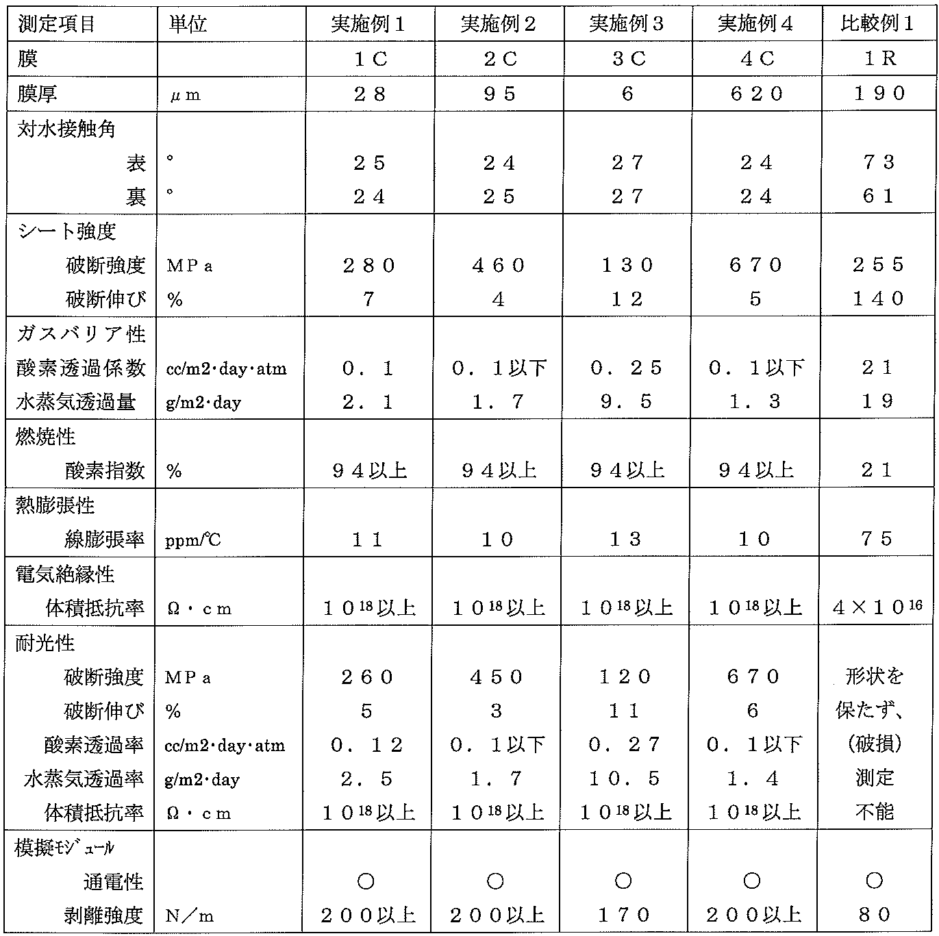
実施例1で作製した保護シート(粘土膜1C)の評価結果を、「表1」に示す。
<実施例2>
1.粘土膜シートの作製
実施例1と同様の操作で、天然モンモリロナイト40gと蒸留水600mlで得た均一な分散液を、ステンレス板上に厚さ3mmに塗布して60℃で24時間分乾燥した。さらに、実施例1と同様にプレスして、粘土膜2Cを得た。作製した保護シート(粘土膜2C)の評価結果を、「表1」に示す。
1.粘土膜シートの作製
実施例1と同様の操作で、天然モンモリロナイト40gと蒸留水600mlで得た均一な分散液を、ステンレス板上に厚さ3mmに塗布して60℃で24時間分乾燥した。さらに、実施例1と同様にプレスして、粘土膜2Cを得た。作製した保護シート(粘土膜2C)の評価結果を、「表1」に示す。
<実施例3>
1.粘土膜シートの作製
実施例1と同様の操作で、天然モンモリオナイト0.4gと蒸留水60gで得た均一な分散液を、ステンレス板上に厚さ2mmに塗布して60℃で24時間乾燥した。さらに、実施例1と同様にプレスして、粘土膜3Cを得た。作製した保護シート(粘土膜3C)の評価結果を、「表1」に示す。
1.粘土膜シートの作製
実施例1と同様の操作で、天然モンモリオナイト0.4gと蒸留水60gで得た均一な分散液を、ステンレス板上に厚さ2mmに塗布して60℃で24時間乾燥した。さらに、実施例1と同様にプレスして、粘土膜3Cを得た。作製した保護シート(粘土膜3C)の評価結果を、「表1」に示す。
<実施例4>
1.粘土膜シートの作製
実施例2と同様にして得た均一な分散液をステンレス板状に厚さ20mmに塗布して60℃で24時間乾燥し、さらに実施例1と同様にプレスして、粘土膜4Cを得た。作製した保護シート(粘土膜4C)の評価結果を、「表1」に示す。
1.粘土膜シートの作製
実施例2と同様にして得た均一な分散液をステンレス板状に厚さ20mmに塗布して60℃で24時間乾燥し、さらに実施例1と同様にプレスして、粘土膜4Cを得た。作製した保護シート(粘土膜4C)の評価結果を、「表1」に示す。
<比較例1>
1.樹脂膜シートの作製
二軸延伸PETフィルム(厚さ190μm、ルミラーT60、東レ株式会社)を用いてPET樹脂膜1Rを作製した。作製した保護シート(PET樹脂膜1R)の評価結果を、「表1」に示す。
1.樹脂膜シートの作製
二軸延伸PETフィルム(厚さ190μm、ルミラーT60、東レ株式会社)を用いてPET樹脂膜1Rを作製した。作製した保護シート(PET樹脂膜1R)の評価結果を、「表1」に示す。
<実施例5~8>
1.粘土膜/疎水性樹脂膜複層シートの作製
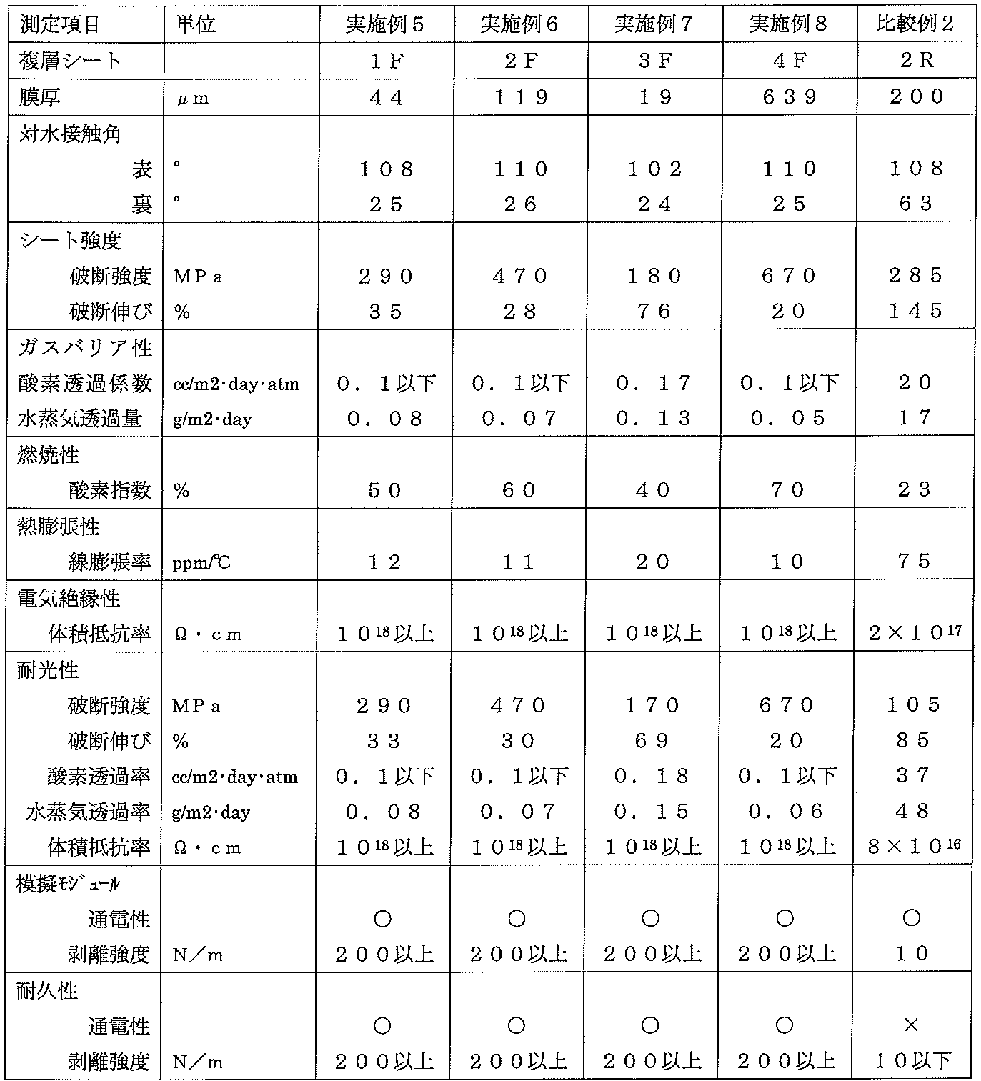
粘土膜1C~4Cと、ポリフッ化ビニリデン樹脂とポリメチルメタクリレート樹脂の8:2混合物のフッ素系樹脂膜(デンカDXフィルム、平均厚さ20μm、電気化学工業株式会社製)を重ね、上側をフッ素樹脂フィルムにして鏡面加工したステンレス板に挟み、油圧プレスで250℃/10MPaで10分圧着した。冷却後に剥離して得た保護シート(粘土膜/フッ素系樹脂複層シート1F~4F)の評価結果を、「表2」に示す。
1.粘土膜/疎水性樹脂膜複層シートの作製
粘土膜1C~4Cと、ポリフッ化ビニリデン樹脂とポリメチルメタクリレート樹脂の8:2混合物のフッ素系樹脂膜(デンカDXフィルム、平均厚さ20μm、電気化学工業株式会社製)を重ね、上側をフッ素樹脂フィルムにして鏡面加工したステンレス板に挟み、油圧プレスで250℃/10MPaで10分圧着した。冷却後に剥離して得た保護シート(粘土膜/フッ素系樹脂複層シート1F~4F)の評価結果を、「表2」に示す。
<比較例2>
1.樹脂膜複層シートの作製
粘土膜1Cの替わりに二軸延伸PETフィルム(厚さ190μm、ルミラーT60、東レ株式会社)を用いてPET樹脂フィルム/フッ素系樹脂複層シート2Rを作製し、特性評価を行った。結果を「表2」に示す。
1.樹脂膜複層シートの作製
粘土膜1Cの替わりに二軸延伸PETフィルム(厚さ190μm、ルミラーT60、東レ株式会社)を用いてPET樹脂フィルム/フッ素系樹脂複層シート2Rを作製し、特性評価を行った。結果を「表2」に示す。
<実施例9~12>
1.粘土膜/疎水性樹脂膜複層シートの作製
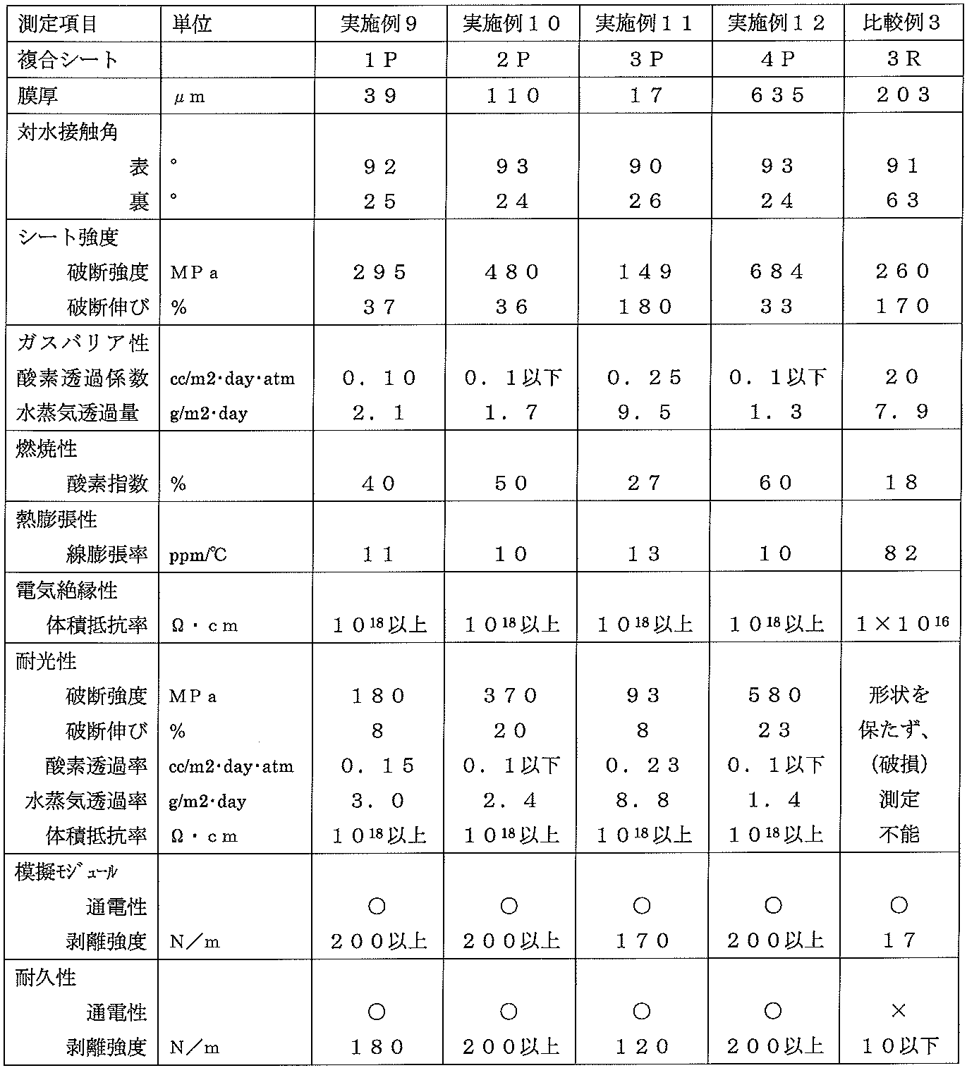
粘土膜1C~4Cと、無延伸ポリプロピレン樹脂膜(パイレンフィルムCT、P-1128,平均厚さ20μm、東洋紡株式会社)で、圧着温度を135℃とした以外は実施例5~8と同様の操作で粘土膜/ポリプロピレン樹脂膜複合シート1P~4Pを作製し、特性評価を行った。結果を「表3」に示す。
1.粘土膜/疎水性樹脂膜複層シートの作製
粘土膜1C~4Cと、無延伸ポリプロピレン樹脂膜(パイレンフィルムCT、P-1128,平均厚さ20μm、東洋紡株式会社)で、圧着温度を135℃とした以外は実施例5~8と同様の操作で粘土膜/ポリプロピレン樹脂膜複合シート1P~4Pを作製し、特性評価を行った。結果を「表3」に示す。
<比較例3>
1.樹脂膜複層シートの作製
粘土膜1Cの替わりに二軸延伸PETフィルム(厚さ190μm、ルミラーT60、東レ株式会社)を用いてPET樹脂膜/ポリプロピレン樹脂膜複合シート3Rを作製し、特性評価を行った。結果を「表3」に示す。
1.樹脂膜複層シートの作製
粘土膜1Cの替わりに二軸延伸PETフィルム(厚さ190μm、ルミラーT60、東レ株式会社)を用いてPET樹脂膜/ポリプロピレン樹脂膜複合シート3Rを作製し、特性評価を行った。結果を「表3」に示す。
<実施例13~16>
1.有機化粘土膜シートの作製
攪拌機を付けたガラスフラスコ中にモンモリロナイト(クニピアF,クニミネ工業株式会社)50gとテトラメチルアンモニウムクロリド34g及びイオン交換水500mlを秤量し、70℃で24時間攪拌した。遠心分離とイオン交換水分散を5回繰り返した後、強制循環式乾燥機中で60℃、24時間乾燥し、有機化モンモリロナイトを得た。
1.有機化粘土膜シートの作製
攪拌機を付けたガラスフラスコ中にモンモリロナイト(クニピアF,クニミネ工業株式会社)50gとテトラメチルアンモニウムクロリド34g及びイオン交換水500mlを秤量し、70℃で24時間攪拌した。遠心分離とイオン交換水分散を5回繰り返した後、強制循環式乾燥機中で60℃、24時間乾燥し、有機化モンモリロナイトを得た。
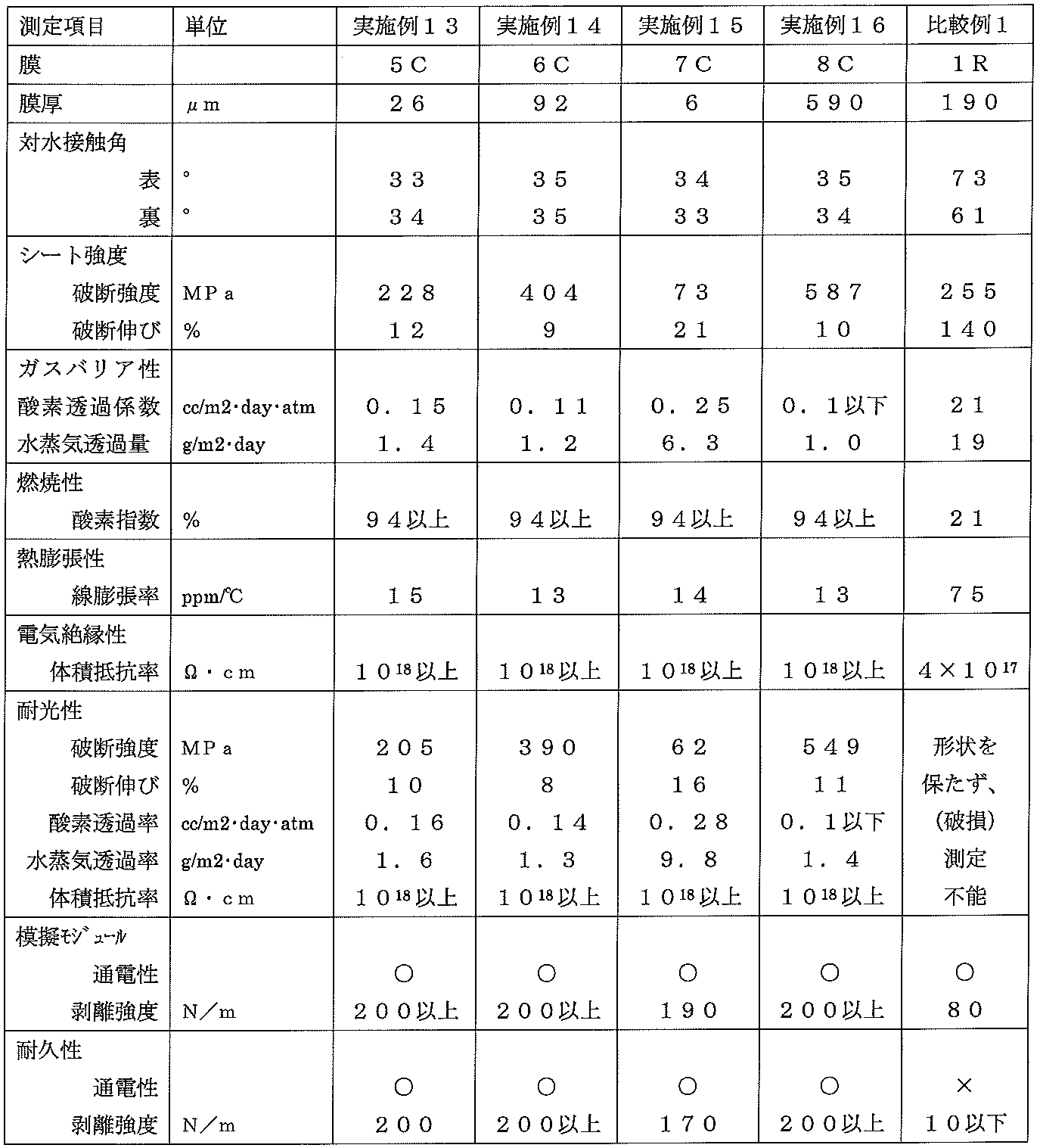
天然モンモリトナイトの替わりに、有機化モンモリロナイト/モンモリロナイトの1/1混合物(重量比)を用いて、実施例1~4と同様にして粘土膜5C~8Cを作製し、特性評価を行った。結果を「表4」に示す。
<実施例17~20>
1.有機化粘土膜/疎水性樹脂膜複層シートの作製
粘土膜5C~8Cを用いて、実施例5~8と同様にして粘土膜/フッ素樹脂膜複合シート5F~8Fを作製し、特性評価を行った。結果を「表5」に示す。
1.有機化粘土膜/疎水性樹脂膜複層シートの作製
粘土膜5C~8Cを用いて、実施例5~8と同様にして粘土膜/フッ素樹脂膜複合シート5F~8Fを作製し、特性評価を行った。結果を「表5」に示す。

<実施例21~24>
1.有機化粘土膜シートの作製
攪拌機を付けたガラスフラスコ中に500℃で2時間加熱処理したハイドロタルサイト(アルカマイザーDHT-4A,協和化学工業株式会社)50gとステアリン酸ナトリウム34g及びイオン交換水500mlを秤量し、80℃で6時間攪拌した。遠心分離とイオン交換水分散を5回繰り返した後、エタノールで洗浄した後、減圧乾燥機中60℃で24時間乾燥し、有機化ハイドロタルサイトを得た。
1.有機化粘土膜シートの作製
攪拌機を付けたガラスフラスコ中に500℃で2時間加熱処理したハイドロタルサイト(アルカマイザーDHT-4A,協和化学工業株式会社)50gとステアリン酸ナトリウム34g及びイオン交換水500mlを秤量し、80℃で6時間攪拌した。遠心分離とイオン交換水分散を5回繰り返した後、エタノールで洗浄した後、減圧乾燥機中60℃で24時間乾燥し、有機化ハイドロタルサイトを得た。
有機化及び有機化しないモンモリロナイトの替わりに有機化及び有機化しないハイドロタルサイトを用いて、実施例13~16と同様に、粘土膜9C~12Cを作製し、特性評価を行った。結果を「表6」に示す。

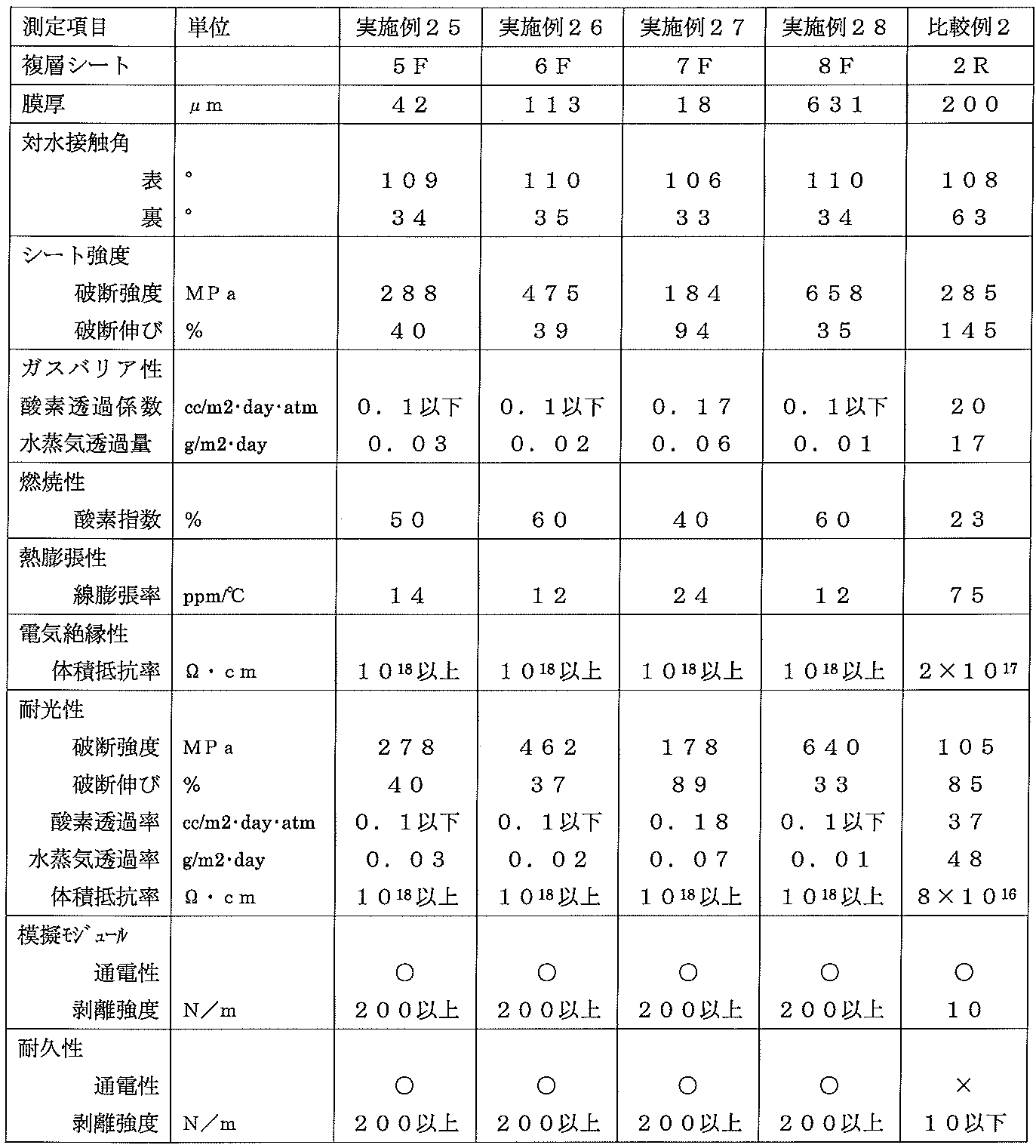
<実施例25~28>
1.有機化粘土膜/疎水性樹脂膜複層シートの作製
粘土膜9C~12Cを用いて、実施例5~8と同様にして有機化粘土膜/フッ素樹脂膜複合シート9F~12Fを作製し、特性評価を行った。結果を「表7」に示す。
1.有機化粘土膜/疎水性樹脂膜複層シートの作製
粘土膜9C~12Cを用いて、実施例5~8と同様にして有機化粘土膜/フッ素樹脂膜複合シート9F~12Fを作製し、特性評価を行った。結果を「表7」に示す。
本発明に係る太陽光発電モジュール用保護シートは、太陽光発電モジュールがおかれる過酷な気象環境に耐え得る耐久性と強度及び柔軟性を兼ね備え、かつ、ガスバリヤー性、水蒸気遮断性、耐熱・難燃性、電気絶縁性及び低熱膨張性等に優れる。従って、この保護シートを太陽光発電モジュールに装備することにより、太陽光発電モジュールの耐久性を高め、長期信頼性に優れた太陽光発電システムを構築することが可能となる。
Claims (11)
- 粘土成分の構成重量比が80%以上であり、厚さが1~1000μmである粘土膜層を含んでなる太陽光発電モジュール用保護シート。
- 対水接触角が60度以上であり、厚さが1~1000μmである疎水性樹脂膜層が、前記粘土膜層に積層された請求項1記載の太陽光発電モジュール用保護シート。
- 前記疎水性樹脂膜層におけるフッ素系樹脂の構成重量比が50%以上である請求項2記載の太陽光発電モジュール用保護シート。
- 前記粘土成分が、雲母、タルク、バーミキュライト、スメクタイト、ベントナイト、モンモリロナイト、鉄モンモリロナイト、バイデライト、サポナイト、ヘクトライト、スチーブンサイト及びノントロナイトからなる群から選択される一以上である請求項1~3のいずれか一項に記載の太陽光発電モジュール用保護シート。
- 前記粘土成分が、ハイドロタルサイト様化合物である請求項1~3のいずれか一項に記載の太陽光発電モジュール用保護シート。
- 前記粘土成分が、アンモニウム塩、ホスフォニウム塩及びイミダゾリウム塩からなる群から選択される有機性カチオン化合物により有機化された請求項1~4のいずれか一項に記載の太陽光発電モジュール用保護シート。
- 粘土膜層と疎水性樹脂膜層が直接積層された請求項2~6のいずれか一項に記載の太陽光発電モジュール用保護シート。
- 外表面の少なくとも一部に、請求項1~7のいずれか一項に記載の太陽光発電モジュール用保護シートを装着した太陽光発電モジュール。
- 請求項8記載の太陽光発電モジュールを含む太陽光発電システム。
- 粘土成分の重量比が80重量%以上であり、厚さが1~1000μmである粘土膜層と、対水接触角が60°以上であり、厚さが1~1000μmである疎水性樹脂膜層と、を、加熱圧着する工程を含む太陽光発電モジュール用保護シートの製造方法。
- 粘土成分の構成重量比が80%以上であり、厚さが1~1000μmである粘土膜層を含んでなる太陽光発電モジュール用保護シートを用いる太陽光発電モジュール保護方法。
Applications Claiming Priority (2)
| Application Number | Priority Date | Filing Date | Title |
|---|---|---|---|
| JP2008306970A JP5375055B2 (ja) | 2008-12-02 | 2008-12-02 | 太陽光発電モジュール用保護シート及びその製造方法、太陽光発電モジュール及びその保護方法、並びに太陽光発電システム |
| JP2008-306970 | 2008-12-02 |
Publications (1)
| Publication Number | Publication Date |
|---|---|
| WO2010064491A1 true WO2010064491A1 (ja) | 2010-06-10 |
Family
ID=42233146
Family Applications (1)
| Application Number | Title | Priority Date | Filing Date |
|---|---|---|---|
| PCT/JP2009/067753 Ceased WO2010064491A1 (ja) | 2008-12-02 | 2009-10-14 | 太陽光発電モジュール用保護シート、保護シートの製造方法及び太陽光発電モジュール保護方法 |
Country Status (3)
| Country | Link |
|---|---|
| JP (1) | JP5375055B2 (ja) |
| TW (1) | TW201026829A (ja) |
| WO (1) | WO2010064491A1 (ja) |
Cited By (6)
| Publication number | Priority date | Publication date | Assignee | Title |
|---|---|---|---|---|
| WO2012003416A1 (en) | 2010-07-02 | 2012-01-05 | 3M Innovative Properties Company | Barrier assembly |
| JP2012015346A (ja) * | 2010-07-01 | 2012-01-19 | Toyo Ink Sc Holdings Co Ltd | 太陽電池封止材用樹脂組成物 |
| WO2012088366A1 (en) * | 2010-12-22 | 2012-06-28 | E.I. Du Pont De Nemours And Company | Fire resistant back-sheet for photovoltaic module |
| US9050784B2 (en) | 2010-12-22 | 2015-06-09 | E I Du Pont De Nemours And Company | Fire resistant back-sheet for photovoltaic module |
| JP2018081988A (ja) * | 2016-11-15 | 2018-05-24 | 株式会社フジクラ | 光電変換素子 |
| US10636920B2 (en) | 2012-08-08 | 2020-04-28 | 3M Innovative Properties Company | Barrier film, method of making the barrier film, and articles including the barrier film |
Families Citing this family (7)
| Publication number | Priority date | Publication date | Assignee | Title |
|---|---|---|---|---|
| JP2010135654A (ja) * | 2008-12-08 | 2010-06-17 | Daiwa Gravure Co Ltd | 太陽電池モジュール用裏面保護シート |
| JP5553330B2 (ja) * | 2009-06-19 | 2014-07-16 | 独立行政法人産業技術総合研究所 | 電子デバイス用防湿フィルム及びその製造方法 |
| JP2012077147A (ja) * | 2010-09-30 | 2012-04-19 | Lintec Corp | 撥水シート |
| KR101444191B1 (ko) * | 2011-12-01 | 2014-09-30 | 한국생산기술연구원 | 열저항 나노복합체 투명필름 |
| JP2013183098A (ja) * | 2012-03-02 | 2013-09-12 | Lintec Corp | 太陽電池用保護シートおよびその製造方法、ならびに太陽電池モジュール |
| US20190140121A1 (en) * | 2016-05-31 | 2019-05-09 | Panasonic Intellectual Property Management Co., Ltd. | Solar cell module and manufacturing method thereof |
| WO2022024769A1 (ja) * | 2020-07-30 | 2022-02-03 | デンカ株式会社 | 積層フィルム及びその製造方法 |
Citations (4)
| Publication number | Priority date | Publication date | Assignee | Title |
|---|---|---|---|---|
| WO2007015534A1 (ja) * | 2005-08-03 | 2007-02-08 | National Institute Of Advanced Industrial Science And Technology | 透明膜 |
| JP2007277078A (ja) * | 2006-03-11 | 2007-10-25 | National Institute Of Advanced Industrial & Technology | 変性粘土を用いた膜 |
| WO2008123304A1 (ja) * | 2007-03-27 | 2008-10-16 | Tomoegawa Co., Ltd. | 粘土、粘土薄膜、及びその積層体 |
| JP2008274043A (ja) * | 2007-04-26 | 2008-11-13 | Asahi Kasei Corp | 膜及びその製造方法 |
Family Cites Families (1)
| Publication number | Priority date | Publication date | Assignee | Title |
|---|---|---|---|---|
| US5518704A (en) * | 1993-07-06 | 1996-05-21 | Aristech Chemical Corporation | Nickel and cobalt containing hydrotalcite-like materials having a sheet-like morphology and process for production thereof |
-
2008
- 2008-12-02 JP JP2008306970A patent/JP5375055B2/ja not_active Expired - Fee Related
-
2009
- 2009-10-14 WO PCT/JP2009/067753 patent/WO2010064491A1/ja not_active Ceased
- 2009-10-28 TW TW098136456A patent/TW201026829A/zh unknown
Patent Citations (4)
| Publication number | Priority date | Publication date | Assignee | Title |
|---|---|---|---|---|
| WO2007015534A1 (ja) * | 2005-08-03 | 2007-02-08 | National Institute Of Advanced Industrial Science And Technology | 透明膜 |
| JP2007277078A (ja) * | 2006-03-11 | 2007-10-25 | National Institute Of Advanced Industrial & Technology | 変性粘土を用いた膜 |
| WO2008123304A1 (ja) * | 2007-03-27 | 2008-10-16 | Tomoegawa Co., Ltd. | 粘土、粘土薄膜、及びその積層体 |
| JP2008274043A (ja) * | 2007-04-26 | 2008-11-13 | Asahi Kasei Corp | 膜及びその製造方法 |
Cited By (10)
| Publication number | Priority date | Publication date | Assignee | Title |
|---|---|---|---|---|
| JP2012015346A (ja) * | 2010-07-01 | 2012-01-19 | Toyo Ink Sc Holdings Co Ltd | 太陽電池封止材用樹脂組成物 |
| WO2012003416A1 (en) | 2010-07-02 | 2012-01-05 | 3M Innovative Properties Company | Barrier assembly |
| US8628859B2 (en) | 2010-07-02 | 2014-01-14 | 3M Innovative Properties Company | Barrier film |
| US9997657B2 (en) | 2010-07-02 | 2018-06-12 | 3M Innovative Properties Company | Barrier assembly |
| US10038111B2 (en) | 2010-07-02 | 2018-07-31 | 3M Innovative Properties Company | Barrier assembly with encapsulant and photovoltaic cell |
| US10693024B2 (en) | 2010-07-02 | 2020-06-23 | 3M Innovative Properties Company | Barrier assembly |
| WO2012088366A1 (en) * | 2010-12-22 | 2012-06-28 | E.I. Du Pont De Nemours And Company | Fire resistant back-sheet for photovoltaic module |
| US9050784B2 (en) | 2010-12-22 | 2015-06-09 | E I Du Pont De Nemours And Company | Fire resistant back-sheet for photovoltaic module |
| US10636920B2 (en) | 2012-08-08 | 2020-04-28 | 3M Innovative Properties Company | Barrier film, method of making the barrier film, and articles including the barrier film |
| JP2018081988A (ja) * | 2016-11-15 | 2018-05-24 | 株式会社フジクラ | 光電変換素子 |
Also Published As
| Publication number | Publication date |
|---|---|
| JP2010135349A (ja) | 2010-06-17 |
| JP5375055B2 (ja) | 2013-12-25 |
| TW201026829A (en) | 2010-07-16 |
Similar Documents
| Publication | Publication Date | Title |
|---|---|---|
| JP5375055B2 (ja) | 太陽光発電モジュール用保護シート及びその製造方法、太陽光発電モジュール及びその保護方法、並びに太陽光発電システム | |
| US10020406B2 (en) | Protective film for solar cell and solar cell comprising the same | |
| EP2581944A1 (en) | Solar cell module | |
| AU2007292675A1 (en) | Seal film for solar cell module and solar cell module utilizing the same | |
| JPWO2011152500A1 (ja) | 水蒸気バリア性フィルム及びその製造方法 | |
| KR101909405B1 (ko) | 하이브리드 태양전지 모듈 | |
| JP2009085255A (ja) | 真空断熱材およびそれを用いた機器 | |
| WO2013145116A1 (ja) | 太陽電池モジュール用封止フィルム、およびそれを用いた太陽電池モジュール | |
| CN103009688A (zh) | 层合阻燃片 | |
| JP2015057811A (ja) | 太陽電池モジュール | |
| Dang et al. | A flexible, robust and multifunctional montmorillonite/aramid nanofibers@ MXene electromagnetic shielding nanocomposite with an alternating structure for enhanced Joule heating and fire-resistant protective performance | |
| JP5820109B2 (ja) | 太陽電池モジュール用封止フィルム、およびそれを用いた太陽電池モジュール | |
| JP4836166B2 (ja) | 粘着粘土膜及びその使用方法 | |
| CN223364481U (zh) | 光伏组件和光伏系统 | |
| JP2014038925A (ja) | 防炎太陽電池モジュール | |
| JP5310436B2 (ja) | 太陽電池モジュール及びその製造方法 | |
| JP5741451B2 (ja) | 太陽電池モジュール及び太陽電池モジュールの製造方法 | |
| JP2013030734A (ja) | 太陽電池モジュール | |
| CN103928553A (zh) | 一种柔性晶硅太阳能电池组件 | |
| JP2015185680A (ja) | 太陽電池モジュール | |
| KR20130135508A (ko) | 태양전지용 보호필름 및 이를 포함하는 태양전지 | |
| JP2015135914A (ja) | 太陽電池モジュール一体型膜材 | |
| CN103507360B (zh) | 包含全氟化聚合物层的多层结构 | |
| TWI886969B (zh) | 太陽能電池模組 | |
| TW201324803A (zh) | 太陽能發電模組 |
Legal Events
| Date | Code | Title | Description |
|---|---|---|---|
| 121 | Ep: the epo has been informed by wipo that ep was designated in this application |
Ref document number: 09830259 Country of ref document: EP Kind code of ref document: A1 |
|
| NENP | Non-entry into the national phase |
Ref country code: DE |
|
| 122 | Ep: pct application non-entry in european phase |
Ref document number: 09830259 Country of ref document: EP Kind code of ref document: A1 |