WO2010064396A1 - 動画像復号化方法および動画像符号化方法 - Google Patents
動画像復号化方法および動画像符号化方法 Download PDFInfo
- Publication number
- WO2010064396A1 WO2010064396A1 PCT/JP2009/006438 JP2009006438W WO2010064396A1 WO 2010064396 A1 WO2010064396 A1 WO 2010064396A1 JP 2009006438 W JP2009006438 W JP 2009006438W WO 2010064396 A1 WO2010064396 A1 WO 2010064396A1
- Authority
- WO
- WIPO (PCT)
- Prior art keywords
- motion vector
- vector
- block
- prediction
- calculated
- Prior art date
Links
Images
Classifications
-
- H—ELECTRICITY
- H04—ELECTRIC COMMUNICATION TECHNIQUE
- H04N—PICTORIAL COMMUNICATION, e.g. TELEVISION
- H04N19/00—Methods or arrangements for coding, decoding, compressing or decompressing digital video signals
- H04N19/50—Methods or arrangements for coding, decoding, compressing or decompressing digital video signals using predictive coding
- H04N19/503—Methods or arrangements for coding, decoding, compressing or decompressing digital video signals using predictive coding involving temporal prediction
- H04N19/51—Motion estimation or motion compensation
- H04N19/513—Processing of motion vectors
- H04N19/517—Processing of motion vectors by encoding
- H04N19/52—Processing of motion vectors by encoding by predictive encoding
-
- H—ELECTRICITY
- H04—ELECTRIC COMMUNICATION TECHNIQUE
- H04N—PICTORIAL COMMUNICATION, e.g. TELEVISION
- H04N19/00—Methods or arrangements for coding, decoding, compressing or decompressing digital video signals
- H04N19/10—Methods or arrangements for coding, decoding, compressing or decompressing digital video signals using adaptive coding
- H04N19/102—Methods or arrangements for coding, decoding, compressing or decompressing digital video signals using adaptive coding characterised by the element, parameter or selection affected or controlled by the adaptive coding
- H04N19/124—Quantisation
-
- H—ELECTRICITY
- H04—ELECTRIC COMMUNICATION TECHNIQUE
- H04N—PICTORIAL COMMUNICATION, e.g. TELEVISION
- H04N19/00—Methods or arrangements for coding, decoding, compressing or decompressing digital video signals
- H04N19/10—Methods or arrangements for coding, decoding, compressing or decompressing digital video signals using adaptive coding
- H04N19/102—Methods or arrangements for coding, decoding, compressing or decompressing digital video signals using adaptive coding characterised by the element, parameter or selection affected or controlled by the adaptive coding
- H04N19/13—Adaptive entropy coding, e.g. adaptive variable length coding [AVLC] or context adaptive binary arithmetic coding [CABAC]
-
- H—ELECTRICITY
- H04—ELECTRIC COMMUNICATION TECHNIQUE
- H04N—PICTORIAL COMMUNICATION, e.g. TELEVISION
- H04N19/00—Methods or arrangements for coding, decoding, compressing or decompressing digital video signals
- H04N19/10—Methods or arrangements for coding, decoding, compressing or decompressing digital video signals using adaptive coding
- H04N19/134—Methods or arrangements for coding, decoding, compressing or decompressing digital video signals using adaptive coding characterised by the element, parameter or criterion affecting or controlling the adaptive coding
- H04N19/157—Assigned coding mode, i.e. the coding mode being predefined or preselected to be further used for selection of another element or parameter
- H04N19/159—Prediction type, e.g. intra-frame, inter-frame or bidirectional frame prediction
-
- H—ELECTRICITY
- H04—ELECTRIC COMMUNICATION TECHNIQUE
- H04N—PICTORIAL COMMUNICATION, e.g. TELEVISION
- H04N19/00—Methods or arrangements for coding, decoding, compressing or decompressing digital video signals
- H04N19/44—Decoders specially adapted therefor, e.g. video decoders which are asymmetric with respect to the encoder
-
- H—ELECTRICITY
- H04—ELECTRIC COMMUNICATION TECHNIQUE
- H04N—PICTORIAL COMMUNICATION, e.g. TELEVISION
- H04N19/00—Methods or arrangements for coding, decoding, compressing or decompressing digital video signals
- H04N19/50—Methods or arrangements for coding, decoding, compressing or decompressing digital video signals using predictive coding
- H04N19/503—Methods or arrangements for coding, decoding, compressing or decompressing digital video signals using predictive coding involving temporal prediction
- H04N19/51—Motion estimation or motion compensation
-
- H—ELECTRICITY
- H04—ELECTRIC COMMUNICATION TECHNIQUE
- H04N—PICTORIAL COMMUNICATION, e.g. TELEVISION
- H04N19/00—Methods or arrangements for coding, decoding, compressing or decompressing digital video signals
- H04N19/60—Methods or arrangements for coding, decoding, compressing or decompressing digital video signals using transform coding
- H04N19/61—Methods or arrangements for coding, decoding, compressing or decompressing digital video signals using transform coding in combination with predictive coding
-
- H—ELECTRICITY
- H04—ELECTRIC COMMUNICATION TECHNIQUE
- H04N—PICTORIAL COMMUNICATION, e.g. TELEVISION
- H04N19/00—Methods or arrangements for coding, decoding, compressing or decompressing digital video signals
- H04N19/10—Methods or arrangements for coding, decoding, compressing or decompressing digital video signals using adaptive coding
- H04N19/169—Methods or arrangements for coding, decoding, compressing or decompressing digital video signals using adaptive coding characterised by the coding unit, i.e. the structural portion or semantic portion of the video signal being the object or the subject of the adaptive coding
- H04N19/17—Methods or arrangements for coding, decoding, compressing or decompressing digital video signals using adaptive coding characterised by the coding unit, i.e. the structural portion or semantic portion of the video signal being the object or the subject of the adaptive coding the unit being an image region, e.g. an object
- H04N19/172—Methods or arrangements for coding, decoding, compressing or decompressing digital video signals using adaptive coding characterised by the coding unit, i.e. the structural portion or semantic portion of the video signal being the object or the subject of the adaptive coding the unit being an image region, e.g. an object the region being a picture, frame or field
-
- H—ELECTRICITY
- H04—ELECTRIC COMMUNICATION TECHNIQUE
- H04N—PICTORIAL COMMUNICATION, e.g. TELEVISION
- H04N19/00—Methods or arrangements for coding, decoding, compressing or decompressing digital video signals
- H04N19/10—Methods or arrangements for coding, decoding, compressing or decompressing digital video signals using adaptive coding
- H04N19/169—Methods or arrangements for coding, decoding, compressing or decompressing digital video signals using adaptive coding characterised by the coding unit, i.e. the structural portion or semantic portion of the video signal being the object or the subject of the adaptive coding
- H04N19/17—Methods or arrangements for coding, decoding, compressing or decompressing digital video signals using adaptive coding characterised by the coding unit, i.e. the structural portion or semantic portion of the video signal being the object or the subject of the adaptive coding the unit being an image region, e.g. an object
- H04N19/176—Methods or arrangements for coding, decoding, compressing or decompressing digital video signals using adaptive coding characterised by the coding unit, i.e. the structural portion or semantic portion of the video signal being the object or the subject of the adaptive coding the unit being an image region, e.g. an object the region being a block, e.g. a macroblock
-
- H—ELECTRICITY
- H04—ELECTRIC COMMUNICATION TECHNIQUE
- H04N—PICTORIAL COMMUNICATION, e.g. TELEVISION
- H04N19/00—Methods or arrangements for coding, decoding, compressing or decompressing digital video signals
- H04N19/10—Methods or arrangements for coding, decoding, compressing or decompressing digital video signals using adaptive coding
- H04N19/169—Methods or arrangements for coding, decoding, compressing or decompressing digital video signals using adaptive coding characterised by the coding unit, i.e. the structural portion or semantic portion of the video signal being the object or the subject of the adaptive coding
- H04N19/184—Methods or arrangements for coding, decoding, compressing or decompressing digital video signals using adaptive coding characterised by the coding unit, i.e. the structural portion or semantic portion of the video signal being the object or the subject of the adaptive coding the unit being bits, e.g. of the compressed video stream
Definitions
- the present invention relates to a moving picture decoding technique for decoding a moving picture and a moving picture encoding technique for encoding a moving picture.
- Non-Patent Document 1 discloses a prediction technique for motion vectors in order to reduce the amount of coding of the motion vectors.
- the motion vector of the target block is predicted using an encoded block located around the target block, and the difference between the prediction vector and the motion vector (difference vector) is variable. Encode long. However, it cannot be said that the prediction accuracy of motion vectors is sufficient, and there is a problem that a large amount of code is still required for motion vectors, especially for images with complex motion, such as the presence of multiple moving objects. .
- the above technique still requires a large amount of code for the motion vector because the prediction accuracy of the motion vector is not sufficiently high.
- the present invention has been made in view of the above problems, and an object of the present invention is to improve a calculation method of a prediction vector, to reduce a code amount of a motion vector, and to improve compression efficiency.
- an embodiment of the present invention may be configured as described in the claims, for example.
- the block diagram of the image coding apparatus in this invention The block diagram of the image coding apparatus in this invention Block diagram of an image decoding apparatus in the present invention Block diagram of an image decoding apparatus in the present invention Conceptual illustration of inter-screen prediction in H.264 / AVC Conceptual illustration of motion vector prediction technology in H.264 / AVC Conceptual explanatory diagram regarding motion vector prediction technology in Examples 1, 2, and 3. Conceptual explanatory diagram regarding motion vector prediction technology in Examples 1, 2, and 3.
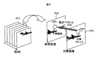
- Fig. 5 conceptually shows the operation of inter-screen prediction processing by H.264 / AVC.
- encoding is performed on a block-by-block basis in accordance with the raster scan order for the encoding target image.
- the decoded image of the encoded image included in the same video (501) as the encoding target image (503) is set as the reference image (502), and the target block (504) in the target image A block (predicted image) (505) having a high correlation with the reference image is searched from the reference image.
- the difference between the coordinate values of both blocks is encoded as a motion vector (506).
- the reverse procedure described above may be performed, and the decoded image can be acquired by adding the decoded prediction difference to the block (predicted image) (505) in the reference image.
- H.264 / AVC introduces motion vector prediction technology to reduce the overhead of the code amount due to the motion vector described above. That is, when encoding a motion vector, the motion vector of the target block is predicted using an encoded block located around the target block, and a difference (difference vector) between the prediction vector and the motion vector is calculated. Encode. At this time, since the size of the difference vector is concentrated to almost zero, the amount of codes can be reduced by variable-length coding this.
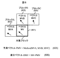
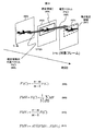
- FIG. 6 conceptually shows a method for calculating a prediction vector.
- the encoded blocks adjacent to the left side, the upper side, and the upper right side of the target block 601 (601) are the block A (602), the block B (603), and the block C (604), respectively, and the motion vector MV in each block is MVA, MVB and MVC.
- the prediction vector is represented as a median value of MVA, MVB, and MVC. That is, the prediction vector PMV is calculated as shown in (605) using the function Median that returns the median value for each component of the vector specified as the argument.
- the difference vector DMV is calculated as a difference (606) between the motion vector MV of the target block and the prediction vector PMV, and then the difference vector DMV is variable length encoded.
- the reverse procedure described above may be performed, and the motion vector MV is decoded by adding the decoded difference vector DMV to the prediction vector PMV calculated by the same procedure as described above.
- the amount of code required for motion vectors can be significantly reduced by introducing a prediction technique for motion vectors.
- a prediction technique for motion vectors only the neighboring blocks in the screen are considered when calculating the prediction vector, and it cannot be said that the motion of the object is necessarily reflected. For this reason, particularly when there are a plurality of moving objects in the vicinity region, it cannot be said that the prediction accuracy of the motion vector is sufficient, and a large amount of code is still required for the motion vector.
- the presence and range of a motion region are estimated by integrating the motion vectors of the already-encoded regions that have similar values, and the prediction vector is based on the motion vector of the motion region that exists in the vicinity of the target region. By calculating, the prediction accuracy for the motion vector can be improved.
- the calculation procedure of the prediction vector PMV is the same on the encoding side and the decoding side, and the encoding side calculates a difference vector DMV between the motion vector MV and the prediction vector PMV and encodes it.
- the decoding side a process of decoding the motion vector MV by adding the prediction vector PMV to the decoded difference vector DMV is performed.
- Example 1 uses the information of the integrated area when calculating the prediction vector of the target block. That is, if an integrated region exists around the target block, it is determined that the target block also includes a part of the same object as the object included in the integrated region, and the prediction vector is based on the motion vector of the block included in the integrated region. Is calculated.
- the prediction vector can be calculated based on the motion vector of the motion area existing in the vicinity of the target area, the prediction accuracy for the motion vector can be improved.
- the prediction vector calculation method can be improved to reduce the amount of motion vector codes, thereby improving the compression efficiency.
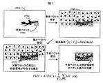
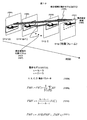
- FIG. 7 is a diagram conceptually showing an example of a prediction vector PMV calculation method in the present embodiment.
- the motion vectors MV (704) in the already-encoded region located on the left or above the target block (703) are integrated with each other.
- ⁇ Threshold is satisfied, the two motion vectors V1 and V2 are integrated and included in the same region.
- Threshold is a constant.
- the constant Threshold may be set to a unique value in advance, or the value may be freely set on the encoding side and included in the encoded stream. Alternatively, it may be dynamically determined based on encoding information such as a variance value and an average value of the motion vector MV, the size of the integrated region, and the like. In particular, this mathematical formula need not be followed. Furthermore, information other than the motion vector MV, such as color information, may be taken into consideration during integration.
- the motion vector MV of an area including a part of the same object has a property of showing values close to each other, it is possible to specify the existence and range of the object (702) by acquiring the integrated area (705). it can.
- the information of the integrated region (705) is used when calculating the prediction vector PMV of the target block (703). That is, when the integrated region (705) exists around the target block (703), it is determined that the target block (703) also includes a part of the same object as the object (702) included in the integrated region (705).
- the prediction vector PMV is calculated based on the motion vector MV of the blocks included in the integrated region (705).
- the calculation method of the prediction vector PMV is not particularly limited.
- the prediction vector PMV may be calculated as an average value (AVE (C)) of the motion vectors MV in the integrated region, as in Expression (706) of FIG.
- the prediction vector PMV may be calculated by selecting a representative motion vector MV in the integrated region, such as an intermediate value of the motion vector MV in the region.
- C is a set of motion vectors MV included in the integrated region
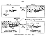
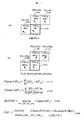
- the prediction vector PMV is calculated according to the procedure shown in FIG.
- a frame (801) similar to FIG. 7 in which a frame (801) shows a block (803) that is distant from the object (802) is inter-coded.
- the motion vector MV (804) in the already-encoded area is integrated in the same procedure as in FIG. 7 to obtain the integrated area (805).
- the prediction vector PMV is calculated (806) by the conventional calculation formula (807) using the motion vector MV of the peripheral block of the target block (803) such as H.264.
- the conventional method is not limited to H.264.
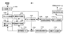
- FIG. 1 shows an example of a moving picture coding apparatus according to the present embodiment.
- the moving image encoding apparatus includes an input image memory (102) that holds an input original image (101), and a block that divides image data input from the input image memory (102) into a plurality of regions.
- An inter-screen prediction unit (106) that performs inter-screen prediction on a block basis using the motion vector MV detected by the motion vector calculation unit (104), and a predictive encoding means (prediction method and block size).
- Quantizer (110) that quantizes the predicted difference data
- the input image memory (102) holds one of the original images (101) as an encoding target image, and outputs this to the block dividing unit (103).
- the block dividing unit (103) divides the original image (101) into a plurality of blocks, and outputs the blocks to the motion vector calculating unit (104), the intra prediction unit (105), and the inter prediction unit (106).
- the motion vector calculation unit (104) calculates the motion vector MV of the target block using the decoded image stored in the reference image memory (115), and outputs the motion vector MV to the inter-screen prediction unit (106). To do.
- the intra-screen prediction unit (105) and the inter-screen prediction unit (106) execute intra-screen prediction processing and inter-screen prediction processing in units of blocks, and the mode selection unit (107) includes the intra-screen prediction processing and inter-screen prediction processing.
- the optimum predictive encoding means is selected with reference to the result of (1).
- the subtraction unit (108) generates prediction difference data by the optimal prediction encoding means, and outputs it to the frequency conversion unit (109).
- the frequency conversion unit (109) and the quantization processing unit (110) perform frequency conversion and quantization processing such as DCT (Discrete Cosine Transformation) on the input prediction difference data in units of blocks. And output to the variable length coding processing unit (111) and the inverse quantization processing unit (112).
- DCT Discrete Cosine Transformation
- variable length coding processing unit (111) includes the prediction difference information represented by the frequency transform coefficient, the prediction direction data used when performing intra-screen prediction, for example, and the motion vector MV used when performing inter-screen prediction.
- variable length coding is performed on the basis of the occurrence probability of symbols, such as assigning a short code length to symbols having a high occurrence frequency for information necessary for decoding, etc., to generate an encoded stream.
- the inverse quantization processing unit (112) and the inverse frequency transform unit (113) perform inverse frequency transform such as inverse quantization and IDCT (Inverse DCT: inverse DCT) on the frequency transform coefficients after quantization, Prediction difference data is acquired and output to the addition unit (114).
- the adder (114) generates a decoded image and outputs it to the reference image memory (115), and the reference image memory (115) stores the generated decoded image.
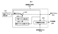
- the inter-screen prediction unit (106) will be described with reference to FIG.
- An inter-screen prediction unit (106) includes a motion vector storage memory (201) for storing a motion vector MV of an already-encoded area, and a prediction vector for calculating a prediction vector PMV using the motion vector MV of the already-encoded area
- a calculation unit (202) a subtractor (203) that calculates a difference vector DMV by calculating a difference between the motion vector MV and the prediction vector PMV, and a prediction image generation unit (204) that generates a prediction image.
- the prediction vector calculation unit (202) calculates the prediction vector PMV of the target block based on the motion vector MV of the already-encoded area stored in the motion vector storage memory (201).
- the subtraction unit (203) calculates a difference between the motion vector MV calculated by the motion vector calculation unit (104) and the prediction vector PMV to calculate a difference vector DMV (205).
- the predicted image generation unit (204) generates a predicted image (206) from the motion vector MV and the reference image.
- the motion vector storage memory (201) stores a motion vector MV.
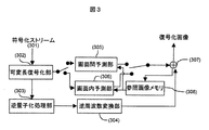
- FIG. 3 shows an example of a moving picture decoding apparatus in the present embodiment.
- the moving picture decoding apparatus for example, a variable length decoding unit that performs the reverse procedure of variable length coding on the encoded stream (301) generated by the moving picture encoding apparatus shown in FIG. 302), an inverse quantization processing unit (303) that inverse quantizes the prediction difference data, and an inverse frequency conversion unit (304) that performs inverse frequency conversion on the data inversely quantized by the inverse quantization processing unit (303),
- the variable length decoding unit (302) performs variable length decoding on the encoded stream (301), and acquires information necessary for prediction processing, such as a frequency conversion coefficient component of a prediction difference, a block size, and a motion vector MV.
- the frequency transform coefficient component of the prediction difference is sent to the inverse quantization processing unit (303), and the block size and motion vector MV are sent to the inter-screen prediction unit (305) or the intra-screen prediction unit (306).
- An inverse quantization processing unit (303) and an inverse frequency transform unit (304) perform inverse quantization and inverse frequency transform on the prediction difference information, respectively, and decode the prediction difference data.
- the inter-screen prediction unit (305) and the intra-screen prediction unit (306) perform prediction processing based on the image information input from the variable length decoding unit (302) and the reference image stored in the reference image memory (308). I do.
- the adding unit (307) decodes based on the prediction difference data input from the variable length decoding unit (302) and the predicted image data input from the inter-screen prediction unit (305) or the intra-screen prediction unit (306). Generate a digitized image.
- the reference image memory (308) stores the decoded image input from the addition unit (307).
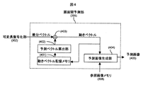
- the inter-screen prediction unit (305) will be described with reference to FIG.
- the inter-screen prediction unit (305) includes a motion vector storage memory (401) that stores a motion vector MV of a previously decoded area, and a prediction vector calculation unit that calculates a prediction vector PMV using the motion vector MV of the already decoded area (402), an adder (403) that calculates a motion vector MV by calculating the sum of the difference vector DMV and the prediction vector PMV, and a prediction image generation unit (404) that generates a prediction image.
- the prediction vector calculation unit (402) calculates the prediction vector PMV of the target block based on the motion vector MV of the already decoded area stored in the motion vector storage memory (401).
- the adding unit (404) calculates the sum of the difference vector DMV and the prediction vector PMV decoded by the variable length decoding unit (302), and decodes the motion vector MV.
- the motion vector storage memory (401) stores the decoded motion vector MV.
- the predicted image generation unit (404) generates a predicted image (405) from the motion vector MV and the reference image.
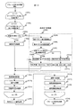
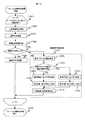
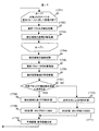
- FIG. 12 is a diagram showing an encoding processing procedure in the present embodiment.
- the following processing is performed for all blocks existing in the frame to be encoded (1201). That is, prediction is performed for all coding modes (combination of prediction method and block size) for the target block (1202).
- in-screen prediction (1204) or inter-screen prediction (1220) is performed according to the prediction mode, and a prediction difference is calculated.
- inter-screen prediction (1220) the motion vector MV is encoded in addition to the prediction difference (1205).
- integration processing is performed on the motion vector MV of the already-encoded region (1206), and it is determined whether or not there is an integration region around the target block (1207).
- the prediction vector PMV is calculated based on the motion vector MV included in the integrated region (1208), and the difference from the motion vector MV is calculated, thereby calculating the difference vector DMV. Obtain (1209).
- the prediction vector PMV is calculated by a conventional method such as H.264 (1210), and the difference vector DMV is acquired (1211). Subsequently, frequency conversion processing (1212), quantization processing (1213), and variable length encoding processing (1214) are performed on the prediction difference data, and image quality distortion and code amount of each encoding mode are calculated.
- an encoding mode with the highest encoding efficiency is selected based on the result (1215).
- an RD-Optimization method that determines an optimum coding mode from the relationship between image quality distortion and code amount. Thus, it can be encoded efficiently. See Reference 1 for details of the RD-Optimization method. (Reference 1) G. Sullivan and T. Wiegand: “Rate-Distortion Optimization for Video Compression”, IEEE Signal Processing Magazine, vol.15, no.6, pp.74-90, 1998.
- the quantized frequency transform coefficient is subjected to inverse quantization processing (1216) and inverse frequency transform processing (1217) to decode the prediction difference data, and the decoded image is It is generated (1218) and stored in the reference image memory.
- the encoding for one frame of the image is completed (1219).
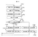
- FIG. 13 is a diagram showing a decoding process procedure of one frame in the present embodiment.
- the following processing is performed for all blocks in one frame (1301). That is, the variable length decoding process is performed on the input stream (1302), the inverse quantization process (1303), and the inverse frequency conversion process (1304) are performed to decode the prediction difference data. Subsequently, in-screen prediction processing (1306) and inter-screen prediction processing (1315) are performed according to the prediction mode. Note that when performing inter-screen prediction, the motion vector MV is decoded.
- integration processing is performed on the motion vector MV of the already decoded area (1307), and it is determined whether or not there is an integrated area around the target block (1308).
- the prediction vector PMV is calculated based on the motion vector MV included in the integrated region (1309), and is added to the difference vector DMV to obtain the motion vector MV of the target block (1310).
- the prediction vector PMV is calculated by a conventional method such as H.264 (1311), and the motion vector MV is calculated (1312).
- a predicted image and a decoded image are generated using the calculated motion vector MV (1313).
- the prediction vector PMV is calculated in units of blocks.
- the prediction vector PMV may be calculated in units of objects separated from the background of the image.
- DCT is cited as an example of frequency transformation
- DST Discrete Sine Transformation
- WT Widelet Transformation
- DFT Discrete Fourier Transformation
- KLT Kerhunen-Loeve
- Any kind of orthogonal transformation can be used as long as it is used for removing the correlation between pixels, such as Transformation (Karunen-Reeve transformation).
- the prediction difference itself may be encoded without performing frequency conversion.
- variable length coding need not be performed.
- the prediction vector PMV is calculated based on the motion vector MV included in the integrated region, but the motion vector itself may be calculated using this.
- the target block when an integrated region exists around the target block, it is determined that the target block also includes a part of the same object as the object included in the integrated region, and based on the motion vector of the block included in the integrated region To calculate a prediction vector.
- the prediction precision with respect to a motion vector can be improved.
- the prediction vector calculation method can be improved to reduce the amount of motion vector codes, thereby improving the compression efficiency.
- the prediction accuracy is improved when the target block is included in the surrounding object region.
- the prediction vector PMV of the target block is calculated using past frames that have been encoded or decoded. Thereby, for example, it is possible to improve the prediction accuracy when the target block is located at the boundary of the object region.
- FIG. 9 is a diagram showing an example using an encoded past frame.
- It can be represented by the representative value F (C) (905).
- the representative value F (C) may be calculated from an average value, a weighted average value, a median value, or the like of motion vectors included in the integrated region. It is assumed that k ⁇ m ⁇ n.
- the correction vector F for estimating where the integrated region (904) moves in the target frame (901) '(C) (906) can be calculated. This makes it possible to estimate the motion estimation region (907) on the target frame (903) corresponding to the integrated region (904) in the past frame (902).
- the prediction vector PMV is calculated based on the motion vector MV included in the integrated region (904).
- the prediction vector PMV may be calculated as the average value AVE (C) of the motion vectors MV included in the integrated region (904), or one vector included in the integrated region (904) may be selected.
- the prediction vector PMV may be calculated using a conventional method such as H.264.
- the prediction vector PMV can be calculated by, for example, Expression (909), Expression (910), Expression (911), and the like.
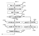
- FIG. 14 is a diagram showing an encoding procedure in the present embodiment. Here, only the inter-screen prediction process (1220) in FIG. 12 is described, and the other operations are the same as those in FIG.
- motion vector calculation and difference image calculation are performed (1401). Subsequently, integration processing is performed on the motion vector MV in the past frame (1402), and it is effective if it is calculated as a representative vector (for example, an average value vector) of the integration region. Hereinafter, it is described as “average vector”. ) Is calculated (1403). Next, based on the average vector and the time information of the past frame, a correction vector indicating where the integrated region in the past frame moves in the encoding target frame is calculated (1404), and the motion estimation region is specified. It is determined whether or not the target block is included in the motion estimation region (1405). If the target block is included in the motion estimation region, the prediction vector PMV is calculated based on the motion vector MV included in the integrated region.
- a difference vector DMV is obtained by calculating a difference between the prediction vector PMV and the motion vector MV (1407).
- a prediction vector PMV is calculated by a conventional method such as H.264 (1408), and a difference vector DMV is obtained (1409).
- FIG. 15 is a diagram showing a decoding procedure in the present embodiment. Here, only the inter-screen prediction process (1315) in FIG. 13 is described, and the other operations are the same as those in FIG.
- integration processing is performed on the motion vector MV in the past frame (1501), and the average vector of the integration area is calculated (1502). Subsequently, based on the average vector and the time of the past frame, a correction vector indicating where the integrated region in the past frame moves in the encoding target frame is calculated (1503), and the motion estimation region is specified. It is determined whether or not the target block is included in the motion estimation region (1504). If the target block is included in the motion estimation region, the prediction vector PMV is calculated based on the motion vector MV included in the integrated region. Then, the motion vector MV is obtained by calculating the sum with the difference vector DMV (1505) (1506).
- the prediction vector PMV is calculated by a conventional method such as H.264 (1507).
- the calculation method of the prediction vector PMV is as shown in FIG.
- the motion vector MV is calculated by calculating the sum of the prediction vector PMV and the difference vector DMV (1508).
- a predicted image and a decoded image are generated based on the calculated motion vector MV (1509), and the image is decoded.
- the prediction vector PMV is calculated in units of blocks.
- the prediction vector PMV may be calculated in units of objects separated from the background of the image.
- the present embodiment may be combined with the first embodiment.
- the prediction vector PMV of the target block is calculated using the past frame that has been encoded or decoded. Thereby, for example, it is possible to improve the prediction accuracy when the target block is located at the boundary of the object region.
- Example 2 the movement destination (907) of the integrated region (904) was estimated using the correction vector (906) calculated from the average vector (905) of the integrated vector (904).
- the movement of the integrated region is modeled by a mathematical expression. If this operation is performed on the encoding side / decoding side, it is not necessary to encode these motion parameters, so that an increase in code amount can be prevented.
- FIG. 10 is a diagram showing an example in which the motion of the integrated region is modeled by a mathematical expression using the encoded past frame.
- the movement is modeled by the time function RMV (t).
- the motion estimation area (1006) in the target frame (1001) is estimated by calculating RMV (n).
- a model such as a linear function such as (1008) may be used, for example, an ellipse, a quadratic curve (parabola), a Bezier curve, a clothoid curve, Functions such as cycloid, reflection, and pendulum motion may be used.
- motion parameters such as (1008) A, B, C, and D are necessary, but these can be freely set on the encoding side and included in the stream. Or may be automatically calculated from the locus of the integrated region. That is, when the motion vectors MV are integrated for each of the past frames (1002), ..., (1003), (1004), the coordinate sequence (X1, XY1), ..., (Xm- 1, Ym-1), (Xm, Ym) can be acquired. If these values are substituted into equations such as (1008) and the simultaneous equations are solved, the parameter values can be obtained. If this operation is performed on the encoding side / decoding side, it is not necessary to encode these motion parameters, so that an increase in code amount can be prevented.
- the prediction vector PMV in the motion estimation region (1006) calculated by the function RMV (t) can be calculated by, for example, Expression (1009), Expression (1010), Expression (1011), and the like.
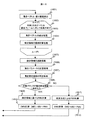
- FIG. 16 is a diagram showing an encoding procedure in the present embodiment. Here, only the inter-screen prediction process (1220) in FIG. 12 is described, and the other operations are the same as those in FIG.
- motion vectors and difference images are calculated (1601).
- the following processing is performed for all the past frames to be processed (1602). That is, integration processing is performed on the motion vector MV of the past frame (1603), and representative coordinates of the integrated region are calculated from the center of gravity of the integrated region, for example (1604). If the coordinate sequence of the integrated region is obtained by the above processing, for example, a block that is close to the target block or the past block corresponding to the target block among the coordinates of the integrated region detected in different frames is the same as the target block. By determining that the block includes an object, integrated region tracking processing is performed (1605).
- the tracking process is a process of determining an integrated area determined to include the same object as the target block for each past frame, and generating a coordinate sequence including representative coordinates of each integrated area.
- a motion modeling parameter is calculated from the coordinate sequence (1606), and by using the parameter, it is determined where the integrated region of the past frame has moved in the target frame, and the motion estimation region in the target frame is specified. (1607). It is determined whether or not the target block is included in the motion estimation region (1608), and if the target block is included in the motion estimation region, the prediction vector PMV is calculated based on the motion vector MV included in the integrated region Then, the difference vector DMV is calculated by calculating the difference from the motion vector MV (1609) (1610). On the other hand, if the target block is not included in the motion estimation region, the prediction vector PMV is calculated by a conventional method such as H.264 (1611), and the difference vector DMV is calculated (1612).
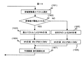
- FIG. 17 is a diagram showing a decoding procedure in the present embodiment. Here, only the inter-screen prediction process (1315) in FIG. 13 is described, and the other operations are the same as those in FIG.
- the following processing is performed for all past frames to be processed (1701). That is, integration processing is performed on the motion vector MV of the past frame (1702), and representative coordinates of the integrated region are calculated from the center of gravity of the integrated region, for example (1703). If the coordinate sequence of the integrated area is obtained by the above processing, for example, among the coordinates of the integrated area detected in different frames, a block that includes the same object as the target block or a block that is close to the past block corresponding to the target block By determining that it is, integrated region tracking processing is performed (1704). Subsequently, a motion modeling parameter is calculated from the coordinate sequence (1705), and the movement estimation region is specified by examining where the integrated region of the past frame has moved in the target frame using the parameter (1706).
- the prediction vector PMV is calculated based on the motion vector MV included in the integrated area Then, the motion vector MV is calculated by calculating the sum with the difference vector DMV (1708) (1709). On the other hand, if the target block is not included in the motion estimation region, the prediction vector PMV is calculated by a conventional method such as H.264 (1710), and the motion vector MV is calculated (1711). Finally, a predicted image and a decoded image are generated based on the calculated motion vector MV (1712). .
- the prediction vector PMV is calculated in units of blocks.
- the prediction vector PMV may be calculated in units of objects separated from the background of the image.
- the present embodiment may be combined with the first and second embodiments.
- the movement of the integrated area is modeled by a mathematical expression. If this operation is performed on the encoding side / decoding side, it is not necessary to encode these motion parameters, so that an increase in code amount can be prevented.
- the prediction vector PMV is calculated using the motion vector MV of the entire screen of the past frame or the entire encoded area of the current frame.
- the fourth embodiment shows a method in which the same effect as the first to third embodiments can be obtained with a small code amount by using only the peripheral blocks in the same frame as the target block.
- FIG. 11 conceptually shows an example of a prediction vector PMV calculation method according to the present invention.
- Encoded blocks adjacent to the left side, upper side, and upper right side of the target block (1101) are block A (1102), block B (1103), and block C (1104), respectively, and the motion vectors in each block are MVA and MVB. And MVC.
- MVX MVX ⁇ MVA, MVB, MVC
- a function Cluster that calculates the reciprocal of the degree that can be integrated with surrounding vectors is set, and this is used to calculate Cluster (MVX).
- the vector having the smallest value is selected (1105).
- each vector MVX (MVX ⁇ MVA, MVB, MVC) that calculates the sum of absolute values of the difference from its surrounding vectors. That is, the encoded blocks adjacent to the left side, the upper side, and the upper right side of the block X (X ⁇ A, B, C) (1107) are the block X1 (1108), the block X2 (1109), and the block X3 (1110), respectively. If the motion vectors in each block are MVX1, MVX2, and MVX3, the function Cluster is expressed as (1111).
- the inner product of the motion vector MVX of the block X (X ⁇ A, B, C) (1107) and the motion vector MVXn of the block X1, X2, X3 is represented by the block X (X ⁇ A, B, C) (1107). May be calculated based on a value obtained by dividing the absolute value of the motion vector by the product of the absolute value of the motion vector of blocks X1, X2, and X3 (1112). However, as long as the similarity between motion vectors is calculated, it is not necessary to follow these mathematical expressions.
- the evaluation value Cluster (BESTMV) based on the selected vector is smaller than the constant Threshold2, it is determined that an object exists around the target block, and the prediction vector PMV is calculated based on the selected vector.
- This calculation method is not particularly limited. For example, it is effective to set the selected vector as it is as the prediction vector PMV (1106).
- the evaluation value Cluster (BESTMV) based on the selected vector is greater than or equal to Threshold2, it is determined that there is no object around the target block, and the prediction vector PMV is calculated in the same procedure as the conventional method such as H.264. (1106).
- the constant Threshold2 may be set to a unique value in advance, or may be freely set on the encoding side and included in the encoded stream. Further, it may be determined dynamically based on encoding information such as a variance value and an average value of the motion vector MV, the size of the integrated region, etc., and it is not necessary to follow this mathematical formula.
- the blocks to which this function is applied are limited to the three types of blocks on the left side, upper side, and upper right side of the target block, but the number of blocks to be applied is not particularly limited. For example, when applied to four types of blocks including the upper left block, the prediction accuracy is further improved.
- FIG. 18 shows an encoding procedure in this embodiment.
- the inter-screen prediction process (1220) in FIG. 12 is described, and the other operations are the same as those in FIG.
- motion vectors and difference images are calculated (1801). Subsequently, among the motion vectors existing around the target block, a vector having the smallest evaluation value Cluster (MVx) indicating similarity to the surrounding motion vector is selected (1802), and the evaluation value Cluster (BESTMV ) And a threshold value are compared (1803). If the evaluation value Cluster (BESTMV) is smaller than the threshold, the selected minimum vector is set as the prediction vector PMV (1804), and the difference vector DMV is calculated by calculating the difference from the motion vector MV (1805). On the other hand, if the evaluation value Cluster (BESTMV) is greater than or equal to the threshold, the prediction vector PMV is calculated by a conventional method such as H.264 (1806), and the difference vector DMV is calculated (1807).
- MVx evaluation value Cluster
- BESTMV evaluation value Cluster
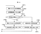
- FIG. 19 shows a decoding procedure in the present embodiment.
- the inter-screen prediction process (1315) in FIG. 13 is described, and the other operations are the same as those in FIG.
- a vector having the smallest evaluation value Cluster (MVx) indicating similarity to the surrounding motion vectors is selected (1901), and the evaluation value Cluster (BESTMV ) And the threshold (1902). If the evaluation value Cluster (BESTMV) is smaller than the threshold value, the selected minimum vector is set as the prediction vector PMV (1903), and the motion vector MV is obtained by calculating the sum with the difference vector DMV (1904). On the other hand, if the evaluation value Cluster (BESTMV) is equal to or greater than the threshold, the prediction vector PMV is calculated by a conventional method such as H.264 (1905), and the motion vector MV is calculated (1906). Finally, a predicted image and a decoded image are generated using the calculated motion vector MV (1907), and the image is decoded.
- MVx evaluation value Cluster
- This example uses only the surrounding blocks in the same frame as the target block. As a result, the same effect as in the first to third embodiments can be obtained with a small amount of code.
- the present invention is useful as a moving picture decoding technique for decoding a moving picture and a moving picture encoding technique for encoding a moving picture.
- 101 to 115 explanatory diagram of a video encoding device according to the present invention
- 201 to 207 explanatory diagram of a video encoding device according to the present invention
- 301 to 308 explanatory diagram of a video decoding device according to the present invention
- 401 to 406 Explanatory diagram of a moving picture decoding apparatus according to the present invention
- 501 to 505 Explanatory diagram of inter-frame prediction encoding processing by H.264 / AVC, 601 to 606...
- Motion vector prediction technology by H.264 / AVC Explanatory diagram, 701 to 706...
- Explanatory diagram relating to a motion vector prediction technique according to the present invention 901 to 911. , 1001 to 1011...
- Explanatory diagrams related to the motion vector prediction technique according to the present invention 1101 to 1112. 1201 to 1219 ... flowchart block, 1301 to 1314 ... flowchart block, 1401 to 1409 ... flowchart block, 1501 to 1509 ... flowchart block, 1601 to 1612 ... flowchart block, 1701 to 1712 ... flowchart Block, 1801 to 1807... Flowchart block, 1901 to 1907... Flowchart block.
Landscapes
- Engineering & Computer Science (AREA)
- Multimedia (AREA)
- Signal Processing (AREA)
- Compression Or Coding Systems Of Tv Signals (AREA)
Abstract
Description
(参考文献1)G. Sullivan and T.Wiegand : “Rate-Distortion Optimization for Video Compression”, IEEE Signal Processing Magazine, vol.15, no.6, pp.74-90, 1998.
続いて、選択された符号化モードに対して、量子化済みの周波数変換係数に逆量子化処理(1216)と逆周波数変換処理(1217)を施して予測差分データを復号化し、復号化画像を生成して(1218)、参照画像メモリに格納する。以上の処理をすべてのブロックに対して完了すれば、画像1フレーム分の符号化は終了する(1219)。
。
Claims (14)
- 画面間予測処理を行う動画像復号化方法であって、
前記画面間予測処理において、
既に復号化された複数のブロックの動きベクトルのうち、類似する動きベクトルを有するブロックを統合して統合領域を算出する統合ステップと、
前記統合領域の動きベクトルを用いて復号化対象ブロックの予測ベクトルを算出する予測ベクトル算出ステップと、
前記予測ベクトルと入力された符号化ストリームに含まれる差分ベクトルとに基づいて、前記対象ブロックの動きベクトルを算出する動きベクトル算出ステップと、
前記動きベクトルを用いて予測画像を生成する予測画像生成ステップと、
前記符号化ストリームに含まれる差分画像と前記予測画像とを加算して復号画像を生成する復号画像生成ステップと
を備えることを特徴とする動画像復号化方法。 - 前記画面間予測処理において、
前記復号化対象ブロックに隣接する統合領域が存在するか否かを判定し、前記隣接する統合領域が存在する場合に、前記統合領域に含まれるブロックの動きベクトル情報を用いて前記予測ベクトルを算出する
ことを特徴とする請求項1に記載の動画像復号化方法。 - 前記画面間予測処理において、
既に復号化した過去フレームにおける統合領域に含まれる動きベクトルに基づいて算出した第一の動きベクトルと前記過去フレームの時刻とに基づいて、前記過去フレームにおける統合領域の復号化対象フレームへの移動先を示す第二の動きベクトルを算出し、前記第二の動きベクトルを用いて前記復号化対象フレームにおける統合領域を算出し、前記統合領域に前記復号化対象ブロックが含まれる場合に、前記第一の動きベクトルに基づいて前記復号化対象ブロックの予測ベクトルを算出する
ことを特徴とする請求項1に記載の動画像復号化方法。 - 前記画面間予測処理において、
既に復号化した複数の過去フレームにおける統合領域のうち一の統合領域に含まれる動きベクトル情報に基づいて、該統合領域における動きベクトルを算出し、符号化ストリームに含まれる動きパラメータを用いて、前記複数の過去フレームにおける統合領域の軌跡を示す関数を算出し、前記関数を用いて復号化対象フレームにおける統合領域を算出し、該統合領域に前記復号化対象ブロックが含まれる場合に、前記統合領域における動きベクトルに基づいて前記復号化対象ブロックの予測ベクトルを算出する
ことを特徴とする請求項1に記載の動画像復号化方法。 - 画面間予測処理を行う動画像復号化方法であって、
前記画面間予測処理において、
復号化対象ブロックに隣接する複数の既に復号化されたブロックの動きベクトルのうちから、前記既に復号化されたブロックにさらに隣接するブロックの動きベクトルと前記既に復号化されたブロックの動きベクトルとの類似性を示す評価値に基づいて、復号化対象ブロックの予測ベクトルを選択する予測ベクトル選択ステップと、
前記予測ベクトルと入力された符号化ストリームに含まれる差分ベクトルとに基づいて、前記復号化対象ブロックの動きベクトルを算出する動きベクトル算出ステップと、
前記動きベクトル算出ステップにおいて算出した動きベクトルを用いて予測画像を生成する予測画像生成ステップと、
前記符号化ストリームに含まれる差分画像と前記予測画像とを加算して復号画像を生成する復号画像生成ステップと
を備えることを特徴とする動画像復号化方法。 - 前記類似性を示す評価値は、
前記復号化対象ブロックに隣接する前記既に復号化されたブロックの動きベクトルと前記既に復号化されたブロックにさらに隣接するブロックの動きベクトルとの差に基づいて算出する
ことを特徴とする請求項5に記載の動画像復号化方法。 - 前記類似性を示す評価値は、
前記復号化対象ブロックに隣接する前記既に復号化されたブロックの動きベクトルと前記既に復号化されたブロックにさらに隣接するブロックの動きベクトルとの内積を、前記既に復号化されたブロックの動きベクトルの絶対値と前記既に復号化されたブロックにさらに隣接するブロックの動きベクトルの絶対値との積で除算した値に基づいて算出する
ことを特徴とする請求項5に記載の動画像復号化方法。 - 画面間予測処理を行う動画像符号化方法であって、
前記画面間予測処理において、
符号化対象ブロックの動きベクトル算出を行う動きベクトル算出ステップと、
既に符号化された複数のブロックの動きベクトルのうち、類似する動きベクトルを有するブロックを統合して統合領域を算出する統合ステップと、
前記統合領域の動きベクトルを用いて符号化対象ブロックの予測ベクトルを算出する予測ベクトル算出ステップと、
前記動きベクトル算出ステップで算出した前記動きベクトルと前記予測ベクトルとの差分ベクトルを算出する差分ベクトル算出ステップと
を備えることを特徴とする動画像符号化方法。 - 前記画面間予測処理において、
前記符号化対象ブロックに隣接する統合領域が存在するか否かを判定し、前記隣接する統合領域が存在する場合に、前記統合領域に含まれるブロックの動きベクトル情報を用いて前記予測ベクトルを算出する
ことを特徴とする請求項8に記載の動画像符号化方法。 - 前記画面間予測処理において、
既に符号化した過去フレームにおける統合領域に含まれる動きベクトルに基づいて算出した第一の動きベクトルと前記過去フレームの時刻とに基づいて、前記過去フレームにおける統合領域の符号化対象フレーム中の移動先を示す第二の動きベクトルを算出し、前記第二の動きベクトルを用いて前記符号化対象フレームにおける統合領域を算出し、該統合領域に前記符号化対象ブロックが含まれる場合に、前記第一の動きベクトルに基づいて前記符号化対象ブロックの予測ベクトルを算出する
ことを特徴とする請求項8に記載の動画像符号化方法。 - 前記画面間予測処理において、
複数の過去フレームにおける統合領域の座標から、前記複数の過去フレームにおける前記統合領域の座標列を示す関数を算出し、前記関数を用いて符号化対象フレームにおける統合領域を算出し、該統合領域に前記符号化対象ブロックが含まれる場合に、既に符号化した過去フレームにおける統合領域のうち一の統合領域に含まれる動きベクトルに基づいて算出した動きベクトルに基づいて前記符号化対象ブロックの予測ベクトルを算出する
ことを特徴とする請求項8に記載の動画像符号化方法。 - 画面間予測処理を行う動画像符号化方法であって、
前記画面間予測処理において、
符号化対象ブロックの動きベクトル算出を行う動きベクトル算出ストップと、
前記符号化対象ブロックに隣接する複数の既に符号化されたブロックの動きベクトルのうちから、前記既に符号化されたブロックにさらに隣接するブロックの動きベクトルと前記既に符号化されたブロックの動きベクトルとの類似性を示す評価値に基づいて、前記符号化対象ブロックの予測ベクトルを選択する予測ベクトル算出ステップと、
前記動きベクトル算出ステップで算出した前記動きベクトルと前記予測ベクトルとの差分ベクトルを算出する差分ベクトル算出ステップと
を備えることを特徴とする動画像符号化方法。 - 前記類似性を示す評価値は、
前記符号化対象ブロックに隣接する前記既に符号化されたブロックの動きベクトルと前記既に符号化されたブロックにさらに隣接するブロックの動きベクトルとの差に基づいて算出する
ことを特徴とする請求項12に記載の動画像符号化方法。 - 前記類似性を示す評価値は、
前記符号化対象ブロックに隣接する前記既に符号化されたブロックの動きベクトルと前記既に符号化されたブロックにさらに隣接するブロックの動きベクトルとの内積を、前記既に符号化されたブロックの動きベクトルの絶対値と前記既に符号化されたブロックにさらに隣接するブロックの動きベクトルの絶対値との積で除算した値に基づいて算出する
ことを特徴とする請求項12に記載の動画像符号化方法。
Priority Applications (8)
| Application Number | Priority Date | Filing Date | Title |
|---|---|---|---|
| US13/132,426 US9560368B2 (en) | 2008-12-03 | 2009-11-27 | Moving picture decoding method and moving picture encoding method |
| JP2010541217A JP5277257B2 (ja) | 2008-12-03 | 2009-11-27 | 動画像復号化方法および動画像符号化方法 |
| CN2009801485242A CN102239693B (zh) | 2008-12-03 | 2009-11-27 | 运动图像解码方法和运动图像编码方法 |
| US15/383,421 US9906808B2 (en) | 2008-12-03 | 2016-12-19 | Moving picture decoding method and moving picture encoding method |
| US15/874,955 US10382775B2 (en) | 2008-12-03 | 2018-01-19 | Moving picture decoding method and moving picture encoding method |
| US16/447,167 US10764599B2 (en) | 2008-12-03 | 2019-06-20 | Moving picture decoding method and moving picture encoding method |
| US16/934,480 US11134263B2 (en) | 2008-12-03 | 2020-07-21 | Moving picture decoding method and moving picture encoding method |
| US17/409,867 US11546627B2 (en) | 2008-12-03 | 2021-08-24 | Moving picture decoding method and moving picture encoding method |
Applications Claiming Priority (2)
| Application Number | Priority Date | Filing Date | Title |
|---|---|---|---|
| JP2008308113 | 2008-12-03 | ||
| JP2008-308113 | 2008-12-03 |
Related Child Applications (2)
| Application Number | Title | Priority Date | Filing Date |
|---|---|---|---|
| US13/132,426 A-371-Of-International US9560368B2 (en) | 2008-12-03 | 2009-11-27 | Moving picture decoding method and moving picture encoding method |
| US15/383,421 Continuation US9906808B2 (en) | 2008-12-03 | 2016-12-19 | Moving picture decoding method and moving picture encoding method |
Publications (1)
| Publication Number | Publication Date |
|---|---|
| WO2010064396A1 true WO2010064396A1 (ja) | 2010-06-10 |
Family
ID=42233054
Family Applications (1)
| Application Number | Title | Priority Date | Filing Date |
|---|---|---|---|
| PCT/JP2009/006438 WO2010064396A1 (ja) | 2008-12-03 | 2009-11-27 | 動画像復号化方法および動画像符号化方法 |
Country Status (4)
| Country | Link |
|---|---|
| US (6) | US9560368B2 (ja) |
| JP (1) | JP5277257B2 (ja) |
| CN (2) | CN102239693B (ja) |
| WO (1) | WO2010064396A1 (ja) |
Cited By (14)
| Publication number | Priority date | Publication date | Assignee | Title |
|---|---|---|---|---|
| WO2012011432A1 (ja) * | 2010-07-20 | 2012-01-26 | 株式会社エヌ・ティ・ティ・ドコモ | 画像予測符号化装置、画像予測符号化方法、画像予測符号化プログラム、画像予測復号装置、画像予測復号方法、及び、画像予測復号プログラム |
| WO2012043541A1 (ja) * | 2010-09-30 | 2012-04-05 | シャープ株式会社 | 予測ベクトル生成方法、画像符号化方法、画像復号方法、予測ベクトル生成装置、画像符号化装置、画像復号装置、予測ベクトル生成プログラム、画像符号化プログラムおよび画像復号プログラム |
| WO2012056924A1 (ja) * | 2010-10-25 | 2012-05-03 | ソニー株式会社 | 画像処理装置と画像処理方法 |
| WO2012086461A1 (ja) * | 2010-12-20 | 2012-06-28 | ソニー株式会社 | 画像処理装置および方法 |
| WO2012090397A1 (ja) * | 2010-12-28 | 2012-07-05 | 株式会社Jvcケンウッド | 動画像符号化装置、動画像符号化方法及び動画像符号化プログラム、並びに動画像復号装置、動画像復号方法及び動画像復号プログラム |
| WO2012128068A1 (ja) * | 2011-03-18 | 2012-09-27 | ソニー株式会社 | 画像処理装置、画像処理方法、及び、プログラム |
| WO2012153440A1 (ja) * | 2011-05-09 | 2012-11-15 | シャープ株式会社 | 予測ベクトル生成方法、予測ベクトル生成装置、予測ベクトル生成プログラム、画像符号化方法、画像符号化装置、画像符号化プログラム、画像復号方法、画像復号装置、及び画像復号プログラム |
| JPWO2011046008A1 (ja) * | 2009-10-16 | 2013-03-04 | シャープ株式会社 | 動画像符号化装置、および、動画像復号装置 |
| JP2014150307A (ja) * | 2013-01-31 | 2014-08-21 | Kddi Corp | 映像圧縮フォーマット変換装置、映像圧縮フォーマット変換方法、およびプログラム |
| AU2015252039B2 (en) * | 2010-07-20 | 2016-09-01 | Ntt Docomo, Inc. | Image prediction encoding device, image prediction encoding method, image prediction encoding program, image prediction decoding device, image prediction decoding method, and image prediction decoding program |
| TWI597972B (zh) * | 2011-12-28 | 2017-09-01 | Jvc Kenwood Corp | Motion picture encoding apparatus, motion picture encoding method, and recording medium for moving picture encoding program |
| RU2643476C2 (ru) * | 2010-12-23 | 2018-02-01 | Самсунг Электроникс Ко., Лтд. | Способ и устройство кодирования режима внутрикадрового предсказания для блока предсказания изображений и способ и устройство декодирования режима внутрикадрового предсказания для блока предсказания изображений |
| US10063855B2 (en) | 2009-03-23 | 2018-08-28 | Ntt Docomo, Inc. | Image predictive encoding and decoding device |
| JP2018139416A (ja) * | 2011-04-27 | 2018-09-06 | 株式会社Jvcケンウッド | 動画像符号化装置、動画像符号化方法、及び動画像符号化プログラム、並びに、動画像復号装置、動画像復号方法、及び動画像復号プログラム |
Families Citing this family (10)
| Publication number | Priority date | Publication date | Assignee | Title |
|---|---|---|---|---|
| KR101619972B1 (ko) * | 2008-10-02 | 2016-05-11 | 한국전자통신연구원 | 이산 여현 변환/이산 정현 변환을 선택적으로 이용하는 부호화/복호화 장치 및 방법 |
| JP5368631B2 (ja) * | 2010-04-08 | 2013-12-18 | 株式会社東芝 | 画像符号化方法、装置、及びプログラム |
| US8885701B2 (en) * | 2010-09-08 | 2014-11-11 | Samsung Electronics Co., Ltd. | Low complexity transform coding using adaptive DCT/DST for intra-prediction |
| JP2012151576A (ja) | 2011-01-18 | 2012-08-09 | Hitachi Ltd | 画像符号化方法、画像符号化装置、画像復号方法及び画像復号装置 |
| WO2012124121A1 (ja) * | 2011-03-17 | 2012-09-20 | 富士通株式会社 | 動画像復号方法、動画像符号化方法、動画像復号装置及び動画像復号プログラム |
| CN104539929B (zh) * | 2015-01-20 | 2016-12-07 | 深圳威阿科技有限公司 | 带有运动预测的立体图像编码方法和编码装置 |
| CN106254878B (zh) | 2015-06-14 | 2020-06-12 | 同济大学 | 一种图像编码及解码方法、图像处理设备 |
| WO2016202189A1 (zh) * | 2015-06-14 | 2016-12-22 | 同济大学 | 图像编码及解码方法、图像处理设备、计算机存储介质 |
| CN107770540B (zh) * | 2016-08-21 | 2024-01-09 | 上海天荷电子信息有限公司 | 融合多种具有不同参考关系的基元的数据压缩方法和装置 |
| CN112203091B (zh) * | 2020-12-04 | 2021-05-04 | 浙江智慧视频安防创新中心有限公司 | 基于二次多项式的运动矢量预测方法、系统及计算机介质 |
Citations (5)
| Publication number | Priority date | Publication date | Assignee | Title |
|---|---|---|---|---|
| JP2005124001A (ja) * | 2003-10-17 | 2005-05-12 | Ntt Docomo Inc | 動画像符号化装置、動画像符号化方法、動画像符号化プログラム、動画像復号装置、動画像復号方法、及び動画像復号プログラム |
| JP2007110672A (ja) * | 2005-09-14 | 2007-04-26 | Sanyo Electric Co Ltd | 符号化方法 |
| JP2007300209A (ja) * | 2006-04-27 | 2007-11-15 | Pioneer Electronic Corp | 動画像再符号化装置およびその動きベクトル判定方法 |
| JP2008278091A (ja) * | 2007-04-27 | 2008-11-13 | Hitachi Ltd | 動画像記録方法及びその装置 |
| JP2008283490A (ja) * | 2007-05-10 | 2008-11-20 | Ntt Docomo Inc | 動画像符号化装置、方法及びプログラム、並びに動画像復号化装置、方法及びプログラム |
Family Cites Families (16)
| Publication number | Priority date | Publication date | Assignee | Title |
|---|---|---|---|---|
| JPH09261648A (ja) * | 1996-03-21 | 1997-10-03 | Fujitsu Ltd | シーンチェンジ検出装置 |
| JP4142180B2 (ja) * | 1998-10-29 | 2008-08-27 | 富士通株式会社 | 動きベクトル符号化装置および復号装置 |
| KR100833228B1 (ko) * | 2002-02-21 | 2008-05-28 | 삼성전자주식회사 | 고정 연산량을 갖는 동영상 부호화 방법 및 그 장치 |
| KR100865034B1 (ko) * | 2002-07-18 | 2008-10-23 | 엘지전자 주식회사 | 모션 벡터 예측 방법 |
| US20040081238A1 (en) * | 2002-10-25 | 2004-04-29 | Manindra Parhy | Asymmetric block shape modes for motion estimation |
| JP4373702B2 (ja) * | 2003-05-07 | 2009-11-25 | 株式会社エヌ・ティ・ティ・ドコモ | 動画像符号化装置、動画像復号化装置、動画像符号化方法、動画像復号化方法、動画像符号化プログラム及び動画像復号化プログラム |
| US20050013498A1 (en) * | 2003-07-18 | 2005-01-20 | Microsoft Corporation | Coding of motion vector information |
| US7366237B2 (en) * | 2003-09-09 | 2008-04-29 | Microsoft Corporation | Low complexity real-time video coding |
| US7822116B2 (en) * | 2005-04-14 | 2010-10-26 | Broadcom Corporation | Method and system for rate estimation in a video encoder |
| CN1322758C (zh) * | 2005-06-09 | 2007-06-20 | 上海交通大学 | 基于对象的纹理快速运动估值的方法 |
| CN100473168C (zh) * | 2005-06-21 | 2009-03-25 | 中国科学院计算技术研究所 | 视频编码的运动矢量空间预测方法 |
| US20080123947A1 (en) * | 2005-07-22 | 2008-05-29 | Mitsubishi Electric Corporation | Image encoding device, image decoding device, image encoding method, image decoding method, image encoding program, image decoding program, computer readable recording medium having image encoding program recorded therein |
| US20070064809A1 (en) | 2005-09-14 | 2007-03-22 | Tsuyoshi Watanabe | Coding method for coding moving images |
| US8879856B2 (en) * | 2005-09-27 | 2014-11-04 | Qualcomm Incorporated | Content driven transcoder that orchestrates multimedia transcoding using content information |
| JP4879558B2 (ja) * | 2005-11-02 | 2012-02-22 | パナソニック株式会社 | 動きベクトル検出装置 |
| US8204124B2 (en) * | 2007-08-27 | 2012-06-19 | Sony Corporation | Image processing apparatus, method thereof, and program |
-
2009
- 2009-11-27 JP JP2010541217A patent/JP5277257B2/ja active Active
- 2009-11-27 US US13/132,426 patent/US9560368B2/en active Active
- 2009-11-27 CN CN2009801485242A patent/CN102239693B/zh active Active
- 2009-11-27 WO PCT/JP2009/006438 patent/WO2010064396A1/ja active Application Filing
- 2009-11-27 CN CN201310591426.4A patent/CN103647972B/zh active Active
-
2016
- 2016-12-19 US US15/383,421 patent/US9906808B2/en active Active
-
2018
- 2018-01-19 US US15/874,955 patent/US10382775B2/en active Active
-
2019
- 2019-06-20 US US16/447,167 patent/US10764599B2/en active Active
-
2020
- 2020-07-21 US US16/934,480 patent/US11134263B2/en active Active
-
2021
- 2021-08-24 US US17/409,867 patent/US11546627B2/en active Active
Patent Citations (5)
| Publication number | Priority date | Publication date | Assignee | Title |
|---|---|---|---|---|
| JP2005124001A (ja) * | 2003-10-17 | 2005-05-12 | Ntt Docomo Inc | 動画像符号化装置、動画像符号化方法、動画像符号化プログラム、動画像復号装置、動画像復号方法、及び動画像復号プログラム |
| JP2007110672A (ja) * | 2005-09-14 | 2007-04-26 | Sanyo Electric Co Ltd | 符号化方法 |
| JP2007300209A (ja) * | 2006-04-27 | 2007-11-15 | Pioneer Electronic Corp | 動画像再符号化装置およびその動きベクトル判定方法 |
| JP2008278091A (ja) * | 2007-04-27 | 2008-11-13 | Hitachi Ltd | 動画像記録方法及びその装置 |
| JP2008283490A (ja) * | 2007-05-10 | 2008-11-20 | Ntt Docomo Inc | 動画像符号化装置、方法及びプログラム、並びに動画像復号化装置、方法及びプログラム |
Cited By (50)
| Publication number | Priority date | Publication date | Assignee | Title |
|---|---|---|---|---|
| US10284848B2 (en) | 2009-03-23 | 2019-05-07 | Ntt Docomo, Inc. | Image predictive encoding and decoding device |
| US10284846B2 (en) | 2009-03-23 | 2019-05-07 | Ntt Docomo, Inc. | Image predictive encoding and decoding device |
| US10284847B2 (en) | 2009-03-23 | 2019-05-07 | Ntt Docomo, Inc. | Image predictive encoding and decoding device |
| US10063855B2 (en) | 2009-03-23 | 2018-08-28 | Ntt Docomo, Inc. | Image predictive encoding and decoding device |
| JPWO2011046008A1 (ja) * | 2009-10-16 | 2013-03-04 | シャープ株式会社 | 動画像符号化装置、および、動画像復号装置 |
| US10225580B2 (en) | 2010-07-20 | 2019-03-05 | Ntt Docomo, Inc. | Image prediction encoding/decoding system |
| US9497480B2 (en) | 2010-07-20 | 2016-11-15 | Ntt Docomo, Inc. | Image prediction encoding/decoding system |
| RU2667716C1 (ru) * | 2010-07-20 | 2018-09-24 | Нтт Докомо, Инк. | Устройство кодирования изображений с предсказанием, способ кодирования изображений с предсказанием, программа кодирования изображений с предсказанием, устройство декодирования изображений с предсказанием, способ декодирования изображений с предсказанием и программа декодирования изображений с предсказанием |
| US9986261B2 (en) | 2010-07-20 | 2018-05-29 | Ntt Docomo, Inc. | Image prediction encoding/decoding system |
| RU2658798C1 (ru) * | 2010-07-20 | 2018-06-22 | Нтт Докомо, Инк. | Устройство кодирования изображений с предсказанием, способ кодирования изображений с предсказанием, программа кодирования изображений с предсказанием, устройство декодирования изображений с предсказанием, способ декодирования изображений с предсказанием и программа декодирования изображений с предсказанием |
| WO2012011432A1 (ja) * | 2010-07-20 | 2012-01-26 | 株式会社エヌ・ティ・ティ・ドコモ | 画像予測符号化装置、画像予測符号化方法、画像予測符号化プログラム、画像予測復号装置、画像予測復号方法、及び、画像予測復号プログラム |
| US10542287B2 (en) | 2010-07-20 | 2020-01-21 | Ntt Docomo, Inc. | Image prediction encoding/decoding system |
| TWI469646B (zh) * | 2010-07-20 | 2015-01-11 | Ntt Docomo Inc | Image predictive coding apparatus, image predictive coding method, image predictive coding program, image predictive decoding apparatus, image predictive decoding method, and image predictive decoding program |
| JP5661114B2 (ja) * | 2010-07-20 | 2015-01-28 | 株式会社Nttドコモ | 画像予測符号化装置、画像予測符号化方法、画像予測符号化プログラム、画像予測復号装置、画像予測復号方法、及び、画像予測復号プログラム |
| JP2015065690A (ja) * | 2010-07-20 | 2015-04-09 | 株式会社Nttドコモ | 画像予測符号化装置、画像予測符号化方法、画像予測符号化プログラム、画像予測復号装置、画像予測復号方法、及び、画像予測復号プログラム |
| AU2011280629B2 (en) * | 2010-07-20 | 2015-08-06 | Ntt Docomo, Inc. | Image prediction encoding device, image prediction encoding method, image prediction encoding program, image prediction decoding device, image prediction decoding method, and image prediction decoding program |
| US9185409B2 (en) | 2010-07-20 | 2015-11-10 | Ntt Docomo, Inc. | Image prediction encoding/decoding system |
| US10063888B1 (en) | 2010-07-20 | 2018-08-28 | Ntt Docomo, Inc. | Image prediction encoding/decoding system |
| CN105898326A (zh) * | 2010-07-20 | 2016-08-24 | 株式会社Ntt都科摩 | 图像预测解码装置和图像预测解码方法 |
| AU2015252039B2 (en) * | 2010-07-20 | 2016-09-01 | Ntt Docomo, Inc. | Image prediction encoding device, image prediction encoding method, image prediction encoding program, image prediction decoding device, image prediction decoding method, and image prediction decoding program |
| CN105898326B (zh) * | 2010-07-20 | 2019-01-29 | 株式会社Ntt都科摩 | 图像预测解码装置和图像预测解码方法 |
| RU2619202C1 (ru) * | 2010-07-20 | 2017-05-12 | Нтт Докомо, Инк. | Устройство кодирования изображений с предсказанием, способ кодирования изображений с предсказанием, программа кодирования изображений с предсказанием, устройство декодирования изображений с предсказанием, способ декодирования изображений с предсказанием и программа декодирования изображений с предсказанием |
| US10230987B2 (en) | 2010-07-20 | 2019-03-12 | Ntt Docomo, Inc. | Image prediction encoding/decoding system |
| RU2685393C1 (ru) * | 2010-07-20 | 2019-04-17 | Нтт Докомо, Инк. | Устройство кодирования изображений с предсказанием, способ кодирования изображений с предсказанием, программа кодирования изображений с предсказанием, устройство декодирования изображений с предсказанием, способ декодирования изображений с предсказанием и программа декодирования изображений с предсказанием |
| US9794592B2 (en) | 2010-07-20 | 2017-10-17 | Ntt Docomo, Inc. | Image prediction encoding/decoding system |
| RU2685390C1 (ru) * | 2010-07-20 | 2019-04-17 | Нтт Докомо, Инк. | Устройство кодирования изображений с предсказанием, способ кодирования изображений с предсказанием, программа кодирования изображений с предсказанием, устройство декодирования изображений с предсказанием, способ декодирования изображений с предсказанием и программа декодирования изображений с предсказанием |
| RU2685389C1 (ru) * | 2010-07-20 | 2019-04-17 | Нтт Докомо, Инк. | Устройство кодирования изображений с предсказанием, способ кодирования изображений с предсказанием, программа кодирования изображений с предсказанием, устройство декодирования изображений с предсказанием, способ декодирования изображений с предсказанием и программа декодирования изображений с предсказанием |
| RU2685388C1 (ru) * | 2010-07-20 | 2019-04-17 | Нтт Докомо, Инк. | Устройство кодирования изображений с предсказанием, способ кодирования изображений с предсказанием, программа кодирования изображений с предсказанием, устройство декодирования изображений с предсказанием, способ декодирования изображений с предсказанием и программа декодирования изображений с предсказанием |
| JP2012080242A (ja) * | 2010-09-30 | 2012-04-19 | Sharp Corp | 予測ベクトル生成方法、画像符号化方法、画像復号方法、予測ベクトル生成装置、画像符号化装置、画像復号装置、予測ベクトル生成プログラム、画像符号化プログラムおよび画像復号プログラム |
| WO2012043541A1 (ja) * | 2010-09-30 | 2012-04-05 | シャープ株式会社 | 予測ベクトル生成方法、画像符号化方法、画像復号方法、予測ベクトル生成装置、画像符号化装置、画像復号装置、予測ベクトル生成プログラム、画像符号化プログラムおよび画像復号プログラム |
| WO2012056924A1 (ja) * | 2010-10-25 | 2012-05-03 | ソニー株式会社 | 画像処理装置と画像処理方法 |
| CN103168471A (zh) * | 2010-10-25 | 2013-06-19 | 索尼公司 | 图像处理装置和图像处理方法 |
| WO2012086461A1 (ja) * | 2010-12-20 | 2012-06-28 | ソニー株式会社 | 画像処理装置および方法 |
| JP2012209911A (ja) * | 2010-12-20 | 2012-10-25 | Sony Corp | 画像処理装置および方法 |
| US11070811B2 (en) | 2010-12-23 | 2021-07-20 | Samsung Electronics Co., Ltd. | Method and device for encoding intra prediction mode for image prediction unit, and method and device for decoding intra prediction mode for image prediction unit |
| US10630986B2 (en) | 2010-12-23 | 2020-04-21 | Samsung Electronics Co., Ltd. | Method and device for encoding intra prediction mode for image prediction unit, and method and device for decoding intra prediction mode for image prediction unit |
| RU2676234C1 (ru) * | 2010-12-23 | 2018-12-26 | Самсунг Электроникс Ко., Лтд. | Способ и устройство кодирования режима внутрикадрового предсказания для блока предсказания изображений и способ и устройство декодирования режима внутрикадрового предсказания для блока предсказания изображений |
| US11509899B2 (en) | 2010-12-23 | 2022-11-22 | Samsung Electronics Co., Ltd. | Method and device for encoding intra prediction mode for image prediction unit, and method and device for decoding intra prediction mode for image prediction unit |
| RU2643476C2 (ru) * | 2010-12-23 | 2018-02-01 | Самсунг Электроникс Ко., Лтд. | Способ и устройство кодирования режима внутрикадрового предсказания для блока предсказания изображений и способ и устройство декодирования режима внутрикадрового предсказания для блока предсказания изображений |
| US10021384B2 (en) | 2010-12-23 | 2018-07-10 | Samsung Electronics Co., Ltd. | Method and device for encoding intra prediction mode for image prediction unit, and method and device for decoding intra prediction mode for image prediction unit |
| RU2697628C1 (ru) * | 2010-12-23 | 2019-08-15 | Самсунг Электроникс Ко., Лтд. | Способ и устройство кодирования режима внутрикадрового предсказания для блока предсказания изображений и способ и устройство декодирования режима внутрикадрового предсказания для блока предсказания изображений |
| WO2012090397A1 (ja) * | 2010-12-28 | 2012-07-05 | 株式会社Jvcケンウッド | 動画像符号化装置、動画像符号化方法及び動画像符号化プログラム、並びに動画像復号装置、動画像復号方法及び動画像復号プログラム |
| WO2012128068A1 (ja) * | 2011-03-18 | 2012-09-27 | ソニー株式会社 | 画像処理装置、画像処理方法、及び、プログラム |
| JP6061150B2 (ja) * | 2011-03-18 | 2017-01-18 | ソニー株式会社 | 画像処理装置、画像処理方法、及び、プログラム |
| US9363500B2 (en) | 2011-03-18 | 2016-06-07 | Sony Corporation | Image processing device, image processing method, and program |
| JP2018139416A (ja) * | 2011-04-27 | 2018-09-06 | 株式会社Jvcケンウッド | 動画像符号化装置、動画像符号化方法、及び動画像符号化プログラム、並びに、動画像復号装置、動画像復号方法、及び動画像復号プログラム |
| WO2012153440A1 (ja) * | 2011-05-09 | 2012-11-15 | シャープ株式会社 | 予測ベクトル生成方法、予測ベクトル生成装置、予測ベクトル生成プログラム、画像符号化方法、画像符号化装置、画像符号化プログラム、画像復号方法、画像復号装置、及び画像復号プログラム |
| TWI597972B (zh) * | 2011-12-28 | 2017-09-01 | Jvc Kenwood Corp | Motion picture encoding apparatus, motion picture encoding method, and recording medium for moving picture encoding program |
| TWI616091B (zh) * | 2011-12-28 | 2018-02-21 | Jvc Kenwood Corp | 動態影像解碼裝置、動態影像解碼方法、及儲存有動態影像解碼程式之記錄媒體 |
| JP2014150307A (ja) * | 2013-01-31 | 2014-08-21 | Kddi Corp | 映像圧縮フォーマット変換装置、映像圧縮フォーマット変換方法、およびプログラム |
Also Published As
| Publication number | Publication date |
|---|---|
| CN103647972B (zh) | 2017-04-12 |
| JP5277257B2 (ja) | 2013-08-28 |
| US11546627B2 (en) | 2023-01-03 |
| CN102239693A (zh) | 2011-11-09 |
| US20180146210A1 (en) | 2018-05-24 |
| US20170099497A1 (en) | 2017-04-06 |
| US9906808B2 (en) | 2018-02-27 |
| US10382775B2 (en) | 2019-08-13 |
| US20110249749A1 (en) | 2011-10-13 |
| US9560368B2 (en) | 2017-01-31 |
| US10764599B2 (en) | 2020-09-01 |
| JPWO2010064396A1 (ja) | 2012-05-10 |
| CN103647972A (zh) | 2014-03-19 |
| US11134263B2 (en) | 2021-09-28 |
| US20210385486A1 (en) | 2021-12-09 |
| CN102239693B (zh) | 2013-12-18 |
| US20190306529A1 (en) | 2019-10-03 |
| US20200351516A1 (en) | 2020-11-05 |
Similar Documents
| Publication | Publication Date | Title |
|---|---|---|
| US11546627B2 (en) | Moving picture decoding method and moving picture encoding method | |
| US20230353778A1 (en) | Motion vector refinement for multi-reference prediction | |
| JP5669278B2 (ja) | 画像シーケンスのブロックを符号化する方法およびこのブロックを再構成する方法 | |
| JP5061179B2 (ja) | 照明変化補償動き予測符号化および復号化方法とその装置 | |
| JP5216710B2 (ja) | 復号化処理方法 | |
| KR20110008653A (ko) | 움직임 벡터 예측 방법과 이를 이용한 영상 부호화/복호화 장치 및 방법 | |
| WO2011099468A1 (ja) | 動きベクトル予測符号化方法,動きベクトル予測復号方法,動画像符号化装置,動画像復号装置およびそれらのプログラム | |
| KR20090095012A (ko) | 연속적인 움직임 추정을 이용한 영상 부호화, 복호화 방법및 장치 | |
| JP5367097B2 (ja) | 動きベクトル予測符号化方法、動きベクトル予測復号方法、動画像符号化装置、動画像復号装置およびそれらのプログラム | |
| JP2011199362A (ja) | 動画像符号化装置、動画像符号化方法及び動画像復号装置ならびに動画像復号方法 | |
| JP2016154395A (ja) | 以前ブロックの動きベクトルを現在ブロックの動きベクトルとして用いる映像符号化/復号化方法及び装置 | |
| WO2012121234A1 (ja) | 映像符号化装置、映像符号化方法および映像符号化プログラム | |
| JP6019797B2 (ja) | 動画像符号化装置、動画像符号化方法、及びプログラム | |
| WO2019150411A1 (ja) | 映像符号化装置、映像符号化方法、映像復号装置、映像復号方法、及び映像符号化システム | |
| JP5281597B2 (ja) | 動きベクトル予測方法,動きベクトル予測装置および動きベクトル予測プログラム | |
| JP2013121044A (ja) | 画像符号化装置及び画像符号化方法 | |
| JP5281596B2 (ja) | 動きベクトル予測方法,動きベクトル予測装置および動きベクトル予測プログラム | |
| WO2010061515A1 (ja) | 動画像符号化装置及び符号化方法、動画像復号化装置及び復号化方法 | |
| JP2004165785A (ja) | 画像符号化方法,画像復号方法,画像符号化装置,画像復号装置,画像符号化プログラム,画像復号プログラムおよびそのプログラムを記録した記録媒体 | |
| WO2009128208A1 (ja) | 動画像符号化装置、動画像復号化装置、動画像符号化方法、および動画像復号化方法 | |
| KR20130105402A (ko) | 추가의 비트 레이트 오버헤드 없이 참조 블록의 로컬 조명 및 콘트라스트 보상에 기초한 멀티 뷰 비디오 코딩 및 디코딩 방법 | |
| JP2013517733A (ja) | 以前ブロックの動きベクトルを現在ブロックの動きベクトルとして用いる映像符号化/復号化方法及び装置 | |
| US20140376628A1 (en) | Multi-view image encoding device and method, and multi-view image decoding device and method | |
| JP2012095099A (ja) | 動画像符号化装置、動画像符号化方法及び動画像符号化プログラム、並びに動画像復号装置、動画像復号方法及び動画像復号プログラム |
Legal Events
| Date | Code | Title | Description |
|---|---|---|---|
| WWE | Wipo information: entry into national phase |
Ref document number: 200980148524.2 Country of ref document: CN |
|
| 121 | Ep: the epo has been informed by wipo that ep was designated in this application |
Ref document number: 09830166 Country of ref document: EP Kind code of ref document: A1 |
|
| ENP | Entry into the national phase |
Ref document number: 2010541217 Country of ref document: JP Kind code of ref document: A |
|
| NENP | Non-entry into the national phase |
Ref country code: DE |
|
| WWE | Wipo information: entry into national phase |
Ref document number: 13132426 Country of ref document: US |
|
| 122 | Ep: pct application non-entry in european phase |
Ref document number: 09830166 Country of ref document: EP Kind code of ref document: A1 |