WO2010064363A1 - Vehicle running control device - Google Patents
Vehicle running control device Download PDFInfo
- Publication number
- WO2010064363A1 WO2010064363A1 PCT/JP2009/006039 JP2009006039W WO2010064363A1 WO 2010064363 A1 WO2010064363 A1 WO 2010064363A1 JP 2009006039 W JP2009006039 W JP 2009006039W WO 2010064363 A1 WO2010064363 A1 WO 2010064363A1
- Authority
- WO
- WIPO (PCT)
- Prior art keywords
- vehicle speed
- driving force
- target
- mode
- upper limit
- Prior art date
Links
Images


Classifications
-
- F—MECHANICAL ENGINEERING; LIGHTING; HEATING; WEAPONS; BLASTING
- F02—COMBUSTION ENGINES; HOT-GAS OR COMBUSTION-PRODUCT ENGINE PLANTS
- F02D—CONTROLLING COMBUSTION ENGINES
- F02D29/00—Controlling engines, such controlling being peculiar to the devices driven thereby, the devices being other than parts or accessories essential to engine operation, e.g. controlling of engines by signals external thereto
- F02D29/02—Controlling engines, such controlling being peculiar to the devices driven thereby, the devices being other than parts or accessories essential to engine operation, e.g. controlling of engines by signals external thereto peculiar to engines driving vehicles; peculiar to engines driving variable pitch propellers
-
- B—PERFORMING OPERATIONS; TRANSPORTING
- B60—VEHICLES IN GENERAL
- B60W—CONJOINT CONTROL OF VEHICLE SUB-UNITS OF DIFFERENT TYPE OR DIFFERENT FUNCTION; CONTROL SYSTEMS SPECIALLY ADAPTED FOR HYBRID VEHICLES; ROAD VEHICLE DRIVE CONTROL SYSTEMS FOR PURPOSES NOT RELATED TO THE CONTROL OF A PARTICULAR SUB-UNIT
- B60W30/00—Purposes of road vehicle drive control systems not related to the control of a particular sub-unit, e.g. of systems using conjoint control of vehicle sub-units, or advanced driver assistance systems for ensuring comfort, stability and safety or drive control systems for propelling or retarding the vehicle
- B60W30/14—Adaptive cruise control
- B60W30/143—Speed control
-
- B—PERFORMING OPERATIONS; TRANSPORTING
- B60—VEHICLES IN GENERAL
- B60W—CONJOINT CONTROL OF VEHICLE SUB-UNITS OF DIFFERENT TYPE OR DIFFERENT FUNCTION; CONTROL SYSTEMS SPECIALLY ADAPTED FOR HYBRID VEHICLES; ROAD VEHICLE DRIVE CONTROL SYSTEMS FOR PURPOSES NOT RELATED TO THE CONTROL OF A PARTICULAR SUB-UNIT
- B60W2552/00—Input parameters relating to infrastructure
- B60W2552/15—Road slope
-
- B—PERFORMING OPERATIONS; TRANSPORTING
- B60—VEHICLES IN GENERAL
- B60W—CONJOINT CONTROL OF VEHICLE SUB-UNITS OF DIFFERENT TYPE OR DIFFERENT FUNCTION; CONTROL SYSTEMS SPECIALLY ADAPTED FOR HYBRID VEHICLES; ROAD VEHICLE DRIVE CONTROL SYSTEMS FOR PURPOSES NOT RELATED TO THE CONTROL OF A PARTICULAR SUB-UNIT
- B60W2710/00—Output or target parameters relating to a particular sub-units
- B60W2710/10—Change speed gearings
- B60W2710/1061—Output power
-
- B—PERFORMING OPERATIONS; TRANSPORTING
- B60—VEHICLES IN GENERAL
- B60W—CONJOINT CONTROL OF VEHICLE SUB-UNITS OF DIFFERENT TYPE OR DIFFERENT FUNCTION; CONTROL SYSTEMS SPECIALLY ADAPTED FOR HYBRID VEHICLES; ROAD VEHICLE DRIVE CONTROL SYSTEMS FOR PURPOSES NOT RELATED TO THE CONTROL OF A PARTICULAR SUB-UNIT
- B60W2720/00—Output or target parameters relating to overall vehicle dynamics
- B60W2720/10—Longitudinal speed
-
- Y—GENERAL TAGGING OF NEW TECHNOLOGICAL DEVELOPMENTS; GENERAL TAGGING OF CROSS-SECTIONAL TECHNOLOGIES SPANNING OVER SEVERAL SECTIONS OF THE IPC; TECHNICAL SUBJECTS COVERED BY FORMER USPC CROSS-REFERENCE ART COLLECTIONS [XRACs] AND DIGESTS
- Y02—TECHNOLOGIES OR APPLICATIONS FOR MITIGATION OR ADAPTATION AGAINST CLIMATE CHANGE
- Y02T—CLIMATE CHANGE MITIGATION TECHNOLOGIES RELATED TO TRANSPORTATION
- Y02T10/00—Road transport of goods or passengers
- Y02T10/10—Internal combustion engine [ICE] based vehicles
- Y02T10/40—Engine management systems
-
- Y—GENERAL TAGGING OF NEW TECHNOLOGICAL DEVELOPMENTS; GENERAL TAGGING OF CROSS-SECTIONAL TECHNOLOGIES SPANNING OVER SEVERAL SECTIONS OF THE IPC; TECHNICAL SUBJECTS COVERED BY FORMER USPC CROSS-REFERENCE ART COLLECTIONS [XRACs] AND DIGESTS
- Y02—TECHNOLOGIES OR APPLICATIONS FOR MITIGATION OR ADAPTATION AGAINST CLIMATE CHANGE
- Y02T—CLIMATE CHANGE MITIGATION TECHNOLOGIES RELATED TO TRANSPORTATION
- Y02T10/00—Road transport of goods or passengers
- Y02T10/80—Technologies aiming to reduce greenhouse gasses emissions common to all road transportation technologies
- Y02T10/84—Data processing systems or methods, management, administration
Landscapes
- Engineering & Computer Science (AREA)
- Mechanical Engineering (AREA)
- Chemical & Material Sciences (AREA)
- Combustion & Propulsion (AREA)
- General Engineering & Computer Science (AREA)
- Automation & Control Theory (AREA)
- Transportation (AREA)
- Control Of Vehicle Engines Or Engines For Specific Uses (AREA)
- Controls For Constant Speed Travelling (AREA)
- Control Of Driving Devices And Active Controlling Of Vehicle (AREA)
- Electric Propulsion And Braking For Vehicles (AREA)
Abstract
Description
本願は、2008年12月4日に、日本国に出願された特願2008-309918号に基づき優先権を主張し、その内容をここに援用する。 The present invention relates to a vehicular travel control apparatus capable of traveling at a constant speed.
This application claims priority based on Japanese Patent Application No. 2008-309918 filed in Japan on December 4, 2008, the contents of which are incorporated herein by reference.
また、例えば下記特許文献1に記載の車両用走行制御装置は、通常モードによるクルーズコントロールと、通常モードよりも燃費が向上する低燃費モードによるクルーズコントロールとを実施可能である。この車両用走行制御装置では、低燃費モードにおけるエンジン回転数の上限値と通常モードにおけるエンジン回転数の上限値とが異なる。 The vehicle travel control device that can run at a constant speed compares the target vehicle speed set by the driver with the actual vehicle speed, and adjusts the acceleration / deceleration of the vehicle so that the actual vehicle speed matches the target vehicle speed. Control (hereinafter referred to as cruise control) is performed.
Further, for example, the vehicle travel control apparatus described in Patent Document 1 described below can perform cruise control in the normal mode and cruise control in the low fuel consumption mode in which the fuel consumption is improved as compared with the normal mode. In this vehicle travel control device, the upper limit value of the engine speed in the low fuel consumption mode is different from the upper limit value of the engine speed in the normal mode.
(1)本発明の車両用走行制御装置は、車両の実車速を検出する車速センサと;目標車速を設定する目標車速設定部と;この目標車速設定部により設定された前記目標車速と前記車速センサにより検出された前記実車速との車速偏差に基づいて目標駆動力を算出する目標駆動力算出部と;この目標駆動力算出部で算出された前記目標駆動力に基づいて駆動力制御を行う駆動力制御部と;前記目標車速に対する前記実車速の低下許容値を設定する車速低下許容値設定部と;前記実車速に基づいて目標駆動力上限値を算出する目標駆動力上限値算出部と;を備え、前記目標車速に対する前記実車速の低下量が前記低下許容値以内である場合に、前記目標駆動力算出部が、前記目標駆動力上限値算出部により算出された前記目標駆動力上限値以下に前記目標駆動力を制限するとともに、前記駆動力制御部が、前記制限された目標駆動力に基づいて駆動力制御を行う。 The present invention employs the following means in order to solve the above problems and achieve the object. That is,
(1) The vehicle travel control apparatus of the present invention includes a vehicle speed sensor that detects an actual vehicle speed; a target vehicle speed setting unit that sets a target vehicle speed; the target vehicle speed and the vehicle speed set by the target vehicle speed setting unit. A target driving force calculation unit for calculating a target driving force based on a vehicle speed deviation from the actual vehicle speed detected by the sensor; and a driving force control based on the target driving force calculated by the target driving force calculation unit. A driving force control unit; a vehicle speed decrease allowable value setting unit that sets an allowable decrease value of the actual vehicle speed with respect to the target vehicle speed; and a target driving force upper limit value calculation unit that calculates a target driving force upper limit value based on the actual vehicle speed; And the target driving force calculation unit calculates the target driving force upper limit calculated by the target driving force upper limit value calculation unit when the decrease amount of the actual vehicle speed with respect to the target vehicle speed is within the allowable decrease value. Below the value Thereby limiting the serial target driving force, the driving force control unit performs driving force control based on the restricted target driving force.
アクセルペダルセンサ12は、運転者によるアクセルペダルの踏み込み量を表すアクセルペダルの開度を検出する。
シフトポジションセンサ13は、運転者が変速機構(図示略)の状態を選択するためのセレクトレバー(図示略)の位置を表すシフトポジションを検出する。
車速センサ14は、車輪の回転数に基づいて自車両の現在の走行速度(以下、実車速という)を検出する。 The low fuel consumption
The
The
The
走行中にセット/減速スイッチ16をONにすると、そのときの実車速が目標車速となった後、クルーズコントロールが開始される。
クルーズコントロールでは、復帰/加速スイッチ15をONにすると、前記スイッチを操作した回数や操作した時間に応じて目標車速を増加させる。一方、クルーズコントロール中にセット/減速スイッチ16をONにすると、前記スイッチを操作した回数や操作した時間に応じて目標車速を減少させる。そして、クルーズコントロール中にブレーキペダルを踏む、または解除スイッチ17をONすると、クルーズコントロールを解除する。その後、復帰/加速スイッチ15をONにすると、再びクルーズコントロールに復帰する。 The return / acceleration switch 15, the set / deceleration switch 16, and the
When the set / deceleration switch 16 is turned ON during traveling, cruise control is started after the actual vehicle speed at that time becomes the target vehicle speed.
In the cruise control, when the return / acceleration switch 15 is turned on, the target vehicle speed is increased according to the number of times the switch is operated and the operation time. On the other hand, when the set / deceleration switch 16 is turned ON during cruise control, the target vehicle speed is decreased according to the number of times and the time when the switch is operated. When the brake pedal is depressed during the cruise control or when the
スロットルアクチュエータ21は、エンジン(内燃機関)のスロットルを開閉動作させる。また、表示装置22は、車両の運転状態(車速や燃費等)や、制御状態(運転モード等)や、運転者の操作により設定した目標車速等を所定の表示部に表示する。 The outputs of these
The
エンジン・ミッションコントロール部31は、クルーズコントロールを行っていないときに、アクセルペダルセンサ12や、シフトポジションセンサ13や、車速センサ14等の出力からエンジンのスロットル開度の目標値(すなわち、目標スロットル開度)を算出した結果を切り替え部33へ出力する。
クルーズコントロール部32は、クルーズコントロールをこれから行う時および行っている最中に、車速センサ14や低燃費モード切替スイッチ11や復帰/加速スイッチ15やセット/減速スイッチ16等の出力からエンジンのスロットル開度の目標値(すなわち、目標スロットル開度)を算出した結果を切り替え部33へ出力する。 The FI-
When the cruise control is not being performed, the engine /
The
スロットル開度制御部34は、切り替え部33から入力した目標スロットル開度に基づいて、スロットルアクチュエータ21を制御し、エンジンのスロットル開度を目標スロットル開度と一致するように制御する。 The switching
The throttle
目標車速設定部35は、前述したように運転者による復帰/加速スイッチ15やセット/減速スイッチ16の操作に基づいて、クルーズコントロール時の目標車速を設定する。
車速低下許容値設定部36は、クルーズコントロール時において、目標車速に対する実車速の低下量の許容値(換言すると、クルーズコントロール時において、実車速が目標車速からどの程度まで低下してよいのかを表す許容幅)を設定する。以下、この低下許容値を車速偏差閾値という。車速偏差閾値は、目標車速および現在走行中の道路勾配に基づいて設定する。
スロットル上限開度算出部37は、実車速や、目標車速と実車速との車速偏差や、車両の加速度や、現在走行中の道路勾配や、現在の燃費等に基づいて、スロットル開度の上限値(すなわち、スロットル上限開度(目標駆動力上限値))を算出する。
なお、現在走行中の道路勾配は、エンジン・ミッションコントロール部31が、例えば、エンジントルクや、走行抵抗等に基づいて推定することにより取得される。この実施形態において、エンジン・ミッションコントロール部31により勾配量取得手段が実現される。 The
The target vehicle speed setting unit 35 sets the target vehicle speed for cruise control based on the operation of the return / acceleration switch 15 and the set / deceleration switch 16 by the driver as described above.
The vehicle speed decrease allowable
The throttle upper limit opening
Note that the road gradient currently being traveled is acquired by the engine /
詳述すると、目標車速に対する実車速の低下量が、車速低下許容値設定部36において設定された車速偏差閾値以内の場合には、スロットル上限開度算出部37により算出されたスロットル上限開度以下に目標スロットル開度を制限する。一方、目標車速に対する実車速の低下量が、車速低下許容値設定部36において設定された車速偏差閾値を越える場合(換言すると、実車速が目標車速よりも前記車速偏差閾値以上低下した場合)には、より大きなスロットル上限開度に切り替える。そして、目標スロットル開度をこのスロットル上限開度以下に制限した後、この目標スロットル開度を設定する。 The target throttle opening
More specifically, when the amount of decrease in the actual vehicle speed with respect to the target vehicle speed is within the vehicle speed deviation threshold set in the vehicle speed reduction allowable
このように仮目標車速を設定することにより、スロットル上限開度の切り替えに伴う急激なスロットル開度の増大(すなわち、急激な駆動力の増大)を防止できる。さらに、仮目標車速を本来の目標車速に徐々に近づけることにより、低下した車速を本来の目標車速に戻すことを行うリカバリー制御を急な加速を伴わずに実施できる。よって、少ない駆動力の出力で本来の制御状態に戻せる。 Further, the target throttle opening
By setting the temporary target vehicle speed in this way, it is possible to prevent a sudden increase in throttle opening (that is, a sudden increase in driving force) that accompanies switching of the throttle upper limit opening. Further, by gradually bringing the temporary target vehicle speed closer to the original target vehicle speed, recovery control for returning the reduced vehicle speed to the original target vehicle speed can be performed without sudden acceleration. Thus, the original control state can be restored with a small driving force output.
この車両用走行制御装置では、クルーズコントロール時に負荷変動が発生したときに、スロットル開度の過剰な制御による燃費の悪化を防止するために、同一の目標車速に対して複数のモード(以下、CCエコモードという)が設定されている。そして、これらのCCエコモードに対して、それぞれスロットル上限開度および車速偏差閾値が設定されている。
これらのCCエコモードでは、目標車速に対する実車速の車速偏差が、そのCCエコモードにおける車速偏差閾値以内である場合には、そのCCエコモードにおけるスロットル上限開度を越えない範囲で目標スロットル開度を設定した後、スロットル開度を制御する。
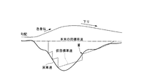
そして、そのCCエコモードのスロットル上限開度を保っても、目標車速に対する実車速の車速偏差が、そのCCエコモードにおける車速偏差閾値越える場合には、そのCCエコモードから1つ上のグレードのCCエコモードに移行する。 Next, an outline of throttle opening control at the time of cruise control by the vehicle travel control apparatus of the present invention will be described based on the uphill road model of FIG.
In this vehicle travel control device, when load fluctuation occurs during cruise control, a plurality of modes (hereinafter referred to as CCs) are used for the same target vehicle speed in order to prevent deterioration of fuel consumption due to excessive control of the throttle opening. Eco mode) is set. A throttle upper limit opening and a vehicle speed deviation threshold are set for each of these CC eco modes.
In these CC eco-modes, when the vehicle speed deviation of the actual vehicle speed with respect to the target vehicle speed is within the vehicle speed deviation threshold in the CC eco-mode, the target throttle opening within a range not exceeding the throttle upper limit opening in the CC eco-mode. After setting, throttle opening is controlled.
If the vehicle speed deviation of the actual vehicle speed with respect to the target vehicle speed exceeds the threshold value of the vehicle speed deviation in the CC eco-mode even if the throttle upper limit opening degree of the CC eco-mode is maintained, the grade higher than the CC eco-mode Transition to CC eco-mode.
図2に示される例では、CCエコモード1における車速偏差閾値ΔVcc12は2km/hであり、CCエコモード2における車速偏差閾値ΔVcc23は3km/hであり、CCエコモード3における車速偏差閾値ΔVcc34は4km/hであり、CCエコモード4における車速偏差閾値ΔVcc45は5km/hである。なお、最上位のCCエコモード5におけるスロットル上限開度は、スロットル全開である。 In this embodiment, five grades of CC eco-mode from the lowest CC eco-mode 1 to the highest CC eco-mode 5 are set. For the CC eco modes 1 to 4, a throttle upper limit opening THh and a vehicle speed deviation threshold value ΔVcc are set in accordance with the running state. Here, the throttle upper limit opening THh is set to a larger value as the higher grade CC eco-mode is entered. Further, the vehicle speed deviation threshold value ΔVcc is also set to a larger value as the higher grade CC eco-mode is entered.
In the example shown in FIG. 2, the vehicle speed deviation threshold value ΔVcc12 in the CC eco mode 1 is 2 km / h, the vehicle speed deviation threshold value ΔVcc23 in the CC eco mode 2 is 3 km / h, and the vehicle speed deviation threshold value ΔVcc34 in the CC eco mode 3 is The vehicle speed deviation threshold value ΔVcc45 in the CC eco mode 4 is 5 km / h. Note that the throttle upper limit opening in the uppermost CC eco-mode 5 is the throttle fully open.
図2に示すように、車両がほぼ平坦路をクルーズコントロール走行しているときには、CCエコモードの中でスロットル上限開度THhおよび車速偏差閾値ΔVccのいずれもが一番小さい値に設定されたCCエコモード1が適用される。
CCエコモード1においては、目標車速に対する実車速の車速偏差ΔVが、CCエコモード1における車速偏差閾値ΔVcc12(図2の例では2km/h)以内の場合は、CCエコモード1におけるスロットル上限開度THh1を越えない範囲で目標スロットル開度を設定した後、スロットル開度を制御する。 Hereinafter, with reference to FIG. 2, an embodiment in the case of cruise control traveling on an uphill road where the gradient gradually increases will be described in time series.
As shown in FIG. 2, when the vehicle is cruising on a substantially flat road, the CC upper limit opening THh and the vehicle speed deviation threshold value ΔVcc are both set to the smallest value in the CC eco mode. Eco mode 1 is applied.
In the CC eco-mode 1, when the vehicle speed deviation ΔV of the actual vehicle speed with respect to the target vehicle speed is within the vehicle speed deviation threshold value ΔVcc12 (2 km / h in the example of FIG. 2) in the CC eco-mode 1, the throttle upper limit opening in the CC eco-mode 1 is opened. After setting the target throttle opening within a range not exceeding the degree THh1, the throttle opening is controlled.
このような場合には、CCエコモード1から1つ上のグレードのCCエコモード2に変更する一方、スロットル上限開度THhおよび車速偏差閾値ΔVccをCCエコモード1のときよりも大きい値(THh2、ΔVcc23)にそれぞれ変更する。 First, while the road gradient is small, cruise control traveling in CC eco mode 1 is possible. Next, when the vehicle proceeds on the uphill road, the running resistance increases as the road gradient gradually increases, so the actual vehicle speed decreases. Here, if the target throttle opening is kept at the throttle upper limit opening THh1 in the CC eco-mode 1, it becomes impossible to suppress the vehicle speed deviation ΔV within the vehicle speed deviation threshold ΔVcc12.
In such a case, the CC eco-mode 1 is changed from the CC eco-mode 1 to the CC eco-mode 2 which is one level higher, while the throttle upper limit opening THh and the vehicle speed deviation threshold value ΔVcc are larger than those in the CC eco-mode 1 (THh2 , ΔVcc23).
このような場合には、CCエコモード2から1つ上のグレードのCCエコモード3に変更する一方、スロットル上限開度THhおよび車速偏差閾値ΔVccをCCエコモード2よりも大きい値(THh3、ΔVcc34)にそれぞれ変更する。 In the CC eco mode 2, when the road gradient is further increased, the running resistance is further increased, so that the actual vehicle speed is decreased. Here, if the target throttle opening is held at the throttle upper limit opening THh2 in the CC eco mode 2, it becomes impossible to suppress the vehicle speed deviation ΔV within the vehicle speed deviation threshold ΔVcc23.
In such a case, the CC eco mode 3 is changed from the CC eco mode 2 to the CC eco mode 3 which is one level higher, while the throttle upper limit opening THh and the vehicle speed deviation threshold value ΔVcc are larger than the CC eco mode 2 (THh3, ΔVcc34). ) Respectively.
このような場合には、CCエコモード3から1つ上のグレードのCCエコモード4に変更する一方、スロットル上限開度THhおよび車速偏差閾値ΔVccをCCエコモード3よりも大きい値(THh4、ΔVcc45)にそれぞれ変更する。 In the CC eco mode 3, when the road gradient further increases, the running resistance further increases, so the actual vehicle speed decreases. Here, if the target throttle opening is kept at the throttle upper limit opening THh3 in the CC eco mode 3, it becomes impossible to suppress the vehicle speed deviation ΔV within the vehicle speed deviation threshold ΔVcc34.
In such a case, the CC eco mode 3 is changed from the CC eco mode 3 to the CC eco mode 4 which is one level higher, while the throttle upper limit opening THh and the vehicle speed deviation threshold value ΔVcc are larger than the CC eco mode 3 (THh4, ΔVcc45 ) Respectively.
このような場合には、CCエコモード4から最上位のグレードであるCCエコモード5に変更する一方、スロットル上限開度THhを全開に設定する。このとき、車速偏差閾値ΔVccは設定しない。 In the CC eco mode 4, when the road gradient is further increased, the running resistance is further increased, so that the actual vehicle speed is decreased. Here, if the target throttle opening is held at the throttle upper limit opening THh4 in the CC eco-mode 4, it becomes impossible to suppress the vehicle speed deviation ΔV within the vehicle speed deviation threshold ΔVcc45.
In such a case, the CC eco mode 4 is changed to the CC eco mode 5 which is the highest grade, while the throttle upper limit opening THh is set to fully open. At this time, the vehicle speed deviation threshold value ΔVcc is not set.
CCエコモード5においては、スロットル開度全開までの範囲で、目標スロットル開度を設定した後、スロットル開度を制御する。 When switching from the CC eco mode 4 to the CC eco mode 5, the temporary target vehicle speed is set as in the case of switching from the CC eco mode 1 to the CC eco mode 2. Then, the target throttle opening is calculated using this instead of the original target vehicle speed, while the target vehicle speed returning process is performed to gradually bring the temporary target vehicle speed closer to the original target vehicle speed.
In the CC eco mode 5, after setting the target throttle opening within the range until the throttle opening is fully opened, the throttle opening is controlled.
また、車速偏差ΔVが各CCエコモードにおける車速偏差閾値ΔVccを越えないと、CCエコモードが変更されないため、スロットル上限開度THhが増大しない。これにより、走行中の路面の凹凸等でCCエコモードが変更されるのを抑制できるため(すなわち、スロットル上限開度が切り替わるのを抑制できるため)、燃費向上に寄与する。 Thus, by providing a plurality of throttle upper limit openings THh, it is possible to finely switch the throttle upper limit opening THh in an area with good fuel consumption according to the required driving force of the vehicle, so that the area that exhibits the fuel efficiency effect is uncomfortable. Can be expanded without any problem. In other words, since the throttle upper limit opening can be switched according to the road gradient, the effect of improving the fuel efficiency is great.
Further, if the vehicle speed deviation ΔV does not exceed the vehicle speed deviation threshold value ΔVcc in each CC eco mode, the CC eco mode is not changed, so the throttle upper limit opening THh does not increase. Thereby, since it can suppress that CC eco mode is changed by the unevenness | corrugation of the road surface etc. which are drive | working (that is, it can suppress that a throttle upper limit opening degree switches), it contributes to a fuel consumption improvement.
図3に示すフローチャートは、クルーズコントロールのメインルーチンを示す。この処理は、FI-ECU30によって繰り返し実行される。
まず、ステップS01においてクルーズコントロール実行中か否かを判定する。ここで、クルーズコントロールを実行していないときに、セット/減速スイッチ16がON操作された時は、ステップS01において肯定判定される。一方、クルーズコントロール実行中に解除スイッチ17がON操作された時は、ステップS01において否定判定される。
ステップS01における判定結果が「NO」である場合には、リターンする。 Next, details of the throttle opening control during cruise control in this embodiment will be described based on the flowcharts of FIGS.
The flowchart shown in FIG. 3 shows the main routine of cruise control. This process is repeatedly executed by the FI-
First, it is determined in step S01 whether or not cruise control is being executed. Here, if the set / deceleration switch 16 is turned on when the cruise control is not being executed, an affirmative determination is made in step S01. On the other hand, when the
If the determination result in step S01 is “NO”, the process returns.
次に、ステップS100に進んだ後、スロットル上限開度を決定する。そして、ステップS03で算出した暫定目標スロットル開度を制限する処理を実行する。さらに、次回の制御周期で行われるスロットル上限開度の決定のために、ステップS200に進んだ後、モード決定処理を実行する。そして、ステップS300に進んだ後、目標車速戻し処理を実行する。その後、リターンする。
以下、ステップS100におけるスロットル上限開度決定処理と、ステップS200におけるモード決定処理と、ステップS300における目標車速戻し処理について、順次説明する。 Next, after proceeding to step S03, an increase / decrease amount of the throttle opening is calculated according to the vehicle speed deviation ΔV between the target vehicle speed determined in step S02 and the actual vehicle speed detected by the vehicle speed sensor. Then, the target throttle opening is calculated based on the increase / decrease amount. Here, the target throttle opening calculated in step S03 is a target throttle opening before being restricted (hereinafter referred to as a temporary target throttle opening).
Next, after proceeding to step S100, the throttle upper limit opening is determined. And the process which restrict | limits the temporary target throttle opening calculated by step S03 is performed. Further, in order to determine the throttle upper limit opening degree performed in the next control cycle, after proceeding to step S200, a mode determination process is executed. And after progressing to step S300, a target vehicle speed return process is performed. Then return.
Hereinafter, the throttle upper limit opening determination process in step S100, the mode determination process in step S200, and the target vehicle speed return process in step S300 will be sequentially described.
まず、ステップS100において実行されるスロットル上限開度決定処理を、図4のフローチャートに従って説明する。
まず、ステップS101において、低燃費モードが選択されているか否かを判定する。
ステップS101における判定結果が「NO」である場合には、ステップS102に進む。そして、通常モード時におけるCCエコモード1,2,3,4それぞれのスロットル上限開度THh1,THh2,THh3,THh4を、下記情報(a),(b)に基づき図示しない通常モード用スロットル上限開度マップを参照して設定する。なお、スロットル上限開度THhの大小関係は、THh1<THh2<THh3<THh4とする。
(a)現在の実車速V
(b)現在走行している道路の勾配(道路勾配)I
なお、スロットル上限開度THhと上記情報(a),(b)との相関関係は、以下の通りである。
現在の実車速Vが大きいほど、スロットル上限開度THhは、大きい値に設定される一方、道路勾配Iが大きいほど、スロットル上限開度THhは、大きい値に設定される。
なお、スロットル上限開度は、必要に応じて、目標車速と実車速との偏差や,加速度や,実燃費等に基づいて補正してもよい。 <Throttle upper limit opening determination process>
First, the throttle upper limit opening determination process executed in step S100 will be described with reference to the flowchart of FIG.
First, in step S101, it is determined whether or not the low fuel consumption mode is selected.
If the determination result in step S101 is “NO”, the process proceeds to step S102. Then, the throttle upper limit openings THh1, THh2, THh3, and THh4 of the CC eco modes 1, 2, 3, and 4 in the normal mode are set based on the following information (a) and (b). Set by referring to the degree map. The throttle upper limit opening degree THh is assumed to be THh1 <THh2 <THh3 <THh4.
(A) Current actual vehicle speed V
(B) Road gradient (road gradient) I
The correlation between the throttle upper limit opening THh and the information (a), (b) is as follows.
As the current actual vehicle speed V increases, the throttle upper limit opening THh is set to a larger value, while as the road gradient I increases, the throttle upper limit opening THh is set to a larger value.
Note that the throttle upper limit opening may be corrected based on the deviation between the target vehicle speed and the actual vehicle speed, the acceleration, the actual fuel consumption, or the like, if necessary.
このように、運転者は、低燃費モード切替スイッチ11の操作により、通常モードにおけるスロットル上限開度の制限を受ける駆動力制御と、低燃費モードにおけるスロットル上限開度の制限を受ける駆動力制御のいずれかを選択できる。 On the other hand, if the determination result in step S101 is “YES”, the process proceeds to step S103. The throttle upper limits THh1, THh2, THh3, and THh4 of the CC eco modes 1, 2, 3, and 4 in the low fuel consumption mode are determined based on the current travel information (a) and (b). Set by referring to the mode throttle upper limit opening map. In the low fuel consumption mode, the correlation between the throttle upper limit opening THh and the information (a) and (b) is the same as in the normal mode. The magnitude relationship of the throttle upper limit opening THh is also set to THh1 <THh2 <THh3 <THh4, as in the normal mode.
As described above, the driver can perform driving force control that is restricted by the throttle upper limit opening degree in the normal mode and driving force control that is restricted by the throttle upper limit opening degree in the low fuel consumption mode by operating the fuel efficiency
ステップS104における判定結果が「YES」(CCエコモード≦1)である場合には、ステップS105に進む。そして、CCエコモード1のスロットル上限開度THh1とステップS03で算出した暫定目標スロットル開度の小さい方の開度を、目標スロットル開度に設定する。
一方、ステップS104における判定結果が「NO」(CCエコモード>1)である場合には、ステップS106に進んだ後、現在のCCエコモードが2であるか否かを判定する。
ステップS106における判定結果が「YES」(CCエコモード=2)である場合には、ステップS107に進む。そして、CCエコモード2のスロットル上限開度THh2とステップS03で算出した暫定目標スロットル開度の小さい方の開度を、目標スロットル開度に設定する。 After proceeding from step S102 or S103 to step S104, it is determined whether or not the current CC eco-mode is 1 or less.
If the determination result in step S104 is “YES” (CC eco mode ≦ 1), the process proceeds to step S105. Then, the smaller one of the throttle upper limit opening THh1 in CC eco-mode 1 and the provisional target throttle opening calculated in step S03 is set as the target throttle opening.
On the other hand, if the determination result in step S104 is “NO” (CC eco mode> 1), after proceeding to step S106, it is determined whether or not the current CC eco mode is 2.
If the determination result in step S106 is “YES” (CC eco mode = 2), the process proceeds to step S107. Then, the smaller one of the throttle upper limit opening THh2 in CC eco-mode 2 and the provisional target throttle opening calculated in step S03 is set as the target throttle opening.
ステップS108における判定結果が「YES」(CCエコモード=3)である場合には、ステップS109に進む。そして、CCエコモード3のスロットル上限開度THh3とステップS03で算出した暫定目標スロットル開度の小さい方の開度を、目標スロットル開度に設定する。 On the other hand, if the determination result in step S106 is “NO” (CC eco mode ≠ 2), after proceeding to step S108, it is determined whether or not the current CC eco mode is 3.
If the determination result in step S108 is “YES” (CC eco mode = 3), the process proceeds to step S109. Then, the smaller one of the throttle upper limit opening THh3 in CC eco-mode 3 and the temporary target throttle opening calculated in step S03 is set as the target throttle opening.
ステップS110における判定結果が「YES」(CCエコモード=4)である場合には、ステップS111に進む。そして、CCエコモード4のスロットル上限開度THh4とステップS03で算出した暫定目標スロットル開度の小さい方の開度を、目標スロットル開度に設定した後、本ルーチンの実行を一旦終了する。 On the other hand, if the determination result in step S108 is “NO” (CC eco mode ≠ 3), after proceeding to step S110, it is determined whether the current CC eco mode is 4.
When the determination result in step S110 is “YES” (CC eco mode = 4), the process proceeds to step S111. Then, after setting the smaller one of the throttle upper limit opening THh4 of CC eco-mode 4 and the temporary target throttle opening calculated in step S03 to the target throttle opening, the execution of this routine is temporarily ended.
次に、ステップS200において実行されるモード決定処理を、図5~図9のフローチャートに従って説明する。
図5に示すように、まず、ステップS201において、低燃費モードが選択されているか否かを判定する。
ステップS201における判定結果が「NO」である場合には、ステップS202に進む。そして、通常モード時における移行判定閾値(f)~(h)を、現在設定されている目標車速に基づいて、図示しない通常モード用のそれぞれの閾値マップを参照して設定する。
(f)車速偏差閾値ΔVcc(ΔVcc12,ΔVcc23,ΔVcc34,ΔVcc45,ΔVcc54,ΔVcc43,ΔVcc32,ΔVcc21)
(g)加速度閾値Acc(Acc12,Acc23,Acc34,Acc45,Acc54,Acc43,Acc32,Acc21)
(h)勾配閾値Icc(Icc12,Icc23,Icc34,Icc45,Icc54,Icc43,Icc32,Icc21) <Mode decision processing>
Next, the mode determination process executed in step S200 will be described with reference to the flowcharts of FIGS.
As shown in FIG. 5, first, in step S201, it is determined whether the low fuel consumption mode is selected.
If the determination result in step S201 is “NO”, the process proceeds to step S202. Then, the transition determination threshold values (f) to (h) in the normal mode are set with reference to each threshold map for the normal mode (not shown) based on the currently set target vehicle speed.
(F) Vehicle speed deviation threshold value ΔVcc (ΔVcc12, ΔVcc23, ΔVcc34, ΔVcc45, ΔVcc54, ΔVcc43, ΔVcc32, ΔVcc21)
(G) Acceleration threshold Acc (Acc12, Acc23, Acc34, Acc45, Acc54, Acc43, Acc32, Acc21)
(H) Gradient threshold value Icc (Icc12, Icc23, Icc34, Icc45, Icc54, Icc43, Icc32, Icc21)
一方、勾配が大きいときに車速偏差閾値ΔVccを小さい値に設定した場合には、クルーズコントロールは、実車速Vをその小さい車速偏差閾値ΔVcc以内に収めようとする。このため、目標スロットル開度が大きくなる。よって、この場合には、駆動出力が大きくなるために、燃費が悪化してしまう。 In this embodiment, the vehicle speed deviation threshold value ΔVcc is set based on the target vehicle speed and the gradient of the currently traveling road, while the vehicle speed deviation threshold value ΔVcc is set to a larger value as the road gradient I increases. This is because when the driver runs while accelerating / decelerating, the amount of decrease in vehicle speed increases as the gradient increases. For this reason, the vehicle speed deviation threshold value ΔVcc is set to a larger value as the road gradient I increases. Thereby, it is possible to realize control that does not cause the driver to feel uncomfortable.
On the other hand, when the vehicle speed deviation threshold value ΔVcc is set to a small value when the gradient is large, the cruise control tries to keep the actual vehicle speed V within the small vehicle speed deviation threshold value ΔVcc. For this reason, the target throttle opening is increased. Therefore, in this case, since the drive output becomes large, the fuel consumption is deteriorated.
<車速偏差閾値>
ΔVcc21≦ΔVcc32≦ΔVcc43≦ΔVcc54
ΔVcc12≦ΔVcc23≦ΔVcc34≦ΔVcc45
<加速度閾値>
Acc21≧Acc32≧Acc43≧Acc54
Acc12≧Acc23≧Acc34≧Acc45
<勾配閾値>
Icc21≦Icc32≦Icc43≦Icc54
Icc12≦Icc23≦Icc34≦Icc45
なお、CCエコモードの移行判定閾値は、必要に応じて実燃費等に基づいた補正してもよい。 In addition, each magnitude relationship in each transition determination threshold is set as follows.
<Vehicle speed deviation threshold>
ΔVcc21 ≦ ΔVcc32 ≦ ΔVcc43 ≦ ΔVcc54
ΔVcc12 ≦ ΔVcc23 ≦ ΔVcc34 ≦ ΔVcc45
<Acceleration threshold>
Acc21 ≧ Acc32 ≧ Acc43 ≧ Acc54
Acc12 ≧ Acc23 ≧ Acc34 ≧ Acc45
<Slope threshold>
Icc21 ≦ Icc32 ≦ Icc43 ≦ Icc54
Icc12 ≦ Icc23 ≦ Icc34 ≦ Icc45
The CC eco-mode transition determination threshold value may be corrected based on actual fuel consumption or the like as necessary.
ステップS204における判定結果が「NO」(CCエコモード>1)である場合には、モードがCCエコモード2~5であるので、ステップS205に進んだ後、移行タイマーT12を初期値にセットする。そして、ステップS211(図6参照)に進む。ここで、移行タイマーT12は、CCエコモード1からCCエコモード2への移行を許可すべきか否かを判定するのに必要な時間(以下、移行判定時間という)を計測するタイマーである。このタイマーは、初期値から経過時間を減算していくカウントダウンタイマーである。 After proceeding from step S202 or S203 to step S204, it is determined whether or not the current CC eco mode is 1 or less.
If the determination result in step S204 is “NO” (CC eco-mode> 1), the mode is CC eco-mode 2-5, and after proceeding to step S205, the transition timer T12 is set to the initial value. . Then, the process proceeds to step S211 (see FIG. 6). Here, the transition timer T12 is a timer that measures a time (hereinafter referred to as a transition determination time) necessary to determine whether or not the transition from the CC eco mode 1 to the CC eco mode 2 should be permitted. This timer is a countdown timer that subtracts the elapsed time from the initial value.
ステップS206における判定結果が「NO」(ΔV≦ΔVcc12)である場合には、CCエコモード1を維持すべきであるので、ステップS205に進む。そして、移行タイマーT12を初期値にセットする。 On the other hand, if the determination result in step S204 is “YES” (CC eco mode ≦ 1), the mode is CC eco mode 1, and the process proceeds to step S206. The vehicle speed deviation ΔV between the target vehicle speed and the current actual vehicle speed V is a threshold for determining whether or not the transition from the CC eco mode 1 to the CC eco mode 2 set in steps S202 and S203 should be permitted (ie, the vehicle speed deviation). It is determined whether or not it is larger than the threshold value ΔVcc12).
If the determination result in step S206 is “NO” (ΔV ≦ ΔVcc12), CC eco-mode 1 should be maintained, and the process proceeds to step S205. Then, the transition timer T12 is set to an initial value.
一方、ステップS207における判定結果が「YES」(I>Icc12、且つ、A<Acc12)である場合には、ステップS209に進んだ後、移行タイマーT12が0であるか否かを判定する。 If the determination result in step S207 is “NO” (I> Icc12 or A <Acc12 is not established), the CC eco-mode 1 should be maintained, so the process proceeds to step S208. Then, the transition timer T12 is set to an initial value.
On the other hand, if the determination result in step S207 is “YES” (I> Icc12 and A <Acc12), after proceeding to step S209, it is determined whether or not the transition timer T12 is zero.
ステップS211における判定結果が「NO」(CCエコモード≠2)である場合には、モードがCCエコモード1,3,4,5のいずれかであるので、ステップS212に進む。そして、移行タイマーT23を初期値にセットした後、さらにステップS213に進む。そして、移行タイマーT21を初期値にセットした後、さらにステップS224(図7参照)に進む。ここで、移行タイマーT23は、CCエコモード2からCCエコモード3への移行判定時間を計測するタイマーである。また、移行タイマーT21は、CCエコモード2からCCエコモード1への移行判定時間を計測するタイマーである。これらのタイマーは、いずれも初期値から経過時間を減算していくカウントダウンタイマーである。 Next, as shown in FIG. 6, in step S211, it is determined whether or not the current mode is the CC eco mode 2.
If the determination result in step S211 is “NO” (CC eco mode ≠ 2), the mode is one of the CC eco modes 1, 3, 4, and 5, so the process proceeds to step S212. Then, after the transition timer T23 is set to the initial value, the process further proceeds to step S213. Then, after the transition timer T21 is set to the initial value, the process further proceeds to step S224 (see FIG. 7). Here, the transition timer T23 is a timer for measuring the transition determination time from the CC eco mode 2 to the CC eco mode 3. The transition timer T21 is a timer that measures the transition determination time from the CC eco mode 2 to the CC eco mode 1. Each of these timers is a countdown timer that subtracts the elapsed time from the initial value.
ステップS214における判定結果が「NO」(ΔV≦ΔVcc23)である場合には、CCエコモード3に移行すべきではないので、ステップS215に進む。そして、移行タイマーT23を初期値にセットした後、ステップS218に進む。 On the other hand, if the determination result in step S211 is “YES” (CC eco mode = 2), the mode is CC eco mode 2 and the process proceeds to step S214. Then, whether or not the current vehicle speed deviation ΔV is larger than a determination threshold value (that is, vehicle speed deviation threshold value ΔVcc23) as to whether or not the transition from the CC eco mode 2 to the CC eco mode 3 set in steps S202 and S203 should be permitted. Determine whether.
If the determination result in step S214 is “NO” (ΔV ≦ ΔVcc23), it should not shift to the CC eco-mode 3, and the process proceeds to step S215. Then, after the transition timer T23 is set to an initial value, the process proceeds to step S218.
一方、ステップS216における判定結果が「YES」(I>Icc23、且つ、A<Acc23)である場合には、ステップS219に進んだ後、移行タイマーT23が0であるか否かを判定する。 If the determination result in step S216 is “NO” (I> Icc23 or A <Acc23 is not established), the process proceeds to step S217 because it should not shift to the CC eco-mode 3. Then, after the transition timer T23 is set to an initial value, the process proceeds to step S218.
On the other hand, if the determination result in step S216 is “YES” (I> Icc23 and A <Acc23), after proceeding to step S219, it is determined whether or not the transition timer T23 is zero.
一方、ステップS218における判定結果が「YES」(ΔV<ΔVcc21、I<Icc21、TH<THh1、A>Acc21が全て成立)である場合には、ステップS222に進んだ後、移行タイマーT21が0であるか否かを判定する。 If the determination result in step S218 is “NO” (at least one of ΔV <ΔVcc21, I <Icc21, TH <THh1, A> Acc21 is not established), it should not shift to CC eco-mode 1. The process proceeds to step S221. Then, after the transition timer T21 is set to the initial value, the process proceeds to step S224.
On the other hand, if the determination result in step S218 is “YES” (ΔV <ΔVcc21, I <Icc21, TH <THh1, A> Acc21 are all established), after proceeding to step S222, the transition timer T21 is 0. It is determined whether or not there is.
ステップS224における判定結果が「NO」(CCエコモード≠3)である場合には、モードがCCエコモード1,2,4,5のいずれかであるので、ステップS225に進む。そして、移行タイマーT34を初期値にセットした後、さらにステップS226に進む。そして、移行タイマーT32を初期値にセットした後、さらにステップS237(図8参照)に進む。ここで、移行タイマーT34は、CCエコモード3からCCエコモード4への移行判定時間を計測するタイマーである。また、移行タイマーT32は、CCエコモード3からCCエコモード2への移行判定時間を計測するタイマーである。これらのタイマーは、いずれも初期値から経過時間を減算していくカウントダウンタイマーである。 Next, as shown in FIG. 7, it is determined in step S224 whether or not the current mode is the CC eco mode 3.
If the determination result in step S224 is “NO” (CC eco mode ≠ 3), the mode is one of CC eco modes 1, 2, 4, and 5, and the process proceeds to step S225. Then, after setting the transition timer T34 to the initial value, the process further proceeds to step S226. Then, after the transition timer T32 is set to the initial value, the process further proceeds to step S237 (see FIG. 8). Here, the transition timer T34 is a timer that measures the transition determination time from the CC eco mode 3 to the CC eco mode 4. The transition timer T32 is a timer for measuring the transition determination time from the CC eco mode 3 to the CC eco mode 2. Each of these timers is a countdown timer that subtracts the elapsed time from the initial value.
ステップS227における判定結果が「NO」(ΔV≦ΔVcc34)である場合には、CCエコモード4に移行すべきではないので、ステップS228に進む。そして、移行タイマーT34を初期値にセットした後、ステップS231に進む。 On the other hand, if the determination result in step S224 is “YES” (CC eco mode = 3), the mode is CC eco mode 3, and the process proceeds to step S227. Then, whether or not the current vehicle speed deviation ΔV is larger than a determination threshold value (that is, vehicle speed deviation threshold value ΔVcc34) as to whether or not the transition from the CC eco mode 3 to the CC eco mode 4 set in steps S202 and S203 should be permitted. Determine whether.
If the determination result in step S227 is “NO” (ΔV ≦ ΔVcc34), the process proceeds to step S228 because the CC eco mode 4 should not be entered. Then, after setting the transition timer T34 to the initial value, the process proceeds to step S231.
一方、ステップS229における判定結果が「YES」(I>Icc34、且つ、A<Acc34)である場合には、ステップS232に進んだ後、移行タイマーT34が0であるか否かを判定する。 If the determination result in step S229 is “NO” (I> Icc34 or A <Acc34 is not established), the process proceeds to step S230 because the CC eco-mode 4 should not be entered. Then, after setting the transition timer T34 to the initial value, the process proceeds to step S231.
On the other hand, if the determination result in step S229 is “YES” (I> Icc34 and A <Acc34), after proceeding to step S232, it is determined whether or not the transition timer T34 is zero.
一方、ステップS231における判定結果が「YES」(ΔV<ΔVcc32、I<Icc32、TH<THh2、A>Acc32が全て成立)である場合には、ステップS235に進んだ後、移行タイマーT32が0であるか否かを判定する。 If the determination result in step S231 is “NO” (at least one of ΔV <ΔVcc32, I <Icc32, TH <THh2, A> Acc32 is not established), it should not shift to the CC eco-mode 2. The process proceeds to step S234. Then, after the transition timer T32 is set to the initial value, the process proceeds to step S237.
On the other hand, if the determination result in step S231 is “YES” (ΔV <ΔVcc32, I <Icc32, TH <THh2, A> Acc32 are all established), after proceeding to step S235, the transition timer T32 is 0. It is determined whether or not there is.
ステップS237における判定結果が「NO」(CCエコモード≠4)である場合には、モードがCCエコモード1,2,3,5のいずれかであるので、ステップS238に進む。そして、移行タイマーT45を初期値にセットした後、さらにステップS239に進む。そして、移行タイマーT43を初期値にセットした後、さらにステップS250(図8参照)に進む。ここで、移行タイマーT45は、CCエコモード4からCCエコモード5への移行判定時間を計測するタイマーである。また、移行タイマーT43は、CCエコモード4からCCエコモード3への移行判定時間を計測するタイマーである。これらのタイマーは、いずれも初期値から経過時間を減算していくカウントダウンタイマーである。 Next, as shown in FIG. 8, it is determined in step S237 whether the current mode is the CC eco mode 4.
If the determination result in step S237 is “NO” (CC eco mode ≠ 4), the mode is one of the CC eco modes 1, 2, 3, and 5, so the process proceeds to step S238. Then, after the transition timer T45 is set to the initial value, the process further proceeds to step S239. Then, after the transition timer T43 is set to the initial value, the process further proceeds to step S250 (see FIG. 8). Here, the transition timer T45 is a timer that measures the transition determination time from the CC eco mode 4 to the CC eco mode 5. The transition timer T43 is a timer for measuring the transition determination time from the CC eco mode 4 to the CC eco mode 3. Each of these timers is a countdown timer that subtracts the elapsed time from the initial value.
ステップS240における判定結果が「NO」(ΔV≦ΔVcc45)である場合には、CCエコモード5に移行すべきではないので、ステップS241に進む。そして、移行タイマーT45を初期値にセットした後、ステップS244に進む。 On the other hand, if the determination result in step S237 is “YES” (CC eco mode = 4), the mode is CC eco mode 4, and the process proceeds to step S240. Then, whether or not the current vehicle speed deviation ΔV is larger than a determination threshold value (ie, vehicle speed deviation threshold value ΔVcc45) for determining whether or not to allow the transition from the CC eco mode 4 to the CC eco mode 5 set in steps S202 and S203. Determine whether.
If the determination result in step S240 is “NO” (ΔV ≦ ΔVcc45), it should not shift to the CC eco-mode 5, and the process proceeds to step S241. Then, after the transition timer T45 is set to the initial value, the process proceeds to step S244.
一方、ステップS242における判定結果が「YES」(I>Icc45、且つ、A<Acc45)である場合には、ステップS245に進んだ後、移行タイマーT45が0であるか否かを判定する。 If the determination result in step S242 is “NO” (I> Icc45 or A <Acc45 is not established), the process proceeds to step S243 because the mode should not be shifted to the CC eco-mode 5. Then, after the transition timer T45 is set to the initial value, the process proceeds to step S244.
On the other hand, if the determination result in step S242 is “YES” (I> Icc45 and A <Acc45), after proceeding to step S245, it is determined whether or not the transition timer T45 is zero.
一方、ステップS244における判定結果が「YES」(ΔV<ΔVcc43、I<Icc43、TH<THh3、A>Acc43が全て成立)である場合には、ステップS248に進んだ後、移行タイマーT43が0であるか否かを判定する。 If the determination result in step S244 is “NO” (at least one of ΔV <ΔVcc43, I <Icc43, TH <THh3, A> Acc43 is not established), it should not shift to CC eco-mode 3. The process proceeds to step S247. Then, after the transition timer T43 is set to the initial value, the process proceeds to step S250.
On the other hand, if the determination result in step S244 is “YES” (ΔV <ΔVcc43, I <Icc43, TH <THh3, A> Acc43 are all established), after proceeding to step S248, the transition timer T43 is 0. It is determined whether or not there is.
ステップS250における判定結果が「NO」(CCエコモード≠5)である場合には、モードがCCエコモード1,2,3,4のいずれかであるので、ステップS251に進む。そして、移行タイマーT54を初期値にセットし、本ルーチンの実行を一旦終了する。ここで、移行タイマーT54は、CCエコモード5からCCエコモード4への移行判定時間を計測するタイマーである。このタイマーは、初期値から経過時間を減算していくカウントダウンタイマーである。 Next, as shown in FIG. 9, it is determined whether or not the current mode is the CC eco mode 5 in step S250.
If the determination result in step S250 is “NO” (CC eco mode ≠ 5), the mode is one of the CC eco modes 1, 2, 3, and 4, so the process proceeds to step S251. Then, the transition timer T54 is set to an initial value, and the execution of this routine is once ended. Here, the transition timer T54 is a timer that measures the transition determination time from the CC eco mode 5 to the CC eco mode 4. This timer is a countdown timer that subtracts the elapsed time from the initial value.
一方、ステップS252における判定結果が「YES」(ΔV<ΔVcc54、I<Icc54、TH<THh4、A>Acc54が全て成立)である場合には、ステップS254に進んだ後、移行タイマーT54が0であるか否かを判定する。 If the determination result in step S252 is “NO” (at least one of ΔV <ΔVcc54, I <Icc54, TH <THh4, A> Acc54 is not established), it should not shift to the CC eco-mode 4. The process proceeds to step S253. Then, after the transition timer T54 is set to an initial value, the execution of this routine is temporarily terminated.
On the other hand, if the determination result in step S252 is “YES” (ΔV <ΔVcc54, I <Icc54, TH <THh4, A> Acc54 are all established), after proceeding to step S254, the transition timer T54 is 0. It is determined whether or not there is.
さらに、スロットル上限開度THhの大きさに対応して車速偏差閾値ΔVccを設定している。ここでは、スロットル上限開度THhが大きいほど車速偏差閾値ΔVccを大きい値に設定している。このため、大きなスロットル上限開度THhに設定されるほど、そのスロットル上限開度THhによる出力制限の領域を拡大できる。よって、燃費効果のある領域を違和感なく拡大できる。 In the mode determination process in this embodiment, since a plurality of throttle upper limit openings THh are set at the same target vehicle speed, the throttle upper limit opening THh can be finely switched in a fuel-efficient region according to the required driving force of the vehicle. it can. Therefore, the area where the fuel efficiency effect is exhibited can be expanded without a sense of incompatibility. In other words, since the throttle upper limit opening can be switched according to the road gradient, the effect of improving the fuel efficiency is great.
Further, a vehicle speed deviation threshold value ΔVcc is set corresponding to the magnitude of the throttle upper limit opening THh. Here, the larger the throttle upper limit opening THh, the larger the vehicle speed deviation threshold value ΔVcc is set. For this reason, the larger the throttle upper limit opening THh is set, the larger the range of output restriction by the throttle upper limit opening THh can be expanded. Therefore, it is possible to expand a region having a fuel efficiency effect without a feeling of strangeness.
次に、ステップS300において実行される目標車速戻し処理を、図10のフローチャートに従って説明する。
まず、ステップS301において、低燃費モードが選択されているか否かを判定する。
ステップS301における判定結果が「NO」である場合には、ステップS302に進む。そして、通常モード時においてCCエコモードのグレードを切り替える際に適用する、仮目標車速から本来の目標車速への移行割合を、下記情報(j)~(o)に基づき、図示しない通常モード用移行割合マップを参照して、あるいは計算式により演算した後、これを設定する。
この移行割合は、換言すると、仮目標車速の単位時間当たりの変化量の制限値(以下、変化量制限値という)である。
(j)現在の実車速V
(k)現在の実車速Vと本来の目標車速との車速偏差ΔV
(l)加速度A
(m)現在走行している道路の勾配I
(n)切り替え前後のCCエコモードのグレード
(o)CCエコモードの切り替え開始からの経過時間t <Target vehicle speed return processing>
Next, the target vehicle speed return process executed in step S300 will be described with reference to the flowchart of FIG.
First, in step S301, it is determined whether the low fuel consumption mode is selected.
If the determination result in step S301 is “NO”, the process proceeds to step S302. Based on the following information (j) to (o), the transition ratio for the normal mode (not shown) is applied to the transition ratio from the temporary target vehicle speed to the original target vehicle speed that is applied when switching the CC eco-mode grade in the normal mode. This is set with reference to the ratio map or after calculation using a calculation formula.
In other words, the transition ratio is a limit value of the change amount per unit time of the temporary target vehicle speed (hereinafter referred to as a change amount limit value).
(J) Current actual vehicle speed V
(K) Vehicle speed deviation ΔV between the current actual vehicle speed V and the original target vehicle speed
(L) Acceleration A
(M) Road slope I currently traveling
(N) CC eco-mode grade before and after switching (o) Elapsed time t from the start of CC eco-mode switching
これは、上り勾配のときに移行割合(変化量制限値)を小さく設定することにより、本来の目標車速への移行をゆっくりできるからである。そのため、登坂路におけるエンジンの駆動力出力を低く抑えられるので、燃費向上の効果がある。
一方、降坂路では元々エンジンの駆動力出力が少ない。そこで、下り勾配のときに移行割合(変化量制限値)を大きく設定することにより、本来の目標車速への戻しを積極的に行うことができる。これにより、移行時の燃費を向上できる。また、運転者は、降坂路であるのに実車速が本来の目標車速に戻ってくるのが遅いと、違和感を感じてしまう。そこで、下り勾配のときに移行割合(変化量制限値)を大きく設定することにより、運転者がこのような違和感を感じないようにできる。 Further, when the road gradient I is an ascending slope, the transition rate (change amount limit value) is set small, while when the road gradient I is a descending slope, the transition rate (change amount limit value) is set large. To do.
This is because the transition to the original target vehicle speed can be slowed by setting the transition rate (change amount limit value) small when the vehicle is going uphill. As a result, the driving force output of the engine on the uphill road can be kept low, which has the effect of improving fuel consumption.
On the other hand, the driving force output of the engine is originally low on the downhill road. Therefore, by setting a large transition rate (change amount limit value) when the vehicle is descending, it is possible to positively return to the original target vehicle speed. Thereby, the fuel consumption at the time of transfer can be improved. In addition, the driver feels uncomfortable when the actual vehicle speed is slow to return to the original target vehicle speed even though it is a downhill road. Therefore, by setting a large transition ratio (change amount limit value) when the vehicle is on a downward slope, it is possible to prevent the driver from feeling such discomfort.
また、実際の加速が目標車速移行割合に比べて小さい場合、戻し中の目標車速との車速差が大きくなる。そのため、その後の加速度が大きくなることを防止するために、移行割合を小さくする。
また、切り替え前後のCCエコモードのグレードは、上記車速偏差ΔV及び道路勾配Iと相関関係があるため、ΔV,Iの代替値として切り替え前後のCCエコモードグレードを使用することもできる。 In addition, the elapsed time t from the start of CC eco-mode switching is measured by a target vehicle speed return timer, which will be described later, and then the transition rate (change amount limit value) is corrected based on the elapsed time t and the vehicle speed deviation ΔV. May be. For example, when the vehicle speed deviation ΔV does not decrease despite the increase in the elapsed time t, the shift ratio (change amount limit value) is corrected to be increased more than usual. As a result, the convergence of the actual vehicle speed to the target vehicle speed can be accelerated.
Further, when the actual acceleration is smaller than the target vehicle speed transition rate, the vehicle speed difference from the returning target vehicle speed becomes large. Therefore, in order to prevent the subsequent acceleration from increasing, the transition rate is reduced.
Also, since the CC eco-mode grade before and after the switching has a correlation with the vehicle speed deviation ΔV and the road gradient I, the CC eco-mode grade before and after the switching can be used as an alternative value for ΔV and I.
一方、ステップS304における判定結果が「NO」(モード切り替えなし)である場合には、ステップS305,S306の処理を実行することなく、ステップS307に進む。 Next, the process proceeds from step S305 to step S306. Then, after timing by the target vehicle speed return timer is started, the process proceeds to step S307. The target vehicle speed return timer is a timer that measures an elapsed time since the mode is switched. This timer is a count-up timer that starts from 0 and counts up.
On the other hand, if the determination result in step S304 is “NO” (no mode switching), the process proceeds to step S307 without executing the processes in steps S305 and S306.
なお、現在の実車速Vの値を仮目標車速とする代わりに、仮目標車速を移行割合(変化量制限値)以上に増加させてもよい。 Here, when the actual vehicle speed V becomes larger than the temporary target vehicle speed by a predetermined value or more as shown at a point M in FIG. 11 while the temporary target vehicle speed is gradually approaching the original target vehicle speed, The actual vehicle speed V is set as the temporary target vehicle speed. Thus, by increasing the temporary target vehicle speed more than usual, it is possible to accelerate the convergence of the vehicle speed to the original target vehicle speed.
Instead of using the current actual vehicle speed V as the temporary target vehicle speed, the temporary target vehicle speed may be increased to a shift rate (change amount limit value) or more.
ステップS309における判定結果が「NO」(実車速<本来の目標車速)である場合には、本ルーチンの実行を一旦終了する。
また、ステップS307における判定結果が「NO」である場合、および、ステップS309における判定結果が「YES」である場合には、ステップS310に進む。
ステップS307における判定結果が「NO」である場合は、仮目標車速を適用して目標スロットル開度の算出を行っていないか、あるいは、運転者に加速する意志がある場合である。この場合には、ステップS310において、仮目標車速を直ちに本来の目標車速に戻す。これは、アクセルペダルの介入による実車速を増加させる操作等が発生した際に直ちに本来の目標車速に戻すことによって、運転者が違和感を生じることなくスロットル開度制御を本来の状態に戻すためである。 Next, after proceeding from step S308 to step S309, it is determined whether or not the current actual vehicle speed V is equal to or higher than the original target vehicle speed.
If the determination result in step S309 is “NO” (actual vehicle speed <original target vehicle speed), the execution of this routine is temporarily terminated.
If the determination result in step S307 is “NO” and if the determination result in step S309 is “YES”, the process proceeds to step S310.
When the determination result in step S307 is “NO”, the target throttle opening is not calculated by applying the temporary target vehicle speed, or the driver is willing to accelerate. In this case, in step S310, the temporary target vehicle speed is immediately returned to the original target vehicle speed. This is because when the operation to increase the actual vehicle speed by the intervention of the accelerator pedal occurs, the throttle opening control is returned to the original state without causing the driver to feel uncomfortable by immediately returning to the original target vehicle speed. is there.
次に、ステップS310からステップS311に進む。そして、移行タイマーをリセットした後(t=0)、本ルーチンの実行を一旦終了する。 Moreover, when the determination result in step S309 is “YES”, it is when the actual vehicle speed V is equal to or higher than the original target vehicle speed. Therefore, also in this case, the temporary target vehicle speed is immediately returned to the original target vehicle speed in step S310. For example, the actual vehicle speed V may be greater than or equal to the original target vehicle speed when the vehicle speed increases during downhill travel or when the target vehicle speed is changed to the deceleration side by the driver's operation. In such a case, the throttle opening degree control can be returned to the original state without causing the driver to feel uncomfortable by immediately returning to the original target vehicle speed.
Next, the process proceeds from step S310 to step S311. Then, after the transition timer is reset (t = 0), the execution of this routine is temporarily terminated.
しかも、仮目標車速を本来の目標車速に徐々に近づけるので、低下した車速を本来の目標車速に戻すことを行うリカバリー制御を急な加速を伴わずに実施できる。これにより、少ない駆動力の出力で本来の制御状態に戻せる。 In this way, when the throttle upper limit opening is switched to a more restrictive throttle upper limit opening, the temporary target vehicle speed is set, while the temporary target vehicle speed is used instead of the original target vehicle speed and the actual vehicle speed V is set. A vehicle speed deviation ΔV is calculated. Since the target throttle opening is calculated on the basis of the vehicle speed deviation, it is possible to prevent a sudden increase in the throttle opening (that is, a sudden increase in driving force output) accompanying the switching of the throttle upper limit opening. Thereby, fuel consumption can be improved.
Moreover, since the temporary target vehicle speed is gradually brought closer to the original target vehicle speed, recovery control for returning the reduced vehicle speed to the original target vehicle speed can be performed without sudden acceleration. Thus, the original control state can be restored with a small driving force output.
この図から、実施形態の場合には比較例の場合よりも車速の変動は大きくなるが、スロットル開度の変動を抑制できることがわかる。したがって、実施形態の方が比較例よりも燃費が良くなる。 FIG. 13 is a time chart of throttle opening and the like during cruise control travel. The lower half of this figure shows a case where a plurality of throttle upper limit openings are set and throttle opening control (driving force control) is performed during cruise control traveling as in the above-described embodiment. The upper half of this figure shows a case where the throttle opening degree control is performed without setting the throttle upper limit opening degree.
From this figure, it can be seen that in the case of the embodiment, the variation in the vehicle speed is larger than that in the comparative example, but the variation in the throttle opening can be suppressed. Therefore, the fuel efficiency of the embodiment is better than that of the comparative example.
なお、本発明の技術範囲は、上述した実施形態のみに限定されるものではなく、本発明の趣旨を逸脱しない範囲において、上述した実施形態に種々の変更を加えたものを含む。すなわち、本実施形態で挙げた具体的な処理や構成等は一例にすぎず、適宜変更が可能である。
例えば、上述した実施形態では、目標駆動力算出手段で算出する目標駆動力を目標スロットル開度としたが、目標駆動力はアクセルペダル開度やトルクとしてもよい。 [Other Embodiments]
It should be noted that the technical scope of the present invention is not limited to the above-described embodiments, but includes those in which various modifications are made to the above-described embodiments without departing from the spirit of the present invention. That is, the specific processing, configuration, and the like given in this embodiment are merely examples, and can be changed as appropriate.
For example, in the above-described embodiment, the target driving force calculated by the target driving force calculating means is the target throttle opening, but the target driving force may be an accelerator pedal opening or torque.
31 エンジン・ミッションコントロール部(勾配量取得手段)
32 クルーズコントロール部
34 スロットル開度制御部(駆動力制御部)
35 目標車速設定部(目標車速設定手段)
36 車速低下許容値設定部(車速低下許容値設定手段)
37 スロットル上限開度算出部(目標駆動力上限値算出手段)
38 目標スロットル開度算出部(目標駆動力算出手段) 14
32
35 Target vehicle speed setting section (target vehicle speed setting means)
36 Vehicle speed reduction allowable value setting section (vehicle speed reduction allowable value setting means)
37 Throttle upper limit opening calculation unit (target driving force upper limit calculation means)
38 Target throttle opening calculation unit (target driving force calculation means)
Claims (12)
- 車両の実車速を検出する車速センサと;
目標車速を設定する目標車速設定部と;
この目標車速設定部により設定された前記目標車速と前記車速センサにより検出された前記実車速との車速偏差に基づいて目標駆動力を算出する目標駆動力算出部と;
この目標駆動力算出部で算出された前記目標駆動力に基づいて駆動力制御を行う駆動力制御部と;
前記目標車速に対する前記実車速の低下許容値を設定する車速低下許容値設定部と;
前記実車速に基づいて目標駆動力上限値を算出する目標駆動力上限値算出部と;
を備え、
前記目標車速に対する前記実車速の低下量が前記低下許容値以内である場合に、
前記目標駆動力算出部が、前記目標駆動力上限値算出部により算出された前記目標駆動力上限値以下に前記目標駆動力を制限するとともに、
前記駆動力制御部が、前記制限された目標駆動力に基づいて駆動力制御を行う
ことを特徴とする車両用走行制御装置。 A vehicle speed sensor for detecting the actual vehicle speed;
A target vehicle speed setting unit for setting the target vehicle speed;
A target driving force calculation unit that calculates a target driving force based on a vehicle speed deviation between the target vehicle speed set by the target vehicle speed setting unit and the actual vehicle speed detected by the vehicle speed sensor;
A driving force control unit that performs driving force control based on the target driving force calculated by the target driving force calculation unit;
A vehicle speed reduction allowable value setting unit that sets a reduction allowable value of the actual vehicle speed with respect to the target vehicle speed;
A target driving force upper limit value calculation unit for calculating a target driving force upper limit value based on the actual vehicle speed;
With
When the decrease amount of the actual vehicle speed with respect to the target vehicle speed is within the allowable decrease value,
The target driving force calculation unit limits the target driving force to be equal to or less than the target driving force upper limit value calculated by the target driving force upper limit value calculation unit;
The vehicle driving control device, wherein the driving force control unit performs driving force control based on the limited target driving force. - 前記目標駆動力上限値算出部が、複数の異なる目標駆動力上限値を算出し;
前記目標駆動力算出部が、前記実車速が前記目標車速よりも前記低下許容値以上低下した場合に、このとき設定されている目標駆動力上限値よりも大きな目標駆動力上限値に切り替えて目標駆動力の制限を行う;
ことを特徴とする請求項1に記載の車両用走行制御装置。 The target driving force upper limit calculating unit calculates a plurality of different target driving force upper limit values;
The target driving force calculating unit switches to a target driving force upper limit value that is larger than the target driving force upper limit value set at this time when the actual vehicle speed is lower than the target vehicle speed by the decrease allowable value or more. Limit the driving force;
The vehicular travel control apparatus according to claim 1. - 前記低下許容値設定部が、前記目標駆動力上限値算出部が算出した前記複数の目標駆動力上限値の大きさに対応して低下許容値を設定し、前記複数の目標駆動力上限値が大きいほど前記低下許容値を大きい値に設定する
ことを特徴とする請求項2に記載の車両用走行制御装置。 The allowable reduction value setting unit sets an allowable decrease value corresponding to the size of the plurality of target driving force upper limit values calculated by the target driving force upper limit value calculating unit, and the plurality of target driving force upper limit values are The vehicle travel control apparatus according to claim 2, wherein the lower allowable value is set to a larger value as the value is larger. - 前記目標駆動力算出部が、
前記目標駆動力上限値の切り替えを行う際に、現在の実車速または目標車速に基づいて求められた仮の目標車速を、目標車速設定部により設定された本来の目標車速の代わりに用いて前記目標駆動力を算出するとともに、前記仮の目標車速を前記本来の目標車速に徐々に近づける
ことを特徴とする請求項2に記載の車両用走行制御装置。 The target driving force calculation unit is
When switching the target driving force upper limit value, the temporary target vehicle speed obtained based on the current actual vehicle speed or the target vehicle speed is used instead of the original target vehicle speed set by the target vehicle speed setting unit. The vehicle travel control apparatus according to claim 2, wherein a target driving force is calculated and the temporary target vehicle speed is gradually brought closer to the original target vehicle speed. - 前記目標駆動力算出部が、
前記仮の目標車速の単位時間当たりの変化量を制限することにより前記仮の目標車速を前記本来の目標車速に徐々に近づけ、
また、前記仮の目標車速の単位時間当たりの変化量制限値を、前記実車速または前記実車速と前記本来の目標車速との偏差に基づいて算出する
ことを特徴とする請求項4に記載の車両用走行制御装置。 The target driving force calculation unit is
By limiting the amount of change per unit time of the temporary target vehicle speed, the temporary target vehicle speed is gradually brought closer to the original target vehicle speed,
5. The change amount limit value per unit time of the temporary target vehicle speed is calculated based on the actual vehicle speed or a deviation between the actual vehicle speed and the original target vehicle speed. Vehicle travel control device. - 前記仮の目標車速を前記本来の目標車速に徐々に近づける間に前記実車速が前記本来の目標車速以上となった場合に、
前記目標駆動力算出部が、前記仮の目標車速を用いた前記目標駆動力の算出を中止して、前記本来の目標車速を用いた前記目標駆動力の算出を開始する
ことを特徴とする請求項4に記載の車両用走行制御装置。 When the actual vehicle speed becomes equal to or higher than the original target vehicle speed while gradually approaching the temporary target vehicle speed to the original target vehicle speed,
The target driving force calculation unit stops calculation of the target driving force using the temporary target vehicle speed and starts calculating the target driving force using the original target vehicle speed. Item 5. The vehicle travel control device according to Item 4. - 前記仮の目標車速を前記本来の目標車速に徐々に近づける間に前記実車速が前記仮の目標車速よりも所定値以上大きくなった場合に、
前記目標駆動力算出部が、現在の実車速の値を前記仮の目標車速として設定するか、もしくは前記仮の目標車速を前記変化量制限値以上に増加させる
ことを特徴とする請求項5に記載の車両用走行制御装置。 When the actual vehicle speed becomes larger than the temporary target vehicle speed by a predetermined value or more while gradually approaching the temporary target vehicle speed to the original target vehicle speed,
6. The target driving force calculation unit sets a current actual vehicle speed value as the temporary target vehicle speed, or increases the temporary target vehicle speed to be greater than or equal to the change amount limit value. The vehicle travel control device described. - 自車走行路の勾配量を取得する勾配量取得部をさらに備え;
前記目標駆動力上限値算出部が、前記勾配量取得部により取得された前記勾配量に基づいて前記目標駆動力上限値を算出する;
ことを特徴とする請求項1に記載の車両用走行制御装置。 A gradient amount acquisition unit for acquiring a gradient amount of the own vehicle travel path;
The target driving force upper limit calculating unit calculates the target driving force upper limit value based on the gradient amount acquired by the gradient amount acquiring unit;
The vehicular travel control apparatus according to claim 1. - 自車走行路の勾配量を取得する勾配量取得部をさらに備え;
前記目標駆動力上限値算出部が、前記勾配量取得部により取得された前記勾配量に基づいて前記目標駆動力上限値を算出し;
前記目標車速に対する前記実車速の低下量が前記低下許容値よりも大きく、且つ、前記勾配量取得部により取得された前記勾配量が予め定められた判定閾値以上となる場合に、前記目標駆動力算出部が、このとき設定されている目標駆動力上限値よりも大きな目標駆動力上限値を用いて前記目標駆動力の制限を行う;
ことを特徴とする請求項2に記載の車両用走行制御装置。 A gradient amount acquisition unit for acquiring a gradient amount of the own vehicle travel path;
The target driving force upper limit calculating unit calculates the target driving force upper limit value based on the gradient amount acquired by the gradient amount acquiring unit;
When the amount of decrease in the actual vehicle speed with respect to the target vehicle speed is larger than the allowable decrease value and the gradient amount acquired by the gradient amount acquisition unit is equal to or greater than a predetermined determination threshold, the target driving force The calculation unit limits the target driving force using a target driving force upper limit value larger than the target driving force upper limit value set at this time;
The vehicular travel control apparatus according to claim 2. - 前記低下許容値設定部が、前記勾配量取得部により取得された前記勾配量の増加に応じて前記目標車速に対する前記実車速の前記低下許容値を増加させる
ことを特徴とする請求項8に記載の車両用走行制御装置。 9. The allowable decrease value setting unit increases the allowable decrease value of the actual vehicle speed with respect to the target vehicle speed in accordance with an increase in the gradient amount acquired by the gradient amount acquisition unit. Vehicle travel control device. - 前記目標駆動力算出部が、前記仮の目標車速の単位時間当たりの変化量を制限することにより仮の目標車速を前記本来の目標車速に徐々に近づけ、前記勾配量取得部により取得された前記勾配量に基づいて、前記仮の目標車速の単位時間当たりの変化量制限値を算出する
ことを特徴とする請求項8に記載の車両用走行制御装置。 The target driving force calculation unit limits the amount of change per unit time of the temporary target vehicle speed to gradually bring the temporary target vehicle speed closer to the original target vehicle speed, and is acquired by the gradient amount acquisition unit. 9. The vehicular travel control apparatus according to claim 8, wherein a change amount limit value per unit time of the temporary target vehicle speed is calculated based on a gradient amount. - 駆動力制御内容を、前記目標駆動力を制限する通常モードと、前記目標駆動力を通常モードよりもさらに制限する低燃費モードとの間で切り換えるモード切換部をさらに備え;
前記通常モードにおける前記目標駆動力上限値と前記低燃費モードにおける前記目標駆動力上限値とを異ならせる;
ことを特徴とする請求項1に記載の車両用走行制御装置。 A mode switching unit for switching the driving force control contents between a normal mode for limiting the target driving force and a low fuel consumption mode for further limiting the target driving force as compared with the normal mode;
Making the target driving force upper limit value in the normal mode different from the target driving force upper limit value in the low fuel consumption mode;
The vehicular travel control apparatus according to claim 1.
Priority Applications (4)
| Application Number | Priority Date | Filing Date | Title |
|---|---|---|---|
| US13/131,915 US8463522B2 (en) | 2008-12-04 | 2009-11-12 | Vehicle running control device |
| CN200980145888.5A CN102216140B (en) | 2008-12-04 | 2009-11-12 | Vehicle running control device |
| CA2744984A CA2744984C (en) | 2008-12-04 | 2009-11-12 | Vehicle running control device |
| EP09830134.4A EP2364892B1 (en) | 2008-12-04 | 2009-11-12 | Vehicle running control device |
Applications Claiming Priority (2)
| Application Number | Priority Date | Filing Date | Title |
|---|---|---|---|
| JP2008-309918 | 2008-12-04 | ||
| JP2008309918A JP4806704B2 (en) | 2008-12-04 | 2008-12-04 | Vehicle travel control device |
Publications (1)
| Publication Number | Publication Date |
|---|---|
| WO2010064363A1 true WO2010064363A1 (en) | 2010-06-10 |
Family
ID=42233022
Family Applications (1)
| Application Number | Title | Priority Date | Filing Date |
|---|---|---|---|
| PCT/JP2009/006039 WO2010064363A1 (en) | 2008-12-04 | 2009-11-12 | Vehicle running control device |
Country Status (6)
| Country | Link |
|---|---|
| US (1) | US8463522B2 (en) |
| EP (1) | EP2364892B1 (en) |
| JP (1) | JP4806704B2 (en) |
| CN (1) | CN102216140B (en) |
| CA (1) | CA2744984C (en) |
| WO (1) | WO2010064363A1 (en) |
Families Citing this family (20)
| Publication number | Priority date | Publication date | Assignee | Title |
|---|---|---|---|---|
| CN102470867B (en) * | 2009-07-02 | 2015-04-08 | 沃尔沃拉斯特瓦格纳公司 | Method and system for controlling a vehicle cruise control |
| RU2014130046A (en) * | 2011-12-22 | 2016-02-10 | Сканиа Св Аб | METHOD AND MODULE FOR MANAGING VEHICLE SPEED ON THE BASIS OF RULES AND / OR VALUES |
| KR101578502B1 (en) * | 2011-12-22 | 2015-12-18 | 스카니아 씨브이 악티에볼라그 | Method and module for determining of at least one reference value |
| DE102012204596A1 (en) * | 2012-03-22 | 2013-09-26 | Ford Global Technologies, Llc | Method and device for regulating the speed of a motor vehicle |
| JP2014009987A (en) * | 2012-06-28 | 2014-01-20 | Micware Co Ltd | On-vehicle device, driving assist method, and program |
| GB2505022B (en) * | 2012-08-16 | 2015-01-14 | Jaguar Land Rover Ltd | Speed control system and method for operating the same |
| KR101467377B1 (en) * | 2013-08-28 | 2014-12-10 | (주)로드피아 | Cruise control method of vehicle and apparatus thereof |
| GB2519533B (en) * | 2013-10-23 | 2018-04-04 | Jaguar Land Rover Ltd | Vehicle speed control system |
| CA2906024C (en) * | 2014-09-24 | 2022-07-26 | Eric Amback | Low speed cruise control for a vehicle |
| US10124784B2 (en) * | 2015-04-13 | 2018-11-13 | Ford Global Technologies, Llc | Method and system for controlling shifting of a vehicle in cruise control |
| CN108349493B (en) * | 2015-11-09 | 2019-06-14 | 日产自动车株式会社 | Braking and drive force control method and braking force control device |
| CN106240364B (en) * | 2016-07-28 | 2019-03-26 | 大连大学 | A kind of automatic transmission vehicle driving Scene Simulation system and control method |
| CN106671776B (en) * | 2016-12-09 | 2019-03-22 | 重庆长安汽车股份有限公司 | Vehicle Speed control system and method based on driver's operation |
| AT519888B1 (en) * | 2017-04-25 | 2019-02-15 | Avl List Gmbh | METHOD FOR OPERATING A VEHICLE |
| US10787174B2 (en) | 2017-10-13 | 2020-09-29 | Toyota Motor Engineering & Manufacutring North America, Inc. | Automatic vehicle driving mode system |
| KR20190072311A (en) * | 2017-12-15 | 2019-06-25 | 현대자동차주식회사 | Apparatus for limiting speed of a vehicle and method thereof |
| JP7070309B2 (en) * | 2018-10-10 | 2022-05-18 | トヨタ自動車株式会社 | Vehicle control unit |
| CN111703423B (en) * | 2019-03-18 | 2022-05-06 | 毫末智行科技有限公司 | Longitudinal control safety monitoring method and system for automatic driving vehicle |
| CN112896138B (en) * | 2019-11-19 | 2022-11-29 | 北京车和家信息技术有限公司 | Vehicle speed limiting method and device and vehicle |
| CN116368044A (en) * | 2020-11-06 | 2023-06-30 | 日产自动车株式会社 | Vehicle control method and vehicle control device |
Citations (5)
| Publication number | Priority date | Publication date | Assignee | Title |
|---|---|---|---|---|
| JP2003343305A (en) | 2002-05-30 | 2003-12-03 | Toyota Motor Corp | Cruise control device |
| JP2005042699A (en) * | 2003-07-04 | 2005-02-17 | Honda Motor Co Ltd | Control device of hybrid vehicle |
| JP2007296976A (en) * | 2006-04-28 | 2007-11-15 | Honda Motor Co Ltd | Travel controller for vehicle |
| JP2008095635A (en) * | 2006-10-13 | 2008-04-24 | Toyota Motor Corp | Driving force control device |
| JP2008309918A (en) | 2007-06-13 | 2008-12-25 | Panasonic Corp | Plasma display device, and driving method of plasma display panel |
Family Cites Families (7)
| Publication number | Priority date | Publication date | Assignee | Title |
|---|---|---|---|---|
| JPH1148823A (en) * | 1997-08-04 | 1999-02-23 | Mitsubishi Motors Corp | Constant-speed driving device for vehicle |
| JP2003291687A (en) * | 2002-04-04 | 2003-10-15 | Mitsubishi Fuso Truck & Bus Corp | Speed control device for vehicle |
| US20040084237A1 (en) * | 2002-05-30 | 2004-05-06 | Petrie Alfred E. | Vehicle cruise control system |
| JP3613264B2 (en) * | 2002-06-18 | 2005-01-26 | 日産自動車株式会社 | Driving assistance device for vehicle |
| DE102005017965A1 (en) | 2005-04-19 | 2006-10-26 | Cristobal Guzman | About the fuel consumption controlled motor vehicle |
| DE102005045891B3 (en) * | 2005-09-26 | 2007-02-15 | Siemens Ag | Fuel consumption reduction method e.g. for internal combustion engine, involves specifying operating window of motor vehicle with wind direction and wind velocity recorded to determine wind conditions on vehicle |
| DE102006045502A1 (en) * | 2006-09-27 | 2008-04-03 | Jungheinrich Ag | Device for controlling a hybrid drive system for a motor vehicle, in particular an industrial truck |
-
2008
- 2008-12-04 JP JP2008309918A patent/JP4806704B2/en active Active
-
2009
- 2009-11-12 US US13/131,915 patent/US8463522B2/en active Active
- 2009-11-12 CN CN200980145888.5A patent/CN102216140B/en active Active
- 2009-11-12 CA CA2744984A patent/CA2744984C/en not_active Expired - Fee Related
- 2009-11-12 EP EP09830134.4A patent/EP2364892B1/en not_active Not-in-force
- 2009-11-12 WO PCT/JP2009/006039 patent/WO2010064363A1/en active Application Filing
Patent Citations (5)
| Publication number | Priority date | Publication date | Assignee | Title |
|---|---|---|---|---|
| JP2003343305A (en) | 2002-05-30 | 2003-12-03 | Toyota Motor Corp | Cruise control device |
| JP2005042699A (en) * | 2003-07-04 | 2005-02-17 | Honda Motor Co Ltd | Control device of hybrid vehicle |
| JP2007296976A (en) * | 2006-04-28 | 2007-11-15 | Honda Motor Co Ltd | Travel controller for vehicle |
| JP2008095635A (en) * | 2006-10-13 | 2008-04-24 | Toyota Motor Corp | Driving force control device |
| JP2008309918A (en) | 2007-06-13 | 2008-12-25 | Panasonic Corp | Plasma display device, and driving method of plasma display panel |
Non-Patent Citations (1)
| Title |
|---|
| See also references of EP2364892A4 * |
Also Published As
| Publication number | Publication date |
|---|---|
| JP4806704B2 (en) | 2011-11-02 |
| US8463522B2 (en) | 2013-06-11 |
| CA2744984A1 (en) | 2010-06-10 |
| US20110246042A1 (en) | 2011-10-06 |
| EP2364892B1 (en) | 2014-12-31 |
| CN102216140A (en) | 2011-10-12 |
| EP2364892A1 (en) | 2011-09-14 |
| EP2364892A4 (en) | 2013-05-15 |
| JP2010132132A (en) | 2010-06-17 |
| CA2744984C (en) | 2013-07-09 |
| CN102216140B (en) | 2014-03-19 |
Similar Documents
| Publication | Publication Date | Title |
|---|---|---|
| WO2010064363A1 (en) | Vehicle running control device | |
| WO2022062572A1 (en) | Multidimensional-based gear shifting control method and device, vehicle and medium | |
| JP4519895B2 (en) | Shift indicator device | |
| JP5162916B2 (en) | Hybrid regenerative braking control device for hybrid vehicle | |
| KR102518733B1 (en) | Cruise control system and method for vehicle | |
| JP2007038933A (en) | Vehicle travel control device | |
| JP2008168700A (en) | Hybrid vehicle | |
| JPH09112671A (en) | Shift control device of continuously variable transmission | |
| WO2013046381A1 (en) | Vehicle control apparatus | |
| JP6020338B2 (en) | Vehicle control device | |
| JP4265240B2 (en) | Vehicle driving force control device | |
| EP2754925B1 (en) | Control device for continuously variable transmission | |
| JP2001235016A (en) | Driving force control device for automobile | |
| CN108374887B (en) | Vehicle control device | |
| JP2009121394A (en) | Device for controlling number of rotations of driving force source | |
| JP2010284979A (en) | Braking and driving force control device | |
| JP2010112397A (en) | Speed-change controller for continuously variable transmission | |
| JP4120532B2 (en) | Shift control device for automatic transmission | |
| JP3465445B2 (en) | Transmission control device for continuously variable transmission | |
| JPH0735227A (en) | Automatic transmission with down slope passage down shift control | |
| JP2006142963A (en) | Driving force control device for vehicle | |
| JP5071335B2 (en) | Driving force control device | |
| JP2007231963A (en) | Shift control device for vehicular automatic transmission | |
| JP2005147215A (en) | Speed change control unit for vehicle | |
| JP2004060734A (en) | Gear change control device of automatic transmission |
Legal Events
| Date | Code | Title | Description |
|---|---|---|---|
| WWE | Wipo information: entry into national phase |
Ref document number: 200980145888.5 Country of ref document: CN |
|
| 121 | Ep: the epo has been informed by wipo that ep was designated in this application |
Ref document number: 09830134 Country of ref document: EP Kind code of ref document: A1 |
|
| WWE | Wipo information: entry into national phase |
Ref document number: 2744984 Country of ref document: CA |
|
| WWE | Wipo information: entry into national phase |
Ref document number: 13131915 Country of ref document: US |
|
| NENP | Non-entry into the national phase |
Ref country code: DE |
|
| WWE | Wipo information: entry into national phase |
Ref document number: 2009830134 Country of ref document: EP |