WO2010058863A1 - Dispositif de traitement de signal, procédé de traitement de signal, programme de traitement de signal, support d'enregistrement lisible par ordinateur sur lequel est enregistré un programme de traitement de signal, et dispositif de radiothérapie - Google Patents
Dispositif de traitement de signal, procédé de traitement de signal, programme de traitement de signal, support d'enregistrement lisible par ordinateur sur lequel est enregistré un programme de traitement de signal, et dispositif de radiothérapie Download PDFInfo
- Publication number
- WO2010058863A1 WO2010058863A1 PCT/JP2009/069992 JP2009069992W WO2010058863A1 WO 2010058863 A1 WO2010058863 A1 WO 2010058863A1 JP 2009069992 W JP2009069992 W JP 2009069992W WO 2010058863 A1 WO2010058863 A1 WO 2010058863A1
- Authority
- WO
- WIPO (PCT)
- Prior art keywords
- time
- series signal
- information
- input
- prediction
- Prior art date
Links
Images


Classifications
-
- A—HUMAN NECESSITIES
- A61—MEDICAL OR VETERINARY SCIENCE; HYGIENE
- A61N—ELECTROTHERAPY; MAGNETOTHERAPY; RADIATION THERAPY; ULTRASOUND THERAPY
- A61N5/00—Radiation therapy
- A61N5/10—X-ray therapy; Gamma-ray therapy; Particle-irradiation therapy
- A61N5/1048—Monitoring, verifying, controlling systems and methods
- A61N5/1064—Monitoring, verifying, controlling systems and methods for adjusting radiation treatment in response to monitoring
- A61N5/1065—Beam adjustment
- A61N5/1067—Beam adjustment in real time, i.e. during treatment
-
- A—HUMAN NECESSITIES
- A61—MEDICAL OR VETERINARY SCIENCE; HYGIENE
- A61N—ELECTROTHERAPY; MAGNETOTHERAPY; RADIATION THERAPY; ULTRASOUND THERAPY
- A61N5/00—Radiation therapy
- A61N5/10—X-ray therapy; Gamma-ray therapy; Particle-irradiation therapy
- A61N5/103—Treatment planning systems
- A61N5/1037—Treatment planning systems taking into account the movement of the target, e.g. 4D-image based planning
-
- A—HUMAN NECESSITIES
- A61—MEDICAL OR VETERINARY SCIENCE; HYGIENE
- A61N—ELECTROTHERAPY; MAGNETOTHERAPY; RADIATION THERAPY; ULTRASOUND THERAPY
- A61N5/00—Radiation therapy
- A61N5/10—X-ray therapy; Gamma-ray therapy; Particle-irradiation therapy
- A61N5/1048—Monitoring, verifying, controlling systems and methods
- A61N5/1064—Monitoring, verifying, controlling systems and methods for adjusting radiation treatment in response to monitoring
- A61N5/1069—Target adjustment, e.g. moving the patient support
- A61N5/107—Target adjustment, e.g. moving the patient support in real time, i.e. during treatment
-
- G—PHYSICS
- G06—COMPUTING; CALCULATING OR COUNTING
- G06F—ELECTRIC DIGITAL DATA PROCESSING
- G06F17/00—Digital computing or data processing equipment or methods, specially adapted for specific functions
- G06F17/10—Complex mathematical operations
- G06F17/15—Correlation function computation including computation of convolution operations
- G06F17/153—Multidimensional correlation or convolution
-
- G—PHYSICS
- G16—INFORMATION AND COMMUNICATION TECHNOLOGY [ICT] SPECIALLY ADAPTED FOR SPECIFIC APPLICATION FIELDS
- G16H—HEALTHCARE INFORMATICS, i.e. INFORMATION AND COMMUNICATION TECHNOLOGY [ICT] SPECIALLY ADAPTED FOR THE HANDLING OR PROCESSING OF MEDICAL OR HEALTHCARE DATA
- G16H20/00—ICT specially adapted for therapies or health-improving plans, e.g. for handling prescriptions, for steering therapy or for monitoring patient compliance
- G16H20/40—ICT specially adapted for therapies or health-improving plans, e.g. for handling prescriptions, for steering therapy or for monitoring patient compliance relating to mechanical, radiation or invasive therapies, e.g. surgery, laser therapy, dialysis or acupuncture
-
- G—PHYSICS
- G21—NUCLEAR PHYSICS; NUCLEAR ENGINEERING
- G21K—TECHNIQUES FOR HANDLING PARTICLES OR IONISING RADIATION NOT OTHERWISE PROVIDED FOR; IRRADIATION DEVICES; GAMMA RAY OR X-RAY MICROSCOPES
- G21K1/00—Arrangements for handling particles or ionising radiation, e.g. focusing or moderating
- G21K1/02—Arrangements for handling particles or ionising radiation, e.g. focusing or moderating using diaphragms, collimators
- G21K1/04—Arrangements for handling particles or ionising radiation, e.g. focusing or moderating using diaphragms, collimators using variable diaphragms, shutters, choppers
- G21K1/046—Arrangements for handling particles or ionising radiation, e.g. focusing or moderating using diaphragms, collimators using variable diaphragms, shutters, choppers varying the contour of the field, e.g. multileaf collimators
-
- A—HUMAN NECESSITIES
- A61—MEDICAL OR VETERINARY SCIENCE; HYGIENE
- A61N—ELECTROTHERAPY; MAGNETOTHERAPY; RADIATION THERAPY; ULTRASOUND THERAPY
- A61N5/00—Radiation therapy
- A61N5/10—X-ray therapy; Gamma-ray therapy; Particle-irradiation therapy
- A61N5/1048—Monitoring, verifying, controlling systems and methods
- A61N2005/1074—Details of the control system, e.g. user interfaces
Definitions
- the present invention relates to a signal processing device, a signal processing method, a signal processing program, a computer-readable recording medium on which the signal processing program is recorded, and a radiation therapy device including the signal processing device.
- the radiotherapy apparatus includes, for example, a radiotherapy apparatus that accurately irradiates radiation to a position of an affected part of a patient.
- Radiotherapy apparatuses that perform treatment by irradiating an affected area (for example, a tumor) of a patient with radiation (for example, an ion beam such as a proton beam or a heavy particle beam or an X-ray) are known.
- an ion beam such as a proton beam or a heavy particle beam or an X-ray
- the position and shape of the affected area may vary depending on, for example, the patient's breathing.
- a method of acquiring a fluoroscopic image in which a subtle contrast is ensured by controlling the irradiation timing for fluoroscopic image acquisition and the activation timing of therapeutic radiation, or time-series data Predicting the most probable affected part position at the time of therapeutic radiation irradiation based on the above, a method for accurately and safely irradiating the affected part with radiation, and the obtained fluoroscopic image of the irradiation target as a reference image for a specific evaluation factor
- a method of performing irradiation control with high reliability for an irradiation target by comparing with the above is known.
- prediction is performed by simply applying an autoregressive model to an input time-series signal obtained by using an observation signal of an affected part position as an input.
- Such prediction is used, for example, when predicting the affected part position after a very short time (for example, about 0.15 seconds).
- the shape and size of the passage window of the collimator that forms the radiation irradiation range is controlled so that the radiation irradiation position follows the affected part position.
- the present invention has been devised in view of the above-described problems, and an object thereof is to predict an input time-series signal of an affected part position accurately and in the medium to long term.
- the present invention is not limited to the above-described object, and can be positioned as one of other objects that is an effect obtained by each configuration shown in the embodiments to be described later and that cannot be obtained by conventional techniques. .
- the following means are used. (1) By assuming that a certain component of the input time-series signal is a time-series signal whose period changes with time, a correlation analysis between a part of the input time-series signal and the input time-series signal is performed, and the correlation analysis is performed. Is used to estimate the period variation of the input time series signal and the reliability of the period variation, and the period until the predetermined time after the input time series signal is used using the period variation and the reliability of the period variation.
- in-phase time information that is the time of the input time-series signal that is in phase with the phase after the predetermined time of the input time-series signal
- the periodic fluctuation analysis unit that calculates the reliability of the in-phase time information, the input time series signal, the time series information of the amount of change per unit time of the input time series signal, and the periodic fluctuation analysis unit
- model design information for predicting a value after the predetermined time of the input time-series signal using the reliability of the in-phase time information, and the predetermined time of the input time-series signal based on the model design information
- a prediction accuracy estimator that estimates the accuracy of prediction of a later value, the input time-series signal, the reliability of the in-phase time information and the in-phase time information calculated by the period variation analyzer, and the prediction
- a prediction model for predicting a value after the predetermined time of the input time series signal is created using the model design information estimated by the accuracy estimation unit, and the predetermined
- the prediction accuracy estimation unit estimates the model design information using information regarding a calculation process of the value after the predetermined time of the input time series signal output by the model creation unit. You may do it.
- the periodic fluctuation analysis unit uses a correlation analysis unit that performs a correlation analysis between a part of the input time series signal and the input time series signal, and uses an analysis result in the correlation analysis unit, A period estimator for estimating a period variation and a reliability of the period variation; and using the period variation and the reliability of the period variation estimated by the period estimator until the predetermined time after the input time-series signal.
- the model creation unit may create the prediction model using a plurality of submodels having different structures and characteristics.
- the sub-model is at least a Sarima (Seasonal Auto-Regressive Moving Moving Average) model, a seasonally adjusted exponential smoothing model, a nonlinear ARIMA (Auto-Regressive Integrated Moving Average) model, and a neural network, Any of the computing models may be used.
- the model creation unit may change the sub-model using the accuracy of prediction of the value after the predetermined time of the input time series signal estimated by the prediction accuracy estimation unit. .
- a certain component of the input time-series signal is a time-series signal whose period changes with time
- a correlation analysis between a part of the input time-series signal and the input time-series signal is performed, Using the result of the correlation analysis, the period fluctuation of the input time series signal and the reliability of the period fluctuation are estimated, and the period fluctuation and the reliability of the period fluctuation are used until a predetermined time after the input time series signal.
- Information and the reliability of the in-phase time information, the input time-series signal, the time-series information of the amount of change per unit time of the input time-series signal, the calculated in-phase time information and the Reliability of in-phase time information Is used to estimate model design information for predicting the value after the predetermined time of the input time-series signal, and accuracy of prediction of the value after the predetermined time of the input time-series signal based on the model design information
- a signal processing method can be used in which a prediction model that predicts a later value is created, and the value after the predetermined time of the input time-series signal is predicted and output using the prediction model.
- a radiotherapy apparatus for irradiating an affected part of a patient with radiation, wherein the radiation generating part for generating the radiation and a collimator for forming an irradiation range of the radiation generated from the radiation generating part in a desired shape
- the position of the affected area after the predetermined time using the input time series signal related to the position of the affected area measured by the measurement section Calculating the radiation irradiation position and irradiation range using the signal processing apparatus for estimating information, the position after a predetermined time of the affected part predicted by the signal processing apparatus and the accuracy information, and
- a radiation therapy apparatus including a drive control unit that drives and controls the collimator unit based on the calculation result can be used.
- the radiation therapy apparatus controls the generation timing of the radiation in the radiation generation unit using the position after the predetermined time of the affected part predicted by the signal processing apparatus and the accuracy information.
- a timing control unit may be provided.
- a radiotherapy apparatus for irradiating an affected part of a patient with radiation, the radiation generating part for generating the radiation, a measuring part for measuring a position of the affected part, and the affected part measured by the measuring part.
- the signal processing device for estimating the position of the affected area after a predetermined time and the accuracy information of the predicted position using the input time-series signal related to the position of the affected area, and the predetermined of the affected area predicted by the signal processing apparatus
- a radiotherapy apparatus including a control unit that controls the irradiation timing of the radiation in the radiation generation unit using the position after the time and the accuracy information can be used.
- the signal processing program for causing a computer to realize the prediction function, the signal processing program being an input time series signal Is assumed to be a time-series signal whose period changes with time, thereby performing a correlation analysis between a part of the input time-series signal and the input time-series signal, and using the result of the correlation analysis, Estimating the period variation of the input time series signal and the reliability of the period variation, predicting the period of the input time series signal up to a predetermined time using the period variation and the reliability of the period variation, and analyzing the correlation In-phase time information that is the time of the input time-series signal that is in phase with the phase after the predetermined time of the input time-series signal and the same-phase time
- a periodic fluctuation analysis function for calculating the reliability of the information, the input time series signal, the time series information of the amount of change per unit time of the input time series signal, and the same phase calculated by the periodic
- a computer-readable recording medium recording a signal processing program for causing a computer to realize the prediction function
- the signal processing program performs a correlation analysis between a part of the input time-series signal and the input time-series signal by assuming that a certain component of the input time-series signal is a time-series signal whose period changes with time.
- the period fluctuation of the input time series signal and the reliability of the period fluctuation are estimated, and the period fluctuation and the reliability of the period fluctuation are used until a predetermined time after the input time series signal.
- Period variation analysis function for calculating in-phase time information that is the time of the current and the reliability of the in-phase time information, the input time-series signal, and the time-series information of the amount of change per unit time of the input time-series signal
- Model design information for predicting the value of the input time-series signal after the predetermined time using the in-phase time information calculated by the periodic variation analysis function and the reliability of the in-phase time information
- a prediction accuracy estimation function that estimates the accuracy of prediction of the value after the predetermined time of the input time series signal based on the model design information, the input time series signal, and the same phase calculated by the period variation analysis function
- Prediction for predicting a value after the predetermined time of the input time-series signal using time information and reliability of the in-phase time information and the model design information estimated by the prediction accuracy estimation function
- a computer-readable recording of a signal processing program that creates a
- the future information of the input time series signal can be predicted accurately and in the medium to long term.
- the affected area can be irradiated accurately and continuously.
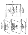
- FIG. (A) is a figure which shows the external appearance of MLC210
- FIG. (B) is a figure which shows an example of a structure of MLC210
- 2 is a diagram illustrating an example of a configuration of an OBI 220.
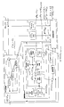
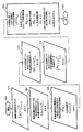
- FIG. 2 is a diagram illustrating an example of a configuration of a control unit 1.
- FIG. (A) to (C) are diagrams showing an example of the operation of the period variation analyzer 12.
- (A) to (D) are diagrams illustrating an operation example of the correlation analysis unit 121.
- (A) to (C) are diagrams illustrating an operation example of the period estimation unit 123.
- FIG. (A)-(D) is a figure which shows the operation example of the same phase time estimation part 125.
- FIG. (A) And (B) is a figure which shows the operation example of the model preparation part 11.
- FIG. (A) And (B) is a figure which shows the operation example of the prediction precision estimation part 16.
- FIG. It is a figure which shows the three-dimensional plot of the predetermined observation position of the affected part 260.
- FIG. It is a figure which shows each axis
- FIG. 14 is a figure which shows the actual measurement value and prediction value of each axis
- (B) And (C) is a figure which shows the prediction accuracy estimation information by the prediction accuracy estimation part 16.
- FIG. It is a figure which shows the measured value of each signal component about each axis
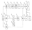
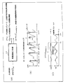
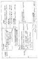
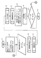
- FIG. 1 shows an overview of a radiotherapy device.
- the radiotherapy apparatus shown in FIG. 1 exemplarily includes a control unit 1, a klystron 100, a cooling device 110, a waveguide 120, a vacuum pump 130, an electron gun 140, an acceleration tube 150, and a deflection.
- An electromagnet 160, a target 170, and a flattening filter (scattering foil) 180 are provided.
- 1 exemplarily includes a monitor dosimeter 190, an irradiation field forming unit [Jaw, (JAW)] 200, an MLC (Multi Leaf Collimator) 210, and an OBI (On-Board Imager). ) 220, a bed 230, an EPID (Electronic Portal Imaging Device) 240, and a pulse modulator 250.
- Jaw, (JAW) irradiation field forming unit
- MLC Multi Leaf Collimator
- OBI On-Board Imager
- the control unit 1 predicts the position information of the affected part 260 after a predetermined time from the position information (position, shape, size, etc.) of the affected part 260 measured by the OBI 220. And the control part 1 implement
- the radiotherapy apparatus illustrated in FIG. 1 has the functional blocks illustrated in FIG.
- the pulse modulator 250 is a voltage generation source that generates a pulse voltage.
- the pulse modulator 250 of the present example generates a predetermined pulse voltage triggered by the input of a trigger pulse from a trigger pulse generator (not shown), for example.
- the klystron 100 is an electron tube that amplifies a high frequency using an interaction between an electron beam and a high frequency to output a high-power microwave.
- the klystron 100 according to the present embodiment generates, for example, an electron beam by a pulse voltage received from the pulse modulator 250, modulates the speed of the electron beam, and outputs the electron beam from the gap, thereby accelerating electrons in the acceleration tube 150.
- the microwave pulse power is output.
- the cooling device 110 has a function of cooling the klystron 100.
- a cooling method for example, there is a method in which a cavity is provided between the body part covering the main body part of the klystron 100 and the main body part, and cooling water is introduced into the cavity for cooling.
- the waveguide 120 transmits the microwave pulse power output from the klystron 100 to the acceleration tube 150.
- a hollow waveguide can be used as the waveguide 120, but a coaxial cable using a dielectric such as Teflon (registered trademark) can also be used.
- the vacuum pump 130 is a pump for discharging a gas from the container to form a vacuum state.
- a vacuum state is formed in the vicinity of the electron beam emitting portion of the electron gun 140, the internal space of the acceleration tube 150, and the vicinity of the deflection electromagnet 160. By maintaining each of these portions in a vacuum state, loss of microwave pulse power output from the klystron 100 and energy loss of an electron beam emitted from the electron gun 140 can be reduced.
- a dry pump with a small degree of erosion into the inside of the acceleration tube 150 can be used.
- a wet pump using oil can also be used.
- the electron gun 140 takes out free electrons from a predetermined metal material and emits an electron beam. For example, electrons in a solid are emitted into a space by high heat or a high electric field, and the emitted electrons are accelerated by applying an electric field, and an electron beam is focused and irradiated by an electron lens.
- the electron gun 140 for example, a field emission electron gun that takes out electrons into the space by the quantum mechanical tunnel effect can be used.
- a thermoelectron emission electron gun that emits electrons by thermal energy or the like can be used. You can also.
- the acceleration tube 150 amplifies the energy of the electron beam emitted from the electron gun 140 using the microwave pulse power output from the klystron 100 and transmitted by the waveguide 120.
- the electron beam is accelerated by the microwave pulse power and emitted from the acceleration tube 150.
- the deflection electromagnet 160 corrects the trajectory of the electron beam emitted from the acceleration tube 150 by generating a magnetic field in a predetermined direction.
- the deflection electromagnet 160 of the present example uses three deflection electromagnets 160 to correct the trajectory of the electron beam in order to irradiate the target 170 with the electron beam.
- the number of deflection electromagnets 160 is not limited to the example shown in FIG.
- the target 170 is a material that emits radiation when irradiated with an electron beam.
- the target 170 for example, tungsten (Tg) can be used. Note that other materials may be used as long as they can generate radiation by irradiation with an accelerated electron beam. That is, the pulse modulator 250, the klystron 100, the cooling device 110, the waveguide 120, the vacuum pump 130, the electron gun 140, the acceleration tube 150, the deflection electromagnet 160, and the target 170 function as an example of a radiation generating unit that generates radiation. .
- the flattening filter 180 is a filter that attenuates and flattens the dose distribution of the radiation irradiated from the target 170.
- the flattening filter 180 of this example attenuates the dose level of the radiation irradiated from the target 170 according to the wavelength, for example, and sets the dose level of the radiation to a predetermined level (for example, a dose level that allows radiation to the human body).
- a predetermined level for example, a dose level that allows radiation to the human body.
- the monitor dosimeter 190 measures the radiation dose level. With the monitor dosimeter 190 of this example, for example, it is possible to measure and confirm whether or not the radiation dose level after passing through the flattening filter 180 is attenuated to a predetermined level. If the radiation dose level is not attenuated to a predetermined level, the dose level can be adjusted by controlling the microwave pulse power in the klystron 100, for example.
- the JAW200 is an irradiation field forming member made of a material that blocks radiation.
- the JAW 200 is composed of, for example, a plurality of plate-like members. By determining each position of the plate-like member, the JAW 200 allows a part of the radiation irradiated from the target 170 to pass through and blocks the others, thereby A rough field is formed.
- the radiation irradiation field can be narrowed down so that the radiation falls within a range where input to the MLC 210 located at the subsequent stage of the JAW 200 is possible.
- the MLC (collimator unit) 210 forms an irradiation range of radiation irradiated from the target 170 in a desired shape.
- the MLC 210 of this example can change the radiation irradiation range after passing through the JAW 200 according to, for example, the position of the affected part 260 predicted by the control unit 1 and the prediction accuracy information after a predetermined time.
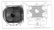
- 3A and 3B show an overview and a configuration example of the MLC 210. FIG.
- the MLC 210 includes, for example, a plurality of pairs of plate-like members (leafs) that block radiation. Each leaf is independently displaced in the left-right direction on the paper surface to cooperate to form a radiation irradiation field [a central space portion in FIG. 3A] 304 in a desired shape.
- the radiation that has passed through the JAW 200 passes through the MLC 210 in the direction perpendicular to the plane of the drawing, so that the affected part 260 can be irradiated with radiation within a range corresponding to the shape of the radiation field 304.
- the MLC 210 includes a plurality of leaves 303, drive units 302-1 and 302-2, and a drive control unit 301, as illustrated in FIG. 3B.
- the leaf 303 is a plate-like member that can block radiation. In this example, for example, two opposing leaves 303 form a pair to form a plurality of leaf pairs. Each leaf 303 is independently driven by driving units 302-1 and 302-2. The number of leaves 303 is not limited to the illustrated example.
- the driving units 302-1 and 302-2 displace each leaf 303 independently.
- the drive units 302-1 and 302-2 drive each leaf 303 with a motor or the like provided individually on each leaf 303, and displace it along the leaf movement direction in the drawing.
- the leaf 303 on the right side of the paper surface is driven by the driving unit 302-1 and the leaf 303 on the left side of the paper surface is driven by the driving unit 302-2.
- the leaves 303 can be displaced in conjunction by the driving units 302-1 and 302-2.
- the surrounding leaf 303 may be displaced in conjunction.
- the drive control unit 301 controls the drive units 302-1 and 302-2 to determine the position of each leaf 303.
- Each leaf 303 is independently positioned and controlled at a desired position, whereby a radiation field 304 having a desired shape is formed.
- the drive control unit 301 of this example controls the drive units 302-1 and 302-2 based on the prediction result (predicted position and prediction accuracy information of the affected part 260 after a predetermined time) by the control unit 1, for example.
- the position of the leaf 303 is determined.
- the radiation irradiation field 304 having a desired shape can be formed in accordance with the position, shape, and size of the affected part 260 after a predetermined time predicted by the control unit 1. , Radiation irradiation suitable for the shape and size can be realized.
- the OBI (measurement unit) 220 measures the position of the affected part 260. For example, it is possible to irradiate the measurement target with X-rays and output position information regarding the position, shape, size, etc. of the measurement target.
- the OBI 220 of this example for example, based on a plurality of pieces of position information obtained by irradiating the patient's affected part 260 with X-rays from a plurality of angles, observes (actually measured values) such as the position, shape, and size of the affected part 260. Is calculated.
- Position information regarding the position, shape, size, and the like of the affected part 260 actually measured by the OBI 220 is input to the control unit 1 and used for prediction processing described later.
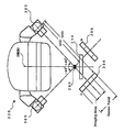
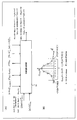
- FIG. 4 shows a configuration example of the OBI 220.
- the OBI 220 exemplarily includes an X-ray irradiation unit 305 and a sensor panel (Sensor Panel) 306.
- the X-ray irradiation unit 305 irradiates the affected part 260 of the patient on the bed 230 with X-rays.
- X-rays are a kind of radiation, and are, for example, electromagnetic waves having a wavelength of about 1 pm to 10 nm.
- the sensor panel 306 has a sensor for detecting X-rays on the surface, and outputs the position coordinates of the irradiated X-rays.
- the sensor panel 306 of this example receives, for example, the X-ray after passing through the affected area 260 in an imaging area, and calculates and outputs the two-dimensional coordinates of the reception position.
- the X-ray irradiation unit 305 and the sensor panel 306 are configured so as to be able to rotate integrally around the rotation axis in FIG. 4, and the sensor panel 306 of this example is, for example, a symbol A in FIG.
- the two-dimensional coordinates P1 (x1, y1) of the affected part 260 calculated at the position indicated by (the position where the X-ray irradiation axis and the rotation axis form an angle of + 45 °), and the position indicated by the symbol B in FIG. Based on the two-dimensional coordinates P2 (x2, y2) of the affected part 260 calculated at a position where the irradiation axis and the rotation axis form an angle of ⁇ 45 °, the three-dimensional coordinates P (X, Y, Z) of the affected part 260 are obtained. calculate.
- the distance from the irradiation point of the X-ray irradiation unit 305 to the affected part 260 is SAD (source-axis distance)
- the distance from the X-ray irradiation point of the X-ray irradiation unit 305 to the surface of the sensor panel 306 is SDD (source ⁇ (detector distance)
- the position coordinate P (X, Y, Z) of the affected part 260 is expressed by the following equation (1).
- the three-dimensional coordinates P (X, Y, Z) of the affected part 260 calculated by the above equation (1) are input to the control unit 1 as an actual measurement value (input signal) indicating the current position of the affected part 260, for example, and control is performed.
- the unit 1 can predict the three-dimensional coordinates of the affected part 260 after a predetermined time using the time series information of the actually measured values.
- the bed 230 is an instrument that supports the patient so that the position of the affected part 260 is at a position and height suitable for radiation irradiation. For this reason, the bed 230 of this example is comprised by the support part and mat part which can adjust a position and height.
- the EPID 240 visualizes the position, shape, and size of the affected area 260. For example, the position and height of the bed 230 and the like are determined by the practitioner based on the visualized shape of the affected part 260 and the like.
- the control unit 1 uses the time series information of the position coordinates P (X, Y, Z) of the affected part 260 obtained by the OBI 220 to estimate the position coordinates of the affected part 260 after a predetermined time and the prediction accuracy information.
- Various controls are performed using the prediction result and the prediction accuracy information.
- the control unit 1 of the present example controls the MLC 210 using the prediction result and the prediction accuracy information, and forms according to the position, prediction accuracy information, size and shape of the affected part 260 after a predetermined time.
- An irradiation field 304 is formed on the substrate.
- the MLC 210 can be predicted and controlled prior to the time required for physical drive (positioning) control of the MLC 210, so that radiation irradiation can be performed following the position of the affected part 260.
- control unit 1 of this example functions as an example of a signal processing apparatus that predicts the position of the affected part 260 after a predetermined time and the prediction accuracy information using the time series information of the position of the affected part 260 measured by the OBI 220. . Further, the control unit 1 calculates the irradiation position and irradiation range of the radiation using the predicted position of the affected part 260 after a predetermined time and the accuracy information of the predicted position, and drives and controls the MLC 210 based on the calculation result. Functions as an example of a drive control unit.
- control unit 1 may control the radiation irradiation timing using the predicted position of the affected part 260 after a predetermined time and the prediction accuracy information.
- control unit 1 may control the generation timing of radiation by controlling the emission timing of the electron beam at the electron gun 140, or may control the microwave power amount output by the klystron 100.
- the generation timing of radiation in the target 170 may be controlled.
- control unit 1 of this example functions as an example of a timing control unit that controls the generation timing of radiation using the position of the affected part 260 predicted by the above method after a predetermined time and the accuracy information of the predicted position.
- control unit 1 may perform only one of the drive control and the timing control. For example, when the control unit 1 performs only timing control, the radiation irradiation position is fixed, and based on the above prediction result, the irradiation is performed aiming at the time when the affected part 260 moves to the irradiation position.
- the apparatus since the MLC 210 is not required, the apparatus can be simplified and the apparatus cost can be further reduced.
- Control unit 1 receives an arbitrary time series signal whose main component is a seasonal time-varying seasonal dynamics (periodically repeated time series signal), and a prediction value after the lapse of a predetermined time and information on the prediction accuracy (Prediction accuracy information) is output.
- a prediction value after the lapse of a predetermined time and information on the prediction accuracy (Prediction accuracy information) is output.
- the control unit 1 illustrated in FIG. 5 includes a model creation unit 11, a periodic variation analysis unit 12, a variable estimation unit 13, a cache memory 14, a cache memory 15, and a prediction accuracy estimation unit 16.
- the input to the control unit 1 is a time-series signal corresponding to a change in the position of the affected part 260 from the observation start time to the current time t c.
- the output of the control unit 1 is the position of the affected part 260 at the prediction target time (t c + L) when an arbitrary prediction period is L.
- Model creation unit 11 includes the above-described time-series signal that is an input to the control unit 1, the same phase time information that is a part of the output of the period variation analysis unit 12, and the same phase as the phase of the prediction target time, A prediction model is created using the reliability of the in-phase time information and the model design information that is a part of the output of the prediction accuracy estimation unit 16, and a predetermined time lapse of the input time-series signal using the prediction model A later predicted value and detailed information on the process of calculating the predicted value are output.
- model creation unit 11 creates a plurality of submodels that take into account the effects of periodic time-varying, with different filter and model types and parameter values, and creates the prediction model by synthesizing each submodel. Also good.
- the model creation unit 11 may create the prediction model using a plurality of submodels created in advance.
- the model creation unit 11 illustrated in FIGS. 5 and 11A includes sub models 111-1 to 111-S (S is the total number of sub models) and a synthesis processing unit 112.
- the model creation unit 11 in this example is a time series signal input to the control unit 1.
- a signal of the prediction target time (t c + L) which is a part of the output of the periodic fluctuation analysis unit 12 Time in the input time-series signal with the same phase as
- the function Corresponds to the addition / multiplication processing by the synthesis processing unit 112, and the model design information
- the predicted value of the prediction target time (t c + L) is calculated as a combination of the outputs of the submodels 111-1 to 111-S.
- Is model design information of the submodel s Is the submodel s output Output calculation process information (calculation process information) and functions Is part of the design information.
- element Is specific information on model parameter information, output calculation process and function design.
- the model creation unit 11 of this example is estimated by the input time series signal, the in-phase time information calculated by the period variation analysis unit 12, the reliability of the in-phase time information, and the prediction accuracy estimation unit 16.
- a prediction model for predicting the value after the predetermined time of the input time series signal is created, and using the prediction model, the value after the predetermined time of the input time series signal is predicted. It functions as an example of a model creation unit that outputs data.
- the model creation unit 11 also includes an arbitrary time-series signal whose main component that is an input to the control unit 1 is a seasonal time-varying seasonal dynamics and a prediction target time that is a part of the output of the periodic variation analysis unit 12.
- a plurality of sub-models having different types of filter and models and parameter values using the same phase time information of the same phase as the phase, reliability information thereof, and model design information which is a part of the output of the prediction accuracy estimation unit 16 And a model for synthesizing them, it is also possible to output the predicted value of the input time-series signal after the lapse of a predetermined time and detailed information on the process of calculating the predicted value.
- model creation unit 11 of this example can change the design of the sub model and the model that synthesizes them using the prediction accuracy information estimated by the prediction accuracy estimation unit 16.
- Submodels 111-1 to 111-S are created using model design information (filter and model types, and information on parameters thereof), and after a predetermined time of the input time-series signal (or its specific component) has elapsed. It is a model that predicts a value.
- the number of submodels is determined by the total number of combinations of filter and model types and parameter types.
- the prediction target time that is an input from the period fluctuation analysis unit 12
- the problem that the prediction error increases due to the time variation of the period is avoided.
- at least one of a moving average filter, a difference filter, a bandpass filter, a Kalman filter, and the like can be used as the type of filter used in each submodel.
- the submodels 111-1 to 111-S include, for example, a Sarima (Seasonal Auto-Regressive Integrated Moving Average) model, a seasonally adjusted exponential smoothing model, a non-linear ARIMA (Auto-Regressive Integrated Moving Average) model, and a neural network.
- a soft computing model such as can be used.
- the model design includes, for example, Yule-Walker method, Berg method, least square method and gradient method design algorithm, arbitrary design parameters and evaluation function, AIC (Akaike Information Criterion) and maximum likelihood method.
- the evaluation algorithm can be used.
- the sub model s (111-1 to 111-S) illustrated in FIG. 11B uses the SARIMA model as the model type, and has the same phase as the signal at the prediction target time (t c + L).
- Time information in input time series signals An example of realizing a device which effectively model the seasonal dynamics period time-varying, and devised to directly predict the prediction target time (t c + L) used. Where the input time series signal The output is obtained as follows.
- the above equation (2) is an equation of a time series model for describing time series data in which the period of the seasonal component varies.
- AR Auto-Regression
- MA Moving Average
- ARMA Auto-
- ARIMA Auto-Regression Integrated Moving Average
- SARIMA SARIMA
- the stationary time series refers to time series data generated by a stationary process, and has a feature that the average value and the variance do not change in any section of the time series.
- a design method for AR and ARMA models for steady time series has been established.
- the trend component refers to a component that continuously changes a time-series average value for a long time.
- the seasonal component refers to a component that periodically varies the average value of the time series
- the non-stationary time series refers to a time series other than the stationary time series.
- the non-stationary time series includes, for example, a time series in which trend components and seasonal components are mixed with the stationary time series.
- z (t) ⁇ 1 z (t ⁇ 1) + ⁇ 2 z (t ⁇ 2) +... + ⁇ p z (tp) + e (t) (3)
- p is the model order
- e (t) is a model error at time t.
- the following expression (4) is obtained by shifting from the left side of the above expression (3) to the right side except for e (t).
- the MA model represents each value of the steady time series z (t) as a linear equation of the time series data e (t) of noise generated so far as shown in the following formula (8).
- z (t) e (t ) - ⁇ 1 e (t-1) - ⁇ 2 e (t-2) - ⁇ - ⁇ q e (t-q) ⁇
- q is the model order
- each value of the stationary time series z (t) is expressed by the following equation (11) as a linear equation of the time series data in the past and the time series data e (t) of the noise generated so far. It represents as follows.
- z (t) ⁇ 1 z (t ⁇ 1) + ⁇ 2 z (t ⁇ 2) +...
- the trend component included in the non-stationary time series y (t) can be removed by taking a difference from the time series data of delay 1 for a predetermined number of times d ( ⁇ 1). That is, the residual z (t) at this time is expressed by the following equation (14).
- the period c of the seasonal component is c >> 1.
- the trend component included in the unsteady time series x (t) can be removed by taking the difference from the time series data of delay 1 for d ( ⁇ 1) times. it can.
- the residual w (t) at this time is expressed by the following equation (17).
- the seasonal component included in the non-stationary time series w (t) after the trend component is removed can be removed by any of the following methods [1] to [3].
- the method [1] for example, by taking the difference from the time series data of the delay c for D ( ⁇ 0) times, the residual v (t) at this time is expressed by the following equation (18).
- v (t) (1 ⁇ B c ) D w (t) (18)
- an AR model is created from time-series data obtained by extracting only in-phase data (that is, time-series data sampled at time interval c), and the difference is obtained.
- the residual v (t) at this time is expressed by the following equations (19) and (20).
- v (t) ⁇ P w (t) (19) ⁇ P ⁇ (1- ⁇ 1 B c ⁇ 2 B 2c ⁇ ... ⁇ P B Pc ) (20)
- the method [3] for example, there is a method using the above methods [1] and [2] in combination. That is, the residual v (t) at this time is expressed by the following equation (21).
- v (t) ⁇ P (1 ⁇ B c ) D w (t) (21)
- the residual time series v (t) from which the seasonal component has been removed is a stationary time series, and therefore can be modeled by the ARMA model.
- the seasonal component is removed by the equations (18) to (21).
- the period of the seasonal component of the input time series signal such as the tumor position which is the prediction target of the prediction process of this example, fluctuates as illustrated in FIG. 30, so the example illustrated in FIG. Unlikely, the same phase portion does not always appear at every time interval c. Therefore, for input time series signals such as tumor positions, the seasonal components included in the input time series signals cannot be removed using the above equations (18) to (21). Therefore, in this example, the above formulas (18) to (21) are improved so as to function appropriately even for non-stationary time series in which the cycle of the seasonal component varies. This is Equation (2) described above.
- the value of D in equation (18) is set to 0 so that the processing of equation (18) is not performed.
- methods such as the Yule-Walker method, the Burg method, the least square method, and the gradient method can be used as the design method of the model coefficients ⁇ , ⁇ , and ⁇ , and the model
- a method such as AIC or maximum likelihood method can be used.
- B is an operator that delays the time parameter. For example, by acting on a variable x having a time parameter t from the front,
- model order p, q, d is determined by AIC or maximum likelihood method.
- element information of the output calculation process corresponds to the output value being updated
- the sub-models 111-1 to 111-S use model design information (filter and model types, and information on parameters thereof), so that a predetermined time of the input time-series signal (or a specific component thereof) has elapsed. It functions as an example of a prediction model that predicts the value of. Further, the submodels 111-1 to 111-S may have different structures and characteristics.
- the synthesis processing unit 112 calculates the predicted value of the prediction target time (t c + L) of the input time-series signal to the control unit 1 by adding and multiplying the outputs of the submodels 111-1 to 111-S. .
- the synthesis processing unit 112 illustrated in FIGS. 5 and 11A outputs the outputs of all the submodels 111-1 to 111-S.
- Periodic fluctuation analysis unit 12 analyzes and calculates information that is effective in order to avoid the problem that the prediction accuracy of the control unit 1 decreases due to the period fluctuation of the input time series signal.
- 5 and 6A includes a correlation analysis unit 121, a cache memory 122, a cycle estimation unit 123, a cycle prediction unit 124, an in-phase time estimation unit 125, a time The delay operation unit 126, the cache memory 127, and the difference processing unit 128 are included.
- the periodic fluctuation analysis unit 12 of this example is a time series signal.
- the signal of the prediction target time (t c + L)
- the periodic fluctuation analysis unit 12 of this example assumes that a certain component (for example, main component) of the input time-series signal is a time-series signal whose period changes with time, thereby obtaining a part of the input time-series signal.
- the periodic fluctuation analysis unit 12 of the present example is configured so that the input time-series signal to the control unit 1 whose main component is the seasonal dynamics of the cyclic time-varying is caused by the cyclic fluctuation of the input time-series signal. Effective information can be calculated in order to avoid the problem that the prediction accuracy after a lapse of time decreases.
- Correlation analyzer 121 calculates a correlation analysis result necessary for estimating or predicting a period variation of the input time series signal by correlation analysis of the input time series signal.
- the correlation analysis unit 121 illustrated in FIG. 5 and FIG. As the input, and the result of the correlation analysis Is output. here, Is an estimate of the maximum value of periodic fluctuations that can be assumed to occur in normal seasonal dynamics of the input time series signal. Also, The value of
- the correlation analysis unit 121 of this example functions as an example of a correlation analysis unit that performs a correlation analysis between a part of an input time series signal and the input time series signal.
- the correlation analysis unit 121 of this example calculates a correlation analysis result used for estimating or predicting a periodic variation of the input time series signal by correlation analysis with respect to the input time series signal, and stores the correlation analysis result in the cache memory 122. The result can be output.
- the cache memory 122 is a correlation analysis result that is an output of the correlation analysis unit 121. And outputs any information stored in the past fixed period.
- Period estimation unit 123 uses the time series information of the correlation analysis result of the input time series signal, and uses the time series information of the estimated fluctuation of the period of the input time series signal and the time series of the reliability of the estimated value. Information.
- the period estimation unit 123 illustrated in FIGS. 5 and 8A is a time series information of a correlation analysis result that is an output of the cache memory 122.
- time series information of the estimated value of the period of the input time series signal to the control unit And its time series information Is output.
- the period of the time ⁇ in the j-dimensional direction of the input time series signal Is a time series signal
- the period estimation unit 123 of this example functions as an example of a period estimation unit that estimates the period variation of the input time-series signal and the reliability of the period variation using the analysis result in the correlation analysis unit 121. To do.
- the period estimation unit 123 of this example uses time series information of an input time series signal, which is an output of the cache memory 122, based on time series information of a correlation analysis result of the input time series signal. The time series information of the reliability of the estimated value can be calculated.
- Period prediction unit 124 uses the time series information of the estimated value of the fluctuation of the input time series signal up to the current time t c and the time series information of the reliability of the estimated value from the time (t c +1).
- the period up to the prediction target time (t c + L) is predicted.
- the period predicting unit 124 illustrated in FIGS. 5 and 9 is time series information of an estimated value of a period variation of the input time series signal that is an output of the period estimating unit 123 up to the current time t c.
- Is output here, Is the period of the signal in the j-dimensional direction at time (t c +1) predicted at time t c Is the predicted value.
- This value is, for example, an estimated value of the cycle that is input to the cycle prediction unit 124.
- reliability is an arbitrary constant That is, that is, proper data
- Is a time series signal This is an estimate of the minimum period fluctuation that can occur during normal seasonal dynamics. Also,
- the cycle prediction unit 124 of this example uses the cycle variation estimated by the cycle estimation unit 123 and the reliability of the cycle variation to predict the cycle of the input time-series signal up to the predetermined time. It functions as an example of a unit.
- the period predicting unit 124 of this example is the output of the period estimating unit 123, the time series information of the estimated value of the fluctuation of the period up to the current time t c of the input time series signal, and the reliability of the estimated value.
- a prediction model is created using model creation algorithms such as Yule-Walker method, Berg method, least square method, gradient method, and model evaluation algorithms such as AIC and maximum likelihood method.
- model creation algorithms such as Yule-Walker method, Berg method, least square method, gradient method, and model evaluation algorithms such as AIC and maximum likelihood method.
- In-phase time estimation unit 125 inputs the time series signal input to the control unit 1, the time series information of the correlation analysis result of the input time series signal, and the time series of the prediction result up to the prediction target time of the period of the input time series signal.
- the information having the same phase as the phase of the prediction target time is used to avoid the problem that the prediction accuracy of the model creation unit 11 is reduced due to the period fluctuation of the input time-series signal.
- the in-phase time estimation unit 125 illustrated in FIG. 5 and FIG. And time series information of the correlation analysis result which is the output of the cache memory 122 And time-series information of the prediction results up to the prediction target time of the period of the input time-series signal And the time of the phase of the input time-series signal that is in phase with the phase of the prediction target time
- Is output here, Is a time-series signal having the same phase as the predicted value of the phase of the seasonal dynamics at the prediction target time (t c + L) This is the m-th largest value of the time, and there is a relationship illustrated in FIG. Also, Is The reliability of Is an arbitrary positive constant. as well as The calculation method of will be described below.
- the process of the in-phase time estimation unit 125 is terminated.
- the input time-series signal in FIG. 10B having the same phase as the phase of the prediction target time (t c + L) (the rightmost star in FIG. 10B).
- the time of the current time t c or less and the closest to t c is the time of FIG. Since there is a relationship as exemplified in B), it is calculated as follows.
- Is a function that rounds the input and outputs it
- the in-phase time estimation unit 125 of this example uses the correlation analysis result in the correlation analysis unit 121 and the period predicted by the period prediction unit 124 to use the in-phase time information and the in-phase time information. It functions as an example of an in-phase time estimation unit that estimates
- the in-phase time estimation unit 125 of this example includes the input time-series signal to the control unit 1, the time-series information of the correlation analysis result of the input time-series signal that is the output of the cache memory 122, and the period prediction unit 124.
- Prediction which is effective information for avoiding the problem that the prediction accuracy of the control unit 1 is reduced, using the time-series information of the prediction result up to the prediction target time of the cycle of the input time-series signal that is output.
- the in-phase time information in the input time-series signal having the same phase as the phase of the target time and the reliability information can be estimated.
- Time delay action part 126 The time delay operation unit 126 outputs information obtained by delaying an arbitrary input information having a time parameter by an arbitrary period.
- the time delay operation unit 126 illustrated in FIG. 5 predicts the period from the time (t c +1) that is the output of the period prediction unit 124 to the prediction target time (t c + L). Was input, and the time parameter was delayed by L Is output.
- Cache memory 127 stores time-series information of the predicted value of the period that is the output of the time delay operation unit 126. And outputs any information stored in the past fixed period.
- the cache memory 127 illustrated in FIG. 5 is time-series information of prediction results whose period prediction period is L among the information cached in the past. Is output.
- Difference processing unit 128 The difference processing unit 128 illustrated in FIG. 5 is a part of the output of the period estimation unit 123. And the output of the cache memory 127 Time series information of the prediction error (accuracy)
- the difference processing unit 128 of this example estimates the accuracy information of the predicted cycle using the cycle variation estimated by the cycle estimation unit 123 and the cycle predicted by the cycle prediction unit 124. Can do.
- variable estimation unit 13 estimates and outputs a change amount per unit time for arbitrary input information having a time parameter.
- variable estimation unit 13 illustrated in FIG. 5 is an input time series signal to the control unit 1. Is input, and time-series information of the change amount per unit time estimated by the following equation is output.
- the cache memory 14 is information on an output calculation process that is an output of the model creation unit 11. And outputs any information stored in the past fixed period.
- the cache memory 15 is a predicted value of a prediction target time (t c + L) of an input time-series signal to the control unit 1 that is an output of the model creation unit 11 And outputs any information stored in the past fixed period.
- the prediction accuracy estimation unit 16 includes the input time series signal to the control unit 1, the time series information of the amount of change per unit time of the input time series signal that is the output of the variable estimation unit 13, and the output of the model creation unit 11.
- the prediction accuracy estimation unit 16 estimates the accuracy information of the prediction value of the prediction target time of the input time series signal and the model design information for optimal prediction of the target prediction time will be described below.
- the model type and model design parameters suitable for prediction also differ. That is, estimating the amount of change per unit time of the time series signal of the prediction target time estimates the prediction accuracy of the prediction target time, and is important information for selecting the model type and model design parameters Can be. Therefore, in this example, the amount of change per unit time of the time series signal at the prediction target time is estimated using the time series information of the amount of change per unit time of the input time series signal, which is the output of the variable estimation unit 13. To do.
- the prediction accuracy estimation unit 16 of this example uses the input time-series signal when the reliability of the same phase time corresponding to the time of the same phase as the phase of the prediction target time of the input time-series signal is used as a weight.
- Each sub model 111-1 to 111 -S is combined with the prediction value of the prediction target time, the time series information of the calculation process, and the information of the amount of change per unit time of the time series signal of the prediction target time estimated previously.
- the unit 112 calculates a weighted average error amount when various design parameters are used, and uses the evaluation and information on the amount of change per unit time of the time-series signal of the prediction target time estimated earlier.
- the correct model design information uses the evaluation and information on the amount of change per unit time of the time-series signal of the prediction target time estimated earlier.
- the correct model design information uses the evaluation and information on the amount of change per unit time of the time-series signal of the prediction target time estimated earlier.
- the correct model design information is set as an estimated value of accuracy information of a predicted value.
- the prediction accuracy estimation unit 16 illustrated in FIG. 5 and FIG. And time-series information of the amount of change per unit time of the input time-series signal that is the output of the variable estimation unit 13 And the time series information of the predicted values for the input time series signals so far, which is the output of the model creation unit 11 And time series information of the calculation process And in-phase time information having the same phase as the phase of the prediction target time of the input time-series signal that is the output of the period variation analysis unit 12 And its reliability information And time-series information on the accuracy of periodic fluctuations up to the prediction target time And the estimated value of the error amount of the prediction, which is the accuracy information of the predicted value at the prediction target time of the input time-series signal
- model design information of the sub models 111-1 to 111-S and the synthesis processing unit 112 for optimal prediction of the prediction target time Is output For example, first, among the U types of model design information candidates that are arbitrarily prepared, the u th candidate
- the error amount of the input time series signal prediction target time and the estimated value of the change amount per unit time of the input time series signal are defined as follows.
- the estimated value of the error amount of the prediction target time and the amount of change per unit time of the time series signal is also obtained as follows.
- the number S of the submodels 111-1 to 111-S is assumed to be 1.
- the error amount of the prediction target time and the time series signal You may calculate the estimated value of the variation
- the amount of error of the prediction target time is calculated using the weighted average amount of the actual measurement values in the vicinity of the past time that is the vicinity of the position of the prediction target time in the locus of the input time series signal.
- an estimated value of the amount of change per unit time of the time-series signal may be calculated as follows:
- the prediction accuracy estimation unit 16 of this example includes the input time series signal, the time series information of the amount of change per unit time of the input time series signal, and the in-phase time information calculated by the period variation analysis unit 12. And using the reliability of the in-phase time information, model design information for predicting a value after a predetermined time of the input time series signal, and after the predetermined time of the input time series signal by the model design information It functions as an example of a prediction accuracy estimation unit that estimates the accuracy of value prediction.
- the prediction accuracy estimation unit 16 of the present example includes the time series information of the input time series signal to the control unit 1, the amount of change per unit time of the input time series signal that is the output of the variable estimation unit 13, and model creation The predicted value of the prediction target time of the input time series signal that is the output of the unit 11 and the time series information of the calculation process thereof, and the same phase as the phase of the prediction target time of the input time series signal that is the output of the period variation analyzer 12 Using the same-phase time information, its reliability information, and time-series information of the prediction accuracy of the period variation up to the prediction target time, the error amount transition in the past prediction and the effectiveness of each sub-model 111-1 to 111-S And estimating the variability per unit time of the prediction target time of the input time series signal, the accuracy information of the predicted value of the prediction target time of the input time series signal and the optimal prediction of the target prediction time Each submodel 111-1 ⁇ And 11-S and model design information synthesis processing unit 112 can be estimated.
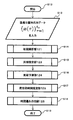
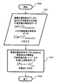
- the prediction accuracy estimation unit 16 of the present example estimates the model design information using information regarding the calculation process of the value after the predetermined time of the input time series signal output from the model creation unit 11. Can do. Moreover, the prediction accuracy estimation part 16 of this example can estimate the prediction accuracy information at the time of predicting the value after the predetermined time of an input time series signal using the said prediction model. (1.9) An example of the flow of this control Here, an example of the flow of the control will be described with reference to the flowcharts illustrated in FIGS. First, as illustrated in FIG. 19, when the control is started (step S1), the control unit 1 determines initial parameters used for prediction after a predetermined time of the input time-series signal (step S2).
- L, T E , and M t are included as various arbitrary constants.
- T E represents the predicted end time.
- the control unit 1 shifts the processing to the cycle variation analysis unit 12 (step S4).
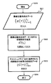
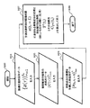
- step S4 when the process is shifted to the cycle fluctuation analysis unit 12, the cycle fluctuation analysis unit 12 starts the process as illustrated in FIG. 20 (step S12). Then, the cycle fluctuation analysis unit 12 receives, for example, an input time series signal from the control unit 1 as time series data of the tumor position.
- Step S13 the process is sequentially shifted to the correlation analysis unit 121, the period estimation unit 123, the surrounding prediction unit 124, the in-phase time estimation unit 125, and the time delay operation unit 126 (steps S14 to S18). Then, the process in the cycle variation analysis unit 12 is terminated (step S19).
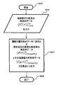
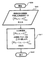
- step S14 when the process is shifted to the correlation analysis unit 121, the correlation analysis unit 121 starts the process as illustrated in FIG. 21 (step S20). Then, the correlation analysis unit 121 receives, for example, an input time series signal from the control unit 1 as time series data of the tumor position.
- step S21 the result of correlation analysis between part of the input time-series signal and the input time-series signal Is calculated and output (step S22). Further, the correlation analysis unit 121 sets time-series data as a result of correlation analysis stored in the cache memory 122. Is output (step S23), and the processing in the correlation analysis unit 121 is terminated (step S24). Next, when the process is shifted to the period estimation unit 123 in step S15, the period estimation unit 123 starts the process as illustrated in FIG. 22 (step S25). Then, the period estimation unit 123 receives, for example, time series data as a result of the correlation analysis from the correlation analysis unit 121.
- step S26 the time series data of the estimated value of the period of the seasonal component included in the input time series signal And time series data of the confidence value Are calculated and output (step S27), and the processing in the period estimation unit 123 is terminated (step S28).
- step S29 the cycle prediction unit 124 starts the process as illustrated in FIG. 23 (step S29).
- step S29 the period predicting unit 124 receives time series data of the estimated value of the period of the seasonal component included in the input time series signal from the period estimating unit 123.
- step S30 time series data of the confidence value Is input (step S30), the time-series data in which the period of the seasonal component included in the input time-series signal is predicted until the prediction target time (t c + L) Is calculated and output (step S31), and the process in the cycle prediction unit 124 is terminated (step S32).
- step S33 time series data of the confidence value Is input
- step S33 time series data of the tumor position.
- Step S34 and the time-series data of the result of the correlation analysis from the correlation analysis unit 121 Is input (step S35), and the time series data of the period prediction result is further output from the period prediction unit 124.
- step S36 the input time series signal of the prediction target time (for example, the tumor position of the prediction target time, etc.) Time that is in phase with the phase of the seasonal component contained in And its reliability Are calculated and output (step S37), and the processing in the in-phase time estimation unit 125 is terminated (step S38).
- the input time series signal of the prediction target time For example, M t pieces of time having the same phase as the phase of the seasonal component included in may be calculated sequentially from the newest.
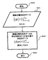
- step S39 when the process is shifted to the time delay operation unit 126 in step S18, the time delay operation unit 126 starts the process as illustrated in FIG. 25 (step S39). Then, the time delay operation unit 126 sends time series data of the cycle prediction result from the cycle prediction unit 124. Is input (step S40), the input time series The time parameter of was delayed by L Is calculated and output (step S41), and the processing in the time delay action unit 126 is terminated (step S42).
- step S5 When the process in the periodic fluctuation analysis unit 12 is completed, the process returns to FIG. 19, and the control unit 1 shifts the process to the variable estimation unit 13 (step S5).
- step S5 When the process is shifted to the variable estimation unit 13 in step S5, the variable estimation unit 13 starts the process as illustrated in FIG.
- step S43 the variable estimation unit 13 receives the input time series signal from the control unit 1 as, for example, time series data of the tumor position. Is input (step S44), the time series data of the amount of change per unit time of the input time series signal Is calculated and output (step S45), and the process in the variable estimator 13 is terminated (step S46).
- step S6 when the process in the variable estimation unit 13 ends, the process returns to FIG. 19 and the control unit 1 shifts the process to the model creation unit 11 (step S6).
- step S6 when the process is shifted to the model creating unit 11, the model creating unit 11 starts the process as illustrated in FIG. 27 (step S47).
- the model preparation part 11 receives the input time series signal from the control part 1 as time series data of the tumor position, for example. (Step S48), and the input time series signal of the prediction target time (for example, the tumor position of the prediction target time, etc.) from the in-phase time estimation unit 125 Time that is in phase with the phase of the seasonal component contained in And its reliability Is input (step S49), and the model design information is further received from the control unit 1.
- step S50 the model design information Design sub-models 111-1 to 111-S based on as well as And a predicted time series signal after a predetermined time of the input time series signal (for example, predicted tumor position, etc.)
- step S51 the process in the model creating unit 11 is terminated
- step S52 the process in the model creation unit 11 is completed, the process returns to FIG. 19 and the control unit 1 shifts the process to the prediction accuracy estimation unit 16 (step S7).
- step S7 when the process proceeds to the prediction accuracy estimation unit 16, the prediction accuracy estimation unit 16 starts the process as illustrated in FIG. 28 (step S53).
- the prediction accuracy estimation unit 16 receives, for example, an input time series signal from the control unit 1 as time series data of the tumor position. (Step S54), and the time series data of the amount of change per unit time of the input time series signal from the variable estimation unit 13 Is input (step S55), and further, the input time series signal of the prediction target time (for example, the tumor position of the prediction target time, etc.) from the in-phase time estimation unit 125 Time that is in phase with the phase of the seasonal component contained in And its reliability (Step S56), and the time series data of the prediction results performed in the past from the model creation unit 11 via the cache memories 14 and 15 And detailed information about the calculation process of the forecast Is input (steps S57 and S58), using the above input information, model design information optimal for prediction And output the predicted tumor location Predicted value of error amount And predicted tumor location Predicted value of change per unit time Are calculated and output (step S59), and the process in the prediction accuracy estimation unit 16 is terminated (step S60).
- the process in the prediction accuracy estimation unit 16 ends, the process returns to FIG. 19, and the control unit 1 determines the predicted value of the tumor position. And predicted tumor location Predictive value of change per unit time (predicted tumor velocity) And predicted tumor location Predicted value of error amount Are output (step S8). Then, the control unit 1, by incrementing the current time t c, to update the time (step S9), and the updated time determines whether less than the predicted end time T E (step S10).
- the control unit 1 when said updated time is determined to be smaller than the predicted end time T E (Yes route in step S10), and repeats the processing from step S3 ⁇ step S9 in FIG. 19.
- the control unit 1 when said updated time is determined to be the predicted end time T E above (No route in step S10), and ends the prediction process (step S11).
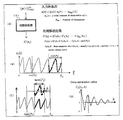
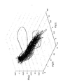
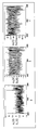
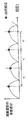
- FIG. 13 is a diagram in which time-series signals of observation positions of a certain affected part 260 are plotted on a three-dimensional space.
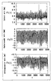
- the time-series signal illustrated in FIG. 14 is a graph of each component in each dimension direction of the time-series signal.
- the scale on the vertical axis is millimeter (mm)
- the scale on the horizontal axis is 0.033 seconds / step.
- the main component in the input time series signal is seasonal dynamics whose behavior is monotonous and stable. Note that it is known from the correlation analysis that the period of this input time-series signal is time-varying.
- the trend component is separated by taking a moving average with the length of the period for the input time series signal, and the difference with the time delay value of the period length for the residual time series signal. It was separated into a seasonal component and other stationary components.
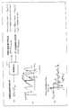
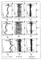
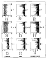
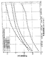
- FIG. 15 shows the result of predicting the value
- FIG. 16A shows the result of predicting the input time series signal as a combination of the outputs.
- the blue line corresponds to the actual measurement value
- the red line corresponds to the prediction result
- Each sub time series corresponds to a component, a seasonal component, and a stationary component.
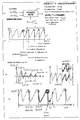
- FIG. 17 also shows the result of predicting the input time-series signal using a conventional general SARIMA model.
- the green line corresponds to the prediction result by the ARMA model.
- the horizontal axis is limited to a section of 2000 steps to 4000 steps for easy viewing.
- the prediction accuracy estimator 16 detects this situation by evaluating the past prediction accuracy results, changes the trend component prediction model to the zero-order hold model, and the prediction result of the seasonal component to the overall prediction result. Model design information is created to increase the proportion occupied by, and reduce the proportion occupied by the prediction result of the steady component. From the result shown in FIG. 16A, the accuracy of the prediction result of the input time series signal obtained by synthesizing all the components is better than that of the conventional general SARIMA model shown in FIG. It can be seen that it is.
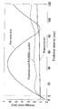
- FIGS. 16B and 16C show the time series information of the error amount of the prediction target time estimated by the prediction accuracy estimation unit 16 of this example and the change amount per unit time of the time series signal, respectively.
- the blue line corresponds to the measured value
- the red line corresponds to the estimated value. From these results, it can be seen that the estimation result by the prediction accuracy estimation unit of this example is highly correlated with the actual measurement value.
- FIG. 18 shows the change in the average prediction error amount when the length L of the prediction period is changed.
- the horizontal axis in FIG. 18 indicates the prediction interval (L), and the vertical axis indicates the average value of prediction errors.
- the result indicated as “Zero-order hold” in the figure represents an error when the latest data of the input time series signal is used as it is as a predicted value.
- the prediction method of this example is effective for medium- and long-term prediction of 5 steps (0.167 seconds) or more.
- control unit 1 of this example can predict the motion of the affected part 260 for a long period (about 1 second) and estimate the prediction accuracy information. For example, prior to the time required for the irradiation field formation control of the MLC 210. MLC 210 can be driven and controlled. As a result, continuous radiation irradiation following the movement of the affected part 260 can be realized. By the way, it can be seen that a specific dynamics change occurs in the vicinity of 3700 steps of the input time series signal.
- the special dynamics change is, for example, the maximum value assumed by the estimated value of the error amount and the change amount per unit time of the time series signal (the output of the corresponding part in FIGS. 16B and 16C is saturated) Can be detected. That is, when specific changes in dynamics continue for a long period of time and it is difficult to accurately predict and follow the movement of the affected area 260, it is difficult to irradiate the radiation by detecting the detected information. Irradiation to normal cells can be avoided.
- the method of this example is effective, in which model design is performed by synthesizing a model and prediction and accuracy thereof are estimated.
- the periodic fluctuation analysis unit 12 of this example is processed by the correlation analysis unit 121.
- the processing when a plurality of values are arbitrarily set can also be performed in parallel. This is because the correlation analysis unit 121 arbitrarily sets a plurality of correlation analysis formulas and data ranges, and sets each setting. When, When, Are calculated simultaneously in parallel.
- variation analysis part 12 calculated in parallel simultaneously, When, When, A variety of model design information using Can be estimated.
- the model creating unit 11 includes not only the filter and model type and parameter values, When, Various submodels 111-1 to 111-S having different combinations with the value of can be created.
- the prediction method of this example before performing the above-described improvement for diversifying the sub-model by setting a plurality of is “prediction method (1) of this example”, and the prediction method of this example after the above-mentioned improvement is “ When “prediction method (2) of this example” is set, the relationship between the prediction period length and the prediction error is as shown in FIG. As shown in FIG.
- the prediction method (1) of this example is more effective than the prediction method based on the seasonally adjusted exponent smoothing method or the SARIMA model, which is an example of a conventional prediction method. It can be seen that the prediction method (2) of this example is more effective than the prediction method (1) of the example.
- control unit 1 may be realized by a computer (including a CPU, an information processing apparatus, and various terminals) executing a predetermined application program (signal processing program).
- the program is a signal processing program for causing a computer to realize the prediction function in the control unit 1 that predicts a value after a predetermined time of an input time series signal
- the signal processing program is an input time series.
- a certain component of the signal is a time-series signal whose period changes with time
- a correlation analysis between a part of the input time-series signal and the input time-series signal is performed, and using the result of the correlation analysis, Estimating the period variation of the input time-series signal and the reliability of the period variation, predicting the period of the input time-series signal up to a predetermined time using the period variation and the reliability of the period variation, and the correlation
- the same-phase time information that is the time of the input time-series signal that is in phase with the phase after the predetermined time of the input time-series signal and the isotope
- a periodic fluctuation analysis function for calculating reliability of time information; the input time-series signal; time-series information
- model design information for predicting the value after the predetermined time of the input time series signal, and the input time series signal of the model design information A prediction accuracy estimation function for estimating a prediction accuracy of a value after the predetermined time; the input time-series signal; and the reliability of the in-phase time information and the in-phase time information calculated by the periodic variation analysis function;
- model design information estimated by the prediction accuracy estimation function to create a prediction model for predicting a value after the predetermined time of the input time-series signal, and using the prediction model A modeling function for the predetermined time after the value predicted by the output of the input time-series signal, the realizing the computer, which is an example of a signal processing program.
- the above-mentioned program is, for example, a flexible disk, CD (CD-ROM, CD-R, CD-RW, etc.), DVD (DVD-ROM, DVD-RAM, DVD-R, DVD-RW, DVD + R, DVD + RW, etc.). It can be provided in a form recorded on a computer-readable recording medium.
- the computer can read the signal processing program from the recording medium, transfer it to the internal storage device or the external storage device, store it, and use it.
- the program may be recorded in a storage device (recording medium) such as a magnetic disk, an optical disk, or a magneto-optical disk and provided from the storage device to a computer via a communication line.
- the computer is a concept including hardware and an OS (operating system), and means hardware operating under the control of the OS. Further, when the OS is unnecessary and the hardware is operated by the application program alone, the hardware itself corresponds to the computer.
- the hardware includes at least a microprocessor such as a CPU and means for reading a computer program recorded on a recording medium.
- the application program as the signal processing program includes a program code for causing the computer as described above to realize the function as the control unit 1. Also, some of the functions may be realized by the OS instead of the application program.
- the recording medium according to the present embodiment includes an IC card, a ROM cartridge, a magnetic tape, a punch card, and an internal storage device of a computer ( It is also possible to use various computer-readable media such as a memory such as a RAM or a ROM, an external storage device, or a printed matter on which a code such as a barcode is printed.
- each structure and each process of the radiotherapy apparatus and the control part 1 mentioned above may be selected as needed, and may be combined suitably.
- the prediction accuracy estimation unit 16 estimates model design information using information regarding a calculation process of a value after a predetermined time of the input time-series signal output from the model creation unit 11. Although described, this estimation process can be omitted.
- the input time series signal is separated into the trend component, the seasonal component, and the steady component, and the prediction model is applied to each of them to predict the input time series signal. Any one of the above components may be selectively separated and used for the prediction process.
- the same effect as described above can be obtained even when only a seasonal component having a higher periodicity than other signal components included in the input time series signal is separated and a predetermined prediction model is applied.
- the signal processing method of this example can also be applied to a system that predicts, for example, the height of a wave or a positional variation caused by a heart beat. For example, it is possible to realize a system or the like that warns to what extent (such as arrhythmia) is deviated from the normal state by predicting the position fluctuation caused by the heart beat by the above signal processing method.
- the present invention compared with the conventional case where the prediction is performed by simply applying the autoregressive model to the input time series signal obtained by inputting the observation signal of the affected area as an input,
- the input time series signal of the position can be predicted accurately and in the medium to long term. Therefore, it is possible to realize radiation irradiation following the movement of the affected area, and it is considered extremely useful in the field of radiation irradiation technology.
Landscapes
- Engineering & Computer Science (AREA)
- Health & Medical Sciences (AREA)
- Physics & Mathematics (AREA)
- Biomedical Technology (AREA)
- Public Health (AREA)
- Nuclear Medicine, Radiotherapy & Molecular Imaging (AREA)
- General Health & Medical Sciences (AREA)
- Radiology & Medical Imaging (AREA)
- General Engineering & Computer Science (AREA)
- Pathology (AREA)
- Life Sciences & Earth Sciences (AREA)
- Animal Behavior & Ethology (AREA)
- Veterinary Medicine (AREA)
- Spectroscopy & Molecular Physics (AREA)
- High Energy & Nuclear Physics (AREA)
- General Physics & Mathematics (AREA)
- Mathematical Optimization (AREA)
- Mathematical Physics (AREA)
- Computational Mathematics (AREA)
- Mathematical Analysis (AREA)
- Pure & Applied Mathematics (AREA)
- Theoretical Computer Science (AREA)
- Data Mining & Analysis (AREA)
- Medical Informatics (AREA)
- Epidemiology (AREA)
- Primary Health Care (AREA)
- Urology & Nephrology (AREA)
- Surgery (AREA)
- Computing Systems (AREA)
- Databases & Information Systems (AREA)
- Software Systems (AREA)
- Algebra (AREA)
- Radiation-Therapy Devices (AREA)
Abstract
Priority Applications (4)
| Application Number | Priority Date | Filing Date | Title |
|---|---|---|---|
| EP09827644.7A EP2359903A4 (fr) | 2008-11-21 | 2009-11-19 | Dispositif de traitement de signal, procédé de traitement de signal, programme de traitement de signal, support d'enregistrement lisible par ordinateur sur lequel est enregistré un programme de traitement de signal, et dispositif de radiothérapie |
| CA2744005A CA2744005C (fr) | 2008-11-21 | 2009-11-19 | Dispositif de traitement de signal, procede de traitement de signal, programme de traitement de signal, support d'enregistrement lisible par ordinateur sur lequel est enregistre un programme de traitement de signal, et dispositif de radiotherapie |
| JP2010539269A JP5604306B2 (ja) | 2008-11-21 | 2009-11-19 | 信号処理装置、信号処理方法、信号処理プログラム及び信号処理プログラムを記録したコンピュータ読み取り可能な記録媒体並びに放射線治療装置 |
| US13/112,361 US8751200B2 (en) | 2008-11-21 | 2011-05-20 | Signal processing for predicting an input time series signal and application thereof to predict position of an affected area during radiotherapy |
Applications Claiming Priority (2)
| Application Number | Priority Date | Filing Date | Title |
|---|---|---|---|
| JP2008-298634 | 2008-11-21 | ||
| JP2008298634 | 2008-11-21 |
Related Child Applications (1)
| Application Number | Title | Priority Date | Filing Date |
|---|---|---|---|
| US13/112,361 Continuation US8751200B2 (en) | 2008-11-21 | 2011-05-20 | Signal processing for predicting an input time series signal and application thereof to predict position of an affected area during radiotherapy |
Publications (1)
| Publication Number | Publication Date |
|---|---|
| WO2010058863A1 true WO2010058863A1 (fr) | 2010-05-27 |
Family
ID=42198302
Family Applications (1)
| Application Number | Title | Priority Date | Filing Date |
|---|---|---|---|
| PCT/JP2009/069992 WO2010058863A1 (fr) | 2008-11-21 | 2009-11-19 | Dispositif de traitement de signal, procédé de traitement de signal, programme de traitement de signal, support d'enregistrement lisible par ordinateur sur lequel est enregistré un programme de traitement de signal, et dispositif de radiothérapie |
Country Status (5)
| Country | Link |
|---|---|
| US (1) | US8751200B2 (fr) |
| EP (1) | EP2359903A4 (fr) |
| JP (1) | JP5604306B2 (fr) |
| CA (1) | CA2744005C (fr) |
| WO (1) | WO2010058863A1 (fr) |
Cited By (4)
| Publication number | Priority date | Publication date | Assignee | Title |
|---|---|---|---|---|
| US10016625B2 (en) | 2014-12-19 | 2018-07-10 | Kabushiki Kaisha Toshiba | Medical image processing apparatus, treatment system, medical image processing method, and medical image processing program |
| JP2019503260A (ja) * | 2016-01-29 | 2019-02-07 | エレクタ リミテッド | 周期運動モデルに基づく運動予測を用いた治療制御 |
| US10335612B2 (en) | 2014-09-19 | 2019-07-02 | Kabushiki Kaisha Toshiba | Particle beam treatment system, particle beam treatment method, and computer program product |
| CN111604908A (zh) * | 2020-06-04 | 2020-09-01 | 云南电网有限责任公司电力科学研究院 | 一种架空线路检修机器人机械臂的力位混合控制方法 |
Families Citing this family (9)
| Publication number | Priority date | Publication date | Assignee | Title |
|---|---|---|---|---|
| DK2308561T3 (da) * | 2009-09-28 | 2011-10-03 | Ion Beam Applic | Kompakt gantry til partikelterapi |
| KR102106535B1 (ko) * | 2013-02-06 | 2020-05-06 | 삼성전자주식회사 | 일 호흡 주기에 따른 장기의 형상 및 위치의 변화를 나타내는 모델을 생성하는 방법, 장치 및 시스템. |
| WO2015102681A2 (fr) * | 2013-09-11 | 2015-07-09 | The Board Of Trustees Of The Leland Stanford Junior University | Procédés et systèmes de génération et de distribution de puissance rf pour faciliter des radiothérapies rapides |
| WO2015038832A1 (fr) | 2013-09-11 | 2015-03-19 | The Board Of Trustees Of The Leland Stanford Junior University | Réseaux de structures d'accélération et imagerie rapide pour faciliter des radiothérapies rapides |
| US10702708B2 (en) * | 2015-09-25 | 2020-07-07 | Varian Medical Systems, Inc. | Accounting for imaging-based radiation doses |
| US10603518B2 (en) * | 2017-03-14 | 2020-03-31 | Varian Medical Systems, Inc. | Rotatable cantilever gantry in radiotherapy system |
| CN111985673A (zh) * | 2019-05-22 | 2020-11-24 | 三菱重工业株式会社 | 预测装置、预测系统、预测方法以及记录介质 |
| CN110275133B (zh) * | 2019-06-27 | 2021-06-29 | 清华大学 | 一种基于虚拟到达时差的非共视脉冲信号无源定位方法 |
| JP7483437B2 (ja) * | 2020-03-23 | 2024-05-15 | キヤノンメディカルシステムズ株式会社 | 放射線照射制御装置、放射線治療システム及び放射線照射制御方法 |
Citations (2)
| Publication number | Priority date | Publication date | Assignee | Title |
|---|---|---|---|---|
| JP2006051199A (ja) | 2004-08-12 | 2006-02-23 | Mitsubishi Heavy Ind Ltd | 放射線治療装置、放射線治療装置の患部追尾方法及びイメージング画像の画質向上方法 |
| JP2008514352A (ja) * | 2004-09-30 | 2008-05-08 | アキュレイ インコーポレイテッド | 運動中の標的の動的追跡 |
Family Cites Families (17)
| Publication number | Priority date | Publication date | Assignee | Title |
|---|---|---|---|---|
| US5626140A (en) * | 1995-11-01 | 1997-05-06 | Spacelabs Medical, Inc. | System and method of multi-sensor fusion of physiological measurements |
| US5884037A (en) * | 1996-10-21 | 1999-03-16 | International Business Machines Corporation | System for allocation of network resources using an autoregressive integrated moving average method |
| US6335961B1 (en) * | 1998-10-06 | 2002-01-01 | Siemens Medical Systems, Inc. | Integrated high definition intensity multileaf collimator system which provides improved conformal radiation therapy while minimizing leakage |
| US6621889B1 (en) * | 1998-10-23 | 2003-09-16 | Varian Medical Systems, Inc. | Method and system for predictive physiological gating of radiation therapy |
| US7050957B2 (en) * | 2001-02-26 | 2006-05-23 | Agere Systems Inc. | Projection electron beam lithography apparatus and method employing an estimator |
| DE60238842D1 (de) * | 2001-08-24 | 2011-02-17 | Mitsubishi Heavy Ind Ltd | Radiologisches behandlungsgerät |
| GB0130010D0 (en) * | 2001-12-14 | 2002-02-06 | Isis Innovation | Combining measurements from breathing rate sensors |
| WO2005081842A2 (fr) * | 2004-02-20 | 2005-09-09 | University Of Florida Research Foundation, Inc. | Système d’administration d’une thérapie de radiation conformée pendant l'imagerie simultanée de tissu mou |
| DE602006021803D1 (de) * | 2005-07-22 | 2011-06-16 | Tomotherapy Inc | System zur Verabreichung einer Strahlentherapie auf ein sich bewegendes Zielgebiet |
| US7880154B2 (en) * | 2005-07-25 | 2011-02-01 | Karl Otto | Methods and apparatus for the planning and delivery of radiation treatments |
| US7906770B2 (en) * | 2005-07-25 | 2011-03-15 | Karl Otto | Methods and apparatus for the planning and delivery of radiation treatments |
| US7902530B1 (en) * | 2006-04-06 | 2011-03-08 | Velayudhan Sahadevan | Multiple medical accelerators and a kV-CT incorporated radiation therapy device and semi-automated custom reshapeable blocks for all field synchronous image guided 3-D-conformal-intensity modulated radiation therapy |
| JP2008003920A (ja) * | 2006-06-23 | 2008-01-10 | Toshiba Corp | 時系列データの予測・診断装置およびそのプログラム |
| US7570738B2 (en) * | 2006-08-04 | 2009-08-04 | Siemens Medical Solutions Usa, Inc. | Four-dimensional (4D) image verification in respiratory gated radiation therapy |
| US7469035B2 (en) * | 2006-12-11 | 2008-12-23 | The Board Of Trustees Of The Leland Stanford Junior University | Method to track three-dimensional target motion with a dynamical multi-leaf collimator |
| US8027430B2 (en) * | 2007-07-30 | 2011-09-27 | Varian Medical Systems International Ag | Systems and methods for adapting a movement model based on an image |
| JP4444338B2 (ja) * | 2008-01-30 | 2010-03-31 | 三菱重工業株式会社 | 放射線治療装置制御装置および放射線照射方法 |
-
2009
- 2009-11-19 WO PCT/JP2009/069992 patent/WO2010058863A1/fr active Application Filing
- 2009-11-19 EP EP09827644.7A patent/EP2359903A4/fr not_active Withdrawn
- 2009-11-19 CA CA2744005A patent/CA2744005C/fr not_active Expired - Fee Related
- 2009-11-19 JP JP2010539269A patent/JP5604306B2/ja not_active Expired - Fee Related
-
2011
- 2011-05-20 US US13/112,361 patent/US8751200B2/en active Active
Patent Citations (2)
| Publication number | Priority date | Publication date | Assignee | Title |
|---|---|---|---|---|
| JP2006051199A (ja) | 2004-08-12 | 2006-02-23 | Mitsubishi Heavy Ind Ltd | 放射線治療装置、放射線治療装置の患部追尾方法及びイメージング画像の画質向上方法 |
| JP2008514352A (ja) * | 2004-09-30 | 2008-05-08 | アキュレイ インコーポレイテッド | 運動中の標的の動的追跡 |
Non-Patent Citations (1)
| Title |
|---|
| See also references of EP2359903A4 |
Cited By (7)
| Publication number | Priority date | Publication date | Assignee | Title |
|---|---|---|---|---|
| US10335612B2 (en) | 2014-09-19 | 2019-07-02 | Kabushiki Kaisha Toshiba | Particle beam treatment system, particle beam treatment method, and computer program product |
| US11413476B2 (en) | 2014-09-19 | 2022-08-16 | Kabushiki Kaisha Toshiba | Particle beam treatment system, particle beam treatment method, and computer program product |
| US10016625B2 (en) | 2014-12-19 | 2018-07-10 | Kabushiki Kaisha Toshiba | Medical image processing apparatus, treatment system, medical image processing method, and medical image processing program |
| US10258813B2 (en) | 2014-12-19 | 2019-04-16 | Kabushiki Kaisha Toshiba | Medical image processing apparatus, treatment system, medical image processing method, and medical image processing program |
| JP2019503260A (ja) * | 2016-01-29 | 2019-02-07 | エレクタ リミテッド | 周期運動モデルに基づく運動予測を用いた治療制御 |
| CN111604908A (zh) * | 2020-06-04 | 2020-09-01 | 云南电网有限责任公司电力科学研究院 | 一种架空线路检修机器人机械臂的力位混合控制方法 |
| CN111604908B (zh) * | 2020-06-04 | 2022-09-02 | 云南电网有限责任公司电力科学研究院 | 一种架空线路检修机器人机械臂的力位混合控制方法 |
Also Published As
| Publication number | Publication date |
|---|---|
| US20110266464A1 (en) | 2011-11-03 |
| CA2744005C (fr) | 2017-04-25 |
| JPWO2010058863A1 (ja) | 2012-04-19 |
| US8751200B2 (en) | 2014-06-10 |
| JP5604306B2 (ja) | 2014-10-08 |
| EP2359903A4 (fr) | 2015-04-22 |
| EP2359903A1 (fr) | 2011-08-24 |
| CA2744005A1 (fr) | 2010-05-27 |
Similar Documents
| Publication | Publication Date | Title |
|---|---|---|
| JP5604306B2 (ja) | 信号処理装置、信号処理方法、信号処理プログラム及び信号処理プログラムを記録したコンピュータ読み取り可能な記録媒体並びに放射線治療装置 | |
| CN100514230C (zh) | 具有可变动态特性的过程的自适应控制的一种系统和方法 | |
| US20200258227A1 (en) | Method and System for Image Registration Using an Intelligent Artificial Agent | |
| EP3407972B1 (fr) | Contrôle thérapeutique au moyen de la prédiction de mouvement | |
| US9028422B2 (en) | Patient monitor | |
| US20150051480A1 (en) | Method and system for tracing trajectory of lesion in a moving organ using ultrasound | |
| JP4926944B2 (ja) | 高分解能撮像 | |
| CN110997063A (zh) | 用于实时图像引导放射治疗的方法 | |
| EP3436148B1 (fr) | Planification d'une radiothérapie adaptative | |
| WO2012008500A1 (fr) | Dispositif de traitement de signal, programme de traitement de signal et support d'enregistrement lisible par ordinateur ayant un programme de traitement de signal enregistré sur celui-ci | |
| CN109069861A (zh) | 质子疗法中的剂量分布估计 | |
| JP2009045229A (ja) | スキャニング照射方法およびスキャニング照射装置 | |
| CN108771794A (zh) | 用于生成辐射处理计划中的剂量计算的系统和方法 | |
| CN104984481A (zh) | 对呼吸产生的肿瘤运动进行在线补偿的方法及系统 | |
| Krilavicius et al. | Predicting respiratory motion for real-time tumour tracking in radiotherapy | |
| CN110108302B (zh) | 一种提高原子团对抛精度的方法 | |
| US20220314027A1 (en) | Treatment planning system, treatment planning generation method, and recording medium | |
| CN111773558B (zh) | 一种使用光栅伺服剂量率的方法、装置及放射治疗设备 | |
| Ichiji et al. | Respiratory motion prediction for tumor following radiotherapy by using time-variant seasonal autoregressive techniques | |
| US8614410B2 (en) | Diffraction fields for guiding an object to a target | |
| US20240115882A1 (en) | Monitoring of system latency errors in radiotherapy for cancer treatment | |
| Sahih et al. | Respiratory motion prediction for adaptive radiotherapy | |
| Murphy | Artificial neural networks to emulate and compensate breathing motion during radiation therapy | |
| US9649508B2 (en) | Methods, systems and computer readable storage media storing instructions for determining patient specific treatment planning margins | |
| CN108984974A (zh) | 卷积自编码器的设计方法和系统 |
Legal Events
| Date | Code | Title | Description |
|---|---|---|---|
| 121 | Ep: the epo has been informed by wipo that ep was designated in this application |
Ref document number: 09827644 Country of ref document: EP Kind code of ref document: A1 |
|
| ENP | Entry into the national phase |
Ref document number: 2010539269 Country of ref document: JP Kind code of ref document: A |
|
| WWE | Wipo information: entry into national phase |
Ref document number: 2744005 Country of ref document: CA |
|
| NENP | Non-entry into the national phase |
Ref country code: DE |
|
| WWE | Wipo information: entry into national phase |
Ref document number: 2009827644 Country of ref document: EP |